Main data of 20 Ton High Version Air Service Jack
LIING
MIN. MAX.
N.W. G.W.
PACKAGE
AIR
-CAPACITY
HEIGHT HEIGHT (KG) (KG) SIZE PRESSURE
22n
8.3
i
n 21
i
n 101
lbs
110
lbs
26 x 14 x 11
i
n 0.7-1.0MPA
OWNER/OPERATOR RESPONSIBILITY
It is the owner/operator responsibility to properly use and maintain this equipment and the legibility of all warnings and
instruction labels. Carefully read and understand the instructions and warnings in this manual before operating this
equipment. Keep this manual in a safe location for future reference.
WARNING
&
FAILURE TO READ THESE WARNINGS MAY RESULT IN PROPERT Y DAMAGE AND OR PERSONAL INJURY.
-
Use as lifting device only.
- Use only o
n hard, level surface.
- Do not modify jack.
- Support l
oad by appropriate means after liing
- Do not exceed rated capacity.
- Center load on the jack.
- Only use attachments and/or adapters supplied with or sold specifically for the jack.
- Only lift areas of the vehicle designated by the vehicle manufacturer.
INSPECTION
Prior to each use, visually inspect for leaking hydraulic oil, damaged, loose or missing parts. If jack is wo or damaged
remove from service and contact your nearest service center for repair.
OPERATION
1. Tightl
y close the release valve knob (located on top of the "T" handle) by turning it clockwise.
2. Center the load on the jack saddle. Connect the air supply, and squeeze the air valve lever to raise the load. Release the
air valve lever to stop movement.
3. Transfer the load to support stands.
4. To lower the jack, open the release valve knob gy SLOWLY turning it counterclockwise.
NOTE: To adjust the handle, pull up and then release the lever to lock it in one of the positions.
Bleeding The Jack
Air bubbles can become trapped inside the bydraulic system, reducing the efficiency of the jack. Purge air from the
system as needed by following these steps:
1. With the jack sitting on its base and the ram retracted, bleed air by opening the release valve.
2. Pump for 10 seconds.
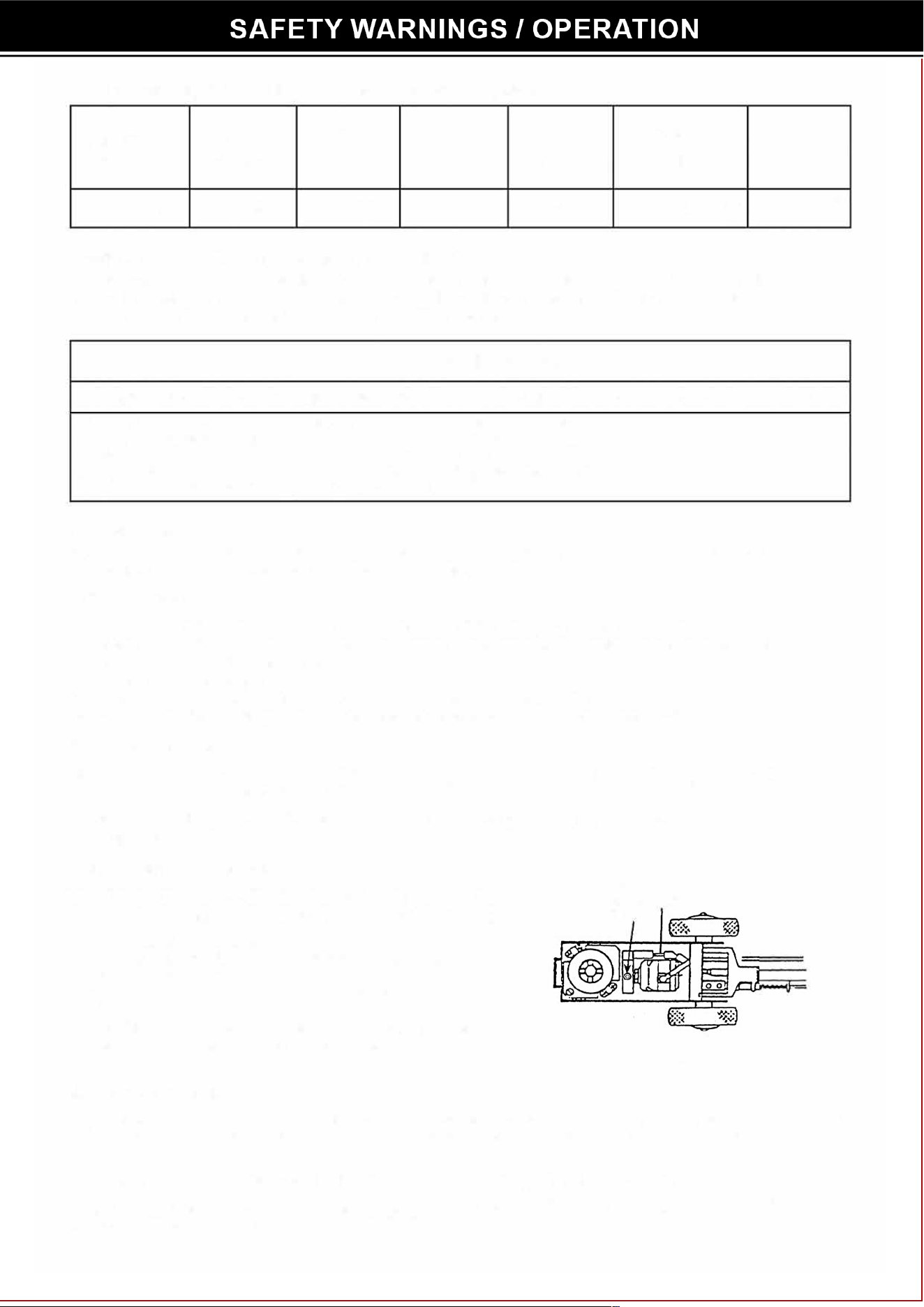
Pump Prime Instructions
The air/hydraulic pump may lose its prime during shipment or after
long periods without use. To prime the pump, llow these steps:
1. Remove the upper cover.
2. Loosen the hex socket bolt one-half turn. See Figure 1.
3. Close the release valve.
4. Operate the air pump while repeatedly tightening and loosening
the bolt.
5. When the piston begins to rise, tighten the bolt. Veri that the
piston can rise to the maximum height position.
MAINTENANCE
Hex
Release
Socket
Valve
Bolt
Figure 1
Check oil level. With the jack in an upright position and the ram completely retracted, open the release valve (turn coun
ter-clockwise) and remove the filler plug. The oil level should be just up to the hole. Fill if necessary with cleanhydraulic
jack oil.
Lubricate internal components. With the release valve open, manually pump the handle six times.
Keep the jack clean. Occasionally lubricate the handle socket pivot point, extension screw, release screw thread, and
air valve to prevent corrosion.
Problem
Erratic Action
Ram does not advance
Ram only extends partially
Ram advances slowly
Ram advances but doesn't
hold pressure
Jack leaks oil
Ram will not retract, or
retracts slowly
Cause
1. Air in system
2. Viscosity of oil too high
3. Ram sticking or binding
4. Internal leakage in ram
1 . Release valve is open
2. Low/no oil in reservoir
3. Air locked system
4. Load is above capacity of system
5.
Pump lost its prime
1. Low oil level in reservoir
2. Piston rod is binding
1. Low air pressure
2. Pump not working correctly
3. Leakinq seals
1 . Release valve is open
2. Ram seals are leaking
3. Pump check valve not working
4. Overload valve leaking or
not adjusted
1. Worn or damaged seals
1 . Release valve is closed
2. Reservoir too full
3. Ram damaged internally
Solution
1. With jack sitting on its base and m
retracted, bleed air by opening release
valve. Pump for 10 seconds.
2. Change to a lower viscosity oil.
3. Look r di, gummy deposits, leaks,
misalignment, wo pas, or defective
packing.
4. Replace wo packings. Look for
excessive contamination or wea
1. Close release valve located on top of
"T" handle.
2. Fi with o & bleed system.
3. With jack sitting on its base and ram
retracted, bleed air by opening release
valve, running pump for 1 O seconds.
4. Use coect equipment.
5.
Follow "Pump Prime Instructions" .
1. Fill reservoir with oil, & bleed system.
2. Look for di, gummy deposits, leaks,
misalignment, wo pas, or defective
packing.
1. Adjust air pressure to 90-145 psi.
2. Rework pump.
3. Replace seals.
1. Close release valve located on top of
"T" handle.
2. Replace seals.
3. Clean I replace check valve.
4. Replace I adjust oveoad valve.
1. Replace seals.
1. Open release valve.
2. Drain oil to coect level.
3. Take jack to authorized seice
center for repair .
,.
,._
,._
,.-
.. -
.,-
..
.,,
' !�::
.. - !.t
-11
-·
_,.
\
-106
0-10◄
6-ic
6-1
-10,
.. -
0
-
'
�
.. -
..
o
I
.
.
7
..
I 15
-2
�
_
-LCI
I
-
·
�
6
•
6 _,,
, "\�o
6 _,
,•,,
l
-,.,
/'
e1
,
I
�-·
�� .
.
�
.
'
"'
..
-
66- / �
/
..
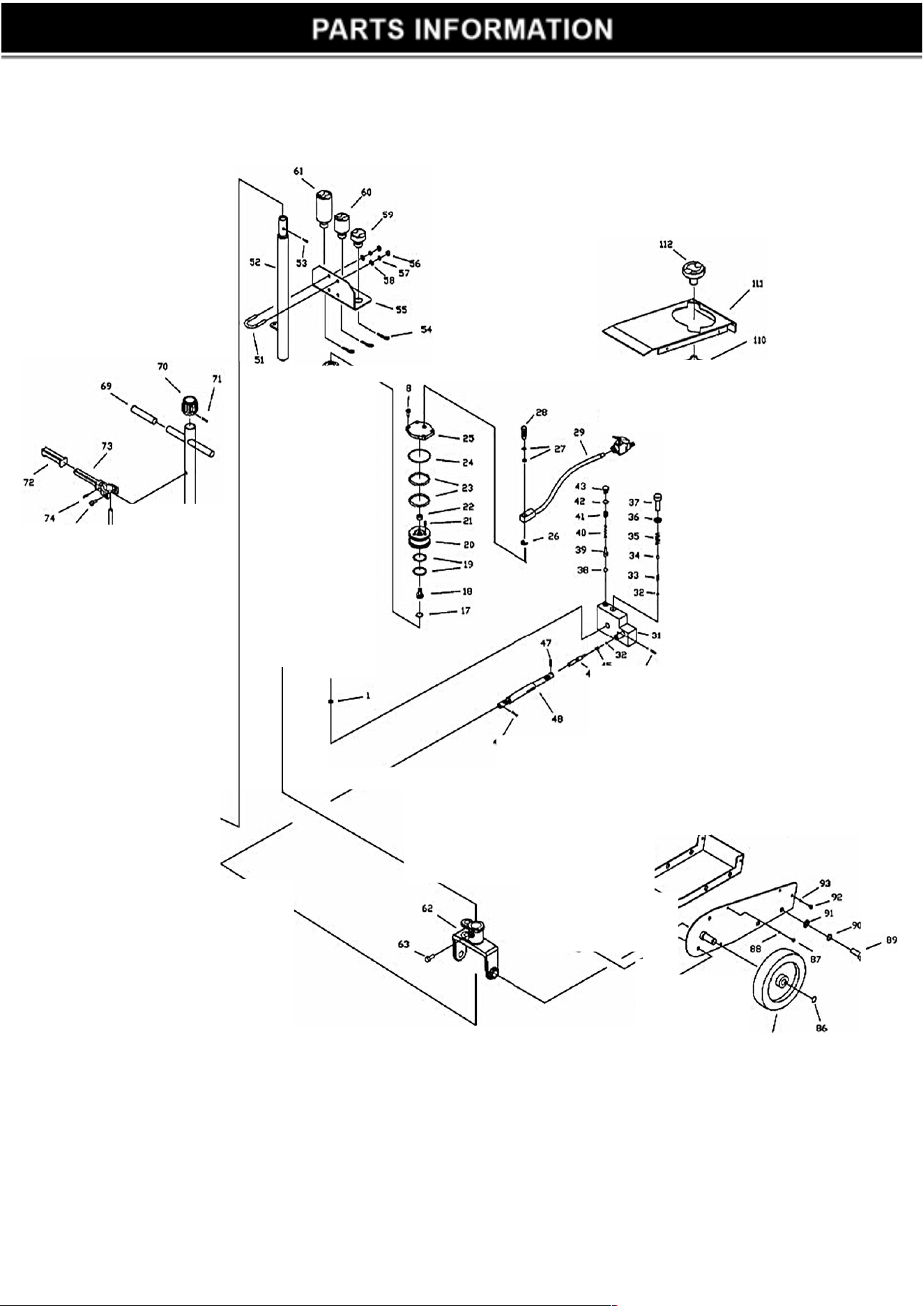
Part No.
Description
Qty.
Part No.
Description
Qty.
1
Coooer Washer
1
57
Lock Washer M8
4
2
Pump Cylinder 1
58 Flat Washer M8
4
3
Y-seal
5.8X12X5.2mm 1
59
Adapter Dia. 48x20mm
1
4
Nylon Gasket 5.8X12X1 .25mm 1 60
Adapter Dia. 48x50mm
1
5
Copper Washer
1
61
Adapter Dia. 48x100mm
1
6
Nut
1 62 Handle Socket 1
7
O-rina
18X2.65mm
1
63
Handle Socket Bolt
1
8
Socket Head Cap Screw
M6X20mm
8
64
Rod Joint
1
9
Base Cover 1
65
Convey Rod B
1
10
Steel Ball
Dia. 3mm
4
66
Flat Washer M10
5
11
Air Mater HousinQ
1
67
Cross Socket Head Screw M5x8
1
12
Nut
1
68
Rear Handle
1
13
Spring
1
69
Handle Sleeve
2
14
Washer
1
70 Knob
1
15 Air Pump Plunaer
1
71
Lock Pin
Dia. 4x40mm
1
16
Air Piston Base
1
72
Sleeve
1
17
O-rinq 20.3X2.65mm 1
73
Lock Lever
1
18
Air Shuttle Valve
1
74
Lock Pin Dia. 3x18mm 1
19
O-rina
43X3.55mm
2
75
Socket Head Cao Screw M5X10mm
2
20
Air Piston 1
76
Control Rod A
1
21
Socket Head Cao Screw M5X10mm
3
77
Spring
1
22
Shuttle Valve Seal
1
78
Control Rod B
1
23
O-rinQ 57X5.3mm 2
79
Frame Left
1
24
O-rina 67X2.4mm
1
80
Bracket
1
25
Top Cover
1
81
Chassis
1
26
Snap Rina Dia. 14mm
1
82 Frame Riaht
1
27
O-ring 11.5X1 .5mm
2
83
Lock Washer M10 4
28
Coupler
1
84
Hex Bolt M10x16mm
4
29
Air Hose Assy. 1
85
Wheel
2
30
Air Valve Assy.
1
86
Snap RinQ
Dia. 15mm 2
31
Valve Block Assy.
1
87
Cross Socket Head Cap Screw M5x12
4
32 Steel Ball
Dia. 6mm
2
88
Flat Washer M5
4
33
Sorina 1
89
Hex Bolt M12x25 4
34
Steel Ball
Dia. 9mm
1
90
Lock Washer M12
4
35
Sorina
1
91
Flat Washer M12
4
36
Copper Washer
1
92
Cross Socket Head Cap Screw M6x12
4
37
Socket Head Cap Screw M12x20mm
1
93
Flat Washer M6 4
38
Steel Ball Dia. 4mm 1
94
Socket Head Cao Screw M8x25
3
39
Safety Valve Ball Seat 1
95
O-rinQ 7.1x2.65mm
3
40
Safety Valve Sorina
1
96
Oil Filler Plug 1
41
Safety Valve Adjusting Screw 1
97
Oil Tank Assy.
1
42
Seal
1
98
Snap Ring Dia. 48mm
1
43
Safety Valve Screw
1
99
O-rinQ Retainer 1
44
Lock Pin
Dia. 4x20mm
3
100
O-ring 53x5.3mm
1
45
Seal 1
101
Seal Washer
1
46
Release Rod
1
102
Piston Ring 1
47 Pin
Dia. 3x18mm
1
103
Ram Assy.
1
48
Universal Joint Assy. 1 104
Bushing
2
49
Rod Joint 1
105
O-rinQ 61.5x5.3mm 1
50 Convey Rod A
1
106
Snap Ring
1
51
U-bolt
2
107
Nut M10 (thin)
2
52
Front Handle
1
108 Sorina 2
53
Lock Pin
Dia. 4x16mm
1
109
Bolt
2
54
Hair Pin
3 110
Sorina hanaer
1
55
Angular Bracket
1
111
Cover
1
56
Nut M8
5 112
Adapter Dia. 68x20mm
1