
Gasoline Power Tiller
Original Instructions

TABLE OF CONTENTS
SAFELY NOTES..........................................................................................................................................................1
INTRODUCTION........................................................................................................................................................4
INSTRUCTION FOR MOTORHOE ASSEMBLY................................................................................................6
STARTING AND STOPPING..................................................................................................................................6
USE AND ADJUSTMENT.........................................................................................................................................7
MAINTENANCE.........................................................................................................................................................7
MAIN TECHNICAL PARAMETERS......................................................................................................................8
BREAKDOWN LIST...................................................................................................................................................9
WARRANTY................................................................................................................................................................10
EMISSION CONTROL SYSTEM WARRANTY STATEMENT........................................................................11
1.
SAFELY NOTES
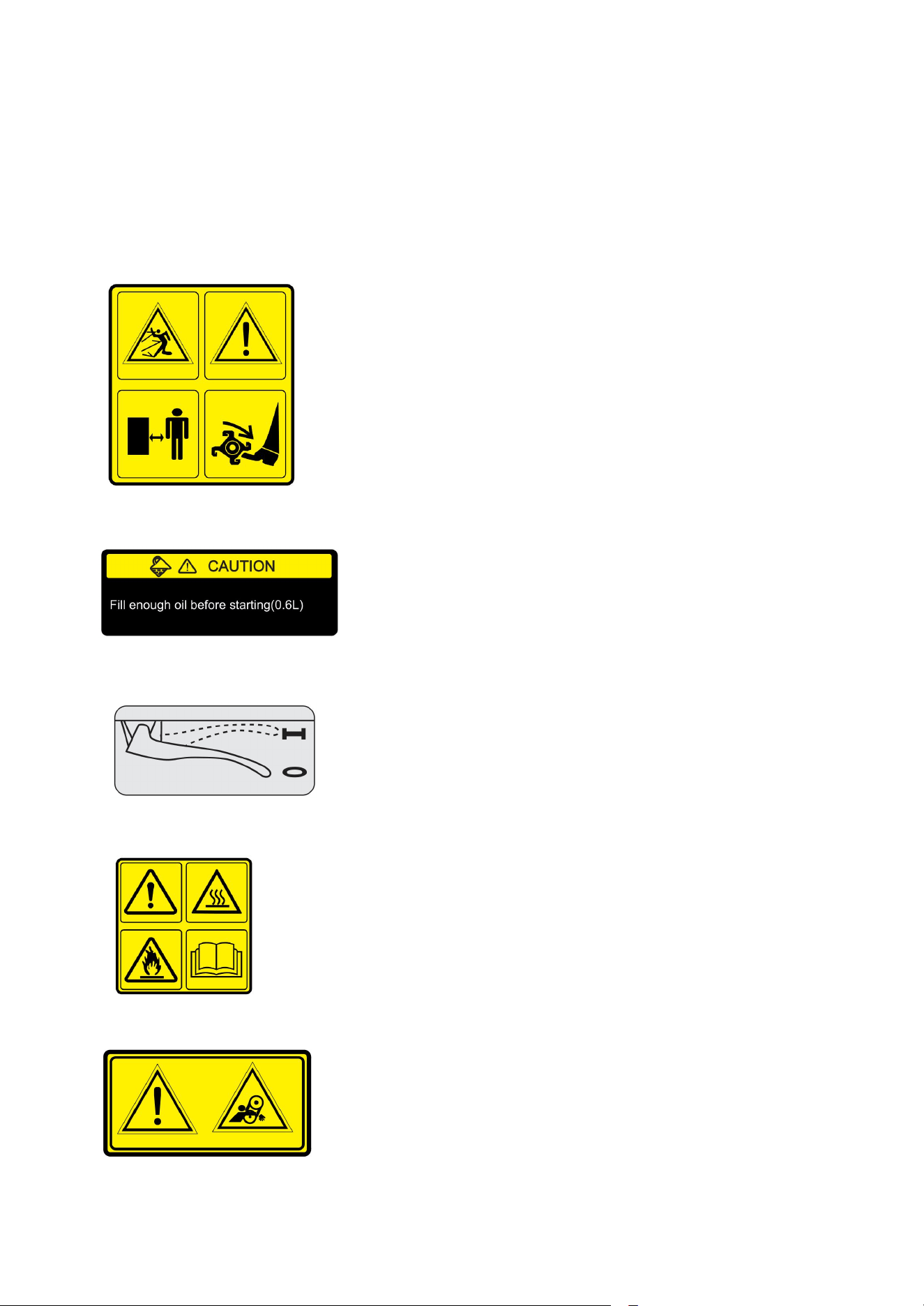
1.1 SAFETY LABELS
The following safety labels appear on the machine. They are there to remind you of the care and attention
required in use. This is what the symbols mean:
1) When the machine is working, do not be too close to the machine to avoid being hurt by the revolving blades.
2) Fill engine oil (0.6L)!
3) “O”: stop position (clutch disengage), “I”: move on position (clutch engage).
4) The fuel tank warning signs.
5) The belt cover: warning signs.
1

1.2SECURITY TERMS
a) The machine shall always be used in accordance with the manufacturer'’ instructions laid down in the
instruction handbook;
b) The engine shall be stopped when carrying out maintenance and cleaning operations, when changing tools and
when being transported by means other than under its own power;
c) The machine should only be operated by suitably trained persons;
d) Read the instructions carefully. Be familiar with the controls and the proper use of the equipment;
e) Never allow children or people unfamiliar with these instructions to use the machine. Local regulations can
restrict the age of the operator;
f) Never work while people, especially children, or pets are nearby;
g) Keep in mind that the operator or user is responsible for accidents or hazards occurring to other people or their
property.
h) While working, always wear substantial footwear and long trouser. Do not operate the equipment when
barefoot or wearing open sandals;
i) Thoroughly inspect the area where the equipment is to be used and remove all objects which can be thrown up
by the machine;
j) WARNING – Petrol is highly flammable:
- store fuel in containers specifically designed for this purpose;
- refuel outdoors only and do not smoke while refuelling;
- add fuel before starting the engine. Never remove the cap of the fuel tank or add petrol while the engine is
running or when the engine is hot;
- if petrol is spilled, do not attempt to start the engine but move the machine away from the area of spillage and
avoid creating any source of ignition until petrol vapours have dissipated;
- replace all fuel tank and container caps securely;
k) Replace faulty silencers;
l) Before using, always visually inspect to see that the tools are not worn or damaged. Replace worn or damaged
elements and bolts in sets to preserve balance.
m) Do not operate the engine in a confined space where dangerous carbon monoxide fumes can collect;
n) Work only in daylight or in good artificial light;
o) Always be sure of your footing on slopes;
p) Walk, never run with the machine;
q) Exercise extreme caution when changing direction on slopes;
r) Do not work on excessively steep slopes;
s) Use extreme caution when reversing or pulling the machine towards you;
t) Do not change the engine governor settings or overspeed the engine;
u) Start the engine carefully according to manufacturer instructions and with feet well away from the tool(s);
v) Do not put hands or feet near or under rotating parts;
w) Never pick up or carry a machine while the engine is running;
x) Stop the engine:
- whenever you leave the machine
- before refuelling;
y) reduce the throttle setting during engine shut down and, if the engine is provided with a shut-off value, turn the
fuel off at the conclusion of working;
z) keep all nuts, bolts and screws tight to ensure the equipment is in safe working condition;
aa) never store the equipment with petrol in the tank inside a building where fumes can reach an open flame or
spark;
ab) allow the engine to cool before storing in any enclosure;
ac) to reduce the fire hazard, keep the engine, silencer, battery compartment and petrol storage area free of
vegetative material and excessive grease;
ad) replace worn or damaged parts for safety;
ae) if the fuel tank has to be drained, this shall be done outdoors.
2

WARNING:
Failure to comply with these instructions may result insidious or even cause fatal injury.
The use of the machine is forbidden to persons younger than 16 years.
The operator is responsible of any possible damage and he should always drive the machine carefully and safety.
Before carrying the machine always empty the fuel tank.
Before leaving the machine be sure that it is fully stopped.
Never use the machine without heavy shoes and long transfers. Always inspect the area where you want to work
taking off stones, branches, cables and any other thing which can be dangerous.
Before start working, make sure that a radius of minimum 5 mm is completely free.
Clean any possible leakage of fuel.
Fill up when the engine is off and not hot, always in an open space far from fires or any heating source and refrain
from smoking during this operation.
Before starting the machine make sure that you can quickly stop the engine and that you are familiar with the
control levers.
Never allow the engine to run in enclosed spaces where the highly toxic carbon monoxide could not evacuate.
Never start or use the machine not completely assembled especially concerning the safety devices and the tiller
protection guards which should always be completely assembled with all its extensions.
Never fix or clean the tiller blades or any other tools when the engine is running.
ATTENTION:
Don’t use the machine on sloping grounds exceeding the 30%.
We are not responsible for accidents due to the wrong use of the machine neglecting the above basic instructions.
3
2. INTRODUCTION
This machine has a high efficiency for revolving farming, working in dry land,
orchard, vegetable garden and
greenhouse, etc.
Dear user, thank you for preferring ,The top performance and the easy use of our machine should give you any
satisfaction.
This machine is the result of a long experience working at the top quality standard and using first quality material.
Carefully using and servicing this machine,you will certainly get satisfactory performances for a long time.
Please read very carefully this booklet before using your cultivator.
The greater attention you give to our technical instructions the more reliable your machine will be. Pay special
attention to the instructions marked out by the following sign.
DANGER!
Failure to comply with these instructions may result insidious or even cause fatal injury.
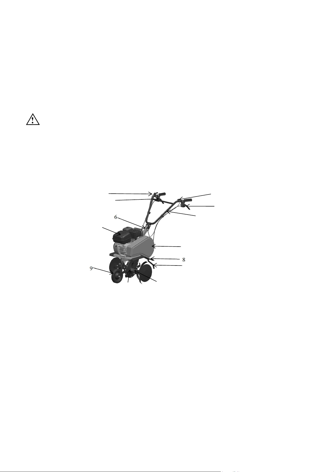
PARTS OF THE GASOLINE POWER TILLER
1.Throttle Lever, 2.Reverse clutch Handle, 3.S
hut down,
4.Clutch Handle, 5.
Handrail,
6.Armrest seat, 7.Engine,
8.Fender, 9.Front wheel, 10.Gearbox Assy, 11.Blade, 12.Belt Cover, 13.Drag tilling knife
1
2
3
4
5
7
10
11
12
13
4
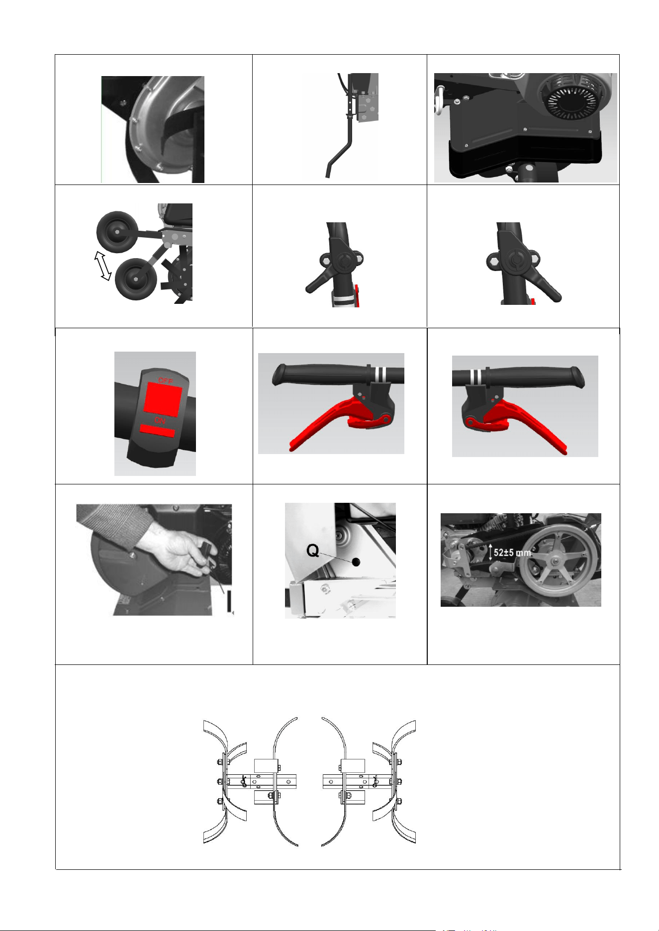
Pict.8 Pict.9Pict.7
Pict.10
530mm
P
ict.12
Pict.13
Pict.11
Pict.
1
Pict.2 Pict. 3
Pict.4 Pict.5(Low) Pict.6(High)
5

The engine fitted on this cultivator have following features:
Exhaust guard
Recoil starter
Oil Bath air filter
ENGINE LUBRICATION WITH: see instruction manual of the engine.
Quantity of engine oil: see instruction manual of the engine.
Fuel: unleaded petrol
Safety device for forward gear stopping the tiller.
The model EDPT01has a front belt transmission for the engine and a greased chain for the tiller.
The handlebar can be:
1. adjustable in 3 vertical positions
2. adjustable in different positions (height )
The tiller can be of 83 cm or 95 cm.
The gear-box is screwed(Pict.1).
The Resistance plough can be adjustable (Pict.2).
All the identification references (code number, engine type, weight, power, work width) are printed on the number
plate on the machine (Pict.3).
4. INSTRUCTION FOR MOTORHOE ASSEMBLY
4.1 Adjust steering handle through locking handle bar.
4.2 You can use 2pcs of B type axis Pin(10*45) ,2pcs R pin,4pcs of washer(diameter 10),and front wheel spring to fix
front wheel supportor.
4.3 You can use bolt(M12*80),Nut M12 to fix front wheel.
And pull front wheel till B type axis pin fixed when you do not use front wheel(see pict4)
5. STARTING AND STOPPING
Starting the engine of the machine always follow these instructions very carefully:
Check the oil in the engine:
THE BRAND NEW MACHINE IS DELIVERED WITHOUT OIL IN THE ENGINE, THEREFORE YOU
SHOULD FILL IT UP TO THE LEVEL ON THE DIP STICK OF THE OIL CUP.
Please check the engine USE AND MAINTENANCE concerning the “operations before staring”.
Start the engine only in open spaces.
1. Pull the choke lever on the engine(where present is).
2. Turn the accelerator lever to the “FAST” position (Pict.6).
Turn the engine switch to the ON position
(Pict.5)
.
3. The clutch lever should be released (Pict.8 and Pict.9).
4.Pull the starting rope by the handle smoothly first than strongly: when you feel some resistance don’t leave the
handle but help the recoiling of the rope with your hand (Pict.10).
6
5. When the engine runs move the choke lever to the initial position and the accelerator lever in the mid-position.
6 . For stopping the engine move the accelerator lever in “LOW” position (Pict.5).
Turn the engine switch to OFF
position
(Pict.7)
.
Every year you should introduce some grease through the hole “Q” (Pict.11) in the main
body.
Keep the machine and the tillers clean and check that all the screws and nuts are well tied, especially the screws
of the tiller (always wear protection gloves working on the tiller).
6. USE AND ADJUSTMENT
6.1 Grasp clutch handle bar (pict8), Tiller stop.
6.2 When machine need reverse, Grasp reverse handle bar(pict9).
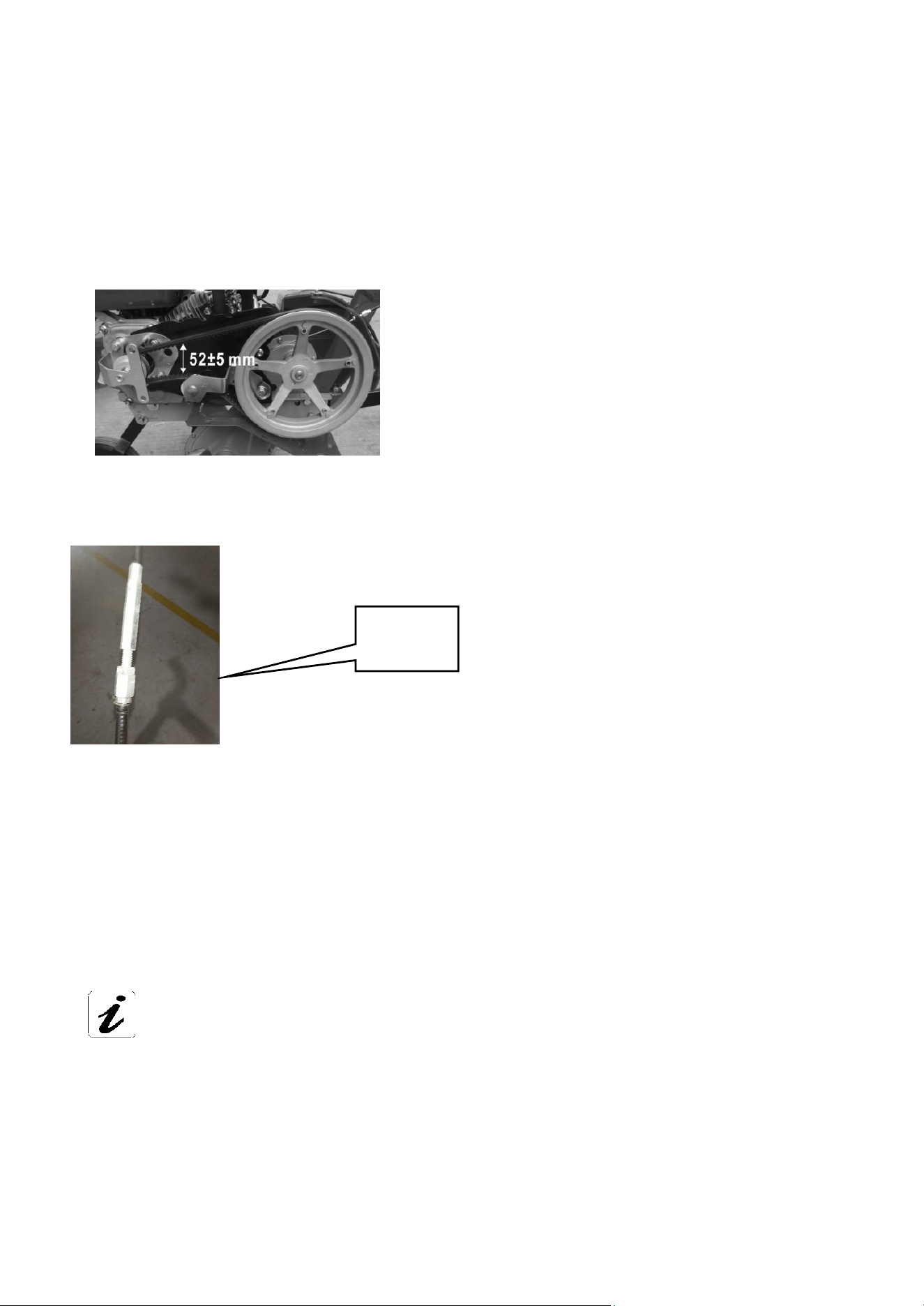
6.3 Model NO. EDPT01,Distance between belt is 52±5 mm.
Please note only take off screw from front supportor , and belt cover, then you can check
the belt distance,(see photo below).
if clutch is not working properly, The best way is adjust clutch cable nut to proper position
as photo below
:
Grasp clutch handle bar, and loosen handle bar, the tension distance is 10mm, if you can
not adjust distance to 10mm by nut, then please try following method:
1,Take off bolt from engine supportor, and adjust position that you need.
7. MAINTENANCE
For the normal maintenance (oil, filter, spark plug) check the booklet for the engine included.
The chain for the final transmission is lubricated with normal grease.
Clutch
cable nut
7

In case of breaking or wearing you can replace the belt after taking off the side protection cover fixed to the
frame near the engine shaft by two screws.
Remove the belt from the pulleys, install the new belt end adjust it following the instructions mentioned in the
chapter USE AND ADJUSTMENT by checking the distance between both sides of the belt, then replace the
cover.
The pin fixing the big pulley has also a safety purpose: in case heavy obstacle it will break avoiding damages
to other parts of the machine.
The replacement of the pin is very easy: you have to insert the new pin in the hole using a hammer.
For any technical repair especially during the guarantee period, it is recommendable to apply to the specialized
workshops of our dealers.
CAUTION:
It is advised not to keep the motor running when the machine is not being used for
its specific purpose.
3. MAIN TECHNICAL PARAMETERS
Model EDPT01
Engine type H170F
Rated engine power 4.0kW
Rated speed 3600r/min
Displacement 212cc
Tilling Width 530mm
Tilling Depth ≥100mm
Blade Type
Tyre Model
2-4
Net weight
8×1.75
54kg
Gross weight 58kg
Work station sound pressure level 82dB(A); K=3dB(A)
Sound pressure level 78dB(A); K=3dB(A)
Sound power level 98dB(A); K=2dB(A)
Vibration level 9.49m/s
2
; K=1.5m/s
2
8

8. BREAKDOWN LIST
Breakdown phenomenon Solution
Insufficient power,Low rotation
open damper, replace muffler
Cause
damper closed, poor ventilation of
muffler
moving parts abrasion check, replace
speed adjustment mechanism failed
to reach the best equilibrium
adjust speed adjustment mechanism
low ignition power replace ignitor or flywheel
excessive clearance of air valve regulate to the required scope
Clear away carbon
excessive fluctuation of speed
adjust speed adjustment mechanism
carbon deposition
speed adjustment mechanism failed
to reach the most optimized
combination
wrong carburetor replace carburetor
adjust clearance
Readjustor install speed adjustment
excessively high speed of rotation
cap
wrong space of spark plug
speed adjusting handle failed to press
adjust cap tightly or Speed adjust cap
lost
abnormal sound
wrong clearance of air valve adjust clearance of air valve
cam gear injured replace camshaft
oil leaking of carburetor
needle valve and oil dirt attached lightly tap carburetor or clean it.
O-ring deformation replace
A. Gasoline engine
(1) Hard to start machine or fail to start
Breakdown phenomenon Cause Solution
no spark at plug
spark plug
carbon deposition of spark plug clear away carbon
excessive or too small clearance
of spark plug
adjust clearance to 0.7~0.8mm
Insulation damage of spark plug replace spark plug
Others
breakdown of ignitor replace ignitor
weak magnetic force of flywheel replace flywheel
Sparking at plug
good compression
suck excessive fuel into cylinder
take off spark plug and dry it and
put it on
poor quality of fuel with water
and dirt
replace fuel
Loosen oil drain
screw at the
bottom of
Carburetor .No oil
shedding.
needle valve block clean or replace carburetor
normal oil supply
but poor
compression
replace
screw tigh
clean, readjust and reassemble
normal ignition
and oil supply
replace and connect
clean
piston ring abrasion, loose spark
plug
Air leak of cylinder head
wrong air valve clearance or
timing
poor contact of high voltage cable
and spark plug
Failure of stop switch , short
circuit
breakdown of oil alert
replace
(2) Abnormal conditions in the movement
9

B. Tiller
Common CausesAbnormalities
Strange noises
Strong vibration
Poor tillage effect
Stuck blade
Leakage of lubricating oil
Loose bolts, nuts and other
components
Damage or wear of the blade
Excessive tillage depth
Shallow tillage
Blunt or worn blade
Measures to be taken
Turn off the tiller until the engine is completely stopped.
Fix it in the repair shop
Tighten all the components, if strange noises remain,
please contact repair shop
Change blade or fix it in repair shop
Adjust the tillage depth
Adjust the tillage depth
Change blade o fix it in repair shop
9. WARRANTY
Our machines and accessories are guaranteed for 1 years excluding electric and rubber parts.
All the defective parts will be replaced free of charge excluding cost of labour and transport freight, which would be
at customer’s charge.
For any problem regarding the engine or any other part not of our production, please refer to the guarantee conditions
stated by the manufacturer and apply to their assistance centres.
For any kind of problem or repair please apply to the dealer where you bought the machine.
NOTE:_
__________________________________________________________
_________________________________________________________________
_________________________________________________________________
_________________________________________________________________
_________________________________________________________________
_________________________________________________________________
_________________________________________________________________
_________________________________________________________________
_________________________________________________________________
_________________________________________________________________
_________________________________________________________________
_________________________________________________________________
_________________________________________________________________
_________________________________________________________________
_________________________________________________________________
_________________________________________________________________
_________________________________________________________________
_________________________________________________________________
10

EMISSION CONTROL SYSTEM WARRANTY STATEMENT
YOUR WARRANTY RIGHTS AND OBLIGATIONS
The U. S. EPA and Shenzhen enfuni Technology Co., Ltd are pleased to explain the
emissions control system warranty on your model year 2025 and later small off-road
engine and equipment (equipment).
New equipment must be designed, built and equipped to meet the stringent anti-smog standards.
Shenzhen enfuni Technology Co., Ltd must warranty the emission control system on your equipment for
the period of time listed below, provided there has been no abuse, neglect or improper maintenance of
your equipment.
Your emission control system may include parts such as the carburetor, air cleaner, ignition system,
exhaust system, and other associated emission-related components.
Where a warrantable condition exists, Shenzhen enfuni Technology Co., Ltd will repair your equipment at
no cost to your including diagnosis, parts and labor.
MANUFACTURER’S WARRANTY COVERAGE
This emissions control system is warranted for two years. If any emission-related part on your equipment
is defective, the part will be repaired or replaced by Shenzhen enfuni Technology Co., Ltd.
OWNER’S WARRANTY RESPONSIBILITIES
As the equipment owner, you are responsible for the performance of the required maintenance listed in
your Owner’s Manual. Shenzhen enfuni Technology Co., Ltd recommends that you retain all your receipts
covering maintenances on your equipment, but Shenzhen enfuni Technology Co., Ltd cannot deny
warranty solely for the lack of receipts or for your failure to ensure the performance to all scheduled
maintenance.
As the equipment owner, you should however be aware that Shenzhen enfuni Technology Co., Ltd may
deny your warranty coverage if your equipment or part has failed due to abuse, neglect, improper
maintenance or unapproved modifications.
You are responsible for presenting your equipment to an Authorized Shenzhen enfuni
Technology Co., Ltd Service Dealer as soon as a problem exists. The warranted repairs
should be completed in a reasonable amount of time, not to exceed 30 days.
If you have any questions regarding your warranty rights and responsibilities, you should contact:
Company: Windrider Tech Co., Ltd.
Contact Person:Austin
Tel.: 4696597752
Mail: [email protected]
Add.: 2707 Realty Road STE 100 Carrollton Texas 75006
11

DEFECTS WARRANTY REQUIREMENTS
Shenzhen enfuni Technology Co., Ltd warrants to the ultimate purchaser and each subsequent purchaser
that the equipment is designed, built and equipped so as to conform with all applicable regulations; and
free from defects in materials and workmanship that cause the failure of a warranted part, and is identical
in all material respects to that part as described in the application for certification.
The warranty period begins on the date the equipment is delivered to an ultimate purchaser or first placed
into service. Subject to certain conditions and exclusions as stated below, the warranty on emission-related
parts is as follows:
1.
Any warranted part that is not scheduled for replacement as required maintenance in the written
instructions supplied is warranted for the warranty period stated above. If the part fails during the period of
warranty coverage, the part will be repaired or replaced by Shenzhen enfuni Technology Co., Ltd
according to subsection (4) below. Any such part repaired or replaced under warranty will be warranted for
the remainder of the period.
2.
Any warranted part that is scheduled only for regular inspection in the written instructions supplied is
warranted for the warranty period stated above. Any such part repaired or replaced under warranty will be
warranted for the remaining warranty period.
3.
Any warranted part that is scheduled for replacement as required maintenance in the written instructions
supplied is warranted for the period of time before the first scheduled replacement date for that part. If the
part fails before the first scheduled replacement, the part will be repaired or replaced by Shenzhen enfuni
Technology Co., Ltd according to subsection (4) below. Any such part repaired or replaced under warranty
will be warranted for the remainder of the period prior to the first scheduled replacement point for the part.
4.
Repair or replacement of any warranted part under the warranty provisions herein must be performed at a
warranty station at no charge to the owner.
5.
Notwithstanding the provisions herein, warranty services or repairs will be provided at all of our distribution
centers that are franchised to service the subject engines or equipment.
6.
The equipment owner will not be charged for diagnostic labor that is directly associated with diagnosis of a
defective, emission-related warranted part, provided that such diagnostic work is performed at a warranty
station.
7.
Shenzhen enfuni Technology Co., Ltd is liable for damages to other engine or equipment components
proximately caused by a failure under warranty of any warranted part.
8.
Throughout the equipment warranty period stated above, Shenzhen enfuni Technology Co., Ltd will
maintain a supply of warranted parts sufficient to meet the expected demand for such parts.
9.
Any replacement part may be used in the performance of any warranty maintenance or repairs and must
be provided without charge to the owner. Such use will not reduce the warranty obligations of Shenzhen
enfuni Technology Co., Ltd.
10.
Add-on or modified parts that are not exempted by the Air Resources Board may not be used. The use of
any non-exempted add-on or modified parts by the ultimate purchaser will be grounds for disallowing a
warranty claim. Shenzhen enfuni Technology Co., Ltd will not be liable to warrant failures of
warranted
parts
caused by the use of a non-exempted add-on or modified part.
12

WARRANTED PARTS
The repair or replacement of any warranted part otherwise eligible for warranty coverage may be
excluded from such warranty coverage if Shenzhen enfuni Technology Co., Ltd demonstrates that the
equipment has been abused, neglected, or improperly maintained, and that such abuse, neglect, or
improper maintenance was the direct cause of the need for repair or replacement of the part. That
notwithstanding, any adjustment of a component that has a factory installed, and properly operating,
adjustment limiting device is still eligible for warranty coverage. Further, the coverage under this
warranty extends only to parts that were present on the equipment purchased.
The following emission warranty parts are covered (if applicable):
1.
Air-induction system
. • Air cleaner
. • Intake manifold
2.
Fuel system
. • Cold start enrichment system (soft choke)
. • Carburetor and internal parts
. • Fuel Pump
. • Fuel Tank
3.
Ignition system
. • Spark plug(s)
. • Magneto Ignition System
4.
Exhaust systems
5.
Miscellaneous Items Used in Above System
. • Vacuum, temperature , position, time sensitive valves and switches
. • Sensors
. • Electronic control units
6.
Evaporative Emissions Control
. • Fuel Cap.
. • Fuel Line.
. • Fuel Line Fittings.
. • Vapor Hoses.
13