For questions about features, operation/ performance, parts or service,
call: 1-877-465-3566
Para consultas sobre las características, funcionamiento/ rendimiento,
piezas o servicio, llame al: 1-877-465-3566
USE AND INSTALLATION MANUAL
INSTRUCCIONES DE INSTALACIÓN Y USO
AP0525CR1W
AP0625CR1W
Table of Contents
2
Safety Information
All safety messages will tell you what the potential hazard is
and tell you how to reduce the chance of injury.
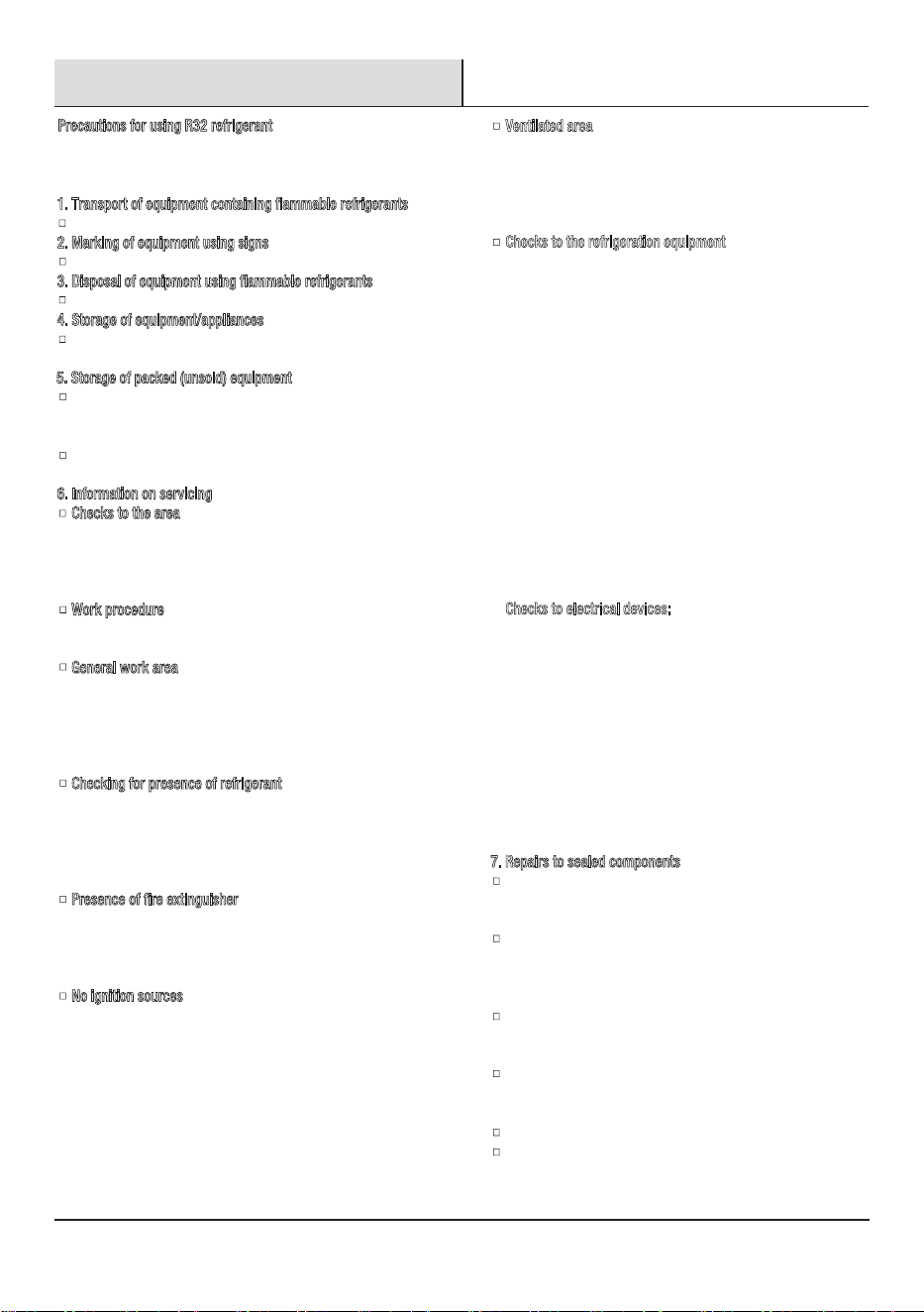
WARNING: A hazard that if not avoided could result In
death or serious Injury.
CAUTION: A hazard that if not avoided may result in
minor or moderate injury.
Explanation of symbols displayed on the unit.
Please recycle or dispose of the product packaging material in
an environmentally responsible manner.
Never store or ship the air conditioner upside down or sideways to
avoid damage to the compressor.
This appliance is not intended for use by persons (including children)
with reduced physical, sensory or mental capabilities,
or lack of experience and knowledge, unless they have been given
supervision or instruction concerning use of the appliance by a
person responsible for their safety. Children should be supervised to
ensure that they do not play with the appliance.
The wiring diagram is shown on nameplate on the air conditioner.
Location Requirements . . . . . . . . . . . . . . . . . . . . . . . . . . . . .9
Unpack The Air Conditioner . . . . . . . . . . . . . . . . . . . . . . . . . 10
Window Vent Panel and Extensions. . . . . . . . . . . . . . . . . . . 10
Installation . . . . . . . . . . . . . . . . . . . . . . . . . . . . . . . . . . . . . . . 11
Operation. . . . . . . . . . . . . . . . . . . . . . . . . . . . . . . . . . . . . . . . . 15
Care and Cleaning . . . . . . . . . . . . . . . . . . . . . . . . . . . . . . . . . 20
Troubleshooting . . . . . . . . . . . . . . . . . . . . . . . . . . . . . . . . . . . 22
Safety Information . . . . . . . . . . . . . . . . . . . . . . . . . . . . . . . . . . 2
Pre-Installation. . . . . . . . . . . . . . . . . . . . . . . . . . . . . . . . . . . . . 6
Planning Installation . . . . . . . . . . . . . . . . . . . . . . . . . . . . . . . 6
Tools Required . . . . . . . . . . . . . . . . . . . . . . . . . . . . . . . . . . . . 6
Hardware Included. . . . . . . . . . . . . . . . . . . . . . . . . . . . .
. . . . 6
Package Contents . . . . . . . . . . . . . . . . . . . . . . . . . . . . . . . . . 7
Electrical Requirements. . . . . . . . . . . . . . . . . . . . . . . . . . . . . 8
Your safety and the safety of others are very important. We have
provided many important safety messages in this manual and on your
appliance. Please always read and obey all safety messages. To reduce
conditioner,
please follow these basic precautions:
IMPORTANT SAFETY INSTRUCTIONS
Plug into a grounded 3-prong outlet.
Do not remove ground prong.
Do not use an electrical adapter.
Do not use an extension cord.
Unplug air conditioner before servicing.
Use two or more people to move and install air conditioner.
If the SUPPLY CORD is damaged, it must be replaced by the
manufacturer, its service agent or similarly qualied persons in
DISPOSING OF THE UNIT
Before throwing out the device, it is necessary to remove the battery
cells and dispose or recycle them properly.
When you need disposal of the unit consult our dealer. If pipes are
removed incorrectly, refrigerant may blow out and come into
contact with your skin, causing injury. Releasing refrigerant into
the atmosphere also damages the environments.
DANGER: A hazard that if not avoided will result In death
or serious injury.
This symbol shows that the operation manual should be
read carefully.
This symbol shows that a service personnel should be
handling this equipment with reference to the installation
manual.
This symbol shows that information is available such as
the operating manual or installation manual.
CAUTION
CAUTION
CAUTION
WARNING
an
This symbol shows that this appliance uses a ammable
refrigerant. If the refrigerant is leaked and exposed to
external ignition source, there is a risk of re.
A2L
Safety Information (continued)
The basic installation work procedures are the same as the
conventional refrigerant (R22 or R410A).However, pay attention to
the following :
1
. Transport of equipment containing flammable refrigerants
Compliance with the transport regulations.
2
. Marking of equipment using signs
Compliance with local regulations.
3
. Disposal of equipment using flammable refrigerants
Compliance with national regulations.
4
. Storage of equipment/appliances
The storage of equipment should be in accordance with the
manufacturer
5
. Storage of packed (unsold) equipment
Storage package protection should be constructed such that
mechanical damage to the equipment inside the package will
not cause a leak of the refrigerant charge.
The maximum number of pieces of equipment permitted to be
stored together will be determined by local regulations.
6
. Information on servicing
Checks to the area: Prior to beginning work on systems
containing ammable refrigerants, safety checks are necessary
to ensure that the risk of ignition is minimised. For repair to the
refrigerating system, the following precautions shall be
complied with prior to conducting work on the system.
W
ork procedure: Work shall be undertaken under a controlled
procedure so as to minimise the risk of ammable gas or
vapour being present while the work is being performed.
G
eneral work area: All maintenance staff and others working in
the local area shall be instructed on the nature of work being
carried out. Work in conned spaces shall be avoided. The area
around the workspace shall be sectioned off. Ensure that the
conditions within the area have been made safe by control of
ammable material.
C
hecking for presence of refrigerant: The area shall be checked
with an appropriate refrigerant detector prior to and during
work, to ensure the technician is aware of potentially ammable
atmospheres. Ensure that the leak detection equipment being
used is suitable for use with ammable refrigerants, i.e. non-
sparking, adequately sealed or intrinsically safe.
P
resence of fire extinguisher: If any hot work is to be conducted
on the refrigeration equipment or any associated parts,
appropriate re extinguishing equipment shall be available to
hand. Have a dry powder or CO2 re extinguisher adjacent to
the charging area.
N
o ignition sources: No person carrying out work in relation to
a refrigeration system which involves exposing any pipe work
that contains or has contained ammable refrigerant shall use
any sources of ignition in such a manner that it may lead to the
risk ofre or explosion. All possible ignition sources, including
cigarette smoking, should be kept sufciently far away from the
site of installation, repairing, removing anddisposal, during
which ammable refrigerant can possibly be released to the
surrounding space. Prior to work taking place, the area around
the equipment is to be surveyed to make sure that there are no
ammable hazards or ignition risks.“No Smoking”signs shall be
displayed.
's instructions.
7. Repairs to sealed components
During repairs to sealed components, all electrical supplies shall
be disconnected from the equipment being worked upon prior
to any removal of sealed covers, etc.
If it is absolutely necessary to have an electrical supply to
equipment during servicing, then a permanently operating form
of leak detection shall be located at the most critical point to
warn of a potentially hazardous situation.
Particular attention shall be paid to the following to ensure that
by working on electrical components, the casing is not altered
in such a way that the level of protection is affected.
This shall include damage to cables, excessive number of
connections,terminals not made to original specication,
damage to seals,
Ensure that apparatus is mounted securely.
Ensure that seals or sealing materials have not degraded such
that they no longer serve the purpose of preventing the ingress
of ammable atmospheres.
incorrect tting of glands, etc.
Precautions for using R32 refrigerant
3
Ventilated area: Ensure that the area is in the open or that it is
adequately ventilated before breaking into the system or
conducting any hot work. A degree of ventilation shall continue
during the period that the work is carried out. The ventilation
should safely disperse any released refrigerant and preferably
expel it externally into the atmosphere.
C
hecks to the refrigeration equipment: Where electrical
components are being changed, they shall be t for the purpose
and to the correct specication. At all times the manufacturer's
maintenance and service guidelines shall be followed. If indoubt
consult the manufacturer's technical department for assistance.
The following checks shall be applied to installations using
ammable refrigerants: The charge size is in accordance with
the room size within which the refrigerant containing parts are
installed; The ventilation machinery and outlets are operating
adequately and are not obstructed; If an indirect refrigerating
circuit is being used, the secondary circuit shall be checked for
the presence of refrigerant; Marking to the equipment continues
to be visible and legible. Markings and signs that are illegible
shall be corrected; Refrigeration pipe or components are
installed in a position where they are unlikely to be exposed to
any substance which may corrode refrigerant containing
components, unless the components are constructed of
materials which are inherently resistant to being corroded or
are suitably protected against being so corroded.
C
hecks to electrical devices: Repair and maintenance to
electrical components shall include initial safety checks and
component inspection procedures. If a fault exists that could
compromise safety, then no electrical supply shall be connected
to the circuit until it is satisfactorily dealt with. If the fault
cannot be corrected immediately but it is necessary to continue
operation, an adequate temporary solution shall be used.
This shall be reported to the owner of the equipment so all
parties are advised. Initial safety checks shall include: That
capacitors are discharged: this shall be done in a safe manner
to avoid possibility of sparking; That there no live electrical
components and wiring are exposed while charging, recovering
or purging the system; That there is continuity of earth bonding.
4
Safety Information (continued)
Replacement parts shall be in accordance with the manufacturer's
specications.
8. Repairs to intrinsically safe components
9. Cabling
Check that cabling will not be subject to wear, corrosion,
excessive pressure,vibration, sharp edges or any other adverse
environmental effects.
The check shall also take into account the effects of aging or
continual vibration from sources such as compressors or fans.
10. Detection of flammable refrigerants
Under no circumstances shall potential sources of ignition be used
in these arching for or detection of refrigerant leaks.
Ahalide torch (or any other detector using a naked ame) shall not
be used.
1
1. Leak detection methods
The following leak detection methods are deemed acceptable for
systems containing ammable refrigerants:
Electronic leak detectors shall be used to detect ammable
refrigerants, but the sensitivity may not be adequate, or may need
re-calibration. (Detection equipment shall be calibrated in a
refrigerant-free area.)
Ensure that the detector is not a potential source of ignition and
is suitable for the refrigerant used.
Leak detection equipment shall be set at a percentage of the
LFL of the refrigerant and shall be calibrated to the refrigerant
employed and the appropriate percentage of gas (25 % maximum)
is conrmed.
Leak detection uids are suitable for use with most refrigerants
but the use of detergents containing chlorine shall be avoided as
the chlorine may react with the refrigerant and corrode the copper
pipe-work.
If a leak is suspected, all naked ames shall be removed/
extinguished.
If a leakage of refrigerant is found which requires brazing, all
of the refrigerant shall be recovered from the system, or isolated
(by means of shutoff valves) in a part of the system remote from
the leak.
Oxygen free nitrogen (OFN) shall then be purged through the
system both before and during the brazing process.
1
2. Removal and evacuation
When breaking into the refrigerant circuit to make repairs - or for
any other purpose - conventional procedures shall be used.
However , for ammable refrigerants it is important that best
14.Decommissioning
a) Become familiar with the equipment and its operation.
b) Isolate system electrically.
c) Before attempting the procedure ensure that:
–Mechanical handling equipment is available, if required,
Before carrying out this procedure, it is essential that the technician
is completely familiar with the equipment and all its detail.
It is recommended good practice that all refrigerants are recovered
safely.
Prior to the task being carried out, an oil and refrigerant sample
shall be taken in
case analysis is required prior to re-use of
reclaimed refrigerant. It is essential that electrical power is
available
before the task is commenced.
NOTE: The use of silicon sealant may inhibit the effectiveness
of some types of leak detection equipment. Intrinsically safe
components do not have to be isolated prior to working on them.
Do not apply any permanent inductive or capacitance loads to the
circuit without ensuring that this will not exceed the permissible
voltage and current permitted for the equipment in use.
Intrinsically safe components are the only types that can be worked
on while live in the presence of a ammable atmosphere. The test
apparatus shall be at the correct rating.
Replace components only with parts specied by the manufacturer.
Other parts may result in the ignition of refrigerant in the
atmosphere from a leak.
practice be followed , since ammability is a consideration.
The following procedure shall be adhered to :
a) safely remove refrigerant following local and national
regulations ;
b) purge the circuit with inert gas ;
c) evacuate ( optional for A2L);
d) purge with inert gas ( optional for A2L);
e) open the circuit by cutting or brazing;
The refrigerant charge shall be recovered into the correct recovery
cylinders if venting is not allowed by local and national codes.
For appliances containing ammable refrigerants, the systemshall
be purged with oxygen - free nitrogen to render theappliance safe
for ammable refrigerants. This process mightneed to be repeated
several times. Compressed air or oxygen
shall not be used for purging refrigerant systems.
For appliances containing ammable refrigerants, refrigerants
purging shall be achieved by breaking the vacuum in the system
with oxygen - free nitrogen and continuing to ll until the working
pressure is achieved, then venting to atmosphere, and nally
pulling down to a vacuum ( optional for A2L). This process shall
be repeated until no refrigerant is within the system ( optional
for A2L). When the nal oxygen - free nitrogen charge is used,
the system shall be vented down to atmospheric pressure to
enable work to take place.
Ensure that the outlet for the vacuum pump is not close to any
potential ignition sources and that ventilation is available.
1
3. Charging procedures
A follow up leak test shall be carried out prior to leaving the site.
In addition to conventional charging procedures, the following
requirements shall be followed:
–Ensure that contamination of different refrigerants does not
occur when using charging equipment.
–Hoses or lines shall be as short as possible to minimise the
amount of refrigerant contained in them.
–Cylinders shall be kept up right.
–Ensure that the refrigeration system is earthed prior to
charging the system with refrigerant.
–Label the system when charging is complete (if not already).
–Extreme care shall be taken not to overll the refrigeration
system.
Prior to recharging the system it shall be pressure tested with OFN.
The system shall be leak tested on completion of charging but
prior to commissioning.
Safety Information (continued)
for handlingrefrigerantcylinders;
–All personal protective equipment is available and being used
correctly;
–The recovery process is supervised at all times by a competent
person;
–Recovery equipment and cylinders conform to the appropriate
standards.
d) Pump down refrigerant system, if possible.
e) If a vacuum is not possible, make a manifold so that refrigerant
can be removed from various parts of the system.
f) Make sure that cylinder is situated on the scales before recovery
takes place.
g) Start the recovery machine and operate in accordance with
manufacturer
h) Do not overll cylinders. (No more than 80 % volume liquid
charge).
i) Do not exceed the maximum working pressure of the cylinder,
even temporarily.
j) When the cylinders have been lled correctly and the process
completed, make sure that the cylinders and the equipment are
removed from site promptly and all isolation valves on the
equipment are closed off.
k) Recovered refrigerant shall not be charged into another
refrigeration system unless it has been cleaned and checked.
1
5. Labelling
Equipment shall be labelled stating that it has been de-
commissioned and emptied of refrigerant.
's instructions.
The label shall be dated and signed.
Ensure that there are labels on the equipment stating the
equipment
1
6.Recovery
When removing refrigerant from a system, either for servicing
or decommissioning, it is recommended good practice that all
refrigerants are removed safely.
When transferring refrigerant into cylinders, ensure that only
appropriate refrigerant recovery cylinders are employed.
Ensure that the correct number of cylinders for holding the total
system charge is available.
All cylinders to be used are designated for the recovered
refrigerant and labelled for that refrigerant (i.e. special cylinders
for the recovery of refrigerant).
Cylinders shall be complete with pressure relief valve and
associated shut-off valves in good working order.
Empty recovery cylinders are evacuated and, if possible, cooled
before recovery occurs.
The recovery equipment shall be in good working order with a
set of instructions concerning the equipment that is at hand and
shall be suitable for the recovery of ammable refrigerants.
In addition, a set of calibrated weighing scales shall be available
and in good working order.
Hoses shall be complete with leak-free disconnect couplings and
in good condition.
contains ammable refrigerant.
5
Consult manufacturer if in doubt.
Opening of the refrigeration systems shall not be done by
brazing.
The recovered refrigerant shall be returned to the refrigerant
supplier in the correct recovery cylinder, and the relevant Waste
Transfer Note arranged.
Do not mix refrigerants in recovery units and especially not in
cylinders.
If compressors or compressor oils are to be removed, ensure
that they have been evacuated to an acceptable level to make
certain that ammable refrigerant does not remain within the
lubricant.
The evacuation process shall be carried out prior to returning
the compressor to the suppliers.
Only electric heating to the compressor body shall be employed
to accelerate this process.
When oil is drained from a system, it shall be carried out safely.
Before using the recovery machine, check that it is in satisfactory
working order, has been properly maintained and that any
associated electrical components are sealed to prevent ignition
in the event of a refrigerant release.
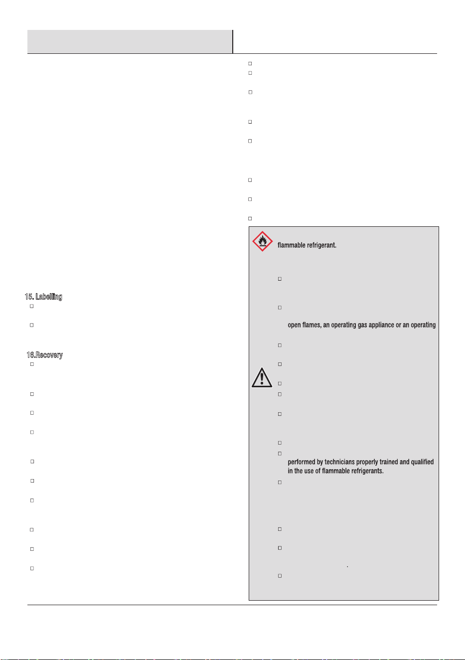
WARNING: Risk of Fire or Explosion. This unit contains
Additional safety precautions must be followed.
Do not use means to accelerate the defrosting process
or to clean, other than those recommended by the
manufacturer.
The appliance shall be stored in a room without
continuously operating ignition sources (for example:
electric heater).
Do not pierce or burn refrigerant tubing. Be aware that
refrigerants may not contain an odor.
Keep ventilation openings clear of obstruction.
The maximum refrigerant charge amount is shown on
nameplate on the air conditioner.
When handling, installing, and operating the appliance,
care should be taken to avoid damage to the refrigerant
tubing.
Do not drill holes in the unit.
Maintenance, cleaning, and service should only be
Dispose of air conditioner in accordance with Federal
and Local Regulations. Flammable refrigerants require
special disposal procedures. Contact your local
authorities for the environmentally safe disposal of your
air conditioner.
The appliance shall be stored so as to prevent
mechanical damage from occurring.
This product contains small parts such as (batteries,
battery cover and screws) that may cause suffocation
if swallowed by children.
The appliance shall be stored in a well-ventilated area
where the room size corresponds to the room area as
specied for operation
Compliance with national gas regulations shall be
observed.
A2L
Pre-Installation
PLANNING INSTALLATION
Gather the required tools and parts before starting installation. Check that all parts are included in parts package. Read and follow the
instructions provided with any tools listed here.
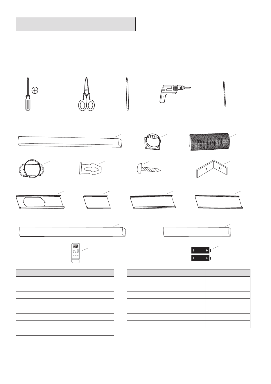
TOOLS REQUIRED
Phillips
screwdriver
Scissors Pencil
Cordless
drill
1/8 in. bit
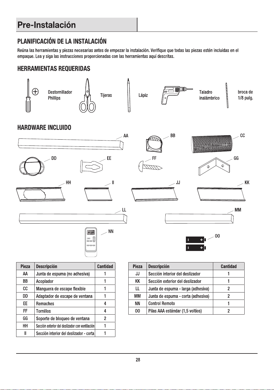
HARDWARE INCLUDED
AA
BB CC
DD EE FF GG
HH II JJ KK
LL
NN
OO
MM
Part Description Quantity Part Description Quantity
AA Foam seal (non-adhesive) 1 II Inner slider section-short 1
BB Coupling 1 JJ Inner slider section 1
CC Flexible exhaust hose 1 KK Outer slider section 1
DD Window exhaust adapter 1 LL Foam seal-long (adhesive) 2
EE Rivets 4 MM Foam seal-short (adhesive) 2
FF Screws 4 NN 1
GG Window lock bracket 2 OO Standard AAA (1.5 volt) batteries 2
HH Outer slider section with vent 1
6
Remote control
MODE FAN
TIMER DIMMER
Sleep [ 5 sec ]
SWING
F / C [ 5 sec ]
Pre-Installation (continued)
PACKAGE CONTENTS
7
NOTE:
Mercury free super heavy duty R03 UM-4 size AAA 1.5V.
Best used before date code (month-year) on the bottom.
Caution for ingestion: the battery may cause suffocation if swallowed by children.
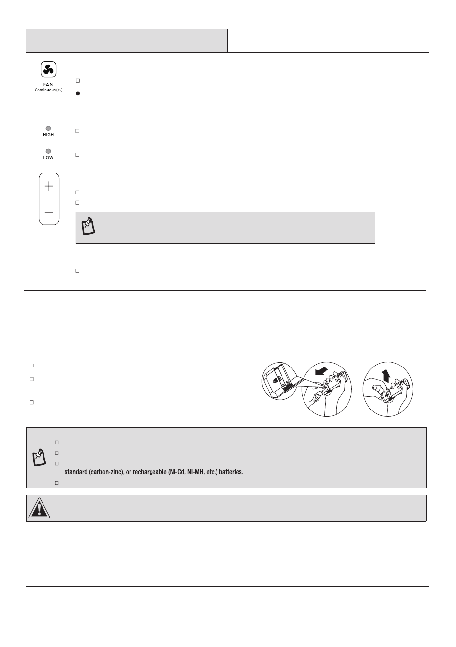
Do not mix old and new batteries. Do not mix alkaline, standard (carbon - zinc), or rechargeable (nickel - cadmium) batteries.
Non-rechargeable batteries are not to be recharged.
Exhausted batteries are to be removed from the product.
DO NOT DISPOSE OF BATTERIES IN FIRE. BATTERIES MAY EXPLODE OR LEAK.
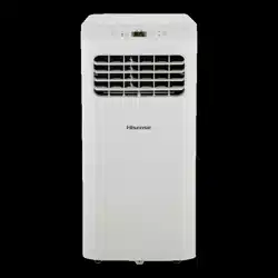
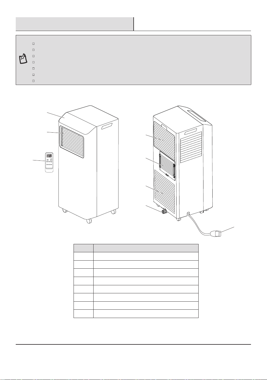
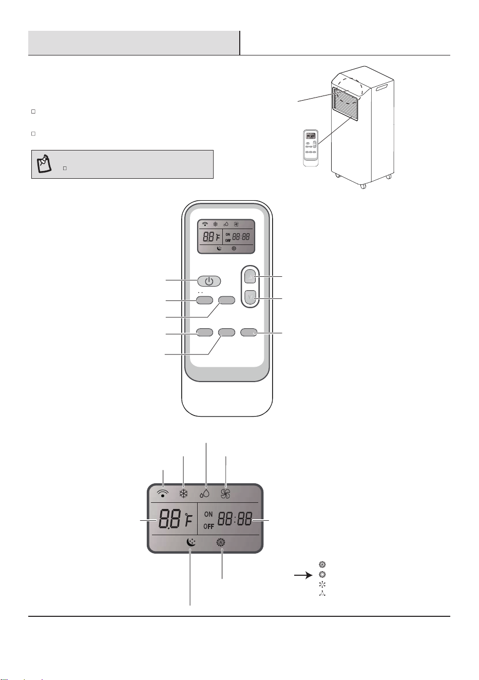
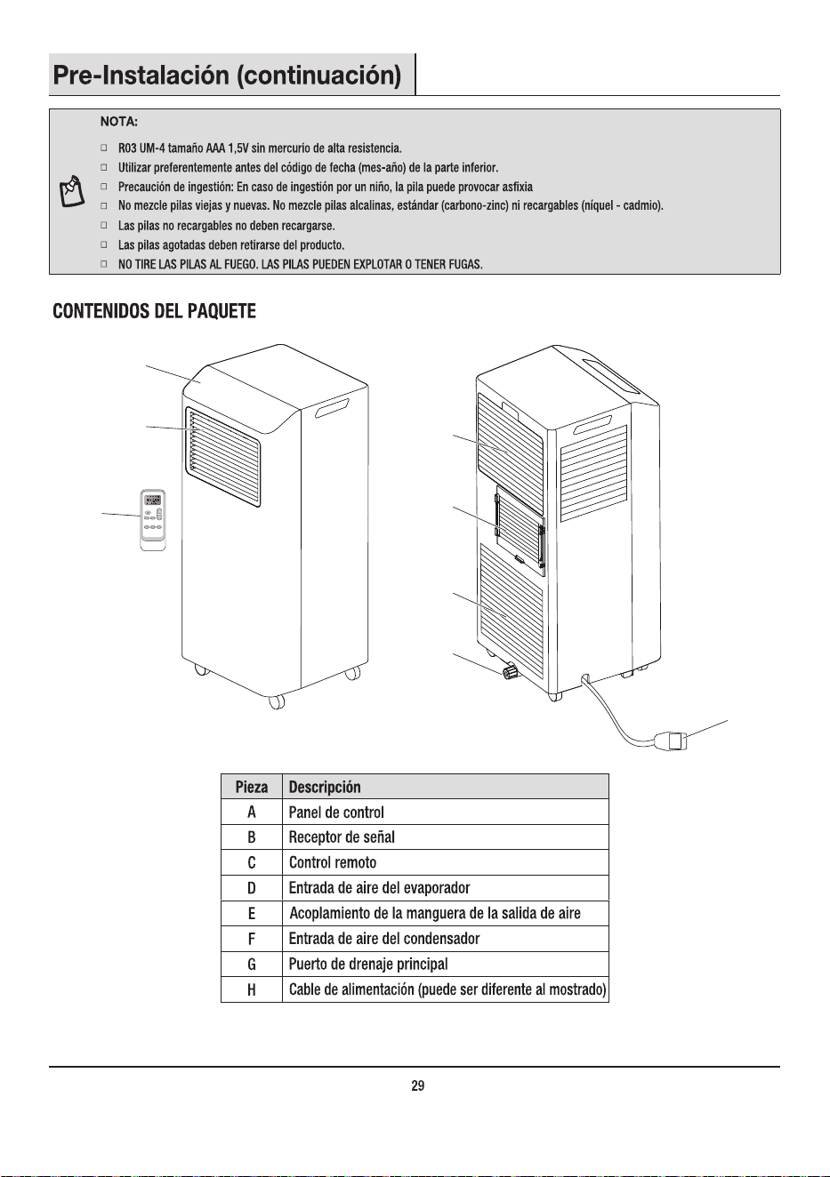
Part Description
A Control panel
B
C
Cool air outlet
D
Remote control
E
F
Evaporator air intake
G
Air outlet hose coupling
H
Condenser air intake
Primary drain port
Power cord (may differ from the one shown)
H
D
E
F
G
A
B
C
MODE FAN
TIMER DIMMER
Sleep [ 5 sec ]
SWING
F / C [ 5 sec ]
Pre-Installation (continued)
ELECTRICAL REQUIREMENTS
Recommended Grounding Method
This portable air conditioner must be grounded. This portable air conditioner is equipped with a power supply cord with a three-prong
grounding plug. The cord must be plugged into a properly grounded three-prong outlet, grounded in accordance with all local codes and
ordinances. If a properly grounded outlet is not available, it is the customer’s responsibility to have a properly grounded three-prong outlet
Customer’s Responsibility
To assure that the electrical installation is adequate and conforms to the national electrical code, ANSI/NFPA 70-last edition, and all
local codes and ordinances.
Copies of the standards listed may be obtained from:
National Fire Protection Association
1 Batterymarch Park
Quincy, MA 02169-7471
www.nfpa.org
Wiring Requirement
Power supply Model Time-delay fuse (or circuit breaker)
115V
103.5V min.
126.5V max.
5KBTU 10A
6KBTU 13A
Power Supply Cord
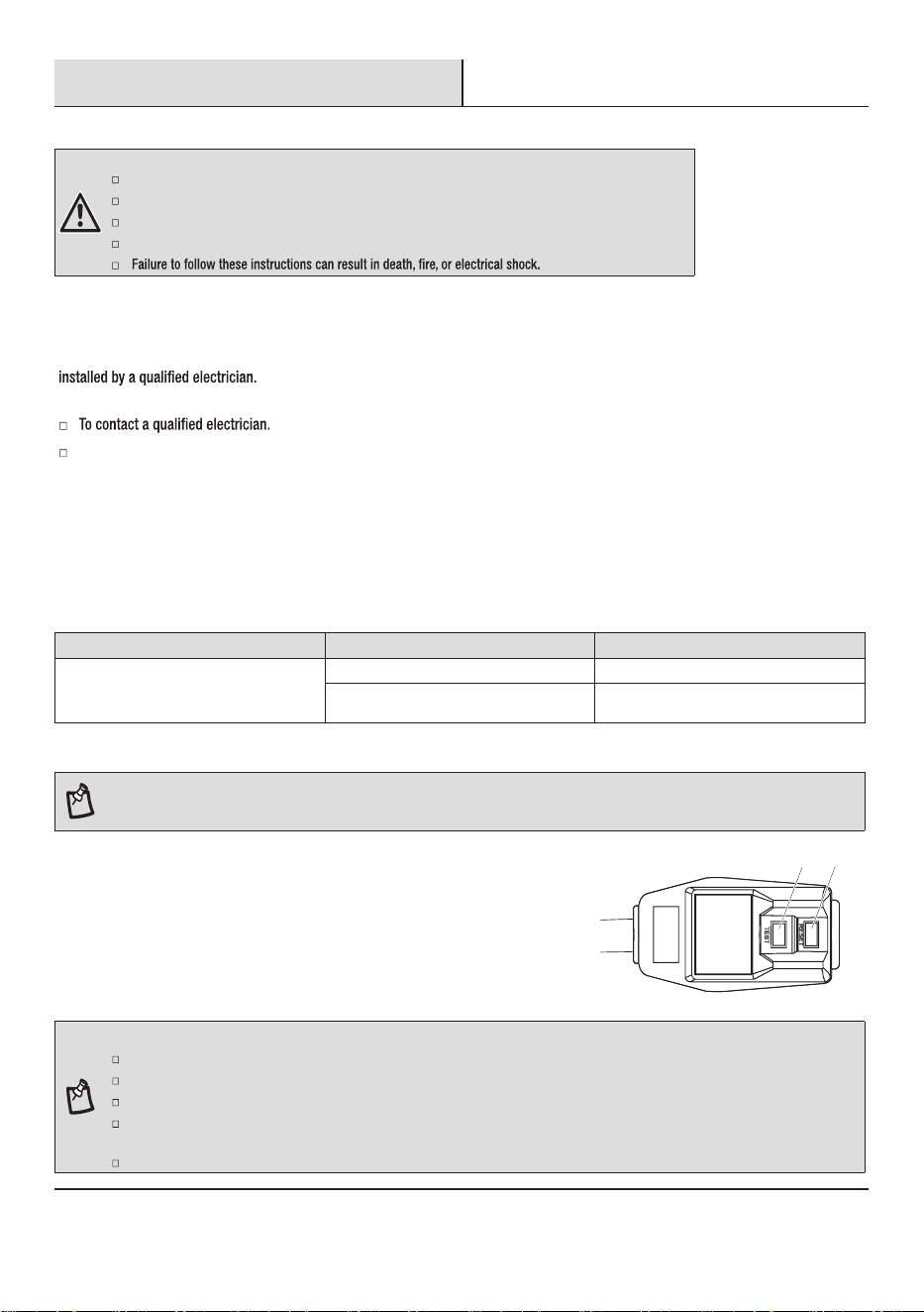
NOTE: Your air conditioner’s device may differ from the one shown. This room air conditioner is equipped with a power supply cord required
by UL. This power supply cord contains state-of-the-art electronics that sense leakage current. If the cord is crushed, the electronics detect
leakage current and power will be disconnected in a fraction of a second.
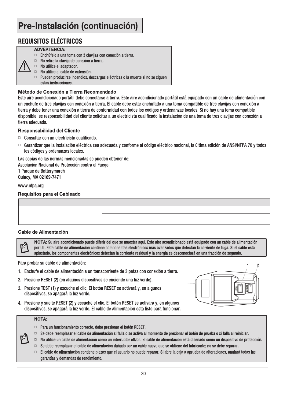
To test your power supply cord:
1. Plug power supply cord into a grounded 3-prong outlet.
2. Press RESET (2) (on some devices, a green light will turn on).
3. Press TEST (1) and listen for click. The RESET button will trip, and on some devices, a
green light will turn off.
4. Press and release RESET (2) and listen for click. The RESET button will latch, and on
some devices, a green light will turn on. The power supply cord is ready for operation.
1
2
8
NOTE:
The RESET button must be pushed in for proper operation.
The power supply cord must be replaced if it fails to trip when the test button is pressed or fails to reset.
Do not use the power supply cord as an off/on switch. The power supply cord is designed as a protective device.
If the SUPPLY CORD is damaged, it must be replaced by the manufacturer, its service agent or similarly qualied persons in order to
avoid a hazard.
The power supply cord contains no user serviceable parts. Opening the tamper-resistant case voids all warranty and performance claims.
WARNING:
Plug into a grounded 3-prong outlet.
Do not remove ground prong.
Do not use an adapter.
Do not use an extension cord. The appliance shall be installed in advance with national wiring regulations.
Pre-Installation (continued)
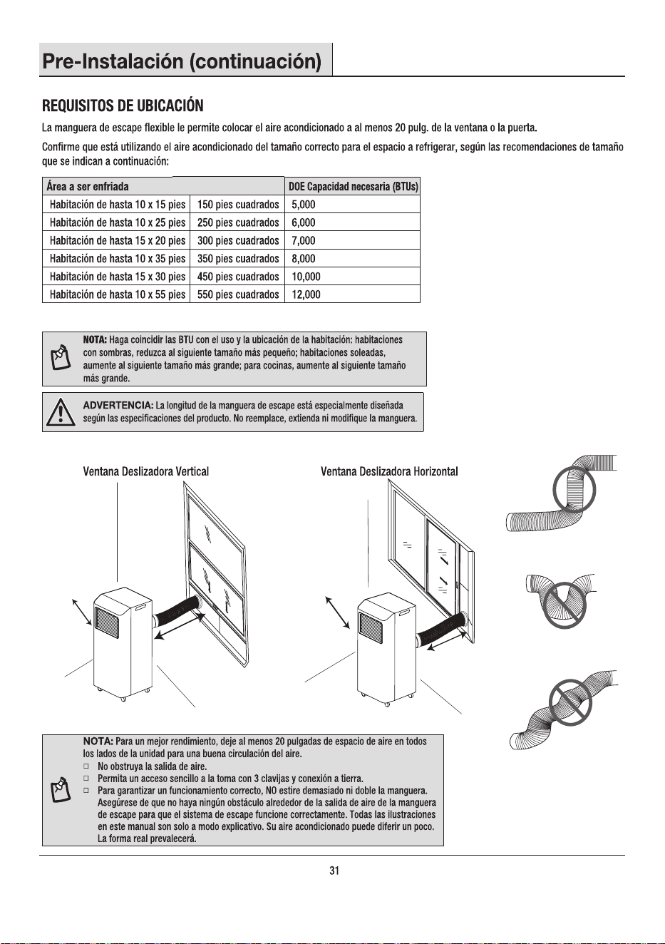
LOCATION REQUIREMENTS
Area to be cooled DOE capacity needed (BTUs)
Up to 10 ft x 15 ft room 150 sq. ft 5,000
Up to 10 ft x 25 ft room 250 sq.ft 6,000
Up to 15 ft x 20 ft room 300 sq. ft 7,000
Up to 10 ft x 35 ft room 350 sq. ft 8,000
Up to 15 ft x 30 ft room 450 sq. ft. 10,000
Up to 10 ft x 55 ft room 550 sq. ft 12,000
NOTE: Match BTUs to room use and location: shaded room, reduce to next smaller size;
sunny room, increase to next larger size; for kitchens, increase to next larger size.
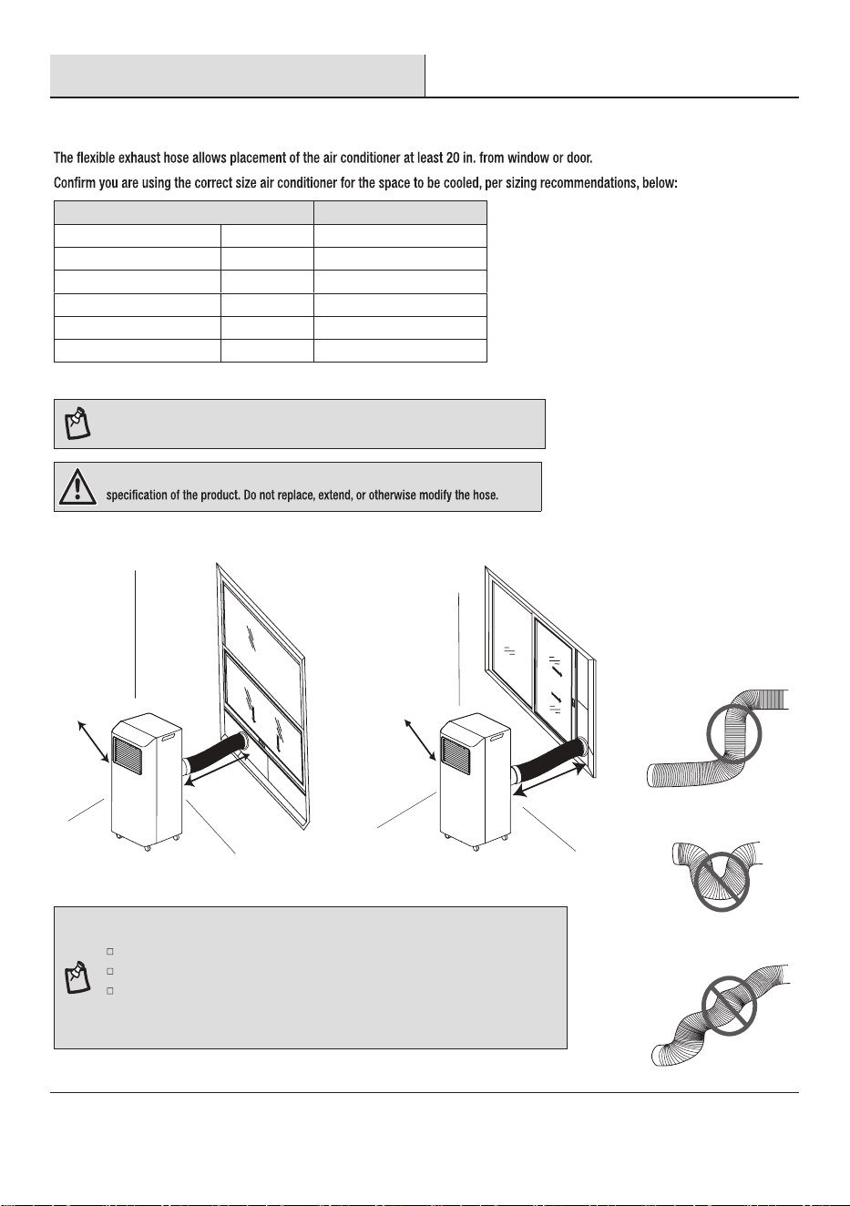
WARNING: The length of the exhaust hose is specially designed according to the
NOTE: For best performance, allow at least 20 in. of air space on all sides of the unit for good
air circulation.
Do not block the air outlet.
Provide easy access to the grounded 3-prong outlet.
To ensure proper function, DO NOT overextend or bend the hose. Make sure that there is
no obstacle around the air outlet of the exhaust hose in order for the exhaust system to
work properly. All the illustrations in this manual are for explanation purposes only. Your air
conditioner may be slightly different. The actual shape shall prevail.
9
Vertical Sliding Window
20 in.
(50 cm)
20 in.
(50 cm)
Horizontal Sliding Window
20 in.
(50 cm)
20 in.
(50 cm)
Pre-Installation (continued)
UNPACK THE AIR CONDITIONER
WARNING: Use two or more people to move and install air conditioner. Failure to do so can result in
back or other injury.
Remove Packaging Materials
Remove and recycle packaging materials.
Remove tape and glue residue from surfaces before turning on the air conditioner. Rub a small amount of liquid dish soap over the
damage the surface of your air conditioner.
Handle the air conditioner gently.
IMPORTANT: Keep unit upright at least 2 hours prior to use.
CAUTION: Installation accessories are stored in the top of the carton and are required for proper
cooling performance. Please remove all accessories from packing materials before use.
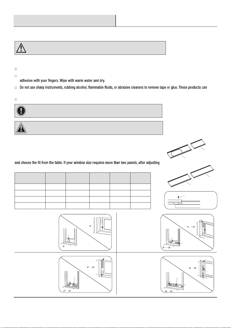
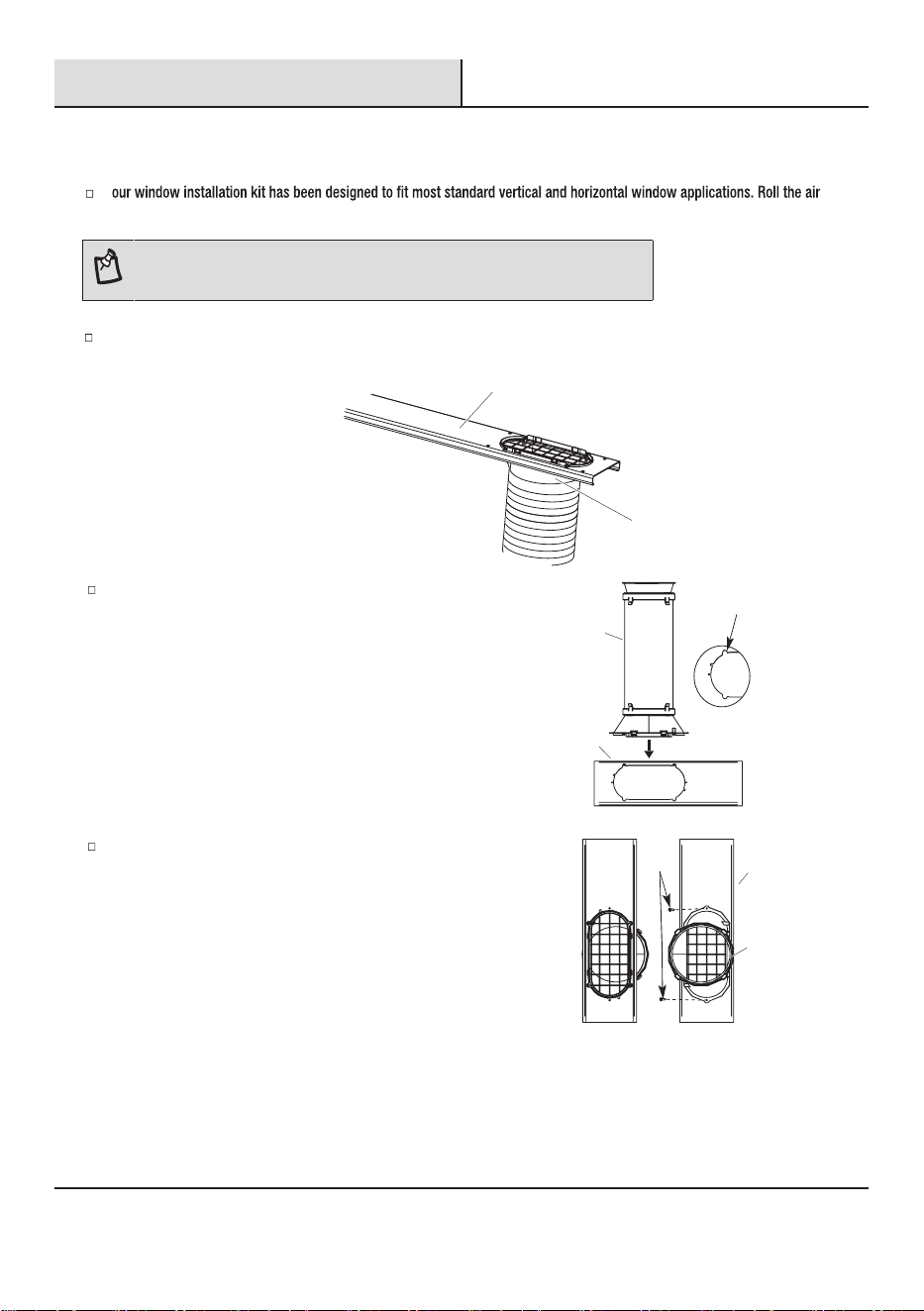
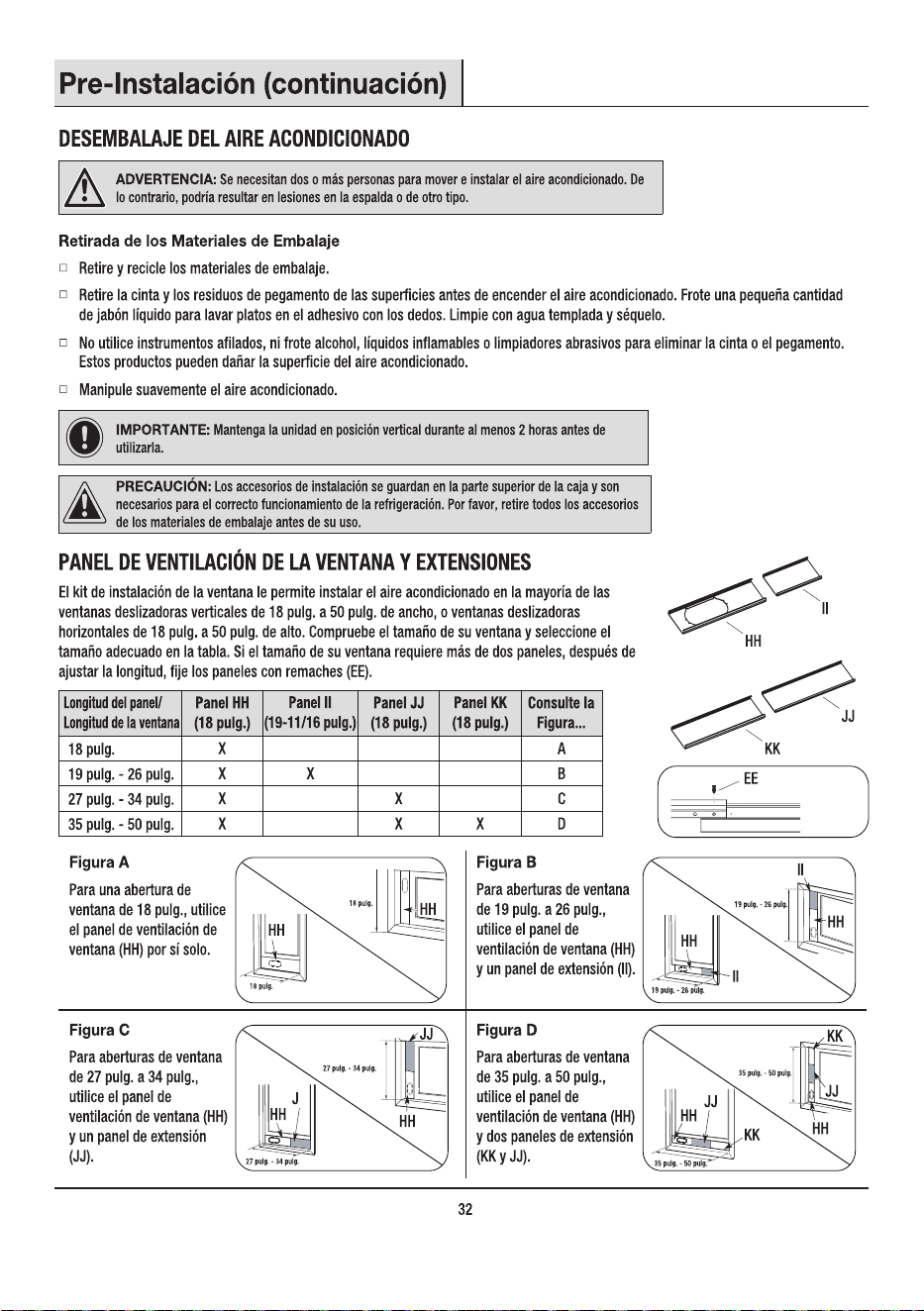
WINDOW VENT PANEL AND EXTENSIONS
The window installation kit allows you to install the air conditioner in most vertical-sliding windows
18 in. to 50 in. wide, or horizontal sliding windows from 18 in. to 50 in. tall. Check your window size
the length, please secure the panels with rivets (EE).
Panel Length /
Window Length
Panel HH
(18 in.)
Panel II
(19-11/16 in.)
Panel JJ
(18 in.)
Panel KK
(18 in.)
See
Figure...
18 in. X A
19 in. – 26 in. X X B
27 in. – 34 in. X X C
35 in. – 50 in. X X X D
Figure A
For an 18 in. window
opening, use the window
vent panel (HH) by itself.
in.
in.
HH
HH
Figure B
For window openings from
19 in. to 26 in., use the
window vent panel (HH)
and a extension panel (II).
in.
in.
in.
in.
II
II
HH
HH
Figure C
For window openings from
27 in. to 34 in., use the
window vent panel (HH)
and a extension panel (JJ).
in. in.
in. in.
HH
JJ
HH
JJ
Figure D
For window openings from
35 in. to 50 in., use the
window vent panel (HH)
and two extension panels
(KK and JJ).
in. in.
in. in.
HH
KK
JJ
HH
JJ
KK
HH
II
KK
JJ
EE
10
Installation
11
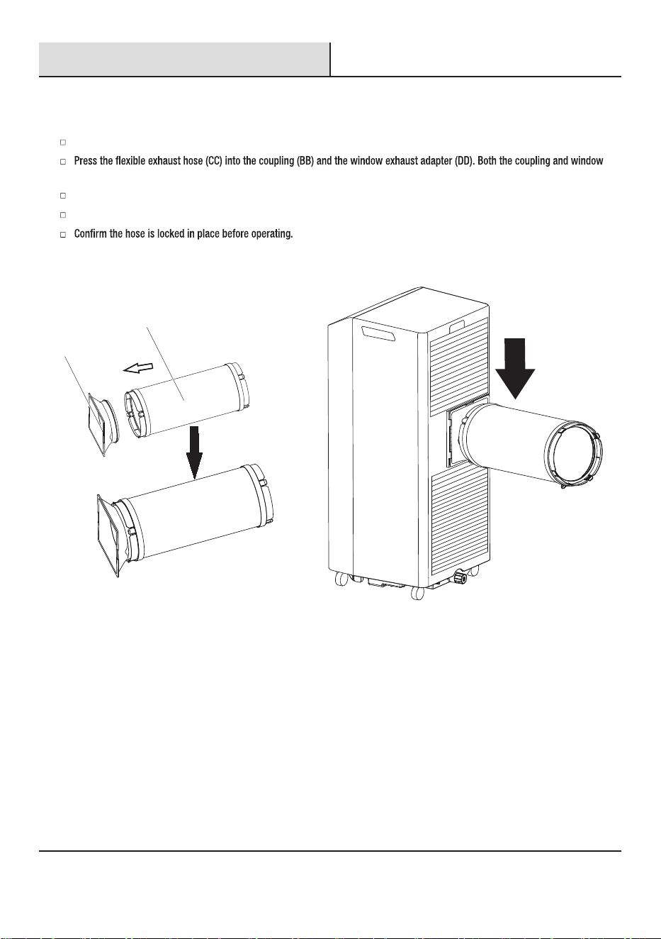
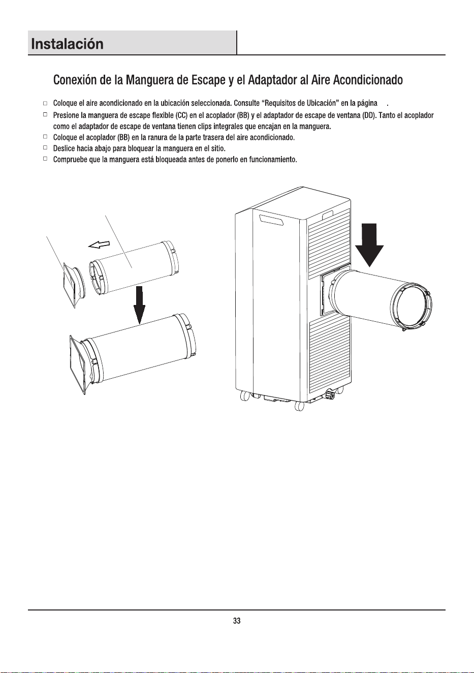
1
Attaching Exhaust Hose and Adapter to Air Conditioner
Roll the air conditioner to selected location. See “Location Requirements” on page 9.
exhaust adapter have integral clips that snap onto the hose.
Insert the coupling (BB) into the slot on the back of the air conditioner.
Slide down to lock the hose into place.
BB
CC
2
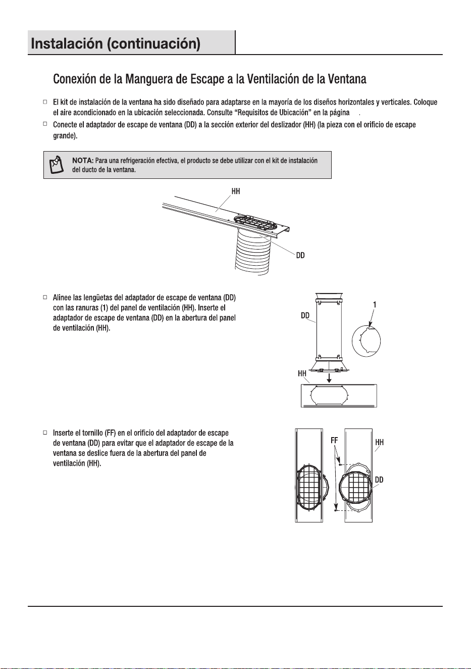
Attaching Exhaust Hose to Window Vent
Installation (continued)
Y
conditioner to selected location. See
“Location Requirements” on page 9
.
NOTE: Product must be used with included Duct Window Installation kit for effective cooling.
12
Align the tabs on the window exhaust adapter (DD) with the
slots (1) in the vent panel (HH). Insert the window exhaust
adapter (DD) into the opening in the vent panel (HH).
1
DD
HH
Insert the screw (FF) in the hole in the window exhaust
adapter (DD) to prevent the window exhaust adapter from
sliding out of the vent panel (HH) opening.
FF
DD
HH
Attach the window exhaust adapter (DD) to the outer slider section (HH) (the piece with the large exhaust hole).
HH
DD
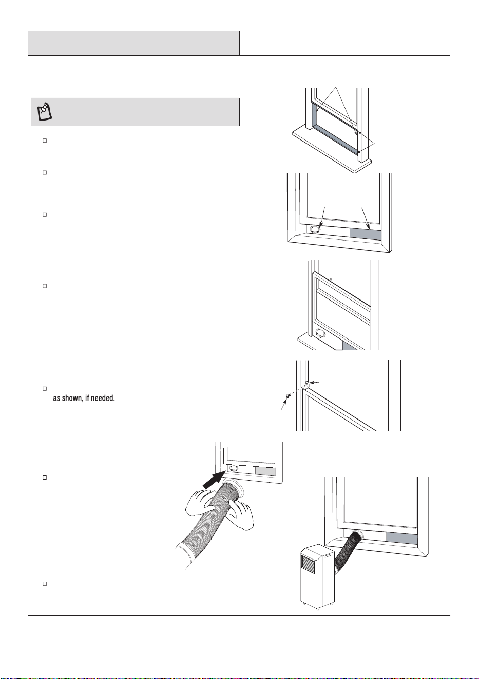
Installation (continued)
2a
Installing in Vertical Sliding Window
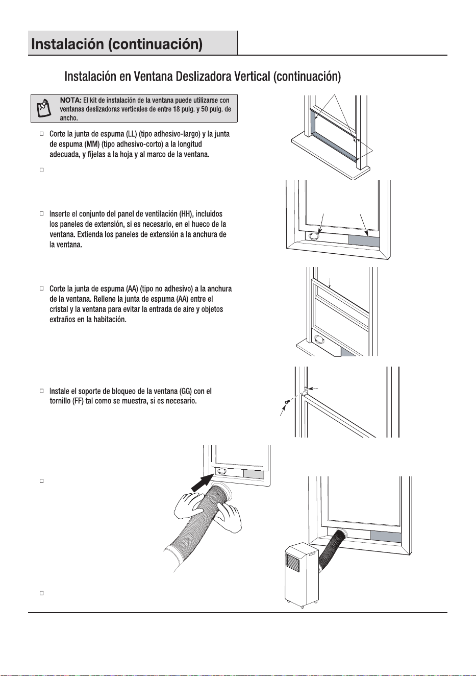
NOTE: The window installation kit can be used with vertical
sliding windows between 18 in. and 50 in. wide.
Cut the foam seal (AA) (non-adhesive type) to the window
width. Stuff the foam seal (AA) between the glass and the
window to prevent air and foreign objects from getting into
the room.
Install the window lock bracket (GG) with screw (FF)
Connect the hose to the window.
Insert the vent panel assembly (HH), including extension
panels, if needed, into the window opening. Extend the
extension panels to the window width.
13
Attach the exhaust hose to snap onto the window
exhaust adaptor.
Cut the foam seal (LL) (adhesive type-long) and foam
seal (MM) (adhesive type-shorter) to the proper
length, and attach it to the window sash and frame.
First install foam seals (MM) (shorter adhesive type) on the
left and right sides, and then install foam seals (LL) (longer
adhesive type) on the upper and lower sides.
MM
LL
AA
HH
II, JJ or KK
GG
FF
Connect the hose to the window.
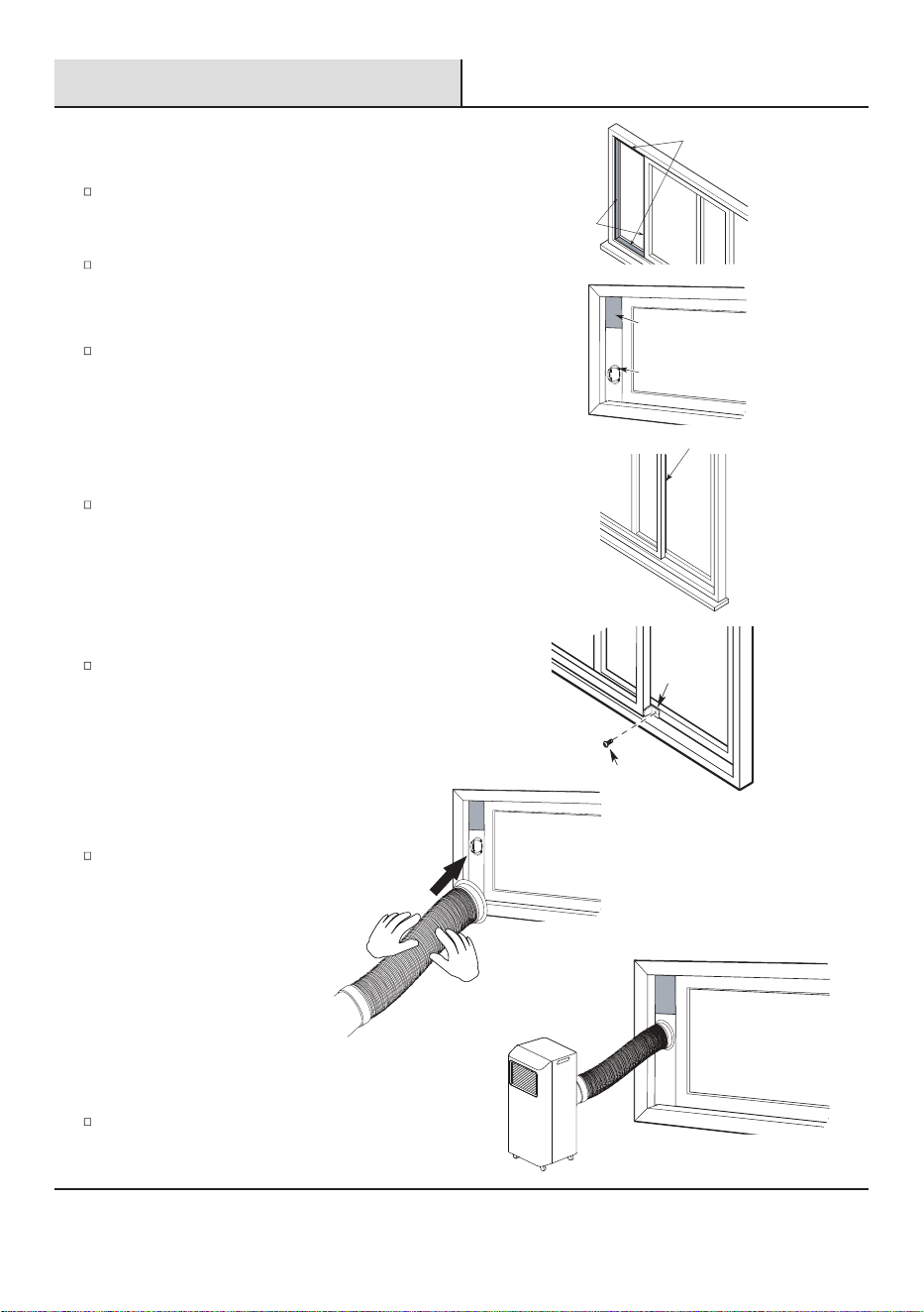
First install foam seals seals (LL) (longer adhesive type) on
the left and right sides, and then install foam (MM) (shorter
adhesive type) on the upper and lower sides.
Installation (continued)
14
AA
FF
GG
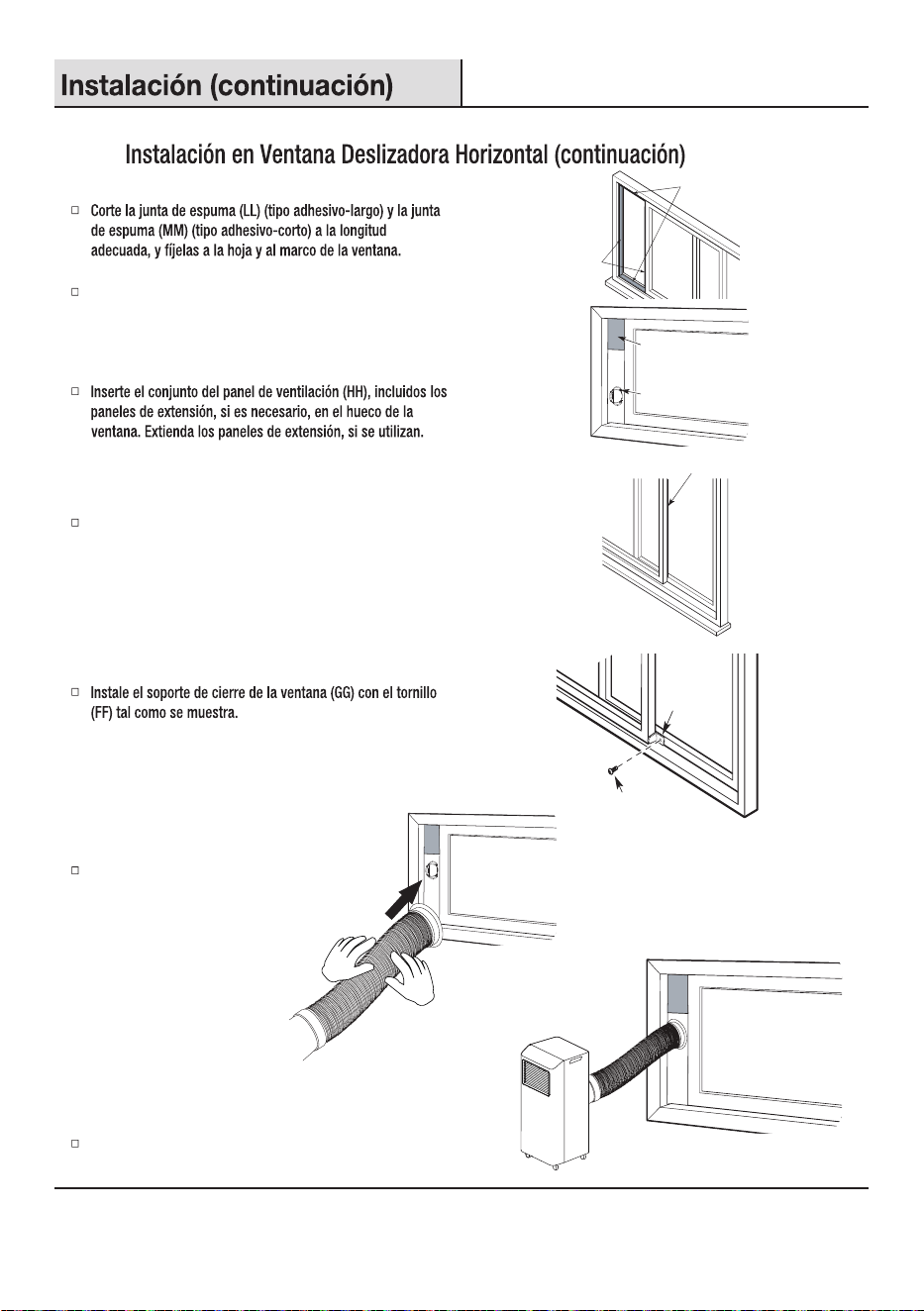
Insert the vent panel assembly (HH), including extension panels,
if needed, into the window opening. Extend the extension
panels, if used.
Install the window-lock bracket (GG) with screw (FF) as
shown.
Attach the exhaust hose to snap onto the window
exhaust adaptor.
Cut the foam seal (AA) (non-adhesive type) to the window
width. Stuff the foam seal (AA) between the glass and the
windowto prevent air and foreign objects from getting into
the room.
2b
Installing in Horizontal Sliding Window
Cut the foam seal (LL) (adhesive type-long) and foam seal
(MM) (adhesive type-shorter) to the proper length, and
attach it to the window sash and frame.
MM
LL
HH
II, JJ or KK
15
NOTE:
In the event of a power failure, your air conditioner will operate at the previous settings when the power is restored.
Operation
Operating your portable air conditioner properly helps you to obtain the best possible results. This section explains proper air conditioner operation.
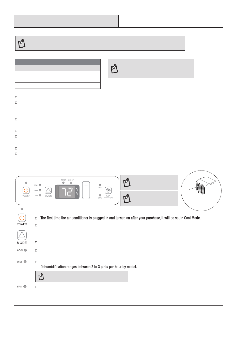
1
Using the Control Panel
NOTE: The symbols may be
different from these models,
but the functions are similar.
NOTE:
Remove the tape before use.
(valid for some models)
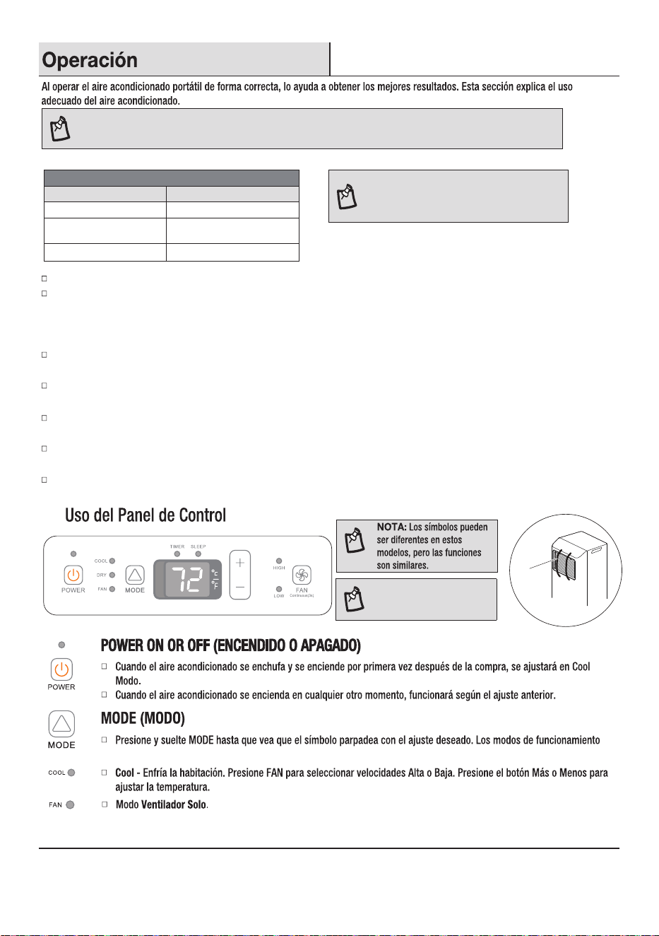
POWER ON OR OFF
When the air conditioner is turned on at all other times, it will run according to the previous setting.
MODE
Press and release MODE until you see the symbol for the desired setting. Operating modes are Cool, Dry or Fan.
Cool
- Cools the room. Press FAN to select High or Low speeds. Press the Plus or Minus button to adjust the
temperature.
Dry - Dries the room. The air conditioner automatically selects the temperature. The fan runs on Low speed only.
NOTE:
Dry mode should not be used to cool the room.
Fan Only mode. Press FAN to select High or Low.
Do not stay in direct airow from the air conditioner for extended periods of time.
Never use in tightly enclosed spaces. Always ensure there is sufcient airow of outside air entering the household especially when
used in conjunction with combustible devices such as gas stoves, replaces, furnaces, hot water heaters etc. Do not place the power
cord or air conditioner near a heater, radiator, stoves or other apparatus (including ampliers) that produce heat.
This air conditioner is intended for household use as a residential appliance. Do not use it as a precision climate control for commercial
use, or for precision equipment, food, pets, plants, artwork, etc.
Do not block or obstruct the exhaust vent hose as it may severely affect performance, or cause failure of the air conditioner.
When changing modes while the air conditioner is in operation, the compressor will stop for 3 to 5 minutes before restarting. If a button
is pressed during this time, the compressor will not restart for another 3 to 5 minutes.
In Cool
or Dry mode, the compressor and condenser fan will stop when the room temperature reaches the set temperature.
In Dry mode, the humidity level is automatically set, but is not able to be displayed.
Ambient Temperature Range For Unit Operating:
Tape
MODE Ambient Temperature Range
Cool 61-95°F (16-35°C)
Heat(pump heat mode)
41-86°F (5-30°C)
≤ 86°F(30°C)
Single hose air conditioner
Heat(electrical heat mode)
NOTE: When the DRY mode is operated at a lower
temperature, the evaporator may frost and freeze to
affect the dry effect, which is a normal phenomenon.
Operation (continued)
High
- for maximum fan speed
Low - for minimum fan speed
TEMPERATURE
Press the PLUS button once to increase the set temperature by 1 °F (1 °C).
Press the MINUS button once to decrease the set temperature by 1 °F (1 °C).
CHANGE DISPLAY BETWEEN °F AND °C
To change the temperature display between °F and °C. Press both the Plus and Minus buttons at the same time.
2
Using the Remote Control
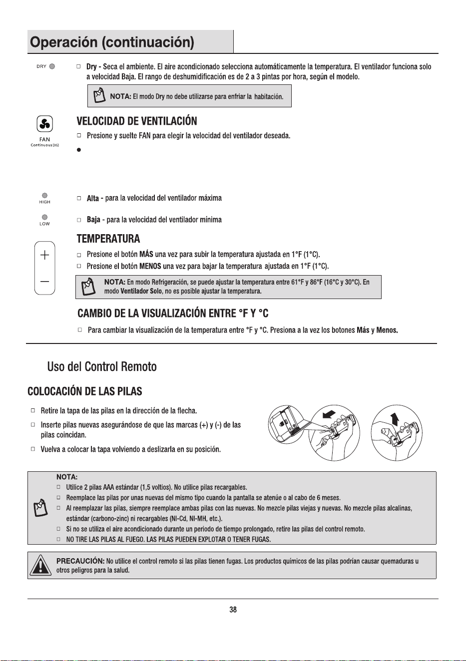
INSERT THE BATTERIES
Remove the battery cover along the arrowed direction.
Insert new batteries making sure that the (+) and (-) of battery are
matched correctly.
Reattach the cover by sliding it back into position.
NOTE:
Use 2 standard AAA (1.5 volt) batteries. Do not use rechargeable batteries.
Replace batteries with new ones of the same type when the display becomes dim, or after 6 months.
When replacing batteries, always replace both batteries with new batteries. Do not mix old and new batteries. Do not mix alkaline,
If the air conditioner will not be used for an extended period of time, remove the batteries from the remote.
CAUTION: Do not use the remote if the batteries have leaked. The chemicals in batteries could cause burns or other health hazards.
16
NOTE:
In Cooling mode, the temperature can be set between 61 °F and 86 °F (16 °C and 30 °C).
In Fan Only mode, the temperature cannot be set.
/VENT.
HIGH
/ÉLEVÉ
LOW
/FAIBLE
FAN SPEED
Press and release FAN to choose the desired fan speed.
CONTINUOUS: Press FAN and hold for 3 seconds to switch to continuous fan mode. In this mode, the
indoor fan will continue running even when the set temperature is reached. To return to the previous mode,
press and hold for 3 seconds again; the indoor fan will stop once the set temperature is reached.
Operation (continued)
17
2
Using the Remote Control (continued)
HOW TO USE
To operate the room air conditioner, aim the remote control at the
signal receptor (1).
The remote control will operate the air conditioner at a distance of up
to 23 ft. (7 m) when pointing at signal receptor of the air conditioner.
BUTTON FUNCTIONS
MODE FAN
SWING TIMER DIMMER
Sleep [ 5 sec ]
F / C [ 5 sec ]
Mode
Fan
Swing
Up
Down
Dimmer/ Sleep
Timer
On/Off
INDICATION SYMBOLS
NOTE:
Remote control may differ in appearance.
1
MODE FAN
TIMER DIMMER
Sleep [ 5 sec ]
SWING
F / C
[ 5 sec ]
Timer
Fan speed display
Cool indicator
Dry indicator
Fan only indicator
Display
set temperature
Sleep indicator
Signal transmission
Displays selected Fan speed:
Medium fan speed
Low fan speed
Auto fan speed
High fan speed
Operation (continued)
2
Using the Remote Control (continued)
18
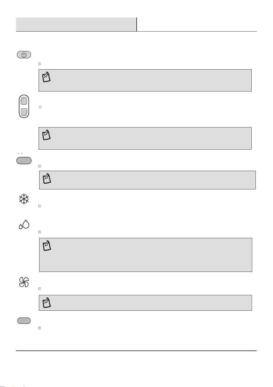
POWER ON OR OFF
NOTE:
When changing modes during operation, the unit may not respond immediately. Please be patient,
as the compressor needs 3 minutes to restart after shutting down.
Press ON/OFF button to turn on or off the unit.
NOTE: Auto fan speed cannot be selected in Fan Only mode.
FAN ONLY INDICATOR
Fan Only-Only the fan runs. Press FAN button to adjust fan speed.
COOL INDICATOR
Cooling-Cools the room. Press FAN to select AUTO, HIGH, MID or LOW.
Press the UP or DOWN button to adjust the temperature.
DRY INDICATOR
The air conditioner automatically selects the temperature. The fan runs on Low speed only.
NOTE:
In the Cooling and Heating mode, the temperature can be set between 61°F and 86°F (16°C and 30°C).
In Fan Only mode, the temperature cannot be set.
UP DOWN
MODE
Press MODE to select COOL, DRY or FAN.
NOTE:
Press the mode button for 5 seconds to switch the temperature display from degrees Fahrenheit(°F) to degrees Celsius(°C).
MODE
F / C [ 5 sec ]
FAN SPEED
Press and release FAN to choose the desired fan speed.
FAN
Press the UP or DOWN button to set the temperature.
Press the UP button once to increase the set temperature by 1 °F (1 °C).
Press the DOWN button once to decrease the set temperature by 1 °F (1 °C).
NOTE:
Dry mode should not be used to cool the room.
A decrease or rise of up to 7 °C can be set with the remote controller if you still feel uncomfortable.
Some models can decrease or rise of up to 2 °C.
Refer to the control panel of the air conditioner for the exact temperature.
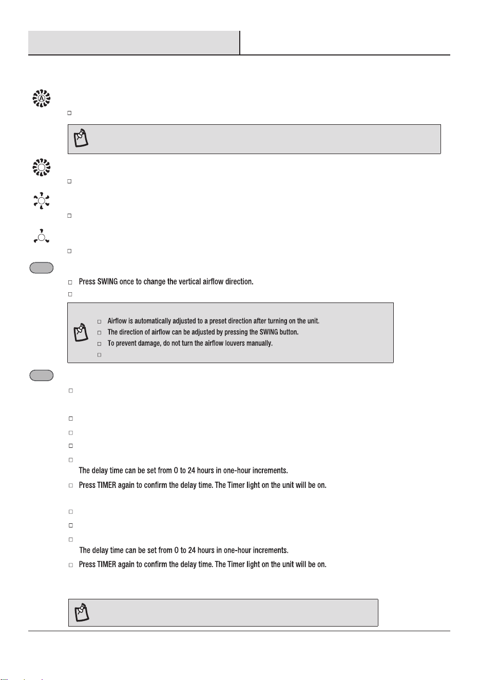
TIMER
Use the TIMER function to turn the air conditioner ON/OFF automatically.
Setting the Air Conditioner to Turn On:
Plug in the air conditioner and use the remote to power it ON.
Use the remote to set the desired mode, temperature, fan speed, etc.
Use the remote to power OFF the air conditioner.
Press TIMER on the remote and use the UP/ DOWN buttons to set the desired delay time.
Setting the Air Conditioner to Turn Off:
Plug in the air conditioner and use the remote to power it ON.
Use the remote to set the desired mode, temperature, fan speed, etc.
Press TIMER on the remote and use the UP/ DOWN buttons to set the desired delay time.
To Cancel Timer:
Press the TIMER button again. Once a “beep” is heard and the indicator disappears, the Timer mode has been canceled.
NOTE: The Timer mode can only be set by the remote control.
TIMER
Operation (continued)
2
Using the Remote Control (continued)
19
AUTO FAN SPEED
NOTE:
Auto fan speed cannot be selected in Fan Only mode.
Auto-Automatically controls fan speed depending on current room temperature and setting temperature.
HIGH FAN SPEED
High for maximum fan speed.
MEDIUM FAN SPEED
LOW FAN SPEED
Low for minimum fan speed.
Mid for normal fan speed.
SWING (NOT available for this models)
Press again to hold the louver in a desired position.
NOTE:
Turning the louver manually will disrupt normal operation. To recover, simply restart the air conditioner.
SWING
Operation (continued)
2
Using the Remote Control (continued)
20
SLEEP MODE
To turn off Sleep control, press MODE, FAN, Sleep or wait 8 hours for Sleep control to turn off automatically.
NOTE: The air conditioner will return to previous settings after Sleep mode is turned off.
Press and hold the DIMMER button on the remote for 5 seconds to switch the DIMMER mode to the Sleep mode.
After 10 seconds, the lights on the control panel display will dim.
NOTE:
Low speed.
Sleep mode can only be set in Cooling or Drying modes. When in sleep mode the unit will utilize lower, quieter fan
speeds and automatic temperature adjustments offering 8 hours of optimal sleeping conditions before shutting off.
DIMMER
Press the DIMMER button to turn off the control panel display.
NOTE: When in DIMMER mode, new control inputs will return display to normal.
DIMMER
Sleep [ 5 sec ]
DIMMER
Sleep [ 5 sec ]
3
Normal Sounds
When your air conditioner is operating normally, you may hear sounds such as:
1. Air movement from the fan.
2. Clicks from the thermostat cycling.
3. Vibration or noise due to poor wall or window construction.
4.
Scan to download the ConnectLife APP.
You can also go to Google Play or App Store and search for the ConncetLife APP.
Follow the in-APP instructions to pair your appliance.
The Connectlife app by Hisense provides you the ability to conveniently
monitor the unit and change your settings from anywhere.
DEVICES REQUIRED TO USE THE SMART AC:
Smartphone with compatible iOS or Android syste
m.
Wireless Router (a 2.4 GHz network is required to connect).
Smart air conditioner.
DOWNLOAD AND INSTALL THE CONNECTLIFE APP
4
Using the ConncetLife APP
NOTE: Only available on wi models.
NOTE: The appliance will stop operation automatically after operating for 8 hours. Fan speed is automatically set at low speed.
In the Cooling mode, if the current room temperature is below 79 °F (26 °C), the temperature will automatically increase 2 °F
is 79 °F (26 °C) or above, set temperature will not change.
In Heating mode, the set temperature will decrease by 6 °F (3 °C) at most, during 3 hours, and continues running at that
temperature until auto shut off.
Sleep control cannot be selected in Fan mode.
Care and Cleaning
1
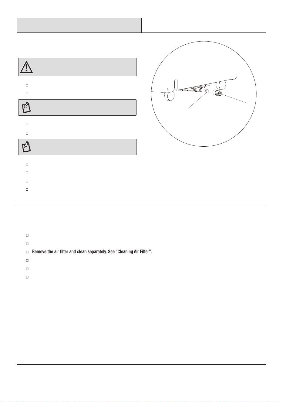
Draining the Air Conditioner
WARNING: Excessive Weight Hazard
Use two or more people to move and install the air
conditioner. Failure to do so can result in back or other injury.
Unplug the air conditioner or disconnect power.
Move the air conditioner to a drain location or outside.
NOTE: To avoid leaking water from the unit, move the air
conditioner slowly and keep it level.
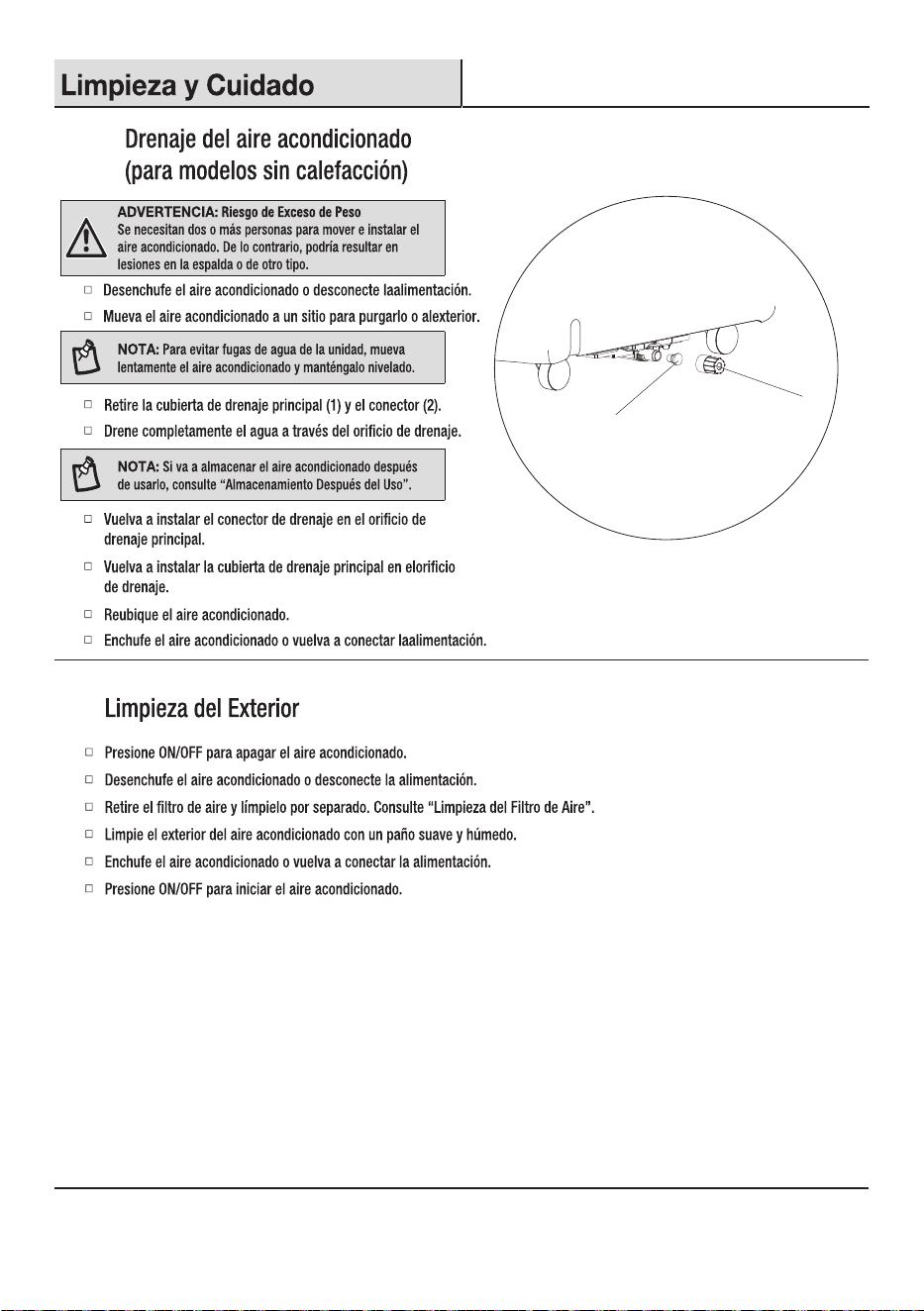
Remove the primary drain cover (1) and plug (2).
Drain water completely through the drain hole.
NOTE: If the air conditioner will be stored after use, see
“Storing After Use”.
Reinstall the drain plug to the primary drain hole.
Reinstall the primary drain cover to the drain hole.
Reposition the air conditioner.
Plug in the air conditioner or reconnect power.
2
Cleaning the Outside
Press ON/OFF to turn off the air conditioner.
Unplug air conditioner or disconnect power.
Wipe the outside of the air conditioner with a soft, damp cloth.
Plug in the air conditioner or reconnect power.
Press ON/OFF to start the air conditioner.
20
2
1
Care and Cleaning (continued)
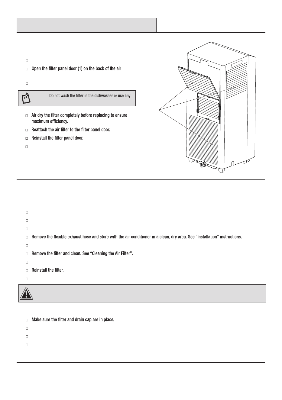
3
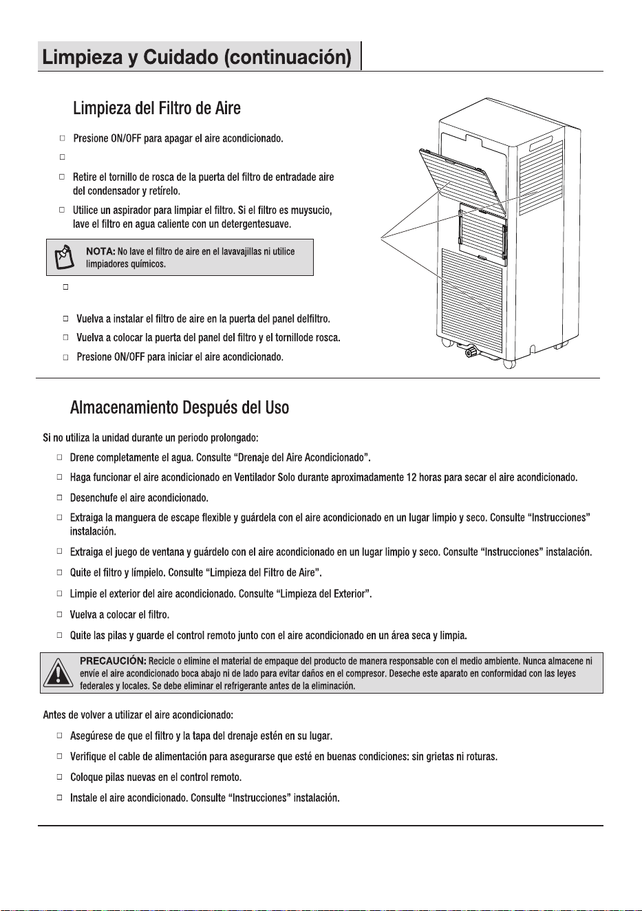
Cleaning the Air Filter
Press ON/OFF to turn off the air conditioner.
Remove the Air Filter.
conditioner and remove.
NOTE:
chemical cleaner.
Press ON/OFF to start the air conditioner.
4
Storing After Use
CAUTION: Please recycle or dispose of the packaging material for product in an environmentally responsible manner. Never store or ship the
air conditioner upside down or sideways to avoid damage to the compressor. Dispose of this appliance in accordance with Federal and Local
regulations. Refrigerants must be evacuated before disposal.
21
If the air conditioner will not be used for an extended period of time:
Drain the water completely. See “Draining the Air Conditioner”.
Run the air conditioner set to Fan Only for approximately 12 hours to dry the air conditioner.
Unplug the air conditioner.
Remove the window kit and store with the air conditioner in a clean, dry area. See “Installation” instructions.
Clean the outside of the air conditioner. See “Cleaning the Outside”.
Remove the batteries and store the remote control with the air conditioner in a clean, dry area.
Before using the air conditioner again:
Check the power cord to make sure it is in good condition, with no cracks or damage.
Place new batteries in the remote.
Install the air conditioner. See “Installation” instructions.
Air Filter
Troubleshooting
Before calling for service, please try the suggestions below.
Problem Solution
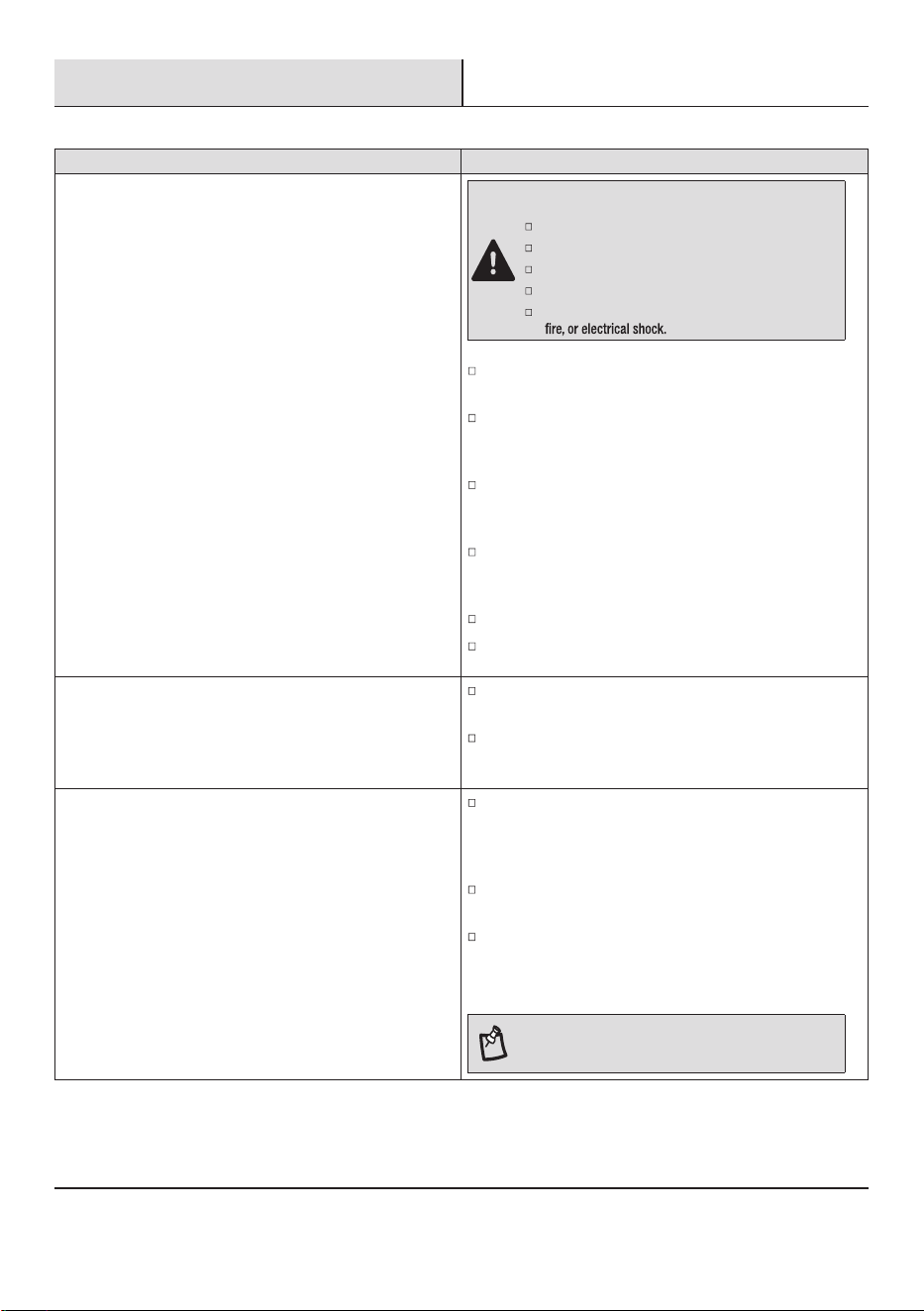
Air conditioner will not operate
DANGER: ELECTRICAL SHOCK HAZARD
Plug into a grounded 3-prong outlet.
Do not remove ground prong.
Do not use an adapter.
Do not use an extension cord.
Failure to follow these instructions can result in death,
Air conditioner blows fuses or trips circuit breakers
Too many appliances are being used on the same circuit. Unplug
or relocate appliances that share the same circuit.
You are trying to restart the air conditioner too soon after turn-
ing off air conditioner. Wait at least 3 minutes after turning off
air conditioner before trying to restart the air conditioner.
Air conditioner power supply cord trips (Reset button pops out)
Disturbances in your electrical current can trip (RESET button
will pop out) the power supply cord. Press and release RESET to
resume operation. (Listen for click; RESET button will latch and
remain in.)
Electrical overloading, overheating, cord pinching or aging can
trip (RESET button will pop out) the power supply cord.
After correcting the problem, press and release RESET to
resume operation. (Listen for click; RESET button will latch
and remain in.) If the power cord fails to rest, contact a service
technician.
NOTE: A damaged power supply cord must be replaced
with a new power supply cord obtained from the product
manufacturer and must not be repaired.
22
The power supply cord is unplugged. Plug into a grounded
3-prong outlet. See “Electrical Requirements” on page 8.
Time-delay fuse or circuit breaker of the wrong capacity isbeing
used. Replace with a time-delay fuse or circuit breaker of the
correct capacity. See “Electrical Requirements” on page 8.
The power supply cord has tripped (Reset button has popped
out). Press and release RESET to resume operation. (Listen for
click; RESET button will latch and remain in.)
A household fuse has blown, or a circuit breaker has tripped.
Replace the fuse, or rest the circuit breaker. See “Electrical
Requirements” on page 8.
The On/Off button has not been pressed. Press ON/OFF.
The local power has failed. Wait for power to be restored.
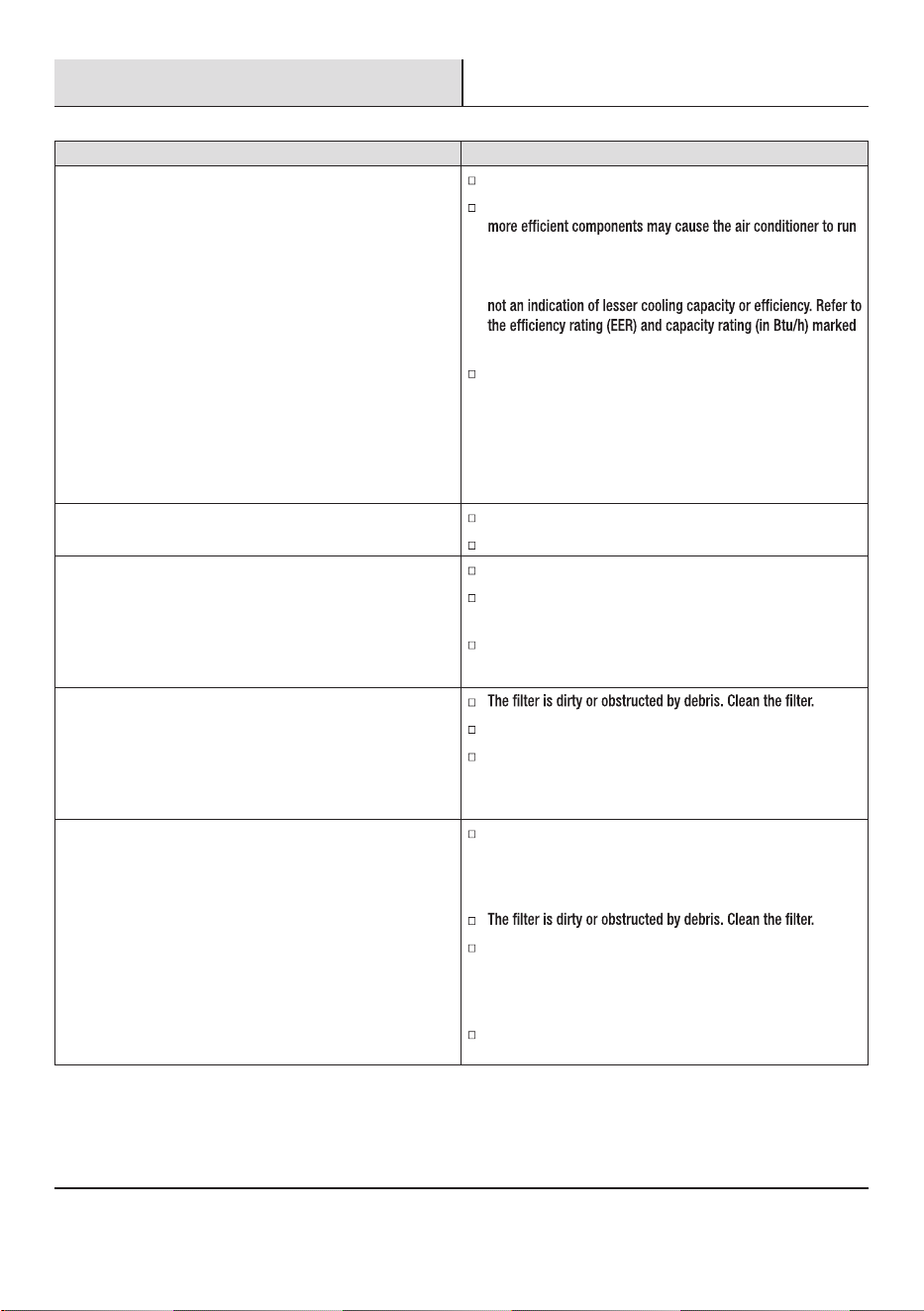
Troubleshooting (continued)
Problem Solution
Air Conditioner seems to run too much
A door or window is open. Keep doors and windows closed.
The current air conditioner replaced an older model. The use of
longer than an older model, but the total energy consumption
will be less. Newer air conditioners do not emit the “blast” of
cold air you may be accustomed to from older units, but this is
on the air conditioner.
The air conditioner is in a heavily occupied room, or heat
producing appliances are in use in the room. Use exhaust vent
fans while cooking or bathing and try not to use heat-producing
appliances during the hottest part of the day. Portable air
conditioners are designed as supplemental cooling to local
areas within a room. A higher capacity air conditioner may be
required, depending on the size of the room being cooled.
Air conditioner runs for a short time only, but room is not cool
Set temperature is close to room temperature.
Lower set temperature. See “Operation”.
Display error code
Air conditioner runs, but does not cool
Air outlet is blocked. Clear air outlet.
Set temperature is too high. Lower set temperature.
Air conditioner cycles on and off too much
The air conditioner is not properly sized for your room. Check
the cooling capabilities of your portable air conditioner. Portable
air conditioners are designed as supplemental cooling to local
areas within a room.
There is excessive heat or moisture, open container cooking,
showers, etc. in the room. Use a fan to exhaust heat or moisture
from the room. Try not to use heat-producing appliances during
the hottest part of the day.
The louvers are blocked. Install the air conditioner in a location
where the louvers are free from curtains, blinds, furniture, etc.
23
If the unit displays error code E5, the water container is full.
Drain the water, see “Draining the Air Conditioner” on page
20. After draining, the unit can be operated again.
If the unit displays error code E1/E2/E3/E4/E6/E7/EA, please
contact customer service.
4
8
33
37
43
45
A2L
A2L
MODE FAN
TIMER DIMMER
Sleep [ 5 sec ]
SWING
F / C
[ 5 sec ]
H
D
E
F
G
A
B
C
MODE FAN
TIMER DIMMER
Sleep [ 5 sec ]
SWING
F / C [ 5 sec ]
Fuente de alimentación
icca ed elbisuFoledoM ón retardada (o disyuntor)
115V
103.5V min.
126.5V max.
A01UTBK5
A31UTBK6
20 pulg.
(50 cm)
20 pulg.
(50 cm)
20 pulg.
(50 cm)
20 pulg.
(50 cm)
1
31
BB
CC
2
31
34
2a
Conecte la manguera al ventanal.
Conecte la manguera de escape al adaptador de salida de la ventana.
En primer lugar, instale sellos de espuma (MM) (tipo de
adhesivo más corto) en los lados izquierdo y derecho, y luego
coloque sellos de espuma (LL) (tipo de adhesivo más largo)
en los lados superior e inferior.
MM
LL
AA
HH
II, JJ or KK
GG
FF
35
2b
Conecte la manguera al ventanal.
Conecte la manguera de escape al adaptador de salida de la ventana.
En primer lugar, instale sellos de espuma (MM) (tipo de
adhesivo más corto) en los lados izquierdo y derecho, y luego
coloque sellos de espuma (LL) (tipo de adhesivo más largo)
en los lados superior e inferior.
Corte la junta de espuma (AA) (tipo no adhesivo) a la anchura
de la ventana.Rellene la junta de espuma (AA) entre el cristal
y la ventana para evitar la entrada de aire y objetos extraños
en la habitación.
FF
GG
HH
II, JJ or KK
AA
MM
LL
36
1
NOTA:
Retire la cinta antes de usar.
(válido para algunos modelos)
NOTE:
En caso de fallo de alimentación, el aire acondicionado funcionará con los ajustes previos cuando se restaure la alimentación.
No permanezca en el ujo de aire directo del aire acondicionado durante largos períodos de tiempo.
Nunca lo utilice en espacios cerrados. Asegúrese siempre de que haya un ujo de aire exterior adecuado en el hogar, especialmente
cuando se utilice con aparatos combustibles como estufas de gas, chimeneas, hornos, calentadores de agua, etc. No coloque el cable
de alimentación ni el aire acondicionado cerca de un calefactor, radiador, estufas u otros aparatos (incluidos amplicadores) que
produzcan calor.
Este aire acondicionado está destinado al uso doméstico como aparato residencial. No lo utilice como climatizador de precisión para
uso comercial, ni para equipos de precisión, alimentos, animales domésticos, plantas, obras de arte, etc.
No bloquee ni obstruya la manguera de ventilación de escape, ya que puede afectar gravemente al rendimiento o provocar fallos en el
aire acondicionado.
Si se cambia el modo con el aire acondicionado funcionando, el compresor no se reiniciará durante 3 a 5 minutos. Si se presiona algún
botón durante este tiempo, el aire acondicionado no se reiniciará durante otros 3 a 5 minutos.
En modo de Refrigeración o Secado, el compresor y el ventilador del condensador se detendrán cuando la temperatura ambiente
alcance la temperatura ajustada.
En el modo Secado, el nivel de humedad se ajusta automáticamente, pero no se puede mostrar.
37
Presione FAN para seleccionar Alta o Baja.
son Cool, Dry or Fan.
Rango de temperatura ambiente para el funcionamiento del aparato:
Tape
Heat(Modo de
calentamiento de bomba)
Heat(Modo térmico eléctrico) ≤ 86°F(30°C)
Aire acondicionado de manguera única
MODO
Rango de temperatura ambiente
Cool 61-95°F (16-35°C)
41-86°F (5-30°C)
NOTE: En el caso de un corte de energía, su
aire acondicionado funcionará en los ajustes
anteriores cuando se restaura la energía.
2
CONTINUOUS: presione el ventilador y mantenga presionado durante 3 segundos para cambiar
al modo de ventilador continuo. En este modo, el ventilador de interior seguirá funcionando incluso cuando se
alcance la temperatura establecida. Para volver al modo anterior, presione y mantenga presiondurante 3
segundos de nuevo; El ventilador de interior se detendrá una vez que se alcance la temperatura establecida.
2
39
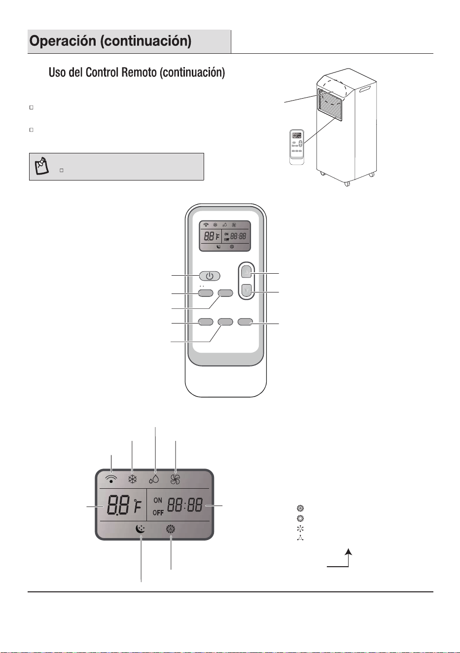
CÓMO UTILIZARLO
Para operar el aire acondicionado, dirija el control remoto a la
señal del receptor (1).
El control remoto hará funcionar el aire acondicionado a una
distancia de hasta 23 pies. (7m) cuando apunte al receptor de
señal del aire acondicionado.
FUNCIONES DE LOS BOTONES
SÍMBOLOS DE INDICACIÓN
1
MODE FAN
TIMER DIMMER
Sleep [ 5 sec ]
SWING
F / C
[ 5 sec ]
MODE FAN
SWING TIMER DIMMER
Sleep [ 5 sec ]
F / C [ 5 sec ]
Modo
Ventilador
Oscilación
Arriba
Abajo
Atenuador/Suspensión
Temporizador
Encendido/Apagado
Temporizador
Indicador de la velocidad del ventilador
Indicador de refrigeración
Indicador de secado
Indicador de modo Ventilador Solo
Muestra la
temperatura
ajustada
Indicador de suspensión
Transmisión de señal
Muestra la velocidad del ventilador seleccionada:
Velocidad de ventilador media
Velocidad de ventilador baja
Velocidad de ventilador automática
Velocidad de ventilador alta
NOTE:
El control remoto puede tener un aspecto diferente.
40
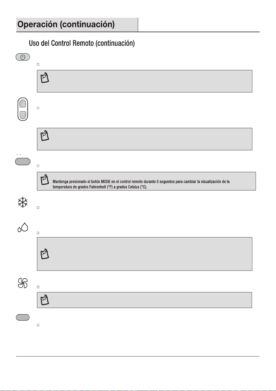
ENCENDIDO O APAGADO
NOTA:
Al cambiar los modos durante el funcionamiento, la unidad puede no responder inmediatamente. Por favor, tenga paciencia,
ya que el compresnecesita 3 minutos para reiniciar después de apagar.
Pulse el botón de encendido/apagado para encender o apagar la unidad.
NOTA: La velocidad automática del ventilador no se puede seleccionar en el modo sólo ventilador.
INDICADOR DE SECADO
El aire acondicionado selecciona automáticamente la temperatura. El ventilador funciona sólo a baja velocidad.
INDICADOR DE MODO VENTILADOR SOLO
Sólo el ventilador funciona. Pulse el botón ventilador para ajustar la velocidad del ventilador.
INDICADOR DE REFRIGERACIÓN
Enfriar la habitación. Pulse ventilador para seleccionar AUTO, alto, medio o bajo.
Presione el botón arriba o abajo para ajustar la temperatura.
NOTA:
No debe usarse el modo seco para enfriar la habitación.
Una disminución o aumento de hasta 7 °C se puede ajustar con el mando A distancia si todavía te sientes incómodo.
Algunos modelos pueden disminuir o subir hasta 2 °C.
Consulte el panel de control del aire acondicionado para la temperatura exacta.
NOTA:
En el modo de enfriamiento y calentamiento, la temperatura se puede ajustar entre 61°F y 86°F (16°C y 30°C).
En el modo solo ventilador, la temperatura no se puede ajustar.
MODO
ARRIBA ABAJO
Presione el botón arriba o abajo para ajustar la temperatura.
Pulse el botón arriba una vez para aumentar la temperatura de 1 °F (1 °C).
Pulse el botón de abajo una vez para disminuir la temperatura establecida en 1 °F (1 °C).
Presione MODE para seleccionar COOL, DRY o FAN.
NOTA:
MODE
F / C [ 5 sec ]
VELOCIDAD DEL VENTILADOR
Presione y suelte el ventilador para elegir la velocidad deseada.
FAN
2
41
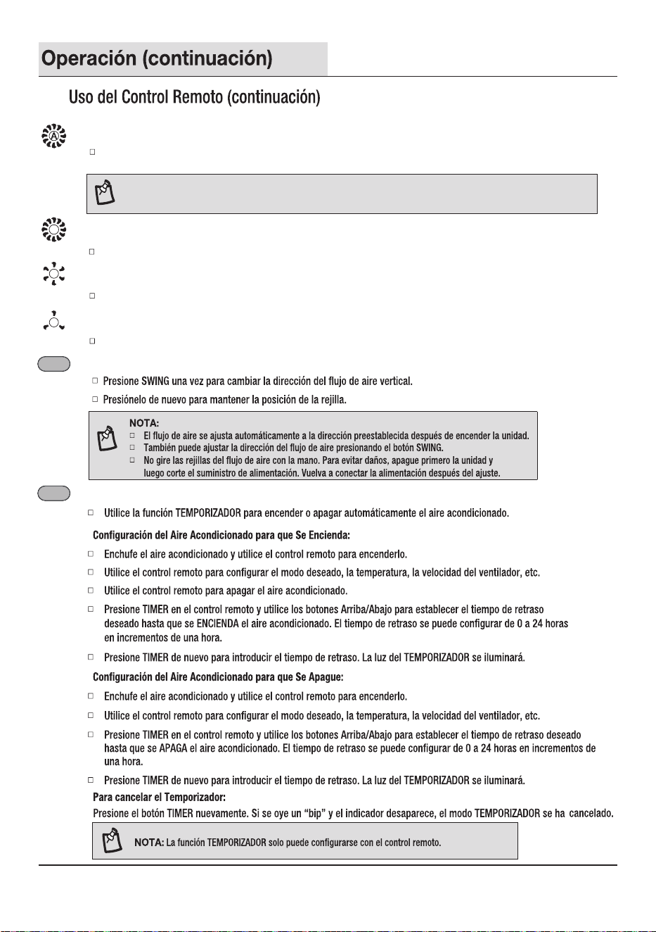
VELOCIDAD DE VENTILADOR AUTOMÁTICA
NOTA:
La velocidad automática del ventilador no se puede seleccionar en el modo sólo ventilador.
Automáticamente controla la velocidad del ventilador dependiendo de la temperatura ambiente actual
y la temperatura de ajust e.
VELOCIDAD DE VENTILADOR ALTA
Alta para una máxima velocidad del ventilador.
VELOCIDAD DE VENTILADOR MEDIA
VELOCIDAD DE VENTILADOR BAJA
Baja para una velocidad mínima del ventilador.
Mid para la velocidad normal del ventilador.
2
OSCILACIÓN (No se aplica a este modelo)
SWING
TEMPORIZADOR
TIMER
2
DIMMER
Sleep [ 5 sec ]
DIMMER
Sleep [ 5 sec ]
42
NOTA:
NOTA:
3
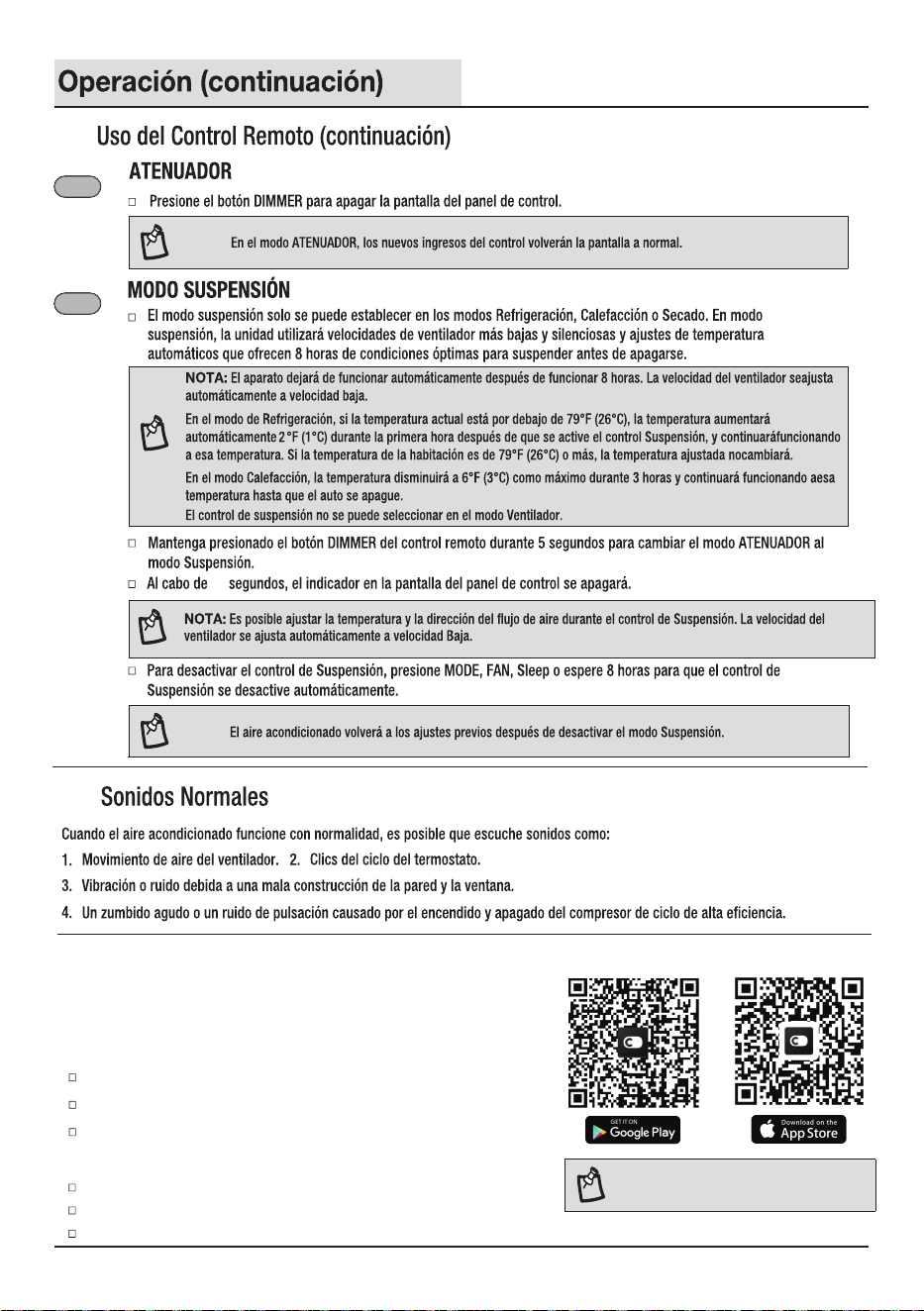
Escanee para descargar la aplicación ConnectLife.
También puedes ir a Google Play o App Store y buscar la aplicación ConnectLife.
Siga las instrucciones de la APLICACIÓN para emparejar su electrodoméstico.
4
Usando la APLICACIÓN ConnectLife
La aplicación Connectlife de Hisense le brinda la posibilidad de monitorear
cómodamente la unidad y cambiar su conguración desde cualquierlugar.
DISPOSITIVOS REQUERIDOS PARA UTILIZAR EL SMART AC:
Teléfono inteligente con sistema iOS o Android compatible.
Router inalámbrico (se requiere una red de 2,4 GHz para conectarse).
Aire acondicionado inteligente.
DESCARGUE E INSTALE LA APLICACIÓN CONNECTLIFE
NOTA: sólo disponible en los modelos wi.
10
1a
2
2
1
43
3
4
Deje que el ltro se seque completamente al aire antes
devolver a colocarlo para garantizar la máxima ecacia.
Filtro de aire
Retire el ltro de aire.
44
30
30
0
45
43
46

4351529-01