
Technical Support and E-Warranty Certificate
www.vevor.com/support
PV COMBINER BOX
Model: SP-HL-S252310-15A
SP-HL-S252810-10A
SP-HL-S252810-15A
We continue to be committed to provide you tools with competitive price.
"Save Half", "Half Price" or any other similar expressions used by us only represents an
estimate of savings you might benefit from buying certain tools with us compared to the major
top brands and does not necessarily mean to cover all categories of tools offered by us. You
are kindly reminded to verify carefully when you are placing an order with us if you are
actually saving half in comparison with the top major brands.

- 1 -
Model:SP-HL-S252310-15A /SP-HL-S252810-10A /SP-HL-S252810-15A
Have product questions? Need technical support? Please feel free to
contact us:
Technical Support and E-Warranty Certificate
www.vevor.com/support
NEED HELP? CONTACT US!
This is the original instruction, please read all manual instructions
carefully before operating. VEVOR reserves a clear interpretation of our
user manual. The appearance of the product shall be subject to the
product you received. Please forgive us that we won't inform you again if
there are any technology or software updates on our product.
PV COMBINER BOX
- 2 -
Warning-To reduce the risk of injury, user must read
instructions manual carefully.
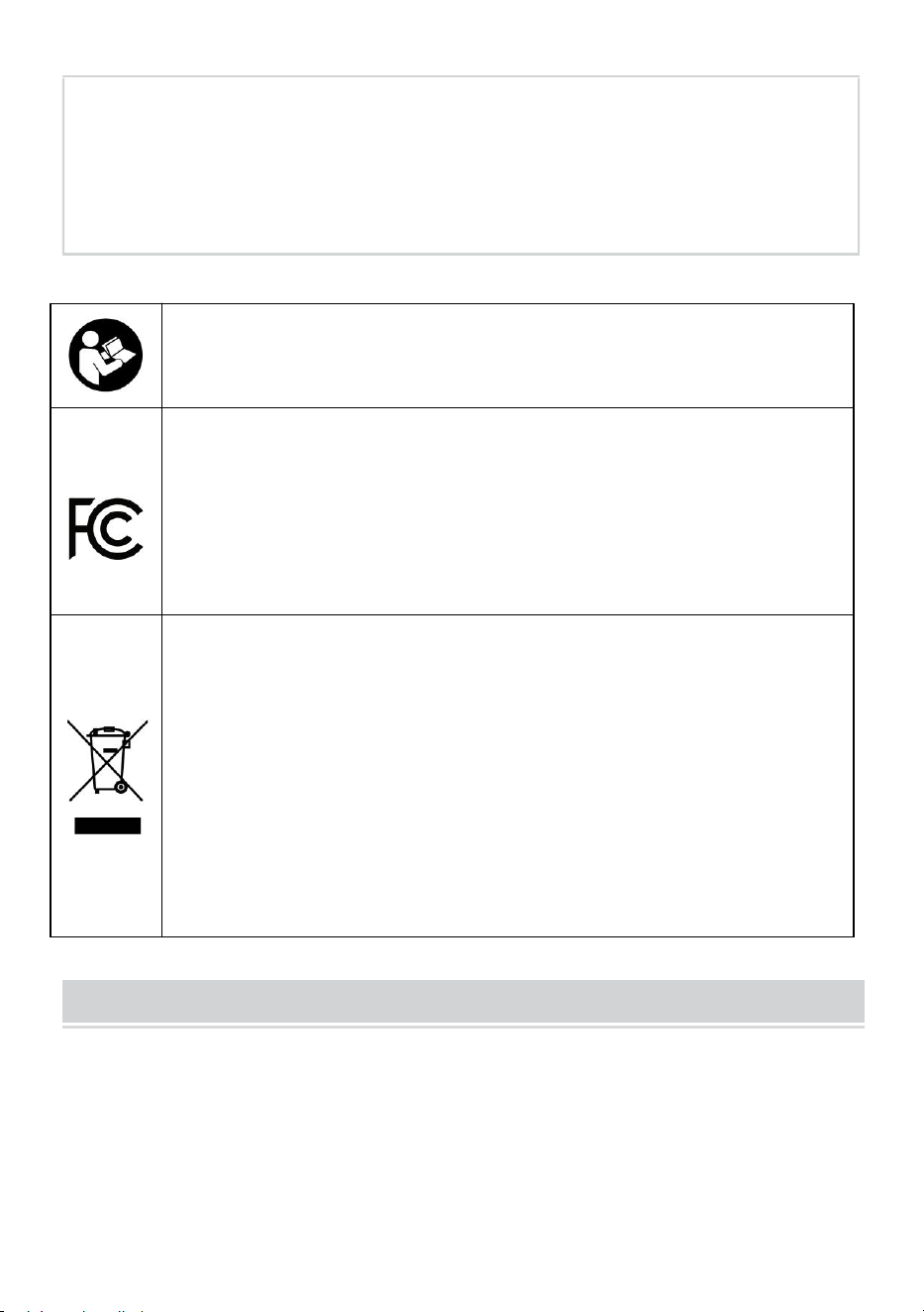
This device complies with Part 15 of the FCC Rules. Operation
is subject to the following two conditions:(1)This device may
not cause harmful interference, and (2)this device must accept
any interference received, including interference that may
cause undesired operation.
This product is subject to the provision of European Directive
2012/19/EC. The symbol showing a wheelie bin crossed
through indicates that the product requires separate refuse
collection in the European Union. This applies to the product
and all accessories marked with this symbol. Products marked
as such may not be discarded with normal domestic waste, but
must be taken to a collection point for recycling electrical and
electronic devices
Identification and Description
In order to better use product,please read the following instructions symbol:
WARNING!
This symbol identification for informal operation might
be in the safety of users dangerous or may cause
significant hardware damage.
Installation before use, please read this manual.
WARNING!
All the operation and line connection ask professional
personage to operation.
- 3 -
WARNING!
Please pay attention to personal and equipment safety.
WARNING!
Please note that photovoltaic array input of positive
and negative polarity and the total output of the positive
and negative polarity.
WARNING!
Installation or connection pv modules,please note pv
modules high voltage,avoid produce shock hazard.
WARNING!
Ensure that the connection of fastening,for the user to
use improper or cable wiring the loss caused by
unstable, vevor company does not undertake any
responsibility.
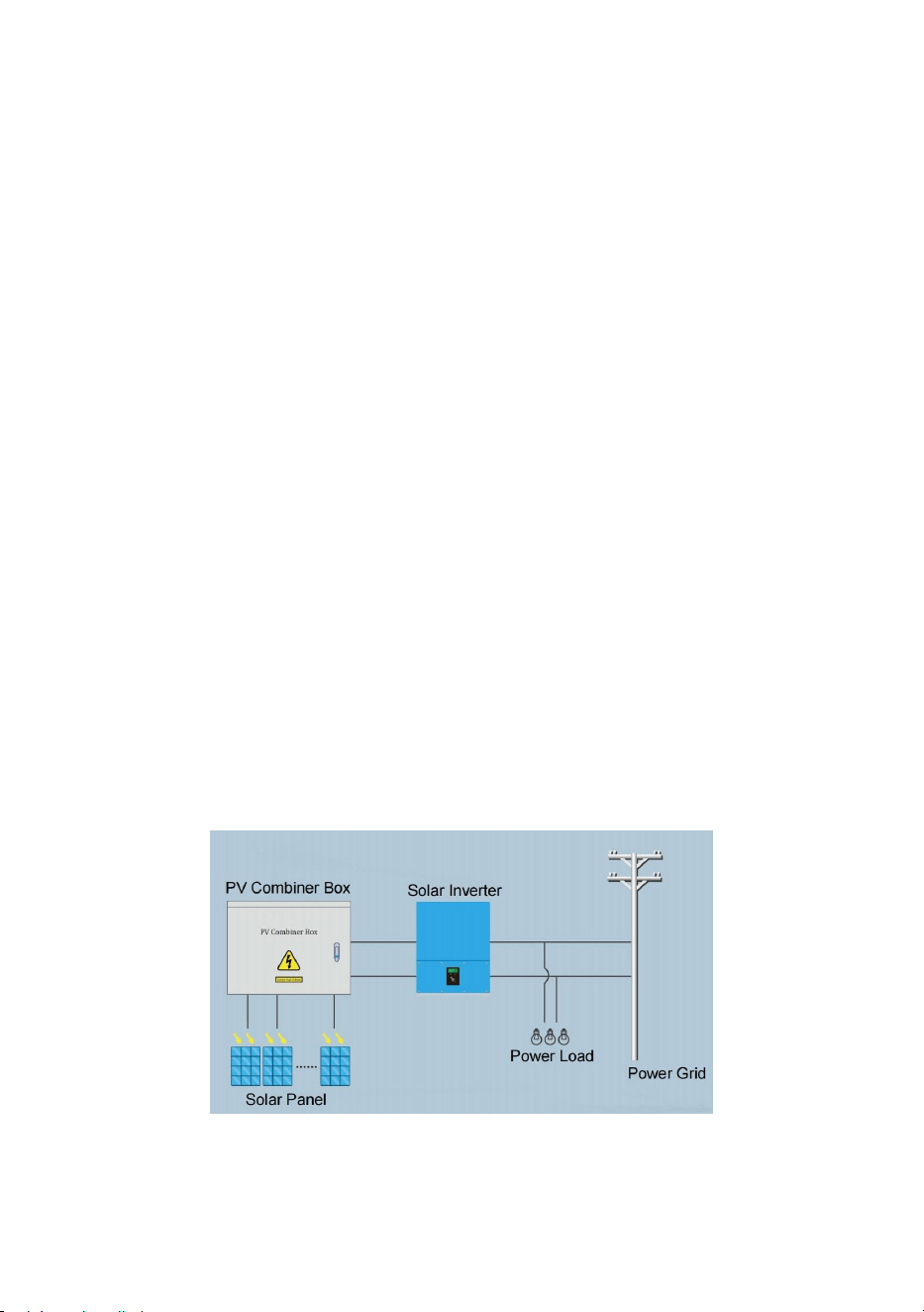
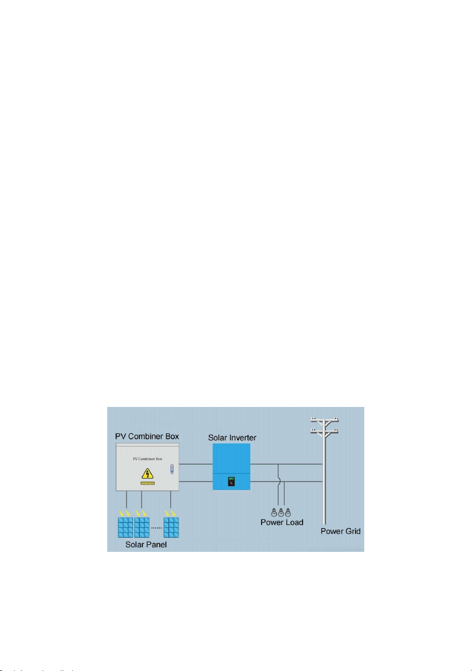
Product Introduction
Photovoltaic power generation system,in order to reduce the photovoltaic
module and inverter between the connecting cables,convenient
maintenance, reduce the loss and improve the safety and reliability of the
product, generally require in the photovoltaic module and inverter added
between confluence device.
Photovoltaic junction box besides having the function of pv bus outside,
and at the same time, should also have a current counter-attack, over
current protection, over-voltage protection, lightning protection and a series
of perfect protection function.
This company produces the photovoltaic junction box with the above
various functional requirements, and photovoltaic (PV) grid, from network
type inverter supporting the use can form a complete set of photovoltaic
power generation system solutions.
- 4 -
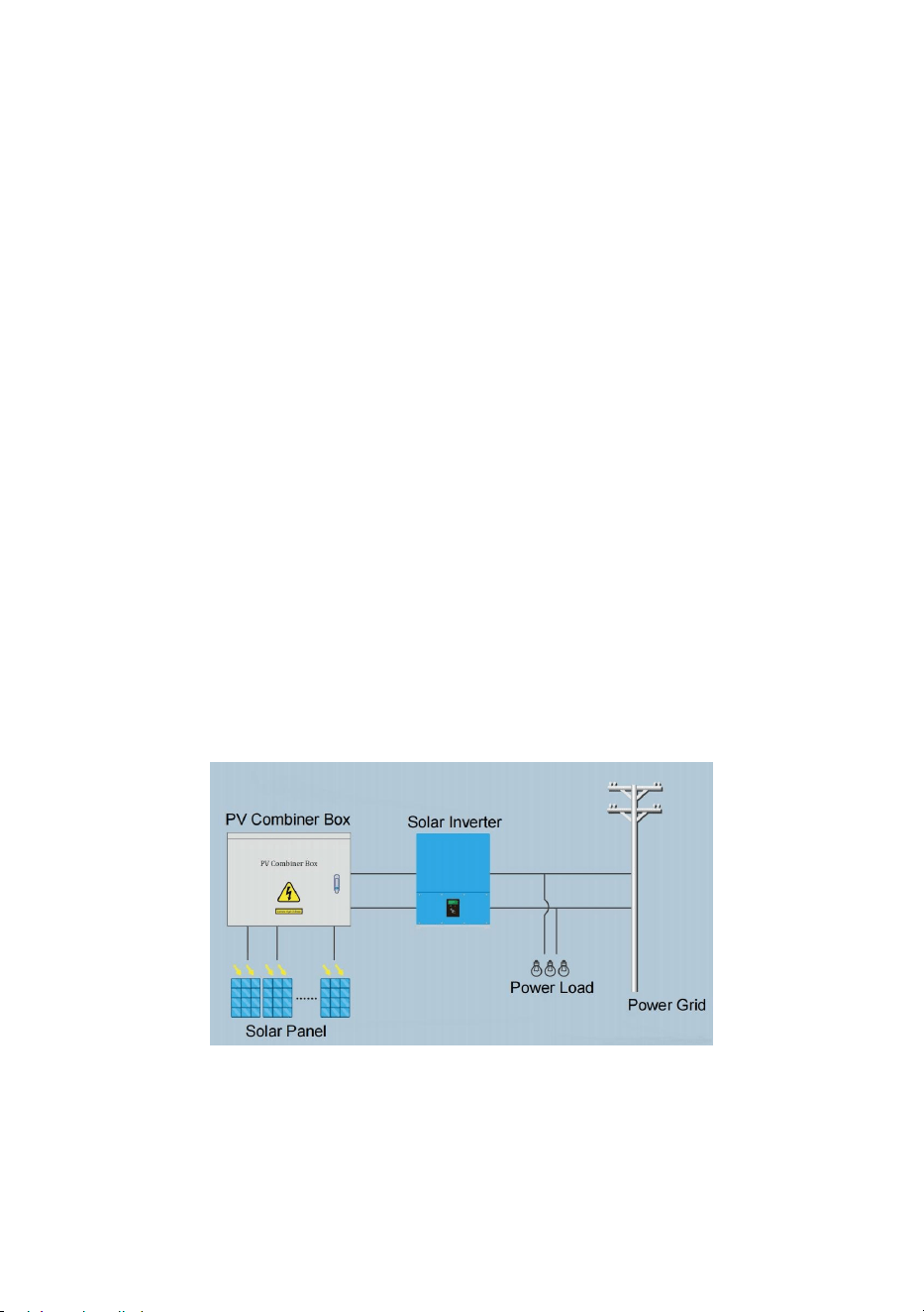
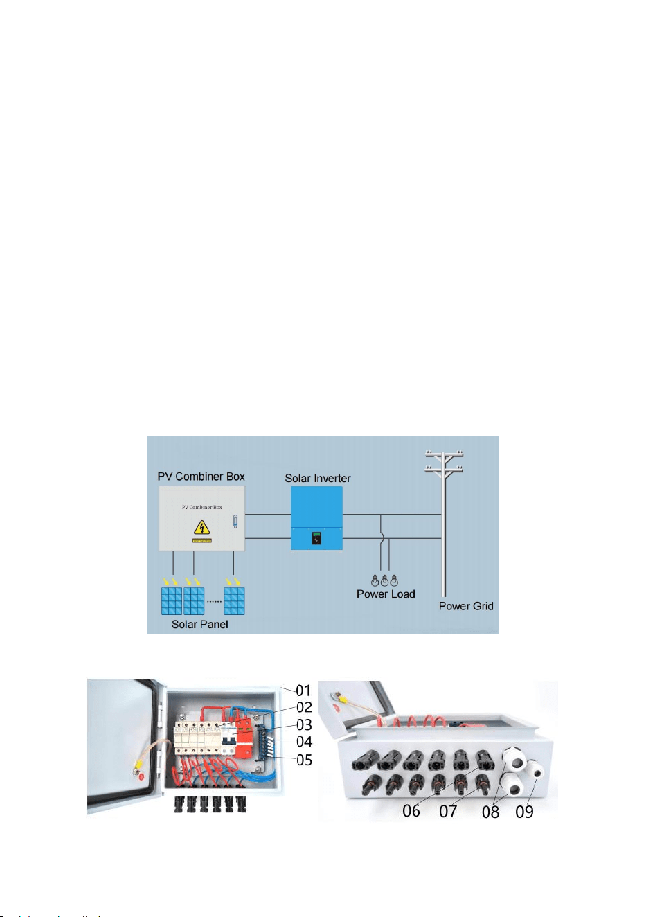
Select photovoltaic junction box, the user can according to the back end
inverter input voltage range, output power size, a certain number of
specifications of the same pv module series, parallel composition pv
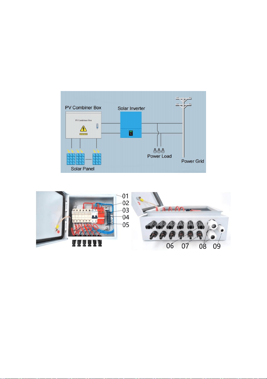
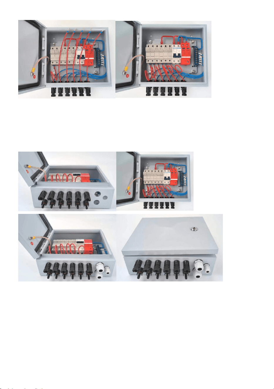
module series coordinate access photovoltaic junction box (see Figure1)
bus, and then after circuit breaker control and lightning protection device
protection after output for level inverter use.
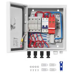
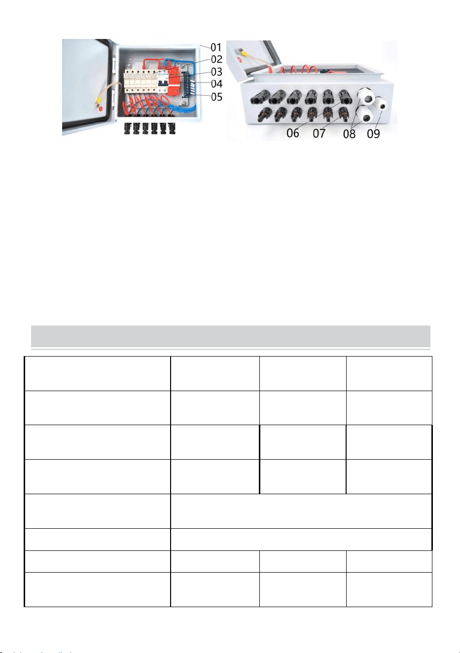
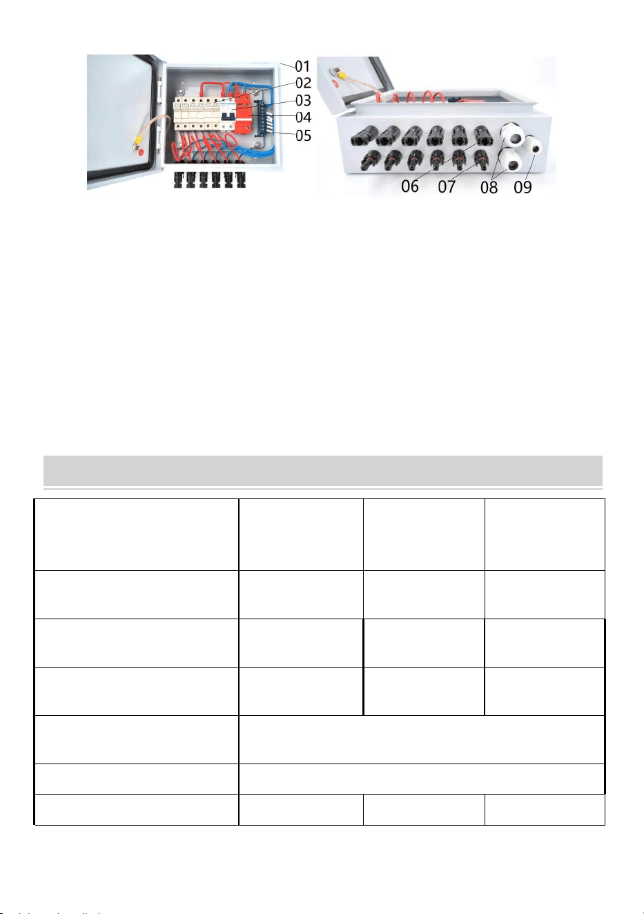
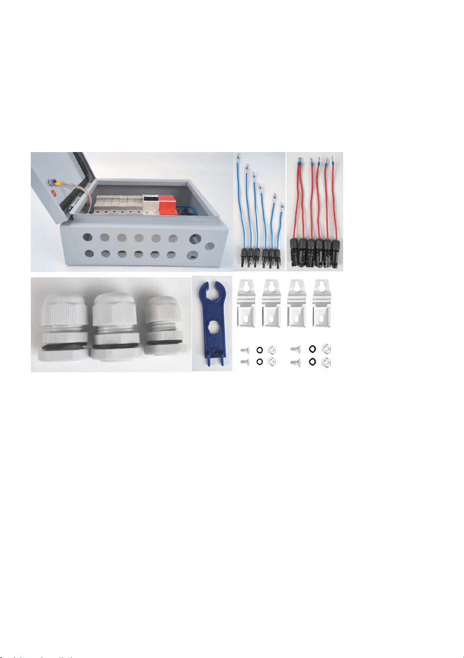
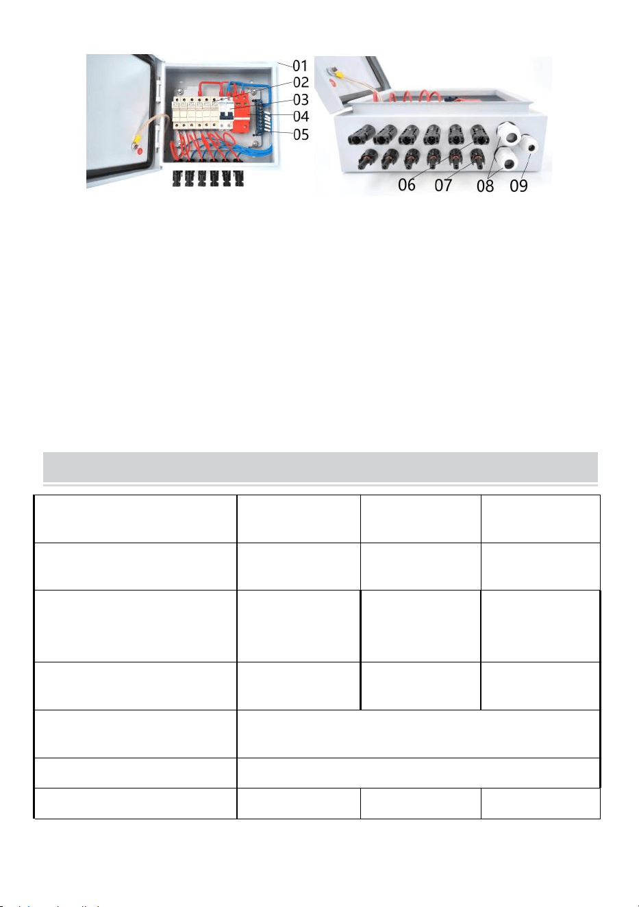
Figure 2 showed related parts and its specification.
Figure 1
Figure 2
01---Waterproof Metal Box
02---4pcs/6pcs DC500V Fuse holder with 10/15A fuse
03---63A/125A 2P DC500V MCB
04---SU6-40KA 2P DC500V SPD
05---Neutral Bar
06---4pcs/6pcs Solar Female Connector
07---4pcs/6pcs Solar Male Connector
08---2pcs Output PG16 Cable Gland
09---Earthing PG9 Cable Gland
- 5 -
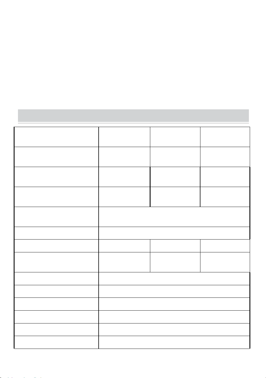
Production Specification
Model
SP-HL-S252310
-15A
SP-HL-S252810
-10A
SP-HL-S252810
-15A
PV array input numbers
4
6
6
Max single PV array current
15A
10A
15A
Single PV array fuse
15A
10A
15A
Single PV array wire size
2.5mm
2
Output numbers
1
Max output current
60A
60A
90A
Output wire size
10mm
2
10mm
2
16mm
2
Max output voltage
500VDC
DC output circuit breaker
yes
Protection level
IP66
Temperature range
-30℃ ~ +60℃
Cooling way
Natural cooling
SPD protection
yes
Ground wire size
≥2.5mm²
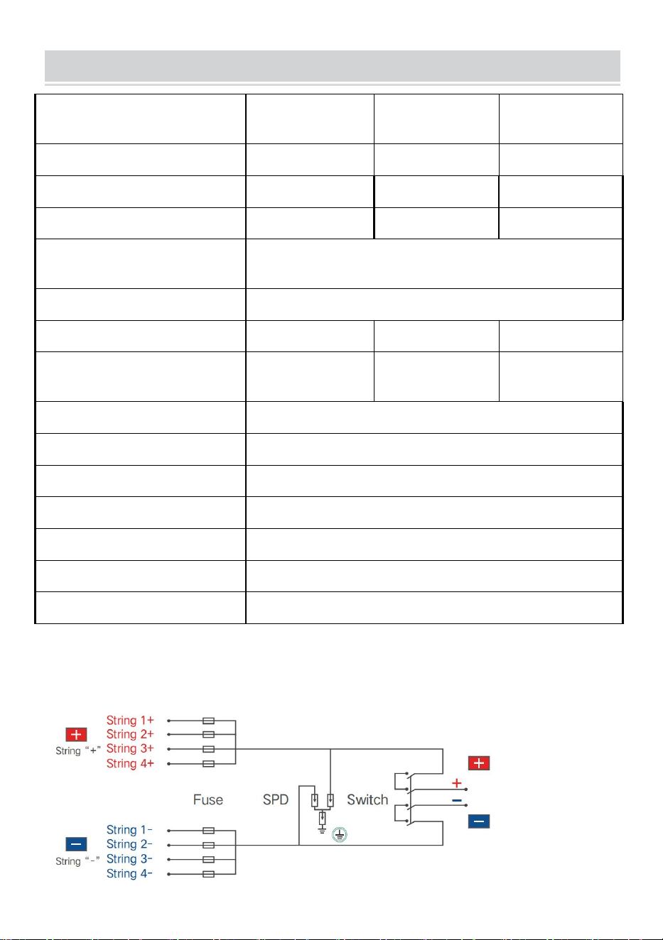
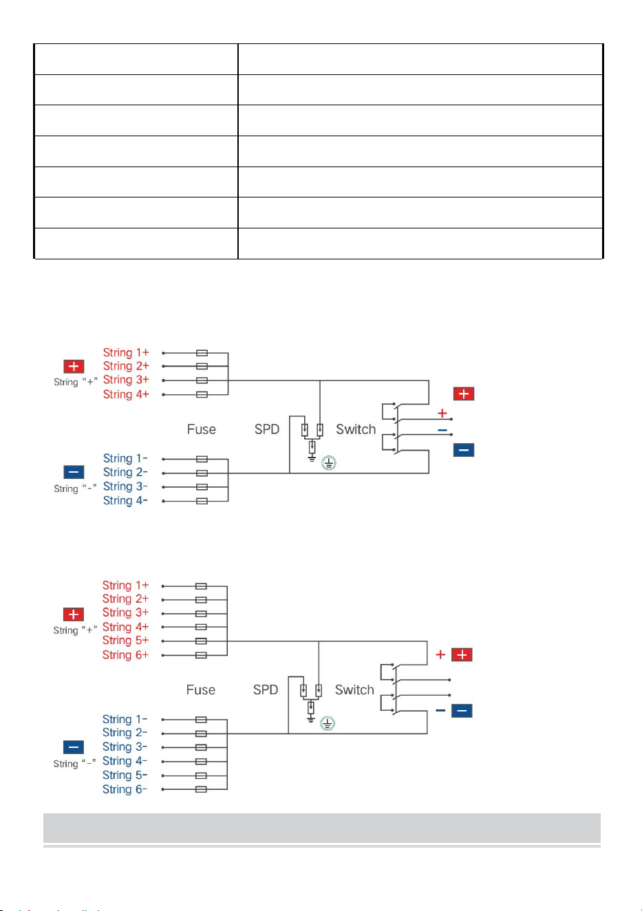
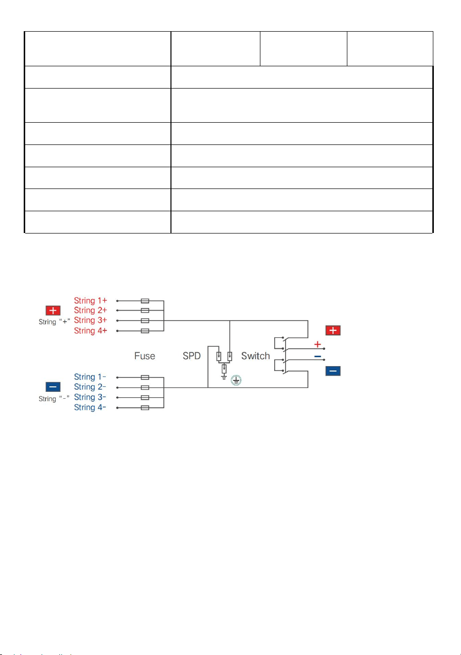
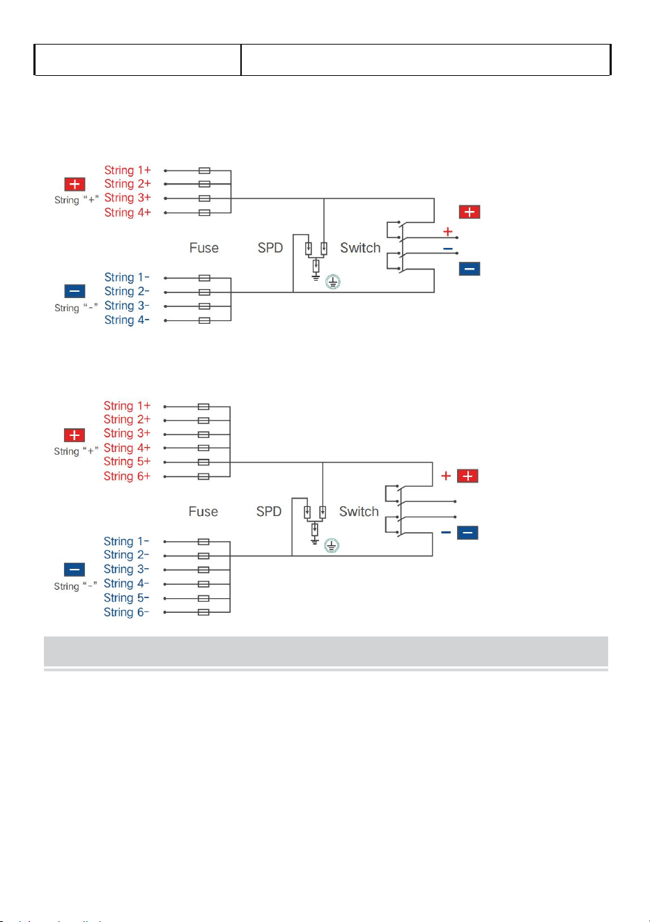
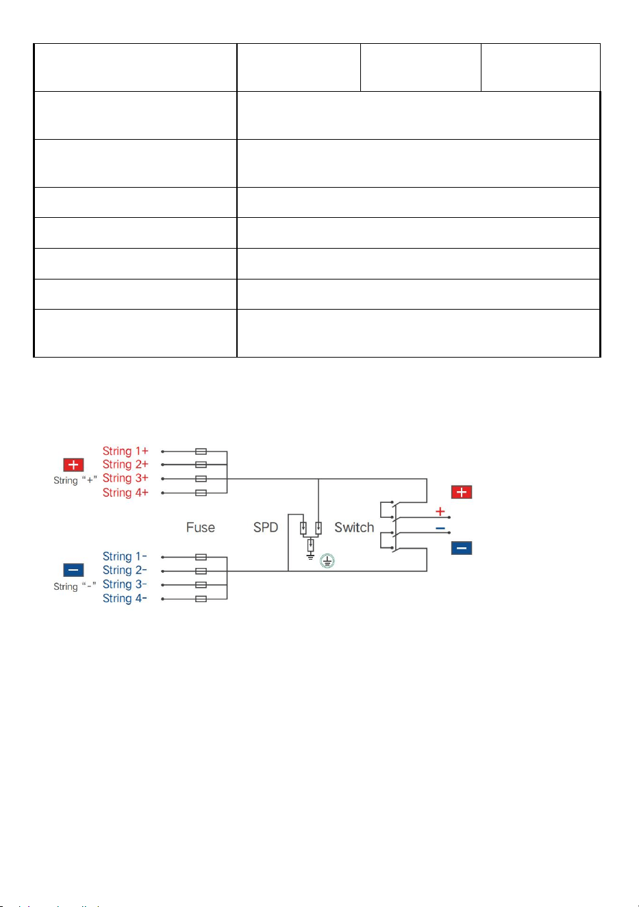
SP-HL-S252310-15A 4 input 1 output PV combiner box wiring diagram as
follows:

- 6 -
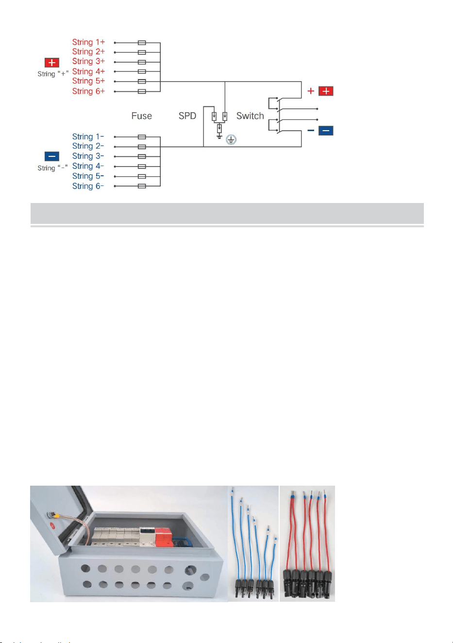
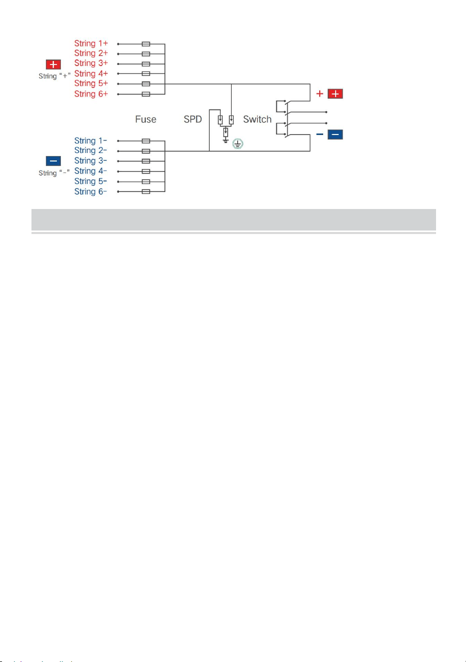
SP-HL-S252810-10A and SP-HL-S252810-15A 6 input 1 output PV
combiner box wiring diagram as follows:
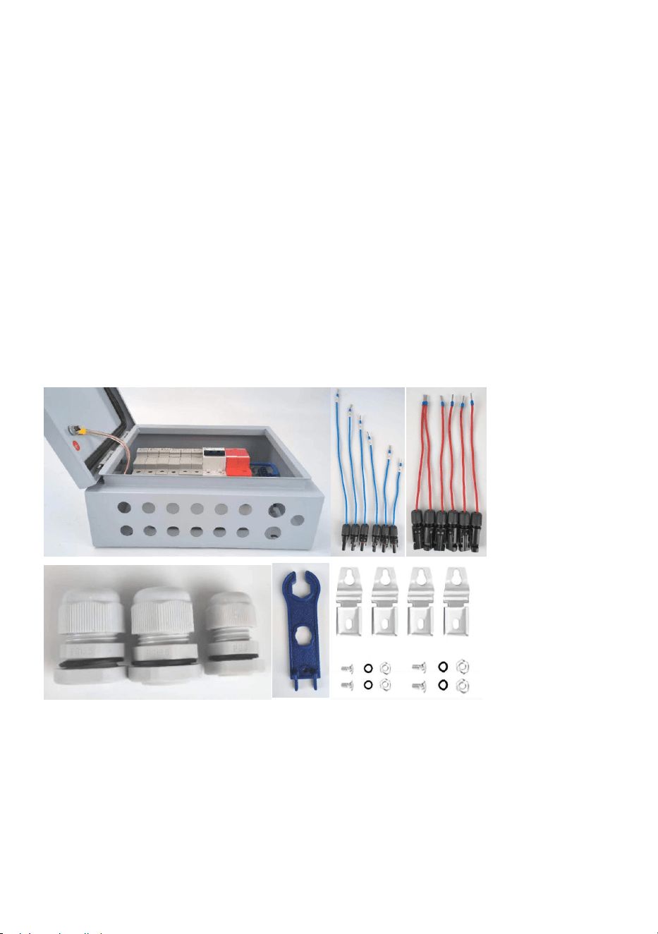
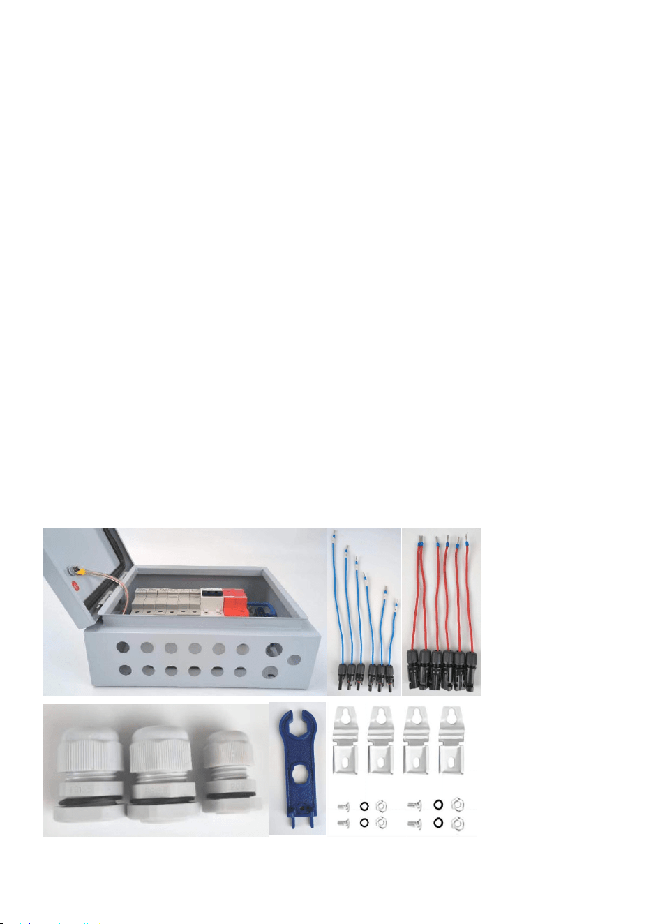
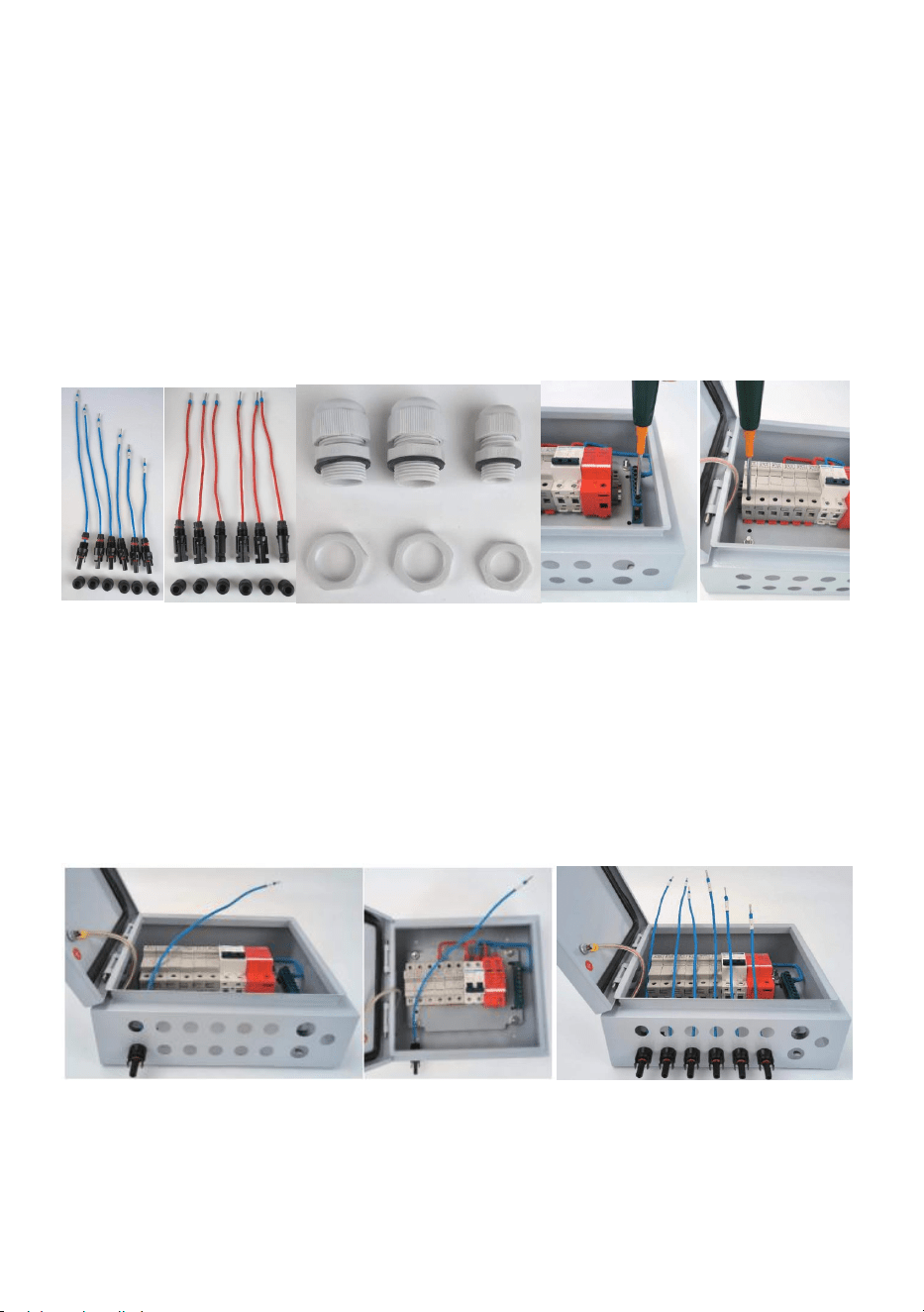
PV Combiner Box Assembly Process
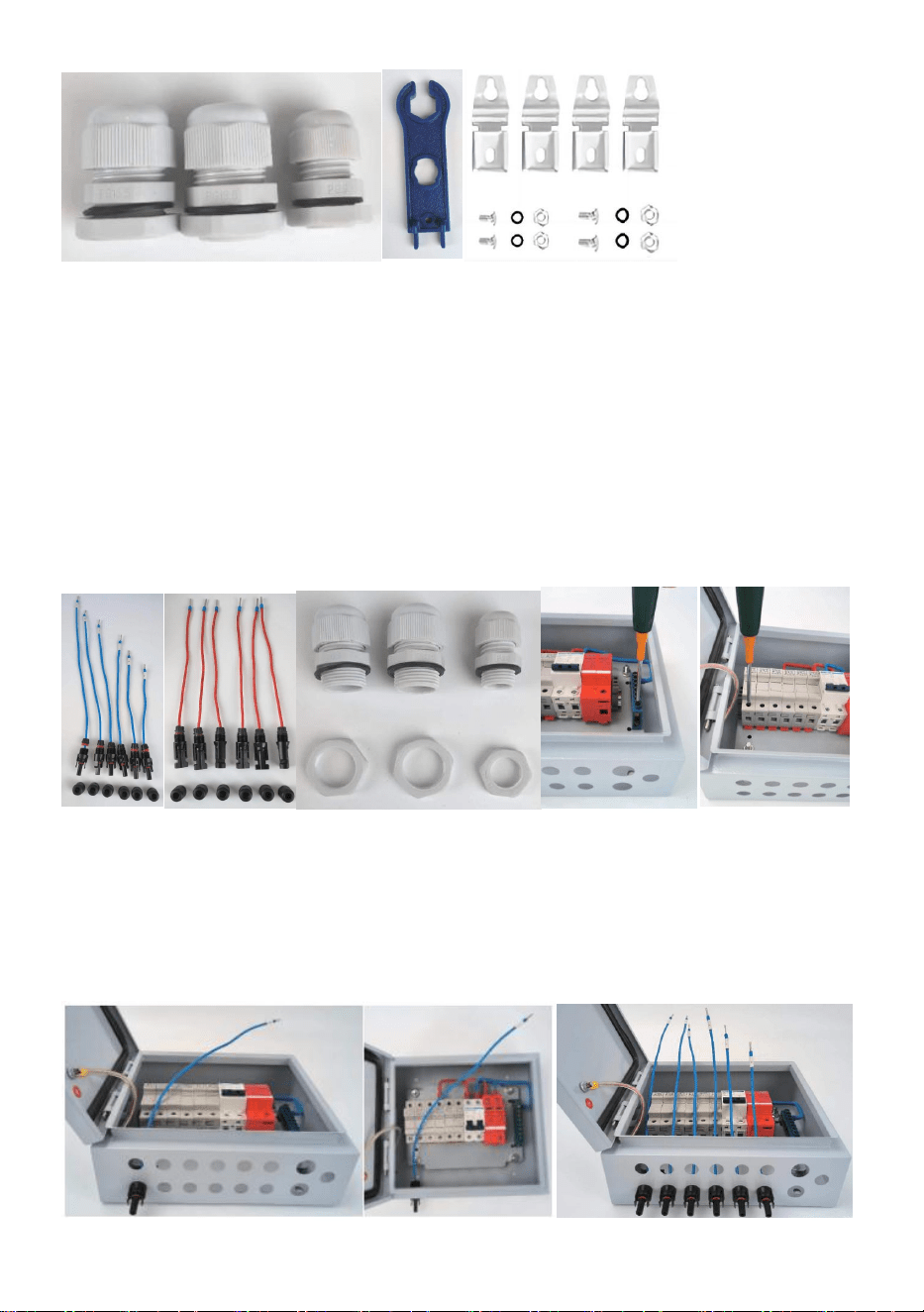
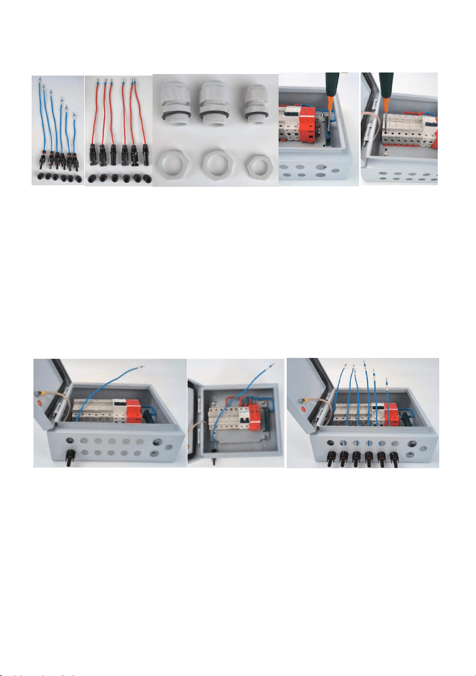
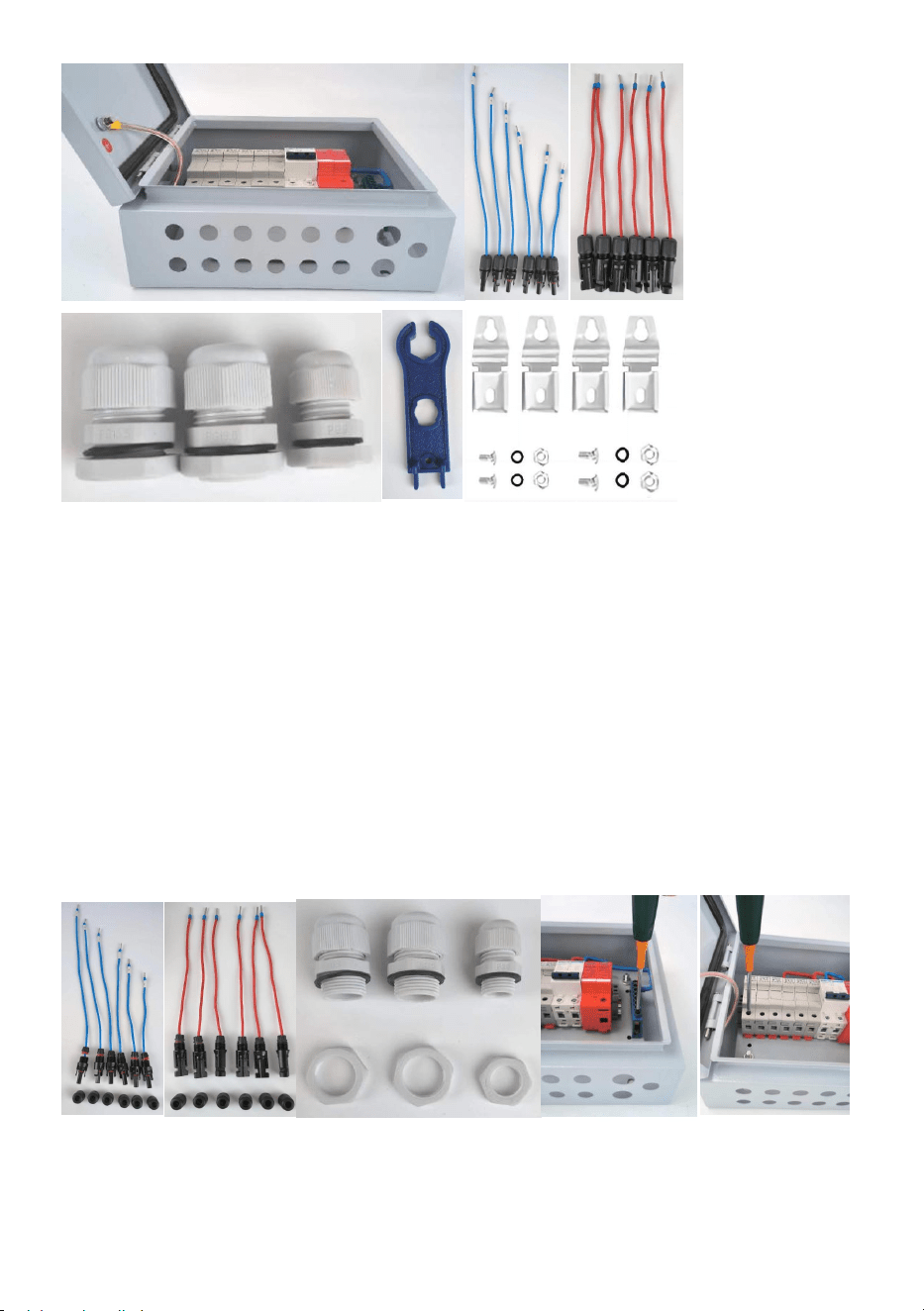
1. Accessories list:
(1) half-finished PV combiner box---1pcs;
(2) Input- MC4 male connector with cable----4pcs(for 4ways PV combiner
box)/6pcs(for 6ways PV combiner box);Tips:each cable is different
length,there have number label on each cable,notice to distinguish.
(3) Input+ MC4 female connector with cable----4pcs(for 4ways PV
combiner box)/6pcs(for 6ways PV combiner box);Tips:each cable keep
same length.
(4) Output+ PG13.5 cable gland--1pcs;
(5) Output- PG13.5 cable gland--1pcs;
(6) Earthing PG9 cable gland--1pcs;
(7) MC4 tool---1pcs;
(8) Wall mounting brackets bag---1set;
- 7 -
2. Preparatory work
(1) Loose Input- MC4 female connector’s mounting nut;
(2) Loose Input+ MC4 female connector’s mounting nut;
(3) Loose 3pcs cable glands’ mounting nut;
(4) Loose terminal block’s input terminals,make sure the following wiring
process easy to fix;
(5) Loose fuse holders’ input fix screws,make sure the following wiring
process easy to fix;
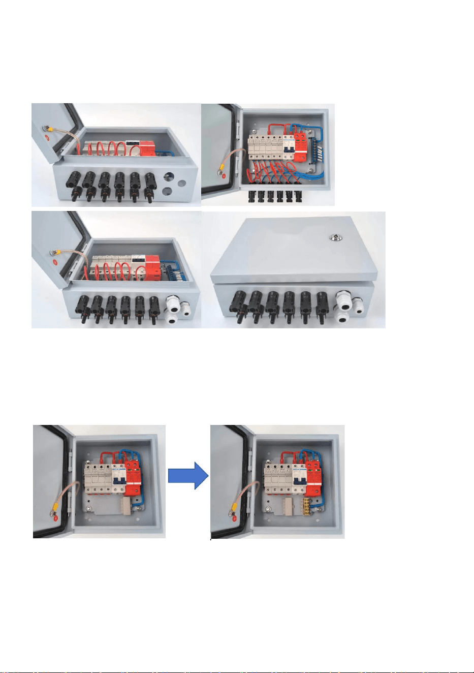
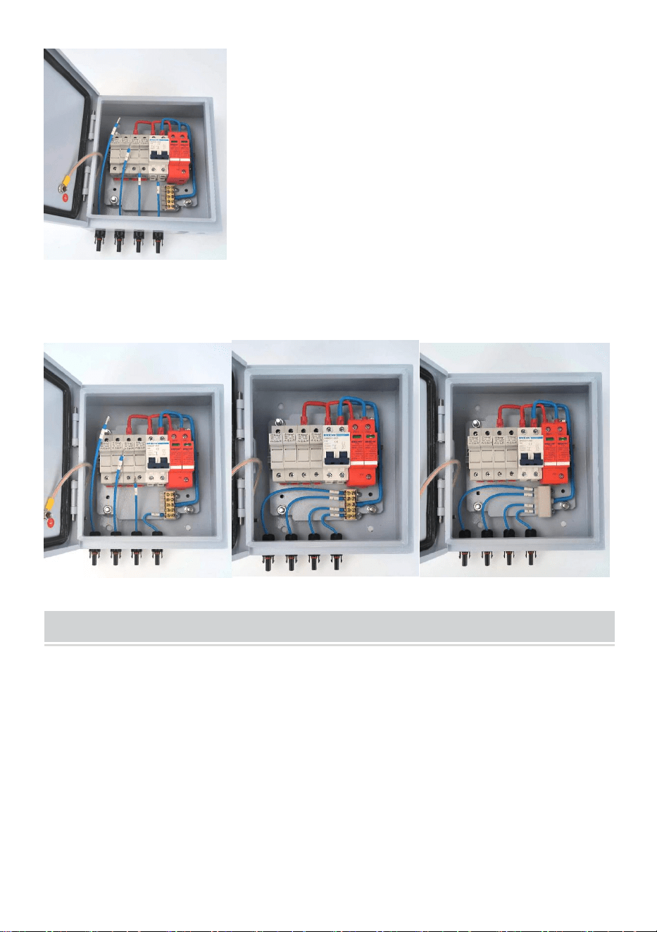
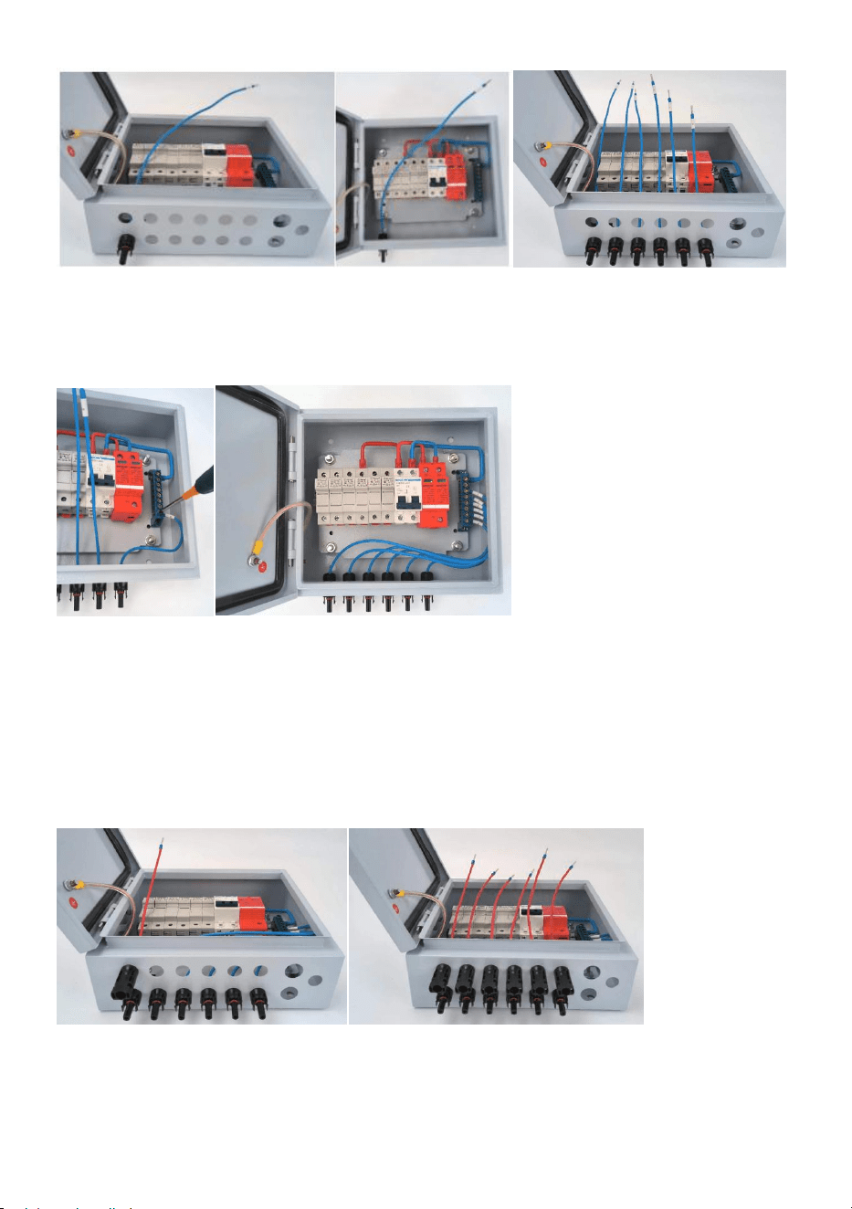
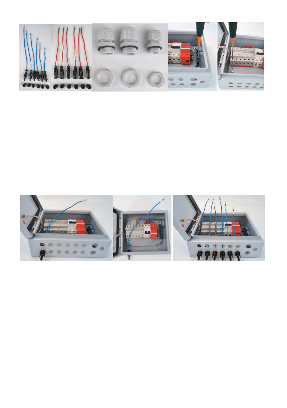
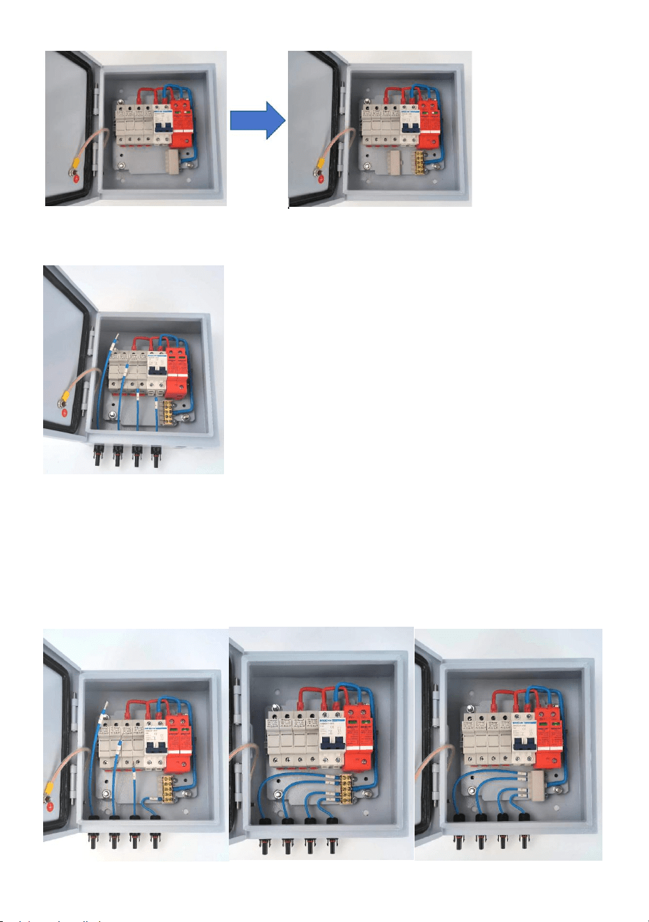
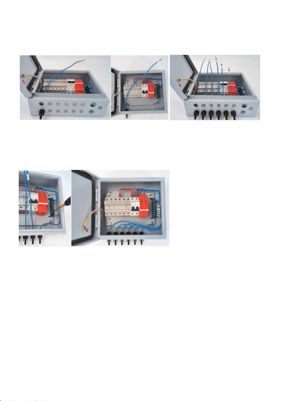
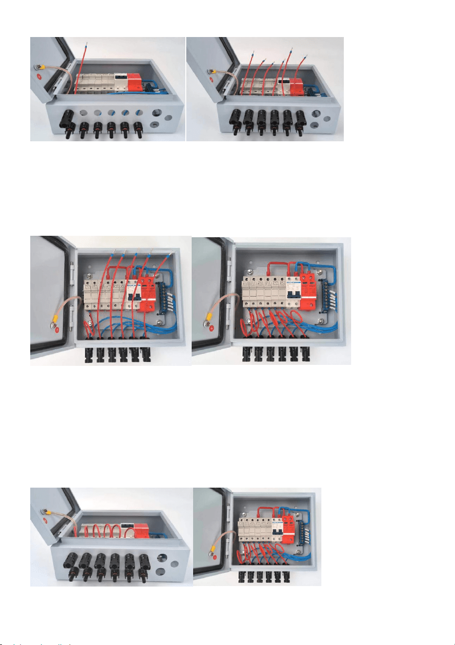
3. Wiring Input- MC4 male connector with cable
(1) Mounting No.1 cable on the picture 8 showed position,fix with nut;
(2) Mounting the rest of cables on the picture 9 showed position,fix with
nut.the cable number from left to right shall is No.1-No.6;
- 8 -
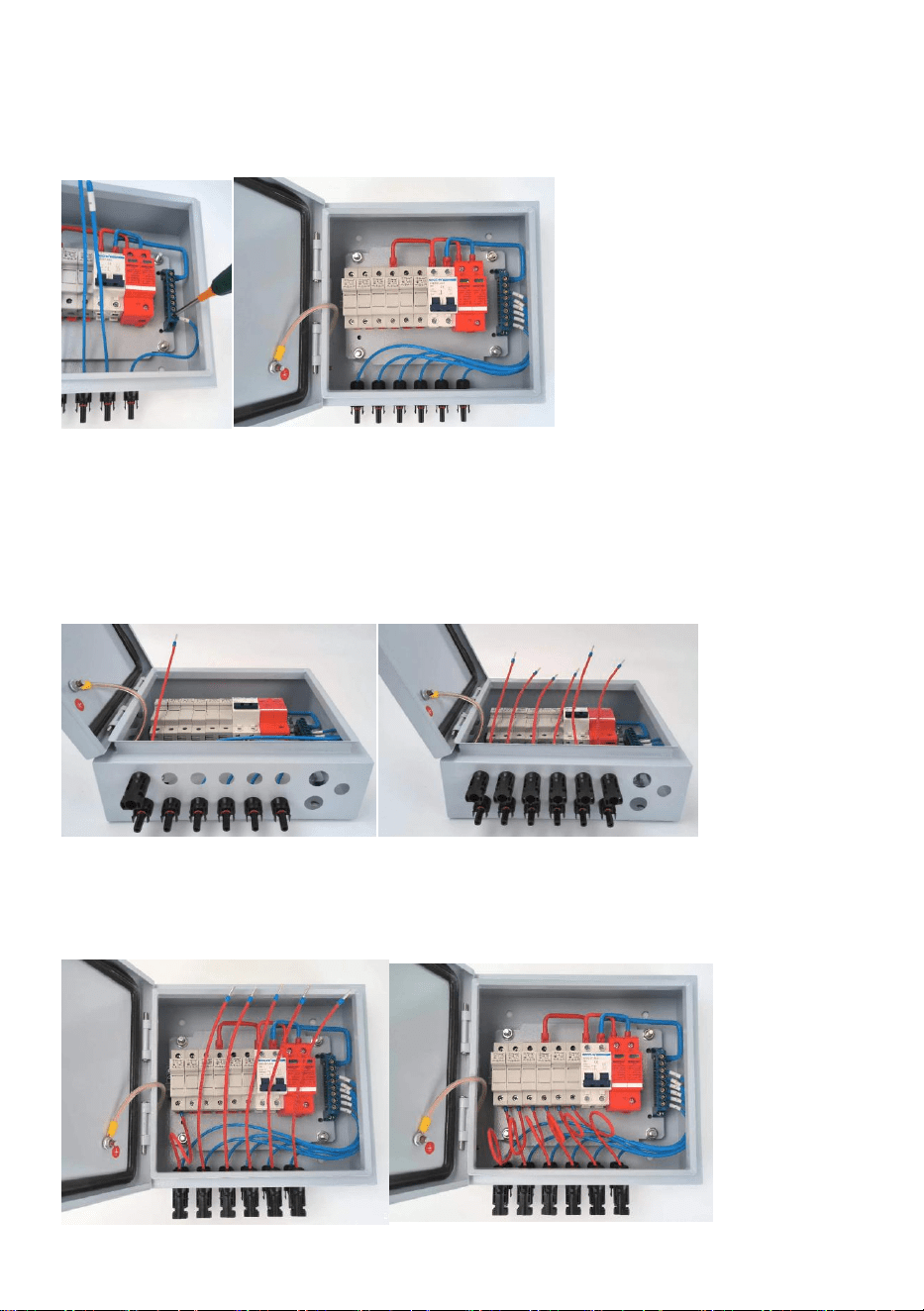
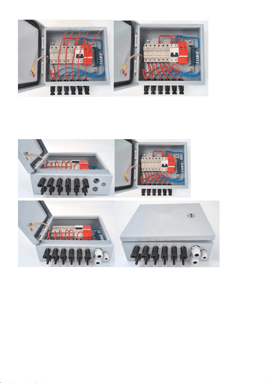
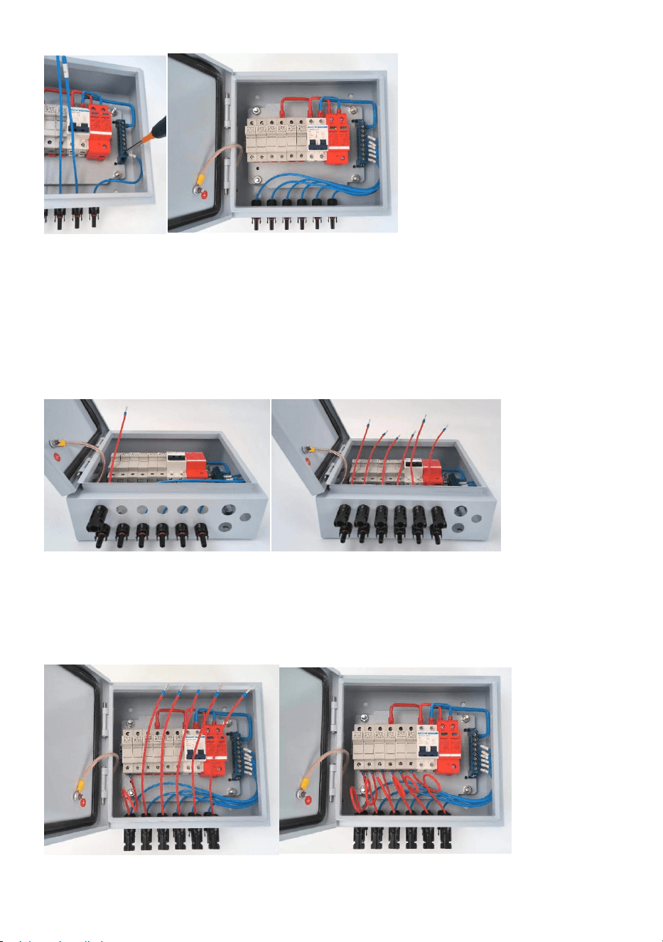
(3) Wiring No.6 cable with terminal block’s position No.1;
(4) Wiring the rest of cables as (3)process step by step,the finial status as
follows picture showed.
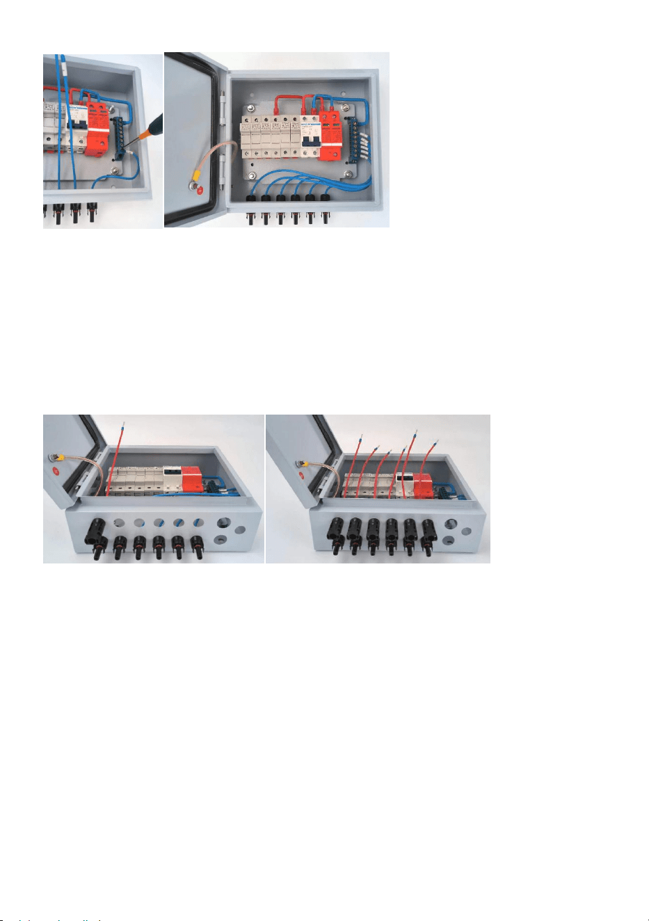
4. Wiring Input+ MC4 female connector with cable
(1) Mounting No.1 cable on the picture 12 showed position,fix with nut;
(2) Mounting the rest of cables on the picture 13 showed position,fix with
nut.
(3) Wiring No.1 cable with No.1 fuse holder,fix the fuse holder screw;
(4) Wiring the rest of cables as (3)process step by step,the finial status as
follows picture showed.
- 9 -
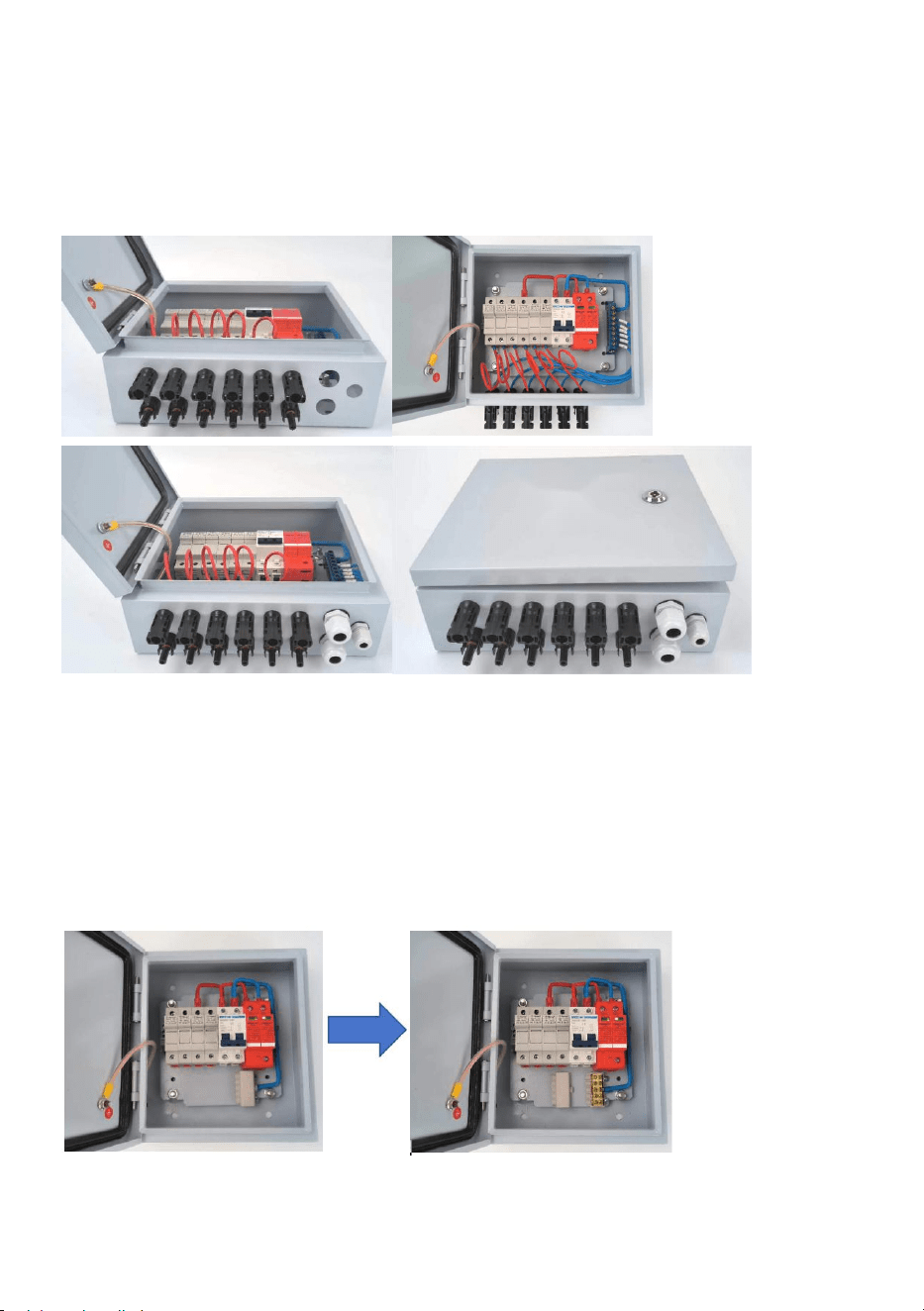
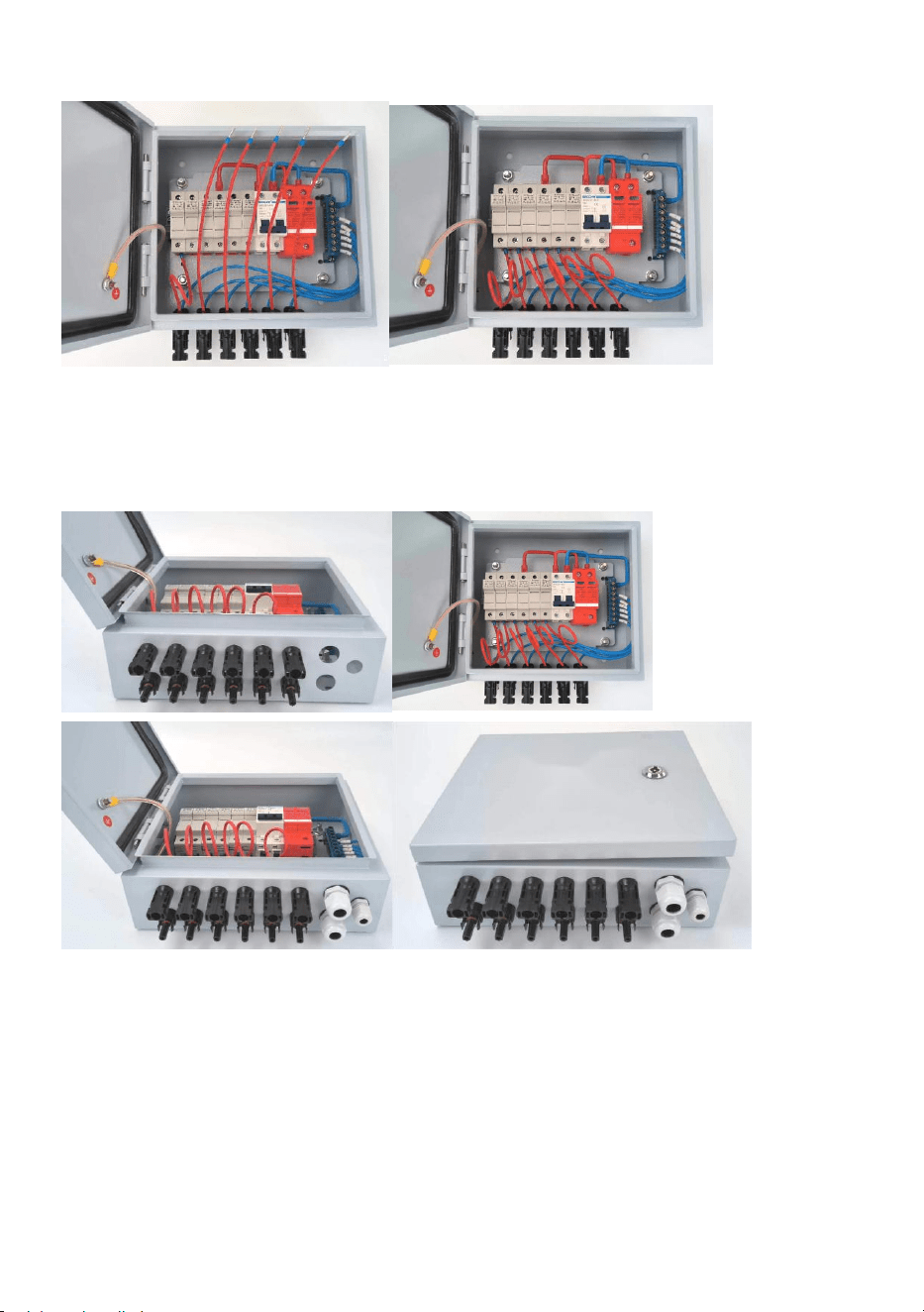
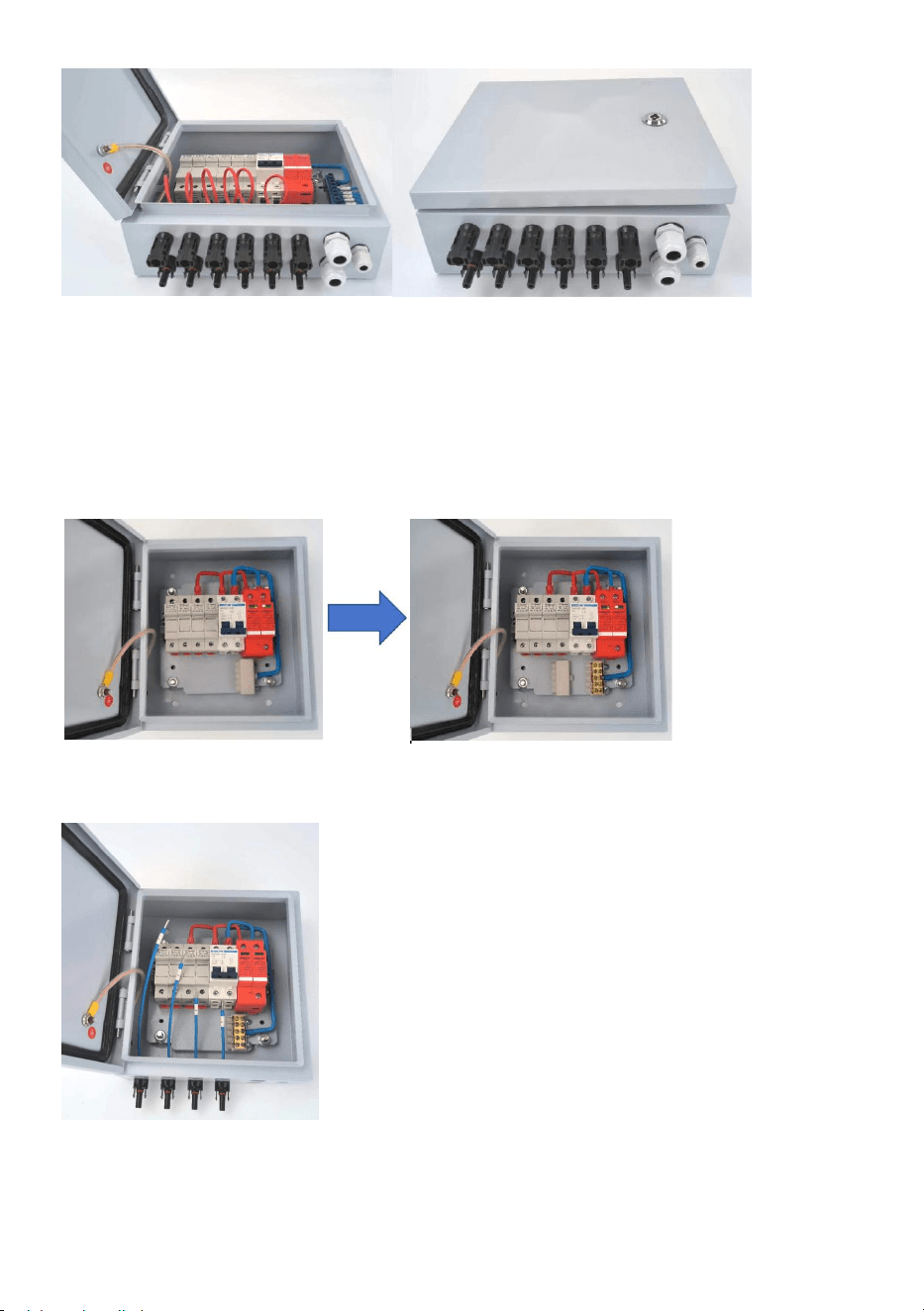
5. Mounting output cable glands and earthing cable gland.
(1) Mounting 2pcs PG13.5 cable glands on marked 2 positions;
(2) Mounting 1pcs PG9 cable gland on marked position,the finial status as
follows picture showed
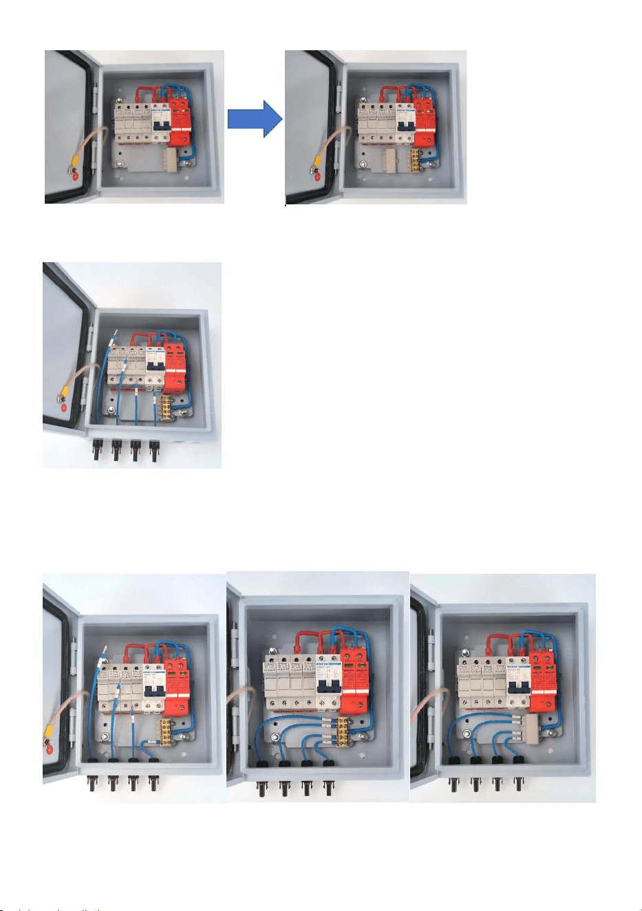
Tips:for 4ways PV combiner box,here have some different steps on wiring
Input- MC4 male connector with cable compare with 6ways PV combiner
box.the rest of process keep same.
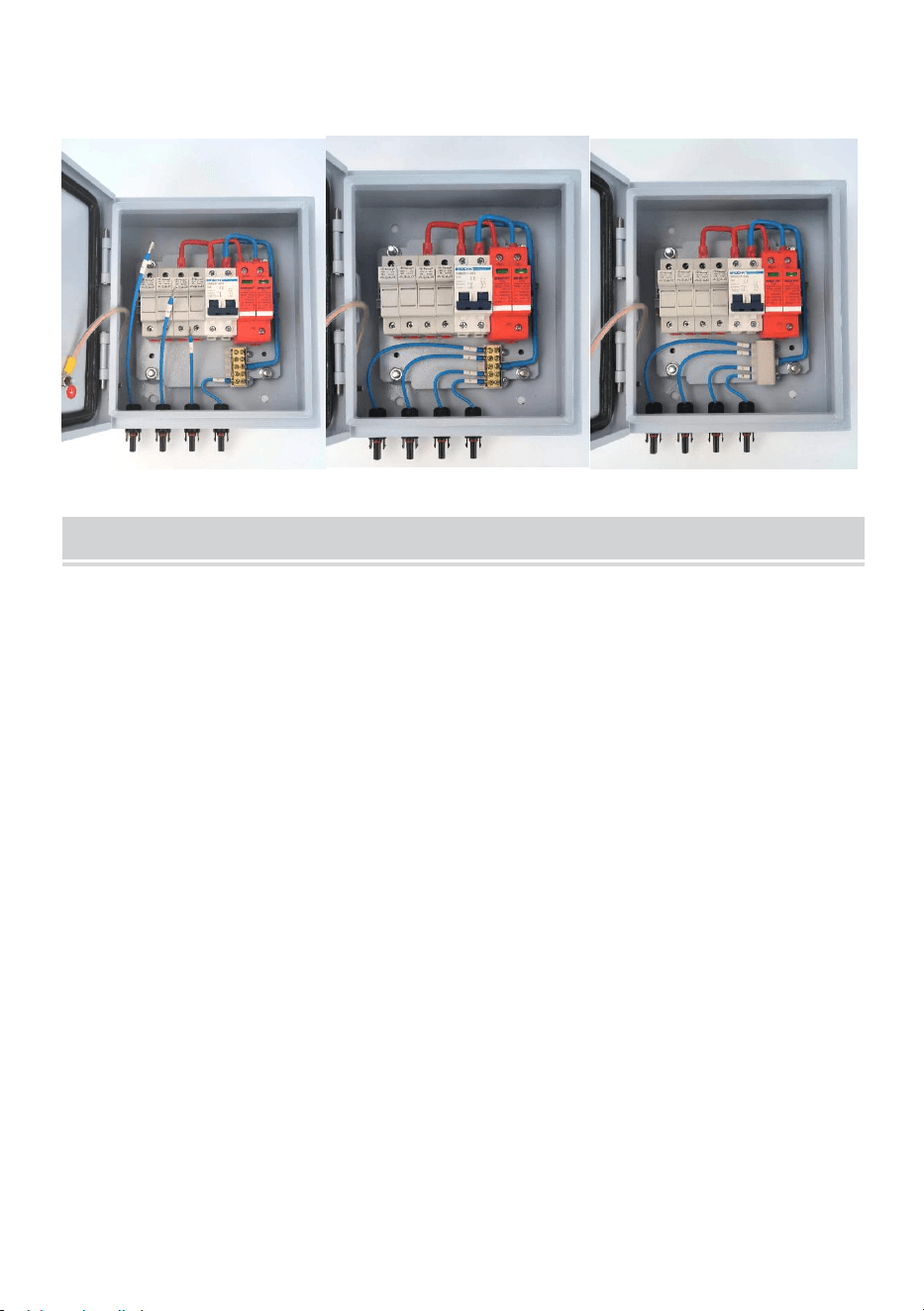
(1) Open terminal block’s cover as follows:
(2)Mounting 4pcs Input- MC4 male connector with cable and fix with nut as
same as the above process;
- 10 -
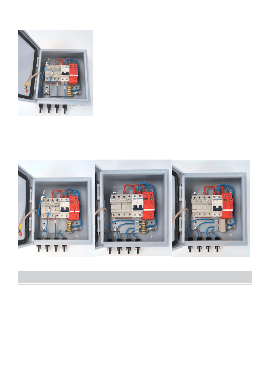
(3) Wiring No.4 cable with terminal block’s position No.1;
(4) Wiring the rest of cables as (3)process step by step,close the terminal
block cover,the finial status as follows showed.
Installation & Use
Installation: Adopts matched screws fix 4 mounting buckles on box back
side’s 4 holes.Users can select correct position mount the combiner box on
the wall or panel.
Fast connection
(1) In order to improve the connection of rapidity and convenience, use key
to open the door of combiner box ,the photovoltaic array input wire
connected to the corresponding terminal,pay attention to the photovoltaic
array input line of the positive and negative polarity connection.
- 11 -
(2) The combiner is a independent one sets of photovoltaic array
input/output design,through reasonable photovoltaic array input
connection, output power will be one way, to match the one way
independent input controller is used.
(3) When users connection system, please make sure that all the lines and
equipment is reliable.
Over-current protection
When the pv module input current is too large, the fuse will break for
protection; In addition, miniature circuit breaker also can prevent the
system from current is too large, have over-current protection function.
WARNING!
It is strictly prohibited to work in touch fuse,
inspection or replacement is required before the
fuse will dc circuit breaker off; Must be replaced with
the original model of the same magnitude fuse.
Over-voltage protection
When the pv module input voltage is high, the miniature circuit breaker
will automatically disconnect,have overvoltage protection function.
Appendix
Quality assurance
This product quality assurance period 1 year, otherwise stipulated in the
contract period of the contract shall prevail.
Evidence
Products in the quality assurance period require customers to buy the
products show the invoice and date. At the same time the product of the

- 12 -
trademark shall be clearly visible, or shall have the right to not be quality
assurance.
The following situation, this company has the right to not to quality
assurance:
1.Man-made damage to the equipment
2.Wrong installation and use
3.When using the maximum limit parameters beyond equipment
requirements;
4.Abnormal natural environment damage caused;
5.Beyond that in this manual are very bad environment operation;
6.Beyond the relevant international standards specified in the installation
and use of range.
Address:Baoshanqu Shuangchenglu 803long 11hao 1602A-1609shi
Shanghai
Imported to AUS: SIHAO PTY LTD, 1 ROKEVA STREETEASTWOOD
NSW 2122 Australia
Imported to USA: Sanven Technology Ltd., Suite 250, 9166 Anaheim
Place, Rancho Cucamonga, CA 91730
REP
EC
SHUNSHUN GmbH
Römeräcker 9 Z2021, 76351
Linkenheim-Hochstetten, Germany
REP
UK
Pooledas Group Ltd
Unit 5 Albert Edward House, The
Pavilions Preston, United Kingdom
Made In China

- 13 -


Technique Certificat d'assistance et de garantie électronique
www.vevor.com/support
COFFRET DE COMBINAISON PV
Modèle : SP-HL-S252310-15A
SP-HL-S252810-10A
SP-HL-S252810-15A
We continue to be committed to provide you tools with competitive price.
"Save Half", "Half Price" or any other similar expressions used by us only represents an
estimate of savings you might benefit from buying certain tools with us compared to the major
top brands and does not necessarily mean to cover all categories of tools offered by us. You
are kindly reminded to verify carefully when you are placing an order with us if you are
actually saving half in comparison with the top major brands.

- 1 -
Modèle : SP-HL-S252310-15A / SP- HL -S252810-10A /
SP-HL-S252810-15A
Have product questions? Need technical support? Please feel free to
contact us:
Technical Support and E-Warranty Certificate
www.vevor.com/support
NEED HELP? CONTACT US!
PV COMBINER BOX

- 2 -
This is the original instruction, please read all manual instructions
carefully before operating. VEVOR reserves a clear interpretation of our
user manual. The appearance of the product shall be subject to the
product you received. Please forgive us that we won't inform you again if
there are any technology or software updates on our product.
Avertissement - Pour réduire le risque de blessure, l'utilisateur
doit lire attentivement le manuel d'instructions.
Cet appareil est conforme à la partie 15 des règles de la FCC.
Son fonctionnement est soumis aux deux conditions
suivantes : (1) Cet appareil ne doit pas provoquer
d'interférences nuisibles et (2) Cet appareil doit accepter toute
interférence reçue, y compris les interférences pouvant
entraîner un fonctionnement indésirable.
Ce produit est soumis aux dispositions de la directive
européenne 2012/19/CE. Le symbole représentant une
poubelle à roulettes barrée indique que le produit doit faire
l'objet d'une collecte sélective des déchets dans l'Union
européenne. Cela s'applique au produit et à tous les
accessoires marqués de ce symbole. Les produits marqués
comme tels ne peuvent pas être jetés avec les déchets
ménagers normaux, mais doivent être déposés dans un point
de collecte pour le recyclage des appareils électriques et
électroniques.
Identification and Description
Afin de mieux utiliser le produit, veuillez lire les instructions suivantes :
- 3 -
AVERTISSEMENT !
Ce symbole d'identification pour une utilisation
informelle peut être dangereux pour la sécurité des
utilisateurs ou peut causer des dommages matériels
importants.
Installation avant utilisation, veuillez lire ce manuel.
AVERTISSEMENT !
Toutes les opérations et connexions de lignes
nécessitent l'intervention d'un professionnel.
AVERTISSEMENT !
Veuillez prêter attention à la sécurité des personnes et
des équipements.
AVERTISSEMENT!
Veuillez noter que l'entrée du réseau photovoltaïque de
positif et polarité négative et la puissance totale de
sortie des polarités positive et négative.
AVERTISSEMENT !
Installation ou connexion pv modules , veuillez noter
PV modules haut tension , éviter produire un choc
danger .
AVERTISSEMENT !
Assurez-vous que la connexion de fixation, pour
l'utilisateur d'utiliser un câblage inapproprié ou une
perte de câble causée par une instabilité, la société
Vevor n'assume aucune responsabilité.
Product Introduction
Système de production d'énergie photovoltaïque, afin de réduire le module
photovoltaïque et l'onduleur entre les câbles de connexion, une
- 4 -
maintenance pratique, réduire les pertes et améliorer la sécurité et la
fiabilité du produit, nécessite généralement l'ajout du module
photovoltaïque et de l'onduleur entre le dispositif de confluence.
La boîte de jonction photovoltaïque, en plus d'avoir la fonction de bus
photovoltaïque extérieur, doit en même temps avoir également une
contre-attaque de courant, une protection contre les surintensités, une
protection contre les surtensions, une protection contre la foudre et une
série de fonctions de protection parfaites.
Cette société produit la boîte de jonction photovoltaïque avec les diverses
exigences fonctionnelles ci-dessus, et le réseau photovoltaïque (PV), à
partir d'un onduleur de type réseau prenant en charge l'utilisation, peut
former un ensemble complet de solutions de système de production
d'énergie photovoltaïque.
Sélectionnez la boîte de jonction photovoltaïque, l'utilisateur peut en
fonction de la plage de tension d'entrée de l'onduleur arrière, de la taille de
la puissance de sortie, d'un certain nombre de spécifications de la même
série de modules photovoltaïques, de la série de modules photovoltaïques
à composition parallèle, coordonner l'accès à la boîte de jonction
photovoltaïque (voir Figure 1) bus, puis après le contrôle du disjoncteur et
la protection du dispositif de protection contre la foudre après la sortie pour
l'utilisation de l'onduleur de niveau.
La figure 2 montre les pièces associées et leurs spécifications.
Figure 1
- 5 -
Figure 2
01---Boîte métallique étanche
02---4pcs/6pcs Porte-fusible DC500V avec fusible 10/15A
03--- Disjoncteur différentiel 63A/ 125A 2P DC500V
04--- SU6-40KA 2P DC500V SPD
05---Barre neutre
06 --- Connecteur femelle solaire 4 pièces/6 pièces
07 --- Connecteur mâle solaire 4 pièces/6 pièces
08 --- 2 presse-étoupes de sortie PG16
09---Presse-étoupe de mise à la terre PG9
Production Specification
Modèle
SP-HL-S252310
-15A
SP-HL-S252810
-10A
SP-HL-S252810
-15A
Numéros d'entrée du champ
PV
4
6
6
Courant maximal d'un seul
champ PV
1 5A
10A
15A
Fusible pour un seul champ
PV
1 5A
10A
15A
Taille de fil d'un seul
panneau PV
2,5 mm
2
Numéros de sortie
1
Courant de sortie maximal
6 0A
6 0 Un
90A
Taille du fil de sortie
10 mm
2
1 0 mm
2
1 6 mm
2

- 6 -
Tension de sortie maximale
500 VCC
Disjoncteur de sortie CC
Oui
Niveau de protection
IP 6 6
Plage de température
- 30℃ ~ +60℃
Mode de refroidissement
Naturel refroidissement
Protection SPD
Oui
Taille du fil de terre
≥ 2,5 mm²
SP-HL-S252310-15A Schéma de câblage du boîtier de combinaison PV à
4 entrées et 1 sortie comme suit :
SP-HL-S252810-10A et SP-HL-S252810-15A Schéma de câblage du
boîtier de combinaison PV à 6 entrées et 1 sortie comme suit :
PV Combiner Box Assembly Process
- 7 -
6. Liste des accessoires :
(9) boîte de combinaison PV à moitié finie --- 1 pièces ;
(10)Entrée - Connecteur mâle MC4 avec câble ---- 4 pièces (pour boîtier
de combinaison PV 4 voies) / 6 pièces (pour boîtier de combinaison PV 6
voies) ; Conseils : chaque câble a une longueur différente, il y a une
étiquette numérotée sur chaque câble, remarquez pour distinguer.
(11) Entrée + connecteur femelle MC4 avec câble ---- 4 pièces (pour boîtier
de combinaison PV 4 voies) / 6 pièces (pour boîtier de combinaison PV 6
voies) ; Conseils : chaque câble garde la même longueur.
(12)Sortie + presse-étoupe PG13,5 -- 1 pièce ;
(13)Sortie - Presse-étoupe PG13,5 - 1 pièce ;
(14)Presse-étoupe de mise à la terre PG9 - 1 pièce ;
(15)Outil MC4 --- 1 pièce ;
(16)Sac de supports de montage mural --- 1 jeu ;
7. Travaux préparatoires
(6) Entrée lâche - Écrou de montage du connecteur femelle MC4 ;
(7) Entrée lâche + écrou de montage du connecteur femelle MC4 ;
(8) - étoupes 3 pièces en vrac ;
(9) du bornier desserrées , assurez-vous que le processus de câblage
suivant est facile à réparer ;
- 8 -
(10)- fusibles desserrées , assurez-vous que le processus de câblage
suivant est facile à réparer ;
8. Entrée de câblage - Connecteur mâle MC4 avec câble
(5) Montage du câble n°1 sur la photo 8 montrant la position, fixer avec un
écrou ;
(6) Le montage du reste des câbles sur la photo 9 montre la position,
fixez-le avec un écrou. Le numéro de câble de gauche à droite doit être le
n° 1 à n° 6 ;
(7) Câblage câble n°6 avec position du bornier n°1 ;
(8) Câblage du reste des câbles selon le processus (3) étape par étape,
l'état final est le suivant comme le montre l'image.

- 9 -
9. Entrée de câblage + connecteur femelle MC4 avec câble
(5) Montage du câble n°1 sur la photo 12 montré en position, fixer avec
un écrou ;
(6) Le montage du reste des câbles sur la photo 13 montre la position, fixer
avec un écrou.
(7) Câblage du câble n°1 avec le porte-fusible n°1, fixez la vis du
porte-fusible ;
(8) Câblage du reste des câbles selon le processus (3) étape par étape,
l'état final est le suivant comme le montre l'image.
- 10 -
10.Montage des presse-étoupes de sortie et de mise à la terre.
(5) Montage de 2 presse-étoupes PG13,5 sur 2 positions marquées ;
(6) Montage d'un presse-étoupe PG9 sur la position marquée, l'état final
est le même que celui montré sur l'image suivante
Conseils : pour le boîtier de combinaison PV à 4 voies, voici quelques
étapes différentes pour le câblage de l'entrée - connecteur mâle MC4 avec
câble par rapport au boîtier de combinaison PV à 6 voies. Le reste du
processus reste le même.
(2) du bornier comme suit :
- 11 -
(2) Montage de 4 connecteurs d'entrée MC4 mâles avec câble et fixation
avec écrou comme dans le processus ci-dessus ;
(7) Câblage câble n°4 avec position du bornier n°1 ;
(8) Câblage du reste des câbles comme (3) processus étape par étape,
fermez le couvercle du bornier, l'état final est indiqué comme suit.

- 12 -
Installation & Use
Installation: Adopte des vis assorties pour fixer 4 boucles de montage sur
les 4 trous à l'arrière de la boîte. Les utilisateurs peuvent sélectionner la
position correcte pour monter le boîtier de combinaison sur le mur ou le
panneau.
Rapide connexion
(4) Afin d' améliorer le connexion de rapidité et commodité , utilisation clé à
ouvrir le porte du boîtier de combinaison, le fil d'entrée du réseau
photovoltaïque connecté au correspondant terminal , payer attention à le
photovoltaïque tableau saisir doubler de le positif et négatif polarité
connexion .
(5) Le combinateur est un indépendant un ensemble de photovoltaïque
tableau entrée / sortie conception , à travers raisonnable photovoltaïque
tableau connexion d'entrée , sortir pouvoir sera un chemin , à
correspondre celui chemin indépendant saisir contrôleur est utilisé .
(6) Quand utilisateurs connexion système , s'il vous plaît faire bien sûr
que tous le lignes et équipement est fiable .
Surintensité protection
Quand le PV module saisir actuel est aussi grand , le fusible volonté
casser pour la protection ; Dans De plus, un disjoncteur miniature peut
également empêcher le système de passer sous tension. est aussi grand ,
avoir surintensité protection fonction.
AVERTISSEMENT !
Il est strictement interdit à travail dans touche
fusible , inspection ou remplacement est requis
avant le fusible volonté dc disjoncteur éteint ; Doit
être remplacé par le modèle d'origine du même

- 13 -
ampleur fusible .
Surtension protection
Quand le PV module saisir tension est haut , le miniature circuit
briseur sera automatiquement déconnecter , avoir surtension protection
fonction .
Appendix
Assurance qualité
Cette période d'assurance qualité du produit est d'un an, sauf disposition
contraire stipulée dans la période contractuelle du contrat qui prévaudra.
Preuve
Les produits en période d'assurance qualité nécessitent Les clients qui
achètent des produits doivent montrer la facture et la date. Dans le même
temps, la marque du produit doit être clairement visible, sinon elle aura le
droit de ne pas être garantie de qualité.
Dans la situation suivante, cette entreprise a le droit de ne pas
assurer la qualité :
1. Dommages causés par l'homme à l'équipement
2. Mauvaise installation et utilisation
3. Lors de l’utilisation des paramètres de limite maximale au-delà des
exigences de l’équipement ;
4. Dommages anormaux causés à l’environnement naturel ;
5. Au-delà de ce qui est décrit dans ce manuel , il existe un très mauvais
environnement de fonctionnement ;
- 14 -
6. Au-delà des normes internationales pertinentes spécifiées dans
l'installation et l'utilisation de la gamme .
Adresse : Baoshanqu Shuangchenglu 803long 11hao 1602A-1609shi
Shanghai
Importé en Australie : SIHAO PTY LTD, 1 ROKEVA STREET, ASTWOOD
NSW 2122 Australie
Importé aux États-Unis : Sanven Technology Ltd., Suite 250, 9166
Anaheim Place, Rancho Cucamonga, CA 91730
REP
EC
SHUNSHUN GmbH
Römeräcker 9 Z2021, 76351
Linkenheim-Hochstetten, Germany
REP
UK
Pooledas Group Ltd
Unit 5 Albert Edward House, The
Pavilions Preston, United Kingdom
Fabriqué en Chine


Technisch Support und E-Garantie-Zertifikat
www.vevor.com/support
PV-COMBINER-BOX
Modell : SP-HL-S252310-15A
SP-HL-S252810-10A
SP-HL-S252810-15A
We continue to be committed to provide you tools with competitive price.
"Save Half", "Half Price" or any other similar expressions used by us only represents an
estimate of savings you might benefit from buying certain tools with us compared to the major
top brands and does not necessarily mean to cover all categories of tools offered by us. You
are kindly reminded to verify carefully when you are placing an order with us if you are
actually saving half in comparison with the top major brands.


- 1 -
Modell : SP-HL-S252310-15A / SP - HL-S252810-10A /
SP-HL-S252810-15A
Have product questions? Need technical support? Please feel free to
contact us:
Technical Support and E-Warranty Certificate
www.vevor.com/support
NEED HELP? CONTACT US!
PV COMBINER BOX

- 2 -
This is the original instruction, please read all manual instructions
carefully before operating. VEVOR reserves a clear interpretation of our
user manual. The appearance of the product shall be subject to the
product you received. Please forgive us that we won't inform you again if
there are any technology or software updates on our product.
Warnung: Um das Verletzungsrisiko zu verringern, muss der
Benutzer die Bedienungsanleitung sorgfältig lesen.
Dieses Gerät entspricht Teil 15 der FCC-Bestimmungen. Der
Betrieb unterliegt den folgenden beiden Bedingungen: (1)
Dieses Gerät darf keine schädlichen Störungen verursachen
und (2) dieses Gerät muss alle empfangenen Störungen
akzeptieren, einschließlich Störungen, die einen
unerwünschten Betrieb verursachen können.
Dieses Produkt unterliegt den Bestimmungen der
europäischen Richtlinie 2012/19/EU. Das Symbol einer
durchgestrichenen Mülltonne weist darauf hin, dass das
Produkt in der Europäischen Union einer getrennten
Müllentsorgung unterliegt. Dies gilt für das Produkt und alle mit
diesem Symbol gekennzeichneten Zubehörteile. So
gekennzeichnete Produkte dürfen nicht im normalen Hausmüll
entsorgt werden, sondern müssen an einer Sammelstelle für
das Recycling von elektrischen und elektronischen Geräten
abgegeben werden.
Identification and Description
Um das Produkt besser nutzen zu können, lesen Sie bitte das folgende
Anweisungssymbol:
- 3 -
WARNUNG !
Diese Symbolkennzeichnung für den informellen
Betrieb kann die Sicherheit des Benutzers gefährden
oder zu erheblichen Hardwareschäden führen.
Bitte lesen Sie dieses Handbuch vor der Installation.
WARNUNG !
Für alle Vorgänge und Leitungsverbindungen ist
Fachpersonal erforderlich.
WARNUNG !
Bitte achten Sie auf die Sicherheit von Person und
Ausrüstung.
WARNUNG!
Bitte beachten Sie, dass der Photovoltaik-Eingang von
Plus- und Minuspol negative Polarität und die
Gesamtausgabe der positiven und negativen Polarität.
WARNUNG !
Installation oder Anschluss PV Module , bitte beachten
Sie pv Module hoch Spannung , vermeiden Schock
erzeugen Gefahr .
WARNUNG !
Stellen Sie sicher, dass die Befestigung des
Anschlusses nicht beschädigt wird. Verwenden Sie das
Kabel nicht unsachgemäß oder verwenden Sie es
nicht instabil, sodass es zu Verbindungsverlusten
kommt. Vevor übernimmt hierfür keine Verantwortung.
Product Introduction
Um bei Photovoltaik-Stromerzeugungssystemen die Anzahl der
Verbindungskabel zwischen Photovoltaikmodul und Wechselrichter zu
- 4 -
verringern, die Wartung zu vereinfachen, Verluste zu reduzieren und die
Sicherheit und Zuverlässigkeit des Produkts zu verbessern, ist es im
Allgemeinen erforderlich, zwischen Photovoltaikmodul und Wechselrichter
ein Zusammenflussgerät hinzuzufügen.
Photovoltaik-Anschlussdosen müssen neben der Funktion der externen
PV-Sammelschiene auch über eine Reihe perfekter Schutzfunktionen wie
Gegenstrom-, Überstrom-, Überspannungs- und Blitzschutz verfügen.
Dieses Unternehmen produziert Photovoltaik-Anschlusskästen mit den
oben genannten verschiedenen Funktionsanforderungen sowie
Photovoltaik-(PV-)Netze, die vom Netzwechselrichter unterstützt werden
und so ein komplettes Set an Systemlösungen für die
Photovoltaik-Stromerzeugung bilden.
Wählen Sie eine Photovoltaik-Anschlussdose aus. Der Benutzer kann
entsprechend dem Eingangsspannungsbereich des Wechselrichters am
hinteren Ende, der Ausgangsleistungsgröße und einer bestimmten Anzahl
von Spezifikationen derselben PV-Modulserie die parallel
zusammengestellten PV-Modulserien koordinieren und auf die
Photovoltaik-Anschlussdose (siehe Abbildung 1) zugreifen. Anschließend
kann er den Ausgang nach der Steuerung des Leistungsschalters und dem
Blitzschutzgerät schützen, um den Wechselrichter zu verwenden.
Abbildung 2 zeigt zugehörige Teile und deren Spezifikationen.
Abbildung 1

- 5 -
Abbildung 2
01 --- Wasserdichte Metallbox
02 --- 4 Stück/6 Stück DC500V Sicherungshalter mit 10/15A Sicherung
03--- 63 A/ 125 A 2P DC500 V Sicherungsautomat
04--- SU6-40KA 2P DC500V Überspannungsschutz
05---Neutraler Balken
06 --- 4 Stück/6 Stück Solar-Buchsenstecker
07 --- 4 Stück/6 Stück Solar-Stecker
08 --- 2 Stück Ausgang PG16 Kabelverschraubung
09---Erdung PG9 Kabelverschraubung
Production Specification
Modell
SP-HL-S252310
-15A
SP-HL-S252810
-10A
SP-HL-S252810
-15A
PV-Array-Eingangsnummer
n
4
6
6
Max. Stromstärke eines
einzelnen PV-Arrays
1 5A
10A
15A
Einzelne
PV-Array-Sicherung
1 5A
10A
15A
Kabelgröße für einzelne
PV-Arrays
2,5 mm
2
Ausgabenummern
1
Max. Ausgangsstrom
6 0A
6 0 A
90A
Ausgangskabelgröße
10 mm
2
1 0 mm
2
1 6 mm
2
- 6 -
Max. Ausgangsspannung
500 V Gleichstrom
DC-Ausgangsschutzschalter
Ja
Schutzniveau
IP 6 6
Temperaturbereich
30 ℃ ~ + 60 ℃
Kühlweg
Natürlich Kühlung
SPD-Schutz
Ja
Größe des Erdungskabels
≥ 2,5 mm²
SP-HL-S252310-15A Der Schaltplan für die PV-Combinerbox mit 4
Eingängen und 1 Ausgang lautet wie folgt:
SP-HL-S252810-10A und SP-HL-S252810-15A Der Schaltplan für die
PV-Combinerbox mit 6 Eingängen und 1 Ausgang lautet wie folgt:
PV Combiner Box Assembly Process
- 7 -
11.Zubehörliste:
(17)halbfertige PV-Combiner-Box --- 1 Stück;
(18)Eingang – MC4-Stecker mit Kabel – 4 Stück (für
4-Wege-PV-Combiner-Box)/6 Stück (für 6-Wege-PV-Combiner-Box); Tipps:
Jedes Kabel hat eine andere Länge, auf jedem Kabel befindet sich ein
Nummernetikett, zur Unterscheidung ist darauf zu achten.
(19)Eingang + MC4-Buchse mit Kabel ---- 4 Stück (für
4-Wege-PV-Combiner-Box)/6 Stück (für 6-Wege-PV-Combiner-Box); Tipps:
Jedes Kabel hat die gleiche Länge.
(20)Ausgang + PG13.5-Kabelverschraubung – 1 Stück;
(21)Ausgang – PG13.5-Kabelverschraubung – 1 Stück;
(22)Erdungskabelverschraubung PG9 – 1 Stück;
(23)MC4-Werkzeug – 1 Stück;
(24)Tasche mit Wandmontagehalterungen – 1 Satz;
- 8 -
12.Vorarbeit
(11) Befestigungsmutter des Eingangs -MC4-Buchsensteckers ;
(12)Befestigungsmutter des losen Input+ MC4-Buchsensteckers ;
(13)3 lose Kabelverschraubungen , Befestigungsmuttern;
(14)des Klemmenblocks . Stellen Sie sicher, dass der folgende
Verdrahtungsvorgang leicht zu beheben ist.
(15)Stellen Sie sicher, dass die Eingangsbefestigungsschrauben der losen
Sicherungshalter beim folgenden Verdrahtungsvorgang leicht zu beheben
sind.
13.Verdrahtungseingang - MC4-Stecker mit Kabel
(9) Montage des Kabels Nr. 1 (siehe Abbildung 8), Position mit Mutter
fixieren;
(10)Montieren Sie die restlichen Kabel an der in Bild 9 gezeigten Position
und befestigen Sie sie mit einer Mutter. Die Kabelnummern von links nach
rechts sind Nr. 1 bis Nr. 6.
(11) Verkabelung Nr. 6, Kabel mit Klemmenblockposition Nr . 1;
(12)Verdrahten Sie die restlichen Kabel wie in (3) beschrieben Schritt für
Schritt. Der endgültige Status ist im folgenden Bild dargestellt.
- 9 -
14.Verkabelung Eingang+ MC4 Buchse mit Kabel
(9) Montage von Kabel Nr. 1, in der auf Bild 12 gezeigten Position, mit
Mutter fixieren;
(10)Montieren Sie die restlichen Kabel in der in Bild 13 gezeigten Position
und befestigen Sie sie mit einer Mutter.
(11) Verdrahten Sie Kabel Nr. 1 mit Sicherungshalter Nr. 1 und befestigen
Sie die Schraube des Sicherungshalters.
(12)Verdrahten Sie die restlichen Kabel wie in (3) beschrieben Schritt für
Schritt. Der endgültige Status ist im folgenden Bild dargestellt.
15.Montage von Ausgangskabelverschraubungen und
- 10 -
Erdungskabelverschraubung.
(9) Montieren Sie 2 Stück PG13.5-Kabelverschraubungen an den
markierten 2 Positionen;
(10)Montage einer PG9-Kabelverschraubung an der markierten Stelle. Der
Endzustand ist wie im folgenden Bild dargestellt.
Tipps: Für die 4-Wege-PV-Combiner-Box gibt es einige unterschiedliche
Schritte zur Verdrahtung des Eingangs – MC4-Stecker mit Kabel im
Vergleich zur 6-Wege-PV-Combiner-Box. Der Rest des Vorgangs bleibt
gleich.
(3) des Klemmenblocks wie folgt:
(2) Montieren Sie 4 Stück Eingang – MC4-Stecker mit Kabel und
- 11 -
befestigen Sie sie mit der Mutter wie oben beschrieben.
(11) Verkabelung Nr. 4, Kabel mit Klemmenblockposition Nr . 1;
(12)Verdrahten Sie die restlichen Kabel wie in (3) beschrieben Schritt für
Schritt. Schließen Sie die Abdeckung des Klemmenblocks. Der endgültige
Status wird wie folgt angezeigt.
Installation & Use
Installation: Mit passenden Schrauben werden die 4 Montageschnallen an
den 4 Löchern auf der Rückseite der Box befestigt. Der Benutzer kann die
richtige Position für die Montage der Combiner-Box an der Wand oder dem
Panel auswählen.
Schnell Verbindung
(7) Um zu verbessern Die Verbindung von Schnelligkeit Und
- 12 -
Bequemlichkeit , Verwendung Schlüssel Zu offen Die Tür der
Combiner-Box, das Photovoltaik-Array-Eingangskabel an die
entsprechende Terminal , bezahlen Aufmerksamkeit Zu Die Photovoltaik
Anordnung Eingang Linie von das Positive Und Negativ Polarität
Verbindung .
(8) Der Mähdrescher Ist ein unabhängiger ein Satz von Photovoltaik
Anordnung Eingang / Ausgang Gestaltung , durch vernünftig Photovoltaik
Anordnung Eingangsanschluss , Ausgabe Leistung wird eins sein Weg ,
zu übereinstimmen der Eine Weg unabhängig Eingang Regler Ist
gebraucht .
(9) Wann Benutzer Verbindung System , bitte machen Sicher Das alle
Die Linien und Ausstattung Ist zuverlässig .
Überstrom Schutz
Wann Die pv Modul Eingang aktuell Ist zu groß , die Sicherung Wille
brechen zum Schutz ; In Darüber hinaus kann ein
Miniatur-Leistungsschalter auch verhindern, dass das System überlastet
wird. Ist zu groß , haben Überstrom Schutz Funktion.
WARNUNG !
Es Ist streng verboten Zu arbeiten In berühren
Sicherung , Inspektion oder Ersatz Ist erforderlich
vor Die Sicherung Wille Gleichstrom
Leistungsschalter aus; Muss durch das
Originalmodell des gleichen ersetzt werden Größe
Sicherung .
Überspannung Schutz
Wann Die pv Modul Eingang Stromspannung Ist hoch , die Miniatur
Schaltung Leistungsschalter wird automatisch trennen , haben

- 13 -
Überspannung Schutz -Funktion .
Appendix
Qualitätssicherung
Die Qualitätssicherungszeit dieses Produkts beträgt ein Jahr.
Andernfalls gilt die im Vertrag festgelegte Vertragslaufzeit.
Beweis
Produkte im Qualitätssicherungszeitraum benötigen Kunden müssen
beim Kauf der Produkte die Rechnung und das Datum vorzeigen.
Gleichzeitig muss das Markenzeichen des Produkts deutlich sichtbar sein,
andernfalls besteht das Recht, keine Qualitätssicherung zu verwenden.
In folgenden Fällen hat das Unternehmen das Recht, die
Qualitätssicherung einzustellen:
1. Vom Menschen verursachte Schäden an der Ausrüstung
2. Falsche Installation und Verwendung
3. Bei Verwendung der maximalen Grenzparameter über die
Geräteanforderungen hinaus ;
4. Ungewöhnliche natürliche Umweltschäden ;
5. Darüber hinaus werden in diesem Handbuch sehr schlechte
Betriebsumgebungen beschrieben.
6. Über die Installation und Nutzung des Sortiments hinausgehende,
einschlägige internationale Normen gelten .
Adresse: Baoshanqu Shuangchenglu 803long 11hao 1602A-1609shi
Shanghai
Nach AUS importiert: SIHAO PTY LTD, 1 ROKEVA
STREETEASTWOOD NSW 2122 Australien
Importiert in die USA: Sanven Technology Ltd., Suite 250, 9166 Anaheim
Place, Rancho Cucamonga, CA 91730

- 14 -
REP
EC
SHUNSHUN GmbH
Römeräcker 9 Z2021, 76351
Linkenheim-Hochstetten, Germany
REP
UK
Pooledas Group Ltd
Unit 5 Albert Edward House, The
Pavilions Preston, United Kingdom
In China hergestellt


Tecnico Supporto e certificato di garanzia elettronica
www.vevor.com/support
QUADRO COMBINATORE FOTOVOLTAICO
Modello : SP-HL-S252310-15A
Codice articolo: SP-HL-S252810-10A
Codice articolo: SP-HL-S252810-15A
We continue to be committed to provide you tools with competitive price.
"Save Half", "Half Price" or any other similar expressions used by us only represents an
estimate of savings you might benefit from buying certain tools with us compared to the major
top brands and does not necessarily mean to cover all categories of tools offered by us. You
are kindly reminded to verify carefully when you are placing an order with us if you are
actually saving half in comparison with the top major brands.


- 1 -
Modello : SP-HL-S252310-15A / SP - HL-S252810-10A /
SP-HL-S252810-15A
Have product questions? Need technical support? Please feel free to
contact us:
Technical Support and E-Warranty Certificate
www.vevor.com/support
NEED HELP? CONTACT US!
PV COMBINER BOX
- 2 -
This is the original instruction, please read all manual instructions
carefully before operating. VEVOR reserves a clear interpretation of our
user manual. The appearance of the product shall be subject to the
product you received. Please forgive us that we won't inform you again if
there are any technology or software updates on our product.
Attenzione: per ridurre il rischio di lesioni, l'utente deve leggere
attentamente il manuale di istruzioni.
Questo dispositivo è conforme alla Parte 15 delle Norme FCC.
Il funzionamento è soggetto alle due condizioni seguenti: (1)
Questo dispositivo non può causare interferenze dannose e
(2) Questo dispositivo deve accettare qualsiasi interferenza
ricevuta, comprese le interferenze che possono causare un
funzionamento indesiderato.
Questo prodotto è soggetto alle disposizioni della Direttiva
Europea 2012/19/CE. Il simbolo raffigurante un bidone della
spazzatura barrato indica che il prodotto richiede la raccolta
differenziata dei rifiuti nell'Unione Europea. Ciò si applica al
prodotto e a tutti gli accessori contrassegnati con questo
simbolo. I prodotti contrassegnati come tali non possono
essere smaltiti con i normali rifiuti domestici, ma devono
essere portati in un punto di raccolta per il riciclaggio di
dispositivi elettrici ed elettronici
Identification and Description
Per utilizzare al meglio il prodotto, leggere attentamente le seguenti
istruzioni simbolo:

- 3 -
AVVERTIMENTO !
L'identificazione di questo simbolo per operazioni
informali potrebbe essere pericolosa per la sicurezza
degli utenti o potrebbe causare gravi danni
all'hardware.
Prima dell'installazione, leggere attentamente questo manuale.
AVVERTIMENTO !
Per tutte le operazioni e i collegamenti delle linee è
necessario il coinvolgimento di personale professionale.
AVVERTIMENTO !
Si prega di prestare attenzione alla sicurezza personale
e delle attrezzature.
AVVERTIMENTO!
Si prega di notare che l'ingresso del pannello
fotovoltaico di positivo e polarità negativa e la potenza
totale delle polarità positiva e negativa.
AVVERTIMENTO !
Installazione O collegamento fotovoltaico moduli , si
prega di notare fotovoltaico moduli alto tensione ,
evitare produrre shock pericolo .
AVVERTIMENTO !
Assicurarsi che il collegamento di fissaggio, per
l'utente di utilizzare cablaggio improprio o la perdita
causata da instabilità, la società Vevor non si assume
alcuna responsabilità.
Product Introduction
Sistema di generazione di energia fotovoltaica, al fine di ridurre il modulo
fotovoltaico e l'inverter tra i cavi di collegamento, una manutenzione
- 4 -
conveniente, ridurre le perdite e migliorare la sicurezza e l'affidabilità del
prodotto, generalmente richiedono nel modulo fotovoltaico e nell'inverter
aggiunti dispositivi di confluenza.
La scatola di giunzione fotovoltaica, oltre ad avere la funzione di bus
fotovoltaico esterno, deve anche essere dotata di un contrattacco di
corrente, protezione da sovracorrente, protezione da sovratensione,
protezione da fulmini e una serie di funzioni di protezione perfette.
Questa azienda produce la scatola di giunzione fotovoltaica con i vari
requisiti funzionali sopra indicati e la rete fotovoltaica (FV), dall'inverter di
tipo rete che supporta l'uso, può formare un set completo di soluzioni per
sistemi di generazione di energia fotovoltaica.
Selezionare la scatola di giunzione fotovoltaica, l'utente può in base
all'intervallo di tensione di ingresso dell'inverter back-end, alla dimensione
della potenza di uscita, a un certo numero di specifiche della stessa serie
di moduli fotovoltaici, coordinare la serie di moduli fotovoltaici in
composizione parallela, accedere alla scatola di giunzione fotovoltaica
(vedere Figura 1) bus, quindi dopo il controllo dell'interruttore automatico e
la protezione del dispositivo di protezione contro i fulmini dopo l'uscita per
l'uso dell'inverter di livello.
La figura 2 mostra le parti correlate e le relative specifiche.
Figura 1
- 5 -
Figura 2
01---Scatola di metallo impermeabile
02---4 pezzi/6 pezzi Portafusibile DC500V con fusibile 10/15A
Interruttore magnetotermico 03--- 63A/ 125A 2P DC500V
04--- SU6-40KA 2P DC500V SPD
05---Barra neutra
06---4 pezzi/6 pezzi connettore femmina solare
07---4 pezzi/6 pezzi connettore solare maschio
08---2 pezzi Pressacavo PG16 in uscita
09---Pressacavo PG9 di messa a terra
Production Specification
Modello
SP-HL-S252310
-15A
Codice articolo:
SP-HL-S252810
-10A
Codice articolo:
SP-HL-S252810
-15A
Numeri di input dell'array
fotovoltaico
4
6
6
Corrente massima del
singolo array FV
1 5A
10A
15A
Fusibile singolo per array
fotovoltaico
1 5A
10A
15A
Dimensioni del singolo filo
del pannello fotovoltaico
2,5 millimetri
2
Numeri di output
1
Corrente di uscita massima
6 0A
6 0 A
90A
- 6 -
Dimensioni del filo di uscita
10 millimetri
2
1 0 millimetri
2
1 6 millimetri
2
Tensione massima di uscita
500 VCC
Interruttore automatico di
uscita CC
SÌ
Livello di protezione
Tipo di protezione IP66
Intervallo di temperatura
- 30℃ ~ +60℃
Metodo di raffreddamento
Naturale raffreddamento
Protezione SPD
SÌ
Dimensioni del filo di terra
≥ 2,5 mm²
SP-HL-S252310-15A Schema elettrico della scatola combinatrice
fotovoltaica con 4 ingressi e 1 uscita come segue:
SP-HL-S252810-10A e SP-HL-S252810-15A Schema elettrico della
scatola combinatrice fotovoltaica con 6 ingressi e 1 uscita come segue:
- 7 -
PV Combiner Box Assembly Process
16.Elenco degli accessori:
(25)scatola combinatrice fotovoltaica semi-finita --- 1 pz;
(26)Ingresso: connettore maschio MC4 con cavo: 4 pezzi (per scatola
combinatrice fotovoltaica a 4 vie)/6 pezzi (per scatola combinatrice
fotovoltaica a 6 vie); Suggerimenti: ogni cavo ha una lunghezza diversa, su
ogni cavo c'è un'etichetta numerata, nota per distinguerli.
(27)Connettore femmina MC4 di ingresso + con cavo ---- 4 pezzi (per
scatola combinatrice fotovoltaica a 4 vie) / 6 pezzi (per scatola
combinatrice fotovoltaica a 6 vie); Suggerimenti: ogni cavo mantiene la
stessa lunghezza.
(28)Uscita+ pressacavo PG13.5--1 pz;
(29)Uscita: pressacavo PG13.5: 1 pz.
(30)Pressacavo PG9 di messa a terra: 1 pz.
(31)Strumento MC4 --- 1 pz;
(32)Staffe per montaggio a parete --- 1 set;

- 8 -
17.Lavori preparatori
(16)Ingresso allentato - Dado di montaggio del connettore femmina MC4;
(17)del connettore femmina MC4 Input+ allentato ;
(18)dei pressacavi allentato da 3 pezzi ;
(19)del morsetto allentati , assicurarsi che il seguente processo di
cablaggio sia facile da risolvere;
(20)dei portafusibili allentate , assicurarsi che il seguente processo di
cablaggio sia facile da risolvere;
18.Ingresso cablaggio: connettore maschio MC4 con cavo
(13)Montare il cavo n. 1 nella posizione indicata nell'immagine 8, fissare
con il dado;
(14)Montare il resto dei cavi nella posizione mostrata nell'immagine 9,
fissare con il dado. Il numero dei cavi da sinistra a destra sarà dal n. 1 al n.
6;
- 9 -
(15)Cablaggio del cavo n. 6 con posizione del morsetto n. 1 ;
(16)Collegando il resto dei cavi come da procedura (3) passo dopo passo,
si ottiene lo stato finale come mostrato nell'immagine seguente.
19.Cablaggio Ingresso+ Connettore femmina MC4 con cavo
(13)Montare il cavo n. 1 nella posizione indicata nell'immagine 12, fissare
con il dado;
(14)Montare il resto dei cavi nella posizione indicata nella figura 13, fissare
con il dado.
(15)Cablaggio del cavo n. 1 con il portafusibile n. 1, fissare la vite del
portafusibile;
(16)Collegando il resto dei cavi come da procedura (3) passo dopo passo,
- 10 -
si ottiene lo stato finale come mostrato nell'immagine seguente.
20.Montaggio dei pressacavi di uscita e del pressacavo di messa a terra.
(13)Montaggio di 2 pressacavi PG13.5 nelle 2 posizioni contrassegnate;
(14)Montaggio di 1 pressacavo PG9 nella posizione contrassegnata, lo
stato del terminale è come mostrato nella seguente immagine
Suggerimenti: per la scatola combinatrice fotovoltaica a 4 vie, ecco alcuni
passaggi diversi per il cablaggio del connettore maschio MC4 in ingresso
con cavo rispetto alla scatola combinatrice fotovoltaica a 6 vie. Il resto del
processo rimane invariato.
(4) del morsetto come segue:

- 11 -
(2) Montaggio di 4 connettori maschio MC4 in ingresso con cavo e
fissaggio con dado seguendo la stessa procedura sopra descritta;
(15)Cablaggio del cavo n. 4 con posizione del morsetto n. 1 ;
(16)Collegando il resto dei cavi come descritto nel processo (3) passo
dopo passo, chiudere il coperchio del morsetto, lo stato finale è il
seguente.

- 12 -
Installation & Use
Installazione: Utilizza viti abbinate per fissare 4 fibbie di montaggio sui 4
fori sul lato posteriore della scatola. Gli utenti possono selezionare la
posizione corretta per montare la scatola combinatrice sulla parete o sul
pannello.
Veloce connessione
(10)Per migliorare IL connessione Di rapidità E convenienza , uso chiave A
aprire IL porta della scatola combinatrice, il filo di ingresso del pannello
fotovoltaico è collegato al corrispondente terminale , pagare Attenzione A
IL fotovoltaico vettore ingresso linea Di il positivo E negativo polarità
connessione .
(11) Il combin er È un indipendente uno imposta Di fotovoltaico vettore
ingresso / uscita progettazione , attraverso ragionevole fotovoltaico
vettore collegamento di ingresso , produzione energia sarà uno modo , a
incontro l' uno modo indipendente ingresso controllore È usato .
(12)Quando utenti connessione sistema , per favore Fare Sicuro Quello
Tutto IL linee e attrezzatura È affidabile .
Sovracorrente protezione
Quando IL fotovoltaico modulo ingresso attuale È pure grande , il
fusibile Volere rottura per protezione ; In Inoltre, l'interruttore automatico in
miniatura può anche impedire al sistema di passare corrente È pure
grande , avere sovracorrente protezione funzione.
AVVERTIMENTO !
Esso È rigorosamente proibito A lavoro In tocco
fusibile , ispezione o sostituzione È necessario
Prima IL fusibile Volere corrente continua
interruttore automatico spento; Deve essere

- 13 -
sostituito con il modello originale dello stesso
grandezza fusibile .
Sovratensione protezione
Quando IL fotovoltaico modulo ingresso voltaggio È alto , il miniatura
circuito interruttore verrà automaticamente disconnettere , avere
sovratensione protezione funzione .
Appendix
Garanzia di qualità
Il periodo di garanzia della qualità del prodotto è di 1 anno, salvo quanto
diversamente stipulato nel contratto.
Prova
I prodotti nel periodo di garanzia della qualità richiedono i clienti per
acquistare i prodotti mostrano la fattura e la data. Allo stesso tempo il
prodotto del marchio deve essere chiaramente visibile, o avrà il diritto di
non essere garanzia di qualità.
Nella seguente situazione, questa azienda ha il diritto di non
richiedere la garanzia della qualità:
1. Danni provocati dall'uomo all'attrezzatura
2. Installazione e utilizzo errati
3. Quando si utilizzano i parametri del limite massimo oltre i requisiti
dell'apparecchiatura ;
4. Danni anormali all'ambiente naturale causati ;
5. Oltre a quanto indicato in questo manuale , sono presenti condizioni di
funzionamento ambientali molto negative;

- 14 -
6. Oltre alle norme internazionali pertinenti specificate nell'installazione e
nell'uso della gamma .
Indirizzo: Baoshanqu Shuangchenglu 803long 11hao 1602A-1609shi
Shanghai
Importato in AUS: SIHAO PTY LTD, 1 ROKEVA STREETEASTWOOD
NSW 2122 Australia
Importato negli USA: Sanven Technology Ltd., Suite 250, 9166 Anaheim
Place, Rancho Cucamonga, CA 91730
REP
EC
SHUNSHUN GmbH
Römeräcker 9 Z2021, 76351
Linkenheim-Hochstetten, Germany
REP
UK
Pooledas Group Ltd
Unit 5 Albert Edward House, The
Pavilions Preston, United Kingdom
Made in China


Técnico Certificado de soporte y garantía electrónica
www.vevor.com/support
CAJA COMBINADORA FOTOVOLTAICA
Modelo : SP-HL-S252310-15A
SP-HL-S252810-10A
SP-HL-S252810-15A
We continue to be committed to provide you tools with competitive price.
"Save Half", "Half Price" or any other similar expressions used by us only represents an
estimate of savings you might benefit from buying certain tools with us compared to the major
top brands and does not necessarily mean to cover all categories of tools offered by us. You
are kindly reminded to verify carefully when you are placing an order with us if you are
actually saving half in comparison with the top major brands.


- 1 -
Modelo : SP-HL-S252310-15A / SP - HL-S252810-10A /
SP-HL-S252810-15A
Have product questions? Need technical support? Please feel free to
contact us:
Technical Support and E-Warranty Certificate
www.vevor.com/support
NEED HELP? CONTACT US!
PV COMBINER BOX
- 2 -
This is the original instruction, please read all manual instructions
carefully before operating. VEVOR reserves a clear interpretation of our
user manual. The appearance of the product shall be subject to the
product you received. Please forgive us that we won't inform you again if
there are any technology or software updates on our product.
Advertencia: Para reducir el riesgo de lesiones, el usuario
debe leer atentamente el manual de instrucciones.
Este dispositivo cumple con la Parte 15 de las Normas de la
FCC. Su funcionamiento está sujeto a las dos condiciones
siguientes: (1) Este dispositivo no puede causar interferencias
perjudiciales y (2) Este dispositivo debe aceptar cualquier
interferencia que reciba, incluidas las interferencias que
puedan causar un funcionamiento no deseado.
Este producto está sujeto a las disposiciones de la Directiva
Europea 2012/19/CE. El símbolo que muestra un contenedor
de basura tachado indica que el producto requiere una
recogida selectiva de residuos en la Unión Europea. Esto se
aplica al producto y a todos los accesorios marcados con este
símbolo. Los productos marcados como tales no pueden
desecharse con los residuos domésticos normales, sino que
deben llevarse a un punto de recogida para reciclar
dispositivos eléctricos y electrónicos.
Identification and Description
Para utilizar mejor el producto, lea el siguiente símbolo de instrucciones:
ADVERTENCIA !
Este símbolo de identificación para operación informal
podría ser peligroso para la seguridad de los usuarios o
podría causar daños importantes al hardware.
- 3 -
Instalación antes de usar, lea este manual.
ADVERTENCIA !
Toda operación y conexión de línea requiere de
personal profesional para su operación.
ADVERTENCIA !
Preste atención a la seguridad personal y del equipo.
¡ADVERTENCIA!
Tenga en cuenta que la entrada del conjunto
fotovoltaico es positiva y polaridad negativa y la salida
total de la polaridad positiva y negativa.
ADVERTENCIA !
Instalación o Conexión fotovoltaica módulos , tenga en
cuenta fotovoltaica módulos alto voltaje , evitar
producir choque peligro .
ADVERTENCIA !
Asegúrese de que la conexión de fijación, para que el
usuario utilice un cableado inadecuado o la pérdida de
cable causada por inestabilidad, la empresa vevor no
asume ninguna responsabilidad.
Product Introduction
Sistema de generación de energía fotovoltaica, con el fin de reducir el
módulo fotovoltaico y el inversor entre los cables de conexión,
mantenimiento conveniente, reducir la pérdida y mejorar la seguridad y
confiabilidad del producto, generalmente requiere que el módulo
fotovoltaico y el inversor se agreguen entre el dispositivo de confluencia.
La caja de conexiones fotovoltaica además de tener la función de bus pv
exterior, y al mismo tiempo, también debe tener un contraataque de
- 4 -
corriente, protección contra sobrecorriente, protección contra sobretensión,
protección contra rayos y una serie de funciones de protección perfectas.
Esta empresa produce la caja de conexiones fotovoltaica con los diversos
requisitos funcionales anteriores y la red fotovoltaica (PV), a partir del
inversor de tipo red que admite el uso puede formar un conjunto completo
de soluciones de sistema de generación de energía fotovoltaica.
Seleccione la caja de conexiones fotovoltaicas, el usuario puede de
acuerdo con el rango de voltaje de entrada del inversor del extremo
posterior, el tamaño de la potencia de salida, una cierta cantidad de
especificaciones de la misma serie de módulos fotovoltaicos, la
composición paralela de la serie de módulos fotovoltaicos, coordinar el
acceso a la caja de conexiones fotovoltaicas (ver Figura 1) bus, y luego
después del control del disyuntor y la protección del dispositivo de
protección contra rayos después de la salida para el uso del inversor de
nivel.
La figura 2 muestra las partes relacionadas y sus especificaciones.
Figura 1
Figura 2
- 5 -
01---Caja metálica impermeable
02---4 piezas/6 piezas Portafusibles DC500V con fusible 10/15A
03--- Interruptor magnetotérmico de 63 A/ 125 A , 2 polos, CC, 500 V
04--- SU6-40KA 2P DC500V protector
05---Barra neutra
06---4 piezas/6 piezas Conector solar hembra
07---4 piezas/6 piezas Conector solar macho
08---2 piezas de prensaestopas de salida PG16
09---Prensaestopas PG9 de puesta a tierra
Production Specification
Modelo
SP-HL-S252310
-15A
SP-HL-S252810
-10A
SP-HL-S252810
-15A
Números de entrada del
conjunto fotovoltaico
4
6
6
Corriente máxima de un solo
conjunto fotovoltaico
1 5A
10A
15A
Fusible de un solo conjunto
fotovoltaico
1 5A
10A
15A
Tamaño del cable de un solo
conjunto fotovoltaico
2,5 mm2
Números de salida
1
Corriente de salida máxima
6 0A
6 0 A
90A
Tamaño del cable de salida
10 mm2
10 mm2
1,6 mm2
Voltaje máximo de salida
500 VCC
Disyuntor de salida de CC
Sí
Nivel de protección
6 6
Rango de temperatura
- 30 ℃ ~ + 60 ℃
Manera de enfriamiento
Natural enfriamiento
Protección SPD
Sí
- 6 -
Tamaño del cable de tierra
≥ 2,5 mm²
SP-HL-S252310-15A Diagrama de cableado de caja combinadora
fotovoltaica de 4 entradas y 1 salida como sigue:
SP-HL-S252810-10A y SP-HL-S252810-15A Diagrama de cableado de la
caja combinadora fotovoltaica de 6 entradas y 1 salida como sigue:
PV Combiner Box Assembly Process
21.Lista de accesorios:
(33)Caja combinadora fotovoltaica semiacabada---1 pieza;
(34)Entrada: conector macho MC4 con cable ---- 4 piezas (para caja
combinadora fotovoltaica de 4 vías) / 6 piezas (para caja combinadora
fotovoltaica de 6 vías); Consejos: cada cable tiene una longitud diferente,
hay una etiqueta numérica en cada cable, tenga en cuenta para
distinguirlo.
(35)Conector hembra de entrada + MC4 con cable ---- 4 piezas (para caja
- 7 -
combinadora fotovoltaica de 4 vías) / 6 piezas (para caja combinadora
fotovoltaica de 6 vías); Consejos: cada cable mantiene la misma longitud.
(36)Salida + prensaestopas PG13.5--1 pieza;
(37)Salida: prensaestopas PG13.5--1 pieza;
(38)Prensaestopas de conexión a tierra PG9--1 pieza;
(39)Herramienta MC4---1 pieza;
(40)Bolsa de soportes de montaje en pared---1 juego;
22.Trabajo preparatorio
(21)Entrada suelta: tuerca de montaje del conector hembra MC4;
(22)Tuerca de montaje del conector hembra MC4 de entrada suelta ;
(23)3 piezas de prensaestopas sueltos ' tuerca de montaje;
(24)del bloque de terminales sueltos , asegúrese de que el siguiente
proceso de cableado sea fácil de arreglar;
(25)de los portafusibles sueltos , asegúrese de que el siguiente proceso
de cableado sea fácil de arreglar;
- 8 -
23.Entrada de cableado: conector macho MC4 con cable
(17)Montaje del cable n.° 1 en la posición que se muestra en la imagen 8,
fijar con tuerca;
(18)Monte el resto de los cables en la posición que se muestra en la
imagen 9 y fíjelos con una tuerca. El número de cable de izquierda a
derecha debe ser del n.º 1 al n.º 6.
(19)Cableado del cable n.° 6 con posición del bloque de terminales n .°
1;
(20)Cableando el resto de cables según el proceso (3) paso a paso, el
estado final se muestra como se muestra en la siguiente imagen.
- 9 -
24.Cableado Entrada+ Conector MC4 hembra con cable
(17)Montaje del cable n.° 1 en la posición que se muestra en la imagen
12, fíjelo con tuerca;
(18)Montar el resto de cables en la posición que muestra la imagen 13,
fijar con tuerca.
(19)Cableado del cable n.° 1 con portafusibles n.° 1, fije el tornillo del
portafusibles;
(20)Cableando el resto de cables según el proceso (3) paso a paso, el
estado final se muestra como se muestra en la siguiente imagen.
- 10 -
25.Montaje de prensaestopas de salida y prensaestopas de puesta a
tierra.
(17)Montaje de 2 prensaestopas PG13,5 en las 2 posiciones marcadas;
(18)Montaje de 1 prensaestopas PG9 en la posición marcada, el estado
final se muestra en la siguiente imagen
Consejos: para la caja combinadora fotovoltaica de 4 vías, aquí hay
algunos pasos diferentes para el cableado de entrada: conector macho
MC4 con cable en comparación con la caja combinadora fotovoltaica de 6
vías. El resto del proceso se mantiene igual.
(5) Abra la tapa del bloque de terminales de la siguiente manera:
- 11 -
(2) Monte 4 piezas de conector macho de entrada MC4 con cable y fíjelo
con tuerca siguiendo el mismo proceso anterior;
(19)Cableado del cable n.° 4 con posición del bloque de terminales n .°
1;
(20)Conecte el resto de los cables según el proceso (3) paso a paso,
cierre la cubierta del bloque de terminales, el estado final se muestra a
continuación.

- 12 -
Installation & Use
Instalación: Adopta tornillos combinados que fijan 4 hebillas de montaje
en los 4 orificios del lado posterior de la caja. Los usuarios pueden
seleccionar la posición correcta para montar la caja combinadora en la
pared o el panel.
Rápido conexión
(13)Para mejorar el conexión de rapidez y conveniencia , uso llave a
abierto el puerta de la caja combinadora, el cable de entrada del conjunto
fotovoltaico está conectado al correspondiente terminal , pagar atención a
el fotovoltaica formación aporte línea de lo positivo y negativo polaridad
Conexión .
(14)El combinador es Un independiente Uno establece de fotovoltaica
formación entrada / salida diseño , a través de razonable fotovoltaica
formación conexión de entrada , producción fuerza Será uno camino a
fósforo El único forma independiente aporte controlador es usado .
(15)Cuando usuarios conexión sistema , por favor hacer seguro eso
todo el pauta y equipo es confiable .
Sobrecorriente protección
Cuando el fotovoltaica módulo aporte actual es también grande , el
fusible voluntad romper para protección ; En Además, el disyuntor en
miniatura también puede evitar que el sistema reciba corriente. es también
grande , tener sobrecorriente protección función.

- 13 -
ADVERTENCIA !
Él es estrictamente prohibido a trabajar en tocar
fusible , inspección o reemplazo es requerido antes
el fusible voluntad corriente continua disyuntor
apagado; Debe reemplazarse con el modelo
original del mismo magnitud fusible .
Sobretensión protección n
Cuando el fotovoltaica módulo aporte Voltaje es alto , el miniatura
circuito interruptor automático se hará automáticamente desconectar ,
tener sobretensión protección función .
Appendix
Seguro de calidad
Este período de garantía de calidad del producto es de 1 año, de lo
contrario prevalecerá lo estipulado en el período del contrato.
Evidencia
Los productos en el período de garantía de calidad requieren Los
clientes que compren los productos deberán mostrar la factura y la fecha.
Al mismo tiempo, la marca registrada del producto deberá ser claramente
visible, de lo contrario, tendrán derecho a no tener garantía de calidad.
En la siguiente situación, esta empresa tiene derecho a no realizar el
control de calidad:
1. Daños causados por el hombre al equipo .
2. Instalación y uso incorrectos
3. Cuando se utilicen parámetros de límite máximo que superen los
requisitos del equipo;
4. Daños anormales al medio ambiente natural causados ;
5. Más allá de lo mencionado en este manual se indican condiciones
ambientales de funcionamiento muy adversas;

- 14 -
6. Más allá de las normas internacionales pertinentes especificadas en la
instalación y uso del rango .
Dirección: Baoshanqu Shuangchenglu 803long 11hao 1602A-1609shi
Shanghai
Importado a AUS: SIHAO PTY LTD, 1 ROKEVA STREETEASTWOOD
NSW 2122 Australia
Importado a EE. UU.: Sanven Technology Ltd., Suite 250, 9166 Anaheim
Place, Rancho Cucamonga, CA 91730
REP
EC
SHUNSHUN GmbH
Römeräcker 9 Z2021, 76351
Linkenheim-Hochstetten, Germany
REP
UK
Pooledas Group Ltd
Unit 5 Albert Edward House, The
Pavilions Preston, United Kingdom
Hecho en china


Techniczny Wsparcie i certyfikat e-gwarancji
www.vevor.com/support
SKRZYNKA PRZYŁĄCZENIOWA PV
Model : SP-HL-S252310-15A
SP-HL-S252810-10A
SP-HL-S252810-15A
We continue to be committed to provide you tools with competitive price.
"Save Half", "Half Price" or any other similar expressions used by us only represents an
estimate of savings you might benefit from buying certain tools with us compared to the major
top brands and does not necessarily mean to cover all categories of tools offered by us. You
are kindly reminded to verify carefully when you are placing an order with us if you are
actually saving half in comparison with the top major brands.


- 1 -
Model : SP-HL-S252310-15A / SP - HL-S252810-10A /
SP-HL-S252810-15A
Have product questions? Need technical support? Please feel free to
contact us:
Technical Support and E-Warranty Certificate
www.vevor.com/support
NEED HELP? CONTACT US!
PV COMBINER BOX

- 2 -
This is the original instruction, please read all manual instructions
carefully before operating. VEVOR reserves a clear interpretation of our
user manual. The appearance of the product shall be subject to the
product you received. Please forgive us that we won't inform you again if
there are any technology or software updates on our product.
Ostrzeżenie: Aby zminimalizować ryzyko obrażeń, użytkownik
powinien uważnie przeczytać instrukcję obsługi.
To urządzenie jest zgodne z częścią 15 przepisów FCC. Jego
działanie podlega następującym dwóm warunkom: (1) To
urządzenie nie może powodować szkodliwych zakłóceń i (2) to
urządzenie musi akceptować wszelkie odbierane zakłócenia,
w tym zakłócenia, które mogą powodować niepożądane
działanie.
Ten produkt podlega postanowieniom Dyrektywy Europejskiej
2012/19/WE. Symbol przedstawiający przekreślony kosz na
śmieci na kółkach oznacza, że produkt wymaga oddzielnej
zbiórki odpadów w Unii Europejskiej. Dotyczy to produktu i
wszystkich akcesoriów oznaczonych tym symbolem.
Produktów oznaczonych w ten sposób nie można wyrzucać
razem ze zwykłymi odpadami domowymi, ale należy je oddać
do punktu zbiórki w celu recyklingu urządzeń elektrycznych i
elektronicznych.
Identification and Description
Aby lepiej wykorzystać produkt, przeczytaj poniższe instrukcje symbolu:
UWAGA !
Ten symbol identyfikacyjny nieformalnego działania
może stwarzać zagrożenie dla bezpieczeństwa
użytkowników lub spowodować poważne uszkodzenie
sprzętu.
- 3 -
Przed przystąpieniem do instalacji prosimy o zapoznanie się z niniejszą
instrukcją.
UWAGA !
Wszystkie czynności związane z obsługą i
podłączaniem linii wymagają zaangażowania
profesjonalisty.
UWAGA !
Prosimy o zwrócenie uwagi na bezpieczeństwo
osobiste i sprzętowe.
OSTRZEŻENIE!
Należy pamiętać, że wejście układu fotowoltaicznego o
wartości dodatniej i biegunowość ujemna i całkowity
wynik biegunowości dodatniej i ujemnej.
UWAGA !
Instalacja Lub połączenie pv moduły , proszę zwrócić
uwagę PV moduły wysoki napięcie , unikać wywołać
szok zagrożenie .
UWAGA !
Upewnij się, że połączenie mocujące jest prawidłowe.
Użytkownik użyje niewłaściwego okablowania lub za
straty spowodowane niestabilnością, firma Vevor nie
ponosi żadnej odpowiedzialności.
Product Introduction
System wytwarzania energii fotowoltaicznej. Aby zredukować liczbę
modułów fotowoltaicznych i falowników pomiędzy kablami połączeniowymi,
ułatwić konserwację, zmniejszyć straty i poprawić bezpieczeństwo oraz
niezawodność produktu, zazwyczaj wymaga się, aby moduł fotowoltaiczny
i falownik zostały dodane pomiędzy urządzenia łączące.

- 4 -
Skrzynka przyłączeniowa instalacji fotowoltaicznej oprócz funkcji
zewnętrznej magistrali PV powinna także posiadać zabezpieczenie
przeciwprzepięciowe, zabezpieczenie nadprądowe, zabezpieczenie
przeciwprzepięciowe, zabezpieczenie odgromowe i szereg innych
doskonałych funkcji ochronnych.
Firma ta produkuje skrzynki przyłączeniowe do instalacji fotowoltaicznych,
które spełniają wszystkie wymienione powyżej wymagania funkcjonalne, a
sieć fotowoltaiczna (PV) z inwerterem sieciowym obsługującym tę
technologię może stanowić kompletny zestaw rozwiązań systemów
wytwarzania energii fotowoltaicznej.
Wybierz skrzynkę przyłączeniową fotowoltaiczną, użytkownik może
zgodnie z zakresem napięcia wejściowego falownika, rozmiarem mocy
wyjściowej, pewną liczbą specyfikacji tej samej serii modułów
fotowoltaicznych, równoległą kompozycją szeregu modułów
fotowoltaicznych, koordynować dostęp do magistrali skrzynki
przyłączeniowej fotowoltaicznej (patrz rysunek 1), a następnie po
sterowaniu wyłącznikiem i ochronie urządzenia odgromowego po wyjściu
w celu wykorzystania falownika.
Rysunek 2 przedstawia powiązane części i ich specyfikację.
Rysunek 1
- 5 -
Rysunek 2
01---Wodoodporne pudełko metalowe
02---4 szt./6 szt. Uchwyt bezpiecznika DC500V z bezpiecznikiem 10/15A
03--- 63A/ 125A 2P DC500V MCB
04--- SU6-40KA 2P DC500V SPD
05---Pasek neutralny
06---4 szt./6 szt. Złącze żeńskie do ogniw słonecznych
07---4 szt./6 szt. Złącze męskie do ogniw słonecznych
08---2 szt. Wyjście PG16 Dławik kablowy
09---Uziemienie PG9 Dławik kablowy
Production Specification
Model
SP-HL-S252310
-15A
SP-HL-S252810
-10A
SP-HL-S252810
-15A
Numery wejściowe układu
fotowoltaicznego
4
6
6
Maksymalny prąd
pojedynczego zespołu
fotowoltaicznego
1 5A
10A
15A
Pojedynczy bezpiecznik
układu fotowoltaicznego
1 5A
10A
15A
Rozmiar przewodu
pojedynczego zespołu PV
2,5 mm2
Liczby wyjściowe
1
Maksymalny prąd wyjściowy
6 0A
6 0 A
90A
- 6 -
Rozmiar przewodu
wyjściowego
10mm2
1 0 mm2
1 6mm2
Maksymalne napięcie
wyjściowe
500 V prądu stałego
Wyłącznik obwodu
wyjściowego DC
Tak
Poziom ochrony
IP66
Zakres temperatur
-30 ℃~+60℃
Chłodzący sposób
Naturalny chłodzenie
Ochrona SPD
Tak
Rozmiar przewodu
uziemiającego
≥ 2,5 mm²
SP-HL-S252310-15A Schemat okablowania skrzynki przyłączeniowej
fotowoltaicznej z 4 wejściami i 1 wyjściem wygląda następująco:
SP-HL-S252810-10A i SP-HL-S252810-15A Schemat okablowania
skrzynki przyłączeniowej fotowoltaicznej z 6 wejściami i 1 wyjściem
wygląda następująco:
- 7 -
PV Combiner Box Assembly Process
26.Lista akcesoriów:
(41)Półwykończona skrzynka przyłączeniowa PV --- 1 szt.;
(42)Wejście - złącze męskie MC4 z kablem ----4 szt. (do 4-drożnej skrzynki
przyłączeniowej PV) / 6 szt. (do 6-drożnej skrzynki przyłączeniowej PV);
Wskazówki: każdy kabel ma inną długość, na każdym kablu znajduje się
etykieta z numerem, aby ułatwić rozróżnienie.
(43)Złącze wejściowe + MC4 żeńskie z kablem ----4 szt. (do 4-drożnej
skrzynki przyłączeniowej PV) / 6 szt. (do 6-drożnej skrzynki
przyłączeniowej PV); Wskazówki: każdy kabel powinien mieć tę samą
długość.
(44)Wyjście + dławik kablowy PG13.5 - 1 szt.;
(45)Wyjście - dławik kablowy PG13.5 - 1 szt.;
(46)Dławik kablowy uziemiający PG9 - 1 szt.;
(47)Narzędzie MC4 --- 1 szt.;
(48)Torba z uchwytami do montażu na ścianie --- 1 zestaw;
- 8 -
27.Prace przygotowawcze
(26)Luźne wejście - nakrętka mocująca złącza żeńskiego MC4 ;
(27)nakrętka mocująca złącze żeńskie Input+MC4 ;
(28)Luźne 3 sztuki dławików kablowych z nakrętką montażową;
(29)Luźne zaciski wejściowe bloku zaciskowego , upewnij się, że poniższy
proces okablowania jest łatwy do naprawienia;
(30)Luźne śruby mocujące uchwyty bezpieczników , upewnij się, że
poniższy proces okablowania jest łatwy do naprawienia;
28.Wejście okablowania - złącze męskie MC4 z kablem
(21)Montaż kabla nr 1 na pokazanym rysunku 8 miejscu, przymocować
- 9 -
nakrętką;
(22)Zamontuj resztę kabli w miejscu pokazanym na rysunku 9, zamocuj
nakrętką. Numer kabla od lewej do prawej to nr 1-nr 6;
(23)Przewód nr 6 z listwą zaciskową pozycja nr 1;
(24)Podłączenie pozostałych kabli zgodnie z procedurą (3) krok po kroku,
stan końcowy pokazano na poniższym rysunku.
29.Wejście okablowania + złącze żeńskie MC4 z kablem
(21)Montaż kabla nr 1 na pokazanym rysunku 12 miejscu, przymocować
nakrętką;
(22)Montaż pozostałych kabli w miejscu pokazanym na rysunku 13,
przymocować nakrętką.
- 10 -
(23)Podłącz kabel nr 1 do uchwytu bezpiecznika nr 1, przykręć śrubę
uchwytu bezpiecznika;
(24)Podłączenie pozostałych kabli zgodnie z procedurą (3) krok po kroku,
stan końcowy pokazano na poniższym rysunku.
30.Montaż przepustów kablowych wyjściowych i przepustów kablowych
uziemiających.
(21)Montaż 2 szt. dławików kablowych PG13.5 w 2 oznaczonych
miejscach;
(22)Montaż 1 szt. dławika kablowego PG9 w oznaczonym miejscu, stan ko
ńcowy jak na poniższym zdjęciu
- 11 -
Wskazówki: w przypadku skrzynki przyłączeniowej 4-drożnej PV poniżej
przedstawiono kilka różnych kroków dotyczących okablowania wejścia -
złącze męskie MC4 z kablem w porównaniu ze skrzynką przyłączeniową
6-drożną PV. Reszta procesu pozostaje taka sama.
(6) Otwórz pokrywę bloku zacisków w następujący sposób :
(2) Montaż 4 szt. złącza wejściowego MC4 z kablem i zamocowanie
nakrętką w taki sam sposób, jak opisano powyżej;
(23)Kabel nr 4 podłączamy do zacisku nr 1 w pozycji nr 1;
(24)Podłącz pozostałe kable zgodnie z procedurą (3) krok po kroku,
- 12 -
zamknij pokrywę bloku zacisków, stan końcowy pokazano poniżej.
Installation & Use
Instalacja: Wykorzystuje dopasowane śruby mocujące 4 klamry
montażowe do 4 otworów z tyłu skrzynki. Użytkownicy mogą wybrać
właściwą pozycję montażu skrzynki rozdzielczej na ścianie lub panelu.
Szybko połączenie
(16)Aby poprawić ten połączenie z szybkość I wygoda , użytkowanie
klawisz Do Otwarte ten drzwi skrzynki rozdzielczej, przewód wejściowy
układu fotowoltaicznego podłączony do odpowiedniego terminal , zapłać
uwaga Do ten fotowoltaiczny szyk wejście linia z pozytywny I negatywny
biegunowość połączenie .
(17)Kombinator Jest niezależny jeden zestaw z fotowoltaiczny szyk
wejście / wyjście projekt , poprzez rozsądny fotowoltaiczny szyk
połączenie wejściowe , wyjście moc będzie jeden sposób , do mecz Ten
jeden sposób niezależny wejście kontroler Jest używany .
(18)Gdy użytkownicy połączenie system , proszę robić Jasne To
Wszystko ten kwestia i sprzęt Jest niezawodny .
Nadmiar prądu ochrona
- 13 -
Gdy ten PV moduł wejście aktualny Jest zbyt duży , ten bezpiecznik
będzie przerwa dla ochrony ; W Ponadto wyłącznik nadprądowy może
również zapobiegać przepływowi prądu przez system Jest zbyt duży , mieć
nadprądowy ochrona funkcjonować.
UWAGA !
To Jest rygorystycznie zabroniony Do praca W
dotykać bezpiecznik , inspekcja lub wymiana Jest
wymagany zanim ten bezpiecznik będzie prąd stały
wyłącznik obwodu wyłączony; Należy wymienić na
oryginalny model tego samego ogrom bezpiecznik .
Przepięcie ochrona
Gdy ten PV moduł wejście woltaż Jest wysoki , ten miniaturowy
okrążenie przerywacz automatycznie odłączyć , mieć przepięcie ochrona
funkcja .
Appendix
Zapewnienie jakości
Okres zapewnienia jakości produktu wynosi 1 rok, chyba że w okresie
obowiązywania umowy określono inaczej.
Dowód
Produkty w okresie zapewnienia jakości wymagają klienci kupujący
produkty okazują fakturę i datę. Jednocześnie produkt znaku towarowego
musi być wyraźnie widoczny, w przeciwnym razie ma prawo nie być
zapewnieniem jakości.
W następującej sytuacji firma ma prawo nie przeprowadzać kontroli
jakości:
1. Uszkodzenia sprzętu spowodowane przez człowieka
2. Nieprawidłowa instalacja i użytkowanie
3. W przypadku stosowania maksymalnych parametrów granicznych
- 14 -
wykraczających poza wymagania sprzętowe ;
4. Szkody wyrządzone przez nienormalne środowisko naturalne ;
5. Ponadto w niniejszej instrukcji opisano bardzo złe warunki pracy
środowiska;
6. Oprócz odpowiednich norm międzynarodowych określonych przy
instalacji i użytkowaniu zasięgu .
Adres: Baoshanqu Shuangchenglu 803long 11hao 1602A-1609shi
Szanghaj
Importowane do AUS: SIHAO PTY LTD, 1 ROKEVA
STREETEASTWOOD NSW 2122 Australia
Importowane do USA: Sanven Technology Ltd., Suite 250, 9166 Anaheim
Place, Rancho Cucamonga, CA 91730
REP
EC
SHUNSHUN GmbH
Römeräcker 9 Z2021, 76351
Linkenheim-Hochstetten, Germany
REP
UK
Pooledas Group Ltd
Unit 5 Albert Edward House, The
Pavilions Preston, United Kingdom
Wyprodukowano w Chinach


Technisch Ondersteuning en E-garantiecertificaat
www.vevor.com/support
PV-COMBINEERDOOS
Model : SP-HL-S252310-15A
SP-HL-S252810-10A
SP-HL-S252810-15A
We continue to be committed to provide you tools with competitive price.
"Save Half", "Half Price" or any other similar expressions used by us only represents an
estimate of savings you might benefit from buying certain tools with us compared to the major
top brands and does not necessarily mean to cover all categories of tools offered by us. You
are kindly reminded to verify carefully when you are placing an order with us if you are
actually saving half in comparison with the top major brands.


- 1 -
Model : SP-HL-S252310-15A / SP - HL-S252810-10A /
SP-HL-S252810-15A
Have product questions? Need technical support? Please feel free to
contact us:
Technical Support and E-Warranty Certificate
www.vevor.com/support
NEED HELP? CONTACT US!
PV COMBINER BOX
- 2 -
This is the original instruction, please read all manual instructions
carefully before operating. VEVOR reserves a clear interpretation of our
user manual. The appearance of the product shall be subject to the
product you received. Please forgive us that we won't inform you again if
there are any technology or software updates on our product.
Waarschuwing: om het risico op letsel te verkleinen, moet de
gebruiker de gebruiksaanwijzing zorgvuldig lezen.
Dit apparaat voldoet aan Deel 15 van de FCC-regels. De
werking is onderworpen aan de volgende twee voorwaarden:
(1) Dit apparaat mag geen schadelijke interferentie
veroorzaken, en (2) dit apparaat moet alle ontvangen
interferentie accepteren, inclusief interferentie die ongewenste
werking kan veroorzaken.
Dit product is onderworpen aan de bepalingen van de
Europese richtlijn 2012/19/EG. Het symbool met een
doorgestreepte afvalbak geeft aan dat het product in de
Europese Unie gescheiden afvalinzameling vereist. Dit geldt
voor het product en alle accessoires die met dit symbool zijn
gemarkeerd. Producten die als zodanig zijn gemarkeerd,
mogen niet met het normale huishoudelijke afval worden
weggegooid, maar moeten worden ingeleverd bij een
inzamelpunt voor recycling van elektrische en elektronische
apparaten.
Identification and Description
Om het product beter te kunnen gebruiken, lees dan de volgende
instructies symbool:
- 3 -
WAARSCHUWING !
Deze symboolidentificatie voor informele bediening kan
gevaarlijk zijn voor de veiligheid van gebruikers of
aanzienlijke schade aan de hardware veroorzaken.
Lees voor gebruik eerst deze handleiding.
WAARSCHUWING !
Alle handelingen en lijnverbindingen worden uitgevoerd
door een professioneel persoon.
WAARSCHUWING !
Let op de veiligheid van uzelf en uw apparatuur.
WAARSCHUWING!
Houd er rekening mee dat de ingang van de
fotovoltaïsche array positief en negatieve polariteit en
de totale uitvoer van de positieve en negatieve
polariteit.
WAARSCHUWING !
Installatie of verbinding pv modules , let op pv
modulen hoog spanning , vermijden schok veroorzaken
gevaar .
WAARSCHUWING !
Zorg ervoor dat de verbinding van de bevestiging, voor
de gebruiker om onjuiste of kabel bedrading te
gebruiken het verlies veroorzaakt door onstabiele,
vevor bedrijf aanvaardt geen enkele
verantwoordelijkheid.
Product Introduction
Fotovoltaïsch energieopwekkingssysteem, om de hoeveelheid

- 4 -
fotovoltaïsche modules en omvormers tussen de verbindingskabels te
verminderen, gemakkelijk onderhoud, vermindering van het verlies en
verbetering van de veiligheid en betrouwbaarheid van het product,
vereisen over het algemeen dat de fotovoltaïsche modules en omvormers
worden toegevoegd tussen het samenvloeiingsapparaat.
Naast de functie van een PV-bus buiten, moet een fotovoltaïsche
aansluitdoos ook een stroomonderbreker, overstroombeveiliging,
overspanningsbeveiliging, bliksembeveiliging en een reeks perfecte
beschermingsfuncties hebben.
Dit bedrijf produceert de fotovoltaïsche aansluitdoos met de hierboven
genoemde verschillende functionele vereisten en een fotovoltaïsch (PV)
net, van een netwerktype omvormer die het gebruik ondersteunt en een
complete set van fotovoltaïsche stroomopwekkingssystemen kan vormen.
Selecteer een fotovoltaïsche aansluitdoos, de gebruiker kan op basis van
het ingangsspanningsbereik van de back-endomvormer, het
uitgangsvermogen, een bepaald aantal specificaties van dezelfde
PV-moduleserie, parallelle samenstelling van de PV-moduleserie
coördinaattoegang tot de fotovoltaïsche aansluitdoos (zie Afbeelding 1)
bus, en vervolgens na de besturing van de stroomonderbreker en de
bescherming van het bliksemafleiderapparaat na de uitgang voor gebruik
op niveauomvormer.
Figuur 2 toont de bijbehorende onderdelen en hun specificaties.
Figuur 1
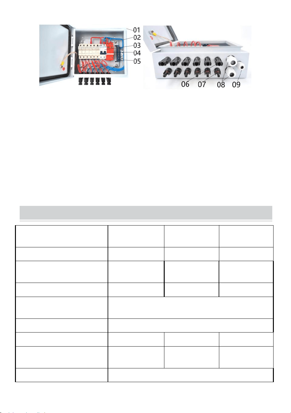
- 5 -
Figuur 2
01---Waterdichte metalen doos
02---4st/6st DC500V zekeringhouder met 10/15A zekering
03--- 63A/ 125A 2P DC500V MCB
04--- SU6-40KA 2P DC500V SPD
05---Neutrale balk
06---4st/6st Zonne-vrouwelijke connector
07---4st/6st Zonne-mannelijke connector
08---2 stuks Uitgang PG16 Kabelwartel
09---Aarding PG9 Kabelwartel
Production Specification
Model
SP-HL-S252310
-15A
SP-HL-S252810
-10A
SP-HL-S252810
-15A
PV-array-invoernummers
4
6
6
Maximale stroom van een
enkele PV-array
1 5A
10A
15A
Enkele PV-array-zekering
1 5A
10A
15A
Enkele PV-array-draadmaat
2,5mm2
Uitvoernummers
1
Maximale uitgangsstroom
6 0A
6 0 Een
90A
Uitgangsdraadmaat
10mm2
1 0mm2
1 6mm2
Maximale uitgangsspanning
500 V DC
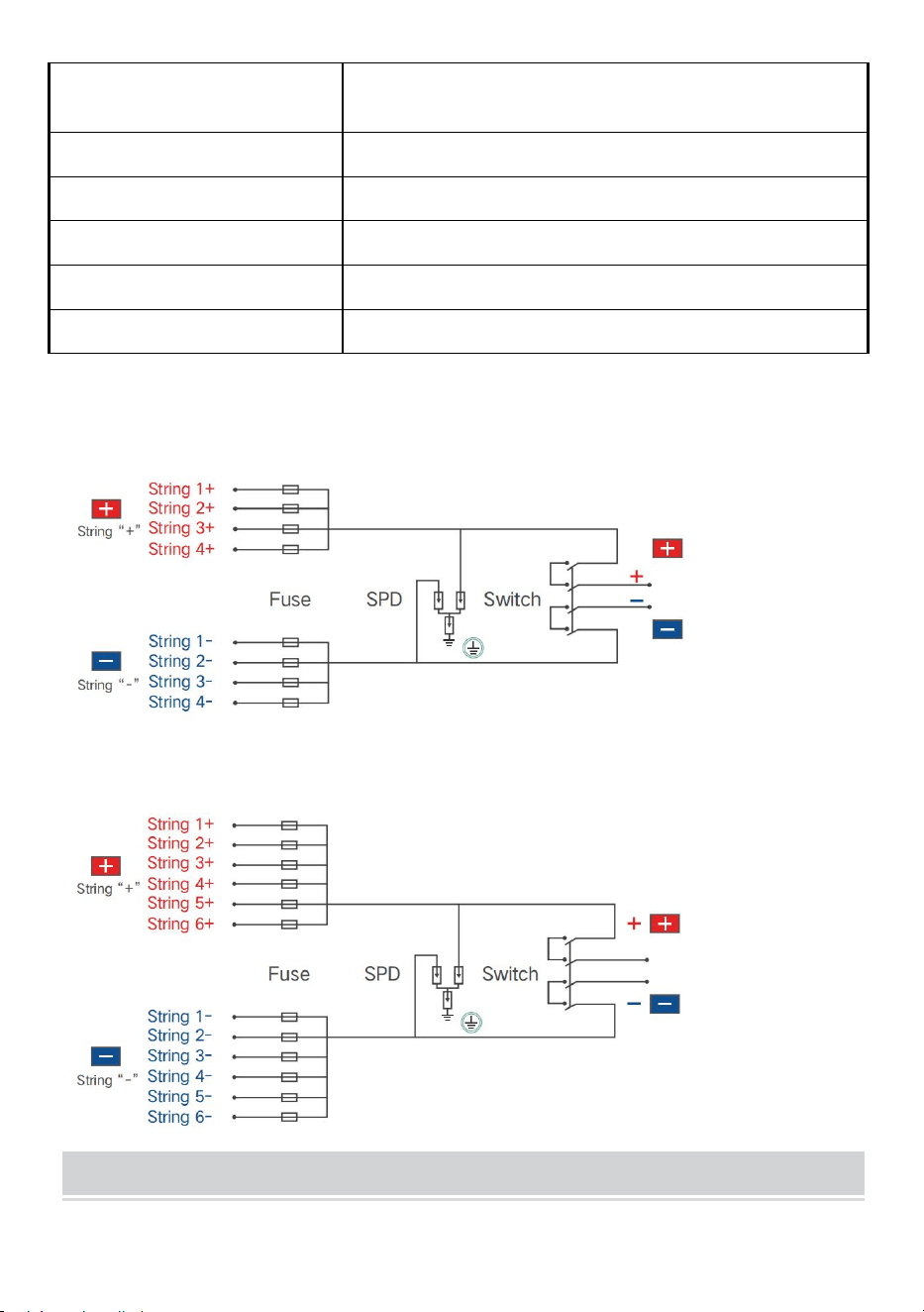
- 6 -
DC-uitgangsstroomonderbre
ker
Ja
Beschermingsniveau
IP-adres 6 6
Temperatuurbereik
- 30℃ ~ +60℃
Koelende manier
Natuurlijk koeling
SPD-beveiliging
Ja
Afmeting aardingsdraad
≥ 2,5mm²
SP-HL-S252310-15A Bedradingsschema van de PV-combinerbox met 4
ingangen en 1 uitgang als volgt:
SP-HL-S252810-10A en SP-HL-S252810-15A Bedradingsschema van de
PV-combinerbox met 6 ingangen en 1 uitgang als volgt:
PV Combiner Box Assembly Process
31.Lijst met accessoires:
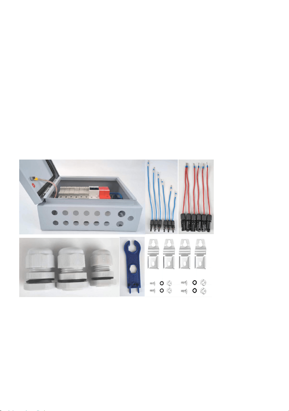
- 7 -
(49)half afgewerkte PV-combinerbox---1st;
(50)Ingang - MC4 mannelijke connector met kabel ---- 4 stuks (voor 4-weg
PV-combinerbox) / 6 stuks (voor 6-weg PV-combinerbox); Tips: elke kabel
heeft een andere lengte, er zit een nummerlabel op elke kabel, let op om
onderscheid te maken.
(51)Input+ MC4 vrouwelijke connector met kabel ---- 4 stuks (voor 4-weg
PV-combinerbox)/6 stuks (voor 6-weg PV-combinerbox); Tips: elke kabel
heeft dezelfde lengte.
(52)Uitgang+ PG13.5 kabelwartel--1st;
(53)Uitgang - PG13.5 kabelwartel - 1 st.;
(54)Aardingskabelwartel PG9--1st;
(55)MC4-gereedschap---1st;
(56)Wandmontagebeugels in zak---1 set;
32.Voorbereidende werkzaamheden
(31)Losse invoer- MC4 vrouwelijke connector ' s montagemoer;
(32)Losse montagemoer van de Input+ MC4 vrouwelijke connector;
(33)Losse 3 stuks kabelwartels ' montagemoer;
(34)van het aansluitblok , zorg ervoor dat het volgende bedradingsproces
eenvoudig te repareren is;
(35)Losse zekeringhouders ' ingang bevestigingsschroeven, zorg ervoor
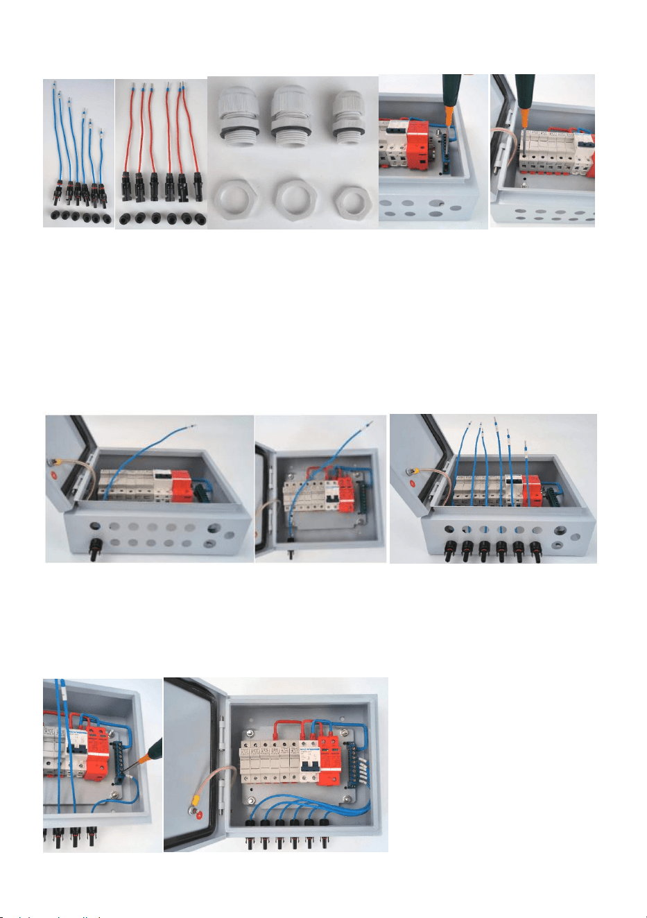
- 8 -
dat het volgende bedradingsproces gemakkelijk te repareren is;
33.Bedrading Ingang - MC4 mannelijke connector met kabel
(25)Montage kabel nr. 1 op de afbeelding 8 toont de positie, bevestig met
een moer;
(26)Monteer de overige kabels op de positie die op afbeelding 9 is
aangegeven en zet ze vast met een moer. De kabelnummers van links
naar rechts zijn: nr. 1-nr. 6;
(27)Bedrading nr. 6 kabel met aansluitblok positie nr. 1;
(28)Het bedraden van de rest van de kabels gebeurt volgens het (3)
proces, stap voor stap. De uiteindelijke status is zoals weergegeven in de
volgende afbeelding.
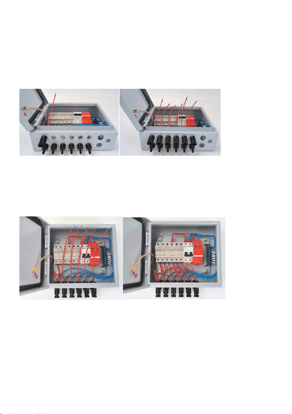
- 9 -
34.Bedrading Input+ MC4 vrouwelijke connector met kabel
(25)Montage kabel nr. 1 op de in afbeelding 12 getoonde positie,
vastzetten met moer;
(26)Monteer de overige kabels op de positie die op afbeelding 13 is
aangegeven en zet ze vast met een moer.
(27)Bedrading kabel nr. 1 met zekeringhouder nr. 1, bevestig de schroef
van de zekeringhouder;
(28)Het bedraden van de rest van de kabels gebeurt volgens het (3)
proces, stap voor stap. De uiteindelijke status is zoals weergegeven in de
volgende afbeelding.
35.Montage van uitgangskabelwartels en aardingskabelwartel.
(25)Montage van 2 stuks PG13.5 kabelwartels op 2 gemarkeerde posities;
(26)Montage van 1 PG9 kabelwartel op de gemarkeerde positie, de
uiteindelijke status is zoals op de afbeelding te zien is
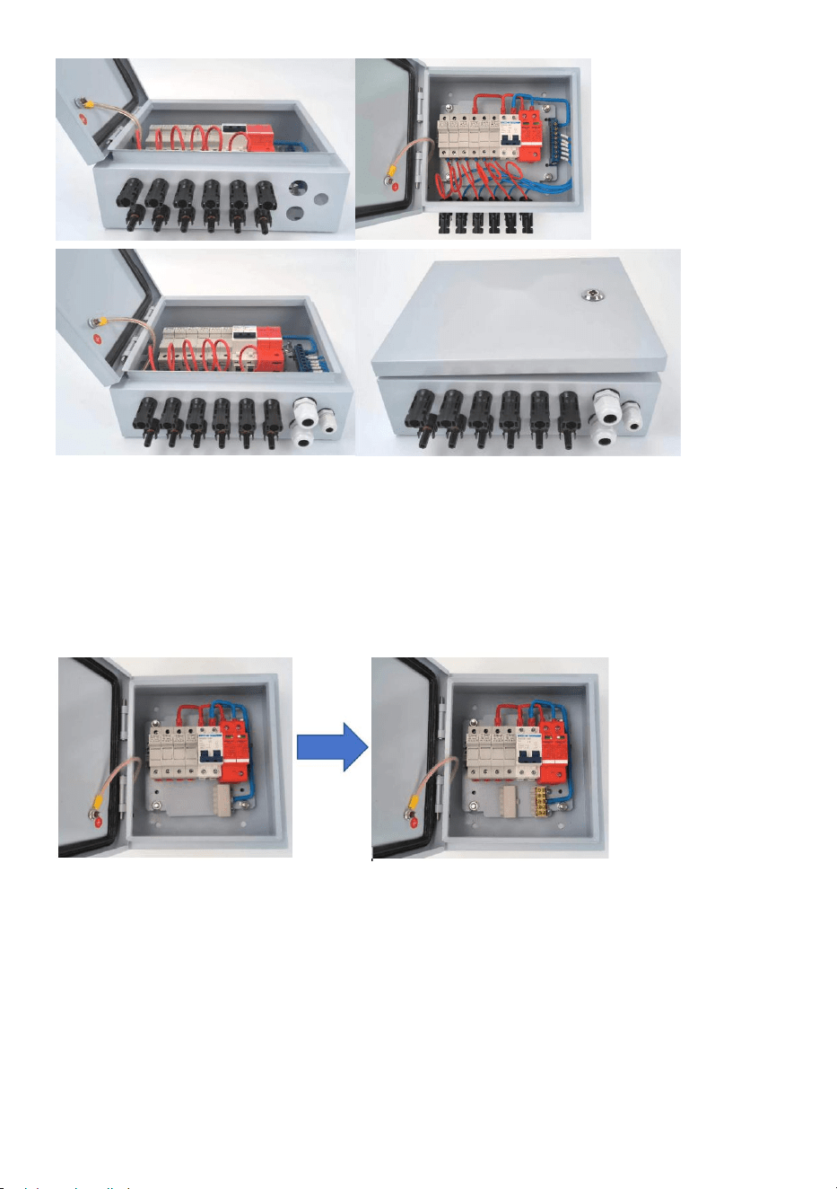
- 10 -
Tips: voor een 4-weg PV-combinerbox zijn hier enkele verschillende
stappen voor het bedraden van de invoer - MC4 mannelijke connector met
kabel vergeleken met de 6-weg PV-combinerbox. De rest van het proces
blijft hetzelfde.
(7) van het aansluitblok als volgt:
(2)Monteer 4 stuks Input-MC4 mannelijke connector met kabel en bevestig
met moer zoals hierboven beschreven;
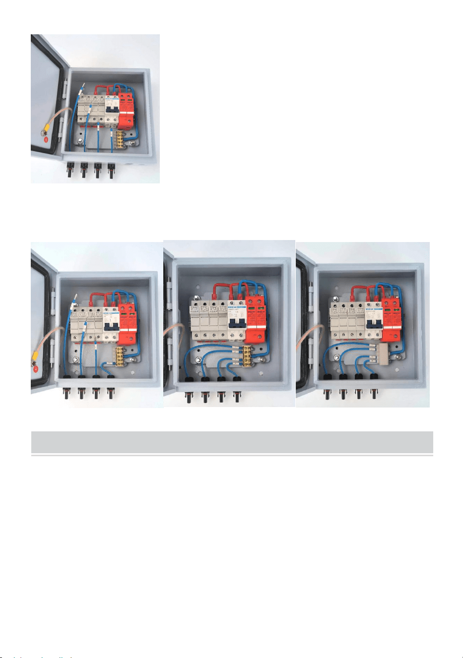
- 11 -
(27)Bedrading nr. 4 kabel met aansluitblok positie nr. 1;
(28)Sluit de rest van de kabels aan volgens het (3) proces, stap voor stap.
Sluit het deksel van het aansluitblok. De uiteindelijke status is als volgt.
Installation & Use
Installatie: Met bijpassende schroeven worden 4 bevestigingsgespen op
de 4 gaten aan de achterkant van de doos bevestigd. Gebruikers kunnen
de juiste positie selecteren om de combinerbox op de muur of het paneel
te monteren.
Snel verbinding
(19)Om te verbeteren de verbinding van snelheid En gemak , gebruik
sleutel naar open de deur van de combinerbox, de ingangsdraad van de
fotovoltaïsche array is aangesloten op de overeenkomstige terminal ,
- 12 -
betalen aandacht naar de fotovoltaïsch reeks invoer lijn van het positieve
En negatief polariteit verbinding .
(20)De combineerder is een onafhankelijke een set van fotovoltaïsch reeks
invoer / uitvoer ontwerp , door redelijk fotovoltaïsch reeks
ingangsverbinding , uitvoer stroom zal een zijn manier , naar
overeenkomst de ene manier onafhankelijk invoer regelaar is gebruikt .
(21)Wanneer gebruikers verbinding systeem , alstublieft maken Zeker
Dat alle de lijnen en uitrusting is betrouwbaar .
Overstroom bescherming
Wanneer de pv module invoer huidig is te groot , de samensmelten
zullen pauze voor bescherming ; In Bovendien kan een
miniatuurstroomonderbreker ook voorkomen dat het systeem stroom
verliest is te groot , hebben overstroom bescherming functie.
WAARSCHUWING !
Het is strikt verboden naar werk in aanraken
zekering , inspectie of vervanging is vereist voor de
samensmelten zullen gelijkstroom
stroomonderbreker uit; Moet vervangen worden
door het originele model van dezelfde grootte
samensmelten .
Overspanning bescherming n
Wanneer de pv module invoer spanning is hoog , de miniatuur circuit
breker zal automatisch loskoppelen , hebben overspanning bescherming
functie .
Appendix

- 13 -
Kwaliteitsborging
Deze productkwaliteitsborgingsperiode bedraagt 1 jaar, tenzij anders
bepaald in de contractperiode van het contract.
Bewijs
Producten in de kwaliteitsborgingsperiode vereisen klanten om de
producten te kopen tonen de factuur en datum. Tegelijkertijd moet het
product van het handelsmerk duidelijk zichtbaar zijn, of het recht hebben
om geen kwaliteitsborging te zijn.
In de volgende situatie heeft dit bedrijf het recht om geen
kwaliteitsborging uit te voeren:
1. Door de mens veroorzaakte schade aan de apparatuur
2. Verkeerde installatie en gebruik
3. Bij gebruik van de maximale limietparameters die verder gaan dan de
apparatuurvereisten ;
4. Abnormale schade aan de natuurlijke omgeving ;
5. Verder zijn er in deze handleiding zeer slechte gebruiksomstandigheden
opgenomen;
6. Buiten de relevante internationale normen die zijn gespecificeerd in de
installatie en het gebruik van het bereik .
Adres: Baoshanqu Shuangchenglu 803long 11hao 1602A-1609shi
Shanghai
Geïmporteerd naar AUS: SIHAO PTY LTD, 1 ROKEVA
STREETEASTWOOD NSW 2122 Australië
Geïmporteerd naar de VS: Sanven Technology Ltd., Suite 250, 9166
Anaheim Place, Rancho Cucamonga, CA 91730

- 14 -
REP
EC
SHUNSHUN GmbH
Römeräcker 9 Z2021, 76351
Linkenheim-Hochstetten, Germany
REP
UK
Pooledas Group Ltd
Unit 5 Albert Edward House, The
Pavilions Preston, United Kingdom
Gemaakt in China


Teknisk Support och e-garanticertifikat
www.vevor.com/support
PV COMBINER BOX
M odel : SP-HL-S252310-15A
SP-HL-S252810-10A
SP-HL-S252810-15A
We continue to be committed to provide you tools with competitive price.
"Save Half", "Half Price" or any other similar expressions used by us only represents an
estimate of savings you might benefit from buying certain tools with us compared to the major
top brands and does not necessarily mean to cover all categories of tools offered by us. You
are kindly reminded to verify carefully when you are placing an order with us if you are
actually saving half in comparison with the top major brands.


- 1 -
M odel : SP-HL-S252310-15A / SP-HL-S252810-10A /
SP-HL-S252810-15A
Have product questions? Need technical support? Please feel free to
contact us:
Technical Support and E-Warranty Certificate
www.vevor.com/support
NEED HELP? CONTACT US!
PV COMBINER BOX
- 2 -
This is the original instruction, please read all manual instructions
carefully before operating. VEVOR reserves a clear interpretation of our
user manual. The appearance of the product shall be subject to the
product you received. Please forgive us that we won't inform you again if
there are any technology or software updates on our product.
Varning - För att minska risken för skada måste användaren
läsa instruktionerna noggrant.
Denna enhet uppfyller del 15 av FCC-reglerna. Driften är
föremål för följande två villkor: (1) Den här enheten får inte
orsaka skadliga störningar och (2) den här enheten måste
acceptera alla mottagna störningar, inklusive störningar som
kan orsaka oönskad funktion.
Denna produkt omfattas av bestämmelserna i det europeiska
direktivet 2012/19/EC. Symbolen som visar en soptunna
korsad anger att produkten kräver separat sophämtning i EU.
Detta gäller för produkten och alla tillbehör märkta med denna
symbol. Produkter märkta som sådana får inte slängas
tillsammans med vanligt hushållsavfall, utan måste lämnas till
en insamlingsplats för återvinning av elektriska och
elektroniska apparater
Identification and Description
För att bättre använda produkten, läs följande instruktioner symbol:
VARNING !
Denna symbolidentifiering för informell användning kan
vara farlig för användarna eller orsaka betydande
hårdvaruskador.
- 3 -
Installation före användning, läs denna manual.
VARNING !
All drift och linjeanslutning frågar professionell person
till drift.
VARNING !
Var uppmärksam på personlig säkerhet och
utrustningssäkerhet.
VARNING!
Observera att fotovoltaisk array-ingång av positiv och
negativ polaritet och den totala utsignalen av den
positiva och negativa polariteten.
VARNING !
Installation eller anslutning pv moduler , observera pv
moduler hög spänning , undvika producera chock fara .
VARNING !
Se till att anslutningen av fäste, för användaren att
använda felaktig eller kabeldragning förlust orsakad av
instabil, vevor företag inte åtar sig något ansvar.
Product Introduction
Fotovoltaiskt kraftgenereringssystem, för att minska solcellsmodulen och
växelriktaren mellan anslutningskablarna, bekvämt underhåll, minska
förlusten och förbättra produktens säkerhet och tillförlitlighet, kräver i
allmänhet i solcellsmodulen och växelriktaren läggs till mellan
sammanflödesanordningen.
Fotovoltaisk kopplingsdosa förutom att ha funktionen som pv-buss
utomhus och samtidigt också ha en strömmotattack, överströmsskydd,
överspänningsskydd, åskskydd och en rad perfekta skyddsfunktioner.
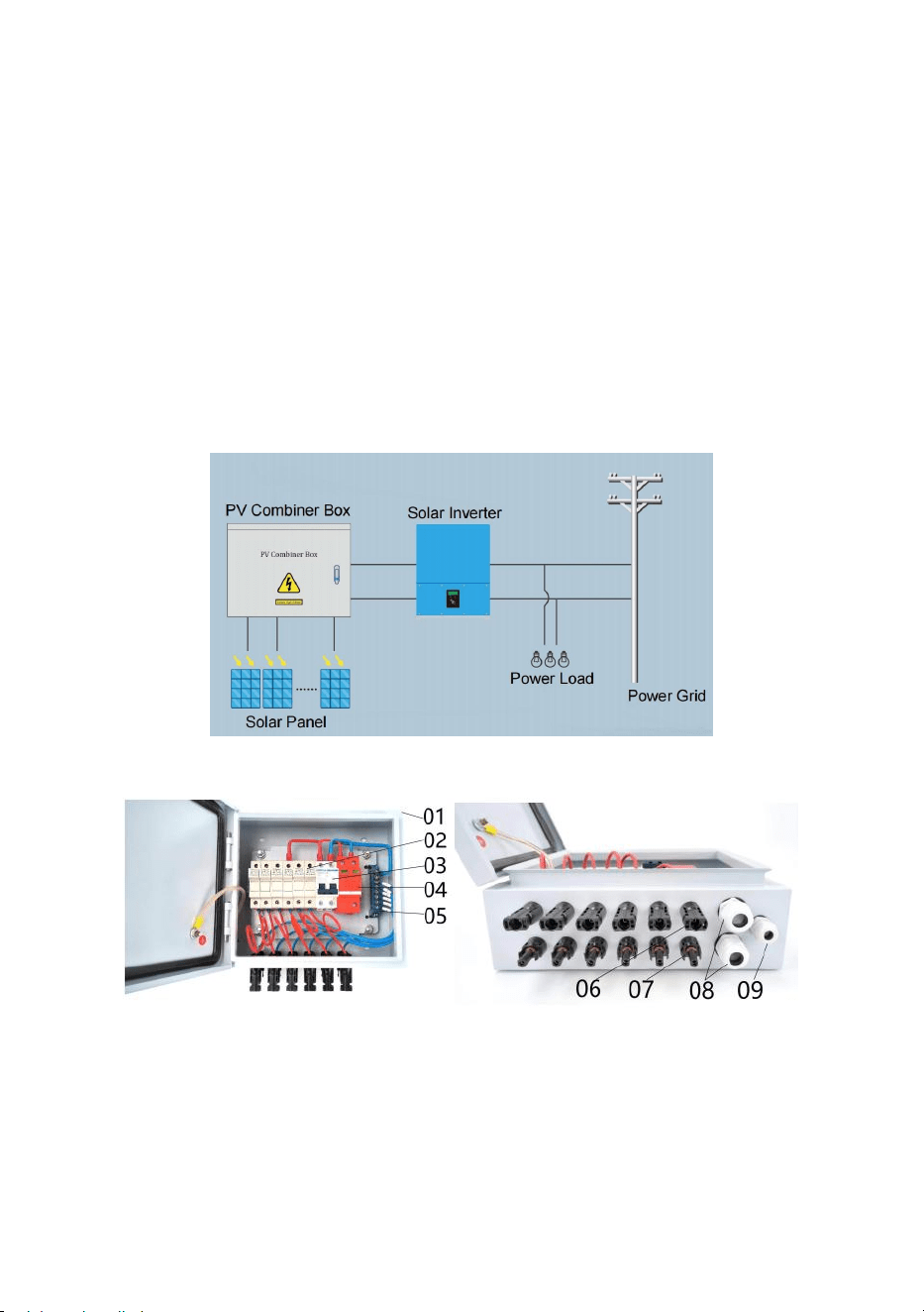
- 4 -
Detta företag producerar solcellsboxen med ovanstående olika
funktionskrav, och fotovoltaiska (PV) nät, från nätverkstyp växelriktare som
stöder användningen kan bilda en komplett uppsättning solcellslösningar
för kraftgenerering.
Välj fotovoltaisk kopplingsbox, användaren kan enligt back-end inverterns
inspänningsområde, uteffektstorlek, ett visst antal specifikationer för
samma pv-modulserie, parallell sammansättning pv-modulserien
koordinatåtkomst fotovoltaisk kopplingsdosa (se figur 1) buss, och sedan
efter effektbrytarkontroll och åskskyddsanordningsskydd efter utgång för
användning av nivåväxelriktare.
Figur 2 visade relaterade delar och dess specifikation.
Bild 1
Figur 2
01---Vattentät metalllåda
02---4st/6st DC500V Säkringshållare med 10/15A säkring
03--- 63A/ 125A 2P DC500V MCB
04--- SU6-40KA 2P DC500V SPD
05---Neutral Bar
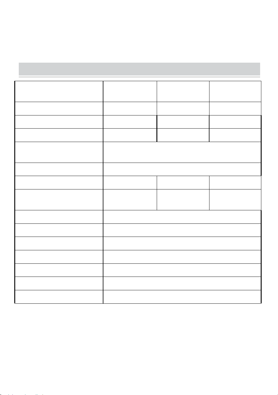
- 5 -
06---4st/6st Solar honkontakt
07---4st/6st Solar hankontakt
08---2st Utgång PG16 Kabelgenomföring
09---Earthing PG9 kabelgenomföring
Production Specification
Modell
SP-HL-S252310
-15A
SP-HL-S252810
-10A
SP-HL-S252810
-15A
PV-matris ingångsnummer
4
6
6
Max enskild PV-matrisström
15A
10A
15A
Enkel PV-matris säkring
15A
10A
15A
Enkel PV-matris trådstorlek
2,5 mm
2
Utdatanummer
1
Max utström
60A
6 0 A
90A
Utgångskabelstorlek
10 mm
2
1 0 mm
2
1 6 mm
2
Max utspänning
500 VDC
DC-utgångsbrytare
ni s
Skyddsnivå
IP 6 6
Temperaturområde
-30 ℃ ~ +60℃
Svalkande sätt
Naturlig kyl-
SPD-skydd
ni s
Jordtrådsstorlek
≥ 2,5 mm ²
SP-HL-S252310-15A Kopplingsschema för PV-kombinationsbox med 4
ingångar 1 utgång enligt följande:
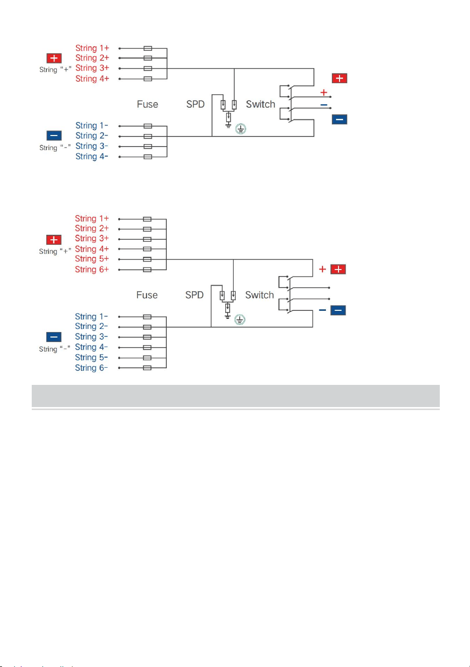
- 6 -
SP-HL-S252810-10A och SP-HL-S252810-15A 6 ingångar 1 utgång PV
combiner box kopplingsschema enligt följande:
PV Combiner Box Assembly Process
36.Tillbehörslista:
(57)halvfärdig PV-kombinationslåda --- 1 st;
(58)Ingång- MC4-hankontakt med kabel----4st (för 4-vägs
PV-kombinationsbox)/6st (för 6-vägs PV-kombinationsbox); Tips: varje
kabel har olika längd, det finns nummeretikett på varje kabel, notera att
särskilja.
(59)Ingång+ MC4 honkontakt med kabel----4st (för 4-vägs
PV-kombinationsbox)/6st (för 6-vägs PV-kombinationsbox); Tips: varje
kabel håller samma längd.
(60)Utgång+ PG13.5 kabelgenomföring--1 st;
(61)Utgång- PG13.5 kabelgenomföring--1 st;
(62)Jordning PG9 kabelgenomföring--1st;
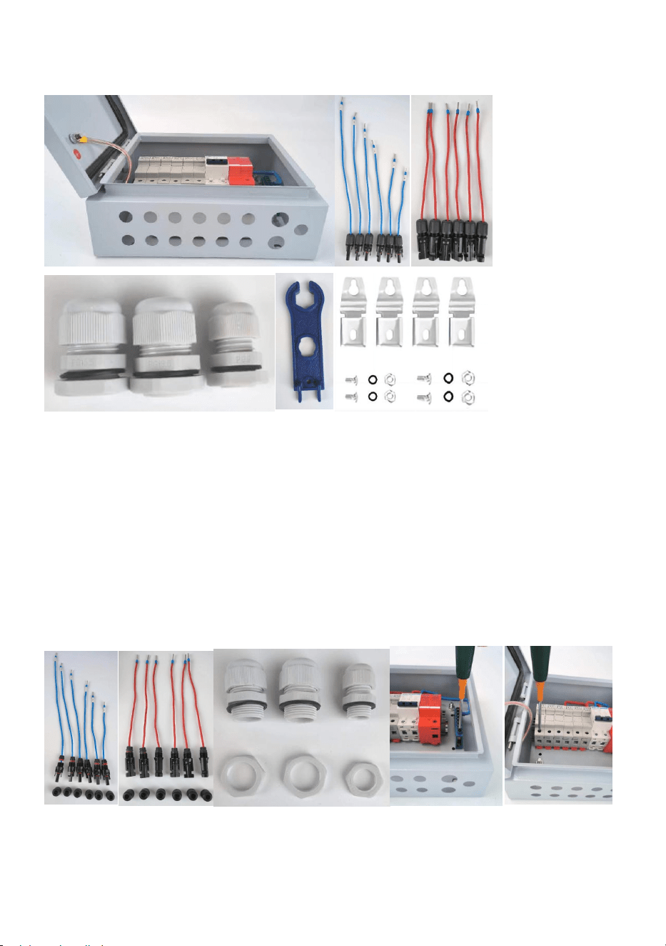
- 7 -
(63)MC4 verktyg --- 1st;
(64)Väggmonteringsfästen väska---1 set;
37.Förarbete
(36)Lös Input- MC4 honkontakts monteringsmutter ;
(37)Lös Input+ MC4 honkontakts monteringsmutter ;
(38)Lösa 3st kabelförskruvningars monteringsmutter ;
(39)Lösa kopplingsplintars ingångar , se till att följande ledningsprocess är
lätt att fixa;
(40)Lösa säkringshållares ingångsfixskruvar, se till att följande
ledningsprocess är lätt att fixa ;
38.Kabelingång - MC4 hankontakt med kabel
(29)Monteringskabel nr 1 på bild 8 visade position, fixera med mutter;
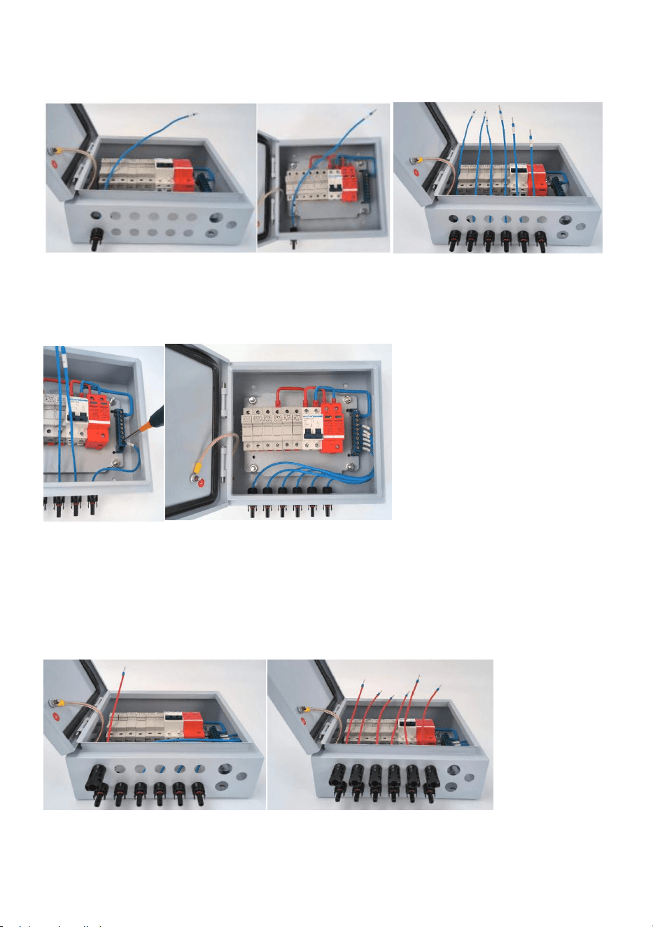
- 8 -
(30)Montering av resten av kablarna på bild 9 visade position, fixera med
mutter. kabelnumret från vänster till höger ska vara nr.1-nr.6;
(31)Kabel nr 6 med kopplingsplints position nr 1;
(32)Koppla in resten av kablarna som (3)process steg för steg,
slutstatusen enligt följande bild visades.
39.Wiring Input+ MC4 honkontakt med kabel
(29)Monteringskabel nr 1 på bild 12 visade position, fixera med mutter;
(30)Montering av resten av kablarna på bild 13 visade position, fixera med
mutter.
(31)Kabel nr 1 med säkringshållare nr 1, fäst skruven för säkringshållaren;
(32)Koppla in resten av kablarna som (3)process steg för steg,
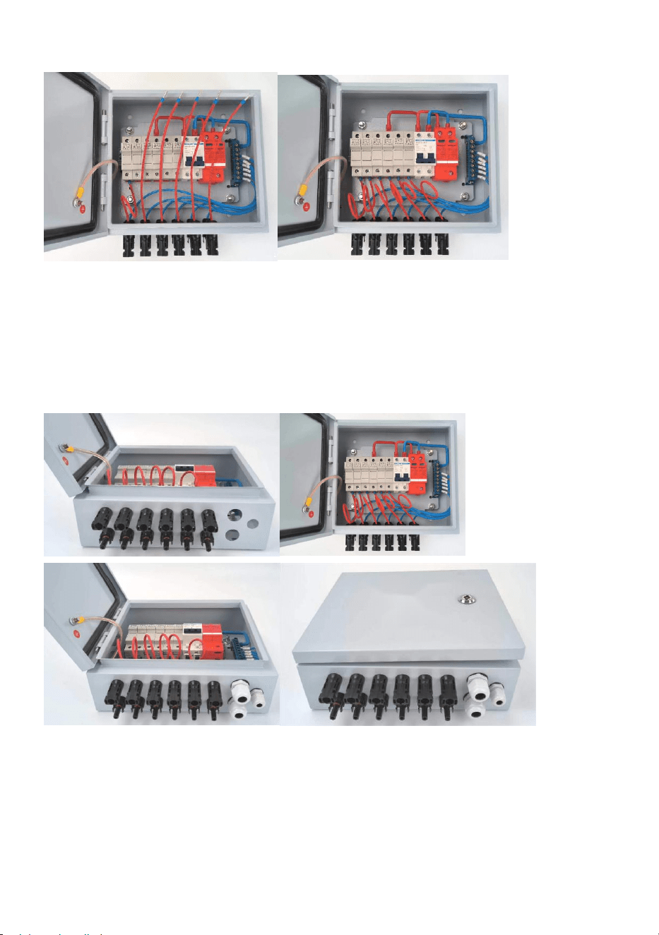
- 9 -
slutstatusen enligt följande bild visades.
40.Montering av utgångskabelförskruvningar och
jordningskabelförskruvningar.
(29)Montering av 2st PG13.5 kabelförskruvningar på markerade 2
positioner;
(30)Montering av 1st PG9 kabelförskruvning på markerad position,
slutstatus enligt följande bild visas
Tips: för 4-vägs PV-kombinationsbox, här har några olika steg för
kabeldragning Input-MC4-hankontakt med kabel jämför med 6-vägs
PV-kombinationsbox. resten av processen behåller samma.
(8) Öppna kopplingsplintens lock enligt följande:
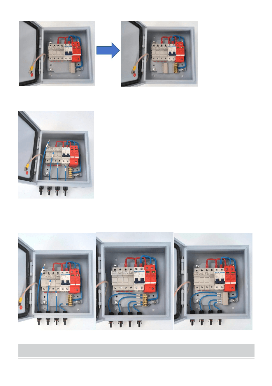
- 10 -
(2)Montering av 4st Input-MC4 hankontakt med kabel och fixera med
mutter på samma sätt som ovanstående process;
(31)Kabelkabel nr 4 med kopplingsplints position nr 1;
(32)Koppla in resten av kablarna som (3)process steg för steg, stäng
plintskyddet, slutstatusen enligt följande visas.
Installation & Use
- 11 -
Installation: Använder matchade skruvar fixerar 4 monteringsspännen på
lådans baksidas 4 hål. Användare kan välja rätt läge och montera
kombinationslådan på väggen eller panelen.
Snabb förbindelse
(22)För att förbättra de förbindelse av snabbhet och bekvämlighet ,
användning nyckel till öppna de dörren till kombinerarboxen, den
fotovoltaiska arrayens ingångskabel ansluten till motsvarande terminal ,
betala uppmärksamhet till de solceller array input linje av det positiva och
negativ polaritet anslutning .
(23)Kombinationen är en oberoende en ställer av solceller array ingång /
utgång design , genom rimlig solceller array ingångsanslutning ,
produktion driva kommer att bli en sätt , till match den ena sätt oberoende
input kontroller är används .
(24)När användare förbindelse system , tack göra säker att alla de rader
och utrustning är pålitlig .
Överström skydd
När de pv modul input nuvarande är för stor , den säkring vilja bryta för
skydd ; I Dessutom kan dvärgbrytare också förhindra att systemet
strömmar är för stor , har överström skydd fungera.
VARNING !
Det är strikt förbjuden till arbete i röra säkring ,
besiktning eller byte är nödvändig före de säkring
vilja dc strömbrytare av; Måste bytas ut mot
originalmodellen av samma storlek säkring .
Överspänning skydd n
När de pv modul input spänning är hög , den miniatyr krets brytare
kommer automatiskt koppla ur , ha överspänning skydd funktion .

- 12 -
Appendix
Kvalitetssäkring
Denna produktkvalitetssäkringsperiod är 1 år, annars föreskrivs i avtalets
avtalsperiod.
Bevis
Produkter i kvalitetssäkringsperioden kräver kunder att köpa
produkterna visar faktura och datum. Samtidigt ska varumärkets produkt
vara väl synlig eller ha rätt att inte vara kvalitetssäkrad.
Följande situation har detta företag rätt att inte till kvalitetssäkring:
1 . Människoskada på utrustningen
2 . Fel installation och användning
3 . Vid användning av maximigränsparametrar utöver utrustningskraven;
4 . Onormala skador på naturen orsakade;
5 . Utöver det i denna manual finns mycket dålig miljödrift;
6 . Utöver de relevanta internationella standarder som specificeras vid
installation och användning av sortimentet .
Adress: Baoshanqu Shuangchenglu 803long 11hao 1602A-1609shi
Shanghai
Importerad till AUS: SIHAO PTY LTD, 1 ROKEVA STREETEASTWOOD
NSW 2122 Australien
Importerad till USA: Sanven Technology Ltd., Suite 250, 9166 Anaheim
Place, Rancho Cucamonga, CA 91730
REP
EC
SHUNSHUN GmbH
Römeräcker 9 Z2021, 76351
Linkenheim-Hochstetten, Germany
REP
UK
Pooledas Group Ltd
Unit 5 Albert Edward House, The
Pavilions Preston, United Kingdom

- 13 -
Tillverkad i Kina


