OPERATOR’S
INSTRUCTION
MANUAL
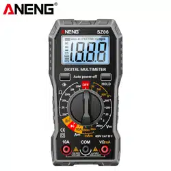
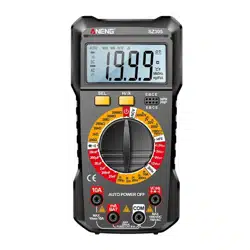
DIGITAL MULTIMETER
READ AND UNDERSTAND THIS MANUAL
BEFORE USING THE INSTRUMENT.
WARNING

-
1
-
INTRODUCTION
This manual provides all safety information, operation
instruction, specifications and maintenance for the meter,
which is compact, hand-held, and battery operated.
This digital multimeter has been designed according to
EN61010-1 oncoming electronic measuring instruments
with an over voltage category (CAT IV 600V,CAT III 1000V)
and Pollution degree 2.
Warning
To avoid possible electric shock or personal injury,
and to avoid possible damage to the Meter or to the
equipment under test, adhere to the following rules:
Before using the meter inspect the case. Do not use
the Meter if it is damaged or the case (or part of the
case) is removed. Look for cracks or missing plastic.
Pay attention to the insulation around the connectors.
Inspect the test leads for damaged insulation or
exposed metal. Check the test leads for continuity.
Do not apply more than the rated voltage, as marked
on the Meter, between the terminals or between any
terminal and grounding.
The rotary switch should be placed in the right position
and no any changeover of range shall be made during
measurement is conducted to prevent damage of the
Meter.
When the Meter working at an effective voltage over
60V in DC or 30V rms in AC, special care should be
taken for there is danger of electric shock.
Use the proper terminals, function, and range for your

-
2
-
measurements.
Do not use or store the Meter in an environment of high
temperature, humidity, explosive, inflammable and
strong magnetic field. The performance of the Meter
may deteriorate after dampened.
When using the test leads, keep your fingers behind
the finger guards.
Disconnect circuit power and discharge all
high-voltage capacitors before testing resistance,
continuity, diodes or hFE.
Replace the batteries as soon as the battery indicator
appears. With a low battery, the Meter might
produce false readings that can lead to electric shock
and personal injury.
Remove the connection between the testing leads and
the circuit being tested, and turn the Meter power off
before opening the Meter case.
When servicing the Meter, use only the same model
number or identical electrical specifications
replacement parts.
The internal circuit of the Meter shall not be altered at
will to avoid damage of the Meter and any accident.
Soft cloth and mild detergent should be used to clean
the surface of the Meter when servicing. No abrasive
and solvent should be used to prevent the surface of
the Meter from corrosion, damage and accident.
The Meter is suitable for indoor use.
Turn the Meter power off when it is not in use and take
out the battery when not using for a long time.

-
3
-
Constantly check the battery as it may leak when it has
been using for some time, replace the battery as soon
as leaking appears. A leaking battery will damage the
Meter.
1. General operations
1.1 Data hold function
This function can hold reading data, when rotate function
switch or repress HOLD button will exit.
a) Press HOLD button, reading hold and icon shown.
b) Press Hold button again, it will exit hold status.
1.2 Battery energy-saving function
If you don’t operate the meter for about 15 minutes, it will
turn off automatically. To turn on it again, just rotate the
function switch or press any button.
1.3 Button introduce
a) SELECT button: Press this button and turn on meter ,it
will disable auto power off function. Press this button to
select desire function, when the function switch on ,
voltage and current range. The select function unit icon
would be display on the LCD.
b) HOLD button: Press this button to hold data, and
repress it to release.
c) HOLD/ button(For 750N only): Press this button to
hold data, and repress it to release. Press and hold more
than 2 seconds will turn on back-light, repeat it to turn off.

-
4
-
2. Operation instruction
2.1 Voltage measurement
1) Connect the black test lead to the “COM” jack and
the red test lead to the “VΩ” jack
2) Set the function switch to desire voltage range,
press SELECT button to select DC or AC function.
3) Connect the test leads across the source or load to
be measured.
4) Read LCD display. The polarity of the red lead
connection will be indicated when making a DC
measurement.
2.2 Current measurement
1) Connect the black test lead to the “COM” jack. If the
current to be measured is less than 200mA, connect
the red test lead to the “mA” jack. If the current is
between 200mA and 10A, connect the red test lead
to the “10A” jack instead.
2) Set the function switch to desired current range.If the
current magnitude to be measured is not known
beforehand, set the function switch to the highest
range position and then reduce it range by range
until satisfactory resolution is obtained.
3) Select DC current measurement or AC current
measurement by the SELECT button.
4) Read the reading on the display. For DC circuit
measurement, the polarity of the red test lead
connection will be indicated as well.

-
5
-
2.3 Resistance measurement
1) Connect the black test lead to the “COM” jack and
the red to the “VΩ” jack.
2) Set the function switch to desire Ω range.
4) Connect the test leads across the load to be
measured.
5) Read the reading on the display.
2.4 Continuity buzzer test
1) Connect the black test lead to the “COM” jack and
the red to the “VΩ” jack.
2) Set the function switch to range.
3) Press the SELECT button to select continuity buzzer
mode, and the symbol “ ” will appear as an
indicator on LCD.
4) Connect the test leads across the load to be
measured.
5) If the circuit resistance is lower than about 30±20Ω,
the built-in buzzer will sound.
2.5 Diode test
1) Connect the black test lead to the “COM” jack and
the red to the “VΩ” jack (Note: The polarity of the red
test lead is positive “+”).
2) Set the function witch to range.
3) Press the SELECT button to select diode test mode,
and the symbol “ ” will appear as an indicator.
4) Connect the red test lead to the anode of the diode

-
6
-
to be tested and the black test lead to the cathode.
5) The meter will show the approximate forward voltage
of the diode. If the connections are reversed, “OL”
will be shown on the display.
2.6 Transistor test
1) Set the function switch to “hFE ” range.
2) Identify whether the transistor is NPN or PNP type
and locate Emitter, Base and Collector lead. Insert
the leads of the transistor to be tested into the
proper holes of the meter test socket.
3) LCD display will show the approximate hFE value.
2.7 Capacitance measurement
1) Connect the black test lead to the “COM” jack and
the red to the “VΩ” jack.
2) Set the function switch to desire “ ”range.
3) Connect test leads across the capacitor under
measure and be sure the polarity of connection is
observed. Note: When the capacitance under measure is
more than 200uF, it needs at least 10 seconds to
make readings stable.
2.8 Battery test
1) Connect the black test lead to the "COM" jack and
the red test lead to the "mA" jack.
2) According to the different type of the battery
(1.5V,3V,9V,12V) to be tested, set the range switch
to the desired BATT range.

-
7
-
3) Connect the test leads to the battery to be tested.
4) Read the reading on the display.The polarity of the
red test lead connection will be indicated.
2.9 Frequency measuring
1) Set the function range switch to the required
frequency range.
2) Connect the BLACK test lead to the “COM” jack and
the RED to the “VΩ” jack.
3) Connect the test leads across the load to be
measured.
4) Read the reading on the display.
3. GENERAL CHARACTERISTICS
Display: 2000 counts LCD with units icon.
Polarity indication: “-” displayed automatically
Over-range indication: Only “OL” displayed
Low battery indication: “ ” displayed
Range select: Manual
Operation temperature: 0°C to 40°C, less than 80%RH
Storage temperature: -10°C to 50°C, less than 85%RH
Battery type : Two 1.5V AAA size batteries
-
8
-
4. SPECIFICATIONS
Accuracy is guarantied for 1 year 23°C±5°C less than
80%RH
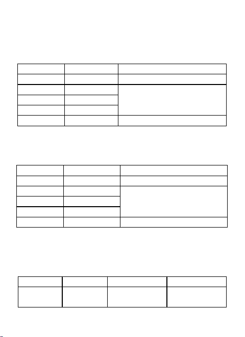
4.1 DC voltage
Range
Resolution
Accuracy
200mV
0.1mV
±(0.5% of rdg + 3dgts)
2V
1mV
±(0.8% of rdg + 5dgts)
20V
10mV
200V
100mV
1000V
1V
±(1.0% of rdg + 5dgts)
Input impedance: 10MΩ
Max. Input voltage: 1000V DC or 750V AC rms
4.2 AC voltage
Range
Resolution
Accuracy
200mV
0.1mV
±(1.2% of rdg + 5dgts)
2V
1mV
±(1.0% of rdg + 5dgts)
20V
10mV
200V
100mV
750V
1V
±(1.2% of rdg + 5dgts)
Input impedance: 10MΩ
Frequency range: 40Hz ~ 400Hz
Response: Average, calibrated in rms of sine wave
Max. Input voltage: 750V AC rms
4.3 Transistor hFE test
Range
hFE
Test Current
Test Voltage
PNP &
NPN
0~1000
Ib≈10µA
Vce≈2.8V
-
9
-
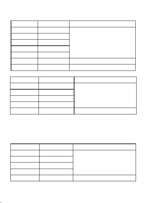
4.4 Resistance
Range
Resolution
Accuracy
200Ω
0.1Ω
±(1.0% of rdg + 5dgts)
2KΩ
1Ω
20KΩ
10Ω
200KΩ
100Ω
2MΩ
1KΩ
20MΩ
10KΩ
±(1.5% of rdg + 10dgts)
200MΩ
100KΩ
±(5.0% of rdg + 10dgts)
4.5 DC current
Range
Resolution
Accuracy
200µA
0.1µA
±(1.5% of rdg + 8dgts)
2mA
1µA
20mA
10µA
200mA
100µA
10A
10mA
±(2.0% of rdg + 10dgts)
Overload Protection: mA: F0.5A/250V fuse; 10A: unfused
Voltage Drop: 200mV
For measurements>5A:duration<10 seconds, interval >1
minutes.
4.6 AC current
Range
Resolution
Accuracy
200µA
0.1µA
±(2.0% of rdg + 5dgts)
2mA
1µA
20mA
10µA
200mA
100µA
10A
10mA
±(2.5% of rdg + 10dgts)
Overload Protection: mA: F0.5A/250V fuse; 10A: unfused
-
10
-
Voltage Drop: 200mV
Frequency Range: 40Hz ~ 400Hz
Response: Average, calibrated in rms of sine wave
For measurements>5A:duration<10 seconds, interval >1
minutes.
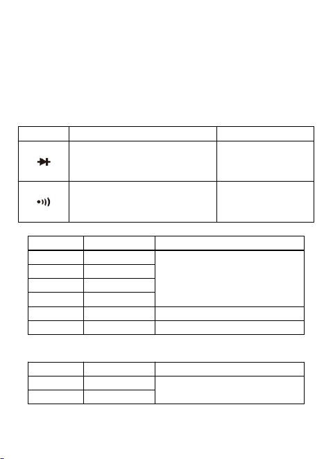
4.7 Diode and continuity
Range
Introduction
Remark
The approximate forward
voltage drop will be
displayed
Open circuit
voltage: about
1.5V
The built-in buzzer will
sound if the resistance is
less than about 30±20Ω.
Open circuit
voltage: about
0.5V
4.8 Capacitance
Range
Resolution
Accuracy
20nF
10pF
±(4.0% of rdg + 10dgts)
200nF
100pF
2µF
1nF
20µF
10nF
200µF
100nF
±(4.5% of rdg + 15dgts)
20mF
10µF
±(6.0% of rdg + 20dgts)
4.9 Frequency
Range
Resolution
Accuracy
200Hz
0.1Hz
±(1.5% of rdg + 8dgts)
2KHz
1Hz

-
11
-
5. Maintenance
This section provides basic maintenance information,
including instructions for replacing the fuse and battery.
Do not attempt to repair this instrument unless you are an
experienced repairman with relevant calibration,
performance testing, and repair information.
5.1 General maintenance
Regularly use a damp cloth and a small amount of
detergent to clean the instrument casing. Do not use
abrasive or chemical solvents. If the input socket is dirty or
damp, it may affect the reading.
To clean the input socket:
a) Turn off the meter and remove all test leads from the
input socket.
b) Remove all dirt from the socket.
c) Dip a new cotton ball with a cleaning agent or lubricant.
d) Clean each socket with a cotton ball. Lubricant can
prevent socket contamination related to moisture.
5.2 Replace battery
If the sign “ ” appear on the display, it indicates battery
should be replaced. Remove screws and open the back
case, replace the exhausted battery with new battery.
5.3 Replace fuse
a) Fuse replacement should only be done after the test
leads have been disconnected and power is off.
b) Loosen screws with suitable screwdriver and remove
case bottom.
c) The meter is protected by fuse:F0.5A/250V Fast,
dimensions is Φ5*20mm.