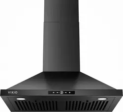
30” and 36”
Vent Hood
Installation
Instructions
BEFORE YOU BEGIN
Read these instructions carefully and completely.
■ IMPORTANT – Save these instructions for
local inspector’s use.
■ IMPORTANT – Observe all governing codes
and ordinances.
■ Note to Installer – Be sure to leave these instructions
with Consumer.
■ Note to Consumer – Keep these instructions for
future reference.
■ Skill level – Installation of this appliance requires a
qualied installer or electrician.
■ Completion time – Approximately 1 to 3 hours
■ Proper installation is the responsibility of the installer.
■ Product failure due to improper installation is not
covered under Warranty.
If you have questions, call GE Appliances at 800.GE.CARES (800.432.2737)
or visit our website at: GEAppliances.com
PVW1030, PVW1036
31-7000240 Rev. 2 08-24
CAUTION
Due to the weight and size of these vent hoods and to reduce the risk of personal injury or
damage to the product, TWO PEOPLE ARE REQUIRED FOR PROPER INSTALLATION.
WARNING
To reduce the risk of fire or electrical shock, do not use this range hood with any external solid-
state speed control device. Any such alteration from original factory wiring could result in damage to the unit and/or
create an electrical safety hazard.
TO REDUCE THE RISK OF FIRE, USE ONLY METAL DUCTWORK.
WARNING
TO REDUCE THE RISK OF FIRE, ELECTRICAL SHOCK OR INJURY TO PERSONS, OBSERVE
THE FOLLOWING:
A. Use this unit only in the manner intended by the manufacturer. If you have any questions, contact the
manufacturer.
B. Before servicing or cleaning the unit, switch the power off at the service panel and lock the service disconnecting
means to prevent the power from being switched on accidentally. When the service disconnecting means cannot
be locked, securely fasten a prominent warning device,such as a tag, to the service panel.
CAUTION
FOR GENERAL VENTILATING USE ONLY. DO NOT USE TO EXHAUST HAZARDOUS
MATERIALS, EXPLOSIVE MATERIALS OR VAPORS.
2 31-7000240 Rev. 2
Safety Information
READ AND SAVE THESE INSTRUCTIONS
WARNING
TO REDUCE THE RISK OF FIRE, ELECTRICAL SHOCK OR INJURY TO PERSONS, OBSERVE
THE FOLLOWING:
■ Installation work and electrical wiring must be done by qualified person(s) in accordance with all applicable codes
and standards, including fire-rated construction.
■
Sufficient air is needed for proper combustion and exhausting of gases through the flue (chimney) of fuel burning
equipment to prevent back-drafting. Follow the heating equipment manufacturer’s guidelines and safety standards,
such as those published by the National Fire Protection Association (NFPA), the American Society for Heating,
Refrigeration and Air Conditioning Engineers (ASHRAE) and the local code authorities. When applicable, install any
makeup (replacement) air system in accordance with local building code requirements. Visit GEAppliances.com for
available makeup air solutions.
■ When cutting or drilling into walls or ceilings, do not damage electrical wiring and other hidden utilities.
■ Ducted systems must always be vented to the outdoors.
■
Local codes vary. Installation of electrical connections and grounding must comply with applicable codes. In the
absence of local codes, the vent should be installed in accordance with National Electrical Code ANSI/NFPA 70-1990
or latest edition.
CAUTION
To reduce risk of fire and to properly exhaust air, be sure to duct air outside—do not vent exhaust
air into spaces within walls or ceilings or into attics, crawl spaces or garages.
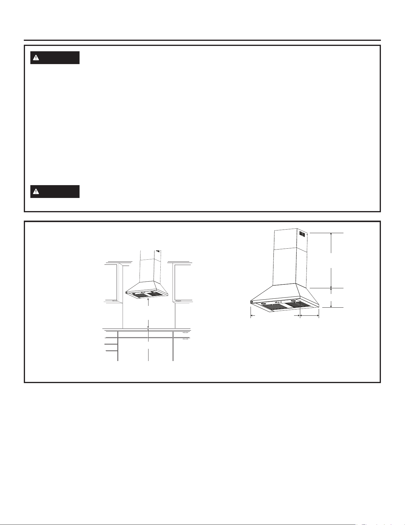
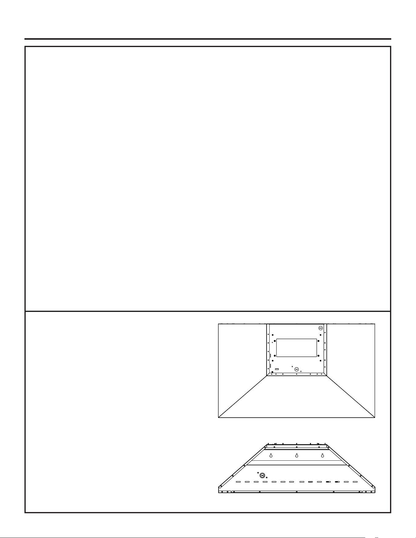
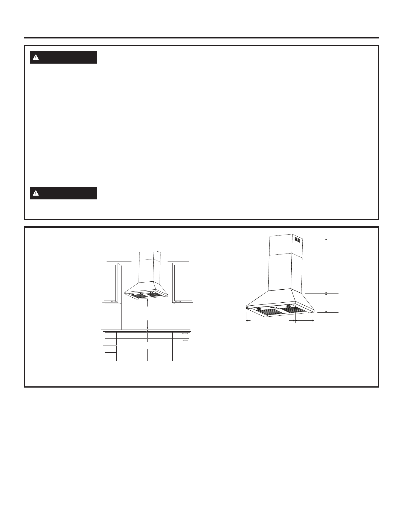
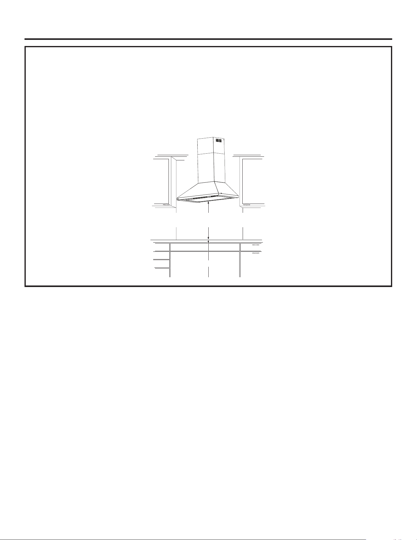
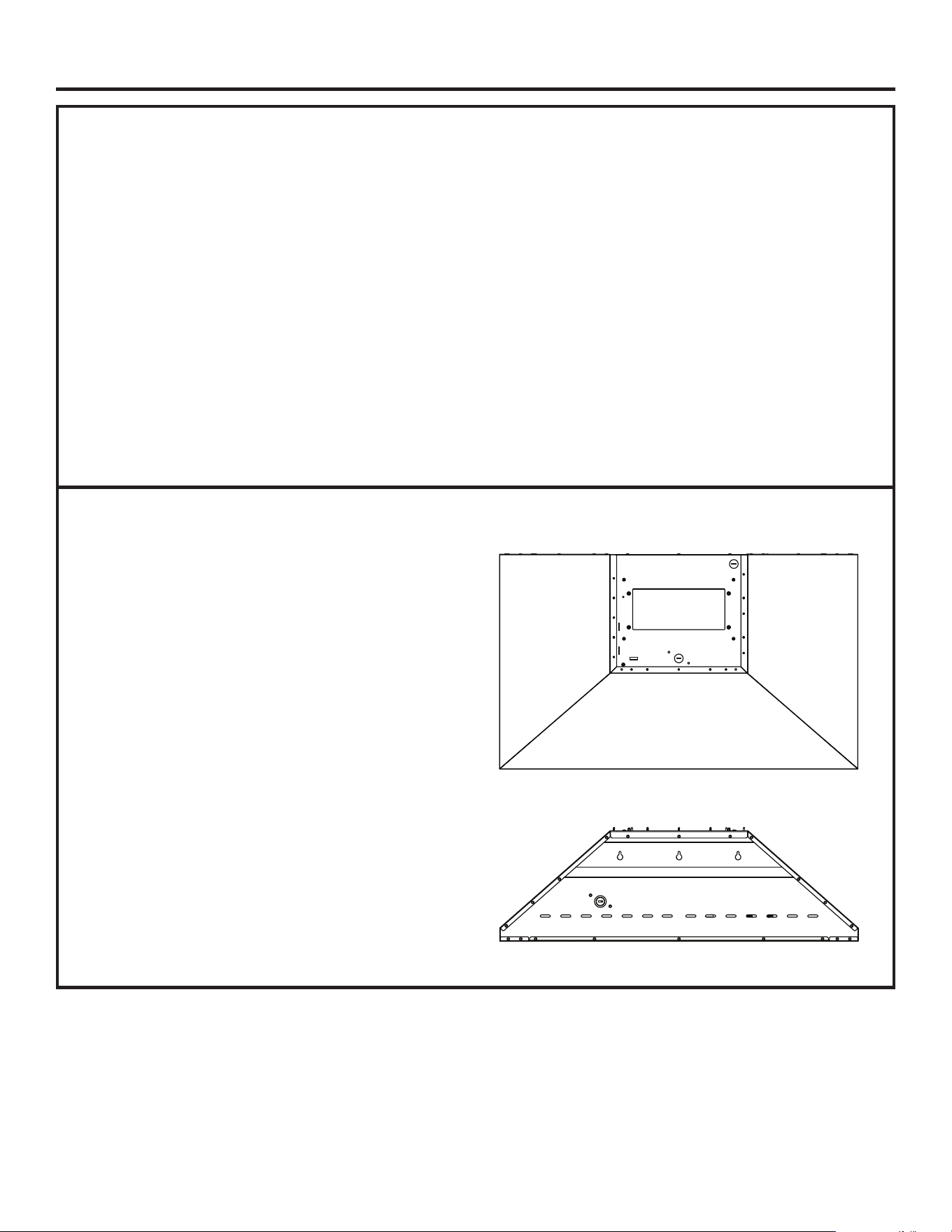
PRODUCT DIMENSIONS AND
CLEARANCES
The vent hood must be
installed 24″ minimum,
and 30″ maximum
above the cooking
surface.
NOTE: Installation
height should be
measured from the
cooking surface to the
lowest part of the hood.
PX8DC1SWSS Duct Cover Accessory
This accessory is available for installations with ceiling
heights above 9’ to 10’ and higher. See the table on
page 8.
The duct cover accessory must be on-site with the hood
at the time of installation.
24″ Minimum
30″ Maximum
36″ Minimum
*Height to
Ceiling
11-1/8”
21-1/2”
30” for PVW1030
36” for PVW1036
31-7000240 Rev. 2 3
Installation Preparation
DUCTWORK PLANNING
■ This hood is designed to be vented vertically
through the ceiling. Use locally supplied elbows to
vent horizontally through the rear wall.
■ Determine the exact location of the vent hood.
■ Plan the route for venting exhaust to the outdoors.
■ Use the shortest and straightest duct route possible.
For satisfactory performance, duct run should
not exceed 150′ equivalent length for any duct
configurations.
■ Refer to “Duct Fittings” chart to compute the
maximum permissible length for duct runs to the
outdoors.
■ Use rigid metal ductwork only.
■ This vent hood must use a 8” round duct.
■ Install the house duct to run horizontally between
ceiling joists or straight up through the roof.
■ Install a wall or roof cap with damper at the exterior
opening. Order the wall or roof cap and any
transition and length of duct needed in advance.
■ When applicable, install any makeup (replacement)
air system in accordance with local building code
requirements. Visit GEAppliances.com for available
makeup air solutions.
WARNING
TO REDUCE THE RISK OF FIRE,
USE ONLY RIGID METAL DUCTWORK.
WALL FRAMING FOR ADEQUATE
SUPPORT
■ This vent hood is heavy. Adequate structural support
must be provided. The hood must be secured to a
vertical stud in the wall. See page 9 or 14.
■ We strongly recommend that the vent hood with
duct cover be on site before final framing and wall
finishing. This will also help to accurately locate the
ductwork and electrical service.
■
Installation will be easier if the vent hood is installed
before the cooktop and countertop are installed.
ADVANCE PLANNING
A duct cover accessory may be required for your hood
installation depending on ceiling height.
4 31-7000240 Rev. 2
Installation Preparation
POWER SUPPLY
IMPORTANT – (Please read carefully)
WARNING
FOR PERSONAL SAFETY, THIS
APPLIANCE MUST BE PROPERLY GROUNDED.
Remove house fuse or open circuit breaker before
beginning installation.
Do not use an extension cord or adapter plug with
this appliance. Follow National Electrical Code or
prevailing local codes and ordinances.
Electrical supply
This vent hood must be supplied with 120V, 60Hz, and
connected to an individual, properly grounded branch
circuit, and protected by a 15- or 20-amp circuit
breaker or time-delay fuse.
■ Wiring must be 2-wire with ground.
■ If the electrical supply does not meet the above
requirements, call a licensed electrician before
proceeding.
■ Route house wiring as close to the installation
location as possible. Wiring can enter from the
ceiling or rear wall. Route additional length from the
ceiling or wall to reach the junction box.
■ Connect the wiring to the house wiring in
accordance with local codes.
Grounding instructions
The grounding conductor must be connected to
a ground metal, permanent wiring system, or an
equipment-grounding terminal or lead on the hood.
WARNING
The improper connection of the
equipment-grounding conductor can result in a risk
of electric shock. Check with a qualified electrician or
service representative if you are in doubt whether the
appliance is properly grounded.
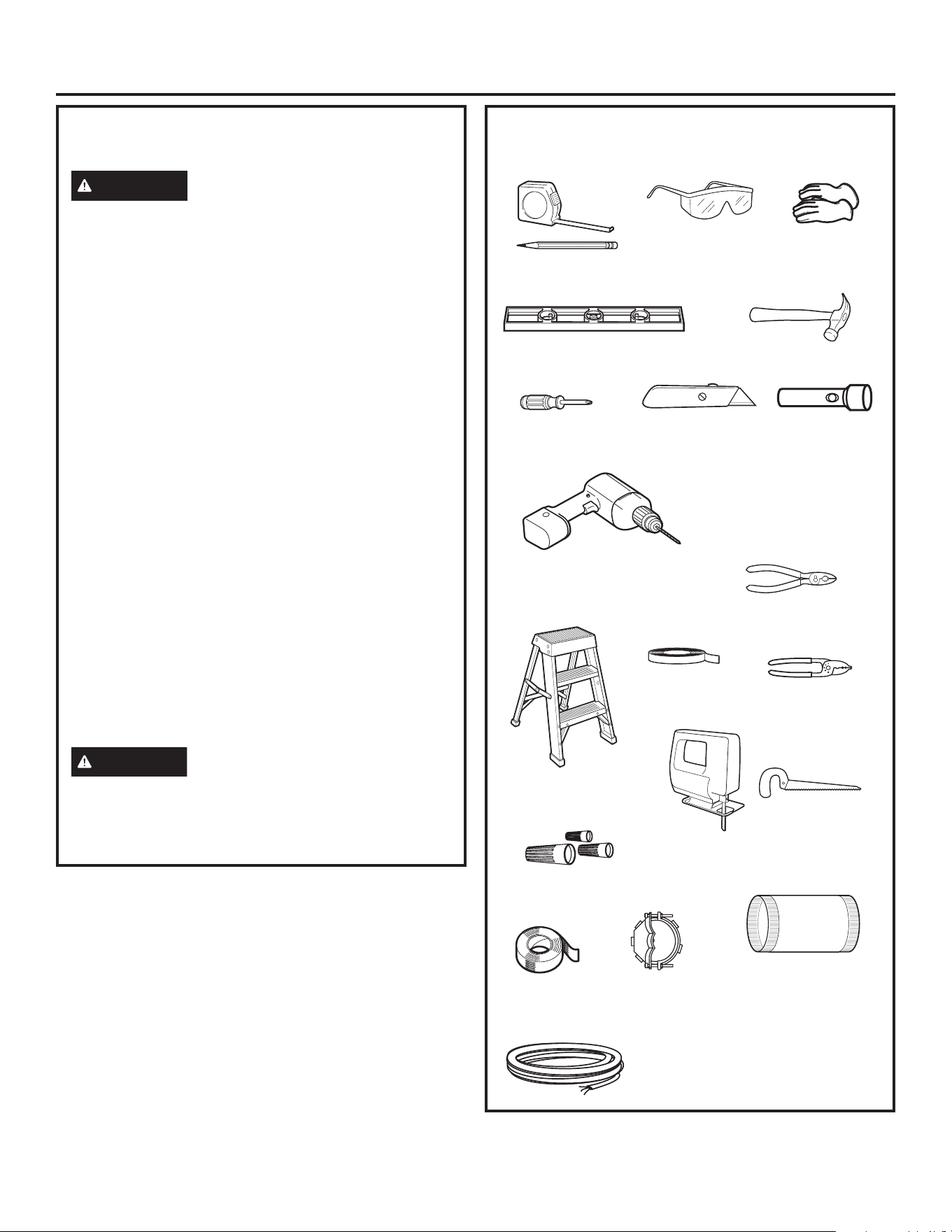
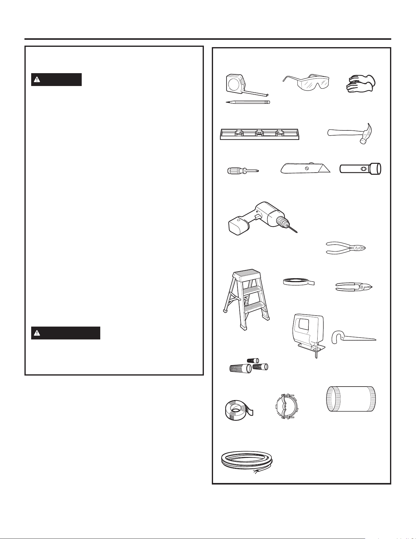
TOOLS AND MATERIALS REQUIRED
(Not Supplied)
Masking tape
Gloves
Utility Knife
Pliers
Wire cutter/stripper
Spirit level
Aluminized
duct tape
Safety glasses
120V 60Hz. 15- or 20-Amp,
2-wire with ground, properly grounded
branch circuit
Electrical Cable
Stepladder
Saber saw or Key Hole saw
Phillips screwdriver
Strain relief for
junction box
Strain Relief I
8″ round metal duct, length
to suit installation
Hammer
Electric drill with 1/8″ bits, #2
Phillips and flat head and T20 torx
6” driver extension
Flashlight
UL-listed wire nuts
Wire Nuts
Pencil and tape
measure
31-7000240 Rev. 2 5
Installation Preparation
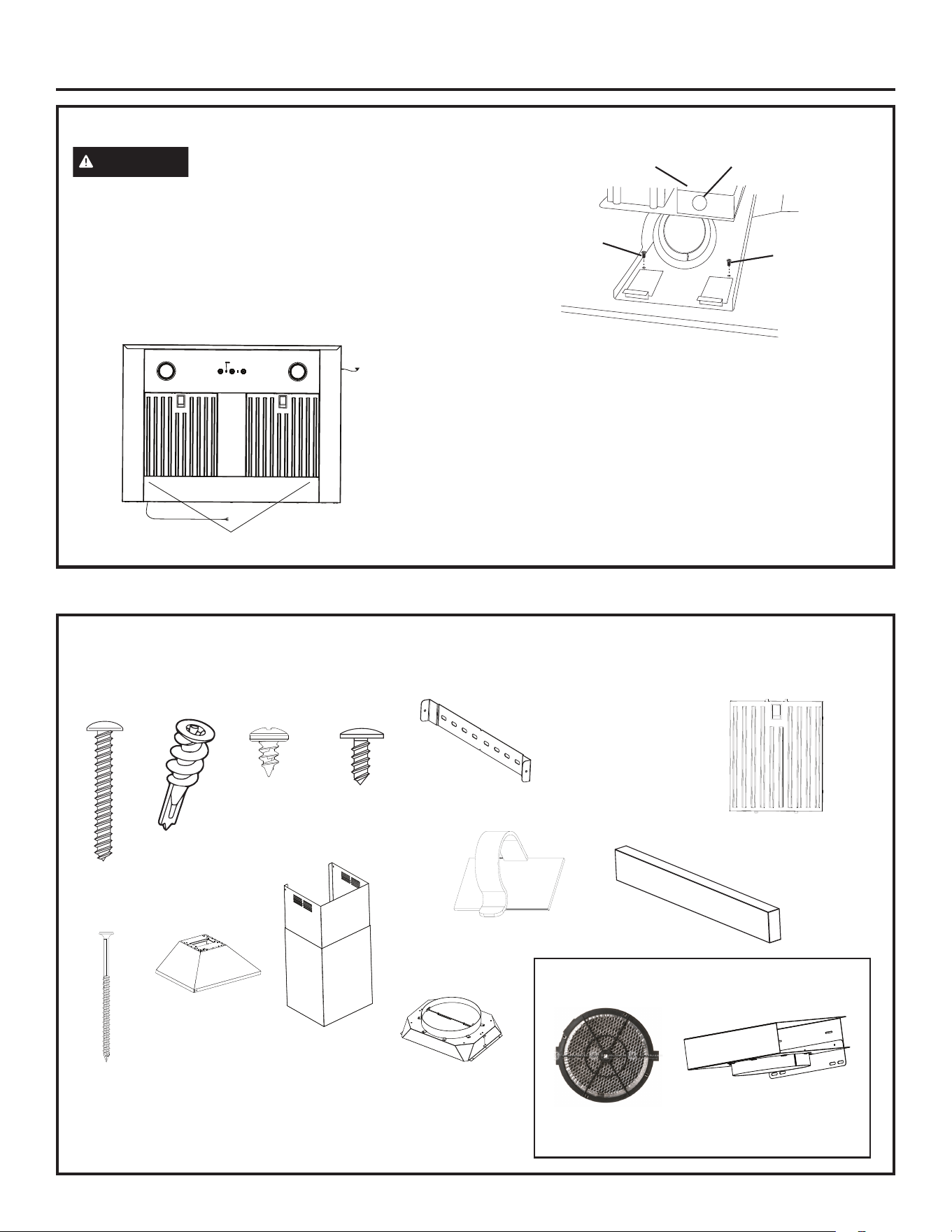
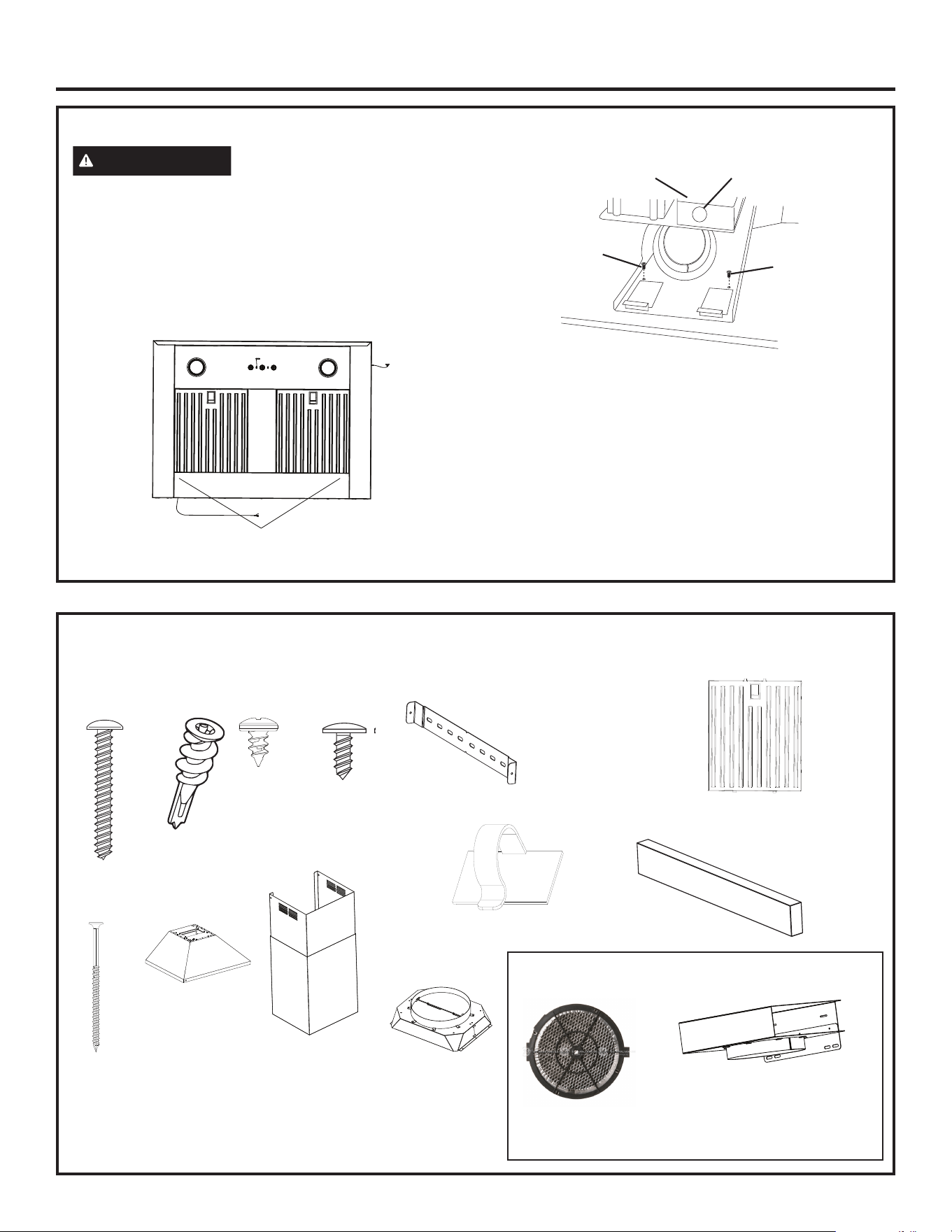
REMOVE THE PACKAGING
CAUTION
Wear gloves to protect against sharp
edges.
■ Remove the duct cover, parts box and foam
packaging.
■ Lift the hood out of the box.
■ Remove and properly discard the plastic wrapping.
■ Remove metal grease filters and side bar packaging.
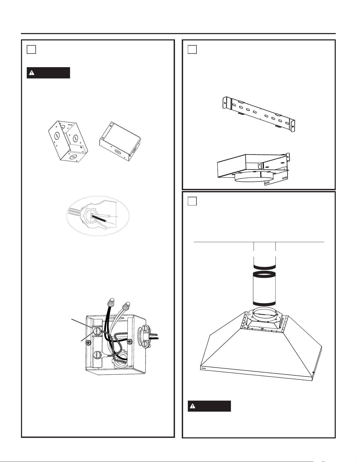
■ Remove junction box cover.
■ Remove knockout from junction box.
■ Install strain relief onto junction box.
Mounting screw
Mounting screw
Mounting
screw
Knockout
Junction box
CHECK INSTALLATION HARDWARE
Locate the hardware accessory box packed with the
hood and check contents.
658Dia37
Nine 2”
wood
screws
Decorative duct
covers
10 Duct
cover
screws
Additional Parts for Recirculation Operation
Optional accessories purchased separately
NOTE: Additional tools, materials and hardware are required to
construct your wall framing support.
2 charcoal filters
(UXCF91)
8 anchors
2 Stainless Steel
Grease Filters (30”)
or 3 Stainless Steel
Grease Filters (36”)
Wood Bar
2 Duct cover
brackets
Recirculation box
(UXCN36)
1 Piece Self Adhesive
Cable Clips
Damper Assembly 8”
6 Damper
screws
Three 3”
Wood Screws
Hood Body

6 31-7000240 Rev. 2
Installation Preparation
DETERMINE INSTALLATION HEIGHT
■ A 10’ ceiling height telescopic duct cover accessory is included to conceal the ductwork running to the ceiling.
8’, 12’, or 14’ ceiling heights can be accommodated with the optional accessories.
■ This hood can be installed for vented or recirculating (36” width model only) operation.
NOTE: Installation height should be measured from the cooking surface to the bottom of the hood.
The vent hood must be installed above the cooking surface 24″ min to 30″ max for electric and 30” min to 36” max
for gas. The hood installation height, from the cooking surface to the bottom of the hood, also depends upon ceiling
height and duct cover limitations.
24” Min / 30” Max (Electric)
30” Min / 36” Max (Electric)
36″ Min
31-7000240 Rev. 2 7
Installation Preparation
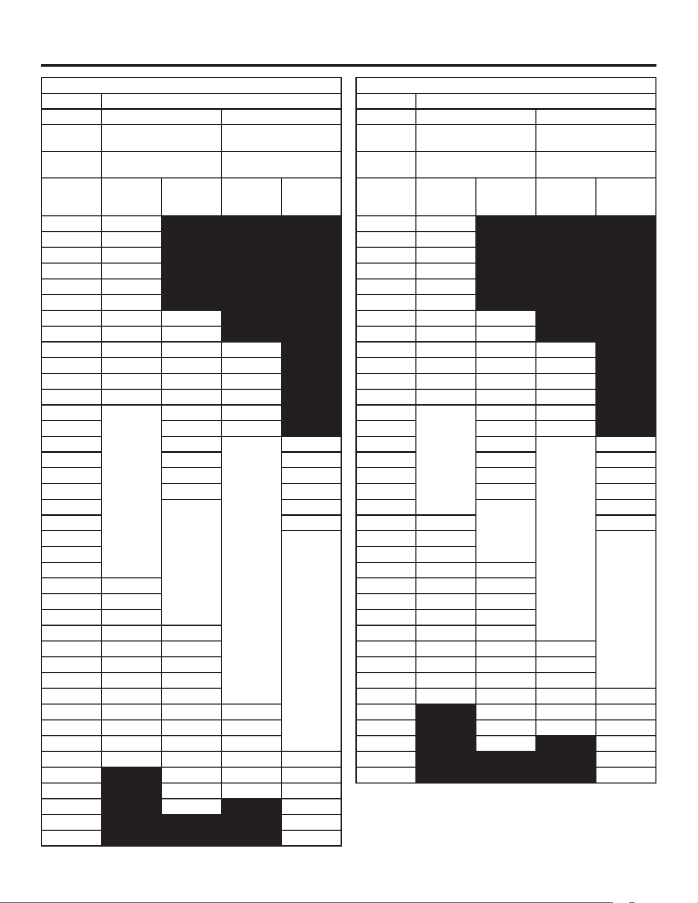
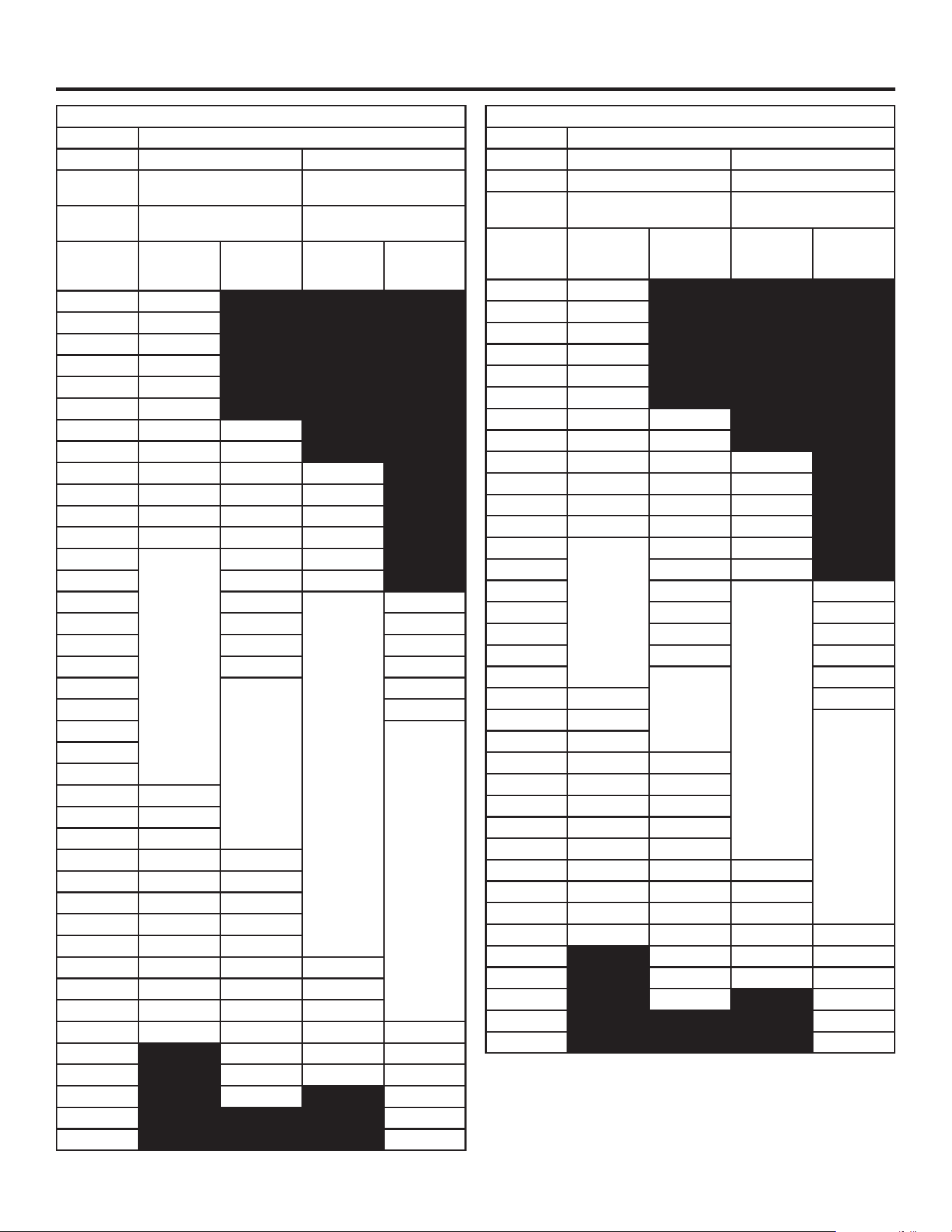
Included Accessory
High Ceiling Duct Cover up to 10 ft
Upper Lower
25.56”H x 13.67”W x
11.83”D
19.50”H x 13.81”W x
11.94”D
Installation over Electric
Range
Installation over Gas
Range
Ceiling
Height (ft./
in.)
Vented
Installation
Height
Recirc
Installation
Height
Vented
Installation
Height
Recirc
Installation
Height
7' 7" 24
7' 8" 24 - 25
7' 9" 24 - 26
7' 10" 24 - 27
7' 11" 24 - 28
8' 0" 24 - 29
8' 1" 24 - 30 24
8' 2" 24 - 31 24 - 25
8' 3" 24 - 32 24 - 26 30
8' 4" 24 - 33 24 - 27 30 - 31
8' 5" 24 - 34 24 - 28 30 - 32
8' 6" 24 - 35 24 - 29 30 - 33
8' 7"
24 - 36
24 - 30 30 - 34
8' 8" 24 - 31 30 - 35
8' 9" 24 - 32
30 - 36
30
8' 10" 24 - 33 30 - 31
8' 11" 24 - 34 30 - 32
9' 0" 24 - 35 30 - 33
9' 1"
24 - 36
30 - 34
9' 2" 30 - 35
9' 3"
30 - 36
9' 4"
9' 5"
9' 6" 25 - 36
9' 7" 26 - 36
9' 8" 27 - 36
9' 9" 28 - 26 25 - 36
9' 10" 29 - 36 26 - 36
9' 11" 30 - 36 27 - 36
10' 0" 31 - 36 28 - 26
10' 1" 32 - 36 29 - 36
10' 2" 33 - 36 30 - 36 31 - 36
10' 3" 34 - 36 31 - 36 32 - 36
10' 4" 35 - 36 32 - 36 33 - 36
10' 5" 36 33 - 36 34 - 36 31 - 36
10' 6" 34 - 36 35 - 36 32 - 36
10' 7" 35 - 36
36 33 - 36
10' 8" 36 34 - 36
10' 9" 35 - 36
10' 10" 36
Optional Accessory PX8DC1SWSS
High Ceiling Duct Cover up to 8 ft
Upper Lower
22.06”H x 13.67”W x
11.83”D
16.00”H x 13.81”W x
11.94”D
Installation over Electric
Range
Installation over Gas
Range
Ceiling
Height (ft./
in.)
Vented
Installation
Height
Recirc
Installation
Height
Vented
Installation
Height
Recirc
Installation
Height
7' 4" 24
7' 5" 24 - 25
7' 6" 24 - 26
7' 7" 24 - 27
7' 8" 24 - 28
7' 9" 24 - 29
7' 10" 24 - 30 24
7' 11" 24 - 31 24 - 25
8' 0" 24 - 32 24 - 26 30
8' 1" 24 - 33 24 - 27 30 - 31
8' 2" 24 - 34 24 - 28 30 - 32
8' 3" 24 - 35 24 - 29 30 - 33
8' 4"
24 - 36
24 - 30 30 - 34
8' 5" 24 - 31 30 - 35
8' 6" 24 - 32
30 - 36
30
8' 7" 24 - 33 30 - 31
8' 8" 24 - 34 30 - 32
8' 9" 24 - 35 30 - 33
8' 10"
24 - 36
30 - 34
8' 11" 25 - 36 30 - 35
9' 0" 26 - 36
30 - 36
9' 1" 27 - 36
9' 2" 28 - 26 25 - 36
9' 3" 29 - 36 26 - 36
9' 4" 30 - 36 27 - 36
9' 5" 31 - 36 28 - 26
9' 6" 32 - 36 29 - 36
9' 7" 33 - 36 30 - 36 31 - 36
9' 8" 34 - 36 31 - 36 32 - 36
9' 9" 35 - 36 32 - 36 33 - 36
9' 10" 36 33 - 36 34 - 36 31 - 36
9' 11" 34 - 36 35 - 36 32 - 36
10' 0" 35 - 36 36 33 - 36
10' 1" 36
34 - 36
10' 2" 35 - 36
10' 3" 36
8 31-7000240 Rev. 2
Installation Preparation
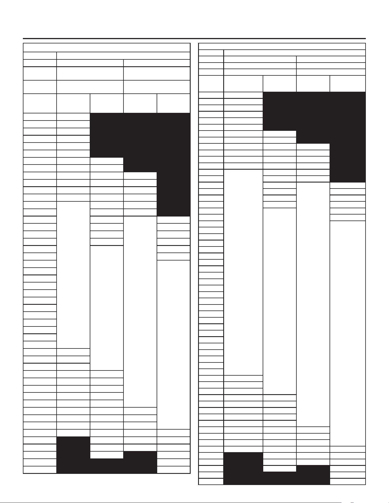
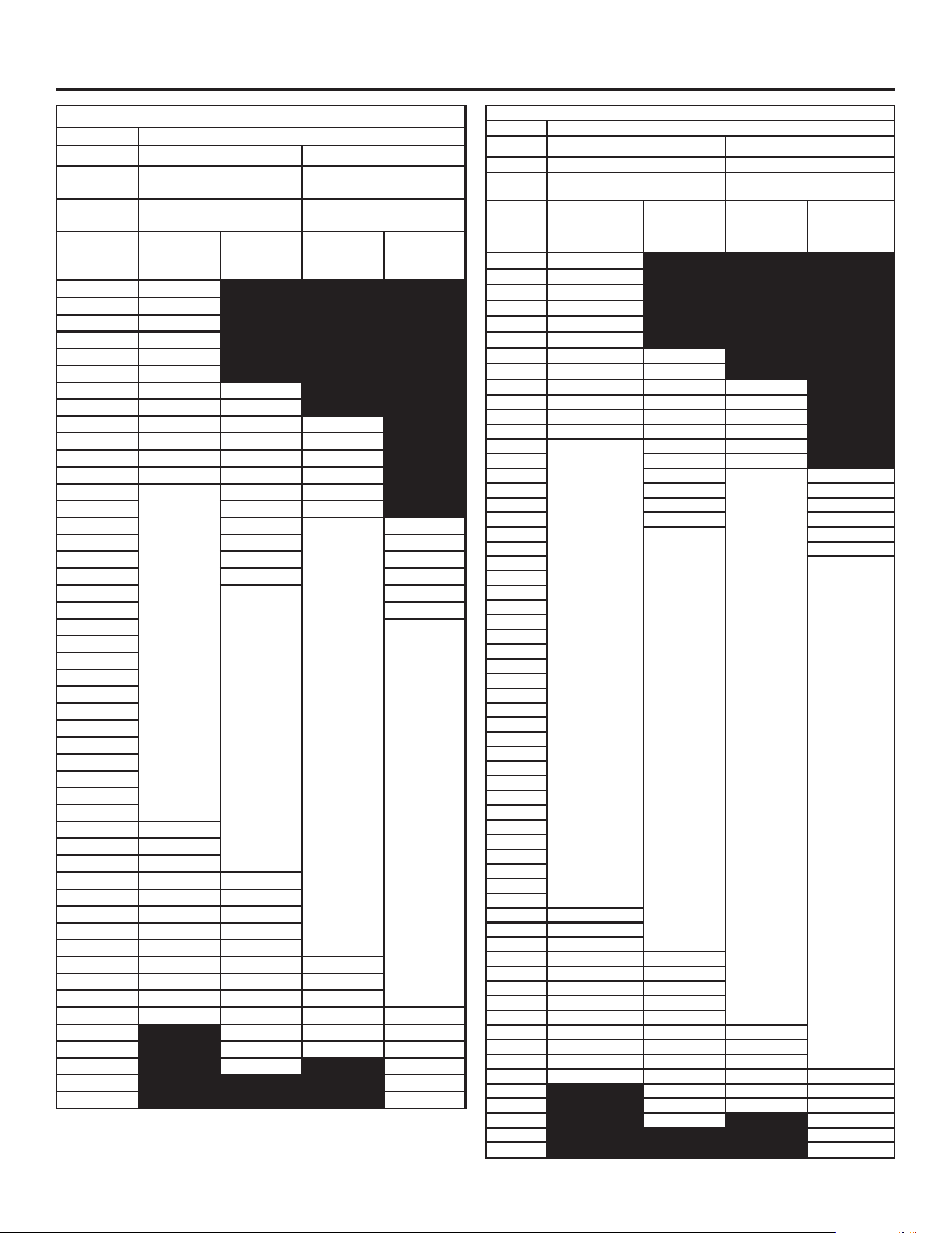
Optional Accessory PX12DC1SWSS
High Ceiling Duct Cover up to 12 ft
Upper Lower
34.56”H x 13.67”W x
11.83”D
28.44”H x 13.81”W x
11.94”D
Installation over Electric
Range
Installation over Gas
Range
Ceiling
Height (ft./
in.)
Vented
Installation
Height
Recirc
Installation
Height
Vented
Installation
Height
Recirc
Installation
Height
8' 4" 24
8' 5" 24 - 25
8' 6" 24 - 26
8' 7" 24 - 27
8' 8" 24 - 28
8' 9" 24 - 29
8' 10" 24 - 30 24
8' 11" 24 - 31 24 - 25
9' 0" 24 - 32 24 - 26 30
9' 1" 24 - 33 24 - 27 30 - 31
9' 2" 24 - 34 24 - 28 30 - 32
9' 3" 24 - 35 24 - 29 30 - 33
9' 4"
24 - 36
24 - 30 30 - 34
9' 5" 24 - 31 30 - 35
9' 6" 24 - 32
30 - 36
30
9' 7" 24 - 33 30 - 31
9' 8" 24 - 34 30 - 32
9' 9" 24 - 35 30 - 33
9' 10"
24 - 36
30 - 34
9' 11" 30 - 35
10' 0"
30 - 36
10' 1"
10' 2"
10' 3"
10' 4"
10' 5"
10' 6"
10' 7"
10' 8"
10' 9"
10' 10"
10' 11"
11' 0" 25 - 36
11' 1" 26 - 36
11' 2" 27 - 36
11' 3" 28 - 26 25 - 36
11' 4" 29 - 36 26 - 36
11' 5" 30 - 36 27 - 36
11' 6" 31 - 36 28 - 26
11' 7" 32 - 36 29 - 36
11' 8" 33 - 36 30 - 36 31 - 36
11' 9" 34 - 36 31 - 36 32 - 36
11' 10" 35 - 36 32 - 36 33 - 36
11' 11" 36
33 - 36 34 - 36 31 - 36
12' 0" 34 - 36 35 - 36 32 - 36
12' 1" 35 - 36 36 33 - 36
12' 2" 36 34 - 36
12' 3" 35 - 36
12' 4" 36
Optional Accessory PX14DC1SWSS
High Ceiling Duct Cover up to 14 ft
Upper Lower
46.56”H x 13.67”W x 11.83”D 40.5”H x 13.81”W x 11.94”D
Installation over Electric Range Installation over Gas Range
Ceiling
Height
(ft./in.)
Vented
Installation
Height
Recirc
Installation
Height
Vented
Installation
Height
Recirc
Installation
Height
9' 4" 24
9' 5" 24 - 25
9' 6" 24 - 26
9' 7" 24 - 27
9' 8" 24 - 28
9' 9" 24 - 29
9' 10" 24 - 30 24
9' 11" 24 - 31 24 - 25
10' 0" 24 - 32 24 - 26 30
10' 1" 24 - 33 24 - 27 30 - 31
10' 2" 24 - 34 24 - 28 30 - 32
10' 3" 24 - 35 24 - 29 30 - 33
10' 4"
24 - 36
24 - 30 30 - 34
10' 5" 24 - 31 30 - 35
10' 6" 24 - 32
30 - 36
30
10' 7" 24 - 33 30 - 31
10' 8" 24 - 34 30 - 32
10' 9" 24 - 35 30 - 33
10' 10"
24 - 36
30 - 34
10' 11" 30 - 35
11' 0"
30 - 36
11' 1"
11' 2"
11' 3"
11' 4"
11' 5"
11' 6"
11' 7"
11' 8"
11' 9"
11' 10"
11' 11"
12' 0"
12' 1"
12' 2"
12' 3"
12' 4"
12' 5"
12' 6"
12' 7"
12' 8"
12' 9"
12' 10"
12' 11"
13' 0" 25 - 36
13' 1" 26 - 36
13' 2" 27 - 36
13' 3" 28 - 26 25 - 36
13' 4" 29 - 36 26 - 36
13' 5" 30 - 36 27 - 36
13' 6" 31 - 36 28 - 26
13' 7" 32 - 36 29 - 36
13' 8" 33 - 36 30 - 36 31 - 36
13' 9" 34 - 36
31 - 36 32 - 36
13' 10" 35 - 36 32 - 36 33 - 36
13' 11" 36 33 - 36 34 - 36 31 - 36
14' 0" 34 - 36 35 - 36 32 - 36
14' 1" 35 - 36 36 33 - 36
14' 2" 36 34 - 36
14' 3" 35 - 36
14' 4" 36
31-7000240 Rev. 2 9
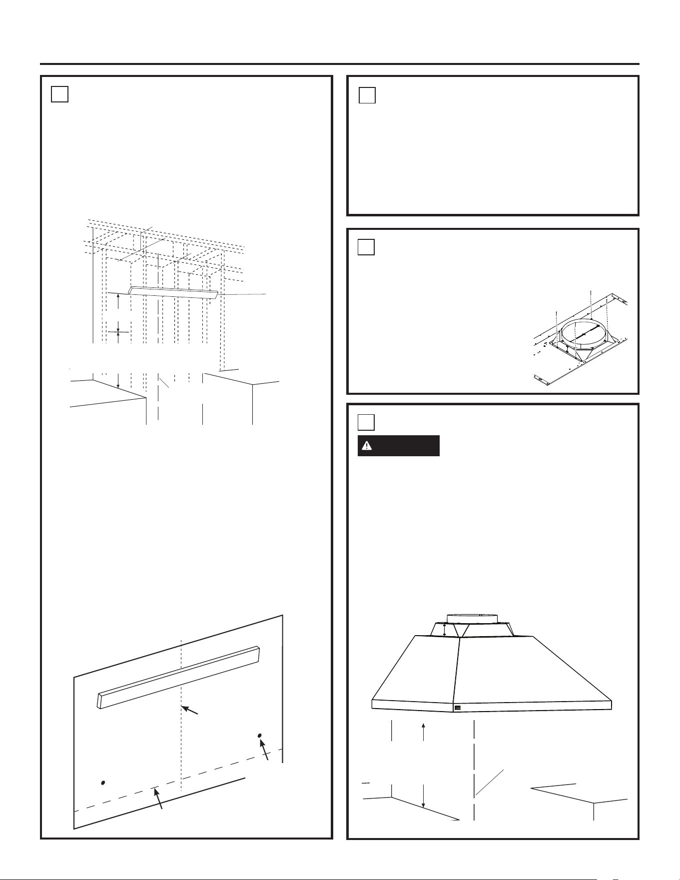
Installation Preparation
DETERMINE HOOD, DUCTWORK AND WIRING LOCATIONS
• This hood can be installed onto the wall or underneath
the soffit.
• For installing the hood to soffit, refer to page 12 for
alternate mounting method.
• Measure desired distance from the bottom of the hood
to the cooking surface, 24” minimum over electric range
or 30” minimum over gas range and 36” recommended
maximum.
• Use a level to draw the cooktop centerline location.
• Measure 8” up from the horizontal line indicating the
bottom of the hood. Draw another horizontal line to
indicate the bottom of the installation bar.
• Use a level to draw the cooktop or range centeline
location.
For Ceiling Ducting:
• If venting out the ceiling, extend the centerline forward
on the ceiling to the back wall.
- Measure 6-1/4” from back wall to mark center point.
- Cut 8” dia. duct hole from center point on the ceiling.
Venting Through a Soffit:
• Follow the same procedure for ceiling ducting to cut
the hole through the top of the soffit.
House Wiring Location:
• The junction box is located inside the hood body
on the left side. See Illustrations for hood knockout
locations.
House wiring may enter the junction box from the rear or
the top of the hood on the left side.
To route house wiring through the ceiling or soffit:
• The wiring can be routed through a knockout on the
back right or front center.
To route house wiring through the wall:
• Measure 4” from the bottom of the hood and mark
location
• Cut a hole approximately 1-1/4” dia. at the marked
location at a distance 7-7/8” to the right of the
centerline based on table below.
• Remove top or rear knockout depending on your
installation.
10 31-7000240 Rev. 2
Installation
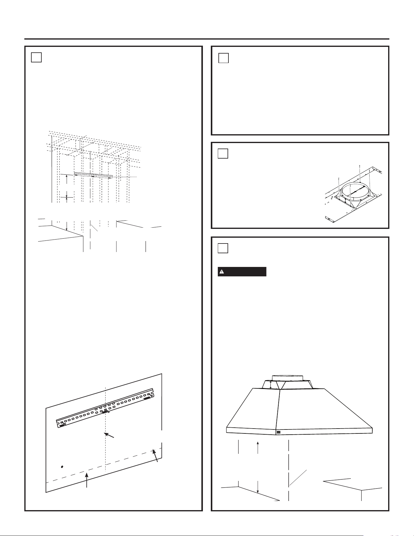
2
INSTALL DAMPER
IMPORTANT: Remove shipping tape from damper
and check that damper moves freely.
Install Top Damper:
• Install the top damper to the hood
body as shown in Figure A using
screws (B) from top of hood.
Figure A
1
INSTALL HOOD SUPPORT (Cont.)
• Install wall anchors (C) by tapping the anchors with
a hammer to seat the teeth of the flanges into the
wall. This keeps anchor from rotating.
• Drive the anchor screws until the barrels crimp
against the inside of the wall.
• Remove the screws from the wall anchors before
installing the hood.
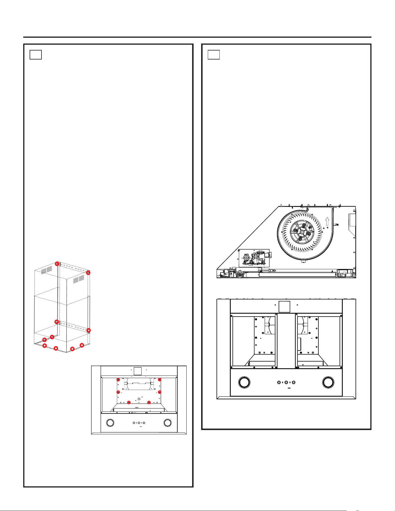
3
INSTALL HOOD ONTO WALL
CAUTION
2 people are required to lift and
position the hood onto the mounting bracket.
• Pull house wiring through knockout at the back or
top of the hood.
• Lift the hood and place over the hooks on the
installation bar. Allow the hood to slide down into
position.
• Check to be sure the hood is level and centered.
• Tighten wall anchor screws (C) to finish hood body
installation to the wall.
• Remove cover from junction box inside the hood.
24” minimum over electric
range or cooktop, or 30”
minimum over gas range
or cooktop, and 36”
recommended maximum.
Centerline of
Installation Space
1
INSTALL HOOD SUPPORT
IMPORTANT: Framing must be capable of supporting
100 lbs.
1. Locate a minimum of 1 vertical stud for the
installation bar by tapping drywall with a hammer or
use a stud finder.
2. Level the installation bar and center left to right
above the marked line. Hold bar against the wall.
3. Drill 1/8” pilot holes at the 1 vertical stud locations
through holes in the installation bracket. Secure the
installation bar with supplied screws (A) as shown
above.
Drill Bottom Mounting Hole Locations:
1. Hang hood on installation bar to mark anchor
locations. Mark hole locations through the back of
the hood.
2. If installing to the cabinet, hold the hood flush to the
cabinet to mark screw hole locations
3. Remove the hood and drill 5/16” clearance holes
centered at the marks you made.
Installation
Bar
Centerline of
Installation Space
8”
24” minimum over electric range
or cooktop, or 30” minimum over
gas range or cooktop, and 36”
recommended maximum.
Bottom of Hood
Centerline of
Installation Space
Wall Anchor
Locations
31-7000240 Rev. 2 11
Installation
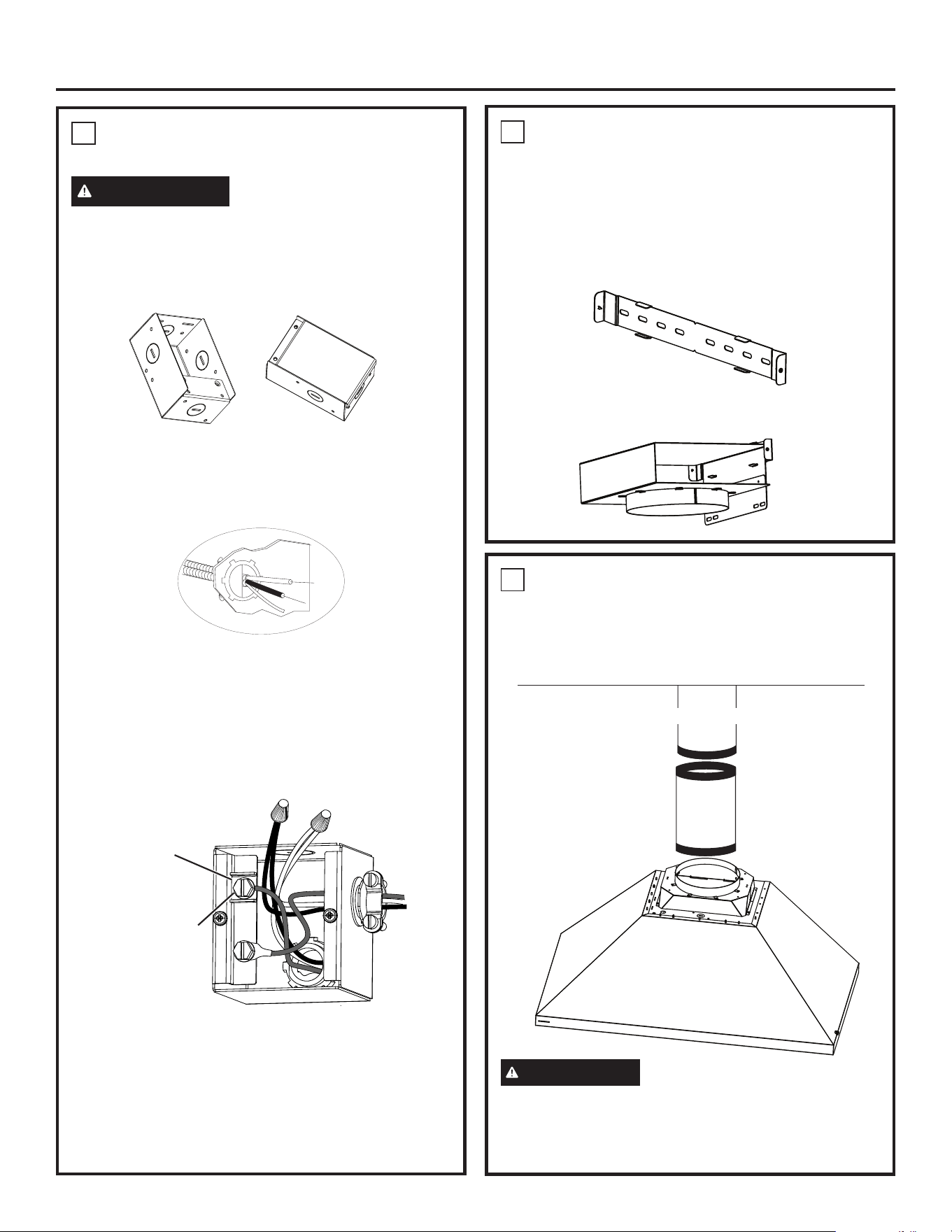
4
CONNECT ELECTRICAL
Verify that power is turned off at the source.
WARNING
If house wiring is not 2-wire with
a ground wire, a ground must be provided by the
installer. When house wiring is aluminum, be sure
to use UL approved anti-oxidant compound and
aluminum-to-copper connectors.
1. Remove junction box cover.
2. Pull the house wiring through the knockout at the
top or back of the hood and secure with the strain
relief.
3. Use UL listed wire nuts to connect incoming white
to white, and black to black wires.
4. Loosen the green grounding screw (with grounding
bracket) in the junction box. Loop solid copper
house wire clockwise around the green grounding
screw and above the bracket. Firmly tighten the
screw over the loop.
5. Replace junction box cover and ensure wires are
not pinched.
NOTE: For corded installation:
Use only with rangehood cord-connection kits that
have been investigated and found acceptable for use
with this model rangehood.
5
INSTALL RECIRCULATION BOX
(IF APPLICABLE)
1. Install the top bracket where the upper portion of the
cover stops using the provided anchors and wood
screws, aligning the center notch with the existing
drawn centerline. Make sure the bracket is level.
2. Using the tabs of the bracket, install the
recirculation box on the tabs.
Grounding Bracket
Green Grounding Screw
6
CONNECT DUCTWORK
1. Connect duct from the bottom of the recirculation
box or connect the vented house ducting to the top
of the damper as shown.
2. Seal all connections with duct tape.
CAUTION
Do not use sheet metal screws at
the transition to ductwork connection. Doing so will
prevent proper damper operations. Seal connection
with tape only.
Ceiling
House Ducting
J Box without cover J Box with cover
12 31-7000240 Rev. 2
Installation
7
INSTALL DUCT COVERS
NOTES: Each duct cover bracket is 1.575” wide and
has a notch at the center. The purpose of the slots is
intended to allow one to use a stud if available along
with a wall anchor.
1. Install the top bracket where the upper portion of
the cover stops using the provided anchors and
wood screws, aligning the center notch with the
existing drawn centerline. Make sure the bracket is
level.
2. Depending on what length of duct cover is used,
draw a level horizontal line located at the bottom
of the top cover. (See page 7 for the upper
cover height.) Align the bottom edge of the lower
bracket with the line and the center notch with the
centerline and mount the bracket with the screws
and anchors.
3. Orient the upper duct cover based on the respective
venting configuration (louvers up for recirculate and
down for vented). Secure the upper cover to the
brackets with the provided machine screws.
4. Install the lower cover by wrapping it around the
lower cover and then securing it with six machine
screws from underneath the top of the hood to the
bottom flange.
Decorative machine screw
attachment locations are circled.
Duct Cover
Assembly
Bottom View
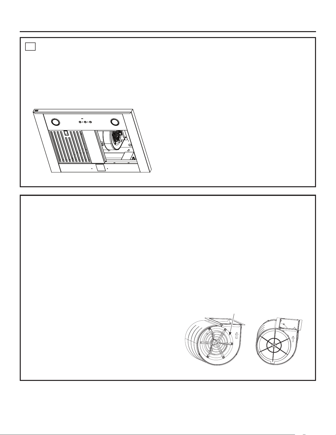
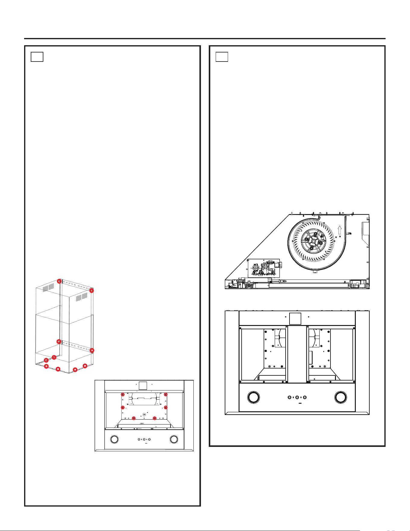
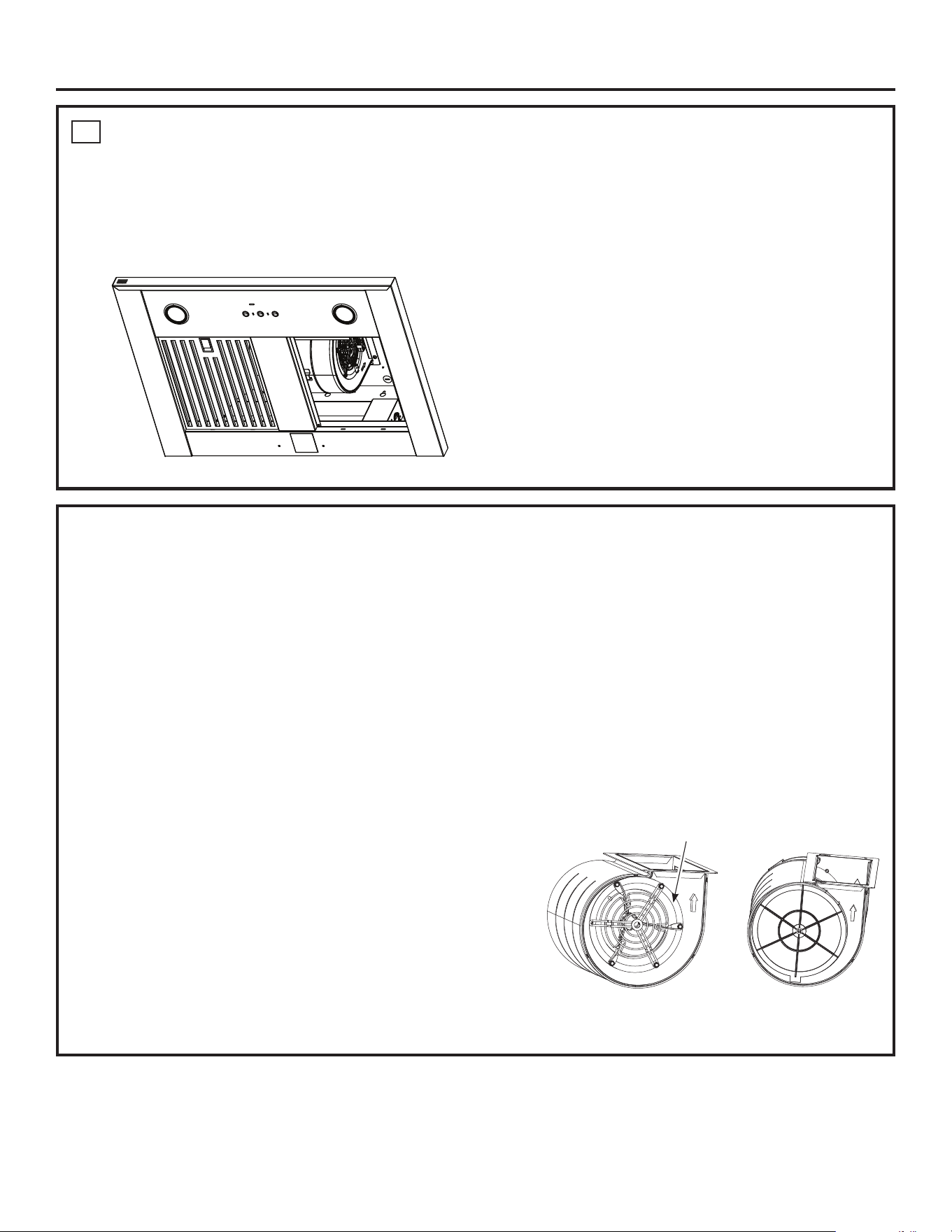
8
INSTALL BLOWER
NOTES: The blower has four through holes for
securing by machine screws to the hood body; two of
which are key holes.
1. For the 30”, the center decorative trim piece will
need to be removed.
2. Noting which holes are key holes, pre-install the
relevant screws to the body.
3. Install the blower by inserting and sliding the
keyholes over the screws.
4. Install the remaining screws through the regular
holes of the blower to the hood body.
5. Tighten all screws.
6. Install the blower wire harness connector to the
control box connector.
7. For the 30” reinstall the decorative trim piece.
31-7000240 Rev. 2 13
Installation
9
INSTALL GREASE FILTERS
1. Remove protective film.
2. Insert the two back tabs of each filter into the back edge of the hood body.
3. Push the button on the latch to open the latch.
4. Install the front edge of the filter into the front edge of the hood body.
5. Release the latch, making sure it is fully engaged
by hearing a click of the latch and the button is
fully released.
Charcoal Filter (for recirculation installation only)
NOTE: DO NOT rinse, or put charcoal filter in an automatic dishwasher.
The charcoal filter is NOT included with the unit. Order charcoal filter UXCF91. It cannot be cleaned; it must
be replaced. It is recommended that the charcoal filter be replaced every 6 months or if it is noticeably dirty
or discolored.
To reduce the risk of fire and shock, when used in recirculation mode, use only charcoal filter UXCF91.
To inquire about purchasing replacement charcoal filters or to find the location of a dealer nearest you, please call
our toll-free number:
National Parts Center 800.626.2002
To Install
1. Remove the grease filters. See Filters section.
2. Install the charcoal filter mounts to either side of the motor using three screws per side.
3. Insert the tab on the charcoal filter into the triangular slot on the mount.
4. Clip the charcoal filter in until it is locked
5. Repeat with second filter on the other side of the motor.
6. Reattach the metal filters. See Filters section.
To Remove
1. Remove grease filters-See Filters section
2. Unclip the charcoal filter by pressing the release clip.
3. Carefully remove charcoal filter from tab.
Charcoal Filter Mount
14 31-7000240 Rev. 2
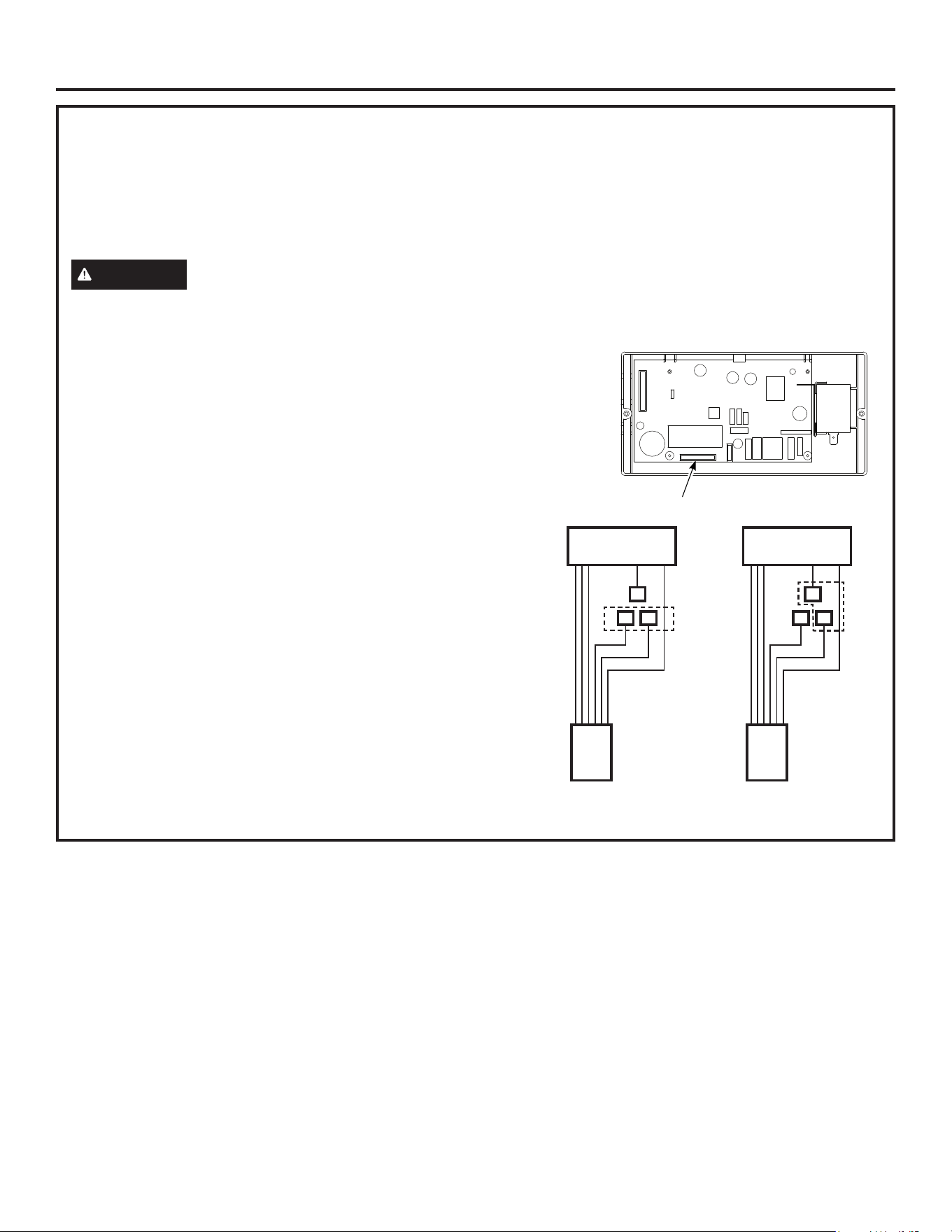
MAKE UP AIR TECHNOLOGY
This operation must be performed by a qualified technician or installer.
Note to Installers and Inspectors: This product comes equipped with a simple installation feature that limits
maximum CFM levels in order to comply with certain local codes or regulations. This installation method may not be
necessary for all installations, please refer to your local codes for further guidelines.
This makeup air feature applies to single motor models only.
CAUTION
Hood must be disconnected from main power prior performing the conversion instructions listed
below. Failure to do so could result in personal injury or damage to the product.
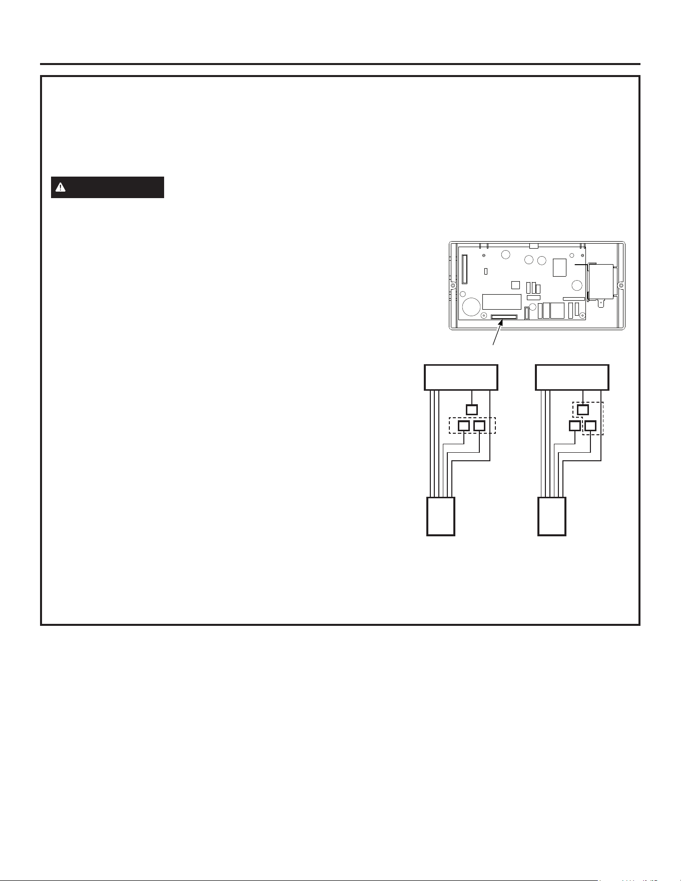
To modify unit (if needed for local codes):
390CFM
By design, the maximum blower speed is greater than 400 CFM. For local
codes requiring reduced CFM, modify the wiring as described below:
1. Remove the Baffle filters.
2. Disconnect all the harnesses from the top of control box on right side of
motor
3. Loosen the screws on top of control box and slide out to remove it from
the hood
4. Uninstall the control box cover
5. For a maximum of 390 CFM Unit can operate with 4 speeds (Low,
Medium, High, Boost).
i. Disconnect connectors of the BROWN wire.
ii. Remove the cap attached to the connector of the RED wire.
iii. Connect the mating connector of the BROWN wire and the
RED wire.
iv. Attach the cap to the open BROWN wire connector.
6. Reinstall control box cover and secure control box to the bracket in
the hood using the two screws
7. Connect all harnesses on top of the control box
8. Reinstall filters.
Note to Inspectors: To verify this product installation, check motor
wiring connections as described above.
Installation
Motor Harness Connector
Blue
Red
Red
Motor Harness
Brown
Blue
Red
Red
Motor Harness
Brown
Brown
Factory Installed
Wiring Setup
Max 390 CFM Boost
Wiring Setup
Brown
30” and 36”
Vent Hood
Instrucciones
de instalación
ANTES DE COMENZAR
Lea estas instrucciones por completo y con detenimiento.
■ IMPORTANTE – Guardeestasinstrucciones
paraelusodeinspectoreslocales.
■ IMPORTANTE – Cumplacontodosloscódigos
yordenanzasvigentes.
■ Nota al instalador – Asegúresededejarestas
instruccionesconelConsumidor.
■ Nota al consumidor – Conserveestasinstruccionespara
referenciafutura.
■ Nivel de capacidad – Lainstalacióndeestacampanade
ventilaciónrequierecapacidadesmecánicasyeléctricas
básicas..
■ Tiempo de nalización – Aproximadamente
de1a3horas.
■ Elinstaladortienelaresponsabilidaddeefectuaruna
instalaciónadecuada.
■ LaGarantíanocubrelasfallasdelproductodebidoauna
instalaciónincorrecta.
PVW1030, PVW1036
31-7000240Rev.208-24
Ante cualquier duda, llame a GE Appliances al 800.GE.CARES (800.432.2737)
o visite nuestro sitio Web en: GEAppliances.com
PRECAUCIÓN
Debidoalpesoytamañodeestascampanasdeventilaciónyparareducirelriesgodelesiones
personalesodañosalproducto,SE NECESITAN DOS PERSONAS PARA REALIZAR UNA INSTALACIÓN CORRECTA.
PRECAUCIÓN
Debidoalpesoytamañodeestascampanasdeventilaciónyparareducirelriesgodelesiones
personalesodañosalproducto,SE NECESITAN DOS PERSONAS PARA REALIZAR UNA INSTALACIÓN CORRECTA.
ADVERTENCIA
Parareducirelriesgodeincendioodescargaeléctrica,noutiliceestacampanaparaestufacon
ningúndispositivodecontroldevelocidadexternodeestadosólido.Cualquierclasedemodificacióndelcableadooriginalde
fábricapodríaprovocardañosalaunidady/ocrearunpeligrodeseguridadeléctrico.
PARA REDUCIR EL RIESGO DE INCENDIO, SÓLO UTILICE CONDUCTOS DE METAL.
ADVERTENCIA
PARA REDUCIR EL RIESGO DE INCENDIO, DESCARGA ELÉCTRICA O LESIONES A
PERSONAS, CUMPLA CON LOS SIGUIENTES PUNTOS:
A. Utiliceestaunidadsólodelamaneraconcebidaporelfabricante.Sitienealgunapregunta,comuníqueseconelfabricante.
B. Antesderealizarreparacionesolimpiarlaunidad,desconectelaenergíadelpaneldeservicioybloqueelosmediosde
desconexiónparaevitarelaccionamientodelaenergíademaneraaccidental.Cuandolosmediosdedesconexiónde
servicionopuedenbloquearse,coloquesobreelpaneldeservicioundispositivodeadvertenciabienvisible,comouna
etiqueta.
PRECAUCIÓN
SÓLO PARA USO DE VENTILACIÓN GENERAL. NO LO UTILICE PARA VENTILAR MATERIALES
PELIGROSOS NI MATERIALES O VAPORES EXPLOSIVOS.
2 31-7000240 Rev. 2
Safety Information
READ AND SAVE THESE INSTRUCTIONS
ADVERTENCIA
PARA REDUCIR EL RIESGO DE INCENDIO, DESCARGA ELÉCTRICA O LESIONES A
PERSONAS, CUMPLA CON LOS SIGUIENTES PUNTOS:
■ Eltrabajodeinstalaciónyelcableadoeléctricodebenrealizarlopersonascalificadasencumplimientocontodosloscódigos
ynormasaplicables,incluyendoconstrucciónconclasificaciónparaincendios.
■ Senecesitasuficienteaireparaunacombustiónyescapedegasesadecuadosatravésdelaventilación(chimenea)de
equipamientodecombustióndecombustibleparaevitarlacontracorriente.Sigalaspautasynormasdeseguridadde
fabricantedelequipamientodecalefacción,talescomolaspublicadasporlaAsociaciónNacionaldeProteccióncontra
Incendios(NFPA),laSociedadEstadounidensedeIngenierosenCalefacción,RefrigeraciónyAireAcondicionado(ASHRAE)
ylasautoridadesdecódigoslocales.Cuandocorresponda,instaleunsistemadereposición(reemplazo)deairedeacuerdo
conlosrequisitosdelcódigolocaldeconstrucción.Paraaccederasolucionesdeairedisponibles,visiteGEAppliances.
com.
■ Cuandorealicecortesoperforacionesdentrodeparedesocielorrasos,nodañeelcableadoeléctriconiotrosservicios
públicosocultos.
■ Lossistemasdeconductossiempredebencontarconunasalidaalexterior.
■ Loscódigoslocalespuedenvariar.Lainstalacióndeconexioneseléctricasyatierradebecumplirconloscódigosaplicables.
Sinoexistierancódigoslocales,laventilacióndeberáinstalarseencumplimientoconelCódigoEléctricoNacionalANSI/
NFPA70-1990olaúltimaedición.
PRECAUCIÓN
Parareducirelriesgodeincendiooparaqueelaireseventiledemaneraadecuada,asegúresede
queelairesalgaalexterior;noventileairedeescapeenespaciosdentrodeparedesocielorrasosodentrodeáticos,huecos
sanitariosogarajes.
DIMENSIONES Y MARJENS DEL
PRODUCTO
Lacampanade
ventilacióndebe
instalarseaunmín.de
24″yunmáx.de30″
sobrelasuperficiede
cocción.
NOTA:Laalturade
instalacióndebemedirse
desdelasuperficiede
cocciónhastalaparte
másbajadelacampana.
PX8DC1SWSS Accesorio de cubierta de conducto
Esteaccesorioseencuentradisponibleparainstalacionescon
cielorrasosdeunaalturade9′a10′omás.Verlatabladela
página43.
Elaccesoriodecubiertadeconductodebeencontrarseenel
sitioconlacampanaenelmomentodelainstalación.
24″Mínimo
30″Máximum
36″Mínimo
*Alturahasta
elcielorraso
11-1/8”
21-1/2”
30”,PVW1030
36”,PVW1036
31-7000240 Rev. 2 3
Preparación para la instalación
PLANIFICACIÓN DE LOS CONDUCTOS
■Estacampanaestádiseñadaparaventilarseenforma
verticalatravésdelcielorraso.Utilicecodossuministrados
enformalocalparaventilaciónhorizontalatravésdela
paredtrasera.
■Determinelaubicaciónexactadelacampanade
ventilación.
■Planifiqueelrecorridodelasalidadeventilaciónhaciael
exterior.
■Utiliceelrecorridodeconductosmáscortoymásrecto
posible.Paraundesempeñosatisfactorio,elrecorridode
losconductosnodebesuperarunalongitudequivalentea
los150′paraningunaconfiguracióndeconductos.
■Consultelatabla“Accesoriosdeconductos”para
calcularlalongitudmáximapermisiblepararecorridosde
conductoshaciaelexterior.
■Sólouseconductosdemetalrígidos.
■Estacampanadeventilacióndebeutilizarunconducto
redondode8″.
■Instaleelconductodomésticoparaquecorraenforma
horizontalentrelasvigasdelcielorrasooenformarectaa
travésdeltecho.
■Instaleunacubiertadeparedocasquetedetechocon
unreguladordetiroenlaaberturaexterior.Solicitepor
adelantadolacubiertadeparedoelcasquetedetechoy
cualquiertransiciónolongituddeconductonecesarios.
■Cuandocorresponda,instaleunsistemadereposición
(reemplazo)deairedeacuerdoconlosrequisitosdel
códigolocaldeconstrucción.Paraaccederasoluciones
deairedisponibles,visiteGEAppliances.com.
ADVERTENCIA
PARA REDUCIR EL RIESGO
DE INCENDIO, SÓLO UTILICE CONDUCTOS DE METAL
RÍGIDOS.
ARMAZONES DE PARED PARA UN
SOPORTE ADECUADO
■Estacampanadeventilaciónespesada.Debecontarse
conunsoporteestructuraladecuado.Estacampanadebe
fijarseacolumnasverticalesdelapared.Verpágina44o
49.
■Recomendamosenfáticamentequelacampanade
ventilaciónconcubiertadeconductoseencuentreen
ellugarantesdecolocarlosarmazonesyefectuarel
acabadodelapared.Estotambiénayudaráaubicarcon
precisiónlosconductosyelservicioeléctrico.
■Lainstalaciónresultarámásfácilsilacampanade
ventilaciónseinstalaantesquelaestufayelmostrador
deencimera.
PLANIFICACIÓN PREVIA
Suinstalacióndecampanapuedenecesitarunaccesorio
decubiertadeconductosdependiendodelaalturadel
cielorraso.
4 31-7000240 Rev. 2
Preparación para la instalación
SUMINISTRO DE ENERGÍA
IMPORTANTE – (Tenga a bien leer cuidadosamente)
WARNING
PARASEGURIDADPERSONAL,ESTE
APARATODEBECONECTARSEATIERRADEMANERA
ADECUADA.
Quiteelfusibleoabraelinterruptordecircuitosantesde
comenzarlainstalación.
Noutiliceuncabledeextensiónounenchufeadaptador
conesteartefacto.SigaelCódigoEléctricoNacionalolos
códigosyordenanzaslocalesvigentes.
Suministro eléctrico
Estacampanadeventilacióndebencontarconun
suministrode120V,60Hz,ydebeestarconectadaaun
circuitoderivadoindividualconunaadecuadaconexióna
tierraydebecontarconlaproteccióndeuninterruptorde
circuitoounfusibleconretrasode15o20amperios.
■Elcableadodebeserde2hilosconconexiónatierra.
■Sielsuministroeléctriconocumpleconlosrequisitos
anteriores,llameaunelectricistaconlicenciaantesde
continuar.
■Dirijaelcableadodomésticolomáscercanoala
instalaciónposible.Elcableadopuedeingresardesdeel
cielorrasoolaparedtrasera.Dirijalalongitudadicional
desdeelcielorrasoolaparedparaalcanzarlacajade
conexiones.
■Conecteelcableadoalcableadodomésticoen
cumplimientoconloscódigoslocales.
Instrucciones de conexión a tierra
Elconductoratierradebeconectarseaunmetalcon
conexiónatierra,unsistemadecableadopermanenteouna
terminaloconductordeconexiónatierraenlacampana.
ADVERTENCIA
Unaconexióninadecuadadel
conductordeconexiónatierradelequipamientopuede
provocarunriesgodedescargaeléctrica.Consulteaun
electricistacalificadoorepresentantedeserviciotécnicosi
tienedudassobrelacorrectaconexiónatierradelaparato.
HERRAMIENTAS Y MATERIALES
REQUERIDOS (No Suministrados)
Cinta
adhesiva
Guantes
Cuchillodeuso
general
Alicates
Alicatepelacables
Niveldeburbujadeaire
Cinta
aislantede
aluminio
Gafasdeseguridad
Cablede120V,60Hz,15o20amperios
de2hilosconcircuitoderivadocon
conexiónatierra
Electrical Cable
Escalera
Sierrasableoserruchodecalar
Destornillador
deestrella
Aliviodetensión
paralacajade
conexiones
Strain Relief I
Conductodemetalredondo
de8″longitudsuficiente
paralainstalación
Martillo
Perforadoraeléctricaconbrocas
de1/8″,deestrellaN°2ycabeza
planayT20torxextensiónde
destornilladorde6”
Linterna
Taponesdealambre
aprobadosporUL
Wire Nuts
Lápizycintamétrica
31-7000240 Rev. 2 5
CONTROLE LAS PIEZAS DE INSTALACIÓN
Ubiquelacajadepiezasembaladaconlacampanayverifique
loscontenidos.
QUITE EL ENVOLTORIO
PRECAUCIÓN
Useguantesparaprotegersede
ladosafilados.
■Quitelacubiertadeconductos,lacajadepiezasyel
embalajedepoliestireno.
■Levanteyquitelacampanadelacaja.
■Quiteydesecheadecuadamenteelenvoltorioplástico.
■Quitelosfiltrosdegrasametálicosyelenvoltoriodelabarra
lateral.
■
Quitelatapadelacajadeconexiones.
■Quiteelcaladodelacajadeconexiones.
■Instaleelaliviodetensiónenlacajadeconexiones.
Preparación para la instalación
Tornillodemontaje
Tabladeembalaje
Tornillodemontaje
Tornillodemontaje
Calado
Cajadeconexiones
Piezas adicionales para la operación de recirculación.
Accesoriosopcionalesadquiridosaparte
658Dia37
Nuevetornillos
demaderade2”
2filtrosde
grasadeacero
inoxidable(30”)
o3Filtrosde
grasadeacero
inoxidable(36”)
Cubiertas
deconducto
decorativas
10tornillos
delatapa
delconducto
NOTA: Senecesitanherramientas,materialesypiezasdeferretería
adicionalesparaconstruirelsoportedearmazóndepared.
2filtrosdecarbón
(UXCF91)
8anclajes
Barrade
madera
2soportesdela
tapadelconducto
Cajade
Recirculación
(UXCN36)
1ClipparaCable
Autoadhesivo
Ensambledel
Reguladorde8”
6tornillosdel
regulador
TresTornillos
deMadera
de3”
Cuerpodela
Campana
6 31-7000240 Rev. 2
Preparación para la instalación
DETERMINE LA ALTURA DE INSTALACIÓN
■Seincluyeunatapadeconductotelescópicoparaunaalturadecielorrasode10’paraocultarelconductoquecirculahaciael
cielorraso.Lasalturasdecielorrasode8’,12’,o14’sepodránacomodarconlosaccesoriosopcionales.
■Estacampanasepodráinstalarparaunfuncionamientoconventilaciónorecirculación(modelode36”deanchoúnicamente).
NOTA: La altura de la instalación se deberá medir desde la superficie de cocción hasta la parte inferior de la campana.
Lacampanadeventilaciónsedeberáinstalarporencimadelasuperficiedecocciónaunaalturamínimade24”hastauna
alturamáximade30”,yunmínimode30”hastaunmáximode36”paraelgas.Laalturadeinstalacióndelacampana,desde
lasuperficiedecocciónhastalaparteinferiordelacampana,dependedelaalturadelcielorrasoydelaslimitacionesdelatapa
delconducto.
Mín.de24”/Máx.de30”(Eléctrica)
Mín.de30”/Máx.de36”(Eléctrica)
36″Mínimo
31-7000240 Rev. 2 7
Preparación para la instalación
Accesorio Incluido
Tapa del Conducto del Cielorraso Alto de hasta 10 pies
Superior Inferior
25.56”H x 13.67”W x 11.83”D 19.50”H x 13.81”W x 11.94”D
Instalación sobre Estufa
Eléctrica
Instalación sobre Estufa a
Gas
Altura del
Cielorraso
(pies/ pulg.)
Altura de
Instalación con
Ventilación
Altura de
Instalación con
Recirculación
Altura de
Instalación con
Ventilación
Altura de
Instalación con
Recirculación
7'7" 24
7'8" 24-25
7'9" 24-26
7'10" 24-27
7'11" 24-28
8'0" 24-29
8'1" 24-30 24
8'2" 24-31 24-25
8'3" 24-32 24-26 30
8'4" 24-33 24-27 30-31
8'5" 24-34 24-28 30-32
8'6" 24-35 24-29 30-33
8'7"
24-36
24-30 30-34
8'8" 24-31 30-35
8'9" 24-32
30-36
30
8'10" 24-33 30-31
8'11" 24-34 30-32
9'0" 24-35 30-33
9'1"
24-36
30-34
9'2" 30-35
9'3"
30-36
9'4"
9'5"
9'6" 25-36
9'7" 26-36
9'8" 27-36
9'9" 28-26 25-36
9'10" 29-36 26-36
9'11" 30-36 27-36
10'0" 31-36 28-26
10'1" 32-36 29-36
10'2" 33-36 30-36 31-36
10'3" 34-36 31-36 32-36
10'4" 35-36 32-36 33-36
10'5" 36 33-36 34-36 31-36
10'6" 34-36 35-36 32-36
10'7" 35-36 36 33-36
10'8" 36 34-36
10'9" 35-36
10'10" 36
Accesorio opcional PX8DC1SWSS
Tapa del Conducto del Cielorraso Alto de hasta 8 pies
Superior Inferior
22.06”H x 13.67”W x 11.83”D 16.00”H x 13.81”W x 11.94”D
Instalación sobre Estufa
Eléctrica
Instalación sobre Estufa a
Gas
Altura del
Cielorraso
(pies/ pulg.)
Altura de
Instalación con
Ventilación
Altura de
Instalación con
Recirculación
Altura de
Instalación con
Ventilación
Altura de
Instalación con
Recirculación
7'4" 24
7'5" 24-25
7'6" 24-26
7'7" 24-27
7'8" 24-28
7'9" 24-29
7'10" 24-30 24
7'11" 24-31 24-25
8'0" 24-32 24-26 30
8'1" 24-33 24-27 30-31
8'2" 24-34 24-28 30-32
8'3" 24-35 24-29 30-33
8'4"
24-36
24-30 30-34
8'5" 24-31 30-35
8'6" 24-32
30-36
30
8'7" 24-33 30-31
8'8" 24-34 30-32
8'9" 24-35 30-33
8'10"
24-36
30-34
8'11" 25-36 30-35
9'0" 26-36
30-36
9'1" 27-36
9'2" 28-26 25-36
9'3" 29-36 26-36
9'4" 30-36 27-36
9'5" 31-36 28-26
9'6" 32-36 29-36
9'7" 33-36 30-36 31-36
9'8" 34-36 31-36 32-36
9'9" 35-36 32-36 33-36
9'10" 36 33-36 34-36 31-36
9'11" 34-36 35-36 32-36
10'0" 35-36 36 33-36
10'1" 36 34-36
10'2" 35-36
10'3" 36
8 31-7000240 Rev. 2
Preparación para la instalación
Accesorio opcional PX12DC1SWSS
Tapa del Conducto del Cielorraso Alto de hasta 12 pies
Superior Inferior
34.56”H x 13.67”W x 11.83”D 28.44”H x 13.81”W x 11.94”D
Instalación sobre Estufa
Eléctrica
Instalación sobre Estufa a
Gas
Altura del
Cielorraso
(pies/ pulg.)
Altura de
Instalación con
Ventilación
Altura de
Instalación con
Recirculación
Altura de
Instalación con
Ventilación
Altura de
Instalación con
Recirculación
8'4" 24
8'5" 24-25
8'6" 24-26
8'7" 24-27
8'8" 24-28
8'9" 24-29
8'10" 24-30 24
8'11" 24-31 24-25
9'0" 24-32 24-26 30
9'1" 24-33 24-27 30-31
9'2" 24-34 24-28 30-32
9'3" 24-35 24-29 30-33
9'4"
24-36
24-30 30-34
9'5" 24-31 30-35
9'6" 24-32
30-36
30
9'7" 24-33 30-31
9'8" 24-34 30-32
9'9" 24-35 30-33
9'10"
24-36
30-34
9'11" 30-35
10'0"
30-36
10'1"
10'2"
10'3"
10'4"
10'5"
10'6"
10'7"
10'8"
10'9"
10'10"
10'11"
11'0" 25-36
11'1" 26-36
11'2" 27-36
11'3" 28-26 25-36
11'4" 29-36 26-36
11'5" 30-36 27-36
11'6" 31-36 28-26
11'7" 32-36 29-36
11'8" 33-36 30-36 31-36
11'9" 34-36 31-36 32-36
11'10" 35-36 32-36 33-36
11'11" 36 33-36 34-36 31-36
12'0" 34-36 35-36 32-36
12'1" 35-36 36 33-36
12'2" 36 34-36
12'3" 35-36
12'4" 36
Accesorio opcional PX14DC1SWSS
Tapa del Conducto del Cielorraso Alto de hasta 14 pies
Superior Inferior
46.56”H x 13.67”W x 11.83”D 40.5”H x 13.81”W x 11.94”D
Instalación sobre Estufa
Eléctrica
Instalación sobre Estufa a Gas
Altura del
Cielorraso
(pies/
pulg.)
Altura de
Instalación con
Ventilación
Altura de
Instalación con
Recirculación
Altura de
Instalación con
Ventilación
Altura de
Instalación con
Recirculación
9'4" 24
9'5" 24-25
9'6" 24-26
9'7" 24-27
9'8" 24-28
9'9" 24-29
9'10" 24-30 24
9'11" 24-31 24-25
10'0" 24-32 24-26 30
10'1" 24-33 24-27 30-31
10'2" 24-34 24-28 30-32
10'3" 24-35 24-29 30-33
10'4"
24-36
24-30 30-34
10'5" 24-31 30-35
10'6" 24-32
30-36
30
10'7" 24-33 30-31
10'8" 24-34 30-32
10'9" 24-35 30-33
10'10"
24-36
30-34
10'11" 30-35
11'0"
30-36
11'1"
11'2"
11'3"
11'4"
11'5"
11'6"
11'7"
11'8"
11'9"
11'10"
11'11"
12'0"
12'1"
12'2"
12'3"
12'4"
12'5"
12'6"
12'7"
12'8"
12'9"
12'10"
12'11"
13'0" 25-36
13'1" 26-36
13'2" 27-36
13'3" 28-26 25-36
13'4" 29-36 26-36
13'5" 30-36 27-36
13'6" 31-36 28-26
13'7" 32-36 29-36
13'8" 33-36 30-36 31-36
13'9" 34-36 31-36 32-36
13'10" 35-36 32-36 33-36
13'11" 36 33-36 34-36 31-36
14'0" 34-36 35-36 32-36
14'1" 35-36 36 33-36
14'2" 36 34-36
14'3" 35-36
14'4" 36
31-7000240 Rev. 2 9
DETERMINE LAS UBICACIONES DE LA CAMPANA, EL CONDUCTO Y EL CABLEADO
•Estacampanasepodráinstalarsobrelaparedodebajodelsofito.
•Parainstalarlacampanaenelsofitoogabinete,consulteenlapágina12sobreunmétododemontajealternativo.
•Midaladistanciadeseadadesdelaparteinferiordelacampanahastalasuperficiedecocción,conunmínimode24”sobre
unacocinaeléctricaounmínimode30”sobreunacocinaagasyunmáximorecomendadode36”.
•Useunnivelparadibujarlaubicacióndelalíneacentraldelasuperficiedecocción.
•Mida8”desdelalíneahorizontalqueindicalaparteinferiordelacampana.Dibujeotralíneahorizontalparaindicarlaparte
inferiordelabarradeinstalación.
•Useunnivelparadibujarlaubicacióndelalíneacentraldelasuperficiedecocciónodelacocina.
Para un Conducto en Cielorraso:
•Siventilaráatravésdelcielorraso,extiendalalíneacentralhaciaadelantesobreelcielorrasohastalaparedtrasera.
-Mida6¼”desdelaparedtraseraparamarcarelpuntocentral.
-Hagaunagujeroparaconductode8”dediámetrodesdeelpuntocentralsobreelcielorraso.
Ventilación a Través de un Sofito:
• Sigaelmismoprocedimientoparaconductosdecielorrasoparacortarelagujeroatravésdelapartesuperiordelsofito.
Ubicación del Cableado Hogareño:
•Lacajadeempalmesseencuentraubicadadentrodel
cuerpodelacampanasobreelladoizquierdo.Consultelas
ilustracionesparaconocerlasubicacionesdeltablerodela
campana.
Elcableadohogareñopodráingresaralacajadeempalmes
desdelapartetraseraodesdelapartesuperiordela
campana,sobreelladoizquierdo.
Para conducir el cableado hogareño a través del cielorraso
o sofito:
•Elcableadosepodráhacercircularatravésdelastapas
sobrelapartetraseraderechaolapartecentraldelfrente.
Para conducir el cableado hogareño a través de la pared:
• Mida4”desdelaparteinferiordelacampanaymarquela
ubicación.
• Hagaunagujerodeaproximadamente1¼”dediámetro
enlaubicaciónmarcadaaunadistanciade77/8”sobrela
derechadelalíneacentral,enbasealasiguientetabla.
• Retireeltablerosuperiorotrasero,dependiendodesu
instalación.
Preparación para la instalación
10 31-7000240 Rev. 2
Instalación
2
INSTALE EL REGULADOR
IMPORTANTE:Retirelacintade
embalajedelreguladorycontroleque
esteúltimosemuevalibremente.
Instale el Regulador Superior:
•Instaleelreguladorsuperioralcuerpo
delacampanacomosemuestraen
laFiguraA,usandolostornillos(B)
delapartesuperiordelacampana.
Figura A
1
INSTALACIÓN DEL SOPORTE DE
LA CAMPANA (Cont.)
•Instalelosanclajesdepared(C)golpeandolosmismos
conunmartilloparaasentarlosdientesdelasbridas
sobrelapared.Estoevitaqueelanclajeruede.
•Coloquelostornillosdeanclajehastaqueloscilindros
quedenenganchadosdentrodelapared.
•Retirelostornillosdelosanclajesdeparedantesde
instalarlacampana.
3
INSTALACIÓN DE LA CAMPANA
EN LA PARED
PRECAUCIÓN
Serequieren2personasparalevantary
posicionarlacampanasobreelsoportedemontaje.
•Paseelcableadohogareñoatravésdeltablerosobrela
partetraseraosuperiordelacampana.
•Levantelacampanaycoloquelamismasobrelosganchos
enlabarradeinstalación.Permitaquelacampanase
deslicehastasuposición.
•Asegúresedequelacampanaesténiveladay
centrada.
•Ajustelostornillosdeanclajedepared(C)parafinalizarla
instalacióndelcuerpodelacampanasobrelapared.
•Retirelatapadelacajadeempalmesdentrodela
campana.
Línea Central del
Espacio de Instalación
Mínimode24”sobrelacocina
eléctricaosobrelasuperficie
decocción,omínimode30”
sobrelacocinaagasosobrela
superficiedecocción,ymáximo
de36”recomendado
1
INSTALE EL SOPORTE DE LA
CAMPANA
IMPORTANTE:Elmarcodeberápodersoportar100lbs.
1.Ubiquemínimamente1vigaverticaleparalabarrade
instalación,golpeandolapareddeyesoconunmartilloo
usandoundetectordevigas.
2.Nivelelabarradeinstalaciónycentredeizquierdaa
derechasobrelalíneamarcada.Sostengalabarracontra
lapared.
3.Perforeagujerospilotode1/8”enlas1ubicacionede
montajeverticale,atravésdelosagujerosdelsoporte
deinstalación.Asegurelabarradeinstalaciónconlos
tornillossuministrados(A)comosemuestramásarriba.
Perfore las Ubicaciones de los Agujeros de Montaje
Inferiores:
1.
Cuelgueelganchosobrelabarradeinstalación
paramarcarlasubicacionesdelanclaje.Marquelas
ubicacionesdelosagujerosatravésdelapartetrasera
delacampana.
2.Silainstalaciónseharáengabinete,presionela
campanahastaquequedeniveladaconogabineteantes
demarcarlasubicacionesdelosagujerosdelostornillos.
3.Retirelacampanayperforelosagujerosdelosespacios
libresde5/16”centradosenlasmarcasqueustedrealizó.
BarradeInstalación
LíneaCentraldel
EspaciodeInstalación
8”
Mínimode24”sobrelacocinaeléctricaosobre
lasuperficiedecocción,omínimode30”sobrela
cocinaagasosobrelasuperficiedecocción,y
máximode36”recomendado
ParteInferior
delaCampana
LíneaCentraldel
EspaciodeInstalación
Ubicaciones
deanclajesde
pared
31-7000240 Rev. 2 11
Instalación
6
CONECTE EL CONDUCTO
1.Conecteelconductodesdelaparteinferiordelacajade
recirculaciónoconectelatuberíadeventilaciónhogareña
enlapartesuperiordelregulador,comosemuestra.
2.Selletodaslasconexionesconcintaparaconductos.
PRECAUCIÓN
Nousetornillosmetálicospara
planchasenlatransiciónalaconexióndelconducto.Hacer
estoimpediráelfuncionamientocorrectodelosreguladores.
Sellelaconexiónconcintaúnicamente.
Cielorraso
ConductoHogareño
4
CONECTE LA ELECTRICIDAD
Verifiquequelacorrienteestéapagadaenlafuente.
Sielcableadodelhogarno
tiene2cablesconunoatierra,el
instaladordeberáproveerunaconexiónatierra.Cuandoel
cableadohogareñoseadealuminio,asegúresedeusarun
compuestoantioxidanteyconectoresdealuminioacobre
aprobadosporUL.
1.Retirelatapadelacajadeempalmes.
2.Paseelcableadohogareñoatravésdeltableroenla
partesuperiorotraseradelacampanayasegureel
mismoconunamortiguadorderefuerzo.
3.UsetuercasparacablesdelalistadeULparaconectar
loscablesentrantesblancoconblancoynegrocon
negro.
4.
Aflojeeltornillodeconexiónatierraverde(conelsoporte
deconexiónatierra)enlacajadeempalmes.Enrolle
elcablehogareñodecobresólidoendirecciónhoraria
alrededordeltornillodeconexiónatierraverdeysobreel
soporte.Demanerafirme,ajusteeltornillosobreelrollo.
5.Reemplacelatapadelacajadeempalmesyasegúrese
dequeloscablesnohayansufridopellizcos.
NOTA: Para una instalación con cables:
uselamismasóloconloskitsdeconexióndecablespara
campanasdecocinaquefueroninvestigadosyquese
encontróquesuusoesaceptableconestemodelode
campanaparacocina.
ADVERTENCIA
Soportede
ConexiónaTierra
TornilloVerdede
ConexiónaTierra
CajaJsintapa CajaJcontapa
5
INSTALE LA CAJA DE
RECIRCULACIÓN (SI
CORRESPONDE)
1.Instaleelsoportesuperiordondelapartesuperiorde
latapasedetenga,usandolosanclajesprovistosylos
tornillosdemadera,alineandolaaberturacentralconla
líneacentraldibujada.Asegúresedequeelsoporteesté
nivelado.
2.Usandolaslengüetasdelsoporte,instalelacajade
recirculaciónsobrelaslengüetas.
12 31-7000240 Rev. 2
Instalación
7
INSTALE LAS TAPAS DE LOS
CONDUCTOS
NOTAS: Cadasoportedelastapasdelosconductosposee
unanchode1.575”ytieneunaaberturaenelcentro.El
propósitodelasranurasespermitirqueunopuedausarun
montaje,deestardisponible,conunanclajedepared.
1.Instaleelsoportesuperiordondelapartesuperiorde
latapasedetengausandolosanclajesprovistosylos
tornillosdemadera,alineandolaaberturacentralconla
líneacentraldibujada.Asegúresedequeelsoporteesté
nivelado.
2.
Dependiendodecuálsealalongituddelatapadel
conductoqueseuse,dibujeunalíneahorizontalnivelada
sobrelaparteinferiordelatapasuperior.(Consulteen
lapágina7sobrelaalturadelatapasuperior).Alinee
elextremoinferiordelsoporteinferiorconlalíneayla
aberturacentralconlalíneacentral,ymonteelsoporte
conlostornillosyanclajes.
3.Orientelatapadelconductosuperiorenbaseala
respectivaconfiguracióndelaventilación(conlasrejillas
haciaarribapararecircularyhaciaabajoparaventilar).
Asegurelatapasuperioralossoportesconlostornillos
pasantesprovistos.
4.Instalelatapainferiorenvolviendolamismaasu
alrededoryluegoasegurándolaconseistornillos
pasantesdesdeabajodelapartesuperiordelacampana
hastaelrebordeinferior.
Lasubicacionesdelas
adhesionesdelostornillos
pasantesdecorativosaparecen
marcadasconcírculos.
Ensamblede
laTapadel
Conducto
VistaInferior
8
INSTALE EL EXTRACTOR
NOTAS: Elextractorcuentaconcuatroagujeros
pasantesparaasegurarelcuerpodelacampanacon
tornillospasantes,dosdeloscualessoncerraduras.
1.Enelmodelode30”,lapartedelmarcodecorativocentral
sedeberáretirar.
2.Observandocuálesorificiossoncerraduras,preinstalelos
tornillosrelevantesalcuerpo.
3.Instaleelextractorinsertandoydeslizandolascerraduras
sobrelostornillos.
4.Instalelostornillosrestantesatravésdelosagujeros
regularesdelextractorsobreelcuerpodelacampana.
5.Ajustetodoslostornillos.
6.Instaleelconectordelarnésdelcabledelextractoral
conectordelacajadecontrol.
7.Paraelmodelode30”,reinstalelapartedelmarco
decorativo.
31-7000240 Rev. 2 13
Instalación
9
INSTALE LOS FILTROS DE GRASA
1. Retirelapelículaprotectora.
2. Insertelasdoslengüetastraserasdecadafiltroenelextremotraserodelcuerpodelacampana.
3. Presioneelbotónsobreelpestilloparaabrirelmismo.
4. Instaleelextremofrontaldelfiltroenelextremofrontaldelcuerpodelacampana.
5. Libereelpestillo,asegúresedequeestécompletamenteencajadoescuchandounsonidodeclicdelpestilloyqueelbotón
sealiberadocompletamente.
Filtro de carbón (Sólo Para Instalación con Recirculación)
NOTA: NO enjuague o coloque el filtro de carbón en el lavavajillas automático.
El filtro de carbón NO está incluido con la unidad. Solicite el filtro de carbón UXCF91. Debe ser reemplazado. Se
recomienda que el filtro de carbón sea reemplazado cada entre 6 meses, o si se encuentra notoriamente sucio o
descolorido.
A fin de reducir el riesgo de incendios y descargas, al usar el modo de recirculación utilice sólo el filtro de carbón
UXCF91.
Paraconsultarsobrelacompradefiltrosdecarbónderepuestooparaencontrarlaubicacióndeldistribuidormáscercanoasu
domicilio,llameanuestronúmerogratuito:
Centro nacional de piezas 800.626.2002
Para instalar
1.Retirelosfiltrosdegrasa.ConsultelaseccióndeFiltros.
2.Instalelosmontajesdelfiltrodecarbónsobrecadaladodelmotor,usandotrestornillosporlado.
3.Insertelalengüetaqueseencuentraenelfiltrodecarbóndentrodelaranuratriangulardelmontaje.
4.Engancheelfiltrodecarbónhastaquequedebloqueado.
5.Repitaestoconelsegundofiltrodelotroladodelmotor.
6.Vuelvaaadherirlosfiltrosmetálicos.Consultelasección
deFiltros.
Para retirar
1.Retirelosfiltrosdegrasa–ConsultelaseccióndeFiltros
2.Desengancheelfiltrodecarbónpresionandoelsujetadorparaliberarlo.
3.Concuidadoretireelfiltrodecarbóndelalengüeta.
Montaje del Filtro de Carbón
14 31-7000240 Rev. 2
Instalación
TECNOLOGÍA DE REPOSICIÓN DE AIRE
Esta operación deberá ser realizada por un técnico o instalador calificado.
Nota para los Instaladores e Inspectores: Esteproductoestáequipadoconunafuncióndeinstalaciónsimplequelimitalos
nivelesmáximosdeCFM,afindecumplirconciertoscódigosoregulacioneslocales.Esposiblequeestemétododeinstalación
noseanecesarioentodaslasinstalaciones;paraaccederamáspautas,porfavorconsultesuscódigoslocales.
Esta función de reposición de aire se aplica a modelos con un solo motor únicamente.
PRECAUCIÓN
Lacampanadeberáserdesconectadadelaalimentacióndecorrienteprincipalsiguiendolas
instruccionesdeconversiónquefiguranacontinuación.Sinosesiguenestospasos,sepodránproducirlesionespersonaleso
dañossobreelproducto.
A fin de modificar la unidad (si es necesario para cumplir con los códigos locales):
390CFM
Pordiseño,lavelocidadmáximadelcalefactoressuperioralos400CFM.Silos
códigoslocalesrequierenunareduccióndelosCFM,modifiqueelcableadocomose
describeacontinuación:
1.Retirelosfiltrosdelosdeflectores.
2.Desconectetodoslosarnesesdelapartesuperiordelacajadecontrolsobreellado
derechodelmotor.
3.Aflojelostornillossobrelapartesuperiordelacajadecontrolydeslicelamisma
pararetirarladelacampana.
4.Desinstalelatapadelacajadecontrol.
5.Paraunmáximode390CFM,launidadpuedefuncionaren4velocidades
(Baja,Media,Alta,Aumentada).
i.DesconectelosconectoresdelcableMARRÓN.
II.RetirelatapaadheridaalconectordelcableROJO.
iii.ColoqueelconectorcorrespondientealcableMARRÓNyalcable
ROJO.
iv.AdhieralatapaalenchufedelcableMARRÓNabierto.
6.Vuelvaainstalarlatapadelacajadecontrolyasegurelacajadecontrolal
soportedelacampana,usandolosdostornillos.
7.Conectetodoslosarnesessobrelacajadecontrol.
8.Vuelvaainstalarlosfiltros.
Nota para los Inspectores:Afindeverificarlainstalacióndeesteproducto,
controlelasconexionesdelcableadodelmotorcomosedescribemásarriba.
ConectordelArnésdelMotor
Blue
Red
Red
Motor Harness
Rojo
Marrón
Marrón
ArnésdelMotor
Blue
Red
Red
Motor Harness
Rojo
Marrón
Marrón
ArnésdelMotor
Configuracióndel
CableadoInstaladode
Fábrica
Configuracióndel
CableadoAumentado
Máx.de390CFM