
Technical Support and E-Warranty Certificate
www.vevor.com/support
FALL PROTECTION LIFELINES
USER MANUAL
MODEL NO.: ROPE-S-25, ROPE-S-50,
ROPE-S-100, ROPE-Z-14-150
We continue to be committed to provide you tools with competitive price.
"Save Half", "Half Price" or any other similar expressions used by us only represents an
estimate of savings you might benefit from buying certain tools with us compared to the major
top brands and does not necessarily mean to cover all categories of tools offered by us. You
are kindly reminded to verify carefully when you are placing an order with us if you are
actually saving half in comparison with the top major brands.
MODEL NO.: ROPE-S-25, ROPE-S-50, ROPE-S-100, ROPE-Z-14-150
Have product questions? Need technical support? Please feel free to
contact us:
Technical Support and E-Warranty Certificate
www.vevor.com/support
NEED HELP? CONTACT US!
This is the original instruction, please read all manual instructions
carefully before operating. VEVOR reserves a clear interpretation of our
user manual. The appearance of the product shall be subject to the
product you received. Please forgive us that we won't inform you again if
there are any technology or software updates on our product.
Fall Protection Lifelines
WARNING:
Please read this manual carefully before using the product. Failure to
do so may result in serious injury. SAVE THIS MANUAL
GENERAL INFORMATION
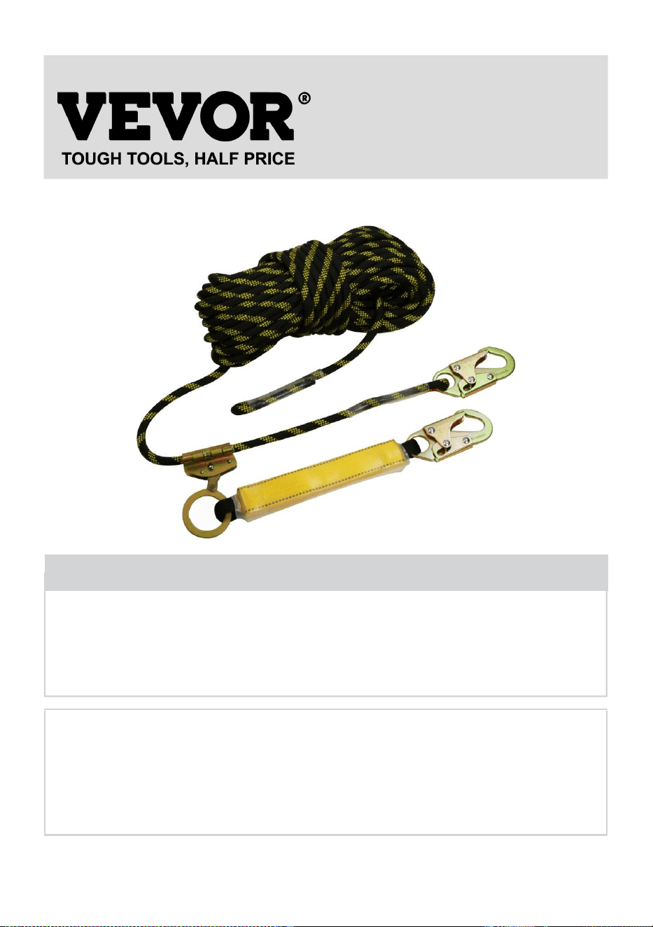
Fall Protection Lifelines
Trademark
Reference
standards
ANSI/ASSE Z359
"VEVOR. Fall Protection Lifelines" is an adjustable restraint device conforming to
standard ANSI/ASSE Z359.
This manual must be read and understood in its entirety . These instructions are
intended to meet the manufacturer instructions. The user must fully understand the
proper equipment use and limitations.
TECHNICAL SPECIFICATIONS
Model
ROPE-S-25
ROPE-S-50
ROPE-S-100
ROPE-Z-14-150
Main Material
Dacron
Color
Black, yellow
Net Weight
(kg)
2.06
3
4.7
7.6
line
supervisor(ft)
25
50
100
150
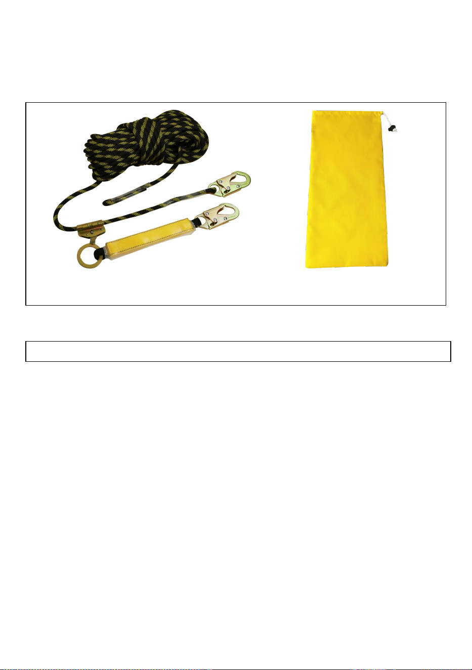
PACKAGE CONTENTS
Product instruction
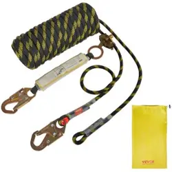
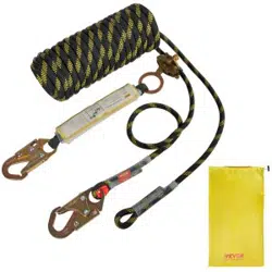
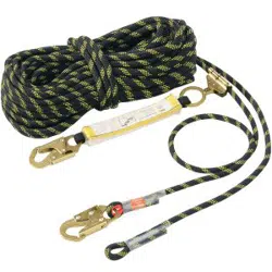
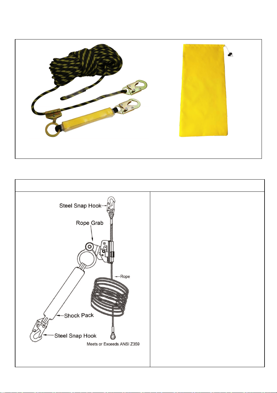
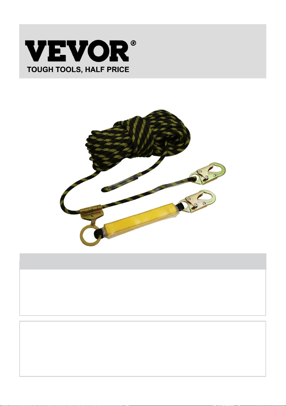
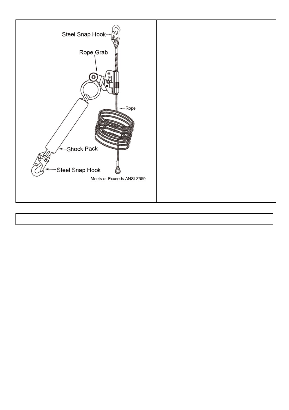
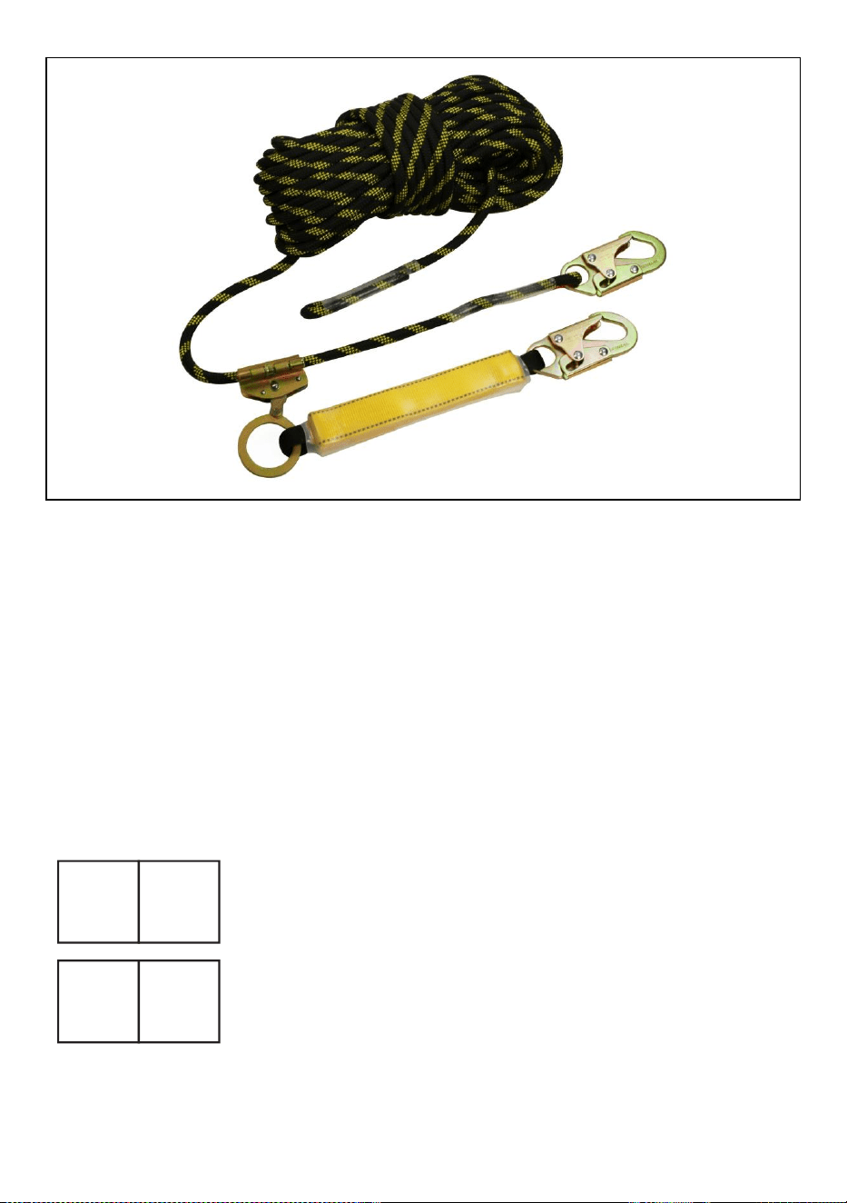
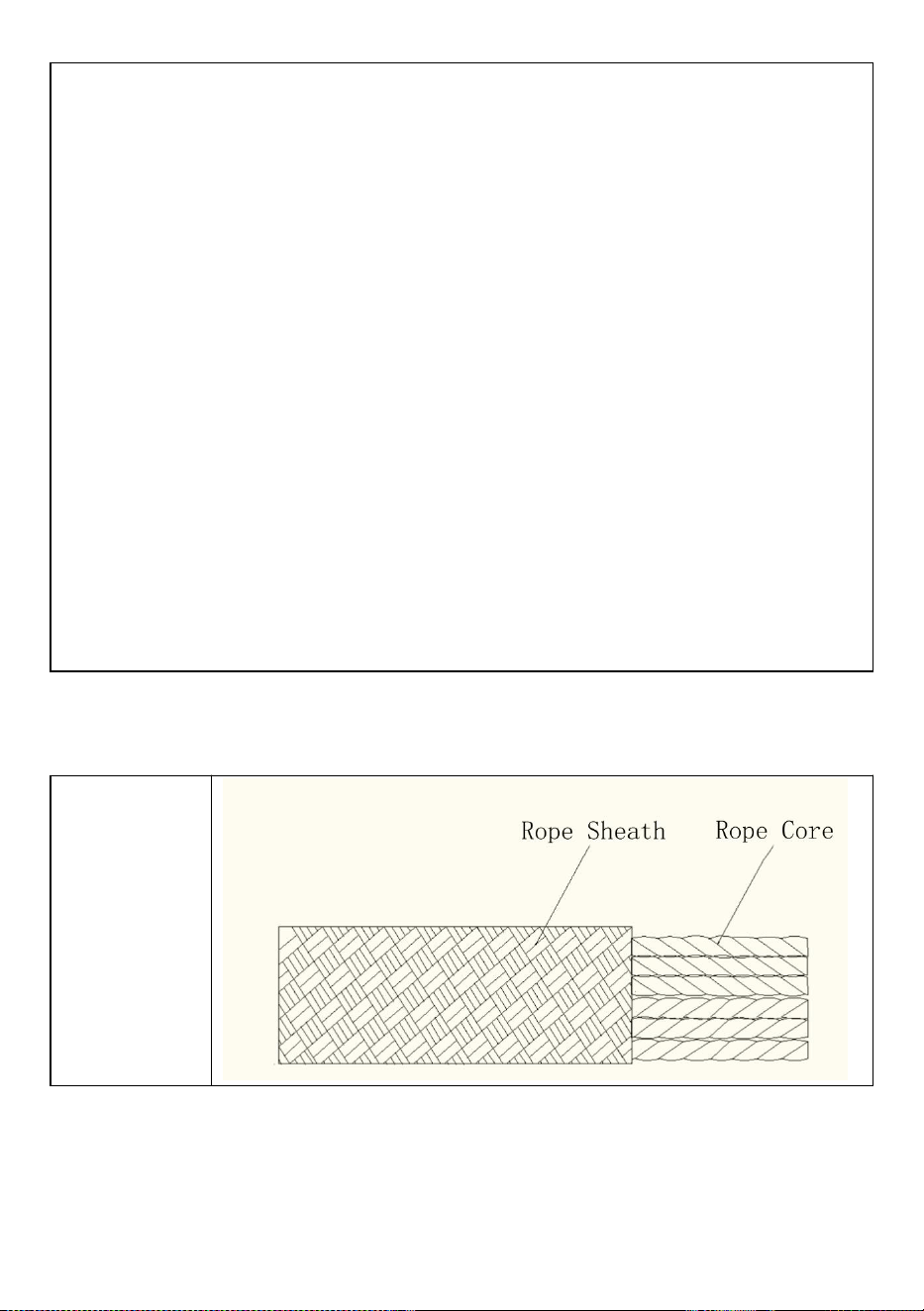
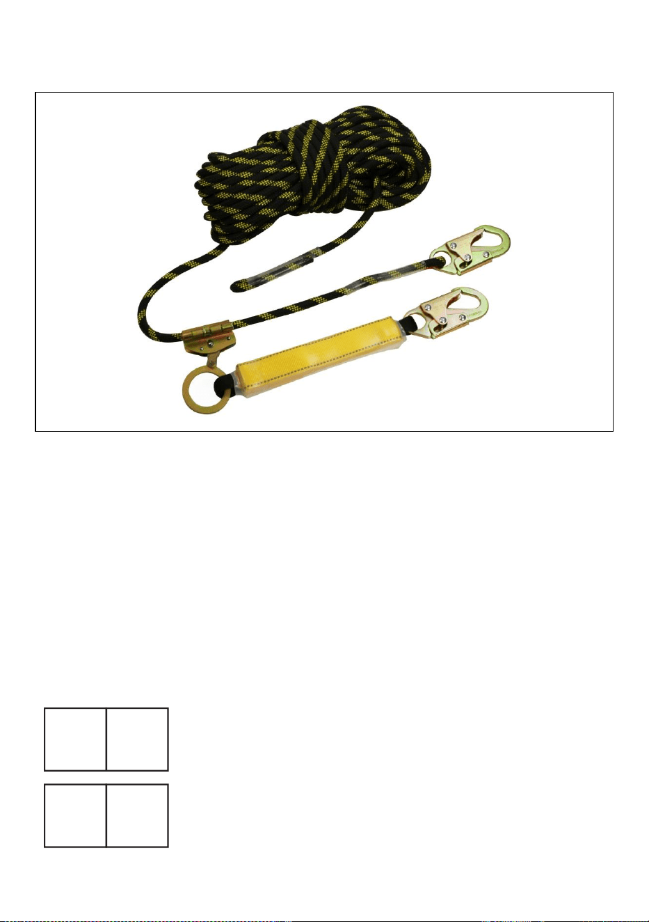
Fall Protection Lifelines construction
This lifeline is made up of
high-strength Polyester braided
rope. The diameter of the rope is
14mm. It is provided with a snap
hook spliced at one end and the
other end has a stop knot.
Fall Arrester with lanyard Connected
with a Shock Pack and has a Snap
Hook at the end. attachment to the
harness. The Fall Arrester is used
over the twisted rope lifeline.
×1
storage bag×1
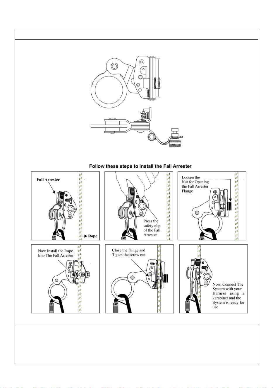
Fall Arrester Installation and Use
1) Eliminate all risk of lower end and termination. Either ensure Fall Arrester will
prevent the user from striking the next lower level and that there is always
adequate fall clearance, or that Fall Arrester will not reach the leading edge of any
fall hazard when used at its full length. NEVER tie a knot in a lifeline, except at the
extreme bottom of the lifeline in order to prevent Fall Arrest from detaching.
2) Eliminate or minimize all risks of swing falls.
3) Attach snap hook with integrated Shock Pack to compatible anchorage
connector.
4) Attach snap hook with integrated Fall Arrest to applicable harness D-ring.
5) To move along lifeline, compress and hold Fall Arrest handle. ALWAYS adjust
Fall Arrest to reduce slack in the system as much as possible. When attached to a
Fall Arrest and moving along work surface, ALWAYS do so by moving Fall Arrester
along rope, and NEVER by moving only the rope itself. For example, if moving
from a roof edge to the roof peak, engage handle of fall Arrester ad moves it up the
Fall Arrester while walking to peak. DO NOT move up to the roof peak by moving
Fall Arrester and keep Fall Arrest stationary; doing so can create free fall in excess
of levels permitted by the system.
6) To restrict Fall Arrest movement along lifeline, release Fall Arrest handle.
7) Fall Arrester comes with an anti-panic feature that automatically acts in case
the user holds the fall arrester and grasps it too tightly. However, care must be
taken that never grab a fall arrester in the event of a fall.
8) NEVER work above the Fall Arrester unless free fall is limited to 6 or less. One
connection per Fall Arrester. NEVER attempt to remove components from Fall
Arrester.
PERIODIC CHECKING OFPERSONAL PROTECTIVE EQUIPMENT
Description
PERIODIC CHECKING OF PERSONAL PROTECTIVE EQUIPMENT GENERAL REMARKS
Carrying out regular periodic checks (at intervals predetermined by the
manufacturer) is vital for ensuring the equipment's efficiency and durability and the
user's safety. The performance of regular periodic inspections is required by the
ASTM F887-16 standard and it is therefore mandatory only for some device
categories, whose instructions for use will expressly indicate such obligation.
Carrying out periodical controls doesn't relieve the user from the obligation to
perform the controls before and after each use, nor to require an extraordinary
periodic check, in case an outstanding event occurs (ex, a fall, even from a low
height, a change of user etc.), or in case of doubts about the correct functioning of
the device. Attention! Before first use, the owner/user of PPE must fill in the
"device identification sheet" when present in the user's instructions of the same,
Attention! The Inspector, after having carried out the periodic inspection, is
responsible for the proper functioning of a PPE. The check must be performed with
the highest accuracy, without haste, and after completing all the necessary steps.
Regular periodic checks must be carried out: if the previous use of the device is
unknown;at least every 12 months, with normal/standard use;in the presence of
anomalies found during the inspections before and after each use; except for
exceptions, whenever there is a change of user;filling the periodic inspection sheet
in,; Attention! The periodic inspection sheet also exists in the optimized version for
kits or systems of PPE. Attention! Provided that the minimum mandatory frequency
for the periodic inspection is 12 months, it can be increased (i.e. 3 months, 6
months etc.) according to the national regulations in force or the frequency,
intensity and method of use (i.e. heavy use, use in a marine environment,
corrosive atmospheres etc.).
The periodic inspection sheet must be filled out: following the specific procedure
for each type of device. climbing technology.com);consulting the photographic
material available, where present;consulting the instructions for use of the
device;examining the device in a suitable, tidy and well-lit environment. The
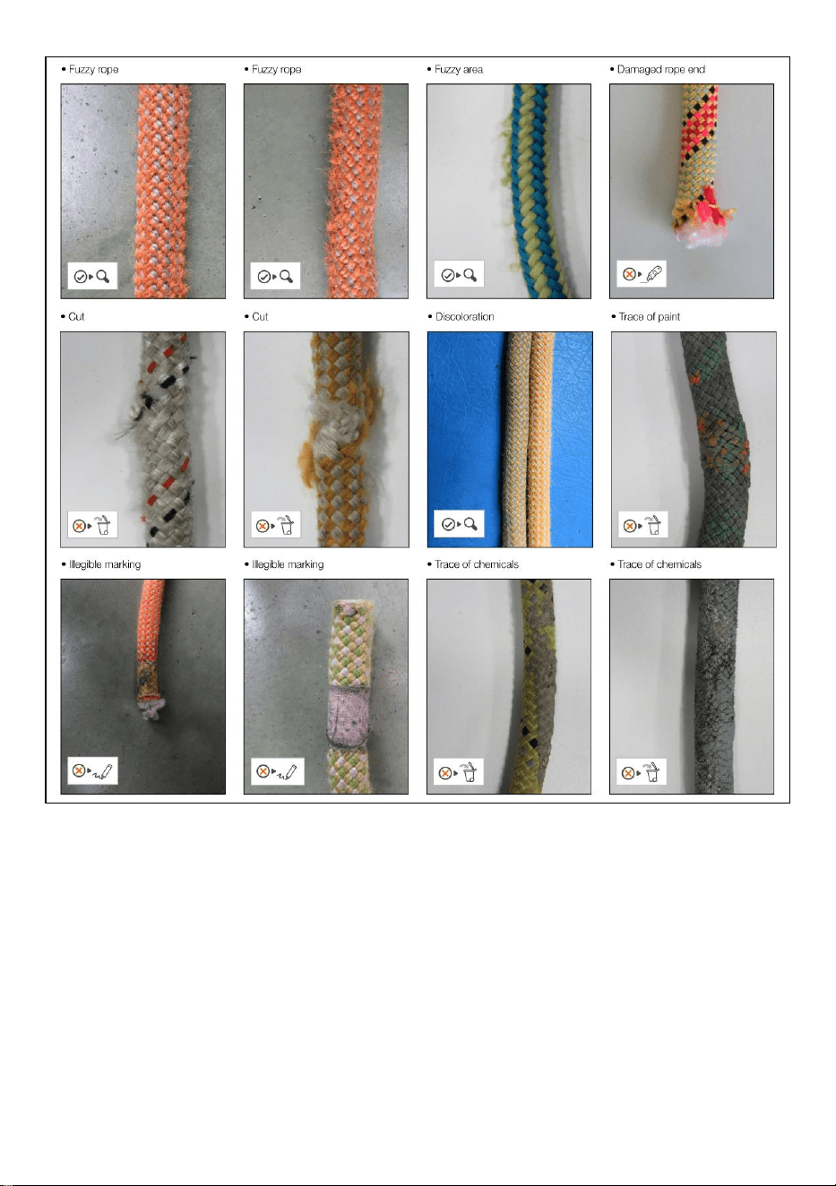
photographic material at the end of the procedures is accompanied by an
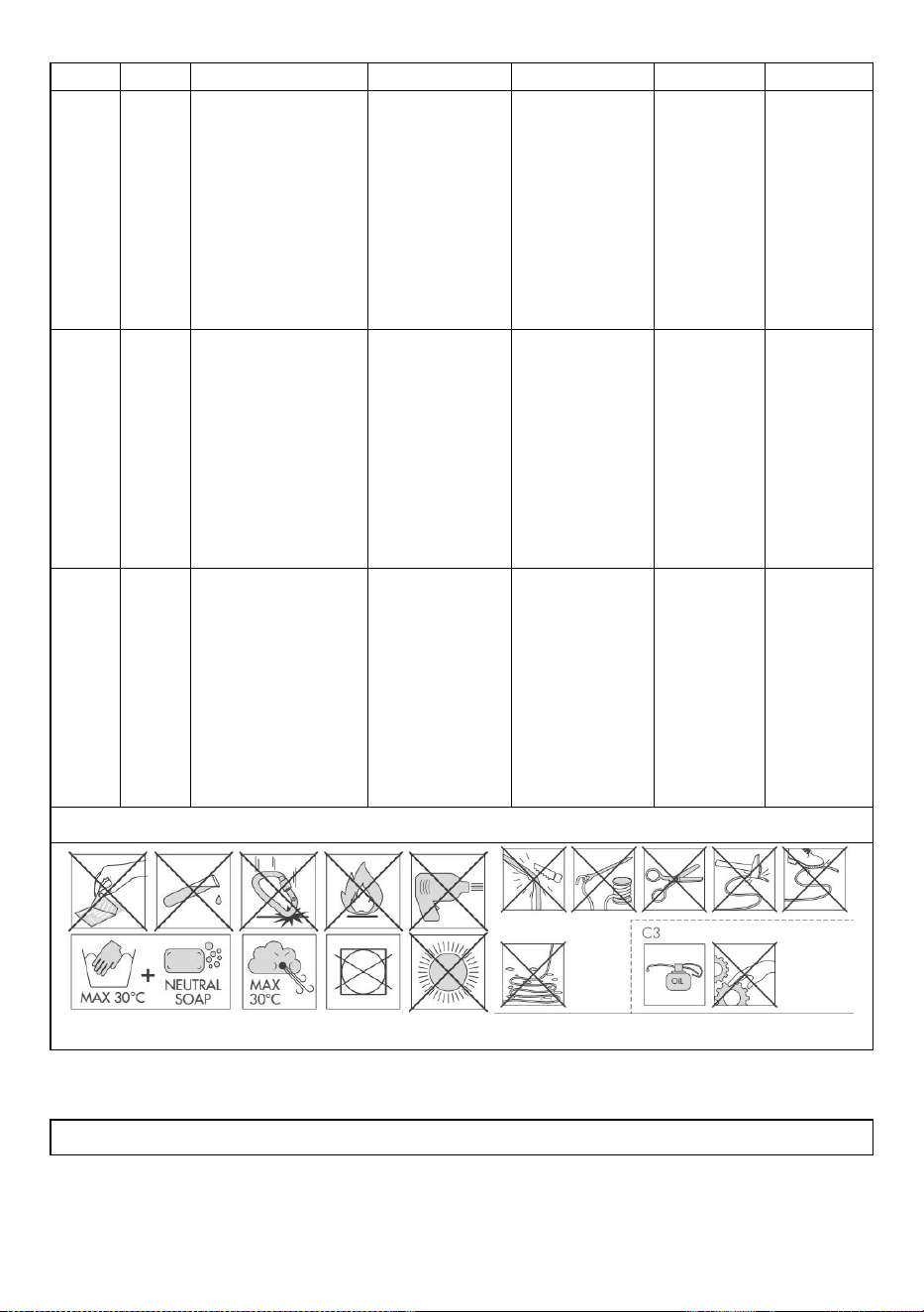
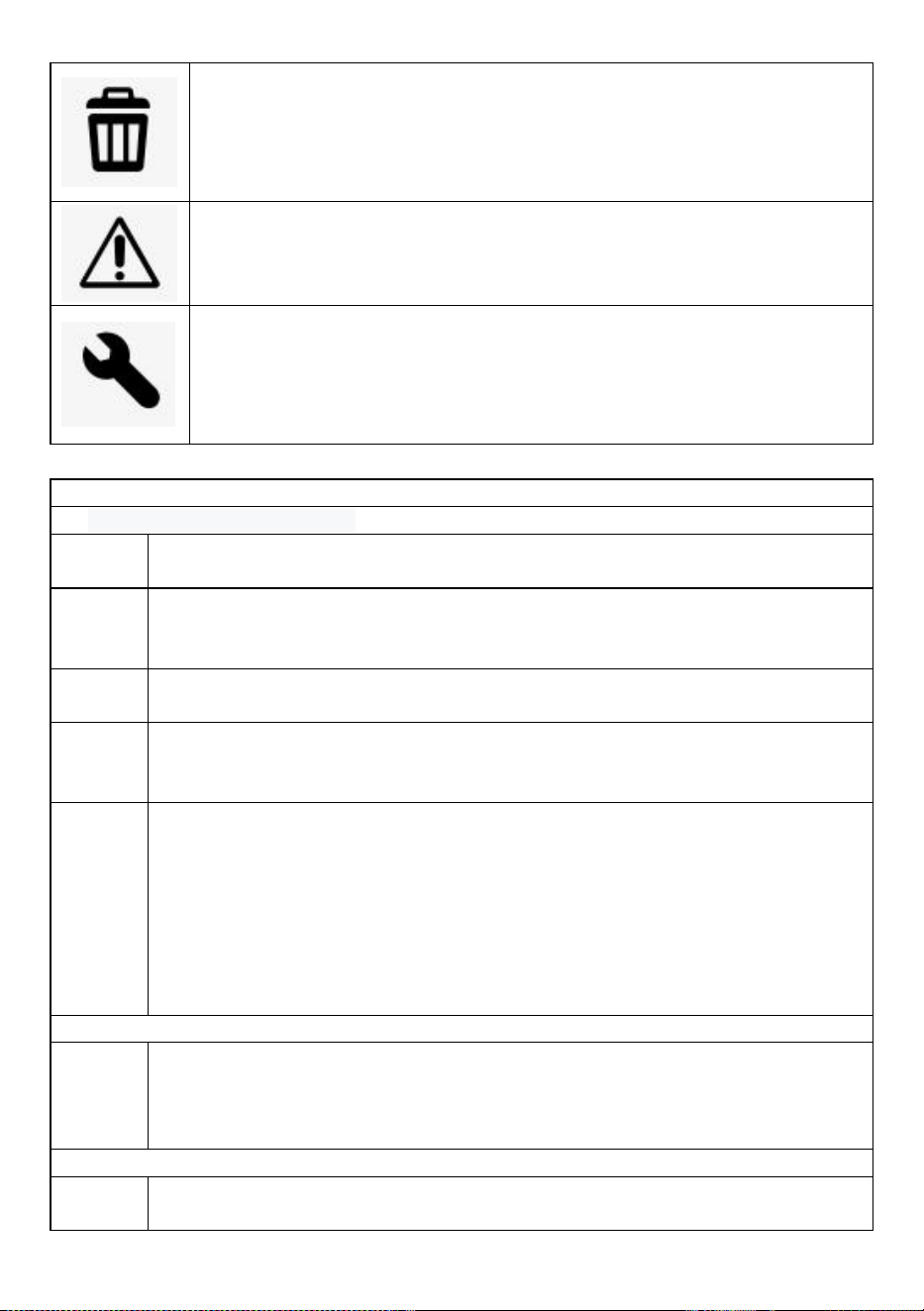
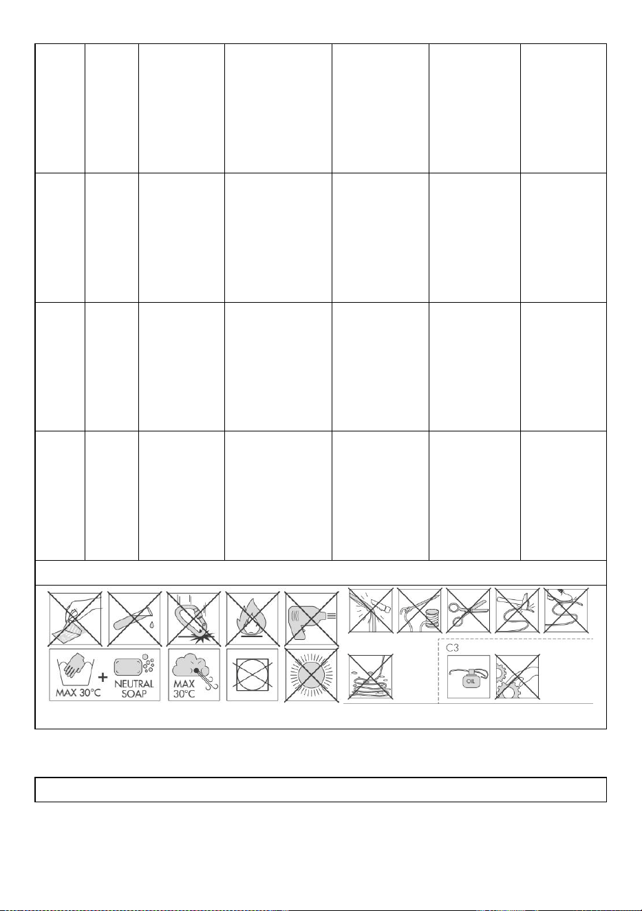
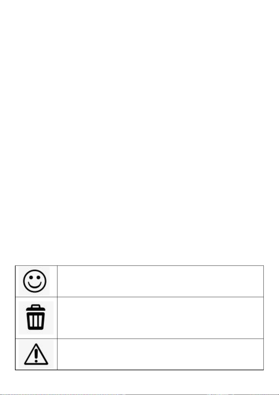
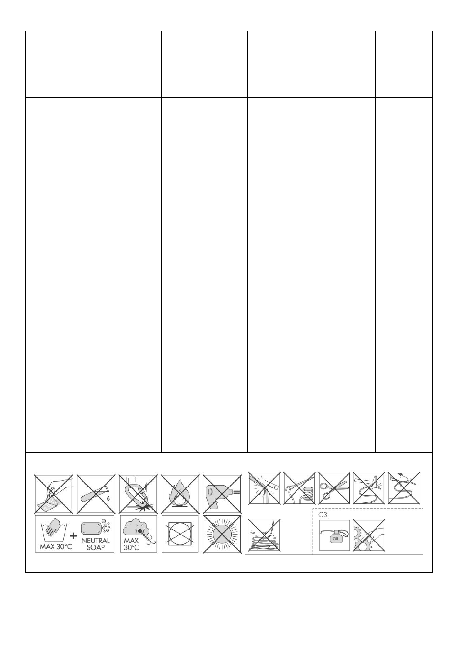
explication caption and by the following symbols:
The device is in good condition or has only minor damages: it is
therefore suitable for use.
The device has medium/major damages that affect its primary
functions and, as a consequence, must be discarded.
The device has defects that can be solved through lubrication or
cleaning. If such defects are not solved, the device must be
discarded.
The device has defects.
DEVICE PERIODIC CHECK SHEET
1) Known product history
1.1
Check the existence and the readability of the marking details
。
1.2
Check that device has not exceeded the storage and/or in-use lifetime,
as stated in the specific instructions for use.
1.3
Check that the device is intact and no parts are missing (check against a
new product).
1.4
Check that the device has not been modified outside the factory or
serviced in a non-approved centre (check against a new product).
1.5
Any PPE showing unexpected degradation should be quarantined,
pending a detailed inspection. The user should:
- Provide precise information on the usage conditions.
- Report any exceptional event regarding his PPE. (Examples: fall or fall
arrest, use or storage at extreme temperatures, modification outside
manufacturer's facilities...).
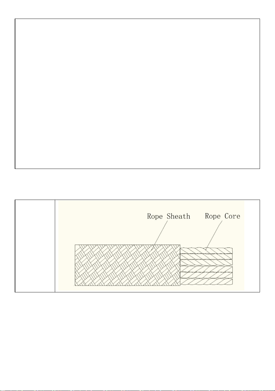
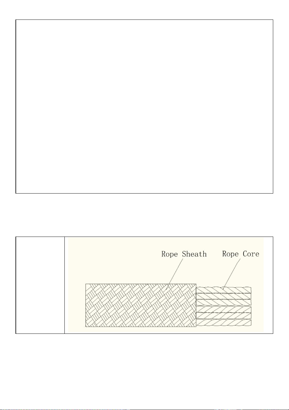
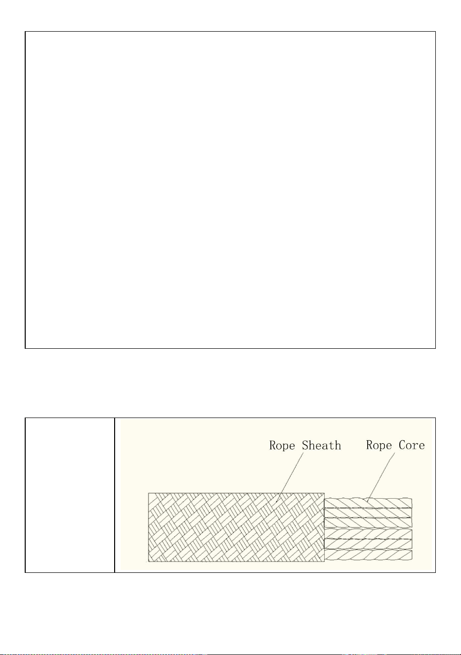
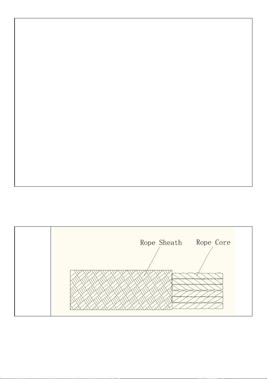
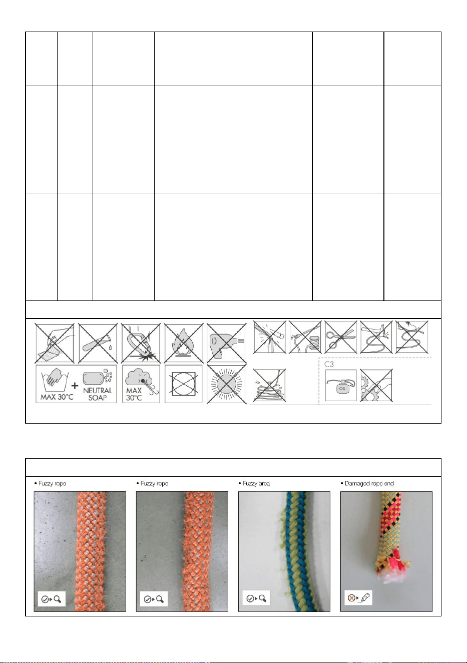
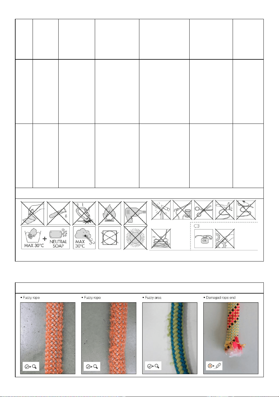
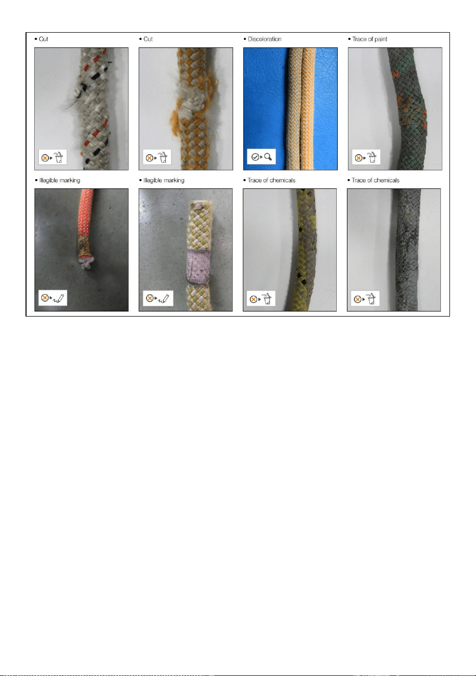
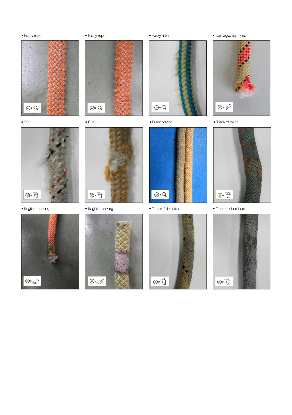
2) Checking the condition of the sheath
2.1
Check the condition of the sheath over the full length of the rope. Make
sure there are nocuts, burns, frayed strands, fuzzy areas, or signs of
chemicals...
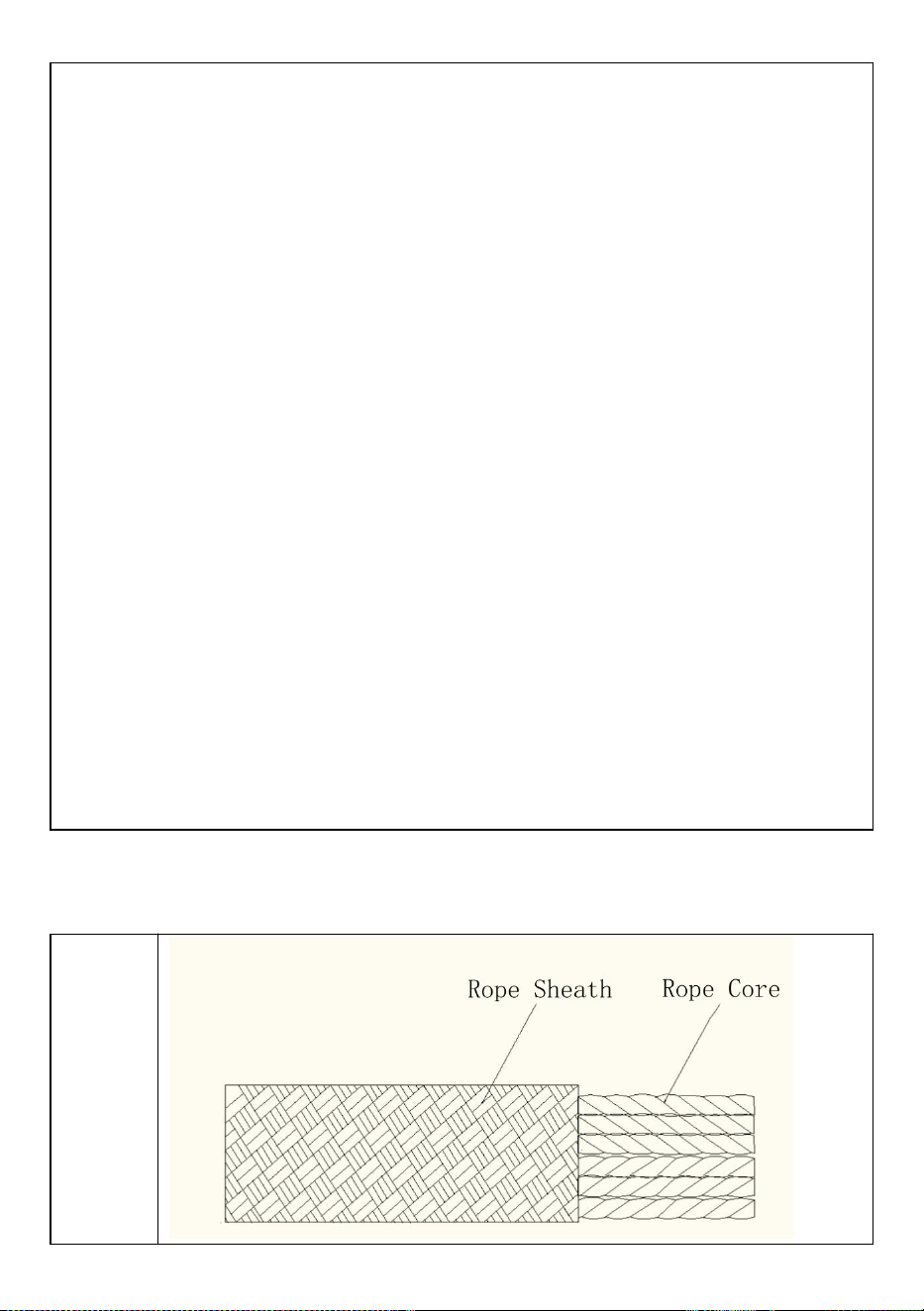
3) Checking the condition of the core
3.1
Do a tactile inspection of the core over the full length of the rope, as
indicated in the drawing. This allows you to detect areas where the core
is damaged (hard spots, swelling, soft or crushed areas...).
4) Checking the condition of the core
4.1
To check the length of your rope, follow the steps below:1. Completely
uncoil the rope.2. Check the middle mark of the rope. There is a simple
way to find the middle of the rope: hold the two rope ends together, then
slide the two strands simultaneously through your hands until the middle
of the rope is reached. If your rope has a middle mark, check it for
accuracy. If the mark is OK, go to the next step. If the mark is not in the
right place or if there is no middle mark, place a piece of adhesive tape
at the rope's midpoint to help measure its length.
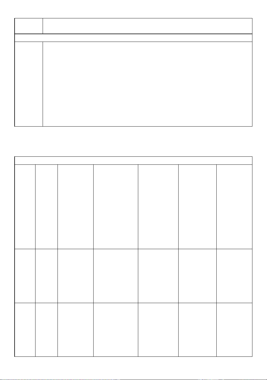
DEVICE PERIODIC CHECK SHEET
No.
Date
Reasonfor
check
Name and
signature of
the person
responsible
for
checking.
Notes (defects
found, repairs
performed or
otherrelevant
information)
Check
results
Date of
next
check
1
□Periodic
□Additional
□Device fit
for use.
□Device
unfit for use
2
□Periodic
□Additional
□Device fit
for use.
□Device
unfit for use
3
□Periodic
□Additional
□Device fit
for use.
□Device
unfit for use
4
□Periodic
□Additional
□Device fit
for use.
□Device
unfit for use
5
□Periodic
□Additional
□Device fit
for use.
□Device
unfit for use
6
□Periodic
□Additional
□Device fit
for use.
□Device
unfit for use
WARNINGS
PHOTO APPENDIX
COMPLETION

Address: Shuangchenglu 803nong11hao1602A-1609shi, baoshanqu,
shanghai 200000 CN.
Imported to AUS: SIHAO PTY LTD, 1 ROKEVA STREETEASTWOOD
NSW 2122 Australia
Imported to USA: Sanven Technology Ltd., Suite 250, 9166 Anaheim
Place, Rancho Cucamonga, CA 91730
REP
EC
E-CrossStu GmbH
Mainzer Landstr.69, 60329 Frankfurt am Main.
REP
UK
YH CONSULTING LIMITED.
C/O YH Consulting Limited Office 147, Centurion House,
London Road, Staines-upon-Thames, Surrey, TW18 4AX


Technique Assistance et certificat de garantie électronique
www.vevor.com/support
LIGNES DE VIE DE PROTECTION CONTRE
LES CHUTES
MANUEL DE L' UTILISATEUR
N° DE MODÈLE : CORDE-S-25, CORDE-S-50,
CORDE-S-100, CORDE-Z-14-150
We continue to be committed to provide you tools with competitive price.
"Save Half", "Half Price" or any other similar expressions used by us only represents an
estimate of savings you might benefit from buying certain tools with us compared to the major
top brands and does not necessarily mean to cover all categories of tools offered by us. You
are kindly reminded to verify carefully when you are placing an order with us if you are
actually saving half in comparison with the top major brands.
N° DE MODÈLE : CORDE-S-25 , CORDE-S-50 , CORDE-S-100 ,
CORDE-Z-14-150
Have product questions? Need technical support? Please feel free to
contact us:
Technical Support and E-Warranty Certificate
www.vevor.com/support
NEED HELP? CONTACT US!
This is the original instruction, please read all manual instructions
carefully before operating. VEVOR reserves a clear interpretation of our
user manual. The appearance of the product shall be subject to the
product you received. Please forgive us that we won't inform you again if
there are any technology or software updates on our product.
Fall Protection Lifelines

AVERTISSEMENT:
Veuillez lire attentivement ce manuel avant d'utiliser le produit. Ne
pas le faire pourrait entraîner des blessures graves. CONSERVEZ CE
MANUEL
INFORMATIONS GÉNÉRALES
Lignes de vie de protection contre les chutes
Marque
déposée
Normes de
référence
ANSI/ASS Z 359
"VEVOR. Fall Protection Lifelines " est un dispositif de retenue réglable conforme
à la norme ANSI/ASSE Z359.
Ce manuel doit être lu et compris dans son intégralité. Ces instructions sont
destinées à répondre aux instructions du fabricant. L'utilisateur doit parfaitement
comprendre l'utilisation appropriée de l'équipement et ses limites.
SPÉCIFICATIONS TECHNIQUES
Modèle
CORDE-S-2
5
CORDE-S-50
CORDE-S-10
0
CORDE-Z-14-1
50
Matériau
principal
Dacron
Couleur
Noir jaune
Poids net /
kg)
2.06
3
4.7
7.6
superviseur
de ligne (pi)
25
50
100
150
CONTENU DU COLIS
Instructions du produit
Construction de lignes de vie de protection contre les chutes
×1
storage bag×1

Cette ligne de vie est composée
d'une corde tressée en polyester
haute résistance. Le diamètre de la
corde est de 14 mm. Il est muni d'un
mousqueton épissé à une extrémité
et l'autre extrémité est munie d'un
nœud d'arrêt.
Antichute avec longe Connecté à un
Shock Pack et doté d'un
mousqueton à l'extrémité. fixation au
harnais. L'antichute est utilisé sur la
ligne de vie en corde torsadée.
Installation et utilisation de l'antichute

9) Éliminez tout risque de bas de gamme et de résiliation. Soit vous assurez que
l'antichute empêchera l'utilisateur de heurter le niveau inférieur suivant et qu'il y a
toujours un dégagement de chute adéquat, soit que l'antichute n'atteindra pas le
bord d'attaque d'un risque de chute lorsqu'il est utilisé sur toute sa longueur. NE
JAMAIS faire de nœud dans une ligne de vie, sauf à l'extrême bas de la ligne de
vie afin d'éviter que l'antichute ne se détache.
10) Éliminez ou minimisez tous les risques de chutes pivotantes.
11) Fixez le mousqueton avec Shock Pack intégré au connecteur d’ancrage
compatible.
12) Fixez le mousqueton avec dispositif antichute intégré à l'anneau en D du
harnais applicable.
13) Pour vous déplacer le long de la ligne de vie, comprimez et maintenez la
poignée antichute. TOUJOURS régler l’antichute pour réduire autant que possible
le jeu du système. Lorsqu'il est fixé à un antichute et se déplace le long de la
surface de travail, faites-le TOUJOURS en déplaçant l'antichute le long de la
corde, et JAMAIS en déplaçant uniquement la corde elle-même. Par exemple, si
vous vous déplacez d'un bord de toit au sommet du toit, engagez la poignée de
l'antichute et déplacez-le vers le haut de l'antichute tout en marchant jusqu'au
sommet. NE PAS monter jusqu'au sommet du toit en déplaçant l'antichute et
maintenir l'antichute stationnaire ; cela peut créer une chute libre au-delà des
niveaux autorisés par le système.
14) Pour restreindre le mouvement de l'antichute le long de la ligne de vie,
relâchez la poignée de l'antichute.
15) Fall Arrester est doté d'une fonction anti-panique qui agit automatiquement si
l'utilisateur tient l'antichute et le saisit trop fort. Il faut cependant veiller à ne jamais
saisir un antichute en cas de chute.
16) NE JAMAIS travailler au-dessus de l'antichute à moins que la chute libre ne
soit limitée à 6 ou moins. Une connexion par antichute. N'essayez JAMAIS de
retirer des composants de l'antichute .
CONTRÔLE PÉRIODIQUE DES ÉQUIPEMENTS DE PROTECTION
INDIVIDUELLE
Description
CONTRÔLE PÉRIODIQUE DES ÉQUIPEMENTS DE PROTECTION INDIVIDUELLE REMARQUES
GÉNÉRALES
La réalisation de contrôles périodiques réguliers (à intervalles prédéterminés par
le fabricant) est essentielle pour garantir l'efficacité et la durabilité de l'équipement
ainsi que la sécurité de l'utilisateur. La réalisation d'inspections périodiques

régulières est requise par la norme ASTM F887-16 et elle n'est donc obligatoire
que pour certaines catégories d'appareils, dont les instructions d'utilisation
indiqueront expressément cette obligation. La réalisation de contrôles périodiques
ne dispense pas l'utilisateur de l'obligation d'effectuer les contrôles avant et après
chaque utilisation, ni d'exiger un contrôle périodique extraordinaire, en cas
d'événement exceptionnel (par exemple, une chute, même de faible hauteur, une
changement d'utilisateur etc.), ou en cas de doute sur le bon fonctionnement de
l'appareil. Attention! Avant la première utilisation, le propriétaire/utilisateur de l'EPI
doit remplir la « fiche d'identification de l'appareil » lorsqu'elle est présente dans la
notice d'utilisation de celui-ci, Attention ! L'Inspecteur, après avoir procédé au
contrôle périodique, est responsable du bon fonctionnement d'un EPI. Le contrôle
doit être effectué avec la plus grande précision, sans hâte et après avoir effectué
toutes les étapes nécessaires.
Des contrôles périodiques réguliers doivent être effectués : si l'utilisation
antérieure de l'appareil est inconnue ; au moins tous les 12 mois, en cas
d'utilisation normale/standard ; en présence d'anomalies constatées lors des
inspections avant et après chaque utilisation ; sauf exception, à chaque
changement d'utilisateur;remplir la fiche de contrôle périodique,; Attention! La
fiche de contrôle périodique existe également en version optimisée pour les kits ou
systèmes d'EPI. Attention! A condition que la fréquence minimale obligatoire du
contrôle périodique soit de 12 mois, elle peut être augmentée (c'est-à-dire 3 mois,
6 mois etc.) en fonction de la réglementation nationale en vigueur ou de la
fréquence, de l'intensité et du mode d'utilisation (c'est-à-dire usage intensif, usage
en milieu marin, atmosphères corrosives etc.).
La fiche de contrôle périodique doit être remplie : selon la procédure spécifique à
chaque type d'appareil. Climbing Technology.com) ; consulter le matériel
photographique disponible, le cas échéant ; consulter la notice d'utilisation de
l'appareil ; examiner l'appareil dans un environnement adapté, rangé et bien
éclairé. Le matériel photographique à la fin des procédures est accompagné d'une
légende explicative et des symboles suivants :
L'appareil est en bon état ou ne présente que des dommages
mineurs : il est donc apte à l'utilisation.
L'appareil présente des dommages moyens/majeurs qui affectent
ses fonctions principales et, par conséquent, doit être mis au rebut.

L'appareil présente des défauts qui peuvent être résolus par
lubrification ou nettoyage. Si ces défauts ne sont pas résolus,
l'appareil doit être mis au rebut.
L'appareil présente des défauts.
FICHE DE CONTRÔLE PÉRIODIQUE DE L'APPAREIL
1) Historique connu du produit
1.1
Vérifiez l'existence et la lisibilité des détails du marquage.
1.2
Vérifiez que l'appareil n'a pas dépassé la durée de vie de stockage et/ou
d'utilisation, comme indiqué dans les instructions d'utilisation
spécifiques.
1.3
Vérifiez que l'appareil est intact et qu'aucune pièce ne manque (à
comparer avec un produit neuf).
1.4
Vérifiez que l'appareil n'a pas été modifié en dehors de l'usine ou réparé
dans un centre non agréé (vérifiez par rapport à un produit neuf).
1,5
Tout EPI présentant une dégradation inattendue doit être mis en
quarantaine, en attendant une inspection détaillée. L'utilisateur doit :
- Fournir des informations précises sur les conditions d'utilisation.
- Signaler tout événement exceptionnel concernant son EPI.
(Exemples : chute ou antichute, utilisation ou stockage à des
températures extrêmes, modification hors des installations du
fabricant...).
2) Vérification de l'état de la gaine
2.1
Vérifier l'état de la gaine sur toute la longueur de la corde. Assurez-vous
qu'il n'y a pas de coupures, de brûlures, de mèches effilochées, de
zones floues ou de signes de produits chimiques...
3) Vérification de l'état du noyau
3.1
Effectuer une inspection tactile de l'âme sur toute la longueur de la
corde, comme indiqué sur le dessin. Cela permet de détecter les zones
où le noyau est endommagé (points durs, gonflements, zones molles ou
écrasées...).
4) Vérification de l'état du noyau
4.1
Pour vérifier la longueur de votre corde, suivez les étapes ci-dessous :1.
Déroulez complètement la corde.2. Vérifiez la marque centrale de la
corde. Il existe un moyen simple de trouver le milieu de la corde :
maintenez les deux extrémités de la corde ensemble, puis faites glisser
simultanément les deux brins entre vos mains jusqu'à atteindre le milieu
de la corde. Si votre corde a une marque centrale, vérifiez-en

l'exactitude. Si la marque est OK, passez à l'étape suivante. Si le repère
n'est pas au bon endroit ou s'il n'y a pas de repère central, placez un
morceau de ruban adhésif au milieu de la corde pour vous aider à
mesurer sa longueur.
FICHE DE CONTRÔLE PÉRIODIQUE DE L'APPAREIL
Non
.
Dat
e
Motif du
contrôle
Nom et
signature
de la
personne
responsabl
e du
contrôle.
Notes
(défauts
constatés,
réparations
effectuées
ou autres
information
s
pertinentes)
Vérifier
les
résultats
Date du
prochai
n
contrôle
1
□ Périodique
□
Supplémentair
e
□
Appareil
apte à
l'emploi.
□
Appareil
impropr
e à
l'usage
2
□ Périodique
□
Supplémentair
e
□
Appareil
apte à
l'emploi.
□
Appareil
impropr
e à
l'usage
3
□ Périodique
□
Supplémentair
e
□
Appareil
apte à
l'emploi.
□
Appareil
impropr
e à
l'usage
4
□ Périodique
□
Supplémentair
e
□
Appareil
apte à
l'emploi.
□
Appareil
impropr
e à
l'usage
5
□ Périodique
□
Supplémentair
e
□
Appareil
apte à
l'emploi.
□
Appareil
impropr
e à
l'usage
6
□ Périodique
□
Supplémentair
e
□
Appareil
apte à
l'emploi.
□
Appareil
impropr
e à
l'usage
AVERTISSEMENTS
ANNEXE PHOTOS

ACHÈVEMENT

Adresse : Shuangchenglu 803nong11hao1602A-1609shi, baoshanqu,
Shanghai 200000 CN.
Importé en Australie : SIHAO PTY LTD, 1 ROKEVA STREETESTWOOD
NSW 2122 Australie
Importé aux États-Unis : Sanven Technology Ltd., Suite 250, 9166
Anaheim Place, Rancho Cucamonga, CA 91730
REP
EC
E-CrossStu GmbH
Mainzer Landstr.69, 60329 Frankfurt am Main.
REP
UK
YH CONSULTING LIMITED.
C/O YH Consulting Limited Office 147, Centurion House,
London Road, Staines-upon-Thames, Surrey, TW18 4AX


Technisch Support und E-Garantie-Zertifikat
www.vevor.com/support
ABSTURZSICHERUNGEN
BENUTZERHANDBUCH
MODELL NR.: ROPE-S-25, ROPE-S-50,
SEIL-S-100, SEIL-Z-14-150
We continue to be committed to provide you tools with competitive price.
"Save Half", "Half Price" or any other similar expressions used by us only represents an
estimate of savings you might benefit from buying certain tools with us compared to the major
top brands and does not necessarily mean to cover all categories of tools offered by us. You
are kindly reminded to verify carefully when you are placing an order with us if you are
actually saving half in comparison with the top major brands.
MODELLNR.: ROPE-S-25 , ROPE-S-50 , ROPE-S-100 , ROPE-Z-14-150
Have product questions? Need technical support? Please feel free to
contact us:
Technical Support and E-Warranty Certificate
www.vevor.com/support
NEED HELP? CONTACT US!
This is the original instruction, please read all manual instructions
carefully before operating. VEVOR reserves a clear interpretation of our
user manual. The appearance of the product shall be subject to the
product you received. Please forgive us that we won't inform you again if
there are any technology or software updates on our product.
Fall Protection Lifelines

WARNUNG:
Bitte lesen Sie dieses Handbuch sorgfältig durch, bevor Sie das
Produkt verwenden. Andernfalls kann es zu schweren Verletzungen
kommen. BEWAHREN SIE DIESES HANDBUCH AUF
ALLGEMEINE INFORMATIONEN
Absturzsicherungen
Warenzeichen
Referenzstandards
ANSI/ASSE Z 359
„VEVOR. Fall Protection Lifelines “ ist ein einstellbares Rückhaltegerät
entsprechend der Norm ANSI/ASSE Z359.
Dieses Handbuch muss vollständig gelesen und verstanden werden. Diese
Anweisungen sollen die Anweisungen des Herstellers erfüllen. Der Benutzer muss
die ordnungsgemäße Verwendung und die Einschränkungen der Ausrüstung
vollständig verstehen.
TECHNISCHE SPEZIFIKATIONEN
Modell
Seil-S-25
Seil-S-50
Seil-S-100
SEIL-Z-14-150
Hauptmateria
l
Dacron
Farbe
Schwarz Gelb
Nettogewicht
/ kg)
2.06
3
4.7
7.6
Linienleiter
(Vollzeit)
25
50
100
150

PACKUNGSINHALT
Produktanleitung
Absturzsicherung Rettungsleinen Bau
Diese Rettungsleine besteht aus
hochfestem geflochtenem
Polyesterseil. Der Durchmesser des
Seils beträgt 14 mm. An einem Ende
ist ein Karabinerhaken eingespleißt,
am anderen Ende befindet sich ein
Stopperknoten.
Auffanggerät mit Verbindungsmittel,
das mit einem Shock Pack
verbunden ist und am Ende einen
Karabinerhaken hat. Befestigung am
Gurt. Das Auffanggerät wird über der
gedrehten Seilsicherung verwendet.
×1
storage bag×1

Installation und Verwendung von Fallschutzgeräten

17) Beseitigen Sie alle Risiken eines unteren Endes und einer Beendigung.
Stellen Sie entweder sicher, dass der Fallschutz den Benutzer daran hindert, die
nächste Ebene zu erreichen, und dass immer ausreichend Fallfreiheit vorhanden
ist, oder dass der Fallschutz bei voller Verwendung nicht die Vorderkante einer
Sturzgefahr erreicht. Machen Sie NIEMALS einen Knoten in eine Rettungsleine,
außer am äußersten Ende der Rettungsleine, um zu verhindern, dass sich der
Fallschutz löst.
18) Beseitigen oder minimieren Sie sämtliche Risiken von Schwingstürzen.
19) Befestigen Sie den Karabinerhaken mit integriertem Shock Pack am
kompatiblen Verankerungsverbinder.
20) Befestigen Sie den Karabinerhaken mit integrierter Absturzsicherung am
entsprechenden D-Ring des Auffanggurts.
21) Um sich entlang der Rettungsleine zu bewegen, drücken Sie den Griff des
Fallschutzes zusammen und halten Sie ihn fest. Passen Sie den Fallschutz
IMMER an, um das Spiel im System so weit wie möglich zu reduzieren. Wenn Sie
an einem Fallschutz befestigt sind und sich entlang der Arbeitsfläche bewegen,
tun Sie dies IMMER, indem Sie den Fallschutz entlang des Seils bewegen und
NIEMALS nur das Seil selbst. Wenn Sie sich beispielsweise von einer Dachkante
zum Dachfirst bewegen, greifen Sie den Griff des Fallschutzes und bewegen Sie
ihn am Fallschutz nach oben, während Sie zum Dachfirst gehen. Bewegen Sie
sich NICHT zum Dachfirst, indem Sie den Fallschutz bewegen und den Fallschutz
stationär halten; dadurch kann ein freier Fall entstehen, der die vom System
zugelassenen Höhen überschreitet.
22) Um die Bewegung des Absturzschutzes entlang der Rettungsleine
einzuschränken, lassen Sie den Absturzschutzgriff los.
23) Der Fallschutz ist mit einer Anti-Panik-Funktion ausgestattet, die automatisch
eingreift, wenn der Benutzer den Fallschutz zu fest hält. Es muss jedoch darauf
geachtet werden, dass man im Falle eines Sturzes niemals den Fallschutz
festhält.
24) Arbeiten Sie NIEMALS über dem Fallschutz, es sei denn, der freie Fall ist auf
6 oder weniger begrenzt. Eine Verbindung pro Fallschutz. Versuchen Sie
NIEMALS, Komponenten vom Fallschutz zu entfernen .
REGELMÄSSIGE ÜBERPRÜFUNG DER PERSÖNLICHEN
SCHUTZAUSRÜSTUNG
Beschreibung
REGELMÄSSIGE ÜBERPRÜFUNG DER PERSÖNLICHEN SCHUTZAUSRÜSTUNG ALLGEMEINE
BEMERKUNGEN

Die Durchführung regelmäßiger periodischer Kontrollen (in vom Hersteller
festgelegten Abständen) ist für die Gewährleistung der Effizienz und Haltbarkeit
der Ausrüstung und der Sicherheit des Benutzers unerlässlich. Die Durchführung
regelmäßiger periodischer Kontrollen wird durch die Norm ASTM F887-16
gefordert und ist daher nur für einige Gerätekategorien obligatorisch, deren
Gebrauchsanweisung ausdrücklich auf diese Verpflichtung hinweist. Die
Durchführung periodischer Kontrollen entbindet den Benutzer nicht von der
Verpflichtung, die Kontrollen vor und nach jedem Gebrauch durchzuführen, noch
von der Verpflichtung, eine außerordentliche periodische Kontrolle zu verlangen,
falls ein außergewöhnliches Ereignis eintritt (z. B. ein Sturz, auch aus geringer
Höhe, ein Benutzerwechsel usw.) oder falls Zweifel an der korrekten Funktion des
Geräts bestehen. Achtung! Vor dem ersten Gebrauch muss der Besitzer/Benutzer
der PSA das „Geräteidentifikationsblatt“ ausfüllen, wenn es in der
Gebrauchsanweisung derselben vorhanden ist. Achtung! Der Inspektor ist nach
der Durchführung der periodischen Kontrolle für die ordnungsgemäße Funktion
einer PSA verantwortlich. Die Kontrolle muss mit höchster Genauigkeit, ohne Eile
und nach Abschluss aller erforderlichen Schritte durchgeführt werden.
Es müssen regelmäßige periodische Kontrollen durchgeführt werden: wenn der
vorherige Einsatz des Geräts nicht bekannt ist; mindestens alle 12 Monate, bei
normalem/standardmäßigem Einsatz; bei Anomalien, die bei den Kontrollen vor
und nach jedem Einsatz festgestellt werden; außer in Ausnahmefällen, bei jedem
Benutzerwechsel; Ausfüllen des regelmäßigen Kontrollblatts in; Achtung! Das
regelmäßigen Kontrollblatt ist auch in der optimierten Version für Bausätze oder
Systeme von PSA vorhanden. Achtung! Sofern die vorgeschriebene
Mindesthäufigkeit für die regelmäßige Kontrolle 12 Monate beträgt, kann sie je
nach geltenden nationalen Vorschriften oder Häufigkeit, Intensität und Art des
Einsatzes (z. B. starke Beanspruchung, Einsatz in Meeresumwelt, korrosiver
Atmosphäre usw.) erhöht werden (z. B. 3 Monate, 6 Monate usw.).
Das regelmäßige Prüfblatt muss wie folgt ausgefüllt werden: Befolgen Sie das für
jeden Gerätetyp spezifische Verfahren. climbing technology.com); konsultieren Sie
das verfügbare Fotomaterial, sofern vorhanden; konsultieren Sie die
Gebrauchsanweisung des Geräts; prüfen Sie das Gerät in einer geeigneten,
aufgeräumten und gut beleuchteten Umgebung. Das Fotomaterial am Ende der
Verfahren wird von einer erklärenden Bildunterschrift und den folgenden
Symbolen begleitet:
Das Gerät ist in einem guten Zustand oder weist lediglich
geringfügige Beschädigungen auf und ist somit zur Nutzung
geeignet.
Das Gerät weist mittlere/schwere Schäden auf, die seine
Hauptfunktionen beeinträchtigen und muss daher entsorgt werden.
Das Gerät weist Mängel auf, die durch Schmierung oder Reinigung
behoben werden können. Wenn solche Mängel nicht behoben
werden, muss das Gerät entsorgt werden.
Das Gerät weist Mängel auf.
REGELMÄSSIGE GERÄTE-PRÜFUNG
1) Bekannte Produkthistorie
1.1
Überprüfen Sie das Vorhandensein und die Lesbarkeit der
Markierungsdetails.
1.2
Überprüfen Sie, dass das Gerät die in der spezifischen
Gebrauchsanweisung angegebene Lager- und/oder Nutzungsdauer
nicht überschritten hat.
1.3
Prüfen Sie, ob das Gerät intakt ist und keine Teile fehlen (Vergleich mit
einem Neuprodukt).
1.4
Stellen Sie sicher, dass das Gerät nicht außerhalb des Werks verändert
oder in einem nicht zugelassenen Zentrum gewartet wurde (Vergleich
mit einem neuen Produkt).
1.5
Jede PSA, die unerwartete Abnutzungserscheinungen zeigt, sollte bis
zu einer detaillierten Inspektion unter Quarantäne gestellt werden. Der
Benutzer sollte:
- Geben Sie genaue Informationen zu den Nutzungsbedingungen an.
- Melden Sie alle außergewöhnlichen Ereignisse im Zusammenhang mit
Ihrer persönlichen Schutzausrüstung (PSA). (Beispiele: Sturz oder
Auffangen eines Sturzes, Verwendung oder Lagerung bei extremen
Temperaturen, Änderungen außerhalb der Produktionsanlagen usw.).
2) Überprüfung des Zustands der Scheide
2.1
Überprüfen Sie den Zustand der Hülle über die gesamte Länge des
Seils. Stellen Sie sicher, dass keine Schnitte, Brandflecken,
ausgefranste Stränge, fusselige Stellen oder Anzeichen von
Chemikalien vorhanden sind ...
3) Überprüfung des Kernzustands
3.1
Führen Sie eine taktile Inspektion des Kerns über die gesamte Seillänge
durch, wie in der Zeichnung angegeben. Auf diese Weise können Sie
Bereiche erkennen, in denen der Kern beschädigt ist (harte Stellen,
Schwellungen, weiche oder gequetschte Stellen usw.).
4) Überprüfung des Kernzustands
4.1
Um die Länge Ihres Seils zu überprüfen, befolgen Sie die folgenden
Schritte: 1. Rollen Sie das Seil vollständig ab. 2. Überprüfen Sie die
mittlere Markierung des Seils. Es gibt eine einfache Möglichkeit, die
Mitte des Seils zu finden: Halten Sie die beiden Seilenden zusammen
und lassen Sie dann die beiden Stränge gleichzeitig durch Ihre Hände
gleiten, bis die Mitte des Seils erreicht ist. Wenn Ihr Seil eine mittlere
Markierung hat, überprüfen Sie diese auf Genauigkeit. Wenn die
Markierung in Ordnung ist, fahren Sie mit dem nächsten Schritt fort.
Wenn die Markierung nicht an der richtigen Stelle ist oder wenn es keine
mittlere Markierung gibt, kleben Sie ein Stück Klebeband in die Mitte des
Seils, um die Länge zu messen.
REGELMÄSSIGE GERÄTE-PRÜFUNG
NEI
N.
Datu
m
Grund der
Überprüfu
ng
Name und
Unterschrift
der für die
Prüfung
verantwortlic
hen Person.
Notizen
(festgestellt
e Mängel,
durchgefüh
rte
Reparature
n oder
andere
relevante
Information
en)
Ergebniss
e prüfen
Datum
der
nächsten
Überprüfu
ng
1
□
Periodisc
h
□
Zusätzlich
□ Gerät
einsatzber
eit.
□ Gerät
nicht
einsatzfähi
g
2
□
Periodisc
h
□
Zusätzlich
□ Gerät
einsatzber
eit.
□ Gerät
nicht
einsatzfähi
g
3
□
Periodisc
h
□
Zusätzlich
□ Gerät
einsatzber
eit.
□ Gerät
nicht
einsatzfähi
g
4
□
Periodisc
h
□
Zusätzlich
□ Gerät
einsatzber
eit.
□ Gerät
nicht
einsatzfähi
g
5
□
Periodisc
h
□
Zusätzlich
□ Gerät
einsatzber
eit.
□ Gerät
nicht
einsatzfähi
g
6
□
Periodisc
h
□
Zusätzlich
□ Gerät
einsatzber
eit.
□ Gerät
nicht
einsatzfähi
g
WARNHINWEISE
FOTOANHANG

FERTIGSTELLUNG

Adresse : Shuangchenglu 803nong11hao1602A-1609shi, Baoshanqu,
Shanghai 200000 CN.
Nach AUS importiert: SIHAO PTY LTD, 1 ROKEVA
STREETEASTWOOD NSW 2122 Australien
Importiert in die USA: Sanven Technology Ltd., Suite 250, 9166 Anaheim
Place, Rancho Cucamonga, CA 91730
REP
EC
E-CrossStu GmbH
Mainzer Landstr.69, 60329 Frankfurt am Main.
REP
UK
YH CONSULTING LIMITED.
C/O YH Consulting Limited Office 147, Centurion House,
London Road, Staines-upon-Thames, Surrey, TW18 4AX


Tecnico Supporto e certificato di garanzia elettronica
www.vevor.com/support
LINEE VITA ANTICADUTA
MANUALE D' USO
MODELLO N.: ROPE-S-25, ROPE-S-50,
CORDA-S-100, CORDA-Z-14-150
We continue to be committed to provide you tools with competitive price.
"Save Half", "Half Price" or any other similar expressions used by us only represents an
estimate of savings you might benefit from buying certain tools with us compared to the major
top brands and does not necessarily mean to cover all categories of tools offered by us. You
are kindly reminded to verify carefully when you are placing an order with us if you are
actually saving half in comparison with the top major brands.

MODELLO N.: CORDA-S-25 , CORDA-S-50 , CORDA-S-100 , CORDA-Z-14-150
Have product questions? Need technical support? Please feel free to
contact us:
Technical Support and E-Warranty Certificate
www.vevor.com/support
NEED HELP? CONTACT US!
This is the original instruction, please read all manual instructions
carefully before operating. VEVOR reserves a clear interpretation of our
user manual. The appearance of the product shall be subject to the
product you received. Please forgive us that we won't inform you again if
there are any technology or software updates on our product.
Fall Protection Lifelines

AVVERTIMENTO:
Si prega di leggere attentamente questo manuale prima di utilizzare il
prodotto. In caso contrario, potrebbero verificarsi lesioni gravi.
CONSERVA QUESTO MANUALE
INFORMAZIONI GENERALI
Linee vita anticaduta
Marchio
Norme di
riferimento
ANSI/ASSE Z 359
"VEVOR. Fall Protection Lifelines " è un dispositivo di trattenuta regolabile
conforme alla norma ANSI/ASSE Z359.
Il presente manuale deve essere letto e compreso nella sua interezza. Queste
istruzioni hanno lo scopo di soddisfare le istruzioni del produttore. L'utente deve
comprendere appieno l'uso corretto e le limitazioni dell'apparecchiatura.
SPECIFICHE TECNICHE
Modello
CORDA-S-2
5
CORDA-S-50
CORDA-S-10
0
CORDA-Z-14-1
50
materiale
principale
Dacron
Colore
Nero giallo
Peso netto
(kg)
2.06
3
4.7
7.6
supervisore
di linea(ft)
25
50
100
150

CONTENUTO DEL PACCO
Istruzioni sul prodotto
Costruzione di linee vita anticaduta
×1
storage bag×1
Questa linea di vita è costituita da
una corda intrecciata in poliestere ad
alta resistenza. Il diametro della
corda è di 14 mm. È dotato di un
moschettone impiombato ad
un'estremità e all'altra estremità ha
un nodo di arresto.
Anticaduta con cordino Collegato
con uno Shock Pack e dotato di un
moschettone all'estremità. attacco
all'imbracatura. L'anticaduta viene
utilizzato sopra la linea di vita a
corda attorcigliata.
Installazione e utilizzo del dispositivo anticaduta

25) Eliminare tutti i rischi di fascia bassa e di risoluzione. Assicurarsi che il
dispositivo anticaduta impedisca all'utente di colpire il livello inferiore successivo e
che vi sia sempre un'adeguata distanza di caduta, oppure che il dispositivo
anticaduta non raggiunga il bordo anteriore di qualsiasi pericolo di caduta se
utilizzato per tutta la sua lunghezza. Non fare MAI un nodo in una linea di vita,
tranne che nella parte inferiore estrema della linea di vita per evitare che l'arresto
caduta si stacchi.
26) Elimina o minimizza tutti i rischi di cadute da altalena.
27) Attacca il moschettone con Shock Pack integrato al connettore di ancoraggio
compatibile.
28) Attaccare il moschettone con dispositivo anticaduta integrato all'anello a D
dell'imbracatura applicabile.
29) Per spostarsi lungo la linea di vita, comprimere e tenere premuta la maniglia
anticaduta. Regolare SEMPRE l'arresto caduta per ridurre il più possibile il gioco
nel sistema. Quando è collegato a un dispositivo anticaduta e si sposta lungo la
superficie di lavoro, farlo SEMPRE spostando il dispositivo anticaduta lungo la
corda e MAI spostando solo la corda stessa. Ad esempio, se ci si sposta dal bordo
del tetto alla sommità del tetto, agganciare la maniglia del dispositivo anticaduta e
spostarla verso l'alto sul dispositivo anticaduta mentre si cammina verso la
sommità. NON salire fino al colmo del tetto spostando il dispositivo anticaduta e
mantenere fermo il dispositivo anticaduta; ciò potrebbe creare una caduta libera
superiore ai livelli consentiti dal sistema.
30) Per limitare il movimento dell'arresto caduta lungo la linea di vita, rilasciare la
maniglia dell'arresto caduta.
31) L'anticaduta è dotato di una funzione antipanico che agisce automaticamente
nel caso in cui l'utente tenga l'anticaduta e lo afferri troppo forte. Bisogna però fare
attenzione a non afferrare mai un dispositivo anticaduta in caso di caduta.
32) Non lavorare MAI al di sopra del dispositivo anticaduta a meno che la caduta
libera non sia limitata a 6 o meno. Una connessione per anticaduta. Non tentare
MAI di rimuovere i componenti dall'anticaduta .
CONTROLLO PERIODICO DEI DISPOSITIVI DI PROTEZIONE
INDIVIDUALE
D
escrizione
CONTROLLO PERIODICO DEI DISPOSITIVI DI PROTEZIONE INDIVIDUALE. NOTE GENERALI
L'effettuazione di controlli periodici regolari (a intervalli prestabiliti dal produttore) è
fondamentale per garantire l'efficienza e la durata dell'apparecchiatura e la
sicurezza dell'utente. L'effettuazione di regolari ispezioni periodiche è richiesta
dalla norma ASTM F887-16 ed è quindi obbligatoria solo per alcune categorie di
dispositivi, le cui istruzioni per l'uso indicheranno espressamente tale obbligo.
L'effettuazione dei controlli periodici non esonera l'utente dall'obbligo di eseguire i
controlli prima e dopo ogni utilizzo, né di richiedere un controllo periodico
straordinario, nel caso si verifichi un evento eccezionale (es. caduta, anche da
bassa altezza, caduta cambio utente ecc.), o in caso di dubbi sul corretto
funzionamento del dispositivo. Attenzione! Prima del primo utilizzo, il
proprietario/utilizzatore del DPI deve compilare la “scheda identificazione del
dispositivo” quando presente nelle istruzioni d'uso dello stesso, Attenzione!
L'Ispettore, dopo aver effettuato l'ispezione periodica, è responsabile del buon
funzionamento di un DPI. Il controllo deve essere eseguito con la massima
accuratezza, senza fretta e dopo aver completato tutti i passaggi necessari.
Devono essere effettuati controlli periodici regolari: se non si conosce il
precedente utilizzo del dispositivo; almeno ogni 12 mesi, con utilizzo
normale/standard; in presenza di anomalie riscontrate durante le ispezioni prima e
dopo ogni utilizzo; salvo eccezioni, ogniqualvolta vi sia cambio di
utenza;compilazione della scheda di ispezione periodica,; Attenzione! La scheda
di ispezione periodica esiste anche nella versione ottimizzata per kit o sistemi di
DPI. Attenzione! Fermo restando che la frequenza minima obbligatoria per
l'ispezione periodica è di 12 mesi, essa può essere aumentata (cioè 3 mesi, 6
mesi ecc.) in base alle normative nazionali in vigore o alla frequenza, intensità e
modalità d'uso (cioè uso gravoso, uso in ambiente marino, atmosfere corrosive,
ecc.).
La scheda di ispezione periodica deve essere compilata: seguendo la procedura
specifica per ogni tipologia di dispositivo. climbing technology.com);consultazione
del materiale fotografico disponibile, ove presente;consultazione delle istruzioni
per l'uso del dispositivo;esame del dispositivo in un ambiente idoneo, ordinato e
ben illuminato. Il materiale fotografico al termine delle procedure è accompagnato
da una didascalia esplicativa e dai seguenti simboli:
L'apparecchio è in buone condizioni o presenta solo lievi danni: è
quindi idoneo all'uso.
Il dispositivo presenta danni medio/gravi che ne pregiudicano le
funzioni primarie e di conseguenza deve essere scartato.
Il dispositivo presenta difetti che possono essere risolti mediante
lubrificazione o pulizia. Se tali difetti non vengono risolti, il
dispositivo deve essere scartato.
Il dispositivo presenta difetti.
SCHEDA DI CONTROLLO PERIODICO DEL DISPOSITIVO
1) Storia nota del prodotto
1.1
Verificare l'esistenza e la leggibilità dei dettagli della marcatura.
1.2
Verificare che il dispositivo non abbia superato la durata di
conservazione e/o di utilizzo, come indicato nelle specifiche istruzioni
per l'uso.
1.3
Verificare che il dispositivo sia integro e che non manchi alcuna parte
(verificare con un prodotto nuovo).
1.4
Verificare che il dispositivo non sia stato modificato fuori dalla fabbrica o
sottoposto a manutenzione in un centro non approvato (confrontare un
prodotto nuovo).
1.5
Qualsiasi DPI che mostri un degrado inaspettato deve essere messo in
quarantena, in attesa di un'ispezione dettagliata. L'utente dovrebbe:
- Fornire informazioni precise sulle condizioni di utilizzo.
- Segnalare qualsiasi evento eccezionale riguardante i propri DPI.
(Esempi: caduta o arresto caduta, utilizzo o conservazione a
temperature estreme, modifica al di fuori delle strutture del
produttore...).
2) Controllo dello stato della guaina
2.1
Controllare lo stato della calza su tutta la lunghezza della corda.
Assicurati che non vi siano tagli, bruciature, fili sfilacciati, aree sfocate o
segni di sostanze chimiche...
3) Controllo delle condizioni del nucleo
3.1
Effettuare un'ispezione tattile dell'anima su tutta la lunghezza della fune,
come indicato nel disegno. Ciò consente di individuare le zone in cui il
nucleo è danneggiato (punti duri, rigonfiamenti, zone morbide o
schiacciate...).
4) Controllo delle condizioni del nucleo
4.1
Per verificare la lunghezza della corda, seguire i passaggi seguenti:1.
Svolgere completamente la fune.2. Controlla il segno centrale della
corda. Esiste un modo semplice per trovare il centro della corda: tenere
insieme le due estremità della corda, quindi far scorrere i due fili
contemporaneamente attraverso le mani fino a raggiungere il centro
della corda. Se la corda ha un segno centrale, controllane la precisione.
Se il segno è OK, vai al passaggio successivo. Se il segno non è nel
posto giusto o se non c'è il segno centrale, posiziona un pezzo di nastro
adesivo nel punto medio della corda per aiutarti a misurarne la

lunghezza.
SCHEDA DI CONTROLLO PERIODICO DEL DISPOSITIVO
NO.
Data
Motivo
del
controllo
Nome e
firma della
persona
responsabile
del controllo.
Note (difetti
riscontrati,
riparazioni
eseguite o
altre
informazioni
rilevanti)
Controlla i
risultati
Data del
prossimo
controllo
1
□
Periodico
□ Ulteriori
□
Dispositivo
idoneo
all'uso.
□
Dispositivo
non idoneo
all'uso
2
□
Periodico
□ Ulteriori
□
Dispositivo
idoneo
all'uso.
□
Dispositivo
non idoneo
all'uso
3
□
Periodico
□ Ulteriori
□
Dispositivo
idoneo
all'uso.
□
Dispositivo
non idoneo
all'uso
4
□
Periodico
□ Ulteriori
□
Dispositivo
idoneo
all'uso.
□
Dispositivo
non idoneo
all'uso
5
□
Periodico
□ Ulteriori
□
Dispositivo
idoneo
all'uso.
□
Dispositivo
non idoneo
all'uso
6
□
Periodico
□ Ulteriori
□
Dispositivo
idoneo
all'uso.
□
Dispositivo
non idoneo
all'uso
AVVERTENZE
APPENDICE FOTOGRAFICA

COMPLETAMENTO
Indirizzo : Shuangchenglu 803nong11hao1602A-1609shi, baoshanqu,
shanghai 200000 CN.
Importato in AUS: SIHAO PTY LTD, 1 ROKEVA STREETEASTWOOD
NSW 2122 Australia
Importato negli Stati Uniti: Sanven Technology Ltd., Suite 250, 9166
Anaheim Place, Rancho Cucamonga, CA 91730
REP
EC
E-CrossStu GmbH
Mainzer Landstr.69, 60329 Frankfurt am Main.
REP
UK
YH CONSULTING LIMITED.
C/O YH Consulting Limited Office 147, Centurion House,
London Road, Staines-upon-Thames, Surrey, TW18 4AX


Técnico Certificado de soporte y garantía electrónica
www.vevor.com/support
LÍNEAS DE VIDA DE PROTECCIÓN
CONTRA CAÍDAS
MANUAL DE USUARIO
MODELO NO.: CUERDA-S-25, CUERDA-S-50,
CUERDA-S-100, CUERDA-Z-14-150
We continue to be committed to provide you tools with competitive price.
"Save Half", "Half Price" or any other similar expressions used by us only represents an
estimate of savings you might benefit from buying certain tools with us compared to the major
top brands and does not necessarily mean to cover all categories of tools offered by us. You
are kindly reminded to verify carefully when you are placing an order with us if you are
actually saving half in comparison with the top major brands.

N.º DE MODELO: CUERDA-S-25 , CUERDA-S-50 , CUERDA-S-100 ,
CUERDA-Z-14-150
Have product questions? Need technical support? Please feel free to
contact us:
Technical Support and E-Warranty Certificate
www.vevor.com/support
NEED HELP? CONTACT US!
This is the original instruction, please read all manual instructions
carefully before operating. VEVOR reserves a clear interpretation of our
user manual. The appearance of the product shall be subject to the
product you received. Please forgive us that we won't inform you again if
there are any technology or software updates on our product.
Fall Protection Lifelines
ADVERTENCIA:
Lea atentamente este manual antes de utilizar el producto. De lo
contrario, podrían producirse lesiones graves. GUARDE ESTE
MANUAL
INFORMACIÓN GENERAL
Líneas de vida de protección contra caídas
Marca
comercial
Estándares
de referencia
ANSI/ASSE Z 359
"VEVOR. Fall Protection Lifelines " es un dispositivo de sujeción ajustable que
cumple con la norma ANSI/ASSE Z359.
Este manual debe leerse y comprenderse en su totalidad. Estas instrucciones
están destinadas a cumplir con las instrucciones del fabricante. El usuario debe
comprender completamente el uso adecuado y las limitaciones del equipo.
ESPECIFICACIONES TÉCNICAS
Modelo
CUERDA-S-
25
CUERDA-S-5
0
CUERDA-S-
100
CUERDA-Z-14-
150
material
principal
dacrón
Color
Amarillo negro
Peso neto /
kg)
2.06
3
4.7
7.6
supervisor de
línea (pies)
25
50
100
150

CONTENIDOS DEL PAQUETE
Instrucción del producto
Construcción de líneas de vida de protección contra caídas
×1
storage bag×1

Esta línea de vida está formada por
una cuerda trenzada de poliéster de
alta resistencia. El diámetro de la
cuerda es de 14 mm. Está provisto
de un mosquetón empalmado en un
extremo y el otro extremo tiene un
nudo tope.
Anticaídas con cordón conectado
con un paquete de choque y tiene un
gancho de seguridad en el extremo.
fijación al arnés. El anticaídas se
utiliza sobre la cuerda salvavidas
retorcida.
Instalación y uso del dispositivo anticaídas

33) Elimine todo riesgo de extremo inferior y terminación. Asegúrese de que el
anticaídas evite que el usuario golpee el siguiente nivel inferior y de que siempre
haya un espacio libre de caída adecuado, o que el anticaídas no alcance el borde
principal de ningún riesgo de caída cuando se use en toda su longitud. NUNCA
haga un nudo en una cuerda salvavidas, excepto en el extremo inferior de la
cuerda salvavidas para evitar que el sistema Fall Arrest se suelte.
34) Elimine o minimice todos los riesgos de caídas por balanceo.
35) Conecte el mosquetón con Shock Pack integrado al conector de anclaje
compatible.
36) Conecte el gancho de seguridad con detención de caídas integrado al anillo
en D del arnés correspondiente.
37) Para moverse a lo largo de la cuerda salvavidas, comprima y sostenga la
manija de detención de caídas. SIEMPRE ajuste el sistema de detención de
caídas para reducir la holgura del sistema tanto como sea posible. Cuando esté
conectado a un dispositivo anticaídas y se mueva a lo largo de la superficie de
trabajo, hágalo SIEMPRE moviendo el dispositivo anticaídas a lo largo de la
cuerda y NUNCA moviendo solo la cuerda misma. Por ejemplo, si se mueve
desde el borde del techo hasta la cima del techo, enganche la manija del
dispositivo anticaídas y muévala hacia arriba mientras camina hacia la cima. NO
suba hasta la cima del techo moviendo el anticaídas y mantenga el anticaídas
estacionario; hacerlo puede crear una caída libre que exceda los niveles
permitidos por el sistema.
38) Para restringir el movimiento de detención de caídas a lo largo de la línea de
vida, suelte la manija de detención de caídas.
39) Fall Arrester viene con una función antipánico que actúa automáticamente en
caso de que el usuario sujete el dispositivo anticaídas y lo apriete con demasiada
fuerza. Sin embargo, se debe tener cuidado de no agarrar nunca un dispositivo
anticaídas en caso de caída.
40) NUNCA trabaje encima del dispositivo anticaídas a menos que la caída libre
esté limitada a 6 o menos. Una conexión por anticaídas. NUNCA intente quitar
componentes del anticaídas .
CONTROL PERIÓDICO DEL EQUIPO DE PROTECCIÓN PERSONAL
Descripción
CONTROL PERIÓDICO DEL EQUIPO DE PROTECCIÓN PERSONAL OBSERVACIONES
GENERALES
La realización de controles periódicos (a intervalos predeterminados por el
fabricante) es vital para garantizar la eficiencia y durabilidad del equipo y la
seguridad del usuario. La realización de inspecciones periódicas periódicas está

exigida por la norma ASTM F887-16 y, por tanto, es obligatoria sólo para algunas
categorías de dispositivos, cuyas instrucciones de uso indicarán expresamente
dicha obligación. La realización de controles periódicos no exime al usuario de la
obligación de realizar los controles antes y después de cada uso, ni de exigir un
control periódico extraordinario, en caso de que ocurra un evento sobresaliente
(por ejemplo, una caída, incluso desde poca altura, un cambio de usuario, etc.), o
en caso de dudas sobre el correcto funcionamiento del dispositivo. ¡Atención!
Antes del primer uso, el propietario/usuario del EPI deberá cumplimentar la "hoja
de identificación del dispositivo" cuando esté presente en las instrucciones de uso
del mismo, ¡Atención! El Inspector, después de haber realizado la inspección
periódica, es responsable del buen funcionamiento de un EPI. La verificación
debe realizarse con la mayor precisión, sin prisas y después de completar todos
los pasos necesarios.
Se deben realizar controles periódicos regulares: si se desconoce el uso anterior
del dispositivo; al menos cada 12 meses, con un uso normal/estándar; en
presencia de anomalías encontradas durante las inspecciones antes y después
de cada uso; salvo excepciones, cuando se produzca un cambio de usuario;
cumplimentando la hoja de inspección periódica; ¡Atención! La hoja de inspección
periódica también existe en la versión optimizada para kits o sistemas de EPI.
¡Atención! Siempre que la frecuencia mínima obligatoria para la inspección
periódica sea de 12 meses, se puede aumentar (es decir, 3 meses, 6 meses, etc.)
de acuerdo con las reglamentaciones nacionales vigentes o la frecuencia,
intensidad y método de uso (es decir, uso intensivo, uso en ambiente marino,
atmósferas corrosivas, etc.).
Se deberá cumplimentar la hoja de inspección periódica: siguiendo el
procedimiento específico para cada tipo de dispositivo. escalada
technology.com);consultar el material fotográfico disponible, en su caso;consultar
las instrucciones de uso del dispositivo;examinar el dispositivo en un ambiente
adecuado, ordenado y bien iluminado. El material fotográfico al final de los
procedimientos va acompañado de una leyenda explicativa y de los siguientes
símbolos:
El dispositivo está en buen estado o sólo tiene daños menores: por
lo tanto, es apto para su uso.
El dispositivo presenta daños medianos/grandes que afectan sus
funciones principales y, en consecuencia, debe ser desechado.
El dispositivo tiene defectos que pueden solucionarse mediante
lubricación o limpieza. Si dichos defectos no se solucionan, el
dispositivo deberá desecharse.
El dispositivo tiene defectos.
HOJA DE VERIFICACIÓN PERIÓDICA DEL DISPOSITIVO
1) Historial de producto conocido
1.1
Compruebe la existencia y legibilidad de los detalles del marcado.
1.2
Compruebe que el dispositivo no haya superado la vida útil de
almacenamiento y/o uso, tal y como se indica en las instrucciones de
uso específicas.
1.3
Compruebe que el dispositivo esté intacto y que no falten piezas
(compruébelo con un producto nuevo).
1.4
Compruebe que el dispositivo no haya sido modificado fuera de fábrica
ni haya sido reparado en un centro no autorizado (compruébelo con un
producto nuevo).
1.5
Cualquier EPP que muestre una degradación inesperada debe ponerse
en cuarentena, en espera de una inspección detallada. El usuario debe:
- Proporcionar información precisa sobre las condiciones de uso.
- Informar cualquier hecho excepcional respecto de sus EPI. (Ejemplos:
caída o detención de caídas, uso o almacenamiento a temperaturas
extremas, modificación fuera de las instalaciones del fabricante…).
2) Comprobación del estado de la funda.
2.1
Compruebe el estado de la funda en toda la longitud de la cuerda.
Asegúrate de que no haya cortes, quemaduras, mechones
deshilachados, áreas borrosas o signos de productos químicos...
3) Comprobación del estado del núcleo.
3.1
Realice una inspección táctil del núcleo en toda la longitud de la cuerda,
como se indica en el dibujo. Esto permite detectar zonas donde el
núcleo está dañado (puntos duros, hinchazón, zonas blandas o
aplastadas...).
4) Comprobación del estado del núcleo.
4.1
Para verificar la longitud de su cuerda, siga los pasos a continuación:1.
Desenrolle completamente la cuerda.2. Verifique la marca central de la
cuerda. Hay una forma sencilla de encontrar el centro de la cuerda:
sujete los dos extremos de la cuerda y luego deslice los dos hilos
simultáneamente entre sus manos hasta llegar al centro de la cuerda. Si
su cuerda tiene una marca en el medio, verifique su precisión. Si la
marca está bien, vaya al siguiente paso. Si la marca no está en el lugar
correcto o si no hay una marca intermedia, coloca un trozo de cinta
adhesiva en el punto medio de la cuerda para ayudar a medir su
longitud.
HOJA DE VERIFICACIÓN PERIÓDICA DEL DISPOSITIVO
No.
Fecha
Motivo
del
cheque
Nombre y
firma del
responsable
de la
verificación.
Notas
(defectos
encontrados,
reparaciones
realizadas u
otra
información
relevante)
Comprobar
resultados
Fecha
del
próximo
control
1
□
Periódico
□
Adicional
□
Dispositivo
apto para
su uso.
□
Dispositivo
no apto
para su uso
2
□
Periódico
□
Adicional
□
Dispositivo
apto para
su uso.
□
Dispositivo
no apto
para su uso
3
□
Periódico
□
Adicional
□
Dispositivo
apto para
su uso.
□
Dispositivo
no apto
para su uso
4
□
Periódico
□
□
Dispositivo
apto para
Adicional
su uso.
□
Dispositivo
no apto
para su uso
5
□
Periódico
□
Adicional
□
Dispositivo
apto para
su uso.
□
Dispositivo
no apto
para su uso
6
□
Periódico
□
Adicional
□
Dispositivo
apto para
su uso.
□
Dispositivo
no apto
para su uso
ADVERTENCIAS
APÉNDICE DE FOTO
TERMINACIÓN

Dirección : Shuangchenglu 803nong11hao1602A-1609shi, baoshanqu,
shanghai 200000 CN.
Importado a AUS: SIHAO PTY LTD, 1 ROKEVA STREETEASTWOOD
NSW 2122 Australia
Importado a EE. UU.: Sanven Technology Ltd., Suite 250, 9166 Anaheim
Place, Rancho Cucamonga, CA 91730
REP
EC
E-CrossStu GmbH
Mainzer Landstr.69, 60329 Frankfurt am Main.
REP
UK
YH CONSULTING LIMITED.
C/O YH Consulting Limited Office 147, Centurion House,
London Road, Staines-upon-Thames, Surrey, TW18 4AX


Techniczny Certyfikat wsparcia i e-gwarancji
www.vevor.com/support
LINY RATUNKOWE CHRONIĄCE PRZED
UPADKIEM
INSTRUKCJA OBSŁUGI
MODEL NR: LINA-S-25, LINA-S-50,
LINA-S-100, LINA-Z-14-150
We continue to be committed to provide you tools with competitive price.
"Save Half", "Half Price" or any other similar expressions used by us only represents an
estimate of savings you might benefit from buying certain tools with us compared to the major
top brands and does not necessarily mean to cover all categories of tools offered by us. You
are kindly reminded to verify carefully when you are placing an order with us if you are
actually saving half in comparison with the top major brands.

NR MODELU: LINA-S-25 , LINA-S-50 , LINA-S-100 , LINA-Z-14-150
Have product questions? Need technical support? Please feel free to
contact us:
Technical Support and E-Warranty Certificate
www.vevor.com/support
NEED HELP? CONTACT US!
This is the original instruction, please read all manual instructions
carefully before operating. VEVOR reserves a clear interpretation of our
user manual. The appearance of the product shall be subject to the
product you received. Please forgive us that we won't inform you again if
there are any technology or software updates on our product.
Fall Protection Lifelines
OSTRZEŻENIE:
Przed użyciem produktu prosimy o dokładne zapoznanie się z
niniejszą instrukcją. Niezastosowanie się do tego może spowodować
poważne obrażenia. ZACHOWAJ TĘ INSTRUKCJĘ
INFORMACJE OGÓLNE
Liny ratunkowe chroniące przed upadkiem
Znak
towarowy
Standardy
referencyjne
ANSI/ASSE Z 359
„VEVOR. Liny asekuracyjne przed upadkiem ” to regulowane urządzenie
przytrzymujące zgodne z normą ANSI/ASSE Z359.
Niniejszą instrukcję należy przeczytać i zrozumieć w całości. Niniejsza instrukcja
ma na celu zgodność z instrukcjami producenta. Użytkownik musi w pełni
zrozumieć prawidłowe użytkowanie sprzętu i jego ograniczenia.
SPECYFIKACJA TECHNICZNA
Model
LINA-S-25
LINA-S-50
LINA-S-100
LINA-Z-14-150
glowny
material
Dakron
Kolor
Czarno żółty
Masa netto
(kg)
2.06
3
4.7
7.6
kierownik
liniowy (ft)
25
50
100
150

ZAWARTOŚĆ PACZKI
Instrukcja produktu
Konstrukcja linek ochronnych chroniących przed upadkiem
Ta lina ratunkowa składa się z
plecionej liny poliestrowej o wysokiej
wytrzymałości. Średnica liny wynosi
14 mm. Jest wyposażony w
karabińczyk zapleciony na jednym
końcu, a drugi koniec posiada węzeł
zatrzymujący.
Urządzenie zabezpieczające przed
upadkiem ze smyczą. Połączone z
pakietem uderzeniowym i
zakończone karabińczykiem.
mocowanie do uprzęży. Urządzenie
zabezpieczające przed upadkiem
stosuje się na linie asekuracyjnej ze
skręconej liny.
×1
storage bag×1
Instalacja i użytkowanie urządzenia zabezpieczającego przed upadkiem

41) Wyeliminuj wszelkie ryzyko dolnego końca i zakończenia. Należy albo
upewnić się, że urządzenie zabezpieczające przed upadkiem zapobiegnie
uderzeniu użytkownika o następny, niższy poziom i że zawsze jest odpowiedni
prześwit przed upadkiem, albo że urządzenie zabezpieczające przed upadkiem
nie dotrze do krawędzi natarcia jakiegokolwiek zagrożenia upadkiem, gdy zostanie
użyte na całej jego długości. NIGDY nie wiąż węzła na linie ratunkowej, z
wyjątkiem skrajnego dołu liny ratunkowej, aby zapobiec odłączeniu się urządzenia
zabezpieczającego przed upadkiem.
42) Wyeliminuj lub zminimalizuj wszelkie ryzyko upadku z huśtawki.
43) Przymocuj karabińczyk ze zintegrowanym amortyzatorem do kompatybilnego
złącza kotwiczącego.
44) Przymocuj karabińczyk ze zintegrowanym zabezpieczeniem przed upadkiem
do odpowiedniego pierścienia D uprzęży.
45) Aby poruszać się po linii życia, ściśnij i przytrzymaj uchwyt zabezpieczający
przed upadkiem. ZAWSZE wyreguluj zabezpieczenie przed upadkiem, aby w jak
największym stopniu zmniejszyć luz w systemie. Kiedy jest podłączony do
urządzenia zabezpieczającego przed upadkiem i porusza się po powierzchni
roboczej, ZAWSZE rób to przesuwając urządzenie zabezpieczające przed
upadkiem po linie, a NIGDY nie poruszając wyłącznie samej liny. Na przykład, jeśli
przemieszczasz się z krawędzi dachu na szczyt dachu, włącz uchwyt urządzenia
zabezpieczającego przed upadkiem i przesuń go w górę urządzenia
zabezpieczającego przed upadkiem podczas spaceru na szczyt. NIE wchodź na
szczyt dachu, przesuwając urządzenie zabezpieczające przed upadkiem i
utrzymuj urządzenie zabezpieczające przed upadkiem w miejscu; może to
spowodować swobodny spadek przekraczający poziomy dozwolone przez
system.
46) Aby ograniczyć ruch zapobiegający upadkowi wzdłuż liny asekuracyjnej,
zwolnij uchwyt zatrzymujący upadek.
47) Urządzenie zabezpieczające przed upadkiem jest wyposażone w funkcję
antypaniczną, która działa automatycznie w przypadku, gdy użytkownik trzyma
urządzenie zabezpieczające przed upadkiem i chwyci go zbyt mocno. Należy
jednak zachować ostrożność i w razie upadku nigdy nie chwytać urządzenia
zabezpieczającego przed upadkiem.
48) NIGDY nie pracuj nad urządzeniem zatrzymującym upadek, chyba że
swobodny spadek jest ograniczony do 6 lub mniej. Jedno połączenie na
urządzenie zabezpieczające przed upadkiem. NIGDY nie próbuj usuwać
elementów z urządzenia zabezpieczającego przed upadkiem .
OKRESOWA KONTROLA ŚRODKÓW OCHRONY INDYWIDUALNEJ
Opis

OKRESOWA KONTROLA ŚRODKÓW OCHRONY INDYWIDUALNEJ UWAGI OGÓLNE
Regularne, okresowe przeglądy (w odstępach czasu określonych przez
producenta) są niezbędne dla zapewnienia sprawności i trwałości sprzętu oraz
bezpieczeństwa użytkownika. Wykonywanie regularnych przeglądów okresowych
wymagane jest przez normę ASTM F887-16 i dlatego jest obowiązkowe tylko w
przypadku niektórych kategorii urządzeń, których instrukcja obsługi będzie
wyraźnie wskazywała na taki obowiązek. Przeprowadzanie kontroli okresowych
nie zwalnia użytkownika z obowiązku przeprowadzania kontroli przed i po każdym
użyciu, ani z konieczności przeprowadzania nadzwyczajnej kontroli okresowej w
przypadku zaistnienia zdarzenia nadzwyczajnego (np. upadek nawet z małej
wysokości, zmiana użytkownika itp.) lub w przypadku wątpliwości co do
prawidłowego funkcjonowania urządzenia. Uwaga! Przed pierwszym użyciem
właściciel/użytkownik ŚOI musi wypełnić „kartę identyfikacyjną urządzenia”, jeżeli
jest ona dołączona do instrukcji obsługi. Uwaga! Inspektor po przeprowadzeniu
przeglądu okresowego odpowiada za prawidłowe funkcjonowanie ŚOI. Kontrolę
należy przeprowadzić z najwyższą dokładnością, bez pośpiechu i po wykonaniu
wszystkich niezbędnych czynności.
Należy przeprowadzać regularne kontrole okresowe: jeżeli nie jest znane
wcześniejsze użycie urządzenia; co najmniej co 12 miesięcy przy
normalnym/standardowym użytkowaniu; w przypadku nieprawidłowości
stwierdzonych podczas kontroli przed i po każdym użyciu; za wyjątkiem wyjątków,
w przypadku zmiany użytkownika;wypełnienie karty przeglądu okresowego;
Uwaga! Karta kontroli okresowej występuje również w wersji zoptymalizowanej dla
zestawów lub systemów ŚOI. Uwaga! Pod warunkiem, że minimalna
obowiązkowa częstotliwość przeglądów okresowych wynosi 12 miesięcy, może
ona zostać zwiększona (tj. 3 miesiące, 6 miesięcy itp.) zgodnie z obowiązującymi
przepisami krajowymi lub częstotliwością, intensywnością i sposobem
użytkowania (tj. intensywne użytkowanie, użytkowanie w środowisku morskim, w
atmosferze korozyjnej itp.).
Kartę przeglądu okresowego należy wypełnić: zgodnie z procedurą właściwą dla
każdego typu urządzenia. wspinaczka technology.com);zapoznanie się z
dostępnymi materiałami fotograficznymi, jeśli są dostępne;zapoznanie się z
instrukcją obsługi urządzenia;sprawdzenie urządzenia w odpowiednim, schludnym
i dobrze oświetlonym otoczeniu. Materiał fotograficzny na zakończenie procedur
opatrzony jest podpisem objaśniającym oraz następującymi symbolami:
Urządzenie jest w dobrym stanie lub posiada jedynie drobne
uszkodzenia, dlatego nadaje się do użytku.

Urządzenie posiada średnie/poważne uszkodzenia, które wpływają
na jego podstawowe funkcje i w konsekwencji należy je wyrzucić.
Urządzenie posiada wady, które można usunąć poprzez
smarowanie lub czyszczenie. Jeśli takie wady nie zostaną usunięte,
urządzenie należy wyrzucić.
Urządzenie posiada wady.
KARTA OKRESOWEJ KONTROLI URZĄDZENIA
1) Znana historia produktu
1.1
Sprawdź istnienie i czytelność szczegółów oznakowania.
1.2
Sprawdź, czy okres przechowywania i/lub użytkowania urządzenia nie
został przekroczony, jak podano w szczegółowej instrukcji obsługi.
1.3
Sprawdź, czy urządzenie jest nienaruszone i czy nie brakuje żadnych
części (sprawdź, czy produkt jest nowy).
1.4
Sprawdź, czy urządzenie nie było modyfikowane poza fabryką lub
serwisowane w niezatwierdzonym serwisie (sprawdź z nowym
produktem).
1,5
Wszelkie ŚOI wykazujące nieoczekiwany rozkład powinny zostać
poddane kwarantannie do czasu szczegółowej kontroli. Użytkownik
powinien:
- Podaj dokładne informacje na temat warunków użytkowania.
- Zgłaszaj wszelkie wyjątkowe zdarzenia dotyczące jego ŚOI.
(Przykłady: upadek lub zatrzymanie upadku, użytkowanie lub
przechowywanie w ekstremalnych temperaturach, modyfikacje poza
obiektami producenta...).
2) Sprawdzenie stanu osłony
2.1
Sprawdź stan oplotu na całej długości liny. Upewnij się, że nie ma
skaleczeń, oparzeń, postrzępionych pasm, niewyraźnych obszarów lub
śladów substancji chemicznych...
3) Sprawdzenie stanu rdzenia
3.1
Wykonaj kontrolę dotykową rdzenia na całej długości liny, jak pokazano
na rysunku. Pozwala to wykryć obszary, w których rdzeń jest
uszkodzony (twarde miejsca, obrzęki, obszary miękkie lub
zmiażdżone...).
4) Sprawdzenie stanu rdzenia

4.1
Aby sprawdzić długość liny, wykonaj poniższe czynności:1. Całkowicie
rozwiń linę.2. Sprawdź środkowy znak liny. Jest prosty sposób na
znalezienie środka liny: przytrzymaj razem dwa końce liny, a następnie
przesuń oba pasma jednocześnie przez dłonie, aż dojdziesz do środka
liny. Jeśli lina ma środkowy znacznik, sprawdź jej dokładność. Jeśli znak
jest OK, przejdź do następnego kroku. Jeśli znak nie znajduje się we
właściwym miejscu lub nie ma środkowego znaku, umieść kawałek
taśmy samoprzylepnej w środku liny, aby pomóc zmierzyć jej długość.
KARTA OKRESOWEJ KONTROLI URZĄDZENIA
NIE
.
Dat
a
Powód
sprawdzeni
a
Imię i nazwisko
oraz podpis
osoby
odpowiedzialn
ej za kontrolę.
Uwagi
(wykryte
wady,
wykonane
naprawy
lub inne
istotne
informacje
)
Sprawdź
wyniki
Data
następne
j kontroli
1
□ Okresowe
□
Dodatkowe
□
Urządzeni
e zdatne
do użytku.
□
Urządzeni
e nie
nadaje się
do użytku
2
□ Okresowe
□
Dodatkowe
□
Urządzeni
e zdatne
do użytku.
□
Urządzeni
e nie
nadaje się
do użytku
3
□ Okresowe
□
Dodatkowe
□
Urządzeni
e zdatne
do użytku.
□
Urządzeni
e nie
nadaje się
do użytku
4
□ Okresowe
□
Dodatkowe
□
Urządzeni
e zdatne
do użytku.
□
Urządzeni
e nie
nadaje się
do użytku
5
□ Okresowe
□
Dodatkowe
□
Urządzeni
e zdatne
do użytku.
□
Urządzeni
e nie
nadaje się
do użytku
6
□ Okresowe
□
Dodatkowe
□
Urządzeni
e zdatne
do użytku.
□
Urządzeni
e nie
nadaje się
do użytku
OSTRZEŻENIA
ZAŁĄCZNIK FOTOGRAFICZNY
UKOŃCZENIE
Adres : Shuangchenglu 803nong11hao1602A-1609shi, baoshanqu,
szanghaj 200000 CN.
Import do AUS: SIHAO PTY LTD, 1 ROKEVA STREETEASTWOOD NSW
2122 Australia
Import do USA: Sanven Technology Ltd., Suite 250, 9166 Anaheim Place,
Rancho Cucamonga, CA 91730
REP
EC
E-CrossStu GmbH
Mainzer Landstr.69, 60329 Frankfurt am Main.
REP
UK
YH CONSULTING LIMITED.
C/O YH Consulting Limited Office 147, Centurion House,
London Road, Staines-upon-Thames, Surrey, TW18 4AX


Technisch Ondersteuning en e-garantiecertificaat
www.vevor.com/support
VALBESCHERMING LEVENSLIJNEN
HANDLEIDING
MODEL NR.: TOUW-S-25, TOUW-S-50,
TOUW-S-100, TOUW-Z-14-150
We continue to be committed to provide you tools with competitive price.
"Save Half", "Half Price" or any other similar expressions used by us only represents an
estimate of savings you might benefit from buying certain tools with us compared to the major
top brands and does not necessarily mean to cover all categories of tools offered by us. You
are kindly reminded to verify carefully when you are placing an order with us if you are
actually saving half in comparison with the top major brands.

MODEL NR.: TOUW-S-25 , TOUW-S-50 , TOUW-S-100 , TOUW-Z-14-150
Have product questions? Need technical support? Please feel free to
contact us:
Technical Support and E-Warranty Certificate
www.vevor.com/support
NEED HELP? CONTACT US!
This is the original instruction, please read all manual instructions
carefully before operating. VEVOR reserves a clear interpretation of our
user manual. The appearance of the product shall be subject to the
product you received. Please forgive us that we won't inform you again if
there are any technology or software updates on our product.
Fall Protection Lifelines
WAARSCHUWING:
Lees deze handleiding zorgvuldig door voordat u het product
gebruikt. Als u dit niet doet, kan dit leiden tot ernstig letsel. BEWAAR
DEZE HANDLEIDING
ALGEMENE INFORMATIE
Valbescherming levenslijnen
Handelsmerk
Referentiestandaarden
ANSI/ ASSE Z359
"VEVOR. Fall Protection Lifelines " is een verstelbaar beveiligingssysteem dat
voldoet aan de norm ANSI/ASSE Z359.
Deze handleiding moet in zijn geheel worden gelezen en begrepen. Deze
instructies zijn bedoeld om te voldoen aan de instructies van de fabrikant. De
gebruiker moet het juiste gebruik en de beperkingen van de apparatuur volledig
begrijpen.
TECHNISCHE SPECIFICATIES
Model
TOUW-S-25
TOUW-S-50
TOUW-S-100
TOUW-Z-14-150
hoofd
materiaal
Dacron
Kleur
Zwart geel
Netto gewicht
/ kg)
2.06
3
4.7
7.6
lijnsupervisor
(ft)
25
50
100
150
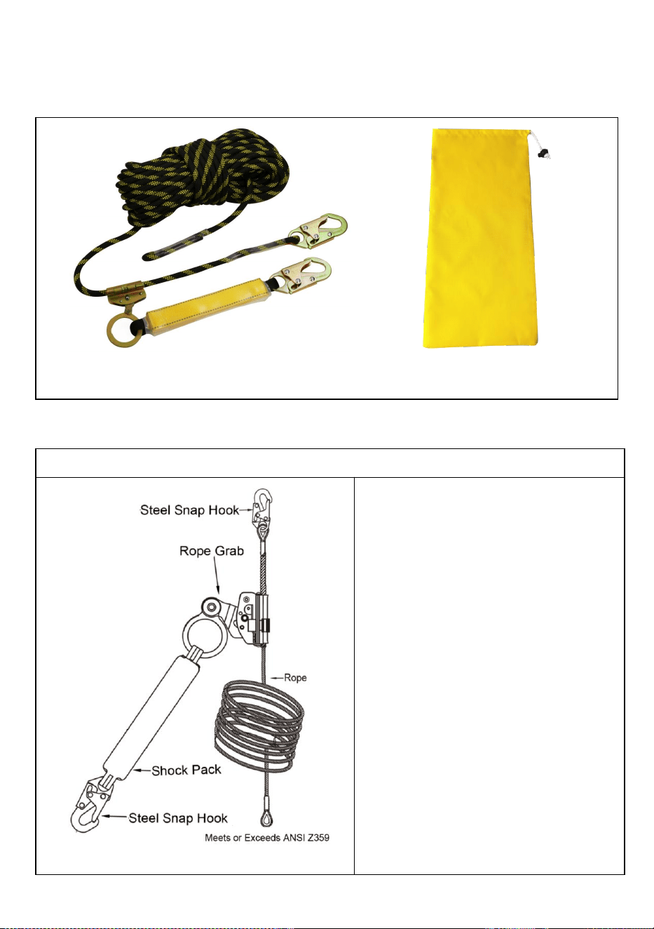
VERPAKKINGSINHOUD
Productinstructie
Valbescherming Levenslijnenconstructie
Deze reddingslijn is gemaakt van
zeer sterk polyester gevlochten
touw. De diameter van het touw is 14
mm. Het is voorzien van een
karabijnhaak die aan één uiteinde is
gesplitst en aan het andere uiteinde
een stopknoop.
Valbeveiliger met vanglijn.
Verbonden met een Shock Pack en
voorzien van een karabijnhaak aan
het uiteinde. bevestiging aan het
harnas. De valbeveiliger wordt
gebruikt over de levenslijn met
gedraaid touw.
×1
storage bag×1

Installatie en gebruik van valbeveiliging
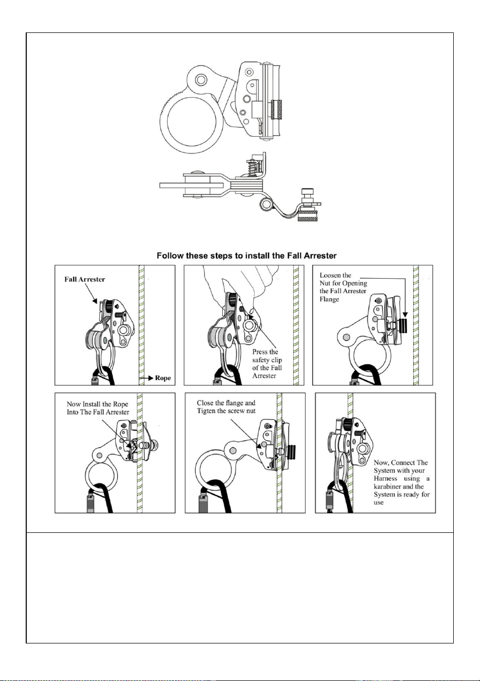
49) Elimineer alle risico's van ondergrens en beëindiging. Zorg ervoor dat de Fall
Arrester voorkomt dat de gebruiker het volgende lagere niveau bereikt en dat er
altijd voldoende valvrijheid is, of dat de Fall Arrester de voorrand van enig
valgevaar niet bereikt wanneer deze over de volledige lengte wordt gebruikt. Leg
NOOIT een knoop in een reddingslijn, behalve aan de uiterste onderkant van de
reddingslijn, om te voorkomen dat de valstop losraakt.
50) Elimineer of minimaliseer alle risico's van schommelvallen.
51) Bevestig de karabijnhaak met geïntegreerd Shock Pack aan een compatibele
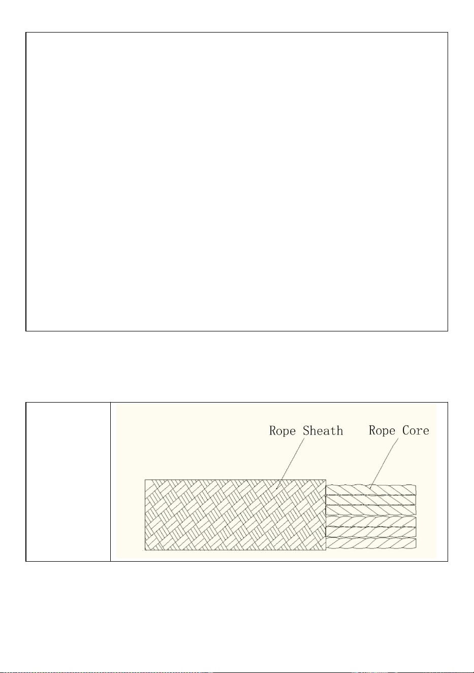
verankeringsconnector.
52) Bevestig de karabijnhaak met geïntegreerde valbeveiliging aan de
toepasselijke D-ring van het harnas.
53) Om langs de reddingslijn te bewegen, drukt u de valstophendel in en houdt u
deze vast. Pas ALTIJD de valstop aan om de speling in het systeem zoveel
mogelijk te verminderen. Wanneer deze aan een valbeveiliging is bevestigd en
over het werkoppervlak wordt verplaatst, doe dit ALTIJD door de valbeveiliging
langs een touw te verplaatsen, en NOOIT door alleen het touw zelf te bewegen.
Als u bijvoorbeeld van een dakrand naar de daktop gaat, schakelt u de hendel van
de valbeveiliger in en beweegt u deze omhoog langs de valbeveiliger terwijl u naar
de top loopt. Beweeg NIET naar de dakpiek door de valbeveiliger te verplaatsen
en houd de valbeveiliger stil; Als u dit wel doet, kan er een vrije val ontstaan die
groter is dan de niveaus die door het systeem zijn toegestaan.
54) Om de beweging van de valstop langs de reddingslijn te beperken, laat u de
valstophendel los.
55) Fall Arrester wordt geleverd met een antipaniekfunctie die automatisch in
werking treedt als de gebruiker de valbeveiliger vasthoudt en deze te stevig
vastpakt. Er moet echter op worden gelet dat u bij een val nooit een valbeveiliger
grijpt.
56) Werk NOOIT boven de valbeveiliger, tenzij de vrije val beperkt is tot 6 of
minder. Eén aansluiting per valbeveiliger. Probeer NOOIT onderdelen van de Fall
Arrester te verwijderen .
PERIODIEKE CONTROLE VAN PERSOONLIJKE
BESCHERMINGSUITRUSTING
Beschrijving
PERIODIEKE CONTROLE VAN PERSOONLIJKE BESCHERMINGSMIDDELEN ALGEMENE
OPMERKINGEN
Het uitvoeren van regelmatige periodieke controles (met vooraf door de fabrikant
bepaalde tussenpozen) is van cruciaal belang om de efficiëntie en duurzaamheid

van de apparatuur en de veiligheid van de gebruiker te garanderen. Het uitvoeren
van regelmatige periodieke inspecties is vereist door de ASTM F887-16-norm en
is daarom alleen verplicht voor bepaalde apparaatcategorieën, waarvan de
gebruiksinstructies deze verplichting uitdrukkelijk vermelden. Het uitvoeren van
periodieke controles ontheft de gebruiker niet van de verplichting om de controles
voor en na elk gebruik uit te voeren, noch om een buitengewone periodieke
controle te eisen, in het geval er zich een bijzondere gebeurtenis voordoet
(bijvoorbeeld een val, zelfs van geringe hoogte, een verandering van gebruiker
etc.), of bij twijfel over de juiste werking van het apparaat. Aandacht! Vóór het
eerste gebruik moet de eigenaar/gebruiker van PBM het
"apparaatidentificatieblad" invullen, indien aanwezig in de gebruiksaanwijzing
ervan. Let op! De Inspecteur is, na het uitvoeren van de periodieke keuring,
verantwoordelijk voor het goed functioneren van een PBM. De controle moet met
de hoogste nauwkeurigheid, zonder haast en na het voltooien van alle
noodzakelijke stappen worden uitgevoerd.
Regelmatige periodieke controles moeten worden uitgevoerd: als het vorige
gebruik van het apparaat onbekend is; minstens elke 12 maanden, bij
normaal/standaardgebruik; bij aanwezigheid van afwijkingen die tijdens de
inspecties voor en na elk gebruik worden vastgesteld; uitzonderingen daargelaten,
bij wisseling van gebruiker; het invullen van het periodieke keuringsformulier;
Aandacht! Het periodieke keuringsblad bestaat ook in de geoptimaliseerde versie
voor kits of PBM-systemen. Aandacht! Op voorwaarde dat de minimale verplichte
frequentie voor de periodieke inspectie 12 maanden bedraagt, kan deze worden
verhoogd (dwz 3 maanden, 6 maanden enz.) volgens de geldende nationale
regelgeving of de frequentie, intensiteit en wijze van gebruik (dwz zwaar gebruik,
gebruik in een mariene omgeving, corrosieve atmosferen enz.).
Het periodieke inspectieblad moet worden ingevuld: volgens de specifieke
procedure voor elk type apparaat. Climbing technology.com); het raadplegen van
het beschikbare fotomateriaal, indien aanwezig; het raadplegen van de
gebruiksaanwijzing van het apparaat; het onderzoeken van het apparaat in een
geschikte, opgeruimde en goed verlichte omgeving. Het fotomateriaal aan het
einde van de procedures gaat vergezeld van een onderschrift met uitleg en van de
volgende symbolen:
Het apparaat verkeert in goede staat of heeft slechts kleine
beschadigingen: het is dus geschikt voor gebruik.
Het apparaat heeft gemiddelde/grote schade die de primaire
functies aantast en moet daarom worden weggegooid.

Het apparaat vertoont gebreken die door smering of reiniging
kunnen worden opgelost. Als dergelijke defecten niet worden
opgelost, moet het apparaat worden weggegooid.
Het apparaat vertoont gebreken.
APPARAAT PERIODIEKE CONTROLEBLAD
1) Bekende productgeschiedenis
1.1
Controleer het bestaan en de leesbaarheid van de markeringsdetails.
1.2
Controleer of het apparaat de opslag- en/of gebruiksduur, zoals vermeld
in de specifieke gebruiksaanwijzing, niet heeft overschreden.
1.3
Controleer of het apparaat intact is en er geen onderdelen ontbreken
(vergelijk dit met een nieuw product).
1.4
Controleer of het apparaat niet buiten de fabriek is aangepast of in een
niet-erkend centrum is onderhouden (vergelijk dit met een nieuw
product).
1.5
Alle PBM’s die onverwachte degradatie vertonen, moeten in quarantaine
worden geplaatst, in afwachting van een gedetailleerde inspectie. De
gebruiker moet:
- Geef nauwkeurige informatie over de gebruiksomstandigheden.
- Meld elke uitzonderlijke gebeurtenis met betrekking tot zijn PBM.
(Voorbeelden: val- of valbeveiliging, gebruik of opslag bij extreme
temperaturen, aanpassingen buiten de faciliteiten van de fabrikant...).
2) Controle van de staat van de schede
2.1
Controleer de staat van de mantel over de volledige lengte van het touw.
Zorg ervoor dat er geen snijwonden, brandwonden, gerafelde lokken,
pluizige plekken of tekenen van chemicaliën zijn...
3) Controle van de toestand van de kern
3.1
Voer een tactiele inspectie van de kern uit over de volledige lengte van
het touw, zoals aangegeven in de tekening. Hierdoor kunt u gebieden
detecteren waar de kern beschadigd is (harde plekken, zwelling, zachte
of gekneusde gebieden...).
4) Controle van de toestand van de kern
4.1
Om de lengte van uw touw te controleren, volgt u de onderstaande
stappen:1. Rol het touw volledig uit.2. Controleer de middelste
markering van het touw. Er is een eenvoudige manier om het midden
van het touw te vinden: houd de twee uiteinden van het touw bij elkaar
en schuif vervolgens de twee strengen tegelijkertijd door je handen
totdat het midden van het touw is bereikt. Als uw touw een

middenmarkering heeft, controleer deze dan op nauwkeurigheid. Als de
markering in orde is, gaat u naar de volgende stap. Als de markering niet
op de juiste plaats zit of als er geen middelste markering is, plaats dan
een stukje plakband op het midden van het touw om de lengte te meten.
APPARAAT PERIODIEKE CONTROLEBLAD
Nee
.
Datu
m
Reden
voor
controle
Naam en
handtekening
van de persoon
die
verantwoordelij
k is voor de
controle.
Opmerkinge
n (gevonden
defecten,
uitgevoerde
reparaties of
andere
relevante
informatie)
Controlee
r de
resultaten
Datum
van de
volgend
e
controle
1
□
Periodie
k
□ Extra
□
Apparaat
geschikt
voor
gebruik.
□
Apparaat
ongeschik
t voor
gebruik
2
□
Periodie
k
□ Extra
□
Apparaat
geschikt
voor
gebruik.
□
Apparaat
ongeschik
t voor
gebruik
3
□
Periodie
k
□ Extra
□
Apparaat
geschikt
voor
gebruik.
□
Apparaat
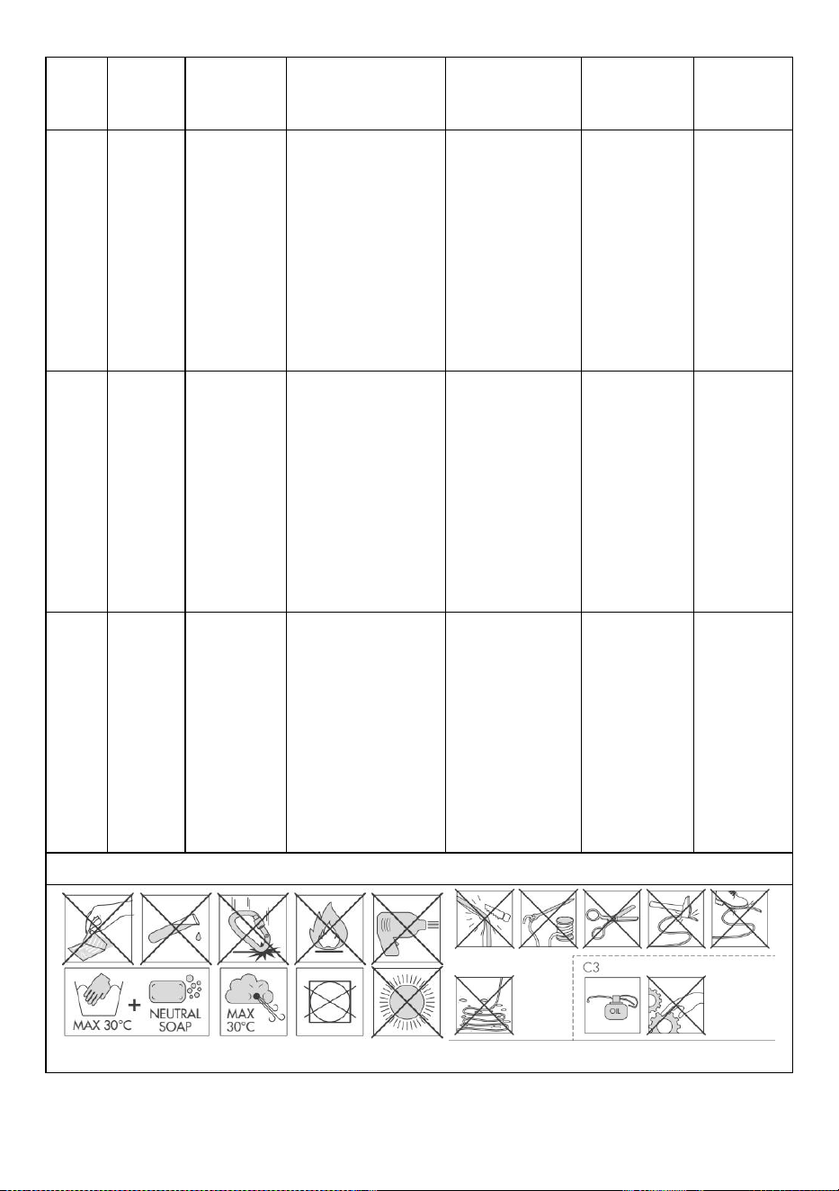
ongeschik
t voor
gebruik
4
□
Periodie
k
□ Extra
□
Apparaat
geschikt
voor
gebruik.
□
Apparaat
ongeschik
t voor
gebruik
5
□
Periodie
k
□ Extra
□
Apparaat
geschikt
voor
gebruik.
□
Apparaat
ongeschik
t voor
gebruik
6
□
Periodie
k
□ Extra
□
Apparaat
geschikt
voor
gebruik.
□
Apparaat
ongeschik
t voor
gebruik
WAARSCHUWINGEN
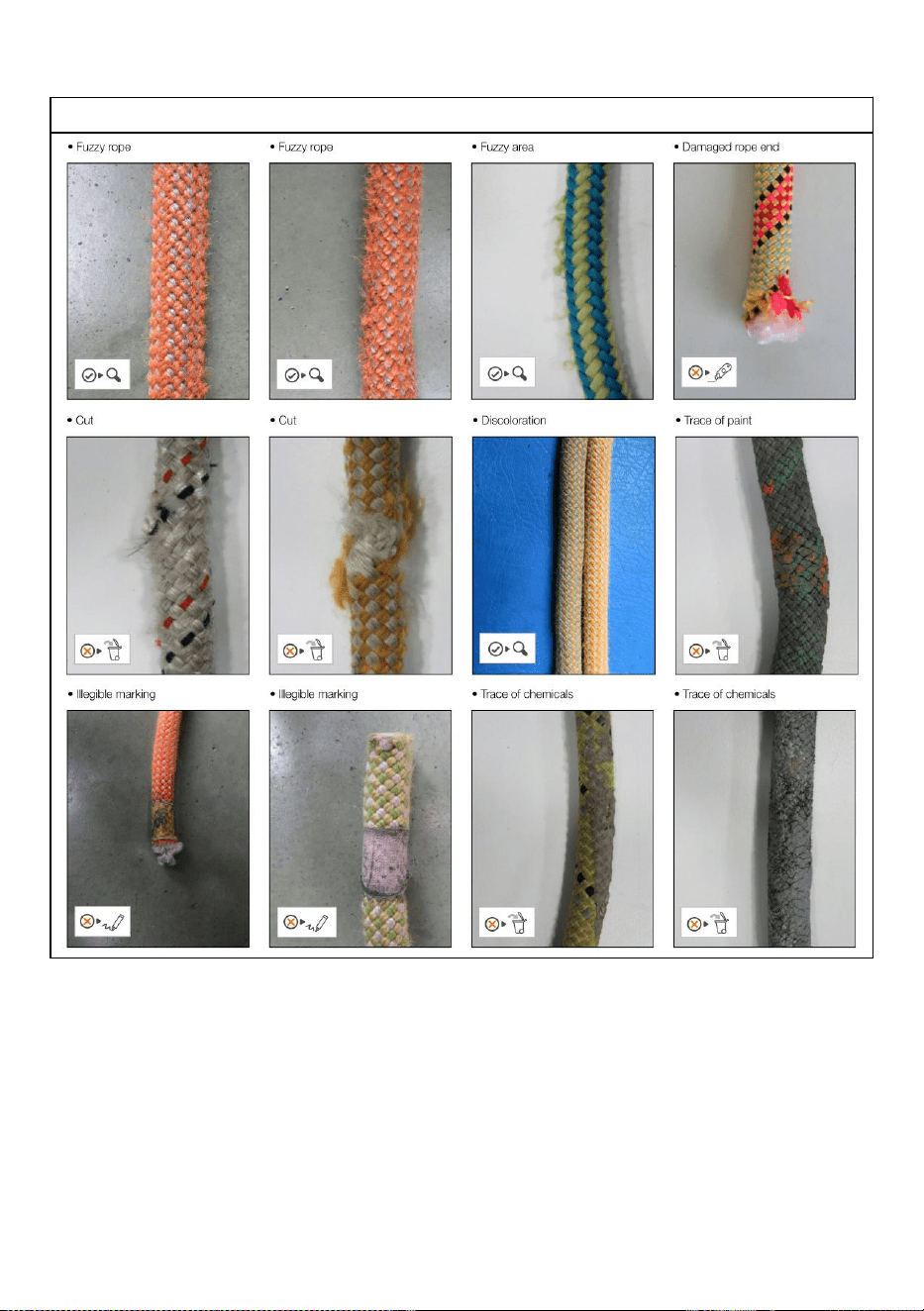
FOTO BIJLAGE

VOLTOOIING
Adres : Shuangchenglu 803nong11hao1602A-1609shi, baoshanqu,
shanghai 200000 CN.
Geïmporteerd naar AUS: SIHAO PTY LTD, 1 ROKEVA
STREETEASTWOOD NSW 2122 Australië
Geïmporteerd naar de VS: Sanven Technology Ltd., Suite 250, 9166
Anaheim Place, Rancho Cucamonga, CA 91730
REP
EC
E-CrossStu GmbH
Mainzer Landstr.69, 60329 Frankfurt am Main.
REP
UK
YH CONSULTING LIMITED.
C/O YH Consulting Limited Office 147, Centurion House,
London Road, Staines-upon-Thames, Surrey, TW18 4AX


Teknisk Support och e-garanticertifikat
www.vevor.com/support
FALLSKYDD LIVLINOR
ANVÄNDARMANUAL
MODELLNR: ROPE-S-25, ROPE-S-50,
ROPE-S-100, ROPE-Z-14-150
We continue to be committed to provide you tools with competitive price.
"Save Half", "Half Price" or any other similar expressions used by us only represents an
estimate of savings you might benefit from buying certain tools with us compared to the major
top brands and does not necessarily mean to cover all categories of tools offered by us. You
are kindly reminded to verify carefully when you are placing an order with us if you are
actually saving half in comparison with the top major brands.

MODELLNR: ROPE-S-25 , ROPE-S-50 , ROPE-S-100 , ROPE-Z-14-150
Have product questions? Need technical support? Please feel free to
contact us:
Technical Support and E-Warranty Certificate
www.vevor.com/support
NEED HELP? CONTACT US!
This is the original instruction, please read all manual instructions
carefully before operating. VEVOR reserves a clear interpretation of our
user manual. The appearance of the product shall be subject to the
product you received. Please forgive us that we won't inform you again if
there are any technology or software updates on our product.
Fall Protection Lifelines

VARNING:
Läs denna bruksanvisning noggrant innan du använder produkten.
Underlåtenhet att göra det kan leda till allvarliga skador. SPARA
DENNA MANUAL
ALLMÄN INFORMATION
Fallskydd livlinor
Varumärke
Referensstandarder
ANSI/ASSE Z 359
"VEVOR. Fall Protection Lifelines " är en justerbar fasthållningsanordning som
överensstämmer med standarden ANSI/ASSE Z359.
Denna manual måste läsas och förstås i sin helhet. Dessa instruktioner är
avsedda att uppfylla tillverkarens instruktioner. Användaren måste till fullo förstå
den korrekta utrustningens användning och begränsningar.
TEKNISKA SPECIFIKATIONER
Modell
ROPE-S-25
ROPE-S-50
ROPE-S-100
ROPE-Z-14-150
huvudmateria
l
Dacron
Färg
Svart gul
Nettovikt (kg)
2.06
3
4.7
7.6
linjeövervaka
re (ft)
25
50
100
150

PAKET INNEHÅLL
Produktinstruktion
Fall Protection Lifelines konstruktion
Denna livlina består av flätat rep av
höghållfast polyester. Diametern på
repet är 14 mm. Den är försedd med
en karbinhake skarvad i ena änden
och den andra änden har en
stoppknut.
Fallskydd med snöre Ansluten med
ett chockpaket och har en Snap
Hook i slutet. fäste på selen.
Fallskyddet används över den
tvinnade repets livlina.
×1
storage bag×1
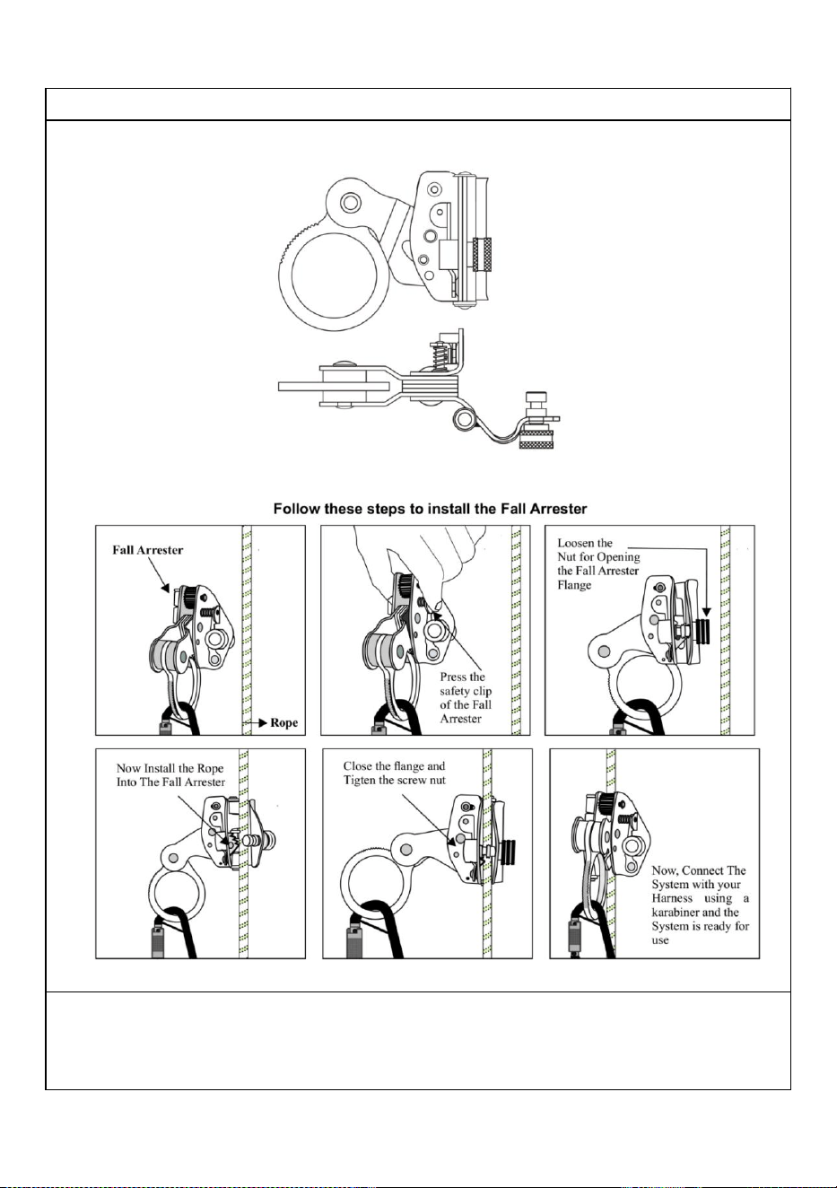
Installation och användning av fallskydd
57) Eliminera all risk för lägre ände och uppsägning. Antingen se till att fallskyddet
hindrar användaren från att slå nästa lägre nivå och att det alltid finns tillräckligt
med fallfrigång, eller att fallskyddet inte når framkanten av någon fallrisk när den
används i sin fulla längd. Knyt ALDRIG en knut i en livlina, förutom längst ner på
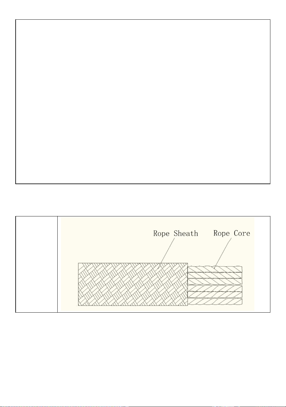
livlinan för att förhindra att fallskyddet lossnar.
58) Eliminera eller minimera alla risker för svängfall.
59) Fäst karbinkrok med integrerat Shock Pack på en kompatibel
förankringskontakt.
60) Fäst karbinhaken med integrerat fallskydd på lämplig sele D-ring.
61) För att förflytta dig längs livlinan, komprimera och håll fallskyddshandtaget.
Justera ALLTID Fallskydd för att minska slack i systemet så mycket som möjligt.
När den är fäst vid ett fallskydd och rör sig längs arbetsytan, gör det ALLTID
genom att flytta fallskyddet längs repet, och ALDRIG genom att bara flytta själva
repet. Till exempel, om du flyttar från en takkant till taktoppen, aktivera handtaget
på fallskyddet och flyttar det uppför fallskyddet medan du går till toppen. Flytta
INTE upp till taktoppen genom att flytta fallskyddet och håll fallskyddet
stillastående; att göra det kan skapa fritt fall utöver de nivåer som systemet tillåter.
62) För att begränsa fallskyddets rörelse längs livlinan, släpp fallskyddshandtaget.
63) Fallskyddet kommer med en antipanikfunktion som agerar automatiskt om
användaren håller i fallskyddet och greppar den för hårt. Man måste dock se till att
aldrig ta tag i en fallskydd vid fall.
64) Arbeta ALDRIG ovanför fallskyddet om inte fritt fall är begränsat till 6 eller
mindre. En anslutning per fallskydd. Försök ALDRIG att ta bort komponenter från
fallskyddet .
PERIODISK KONTROLL AV PERSONLIG SKYDDSUTRUSTNING
D
beskrivning
PERIODISK KONTROLL AV PERSONLIG SKYDDSUTRUSTNING ALLMÄNNA ANMÄRKNINGAR
Att utföra regelbundna periodiska kontroller (med intervaller som bestäms av
tillverkaren) är avgörande för att säkerställa utrustningens effektivitet och
hållbarhet samt användarens säkerhet. Genomförandet av regelbundna
periodiska inspektioner krävs enligt ASTM F887-16-standarden och det är därför
obligatoriskt endast för vissa enhetskategorier, vars bruksanvisningar uttryckligen
anger en sådan skyldighet. Att utföra periodiska kontroller befriar inte användaren
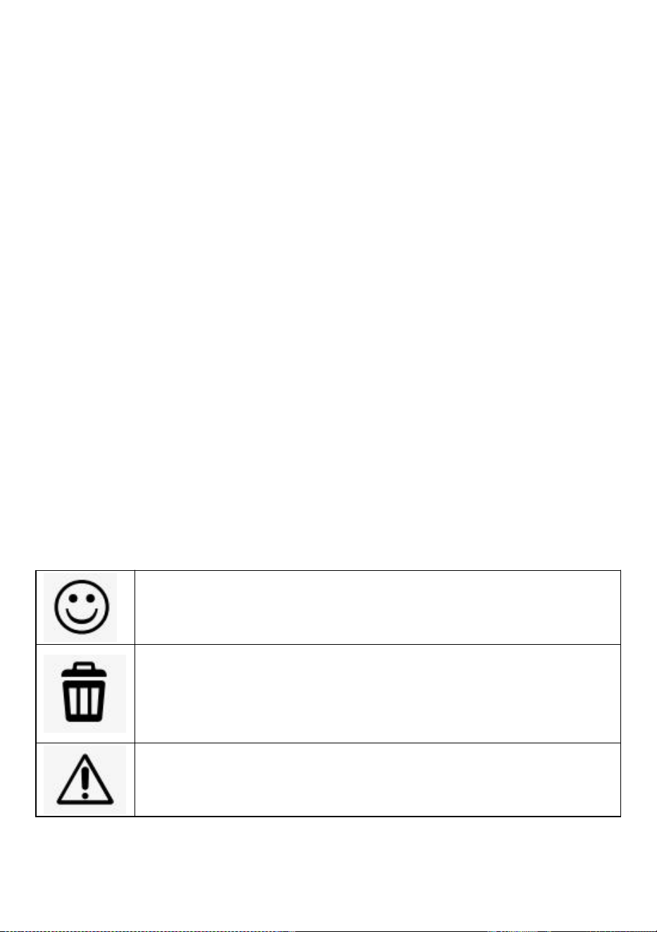
från skyldigheten att utföra kontrollerna före och efter varje användning, och inte
heller att kräva en extraordinär periodisk kontroll, om en enastående händelse
inträffar (t.ex. ett fall, även från låg höjd, en byte av användare etc.), eller vid tvivel
om enhetens korrekta funktion. Uppmärksamhet! Innan första användningen
måste ägaren/användaren av PPE fylla i "enhetsidentifikationsbladet" när det finns
i användarens instruktioner för densamma, OBS! Inspektören är, efter att ha utfört
den periodiska inspektionen, ansvarig för att en personlig skyddsutrustning
fungerar korrekt. Kontrollen måste utföras med högsta noggrannhet, utan brådska
och efter att ha genomfört alla nödvändiga steg.
Regelbundna periodiska kontroller måste utföras: om den tidigare användningen
av enheten är okänd;minst var 12:e månad, med normal/standard användning;i
närvaro av avvikelser som upptäckts under inspektionerna före och efter varje
användning; med undantag för undantag, närhelst det sker ett byte av
användare;fylla i bladet för periodisk inspektion,; Uppmärksamhet! Det periodiska
inspektionsbladet finns också i den optimerade versionen för kit eller system av
PPE. Uppmärksamhet! Förutsatt att den minsta obligatoriska frekvensen för den
periodiska inspektionen är 12 månader, kan den ökas (dvs. 3 månader, 6 månader
etc.) enligt gällande nationella bestämmelser eller frekvens, intensitet och
användningssätt (dvs. tung användning, användning i en marin miljö, korrosiva
atmosfärer etc.).
Den periodiska inspektionen måste fyllas i: enligt den specifika proceduren för
varje typ av anordning. climbing technology.com); konsultation av tillgängligt
fotografiskt material, där sådant finns; konsultation av bruksanvisningen för
enheten; undersökning av enheten i en lämplig, städad och väl upplyst miljö. Det
fotografiska materialet i slutet av procedurerna åtföljs av en förklaringstext och av
följande symboler:
Enheten är i gott skick eller har endast mindre skador: den är därför
lämplig för användning.
Enheten har medelstora/stora skador som påverkar dess primära
funktioner och måste därför kasseras.
Enheten har defekter som kan lösas genom smörjning eller
rengöring. Om sådana defekter inte åtgärdas måste enheten
kasseras.
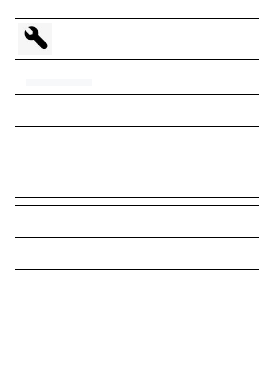
Enheten har defekter.
ENHETS PERIODISKA KONTROLLARK
1) Känd produkthistorik
1.1
Kontrollera märkningsdetaljernas existens och läsbarhet.
1.2
Kontrollera att enheten inte har överskridit livslängden för lagring
och/eller användning, som anges i den specifika bruksanvisningen.
1.3
Kontrollera att enheten är intakt och att inga delar saknas (kontrollera
mot en ny produkt).
1.4
Kontrollera att enheten inte har modifierats utanför fabriken eller servas i
ett icke-godkänt center (kontrollera mot en ny produkt).
1.5
All personlig skyddsutrustning som visar oväntad nedbrytning bör sättas
i karantän i väntan på en detaljerad inspektion. Användaren bör:
- Ge exakt information om användningsförhållandena.
- Rapportera alla exceptionella händelser angående hans personliga
skyddsutrustning. (Exempel: fall- eller fallstopp, användning eller
förvaring vid extrema temperaturer, modifiering utanför tillverkarens
anläggningar...).
2) Kontroll av skidans skick
2.1
Kontrollera mantelns skick över hela repets längd. Se till att det inte
finns skärsår, brännskador, slitna trådar, luddiga områden eller tecken
på kemikalier...
3) Kontrollera kärnans tillstånd
3.1
Gör en taktil inspektion av kärnan över repets fulla längd, enligt
ritningen. Detta gör att du kan upptäcka områden där kärnan är skadad
(hårda fläckar, svullnad, mjuka eller krossade områden...).
4) Kontrollera kärnans tillstånd
4.1
För att kontrollera längden på ditt rep, följ stegen nedan:1. Rulla upp
repet helt.2. Kontrollera mittmärket på repet. Det finns ett enkelt sätt att
hitta mitten av repet: håll ihop de två repändarna och skjut sedan de två
trådarna samtidigt genom dina händer tills mitten av repet nås. Om ditt
rep har ett mellanmärke, kontrollera det för noggrannhet. Om
markeringen är OK, gå till nästa steg. Om märket inte är på rätt plats
eller om det inte finns något mittmärke, placera en bit tejp vid repets
mittpunkt för att hjälpa till att mäta dess längd.

ENHETS PERIODISKA KONTROLLARK
Nej
.
Datu
m
Anlednin
g till
kontroll
Namn och
underskrift på
den
kontrollansvarig
e.
Anmärkning
ar (hittade
defekter,
utförda
reparationer
eller annan
relevant
information)
Kontrollera
resultaten
Datum
för
nästa
kontro
ll
1
□
Periodisk
□
Ytterligar
e
□ Enheten
passar för
användnin
g.
□ Enheten
är olämplig
för
användnin
g
2
□
Periodisk
□
Ytterligar
e
□ Enheten
passar för
användnin
g.
□ Enheten
är olämplig
för
användnin
g
3
□
Periodisk
□
Ytterligar
e
□ Enheten
passar för
användnin
g.
□ Enheten
är olämplig
för
användnin
g
4
□
Periodisk
□
Ytterligar
e
□ Enheten
passar för
användnin
g.
□ Enheten
är olämplig
för
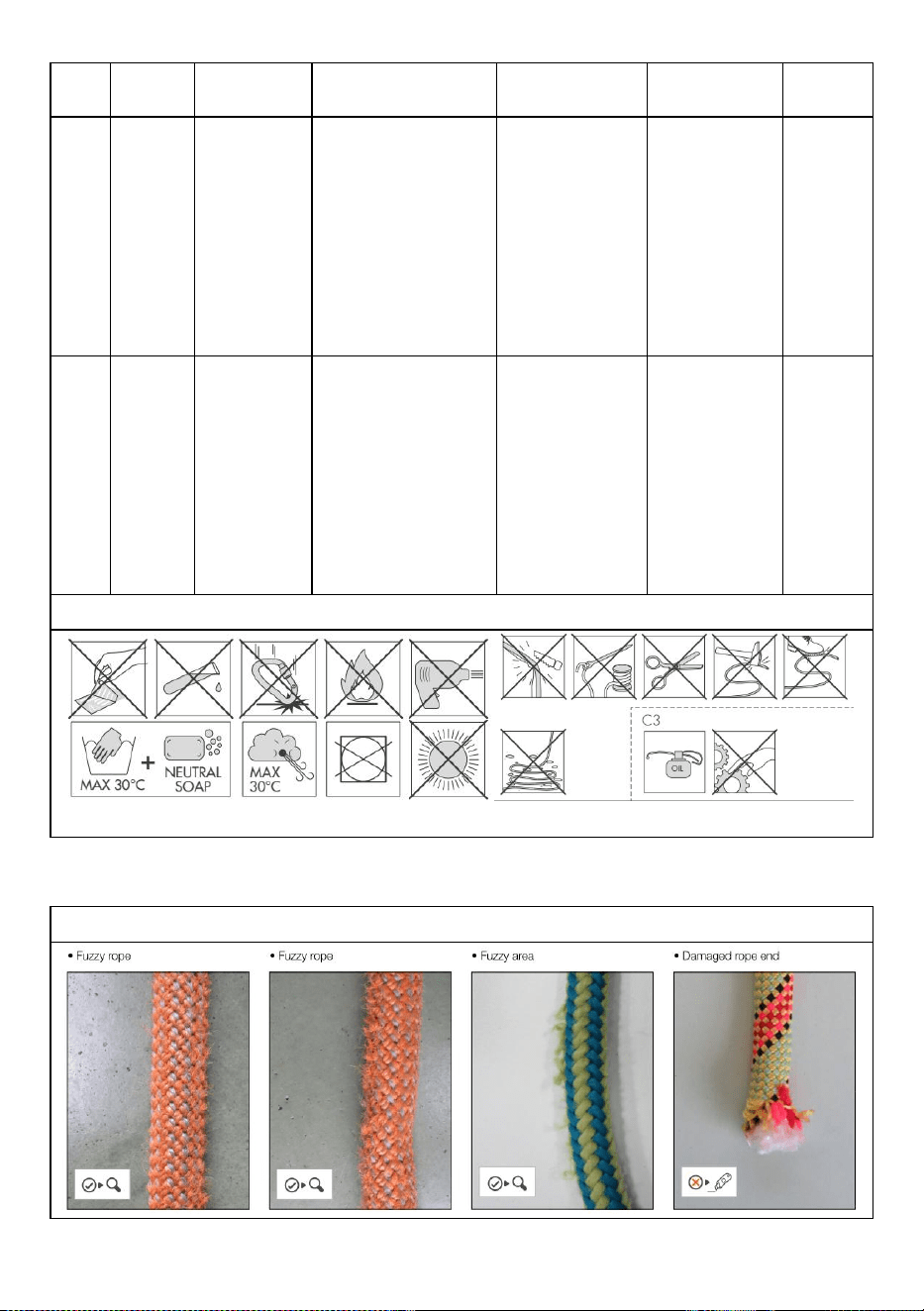
användnin
g
5
□
Periodisk
□
Ytterligar
e
□ Enheten
passar för
användnin
g.
□ Enheten
är olämplig
för
användnin
g
6
□
Periodisk
□
Ytterligar
e
□ Enheten
passar för
användnin
g.
□ Enheten
är olämplig
för
användnin
g
VARNINGAR
FOTOBILAGA

KOMPLETTERING

Adress : Shuangchenglu 803nong11hao1602A-1609shi, baoshanqu,
shanghai 200000 CN.
Importerad till AUS: SIHAO PTY LTD, 1 ROKEVA STREETEASTWOOD
NSW 2122 Australien
Importerad till USA: Sanven Technology Ltd., Suite 250, 9166 Anaheim
Place, Rancho Cucamonga, CA 91730
REP
EC
E-CrossStu GmbH
Mainzer Landstr.69, 60329 Frankfurt am Main.
REP
UK
YH CONSULTING LIMITED.
C/O YH Consulting Limited Office 147, Centurion House,
London Road, Staines-upon-Thames, Surrey, TW18 4AX