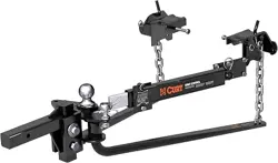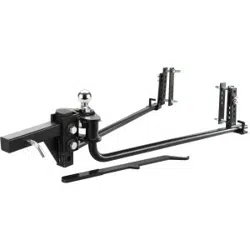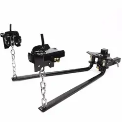
HITCH WEIGHT DISTRIBUTION 1000LBS
SAVE THIS MANUAL: KEEP THIS MANUAL FOR SAFETY WARNINGS, PRECAUTIONS, ASSEMBLY,
OPERATING, INSPECTION, MAINTENANCE AND CLEANING PROCEDURES. WRITE THE
PRODUCT’S SERIAL NUMBER ON THE BACK OF THE MANUAL NEAR THE ASSEMBLY DIAGRAM
(OR MONTH AND YEAR OF PURCHASE IF PRODUCT HAS NO NUMBER).
OWNER’S MANUAL AND SAFETY INSTRUCTIONS
ITEM: 22005
FOR QUESTIONS PLEASE CALL OUR CUSTOMER SUPPORT: (909) 628 0880 MON-FRI 9AM TO 3PM PST
1
IMPORTANT SAFETY INFORMATION
The warnings, precautions, and instructions discussed in this instruction manual cannot cover all possible
conditions and situations that may occur. It must be understood by the operator that common sense and
caution are factors which cannot be built into this product, but must be supplied by the operator. Read
carefully and understand all ASSEMBLY AND OPERATION INSTRUCTIONS before operating. Failure to
follow the safety rules and other basic safety precautions may result in serious personal injury.
Loaded ball height should never be greater than the uncoupled ball height. Front wheel overload and
loss of rear wheel traction can result and can lead to unstable handling. It can reduce braking ability and
create a tendency to "jackknife when turning or braking at the same time.
If the loaded ball height is greater than the uncoupled height, reduce take up on the spring bar chains and
remeasure and adjust until the proper height is obtained.
CAUTION: If the lift chain is angled fore or aft at the top within the lift bracket, it may catch on the bracket
when turning. This could damage the lift bracket or pry it open.
FRONT WHEEL DRIVE VEHICLES:
Do not attempt to hook-up or tow with the rear tires of the towing vehicle removed. Severe structural
damage to the towing vehi cle, hitch and trailer may result. A towing vehicle/trailer combination cannot be
controlled adequately unless the towing vehicles rear wheels are carrying their share of the load.
CHECK ALL TRAILER TO TOWING VEHICLE CONNECTIONS FOR SECURITY AND OPERATION
Surge brakes usually require a small amount of fore and aft movement for their actuating mechanism
to functioo. To avoid restricting movement, it may be necessary to increase the number of chain links
between the lift brackets and spring bars, by tilt ing the head down. Tighten the two 3/4’ bolts to 260 ft.
lbs. torque once head angle is set. Those surge brake actuators not designed for use with a weight
distributing hitch, may bind and not operate freely. Check your surge brake operating instructions for any
specic requirements regarding their use with weight distributing hitches.
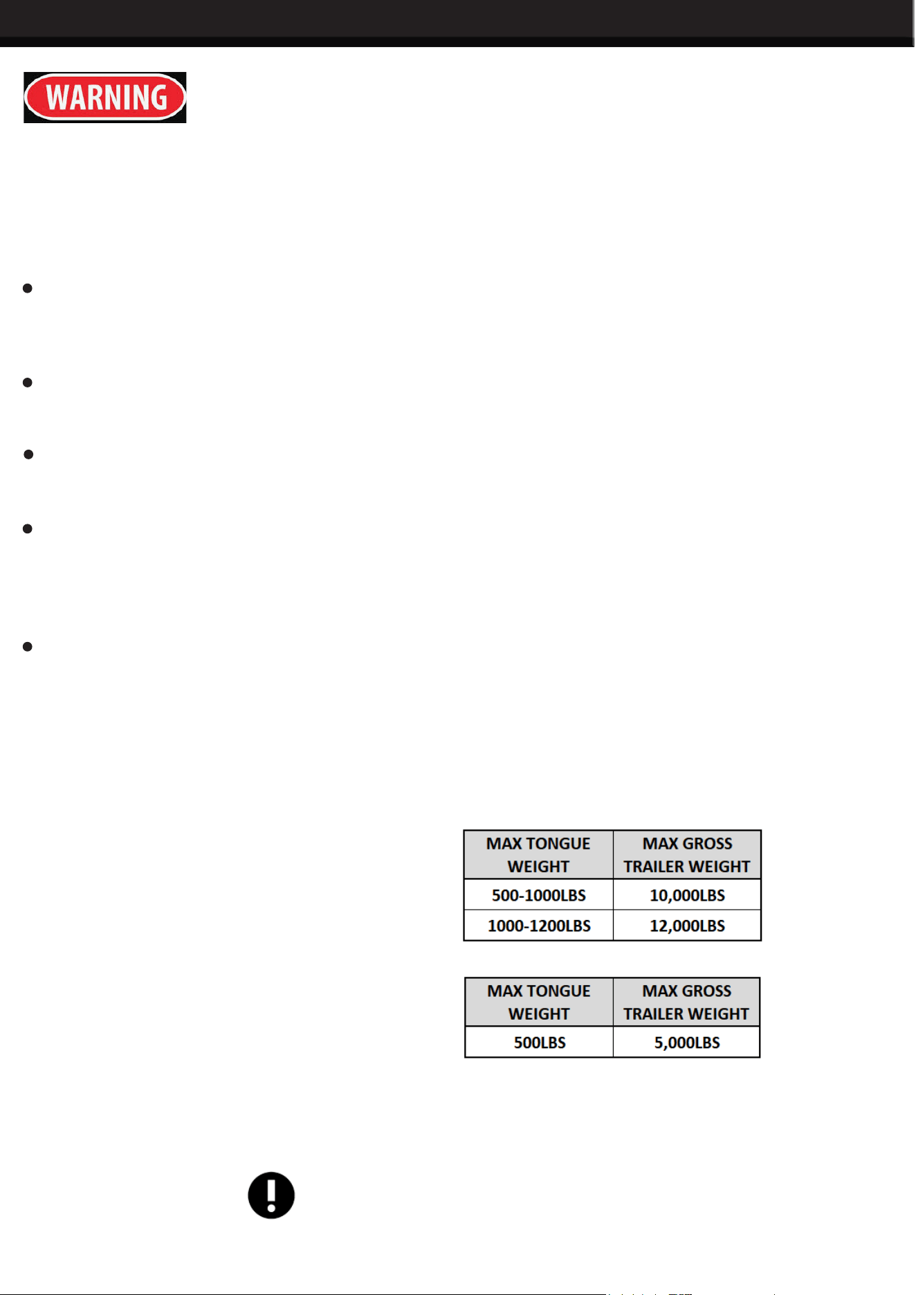
Rating when used as a weight distributing
hitch with spring bars:
Rating when used as a weight carrying
hitch without spring bars: Do not exceed the
towing vehicle manufacturer’s load rating.
CAUTION: The tongue weight rating of the spring bars represents the capacity
of a pair of bars, NOT an
individual bar. Always use a pair of spring bars and be sure they are of the same weight rating.
SAVE THESE WARNINGS
2
OPERATION
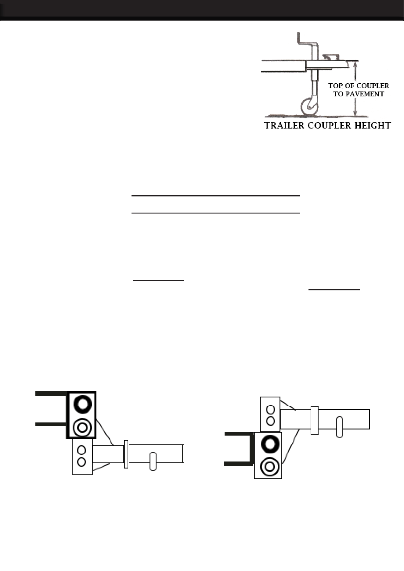
MEASURE TRAILER COUPLER HEIGHT
1. Line
up the tow vehicle and trailer on level pavement in a straight
position. Use the trailer tongue jack to level the trailer. (Built in
level on the 35001b and 45001b electric tongue jacks). Measure
the distance from pavement to the top of the coupler socket and
record here ______ , See Illustration 2.
MEASURE THE TOW VEHICLE
2. For
vehicles with air springs, air shocks or automatic leveling systems only: Check vehicle owners manual
or other instructions on these items. Unless otherwise indicated, air springs and air shocks should be deflated
to their minimum recommended pressure before assembling and adjusting the weight distributing hitch.
Pick reference points on the front and rear bumper of towing vehicle. Measure and record height to pavement.
MEASURE THE TOW VEHICLE
MEASURE THE TOW VEHICLE
DETERMINE THE “TARGET UNCOUPLED BALL HEIGHT FOR TOW VEHICLE
3. Tow vehicle uncoupled ball height will be set higher than coupler height measured in Step 1, to allow for
vehicle squat when coupled to trailer.
For trucks or other stiffly sprung vehicles; add 1/16" to the height measured in Step 1, for each 100 lbs. of
tongue weight. Record ball height. _______
For passenger cars, add 1/8” for each 100 lbs. of tongue weight Record ball height. __
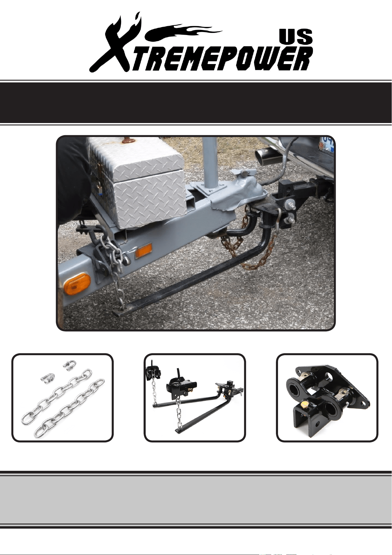
INSTALL SHANK, HITCH HEAD AND BALL
4. Insert shank #1 into receiver on towing vehicle and secure with hitch pin and hair pin.
NOTE: To obtain proper ball height on high ground clearance vehicles, shank may be inverted as shown
in Illustration 3. If shank is used in an inverted position, check for adequate ground clearance. Accessory
shanks with greater height and length are available from your dealer.
5. Select
a hitch ball to match the trailer coupler socket, having a 1" or 1-1/4" threaded shank and capacity
exceeding the gross trailer weight. When using a ball with a 1" shank, the reducer bushing must be placed
in the ball hole in the head assembly. Install ball, but do not tighten at this time.
3
OPERATION
5. Select
a hitch ball to match the trailer
coupler socket, having a 1" or 1-1/4"
threaded shank and capacity exceeding
the gross trailer weight. When using a
ball with a 1" shank, the reducer bushing
must be placed in the ball hole in the
head assembly. Install ball, but do not
tighten at this time.
7. Place four hardened washers (14) on pin (13) and insert pin into the unthreaded hole in the upper portion
of the head channel. The number of washers may have to be changed later.
8. Install head on shank at marked position. Insert the 3/4” x 4-1/2” hex bolt (6e) through the lower hole in
the head channel. Rotate the head forward as far as it will go. Ball should be vertical or tilted slightly back.
If it is not, change the number of washers on the pin and re-assemble as before. Insert the remaining 3/4” x
4-1/2” bolt (10) with toothed washer {12) through the upper slotted hole. Install a second toothed washer on
the upper bolt. Start locknuts (11) on to bolts only nger tight. Thread the 5/8 Hex Bolt #15 into the threaded
hole in lower channel of head and tighten against shank.
9. Tighten bolt (10) to 260 ft. lbs. torque.
10. Place head assembly back into hitch assembly on towing vehicle and tighten the trailer ball to torque
specied by the ball manufacturer.
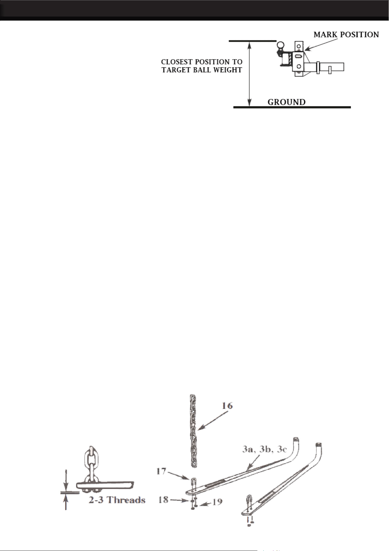
ASSEMBLE, LUBRICATE AND INSTALL SPRING BARS:
1. Assemble
the lift chains (16) to the tapered ends of each spring bar using the 3/8” u-bolts (17),
3/8" flat washers (18) and the 3/8” hex locknut's (19) as shown below in Illustration 5. Let 2 or 3 threads
of the u-bolts extend out through the bottom of each locknut. The chain must be free to move in the u-bolt.
2. Apply a heavy fibrous grease on the round end of each spring bar and push end up into
head socket until you hear a click. This will indicate that the spring bar is locked in
place.
NOTE: To release spring bar, lift up slightly on spring bar and gently pull out on the retaining pin in the hitch
head. The spring bar should drop free of hitch head.
OPERATION
4
1. Using the trailer tongue jack, lower the coupler onto the ball and close coupler latch. Do not retract jack
fully at this time.
Allow the jack to support some of the tongue weight.
2. Raise the front of the trailer and back of the tow vehicle approximately 3” with tongue jack.
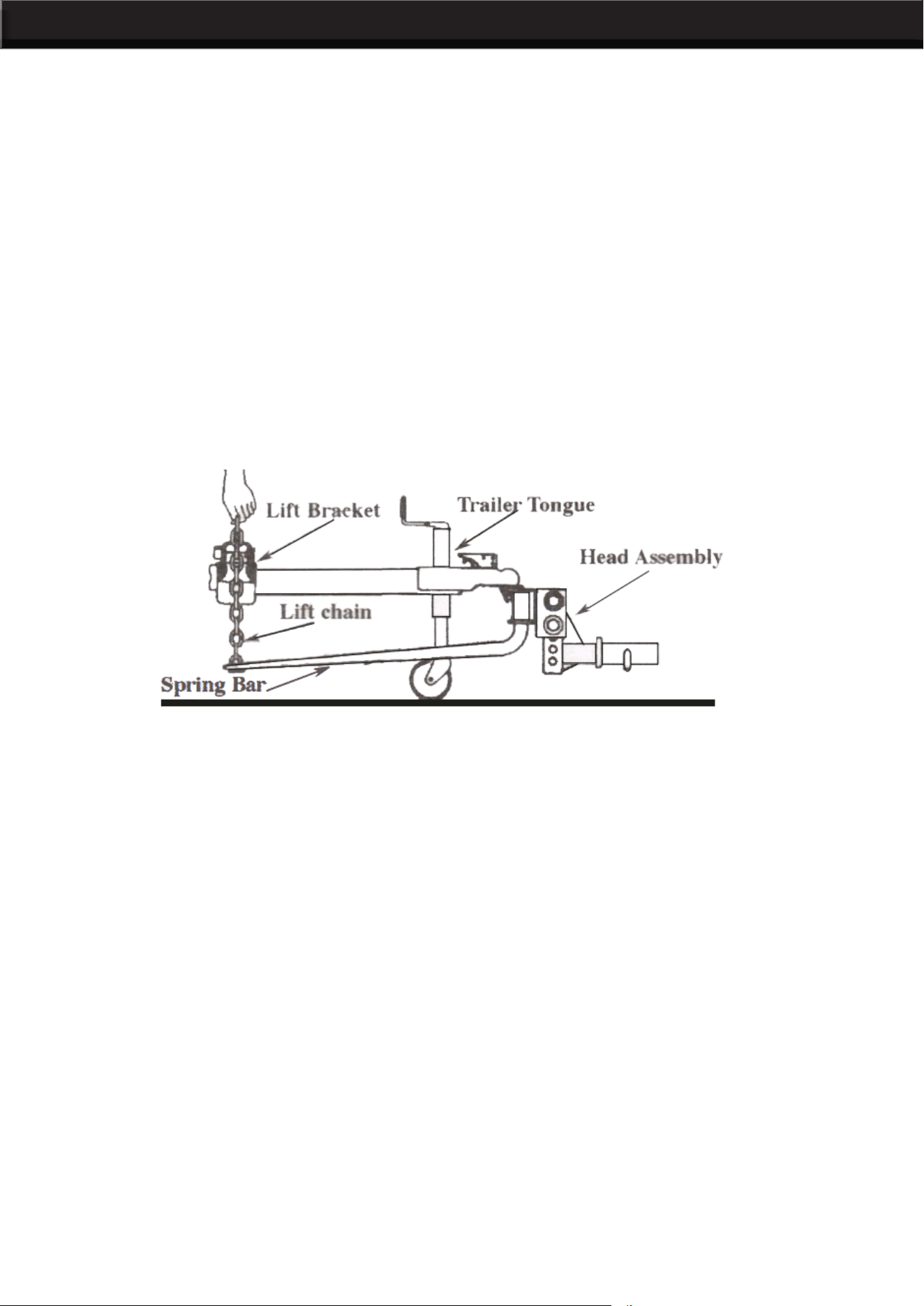
1.Position the spring bar, which has been attached to the hitch head, parallel with the trailer tongue. Hold
the lift chain vertical up alongside the trailer tongue. Position the lift bracket on the trailer tongue so that the
chain is centered between the lift bracket as shown on Illustration 6 below.
CAUTION: If chain is angled fore or aft at the top within the lift bracket, it my catch on the bracket when
turning. This could dam age the lift bracket or pry it open.
ATTACHING TRAILER TO BALL
The following directions apply to trailers with an “A” frame tongue.
INSTALLING THE CHAIN LIFT BRACKETS
2. Mark the location of the lift bracket on the trailer tongue.
3. Install the 1/2” x 3-1/2” bolt (6) into the threaded hole in the lift bracket. Turn the bolt in until it contacts the
trailer tongue, then tighten 1/4 turn with a wrench. DO NOT OVERTIGHTEN.
The amount of leveling is adjusted by engaging different spring bar chain links with the lift unit. Before
proceeding, read the “LIFT UNIT OPERATION” section on following page.
HOOKING UP SPRING BARS
1. With the lift bracket in the raised and locked position, pull straight up rmly on the spring bar lift chain.
Note which link is closest to the lift bracket hook. Mark the next lower chain link.
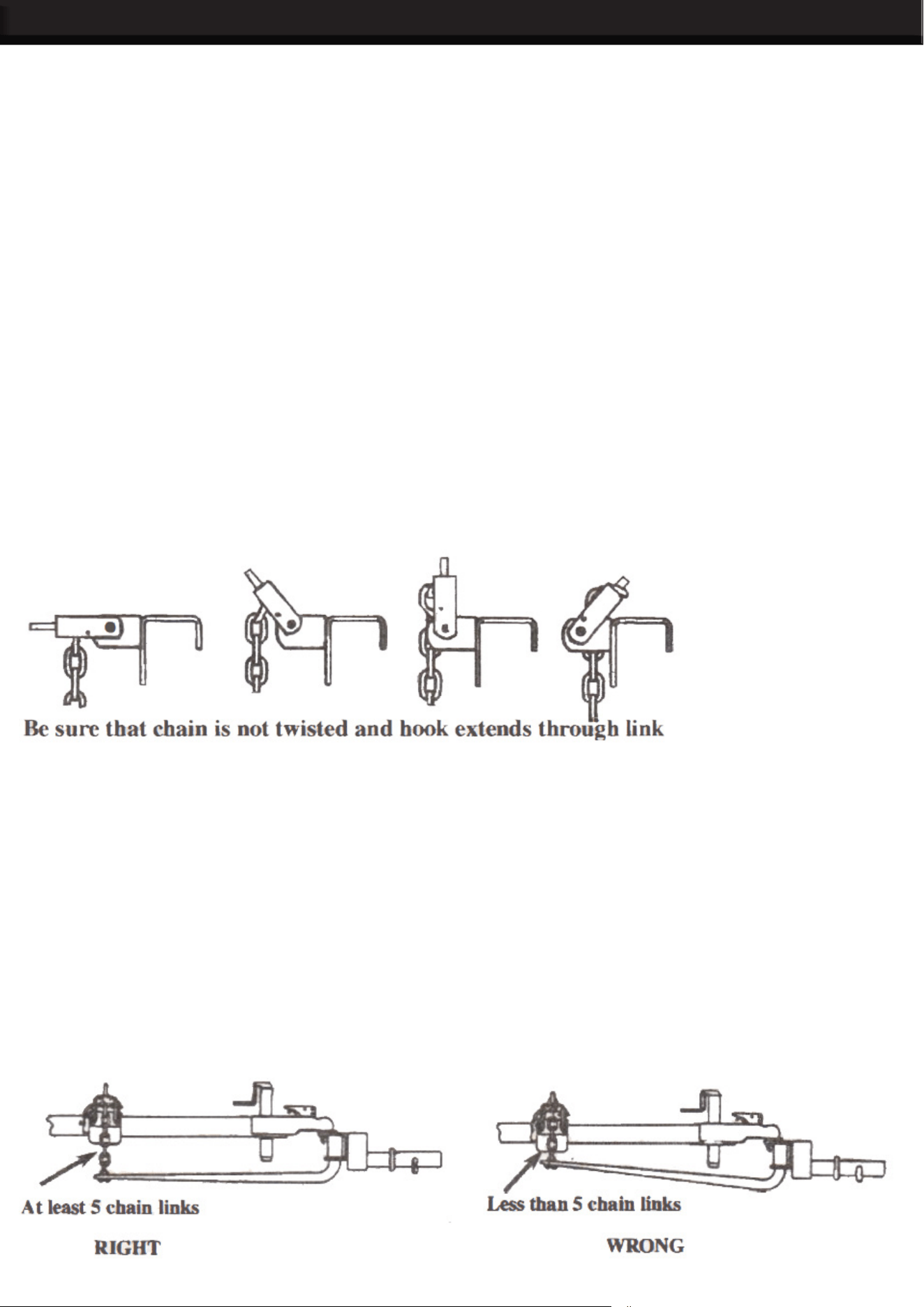
2. Lower the lift bracket and slip the marked link over the hook. Be sure that the chain is not twisted.
3. Raise the lift bracket and secure with the locking pin. Repeat procedure on opposite side of trailer using
the same number of chain links as the rst side. See Illustration 7.
4. Retract the trailer tongue jack so the hitch is now carrying the full trailer tongue weight.
OPERATION
5
Before raising or lowering the lift bracket, raise the front of the trailer to reduce the spring bar chain tension.
This will make the lift bracket operation easier and safer.
WARNING: Keep clear of the pivot path of all moving parts when there is tension on the spring bar chain.
Maintain control of the lift handle at all times when raising or lowering the spring bar. Be sure that the locking
pin is in place before leaving lift bracket in the up position.
LIFT BRACKET OPERATION
1. Remove the locking pin from lift bracket.
2. Insert lift handle onto the rod above the lift chain attachment.
3. Carefully lower bracket with handle. It will require effort to bring the bracket over center and then to resist
the chain tension as the bracket rotates downward.
TO LOWER FROM FULLY RAISED AND LOCKED POSITION
1. Slip the marked chain link over hook on lift bracket.
2. Insert lift handle onto heavier rod above lift chain attachment.
3. Using the handle, raise the lift bracket up and over center so that it is fully seated against the mounting
bracket.
TO RAISE LIFT BRACKET
1. Vehicle should settle evenly, within 1/2". Remeasure the front and rear bumper reference points. If the
front has settled much more than the rear, increase the number of chain links between the lift bracket and
the spring bar. The spring bars should be nearly horizontal when correct height is achieved.
2. When even settling and correct spring bar position have been achieved, mark the spring bar chain at the
hooked position, with paint, for future hook up reference.
NOTE: Illustration 7, shows the correct and incorrect hook-up position of the spring bars. To allow movement
when turning, there should be at least 5 links between the lift bracket and the spring bar. The number of links
should be the same on both bars. Adjust head tilt to accomplish correct chain length.
CHECK VEHICLE HEIGHT AND ADJUST SPRING BARS IF NECESSARY
OPERATION
6
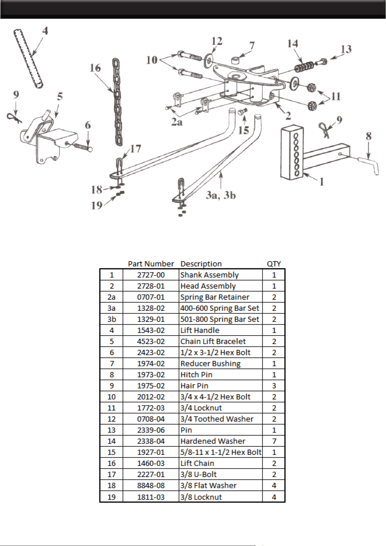
PARTS LIST

OPERATION TIPS
7
DRIVING A TOW VEHICLE
Good habits for normal driving need extra emphasis when towing a trailer. The additional weight of the
trailer affects acceleration and braking. Extra time should be allowed for passing, stopping and changing
lanes. Signal well in advance of a maneuver to let other drivers know your intentions. Sever bumps
and badly undulating roads can damage your towing vehicle, hitch and trailer, and should
be negotiated at a slow, steady speed. If any part of your towing system “bottoms out" or if you
suspect damage may have occurred in any other way, pull over and make a thorough inspection.
Correct any problems before resuming travel.
CHECK YOUR EQUIPMENT
Periodically check the condition of all your towing equipment and keep in top condition.
TRAILER LOADING
Proper trailer loading is very important. Heavy items should be placed close to the floor near the trailer
axle centerline. The load should be balanced side to side and firmly secured in the trailer to prevent
shifting. Tongue weight should be 10-15% of the gross trailer weight for most trailers. To low a tongue
weight often produces tendency to sway.
SWAY CONTROL
A sway control device can help minimize the effects of sudden maneuvers, wind gusts and buffeting
caused by passing vehicles. Use of a sway control device is recommended for trailers with a large surface
area, such as travel trailers.
TIRE INFLATION
Unless specified otherwise by the towing vehicle or trailer manufacturer, tire should be Inflated to their
maximum recommended pressure.
TOWING VEHICLE AND TRAILER MANUFACTURERS RECOMMENDATIONS
Review the owners manual for your towing vehicle and trailer for specific recommendations, capacities
and requirements.
POLE TONGUE TRAILER
If your trailer has a straight (pole) tongue, instead of the A-frame tongue shown on the illustrations in this
instructions manual, it will be necessary to use the POLE TONGUE ADAPTER for hook up of the weight
distributing hitch lift brackets.
P
ASSENGERS IN TRAILERS
Trailers should not be occupied while being towed. Most states enforce this regulation.
TRAILER LIGHTS, TURN SIGNALS, ELECTRIC BRAKES
Always
hook up all of the trailer lights, electric brakes and break-away switch connection, whenever trailer
is being towed.
REMOVE HITCH WHEN NOT TOWING
Remove hitch from receiver on towing vehicle, when not towing a trailer, to prevent contamination of
spring bar sockets, reduce chances of striking hitch on driveway or other objects, and reduce the chance
of parts being stolen.

OPERATION TIPS
8
• Keep the round ends of the spring bars and the sockets in the head assembly free from dirt and well
lubricated. Excessive wear in this area may indicate an overload or inadequate lubrication.
• Keep the head assembly exterior clean, especially in the area of the spring bar retainer. Do not allow dirt
or stones to lodge in this area.
• Keep hitch parts painted to prevent rust and maintain good appearance. Do not paint over labels.
• Keep lift brackets clean and lubricated to insure ease of operation.
AT THE BEGINNING OF EVERY TOWING DAY:
• Coat the round ends of the spring bars with a fibrous grease.
• Clean ball and coupler socket and coat ball lightly with grease.
• Check spring bar chains and U-bolts for wear and security. Replace before they become worn.
• Check to see that all hitch bolts are properly tightened and that the locking pins in the lift brackets are
securely in place. Also, check that the hitch pin is in place and secure.
• Check to see that all electrical hook-ups are in working order and that the safety chains are securely
connected.
CHECK ALL TRAILER TO TOWING VEHICLE CONNECTIONS FOR SECURITY AND OPERATION
NOTE: Surge brakes usually require a small amount of fore and aft movement for their actuating mechanism
to function. To avoid restricting movement, it may be necessary to increase the number of chain
links between the lift brackets and spring bars, by tilt ing the head down. Tighten the two 3/4" bolts to 260
ft. lbs. torque once head angle is set. Those surge brake actuators not designed for use with a weight
distributing hitch, may bind and not operate freely. Check your surge brake operating instructions for
any specific requirements regarding their use with weight distributing hitches.
WARNINGS:
Loaded ball height should never be greater than the uncoupled ball height. Front wheel overload and loss
of rear wheel traction can result and can lead to unstable handling. It can reduce braking ability and create
a tendency to jackknife when turning or braking at the same time.
If the loaded ball height is greater than the uncoupled height, reduce take up on the spring bar chains and
remeasure and adjust until the proper height is obtained.
CAUTION: If the lift chain is angled fore or aft at the top within the lift bracket, it may catch
on the bracket
when turning. This could damage the lift bracket or pry it open.
FRONT WHEEL DRIVE VEHICLES:
Do not attempt to hook-up or tow with the rear tires of the towing vehicle removed. Severe structural damage
to the towing vehi cle, hitch and trailer may result. A towing vehicle/trailer combination cannot be controlled
adequately unless the towing vehicles rear wheels are carrying their share of the load.
MAINTENANCE
Record Product’s Serial Number Here:
Note: If product has no serial number, record month and year of purchase instead.
Note: Some parts are listed and shown for illustration purposes only and are not available
individually as replacement parts.
THE MANUFACTURER AND/OR DISTRIBUTOR HAS PROVIDED THE PARTS LIST AND ASSEMBLY
DIAGRAM IN THIS MANUAL AS A REFERENCE TOOL ONLY. NEITHER THE MANUFACTURER OR
DISTRIBUTOR MAKES ANY REPRESENTATION OR WARRANTY OF ANY KIND TO THE BUYER THAT
HE OR SHE IS QUALIFIED TO MAKE ANY REPAIRS TO THE PRODUCT, OR THAT HE OR SHE IS
QUALIFIED TO REPLACE ANY PARTS OF THE PRODUCT. IN FACT, THE MANUFACTURER AND/OR
DISTRIBUTOR EXPRESSLY STATES THAT ALL REPAIRS AND PARTS REPLACEMENTS SHOULD BE
UNDERTAKEN BY CERTIFIED AND LICENSED TECHNICIANS, AND NOT BY THE BUYER. THE BUYER
ASSUMES ALL RISK AND LIABILITY ARISING OUT OF HIS OR HER REPAIRS TO THE ORIGINAL
PRODUCT OR REPLACEMENT PARTS THERETO, OR ARISING OUT OF HIS OR HER INSTALLATION
OF REPLACEMENT PARTS THERETO.
PLEASE READ THE FOLLOWING CAREFULLY
DISCLAIMER
PRODUCT MADE IN CHINA
9