
Maintenance and Service Guide
HP EliteBook X Flip G2i 14 inch Notebook
Next Gen AI PC
SUMMARY
This guide provides maintenance information about such topics as spare parts, removal and replacement of
parts, security, and backing up.

Legal information
© Copyright 2026 HP Development
Company, L.P.
ChromeOS is a trademark of Google LLC.
Bluetooth is a trademark owned by its
proprietor and used by HP Inc. under license.
Intel, Core, and Thunderbolt are trademarks
of Intel Corporation or its subsidiaries in the
U.S. and/or other countries. Microsoft and
Windows are either registered trademarks or
trademarks of Microsoft Corporation in the
United States and/or other countries. USB
Type-C, USB-C, and USB 10 Gbps port logos
are trademarks or registered trademarks
of USB Implementers Forum. DisplayPort
and the DisplayPort logo are trademarks
owned by the Video Electronics Standards
Association (VESA) in the United States
and other countries. Wi-Fi is a registered
trademark of Wi-Fi Alliance.
The information contained herein is subject
to change without notice. The only
warranties for HP products and services are
set forth in the express warranty statements
accompanying such products and services.
Nothing herein should be construed as
constituting an additional warranty. HP shall
not be liable for technical or editorial errors
or omissions contained herein.
First Edition: February 2026
Document Part Number: P71141-001
Product notice
This guide describes features that are
common to most products. Some features
might not be available on your computer.
Not all features are available in all editions or
versions of Windows. Systems might require
upgraded and/or separately purchased
hardware, drivers, software, or BIOS
update to take full advantage of Windows
functionality. Windows is automatically
updated, which is always enabled. High-
speed internet and Microsoft account
required. ISP fees might apply and additional
requirements might apply over time for
updates. See
http://www.windows.com. If
your product ships with Windows in S
Mode: Windows in S Mode works exclusively
with apps from the Microsoft Store within
Windows. Certain default settings, features,
and apps cannot be changed. Some
accessories and apps that are compatible
with Windows might not work (including
some antivirus, PDF writers, driver utilities,
and accessibility apps), and performance
might vary, even if you switch out of S
Mode. If you switch to Windows, you cannot
switch back to S Mode. Learn more at
Windows.com/SmodeFAQ.
To access the latest user guides, go to
http://www.hp.com/support, and follow the
instructions to find your product. Then select
Setup & User Guides.
Software Terms
By installing, copying, downloading, or
otherwise using any software product
preinstalled on this computer, you agree
to be bound by the terms of the HP End
User License Agreement (EULA). If you
do not accept these license terms, your
sole remedy is to return the entire unused
product (hardware and software) within 14
days for a full refund subject to the refund
policy of your seller.
For any further information or to request
a full refund of the price of the computer,
please contact your seller.

Safety warning notice
Reduce the possibility of heat-related injuries or of overheating the computer by following the practices
described.
WARNING! To reduce the possibility of heat-related injuries or of overheating the computer, do not
place the computer directly on your lap or obstruct the computer air vents. Use the computer only on a
hard, flat surface. Do not allow another hard surface, such as an adjoining optional printer, or a soft
surface, such as pillows, rugs or clothing, to block airflow. Also, do not allow the AC adapter to come
into contact with the skin or a soft surface, such as pillows, rugs or clothing, during operation. The
computer and the AC adapter provided by HP comply with the user-accessible surface temperature
limits defined by applicable safety standards.
iii

Important notice about Customer Self-Repair parts
Your computer includes Customer Self-Repair parts and parts that should be accessed only by an
authorized service provider.
IMPORTANT: See Removal and replacement procedures for Customer Self-Repair parts on page 37
for details.
Accessing parts described in Removal and replacement procedures for authorized service provider
parts on page 58 can damage the computer or void your warranty.
iv Important notice about Customer Self-Repair parts

Table of contents
1 Product description............................................................................................................................................................................................................................. 1
2 Components...........................................................................................................................................................................................................................................6
Right........................................................................................................................................................................................................................................................6
Left...........................................................................................................................................................................................................................................................8
360 modes (select products only).................................................................................................................................................................................... 9
Display ..................................................................................................................................................................................................................................................9
Low blue light mode (select products only)...................................................................................................................................................10
Keyboard area................................................................................................................................................................................................................................11
Touchpad ................................................................................................................................................................................................................................ 11
Touchpad settings ................................................................................................................................................................................................ 11
Adjusting touchpad settings.............................................................................................................................................................. 11
Turning on the touchpad....................................................................................................................................................................... 11
Touchpad components ..................................................................................................................................................................................... 11
Lights ........................................................................................................................................................................................................................................ 12
Buttons, speakers, and fingerprint reader.................................................................................................................................................... 14
Special keys.........................................................................................................................................................................................................................15
Bottom ................................................................................................................................................................................................................................................16
Labels ...................................................................................................................................................................................................................................................17
Using a SIM card (select products only).....................................................................................................................................................................19
Determining the correct SIM card size for your computer...............................................................................................................19
Inserting a nano SIM card .........................................................................................................................................................................................19
3 Illustrated parts catalog .............................................................................................................................................................................................................. 21
Computer major components........................................................................................................................................................................................... 21
Miscellaneous parts................................................................................................................................................................................................................ 25
4 Removal and replacement procedures preliminary requirements............................................................................................................. 29
Tools required ............................................................................................................................................................................................................................... 29
Service considerations......................................................................................................................................................................................................... 29
Plastic parts........................................................................................................................................................................................................................ 29
Cables and connectors.............................................................................................................................................................................................. 29
Drive handling ...................................................................................................................................................................................................................29
Electrostatic discharge information............................................................................................................................................................................30
Generating static electricity...................................................................................................................................................................................30
Preventing electrostatic damage to equipment....................................................................................................................................... 31
Personal grounding methods and equipment............................................................................................................................................ 31
Grounding the work area........................................................................................................................................................................................... 32
Recommended materials and equipment.................................................................................................................................................... 32
Cleaning your computer.......................................................................................................................................................................................................33
v

Enabling HP Easy Clean (select products only)........................................................................................................................................ 33
Removing dirt and debris from your computer.........................................................................................................................................33
Cleaning your computer with a disinfectant...............................................................................................................................................34
Caring for wood veneer (select products only) ........................................................................................................................................35
Packaging and transporting guidelines.....................................................................................................................................................................35
Accessing support information ......................................................................................................................................................................................35
5 Removal and replacement procedures for Customer Self-Repair parts ................................................................................................37
Component replacement procedures ........................................................................................................................................................................37
Preparation for disassembly...................................................................................................................................................................................37
Bottom cover ......................................................................................................................................................................................................................37
Battery....................................................................................................................................................................................................................................40
Removing and reinstalling the same battery ..................................................................................................................................40
Installing a new battery................................................................................................................................................................................... 42
Keyboard................................................................................................................................................................................................................................47
Solid-state drive............................................................................................................................................................................................................... 55
6 Removal and replacement procedures for authorized service provider parts.................................................................................58
Component replacement procedures .......................................................................................................................................................................58
WWAN module..................................................................................................................................................................................................................58
Speakers...............................................................................................................................................................................................................................60
Touchpad ...............................................................................................................................................................................................................................61
WWAN antennas.............................................................................................................................................................................................................64
Fan/heat sink assembly.............................................................................................................................................................................................65
System board ....................................................................................................................................................................................................................66
Lock bracket ........................................................................................................................................................................................................................70
Power button board/fingerprint reader............................................................................................................................................................71
Display assembly.............................................................................................................................................................................................................72
Top cover................................................................................................................................................................................................................................73
7 Using Setup Utility (BIOS) ............................................................................................................................................................................................................75
Starting Setup Utility (BIOS)................................................................................................................................................................................................75
Updating Setup Utility (BIOS)..............................................................................................................................................................................................75
Determining the BIOS version................................................................................................................................................................................75
Preparing for a BIOS update ...................................................................................................................................................................................76
Downloading a BIOS update........................................................................................................................................................................76
Installing a BIOS update ..................................................................................................................................................................................77
8 Using HP PC Hardware Diagnostics...................................................................................................................................................................................78
Using HP PC Hardware Diagnostics Windows (select products only).................................................................................................78
Using an HP PC Hardware Diagnostics Windows hardware failure ID code........................................................................78
Accessing HP PC Hardware Diagnostics Windows...............................................................................................................................78
Accessing HP PC Hardware Diagnostics Windows from HP Support Assistant (select products
only) ................................................................................................................................................................................................................................78
Accessing HP PC Hardware Diagnostics Windows from the Start menu (select products only)............ 79
Downloading HP PC Hardware Diagnostics Windows........................................................................................................................ 79
Downloading the latest HP PC Hardware Diagnostics Windows version from HP............................................. 79
Downloading the HP PC Hardware Diagnostics Windows from the Microsoft Store....................................... 79
vi

Downloading HP Hardware Diagnostics Windows by product name or number (select products
only) ...............................................................................................................................................................................................................................80
Installing HP PC Hardware Diagnostics Windows..................................................................................................................................80
Using HP PC Hardware Diagnostics UEFI ................................................................................................................................................................80
Using an HP PC Hardware Diagnostics UEFI hardware failure ID code..................................................................................80
Starting HP PC Hardware Diagnostics UEFI...............................................................................................................................................80
Starting HP PC Hardware Diagnostics UEFI through HP Hotkey Support software (select products
only)............................................................................................................................................................................................................................................81
Downloading HP PC Hardware Diagnostics UEFI to a USB flash drive....................................................................................81
Downloading the latest HP PC Hardware Diagnostics UEFI version............................................................................. 82
Downloading HP PC Hardware Diagnostics UEFI by product name or number (select products
only) ............................................................................................................................................................................................................................... 82
Using Remote HP PC Hardware Diagnostics UEFI settings (select products only)................................................................... 82
Downloading Remote HP PC Hardware Diagnostics UEFI ...............................................................................................................82
Downloading the latest Remote HP PC Hardware Diagnostics UEFI version......................................................... 82
Downloading Remote HP PC Hardware Diagnostics UEFI by product name or number................................83
Customizing Remote HP PC Hardware Diagnostics UEFI settings............................................................................................83
9 Backing up, restoring, and recovering..............................................................................................................................................................................84
Backing up information and creating recovery media...................................................................................................................................84
Using Windows tools for backing up.................................................................................................................................................................84
Using the HP Cloud Recovery Download Tool to create a recovery USB flash drive (select products
only)...........................................................................................................................................................................................................................................84
Restoring and recovering your system......................................................................................................................................................................84
Creating a system restore ......................................................................................................................................................................................85
Restoring and recovery methods .......................................................................................................................................................................85
Recovering using the HP Recovery USB flash drive.............................................................................................................................85
Changing the computer boot order ..................................................................................................................................................................86
Using HP Sure Recover (select products only)..........................................................................................................................................86
10 Specifications...................................................................................................................................................................................................................................87
Computer specifications......................................................................................................................................................................................................87
Display specifications............................................................................................................................................................................................................88
Solid-state drive specifications ......................................................................................................................................................................................88
11 Statement of memory volatility............................................................................................................................................................................................90
Current BIOS steps ..................................................................................................................................................................................................................90
Nonvolatile memory usage ................................................................................................................................................................................................ 92
Questions and answers........................................................................................................................................................................................................93
Using HP Sure Start (select products only).............................................................................................................................................................94
12 Power cord set requirements................................................................................................................................................................................................95
Requirements for all countries ........................................................................................................................................................................................95
Requirements for specific countries and regions.............................................................................................................................................95
13 Swelling or deformation of notebook battery...........................................................................................................................................................98
Swollen notebook batteries ...............................................................................................................................................................................................98
vii

Swollen battery is not a safety issue ...............................................................................................................................................................98
Discontinue using a swollen battery ................................................................................................................................................................98
Replace a swollen battery........................................................................................................................................................................................98
Minimize battery swelling.....................................................................................................................................................................................................98
Adaptive Battery Optimizer (consumer notebooks).............................................................................................................................99
HP Battery Health Manager (commercial notebooks)........................................................................................................................99
14 Recycling............................................................................................................................................................................................................................................100
Index...............................................................................................................................................................................................................................................................101
viii

Product description1
This table provides detailed product information.
NOTE: For the latest specifications related to your computer, go to http://www.hp.com/support and
follow the instructions to find your product. Select Specifications & Accessories, select Product
information, and then select the specifications link.
Table 1-1 Product components and their descriptions
Category Description
Product name HP EliteBook X Flip G2i 14 inch Notebook Next Gen AI PC
Processors Intel® processors
Intel Core™ Ultra X7 368H
Intel Core Ultra X7 358H
Intel Core Ultra 7 366H
Intel Core Ultra 7 356H
Intel Core Ultra 5 338H
Intel Core Ultra 5 335
Intel Core Ultra 5 325
Graphics Intel graphics
Intel Graphics
Display 14.0 in (35.6 cm), touch screen
2.8 K (2880 × 1800), OLED + low blue light, DCI-P3 100%, antiglare, ultrawide viewing angle (UWVA), 500
nits, 120 Hz (VRR)
2.8 K (2880 × 1800), OLED + low blue light, DCI-P3 100%, BrightView, UWVA, 700 nits, 120 Hz (VRR), touch
screen
WUXGA (1920 × 1200), OLED + low blue light, antiglare, UWVA, DCI-P3 95%, 300 nits
WUXGA (1920 × 1200), WLED + low blue light, low power, antiglare, UWVA, sRGB 100%, 400 nits
WUXGA (1920 × 1200), low blue light, antiglare, UWVA, sRGB 100%, 800 nits, Sure View 6
Memory Onboard memory is not accessible or upgradeable
Supports LPDDR5x-9600 memory in the following configurations:
● 64 GB
● 64 GB (for use in the People’s Republic of China [PRC])
● 32 GB
● 32 GB (PRC)
Product description 1

Table 1-1 Product components and their descriptions (continued)
Category Description
Supports LPDDR5x-8533 memory in the following configurations:
● 64 GB
● 32 GB
● 32 GB (PRC)
● 24 GB
● 24 GB (PRC)
● 16 GB
Primary storage PCIe, Non-Volatile Memory express (NVMe), M.2 2280 solid-state drives (SSDs)
2 TB, Gen5 × 4
2 TB, Gen5 × 4 (PRC)
2 TB, Gen5 × 4, self encrypting OPAL 2.0
2 TB, Gen5, value
2 TB, Gen5, value (PRC)
1 TB, Gen5 × 4
1 TB, Gen5 × 4 (PRC)
1 TB, Gen5 × 4, self encrypting OPAL 2.0
1 TB, Gen5
1 TB, Gen5 (PRC)
1 TB, Gen4, value
1 TB, Gen4, value (PRC)
512 GB, Gen5, value
512 GB, Gen5, value (PRC)
512 GB, Gen5, self encrypting OPAL 2.0, value
512 GB, Gen4, value
512 GB, Gen4, value (PRC)
eMMC v5.0
32 GB
Audio and video Quad speakers
Discrete amplifiers
Poly Studio
Dual-array microphones
Video 5 MP AI (AI Presence Detection + Voice AI) MIPI camera; IR camera
Wireless LAN Integrated wireless module (M.2 1216 with dual antennas)
Intel BE211 Wi-Fi® 7 + Bluetooth® 6.0 (non-vPro)
2 Chapter 1 Product description

Table 1-1 Product components and their descriptions (continued)
Category Description
Intel BE211 Wi-Fi 7 + Bluetooth 6.0 (vPro)
● MU-MIMO supported
● Supports gigabit data rate
Wireless LPWAN Wireless LPWAN (low power) (select products only)
HP RW220-GL LTE (CAT-1bis)
Wireless WAN HP R18 5G Solution WWAN
HP R18 5G Solution with HP Go
HP R15 5G Solution WWAN
HP R15 5G Solution with HP Go
NFC Near-field communication
NXP NFC Controller NPC300 I2C NCI
Ports Audio-out (headphone)/audio-in (microphone) combo jack
HDMI 2.1 (supports up to 4 K @ 60 Hz)
Nano SIM slot
USB 3.2 Gen 1 Type-A (right side)
● 5 Gbps signaling rate
● Powered
USB-C® Thunderbolt (2) (left side)
● 40 Gbps signaling rate
● USB power delivery
● DisplayPort™ 2.1
USB-C (right side)
● 10 Gbps signaling rate
● USB power delivery
● DisplayPort 1.4
Keyboard/pointing
devices
Keyboard (backlit)
Non-privacy
Privacy
Clickpad
Haptic trackpad
Power requirements Battery (HP Long Life, polymer)
6 cell, 68 Wh
3 cell, 56 Wh
Product description 3

Table 1-1 Product components and their descriptions (continued)
Category Description
HP Fast Charge Technology
Smart AC adapters (USB-C®) (select products only)
100 W, Gallium Nitride (GaN), wall mount, halogen free, fixed
100 W, GaN, wall mount, halogen free, foldable
65 W, GaN, standard, straight
65 W, GaN, wall mount, halogen free, foldable
65 W, GaN, halogen free, wall mount, fixed
Power cord (select products only)
C5, conventional, 1 m (3.3 ft), sticker
C5, conventional, red, straight, SA, 1 m (3.3 ft), sticker
Nonstandard, black, straight, duckhead, halogen free
Security Supports firmware-based Trusted Platform Module (TPM) 2.0
Fingerprint sensor
Nano security lock
Camera privacy cover
Sensors Hall Sensor (integrated)
HP Sure Platform
Thermal sensor
Operating system Windows® 11 Enterprise 64
Windows 11 Enterprise 64 LTSC 2404 (24H2)
Windows 11 Home 64 Copilot+ Premium
Windows 11 Home 64 Copilot+ Premium Chinese Market CPPP
Windows 11 Home 64 Copilot+ Premium Single Language Africa Market PPP
Windows 11 Home 64 Copilot+ Premium Single Language APAC EM PPP
Windows 11 Home 64 Copilot+ Premium Single Language India Market PPP
Windows 11 Home 64 Copilot+ Premium Single Language Indonesia Market PPP
Windows 11 Home 64 Copilot+ Standard
Windows 11 Home 64 Copilot+ Standard Chinese Market CPPP
Windows 11 Home 64 Copilot+ Standard Single Language Africa Market PPP
Windows 11 Home 64 Copilot+ Standard Single Language APAC EM PPP
Windows 11 Home 64 Copilot+ Standard Single Language India Market PPP
Windows 11 Home 64 Copilot+ Standard Single Language Indonesia Market PPP
Windows 11 Pro 64 Copilot+ Premium
Windows 11 Pro 64 Copilot+ Standard
4 Chapter 1 Product description

Table 1-1 Product components and their descriptions (continued)
Category Description
FreeDOS
Ubuntu Linux 24.04 LTS
Serviceability End user replaceable parts
AC adapter
Bottom cover
Battery
Product description 5
Components2
Your computer features top-rated components. This chapter provides details about your components,
where they are located, and how they work.
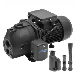
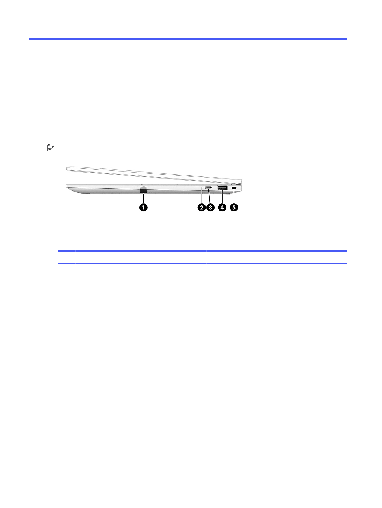
Right
Use this illustration and table to identify the components on the right side of the computer.
NOTE: Refer to the illustration that most closely matches your computer.
Table 2-1
Right-side components and their descriptions
Component Description
(1) Garaged pen Holds an optional pen.
(2) Battery light When AC power is connected:
● White: The battery charge is greater than 90%.
● Amber: The battery charge is from 0 to 90%.
● Off: The battery is not charging.
When AC power is disconnected (battery not charging):
● Blinking amber: The battery has reached a low battery
level. When the battery has reached a critical battery
level, the battery light begins blinking rapidly.
● Off: The battery is not charging.
(3) USB Type-C® 10 Gbps port Connects a display device that has a USB Type-C connector
providing DisplayPort output.
NOTE: Use a standard USB Type-C charging cable or cable
adapter (purchased separately) when charging a small
external device.
(4) USB port Connects a USB device, provides high-speed data transfer,
and charges small devices (such as a smartphone).
NOTE: Use a standard USB Type-A charging cable or cable
adapter (purchased separately) when charging a small
external device.
6 Chapter 2 Components
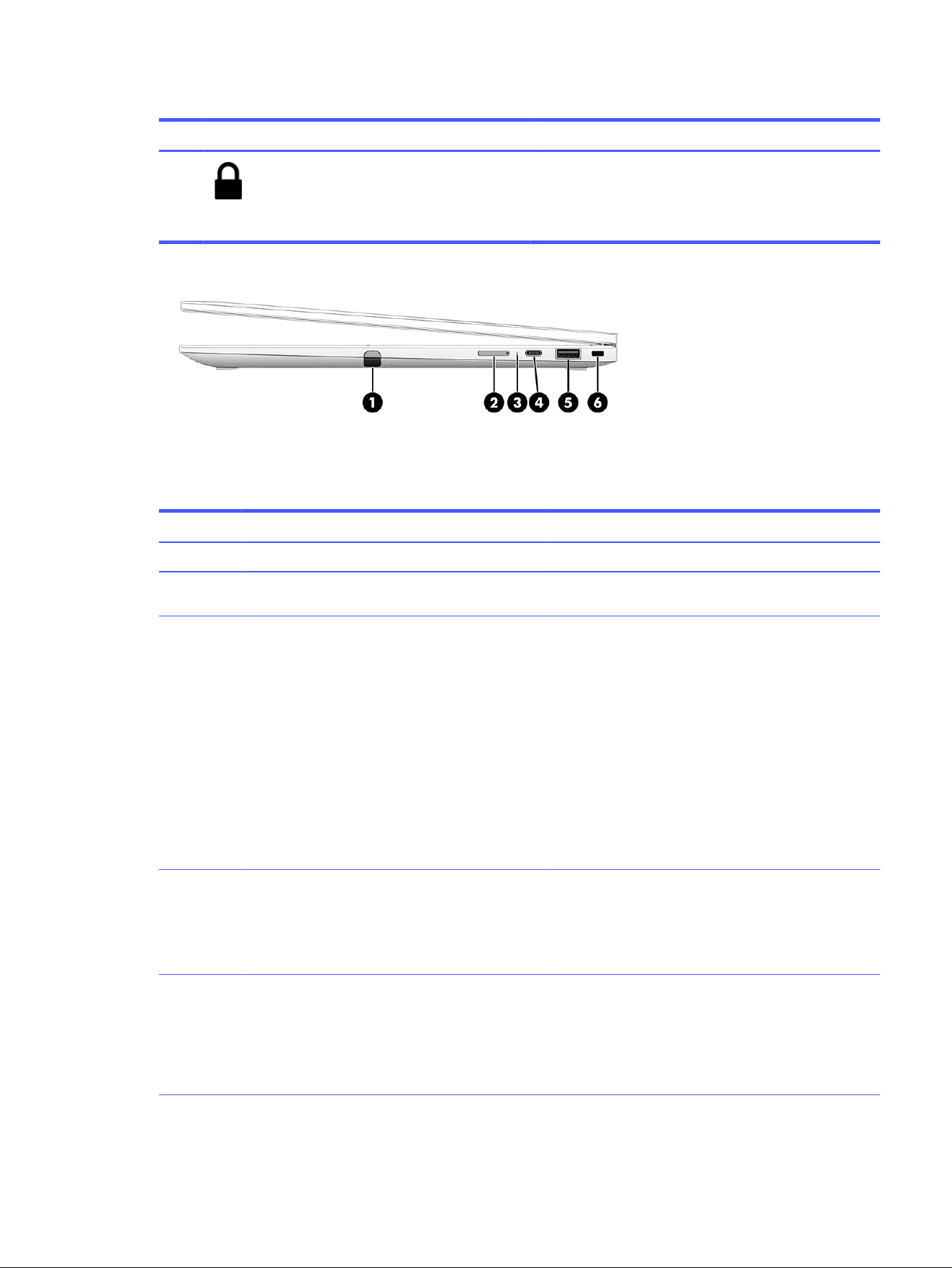
Table 2-1 Right-side components and their descriptions (continued)
Component Description
(5) Security cable slot Attaches an optional security cable to the computer.
NOTE: The security cable is designed to act as a deterrent,
but it might not prevent the computer from being mishandled
or stolen.
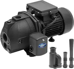
Table 2-2 Right-side components and their descriptions
Component Description
(1) Garaged pen Holds an optional pen.
(2) Nano SIM card slot (select products only) Supports a wireless subscriber identity module (SIM)
card.
(3) Battery light When AC power is connected:
● White: The battery charge is greater than 90%.
● Amber: The battery charge is from 0 to 90%.
● Off: The battery is not charging.
When AC power is disconnected (battery not charging):
● Blinking amber: The battery has reached a low
battery level. When the battery has reached a
critical battery level, the battery light begins blinking
rapidly.
● Off: The battery is not charging.
(4) USB Type-C 10 Gbps port Connects a display device that has a USB Type-C
connector providing DisplayPort output.
NOTE: Use a standard USB Type-C charging cable or
cable adapter (purchased separately) when charging a
small external device.
(5) USB port Connects a USB device, provides high-speed data
transfer, and charges small devices (such as a
smartphone).
NOTE: Use a standard USB Type-A charging cable or
cable adapter (purchased separately) when charging a
small external device.
Right 7
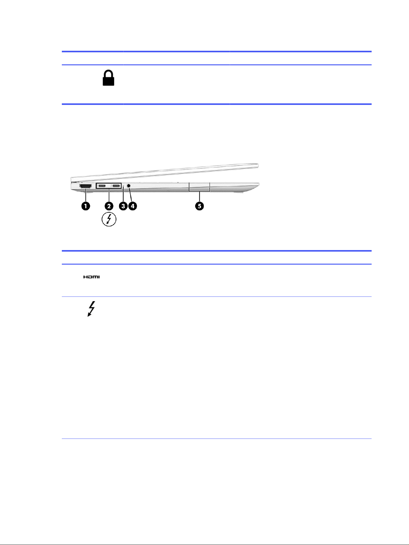
Table 2-2 Right-side components and their descriptions (continued)
Component Description
(6) Security cable slot Attaches an optional security cable to the computer.
NOTE: The security cable is designed to act as a
deterrent, but it might not prevent the computer from
being mishandled or stolen.
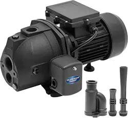
Left
Use this illustration and table to identify the components on the left side of the computer.
Table 2-3
Left-side components and their descriptions
Component Description
(1) HDMI port Connects an optional video or audio device, such as a
high-definition television, any compatible digital or audio
component, or a high-speed High Definition Multimedia
Interface (HDMI) device.
(2) USB Type-C power connector and
Thunderbolt port with HP Sleep and Charge
and DisplayPort output (2)
Connects an AC adapter that has a USB Type-C connector,
supplying power to the computer and, if needed, charging the
computer battery.
– and –
Connects a USB device, provides high-speed data transfer,
and charges small devices (such as a smartphone), even
when the computer is off.
NOTE: Use a standard USB Type-C charging cable or cable
adapter (purchased separately) when charging a small
external device.
– and –
Connects a display device that has a USB Type-C connector,
providing DisplayPort output.
NOTE: Your computer might also support a Thunderbolt
docking station.
8
Chapter 2 Components
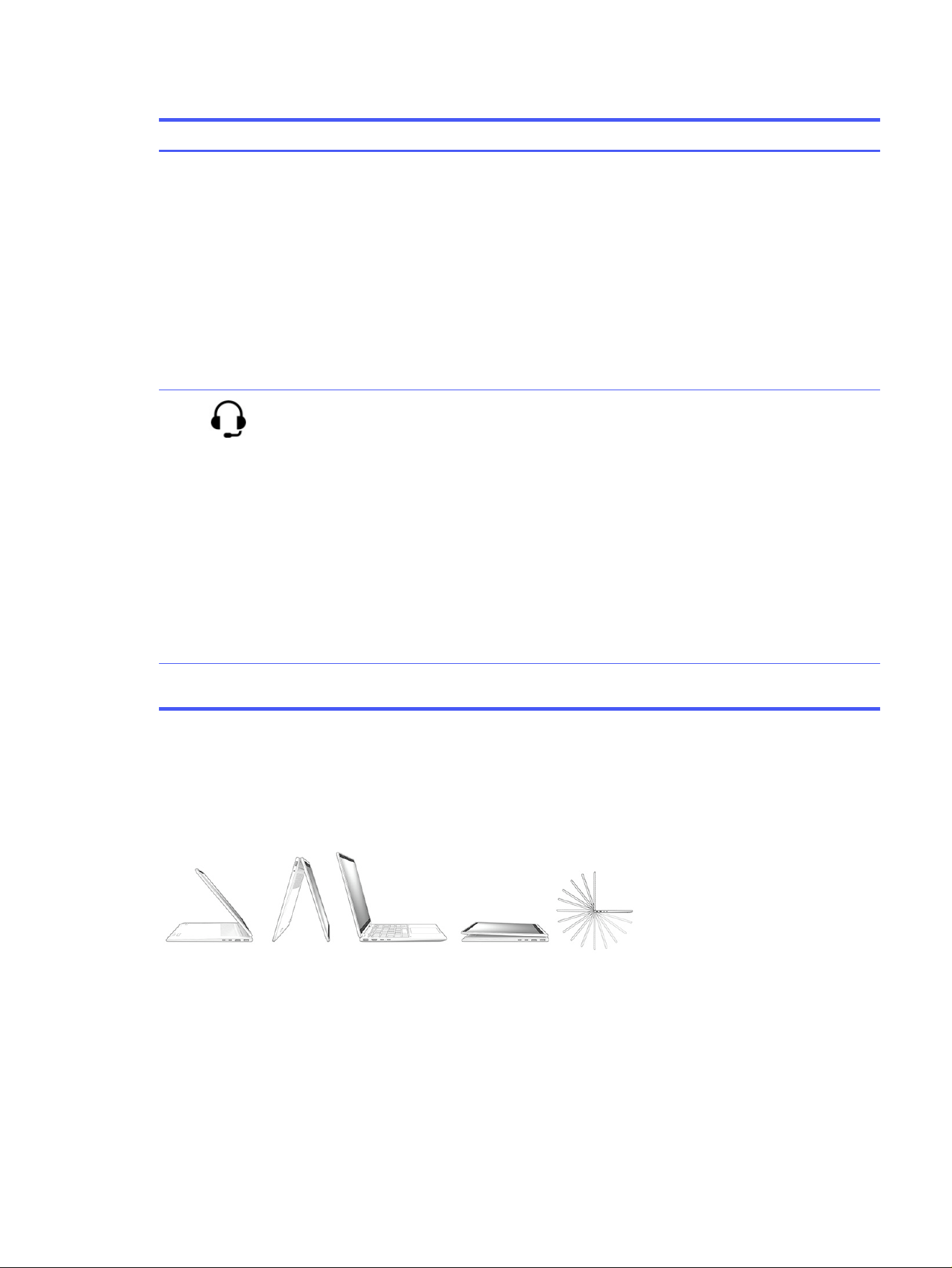
Table 2-3 Left-side components and their descriptions (continued)
Component Description
(3) Battery light When AC power is connected:
● White: The battery charge is greater than 90%.
● Amber: The battery charge is from 0 to 90%.
● Off: The battery is not charging.
When AC power is disconnected (battery not charging):
● Blinking amber: The battery has reached a low battery
level. When the battery has reached a critical battery
level, the battery light begins blinking rapidly.
● Off: The battery is not charging.
(4) Audio-out (headphone)/Audio-in
(microphone) combo jack
Connects optional powered stereo speakers, headphones,
earbuds, a headset, or a television audio cable. Also
connects an optional headset microphone. This jack does
not support optional standalone microphones.
WARNING! To reduce the risk of personal injury, adjust the
volume before putting on headphones, earbuds, or a
headset. For additional safety information, see the
Regulatory, Safety, and Environmental Notices
.
To access this guide:
■
Select the Search icon in the taskbar, type HP
Documentation in the search box, and then select HP
Documentation.
NOTE: When a device is connected to the jack, the
computer speakers are disabled.
(5) WWAN antennas Send and receive wireless signals to communicate with
wireless wide area networks (WWANs).
360 modes (select products only)
If your computer offers 360 modes, the following illustration shows how you can use and fold your
device.
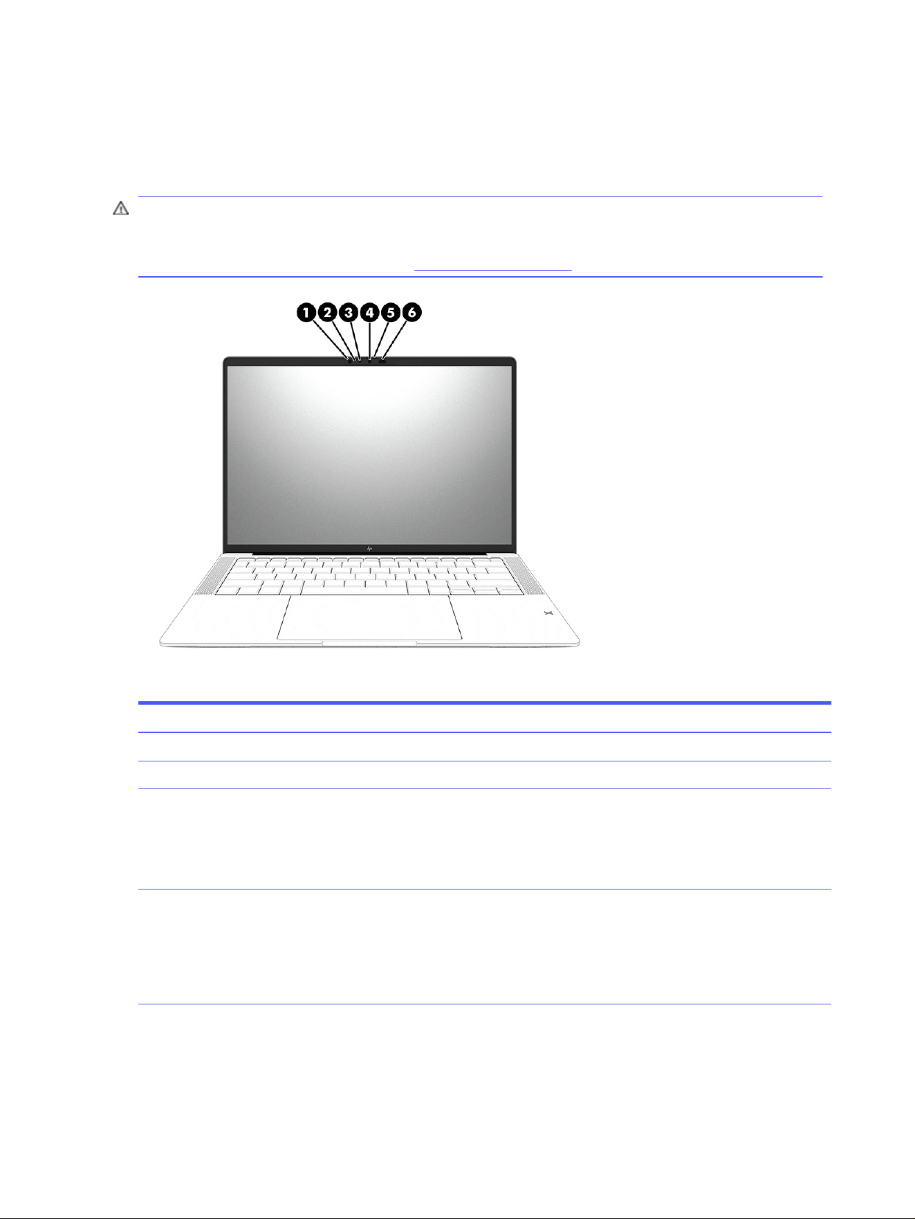
Display
Use this illustration and table to identify the display components.
360 modes (select products only)
9
Low blue light mode (select products only)
Your computer display is shipped from the factory in low blue light mode for improved eye comfort and
safety. Also, blue light mode automatically adjusts blue light emissions when you are using the computer
at night or for reading.
WARNING! To reduce the risk of serious injury, read the
Safety & Comfort Guide
. It describes proper
workstation setup and proper posture, health, and work habits for computer users. The
Safety &
Comfort Guide
also provides important electrical and mechanical safety information. The
Safety &
Comfort Guide
is available on the web at http://www.hp.com/ergo.
Table 2-4 Display components and their descriptions
Component Description
(1) IR Camera light On: The IR camera is in use.
(2) Webcam light On: The webcam is in use.
(3) IR camera Allows you to video chat, record video, and record still images.
Some cameras also allow a facial recognition logon to Windows,
instead of a password logon.
NOTE: Camera functions vary depending on the camera
hardware and software installed on your product.
(4) Webcam Allows you to video chat, record video, and record still images.
Some cameras also allow a facial recognition logon to Windows,
instead of a password logon.
NOTE: Camera functions vary depending on the camera
hardware and software installed on your product.
10 Chapter 2 Components

Table 2-4 Display components and their descriptions (continued)
Component Description
(5) Camera privacy cover By default, the camera lens is uncovered, but you can slide the
camera privacy cover to block the camera’s view. To use the
camera, slide the camera privacy cover in the opposite direction
to reveal the lens.
NOTE: If you have both front-facing and rear-facing cameras,
when one camera lens is revealed and ready to use, the other is
concealed.
(6) Ambient light and color sensor Adjusts the brightness of the display, depending on the ambient
light, and manages and controls the color temperature. Color
temperature enables you to measure and adjust the warmth or
coolness of the light source.
Keyboard area
Keyboards can vary by language.
NOTE: The keyboard, including the function keys and power key (select products only), is disabled in
stand, tent, and tablet modes. To enable the keyboard, including the power key, change to the clamshell
mode.
Touchpad
The touchpad settings and components are described here.
Touchpad settings
You learn how to adjust the touchpad settings and components here.
Adjusting touchpad settings
Use these steps to adjust touchpad settings and gestures.
1. Select the Search icon in the taskbar, type touchpad settings in the search box, and then
press enter.
2. Choose a setting.
Turning on the touchpad
Follow these steps to turn on the touchpad.
1. Select the Search icon in the taskbar, type touchpad settings in the search box, and then
press enter.
2. Using an external mouse, click the Touchpad button.
If you are not using an external mouse, press the Tab key repeatedly until the pointer rests on the
touchpad button. Then press the spacebar to select the button.
Touchpad components
Use this illustration and table to identify the touchpad components.
Keyboard area
11
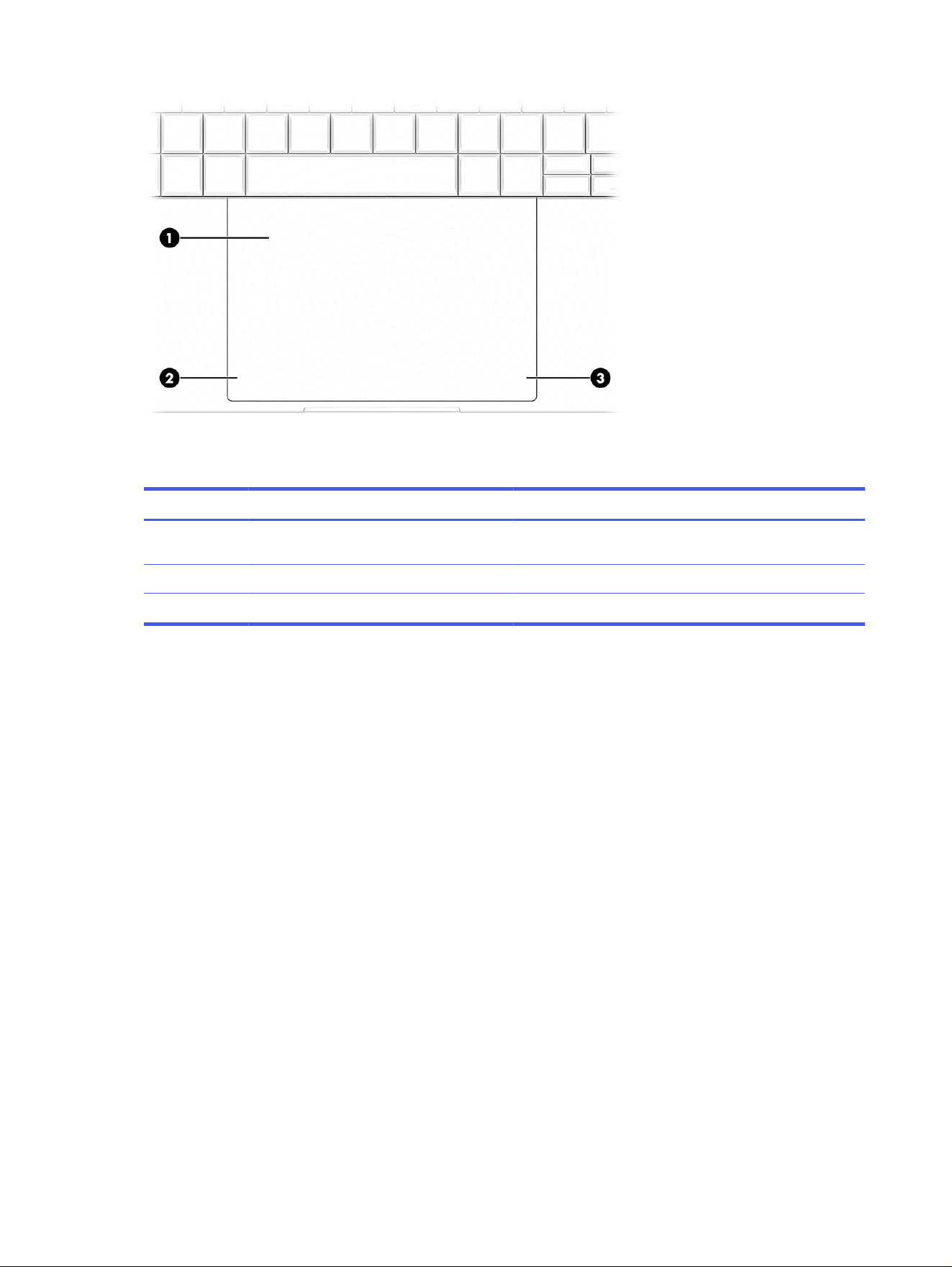
Table 2-5 Touchpad components and their descriptions
Component Description
(1) Touchpad zone Reads your finger gestures to move the pointer or activate
items on the screen.
(2) Left touchpad button Functions like the left button on an external mouse.
(3) Right touchpad button Functions like the right button on an external mouse.
Lights
Use this illustration and table to identify the lights on the computer.
12
Chapter 2 Components
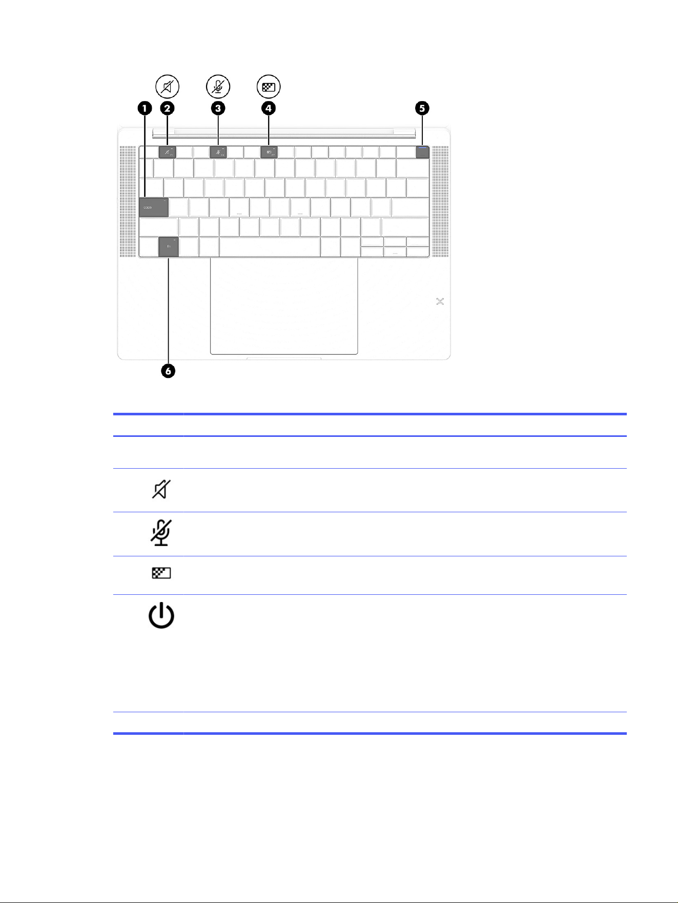
Table 2-6 Lights and their descriptions
Component Description
(1) Caps lock light On: Caps lock is on, which switches the key input to all capital
letters.
(2) Mute light ● On: Computer sound is off.
● Off: Computer sound is on.
(3) Microphone mute light ● On: Microphone is off.
● Off: Microphone is on.
(4) Privacy key light On: Privacy screen is on, which helps prevent side-angle
viewing.
(5) Power light ● On: The computer is on.
● Blinking (select products only): The computer is in
the sleep state, a power-saving state. The computer
shuts off power to the display and other unnecessary
components.
● Off: Depending on your computer model, the computer
is off, in hibernation, or in sleep. Hibernation is the power-
saving state that uses the least amount of power.
(6) Fn lock light On: The fn key is locked.
Lights 13
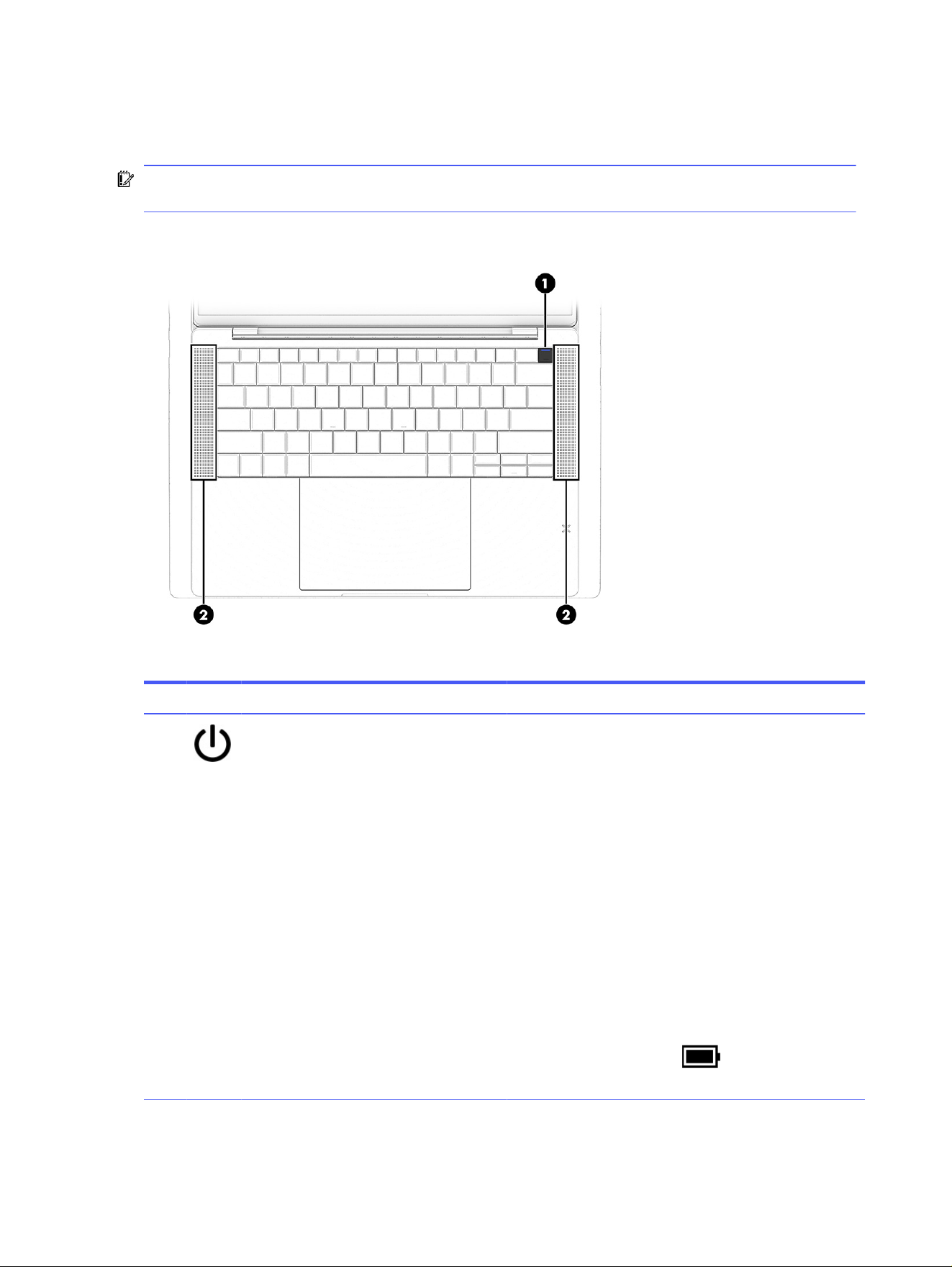
Buttons, speakers, and fingerprint reader
Fingerprint readers are located on the power button.
IMPORTANT: To verify that your computer supports fingerprint reader sign-in, select the Search icon
in the taskbar, type Sign-in options in the search box, and then select the Sign-on options app.
Table 2-7 Buttons, speakers, and fingerprint reader and their descriptions
Component Description
(1) Power button ● When the computer is off, press the button briefly to turn
on the computer.
● When the computer is on, press the button briefly to
initiate sleep.
● When the computer is in the sleep state, press the button
briefly to exit sleep (select products only).
● When the computer is in hibernation, press the button
briefly to exit hibernation.
IMPORTANT: Pressing and holding down the power button
results in the loss of unsaved information.
If the computer has stopped responding and shut down
procedures are ineffective, press and hold the power button
for at least 10 seconds to turn off the computer.
To learn more about your power settings, use the Power icon.
■
Right-click the Power icon , and then select Power
and sleep settings.
14
Chapter 2 Components
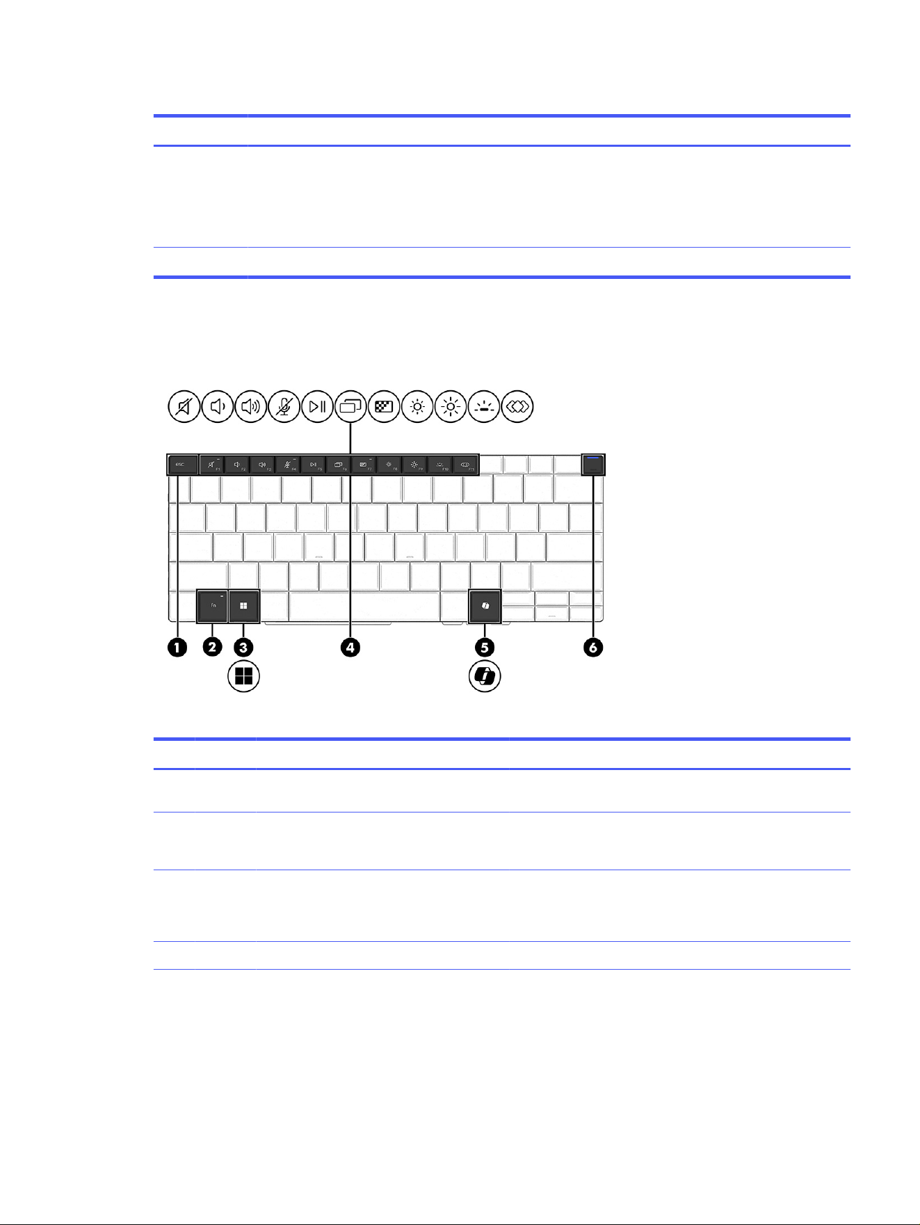
Table 2-7 Buttons, speakers, and fingerprint reader and their descriptions (continued)
Component Description
(1) Fingerprint reader (select products only) Allows a fingerprint logon to Windows, instead of a password
logon.
IMPORTANT: To prevent fingerprint logon issues, make sure
when you register your fingerprint that all sides of your finger
are registered by the fingerprint reader.
(2) Speakers Produce sound.
Special keys
Use this illustration and table to identify the special keys.
Table 2-8
Special keys and their descriptions
Component Description
(1) esc key Displays system information when pressed in combination
with the fn key.
(2) fn key Executes frequently used system functions when pressed in
combination with another key. Such key combinations are
called
hot keys
.
(3) Windows key Opens the Start menu.
NOTE: Pressing the Windows key again will close the Start
menu.
(4) Action keys Execute frequently used system functions.
Special keys 15
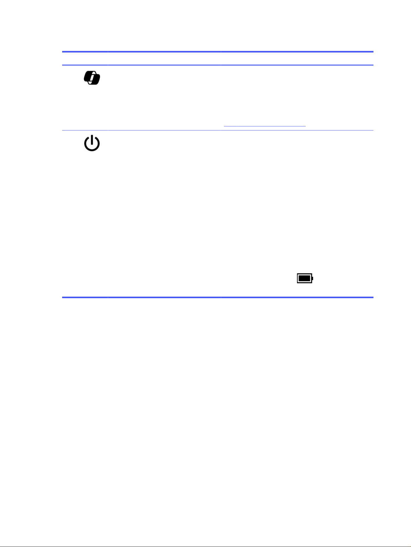
Table 2-8 Special keys and their descriptions (continued)
Component Description
(5) Windows Copilot key Opens Windows Copilot (select products only).
NOTE: Copilot in Windows (select products only) requires
Windows 11. Some features require a neural processing unit
(NPU). The timing of feature delivery and availability varies by
market and device. You must have a Microsoft account to use
the Copilot feature. When the Copilot feature is not available,
pressing the Copilot key opens the Bing search engine. See
http://aka.ms/WindowsAIFeatures.
(6) Power button ● When the computer is off, press the button briefly to
turn on the computer.
● When the computer is on, press the button briefly to
initiate sleep.
● When the computer is in the sleep state, press the
button briefly to exit sleep (select products only).
● When the computer is in hibernation, press the button
briefly to exit hibernation.
IMPORTANT: Pressing and holding down the power button
results in the loss of unsaved information.
If the computer has stopped responding and shut down
procedures are ineffective, press and hold the power button
for at least 10 seconds to turn off the computer.
To learn more about your power settings, use the Power icon.
■
Right-click the Power icon , and then select Power
and sleep settings.
Bottom
Use this illustration and table to identify the bottom components.
16
Chapter 2 Components
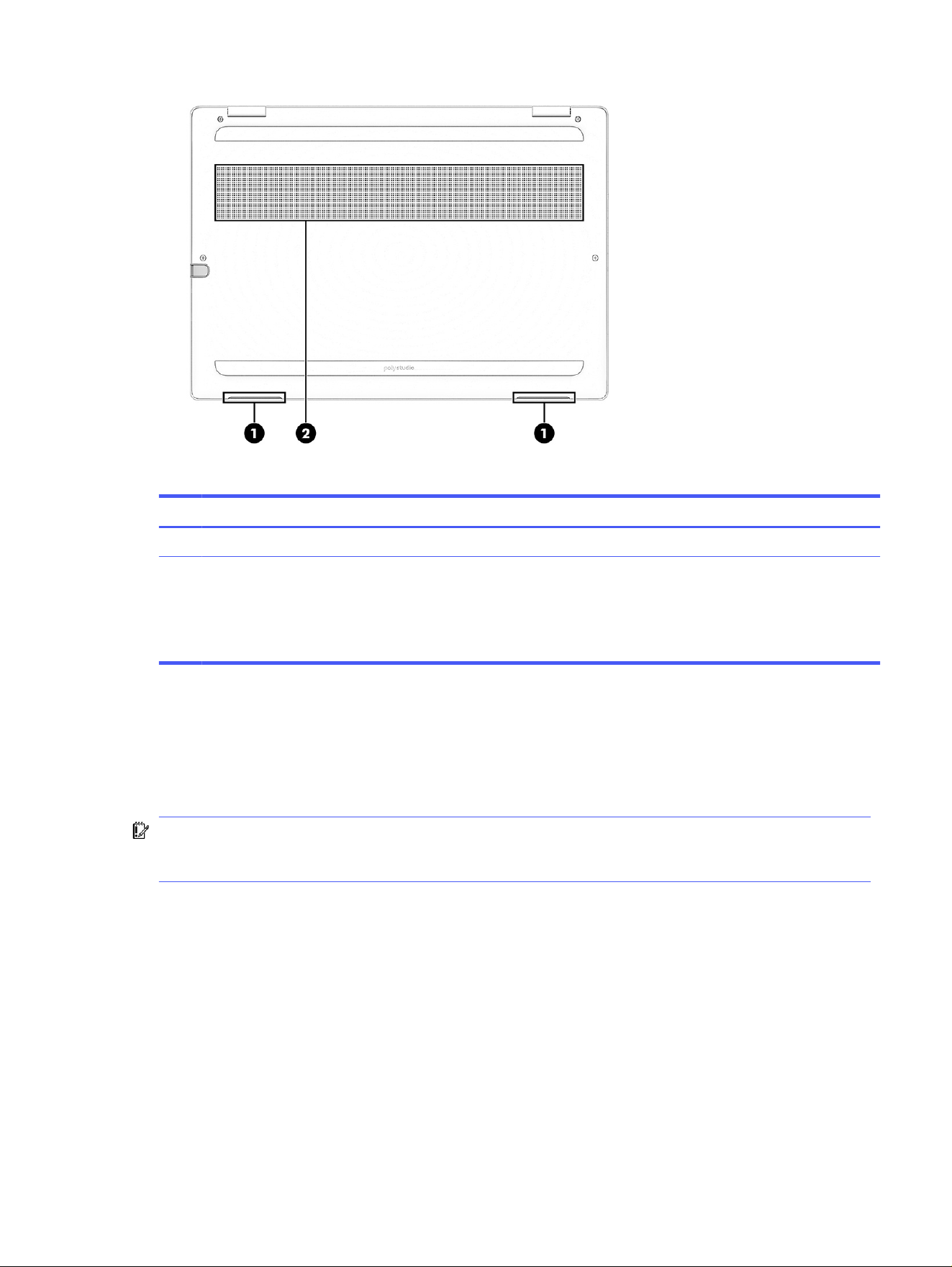
Table 2-9 Bottom components and their descriptions
Component Description
(1) Speakers Produce sound.
(2) Vent Enables airflow to cool internal components.
NOTE: The computer fan starts up automatically to
cool internal components and prevent overheating. It is
normal for the internal fan to cycle on and off during
routine operation.
Labels
The labels affixed to the computer provide information you might need when you troubleshoot system
problems or travel internationally with the computer. Labels might be in paper form or imprinted on the
product.
IMPORTANT: Check the following locations for the labels described in this section: the bottom of the
computer, inside the battery bay, under the service door, on the back of the display, or on the bottom of
a tablet kickstand.
● Regulatory labels—Provide regulatory information about the computer.
● Wireless certification labels—Provide information about optional wireless devices and the approval
markings for the countries or regions in which the devices have been approved for use.
● Service label—Provides important information to identify your computer. When contacting support,
you might be asked for the serial number, the product number, or the model number. Locate this
information before you contact support.
Your service label will resemble one of the examples shown below. Refer to the illustration that most
closely matches the service label on your computer.
Labels
17
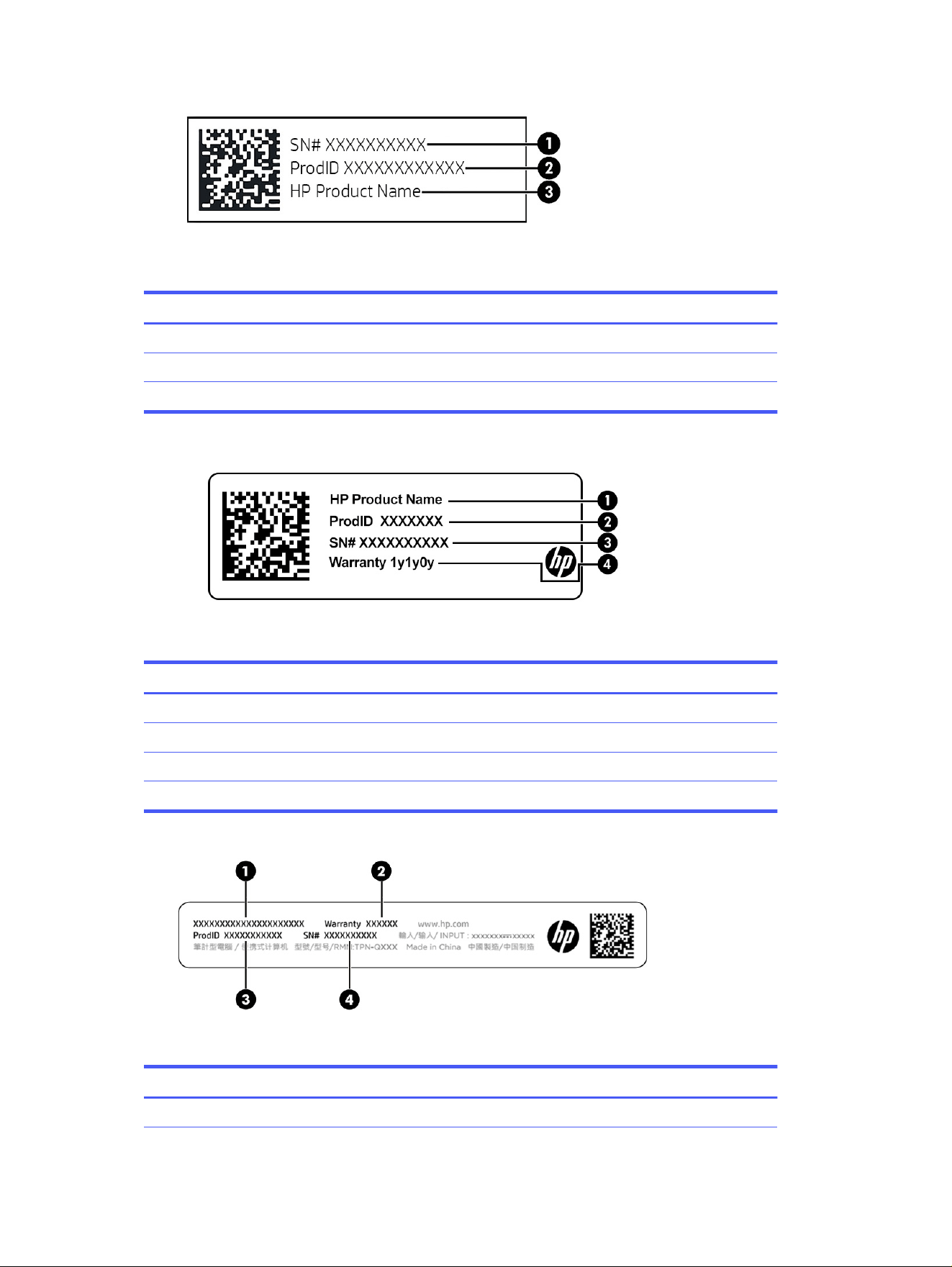
Table 2-10 Service label components
Component
(1) Serial number
(2) Product ID
(3) HP product name
Table 2-11 Service label components
Component
(1) HP product name
(2) Product ID
(3) Serial number
(4) Warranty period
Table 2-12 Service label components
Component
(1) HP product name
18 Chapter 2 Components

Table 2-12 Service label components (continued)
Component
(2) Warranty period
(3) Product ID
(4) Serial number
NOTE: This is a sample QR code. Scan the QR code located on the bottom of your product for
serial-number specific information about setting up and using the product, as well as access to
support information.
Using a SIM card (select products only)
Use these instructions to insert a SIM card.
IMPORTANT: You can damage the SIM card if you insert the wrong size card or insert it or the SIM
card tray in the wrong direction. The card might also become stuck in the slot. Do not use SIM card
adapters. To prevent damage to the SIM card or connectors, use minimal force when inserting or
removing a SIM card.
Determining the correct SIM card size for your computer
Before purchasing a SIM card, follow these instructions to determine the correct SIM card size for your
computer.
1. Go to http://www.hp.com/support, and then search for your computer by product name or number.
2. Select Product Information.
3. Refer to the listed options to determine which card to purchase.
Inserting a nano SIM card
To insert a nano SIM card, follow these steps.
1. Turn off the computer by using the Shut down command.
2. Position the computer display-side up on a flat surface.
3. Insert a small straightened paper clip into the card tray access hole.
4. Press in gently on the paper clip until the card tray is ejected (1).
5. Remove the tray (2) from the computer and insert the card (3).
Using a SIM card (select products only)
19
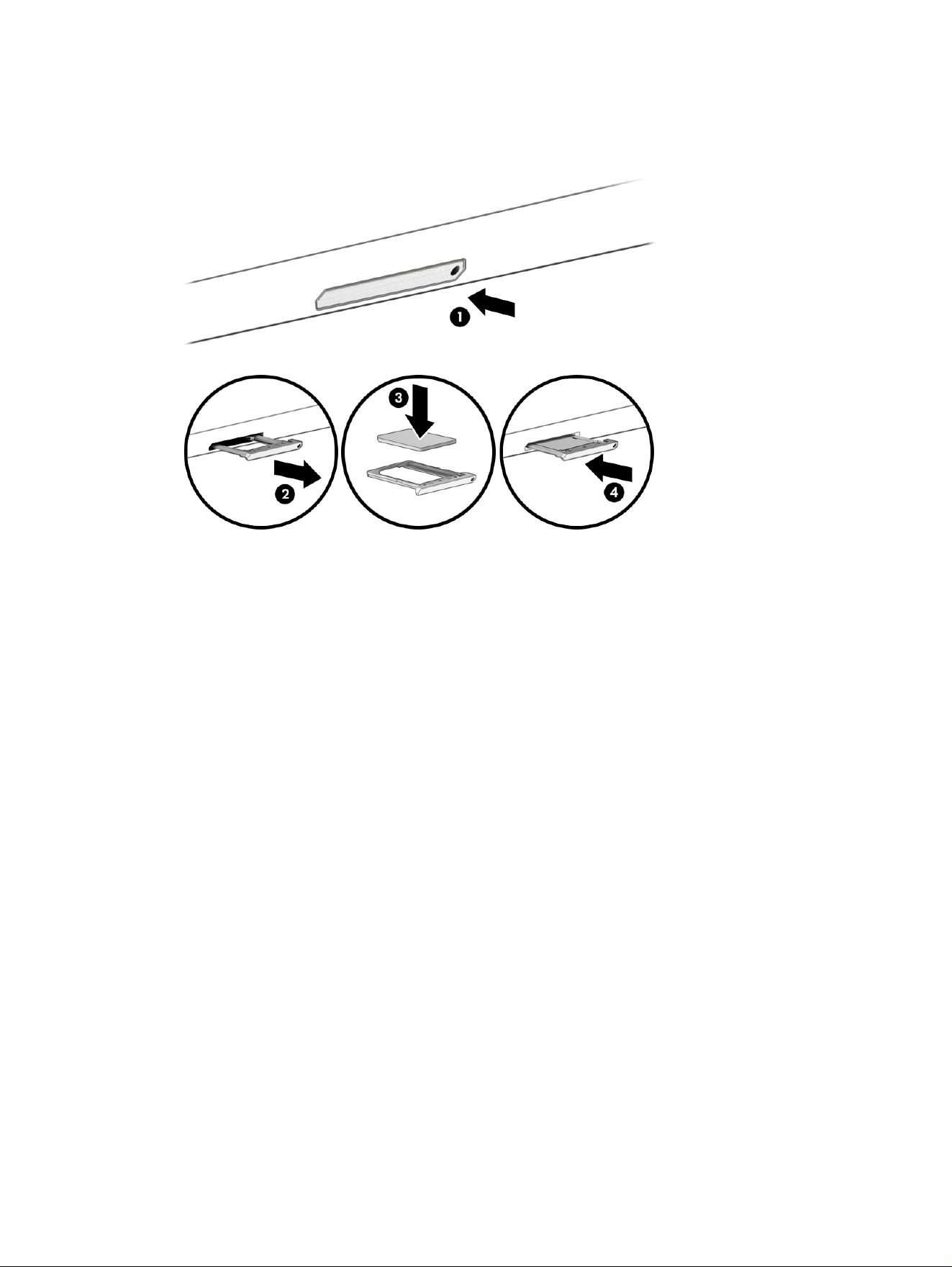
6. Replace the tray in the computer. Press in gently on the tray (4) until it is firmly seated.
To remove the SIM card, press in gently on the SIM card access tray to disengage the SIM lock, and the
tray will pop out of the slot. Remove the SIM card. Replace the tray in the computer and press in gently
on the tray until it is firmly seated.
20
Chapter 2 Components
Illustrated parts catalog3
Use this chapter to determine the spare parts that are available for the computer.
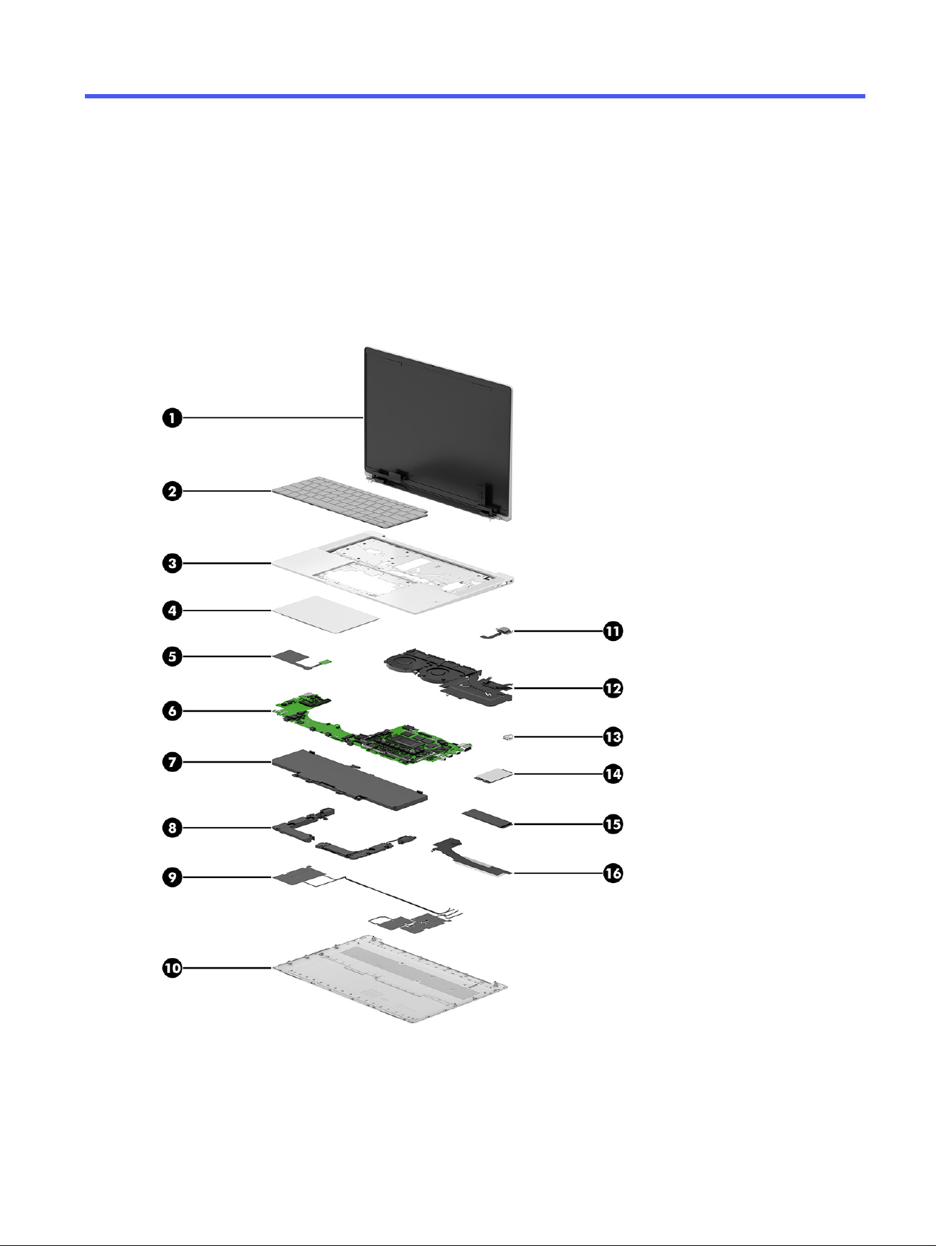
Computer major components
Use this illustration and table to identify the computer major components.
Illustrated parts catalog 21

Table 3-1 Computer major component descriptions and part numbers
Item Component CSR category* Spare part number
(1) Display assembly (full hinge up)
2.8 K, OLED, 700 nits, antiglare, glacier silver models N P90104-001
2.8 K, OLED, 700 nits, antiglare, atmospheric blue models N P90102-001
2.8 K, OLED, 500 nits, antiglare, glacier silver models N P90092-001
2.8 K, OLED, 500 nits, antiglare, atmospheric blue models N P90090-001
WUXGA, 800 nits, antiglare, atmospheric blue models N P90074-001
WUXGA, 800 nits, antiglare, glacier silver models N P90076-001
WUXGA, 800 nits, BrightView, atmospheric blue models N P90086-001
WUXGA, 800 nits, BrightView, glacier silver models N P90088-001
WUXGA, 400 nits, antiglare, atmospheric blue models N P90078-001
WUXGA, 400 nits, antiglare, glacier silver models N P90080-001
WUXGA, 400 nits, BrightView, atmospheric blue models N P90084-001
WUXGA, 400 nits, BrightView, glacier silver models N P90082-001
WUXGA, 300 nits, antiglare, atmospheric blue models N P90096-001
WUXGA, 300 nits, antiglare, glacier silver models N P90094-001
WUXGA, 300 nits, BrightView, atmospheric blue models N P90098-001
WUXGA, 300 nits, BrightView, glacier silver models N P90100-001
(2) Keyboard
NOTE: For a detailed list of country codes, see Top cover on page
73.
Atmospheric blue B P86838-xx1
Atmospheric blue, privacy B P86839-xx1
Glacier silver B P86840-xx1
Glacier silver, privacy B P86841-xx1
(3) Top cover
Glacier silver, models without WWAN, no pen N P86647-001
Glacier silver, models without WWAN, with pen N P86648-001
Glacier silver, models with WWAN, no pen N P86649-001
Glacier silver, models with WWAN, with pen N P86650-001
Atmospheric blue, models without WWAN, no pen N P86651-001
Atmospheric blue, models without WWAN, with pen N P86652-001
Atmospheric blue, models with WWAN, no pen N P86653-001
Atmospheric blue, models with WWAN, with pen N P86654-001
(4) Touchpad (includes cable) N
22 Chapter 3 Illustrated parts catalog

Table 3-1 Computer major component descriptions and part numbers (continued)
Item Component CSR category* Spare part number
Click, glacier silver N P87574-001
Click, glacier silver, with NFC N P87575-001
Click, atmospheric blue N P87576-001
Click, atmospheric blue, with NFC N P87577-001
Haptic, glacier silver N P87580-001
Haptic, glacier silver, with NFC N P87581-001
Haptic, atmospheric blue N P87582-001
Haptic, atmospheric blue, with NFC N P87583-001
(5) NFC module (with antenna) N M08706-001
(6) System board (includes processor and system memory)
Intel Core Ultra X7 368H processor and 32 GB system memory
(Operating System Recovery [OSR])
N P86390-601
Intel Core Ultra X7 358H processor and 64 GB system memory N P86386-601
Intel Core Ultra X7 358H processor and 64 GB system memory (PRC) N P86389-601
Intel Core Ultra X7 358H processor and 32 GB system memory N P86385-601
Intel Core Ultra X7 358H processor and 32 GB system memory (PRC) N P86388-601
Intel Core Ultra 7 366H processor and 64 GB system memory N P86387-601
Intel Core Ultra 7 366H processor and 32 GB system memory N P86375-601
Intel Core Ultra 7 366H processor and 32 GB system memory (PRC) N P86376-601
Intel Core Ultra 7 366H processor and 32 GB system memory (OSR) N P86374-601
Intel Core Ultra 7 366H processor and 24 GB system memory N P86373-601
Intel Core Ultra 7 356H processor and 32 GB system memory N P86371-601
Intel Core Ultra 7 356H processor and 32 GB system memory (PRC) N P86372-601
Intel Core Ultra 7 356H processor and 24 GB system memory N P86384-601
Intel Core Ultra 5 338H processor and 32 GB system memory (OSR) N P86382-601
Intel Core Ultra 5 338H processor and 32 GB system memory (PRC) N P86383-601
Intel Core Ultra 5 335 and 32 GB system memory N P86380-601
Intel Core Ultra 5 335 and 32 GB system memory (OSR) N P86379-601
Intel Core Ultra 5 335 and 32 GB system memory (PRC) N P86381-601
Intel Core Ultra 5 335 and 24 GB system memory N P86370-601
Intel Core Ultra 5 335 and 16 GB system memory N P86369-601
Intel Core Ultra 5 325 and 32 GB system memory N P86378-601
Intel Core Ultra 5 325 and 24 GB system memory N P86368-601
Intel Core Ultra 5 325 and 24 GB system memory (PRC) N P86377-601
Intel Core Ultra 5 325 and 16 GB system memory N P86367-601
Computer major components 23

Table 3-1 Computer major component descriptions and part numbers (continued)
Item Component CSR category* Spare part number
(7) Battery (includes revive kit)
Battery (6 cell, 68 Wh) A P92640-001
Battery (3 cell, 56 Wh) A P92639-001
(8) Speakers (left and right) P86637-001
(9) WWAN antennas N P86665-001
(10) Bottom cover
Glacier silver, models without WWAN, no pen A P86655-001
Glacier silver, models without WWAN, with pen A P86656-001
Glacier silver, models with WWAN, no pen A P86657-001
Glacier silver, models with WWAN, with pen A P86658-001
Atmospheric blue, models without WWAN, no pen A P86659-001
Atmospheric blue, models without WWAN, with pen A P86660-001
Atmospheric blue, models with WWAN, no pen A P86661-001
Atmospheric blue, models with WWAN, with pen A P86662-001
(11) Power button board/fingerprint reader (includes cable)
Glacier silver N P87592-001
Atmospheric blue N P87593-001
(12) Fan/heat sink assembly N P86638-001
(13) Nano lock bracket N 918431-001
(14) WWAN module
HP R15 5G Solution N P06930-001
HP R15 5G Solution with HP Go N P26028-001
HP RW220-GL LTE (CAT-1bis) (low power) N P47161-001
HP R18 5G Solution N P62206-001
HP R18 5G Solution with HP Go N P62207-001
(15) SSD
2 TB, PCIe-5 × 4, nM A P41682-001
2 TB, PCIe-5 × 4, value A P73031-001
2 TB, PCIe-5 × 4, self-encrypting drive (SED) A P90258-001
1 TB, PCIe-4 × 4, value A N77394-001
1 TB, PCIe-5 × 4, nM A P32587-001
1 TB, PCIe-5 × 4 A P73030-001
1 TB, PCIe-5 × 4, SED A P90257-001
512 GB, PCIe-4 × 4, value A N44321-001
24 Chapter 3 Illustrated parts catalog

Table 3-1 Computer major component descriptions and part numbers (continued)
Item Component CSR category* Spare part number
512 GB, PCIe-5 × 4 A P73029-001
512 GB, PCIe-5 × 4, SED A P86946-001
(16) SSD/WWAN module heat sink N P87602-001
Table 3-2 CSR part categories*
Category Description Replacement responsibility
CSR A Self-service parts Customers can replace these easily replaceable parts.
Replacement by trained technicians might incur additional cost.
CSR B/C Optional self-service parts Skilled customers can replace these parts. Warranty replacement
available via trained technicians.
CSR N Non-self-service parts Only trained service technicians should replace these complex
parts.
Miscellaneous parts
Use this table to identify the miscellaneous parts.
Table 3-3
Miscellaneous part descriptions and part numbers
Component Spare part number
Screw Kit P87606-001
Cable Kit (includes cables for the ACS, camera, microphone module, NFC module, hub board,
fingerprint reader, and touchpads)
P86636-001
Misc Parts Kit (includes middle hook, WLAN protective tape, thermal pads, gaskets, tapes, WWAN
rubber spacer, top I/O holders, insulators, absorbers, SSD bumpers, and foam)
P86663-001
Bracket Kit, glacier silver (includes nano lock bracket, pen bracket, sim tray, and thermal pads) P86641-001
Bracket Kit, atmospheric blue (includes nano lock bracket, pen bracket, sim tray, and thermal pads) P86641-001
Shielding Kit (includes WWAN shield, WLAN shield, SSD shield, SSD foam, and SSD thermal pad) P93176-001
Pen, atmospheric blue P92599-001
Pen, glacier silver P92600-001
Thermal pad Q02317-001
Nano lock 918431-001
HP USB Mouse L95713-001
HP 435 Wireless Mouse M62277-001
HP 715 Rechargeable Multidevice Mouse N21845-001
HP 501/515 Rechargeable Mouse N86885-001
HP 320K Wired Keyboard P24877-901
Adapter
Miscellaneous parts 25

Table 3-3 Miscellaneous part descriptions and part numbers (continued)
Component Spare part number
HP HDMI-to-VGA adapter 701943-001
HP USB-C-to-RJ-45 adapter M95985-001
HP USB-C-to-DisplayPort adapter N81435-001
HP USB-C-to-HDMI adapter 2.0 935325-001
HP USB 3.0-to-gigabit RJ-45 M95984-001
USB adapter BT700 adapter N46131-001
Poly Voyager 4320 Headset N57159-001
Poly Voyager Free 60 UC Headset N73088-001
HP Business 14.1 Laptop Case M55007-001
HP Executive 16 Laptop Bag N19980-001
HP Executive 16 Laptop Backpack N19979-001
HP Prelude Pro 15.6 Top Load Case M03618-001
HP Prelude Pro 15.6 Backpack M03617-001
Hub
USB Type-C G3, multiport, travel hub N60372-001
HP USB Type-C universal multiport hub M96882-001
Docking stations
HP Thunderbolt 4 100 W G6 Dock (with WLAN) P34015-001
HP Thunderbolt 4 100 W G6 Dock (without WLAN) (TAA) P34016-001
HP Thunderbolt 4 180 W G6 Dock (with WLAN) P34009-001
HP Thunderbolt 4 180 W G6 Dock (without WLAN) (TAA) P34010-001
HP Thunderbolt 4 280 W G6 Dock (with WLAN) P34012-001
HP Thunderbolt 4 280 W G6 Dock (with WLAN) (TAA) P34013-001
HP USB-C 100 W G6 dock P62168-001
HP USB-C 100 W G6 dock (TAA) P62169-001
Bottom case for use with Thunderbolt 4 G6 docking station P34055-001
Top cover for use with Thunderbolt 4 G6 docking station P34054-001
Cable Kit for use with Thunderbolt 4 100 W/180 W G6 docking station P34060-001
Cable Kit for use with Thunderbolt 4 280 W G6 docking station P34061-001
Cable Kit for use with USB-C 100 W USB-C G6 docking station P62172-001
PCA board for use with Thunderbolt 4/USB-C G6 docking station (models with WLAN) P34056-001
PCA board for use with Thunderbolt 4 G6 docking station (models without WLAN) P34057-001
Power button for use with USB-C G6 docking station P62170-001
Power button for use with Thunderbolt 4 G6 docking station P34106-001
26 Chapter 3 Illustrated parts catalog

Table 3-3 Miscellaneous part descriptions and part numbers (continued)
Component Spare part number
Fan for use with Thunderbolt 4 100 W G6 docking station P34059-001
Fan for use with Thunderbolt 4 180 W/280 W G6 docking station P34058-001
Screw Kit for use with Thunderbolt 4 G6 docking station P34017-001
HP USB External DVD±RW Drive 747080-001
AC adapter
330 W, PFC, smart, 4.5 mm, 3 pin N80119-001
230 W, PFC, smart, 4.5 mm, 3 pin N84766-001
120 W, PRC, smart, slim, 4.5 mm M95377-001
100 W, USB-C, GaN, 2 pin, wall mount, 2.0 m (6.5 ft), FD P58631-001
100 W, USB-C, GaN, 2 pin, wall mount, 2.0 m (6.5 ft), FX P58632-001
65 W, USB-C, GaN, 2 pin, wall mount, 2.0 m (6.5 ft), FX P58629-001
65 W, USB-C, GaN, 2 pin, wall mount, 2.0 m (6.5 ft), FD P58630-001
65 W, USB-C, standard, straight P38779-001
65 W, USB-C, wall mount, 2 pin P68491-001
Power cords (C5, conventional, straight, 1.0 m [3.3 ft])
Argentina L19357-001
Australia L19358-001
Denmark L19360-001
Europe (Austria, Belgium, Finland, France, Germany, the Netherlands, Norway, and Sweden) L19361-001
India L19363-001
Israel L19362-001
Italy L19364-001
Japan L19365-001
North America L19367-001
PRC L19368-001
South Africa L19369-001
South Korea L19366-001
Switzerland L19370-001
Taiwan L19372-001
Thailand L19371-001
Thailand (bundle) M85418-001
United Kingdom L19373-001
Power cord (C13, 1.8 m [6.0 ft], straight, premium)
For use in Argentina L22104-001
Miscellaneous parts 27

Table 3-3 Miscellaneous part descriptions and part numbers (continued)
Component Spare part number
For use in Australia L22339-001
For use in Brazil L57198-001
For use in Denmark L22334-001
For use in Europe L22333-001
For use in India L22343-001
For use in Israel L22335-001
For use in Italy L22103-001
For use in Japan L22344-001
For use in North America L22331-001
For use in South Africa L22337-001
For use in South Korea L22340-001
For use in Switzerland L22336-001
For use in Taiwan L22342-001
For use in Thailand L22338-001
For use in Thailand (bundle) M85413-001
For use in the United Kingdom L22332-001
Duckhead power cord (non-standard, halogen free)
Argentina P57788-001
Australia P57784-001
Europe (Austria, Belgium, Finland, France, Germany, the Netherlands, Norway, and Sweden) P57782-001
India P57790-001
Japan L33157-001
PRC P57787-001
South Korea P57785-001
Thailand P57786-001
United Kingdom P57783-001
28 Chapter 3 Illustrated parts catalog

Removal and replacement procedures
preliminary requirements
4
Use this information to properly prepare to disassemble and reassemble the computer.
Tools required
You need the following tools to complete the removal and replacement procedures.
● Tweezers
● Nonconductive, nonmarking pry tool
● Magnetic Phillips P1 screwdriver
Service considerations
The following sections include some of the considerations that you must keep in mind during
disassembly and assembly procedures.
NOTE: As you remove each subassembly from the computer, place the subassembly and all
accompanying screws away from the work area to prevent damage.
Plastic parts
Using excessive force during disassembly and reassembly can damage plastic parts.
Cables and connectors
Handle cables with extreme care to avoid damage.
IMPORTANT: When servicing the computer, be sure that cables are placed in their proper locations
during the reassembly process. Improper cable placement can damage the computer.
Apply only the tension required to unseat or seat the cables during removal and insertion. Handle cables
by the connector whenever possible. In all cases, avoid bending, twisting, or tearing cables. Be sure that
cables are routed so that they cannot be caught or snagged as you remove or replace parts. Handle flex
cables with extreme care; these cables tear easily.
Drive handling
Note the following guidelines when handling drives.
IMPORTANT: Drives are fragile components. Handle them with care. To prevent damage to the
computer, damage to a drive, or loss of information, observe these precautions:
● Before removing or inserting a hard drive, shut down the computer. If you are unsure whether
the computer is off or in hibernation or sleep mode, turn the computer on, and then shut it down
through the operating system.
Removal and replacement procedures preliminary requirements
29

● Before handling a drive, be sure that you are discharged of static electricity. While handling a drive,
avoid touching the connector.
● Before removing an optical drive, be sure that a disc is not in the drive, and be sure that the optical
drive tray is closed.
● Handle drives on surfaces covered with at least 2.54 cm (1 inch) of shock-proof foam.
● Avoid dropping drives from any height onto any surface.
● After removing a hard drive or an optical drive, place it in a static-proof bag.
● Avoid exposing an internal hard drive to products that have magnetic fields, such as monitors or
speakers.
● Avoid exposing a drive to temperature extremes or liquids.
● If a drive must be mailed, place the drive in a bubble pack mailer or other suitable form of
protective packaging, and label the package “FRAGILE.”
Electrostatic discharge information
A sudden discharge of static electricity from your finger or other conductor can destroy static-sensitive
devices or microcircuitry. Often the spark is neither felt nor heard, but damage occurs. An electronic
device exposed to electrostatic discharge (ESD) might not appear to be affected at all and can work
perfectly throughout a normal cycle. The device might function normally for a while, but it has been
degraded in the internal layers, reducing its life expectancy.
Networks built into many integrated circuits provide some protection, but in many cases, the discharge
contains enough power to alter device parameters or melt silicon junctions.
IMPORTANT: To prevent damage to the device when you remove or install internal components,
observe these precautions:
● Keep components in their electrostatic-safe containers until you are ready to install them.
● Before touching an electronic component, discharge static electricity by using the guidelines
described in Personal grounding methods and equipment on page 31.
● Avoid touching pins, leads, and circuitry. Handle electronic components as little as possible.
● If you remove a component, place it in an electrostatic-safe container.
Generating static electricity
Follow these static electricity guidelines.
● Different activities generate different amounts of static electricity.
● Static electricity increases as humidity decreases.
30
Chapter 4 Removal and replacement procedures preliminary requirements

Table 4-1 Static electricity occurrence based on activity and humidity
Event 55% relative
humidity
40% relative
humidity
10% relative
humidity
Walking across carpet
Walking across vinyl floor
Motions of bench worker
Removing dual in-line packages (DIPs) from plastic tube
7500 V
3000 V
400 V
400 V
15,000 V
5000 V
800 V
700 V
35,000 V
12,000 V
6000 V
2000 V
Removing DIPs from vinyl tray
Removing DIPs from polystyrene foam
Removing bubble pack from PCB (printed circuit board)
Packing PCBs in foam-lined box
2000 V
3500 V
7000 V
5000 V
4000 V
5000 V
20,000 V
11,000 V
11,500 V
14,500 V
26,500 V
21,000 V
NOTE: Multiple electric components can be packaged together in plastic tubes, trays, or polystyrene
foam.
NOTE: As little as 700 V of static electricity can degrade a product.
Preventing electrostatic damage to equipment
Many electronic components are sensitive to ESD. Circuitry design and structure determine the degree
of sensitivity.
The following packaging and grounding precautions are necessary to prevent static electricity damage
to electronic components:
● To avoid hand contact, transport products in static-safe containers such as tubes, bags, or boxes.
● Protect all electrostatic parts and assemblies with conductive or approved containers or packaging.
● Keep electrostatic-sensitive parts in their containers until they arrive at static-free stations.
● Place items on a grounded surface before removing them from their container.
● Always be properly grounded when touching a sensitive component or assembly.
● Avoid contact with pins, leads, or circuitry.
● Place reusable electrostatic-sensitive parts from assemblies in protective packaging or conductive
foam.
Personal grounding methods and equipment
Using certain equipment can prevent static electricity damage to electronic components.
● Wrist straps are flexible straps with a maximum of 1 MΩ ±10% resistance in the ground cords. To
provide proper ground, wear a strap snug against bare skin. Verify that the ground cord is connected
and fits snugly into the banana plug connector on the grounding mat or workstation.
● You can use heel straps, toe straps, and boot straps at standing workstations. These straps are
compatible with most types of shoes or boots. On conductive floors or dissipative floor mats, use
them on both feet with a maximum of 1 MΩ ±10% resistance between the operator and ground.
Preventing electrostatic damage to equipment
31

Table 4-2 Static shielding protection levels
Method Voltage
Antistatic plastic
Carbon-loaded plastic
Metalized laminate
1500
7500
15,000
Grounding the work area
To prevent static damage at the work area, follow these precautions.
● Cover the work surface with approved static-dissipative material.
● Use a wrist strap connected to a properly grounded work surface and use properly grounded tools
and equipment.
● Use static-dissipative mats, foot straps, or air ionizers to give added protection.
● Handle electrostatic sensitive components, parts, and assemblies by the case or PCB laminate.
Handle them only at static-free work areas.
● Turn off power and input signals before inserting and removing connectors or test equipment.
● Use fixtures made of static-safe materials when fixtures must directly contact dissipative surfaces.
● Keep the work area free of nonconductive materials, such as ordinary plastic assembly aids and
polystyrene foam.
● Use conductive field service tools, such as cutters, screwdrivers, and vacuums.
● Avoid contact with pins, leads, or circuitry.
Recommended materials and equipment
HP recommends certain materials and equipment to prevent static electricity.
● Antistatic tape
● Antistatic smocks, aprons, or sleeve protectors
● Conductive bins and other assembly or soldering aids
● Conductive foam
● Conductive tabletop workstations with ground cord of 1 MΩ ±10% resistance
● Static-dissipative table or floor mats with hard tie to ground
● Field service kits
● Static awareness labels
● Wrist straps and footwear straps providing 1 MΩ ±10% resistance
● Material handling packages
● Conductive plastic bags
32
Chapter 4 Removal and replacement procedures preliminary requirements

● Conductive plastic tubes
● Conductive tote boxes
● Opaque shielding bags
● Transparent metallized shielding bags
● Transparent shielding tubes
Cleaning your computer
Cleaning your computer regularly removes dirt and debris so that your device continues to operate at its
best. Use the following information to safely clean the external surfaces of your computer.
Enabling HP Easy Clean (select products only)
HP Easy Clean helps you to avoid accidental input while you clean the computer surfaces. This software
disables devices such as the keyboard, touch screen, and touchpad for a preset amount of time so that
you can clean all computer surfaces.
1. Start HP Easy Clean in one of the following ways:
● Select the Start menu, and then select HP Easy Clean.
● Select the HP Easy Clean icon in the taskbar.
● Select Start, and then select the HP Easy Clean tile.
2. Now that your device is disabled for a short period, see Removing dirt and debris from your
computer on page 33 for the recommended steps to clean the high-touch, external surfaces
on your computer. After you remove the dirt and debris, you can also clean the surfaces with a
disinfectant. See Cleaning your computer with a disinfectant on page 34 for guidelines to help
prevent the spread of harmful bacteria and viruses.
Removing dirt and debris from your computer
Here are the recommended steps to clean dirt and debris from your computer.
For computers with wood veneer, see Caring for wood veneer (select products only) on page 35.
1. Wear disposable gloves made of latex (or nitrile gloves, if you are latex-sensitive) when cleaning the
surfaces.
2. Turn off your device and unplug the power cord and other connected external devices. Remove any
installed batteries from items such as wireless keyboards.
CAUTION: To prevent electric shock or damage to components, never clean a product while it is
turned on or plugged in.
3. Moisten a microfiber cloth with water. The cloth should be moist, but not dripping wet.
IMPORTANT: To avoid damaging the surface, avoid abrasive cloths, towels, and paper towels.
Cleaning your computer
33

4. Wipe the exterior of the product gently with the moistened cloth.
IMPORTANT: Keep liquids away from the product. Avoid getting moisture in any openings. If liquid
makes its way inside your HP product, it can cause damage to the product. Do not spray liquids
directly on the product. Do not use aerosol sprays, solvents, abrasives, or cleaners containing
hydrogen peroxide or bleach that might damage the finish.
5. Start with the display (if applicable). Wipe carefully in one direction, and move from the top of the
display to the bottom. Finish with any flexible cables, like power cord, keyboard cable, and USB
cables.
6. Be sure that surfaces have completely air-dried before turning the device on after cleaning.
7. Discard the gloves after each cleaning. Clean your hands immediately after you remove the gloves.
See Cleaning your computer with a disinfectant on page 34 for recommended steps to clean the
high-touch, external surfaces on your computer to help prevent the spread of harmful bacteria and
viruses.
Cleaning your computer with a disinfectant
The World Health Organization (WHO) recommends cleaning surfaces, followed by disinfection, as a
best practice for preventing the spread of viral respiratory illnesses and harmful bacteria.
After cleaning the external surfaces of your computer using the steps in Removing dirt and debris from
your computer on page 33, Caring for wood veneer (select products only) on page 35, or both, you
might also choose to clean the surfaces with a disinfectant. A disinfectant that is within HP’s cleaning
guidelines is an alcohol solution consisting of 70% isopropyl alcohol and 30% water. This solution is also
known as rubbing alcohol and is sold in most stores.
Follow these steps when disinfecting high-touch, external surfaces on your computer:
1. Wear disposable gloves made of latex (or nitrile gloves, if you are latex-sensitive) when cleaning the
surfaces.
2. Turn off your device and unplug the power cord and other connected external devices. Remove any
installed batteries from items such as wireless keyboards.
CAUTION: To prevent electric shock or damage to components, never clean a product while it is
turned on or plugged in.
3. Moisten a microfiber cloth with a mixture of 70% isopropyl alcohol and 30% water. The cloth should
be moist, but not dripping wet.
CAUTION: Do not use any of the following chemicals or any solutions that contain them, including
spray-based surface cleaners: bleach, peroxides (including hydrogen peroxide), acetone, ammonia,
ethyl alcohol, methylene chloride, or any petroleum-based materials, such as gasoline, paint thinner,
benzene, or toluene.
IMPORTANT: To avoid damaging the surface, avoid abrasive cloths, towels, and paper towels.
4. Wipe the exterior of the product gently with the moistened cloth.
IMPORTANT: Keep liquids away from the product. Avoid getting moisture in any openings. If liquid
makes its way inside your HP product, it can cause damage to the product. Do not spray liquids
directly on the product. Do not use aerosol sprays, solvents, abrasives, or cleaners containing
hydrogen peroxide or bleach that might damage the finish.
34
Chapter 4 Removal and replacement procedures preliminary requirements

5. Start with the display (if applicable). Wipe carefully in one direction, and move from the top of the
display to the bottom. Finish with any flexible cables, like power cord, keyboard cable, and USB
cables.
6. Be sure that surfaces have completely air-dried before turning the device on after cleaning.
7. Discard the gloves after each cleaning. Clean your hands immediately after you remove the gloves.
Caring for wood veneer (select products only)
Your product might feature high-quality wood veneer. As with all natural wood products, proper care is
important for best results over the life of the product. Because of the nature of natural wood, you might
see unique variations in the grain pattern or subtle variations in color, which are normal.
● Clean the wood with a dry, static-free microfiber cloth or chamois.
● Avoid cleaning products containing substances such as ammonia, methylene chloride, acetone,
turpentine, or other petroleum-based solvents.
● Do not expose the wood to sun or moisture for long periods of time.
● If the wood becomes wet, dry it by dabbing with an absorbent, lint-free cloth.
● Avoid contact with any substance that might dye or discolor the wood.
● Avoid contact with sharp objects or rough surfaces that might scratch the wood.
See Removing dirt and debris from your computer on page 33 for the recommended steps to clean
the high-touch, external surfaces on your computer. After you remove the dirt and debris, you can also
clean the surfaces with a disinfectant. See Cleaning your computer with a disinfectant on page 34 for
sanitizing guidelines to help prevent the spread of harmful bacteria and viruses.
Packaging and transporting guidelines
Follow these grounding guidelines when packaging and transporting equipment.
● To avoid hand contact, transport products in static-safe tubes, bags, or boxes.
● Protect ESD-sensitive parts and assemblies with conductive or approved containers or packaging.
● Keep ESD-sensitive parts in their containers until the parts arrive at static-free workstations.
● Place items on a grounded surface before removing items from their containers.
● Always be properly grounded when touching a component or assembly.
● Store reusable ESD-sensitive parts from assemblies in protective packaging or
nonconductive foam.
● Use transporters and conveyors made of antistatic belts and roller bushings. Be sure that
mechanized equipment used for moving materials is wired to ground and that proper materials
are selected to avoid static charging. When grounding is not possible, use an ionizer to dissipate
electric charges.
Accessing support information
Use this information to find the HP support that you need.
Caring for wood veneer (select products only)
35

Table 4-3 Support information locations
Service consideration Path to access information
Records of reported failure incidents stored
on the computer
Windows:
Pre-operating system failures are logged in the BIOS Event Log. To view the BIOS
Event Log:
1. Press the power button.
2. Immediately and repeatedly press esc when the power button light turns
white.
NOTE: If you do not press esc at the appropriate time, you must restart the
computer and again repeatedly press esc when the power button light turns
white to access the utility.
3. Press f10 to enter the BIOS setup.
4. Complete one of these tasks:
● (On commercial products) Under the Main tab, select BIOS event log,
and then select
View BIOS Event Log.
● (On consumer products) Under the Main tab, select System Log.
Post-operating system failures are logged in the Event Viewer.
1. Turn on the computer and allow the operating system to open.
2. Select the search icon in the taskbar.
3. Type Event Viewer, and then press enter.
4. Select the log from the left panel. Details display in the right panel.
ChromeOS™:
1. Go to support.google.com/chrome.
2. Search collect Chrome device logs.
Technical bulletins and alerts
To find technical bulletins, alerts, guides, and whitepapers:
1. Go to www.hp.com/support.
2. Follow the instructions to find your product.
3. Select Bulletins and Alerts to view technical bulletins.
Repair professionals To locate repair professionals:
1. Go to www.hp.com.
2. Select Authorized service providers.
3. Select your location.
Component and diagnosis information,
failure detection, and required action
To locate diagnosis information and actions:
1. Go to http://www.hp.com/go/techcenter/pcdiags.
2. Select the issue you want to diagnose.
36 Chapter 4 Removal and replacement procedures preliminary requirements

Removal and replacement procedures for
Customer Self-Repair parts
5
This chapter provides removal and replacement procedures for Customer Self-Repair parts.
NOTE: The Customer Self-Repair program is not available in all locations. Installing a part that is not
supported by the Customer Self-Repair program can void your warranty. Check your warranty to
determine whether Customer Self-Repair is supported in your location.
NOTE: The HP Support YouTube Channel (in English) has videos that provide step-by-step removal
and replacement instructions for many common parts and models.
Component replacement procedures
Use these procedures to remove and replace computer components.
NOTE: Details about your computer, including model, serial number, product key, and length of
warranty, are on the service tag at the bottom of your computer.
NOTE: HP continually improves and changes product parts. For complete and current information
about supported parts for your computer, go to https://partsurfer.hp.com/, select your country or
region, and then follow the on-screen instructions.
Make special note of each screw size and location during removal and replacement.
Preparation for disassembly
Use these procedures to remove and replace computer components.
For initial safety procedures, see Removal and replacement procedures preliminary requirements on
page 29.
1. Turn off the computer. If you are unsure whether the computer is off or in hibernation or sleep
mode, turn the computer on, and then shut it down through the operating system.
2. Disconnect the power from the computer by unplugging the power cord from the computer.
3. Disconnect all external devices from the computer.
Bottom cover
Use this procedure and illustration to remove the bottom cover.
Table 5-1
Bottom cover descriptions and part numbers
Description Spare part number
Glacier silver, models without WWAN, no pen P86655-001
Glacier silver, models without WWAN, with pen P86656-001
Glacier silver, models with WWAN, no pen P86657-001
Removal and replacement procedures for Customer Self-Repair parts 37
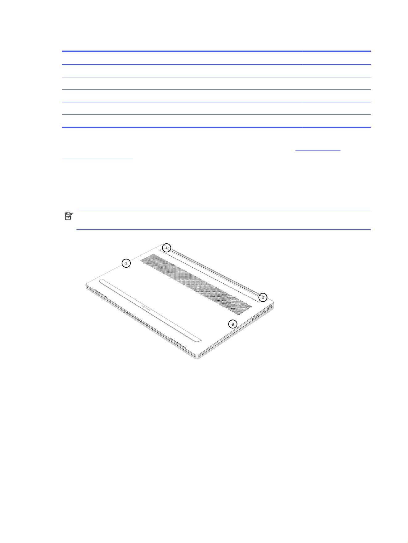
Table 5-1 Bottom cover descriptions and part numbers (continued)
Description Spare part number
Glacier silver, models with WWAN, with pen P86658-001
Atmospheric blue, models without WWAN, no pen P86659-001
Atmospheric blue, models without WWAN, with pen P86660-001
Atmospheric blue, models with WWAN, no pen P86661-001
Atmospheric blue, models with WWAN, with pen P86662-001
Before removing the bottom cover, prepare the computer for disassembly (see Preparation for
disassembly on page 37).
Remove the bottom cover:
1. Position the computer upside down.
2. Loosen the four captive Phillips screws on the bottom cover.
NOTE: The bottom cover includes a captive (not removable) screw that causes the cover to pop
up when you loosen the screw. After the cover pops up, do not continue to loosen the captive screw.
3. Insert a tool (1) into the seam near the captive screw at the top left of the bottom cover to release it.
38
Chapter 5 Removal and replacement procedures for Customer Self-Repair parts
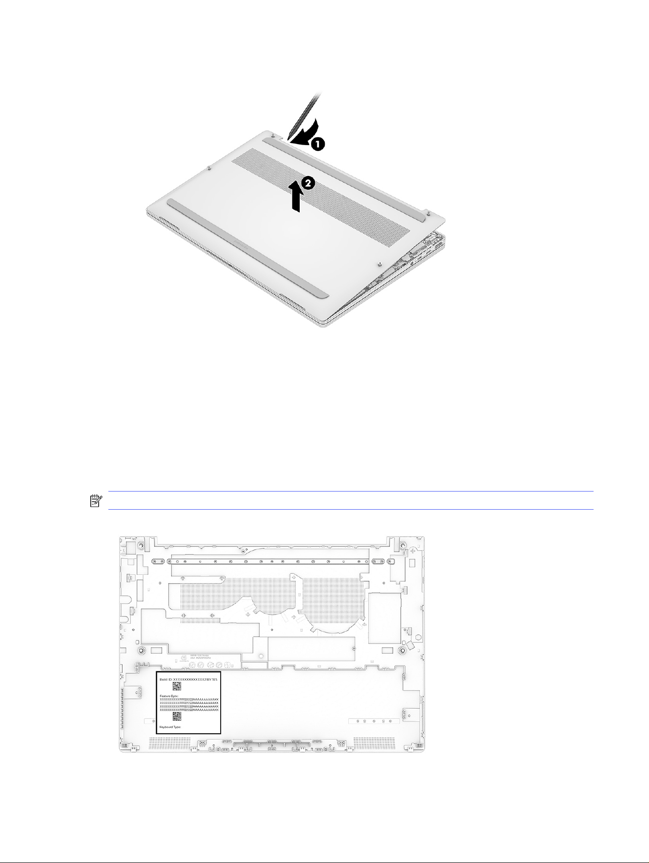
4. Lift up on the bottom cover (2) to remove it from the computer.
Reverse the removal procedures to replace the bottom cover.
When replacing the bottom cover, remove the Feature Byte label from the inside of the old bottom cover
and place it on the inside of the new bottom cover. Be sure to keep this label with the computer, because
the label is required for any future repairs.
You can locate product labels:
● Laser etched on the old bottom cover.
● In HP System Information by pressing fn + esc when you turn on the computer.
NOTE: Bottom cover appearance might vary.
Bottom cover
39
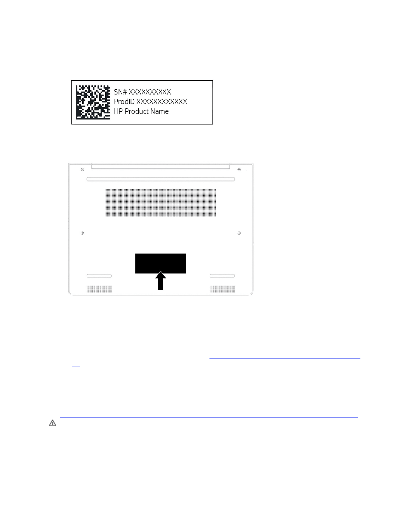
Hand write the product information onto the label of the new bottom cover. Use a ballpoint pen or marker
to avoid smudging.
Example of label information
New bottom cover label location
Battery
The battery removal procedure differs depending on whether you are removing and replacing the
existing battery or installing a new battery. You must use a revive kit to install a new battery.
● To remove and replace the existing battery, see Removing and reinstalling the same battery on page
40.
● To install a new battery, see Installing a new battery on page 42.
Removing and reinstalling the same battery
Use these procedures and illustrations to remove the battery and reinstall it.
WARNING! To avoid personal injury and damage to the product:
● Do
not
puncture, twist, or crack the battery.
● Do
not
cause an external puncture or rupture to the battery, which can cause a short inside the
battery that can result in battery thermal runaway.
40
Chapter 5 Removal and replacement procedures for Customer Self-Repair parts
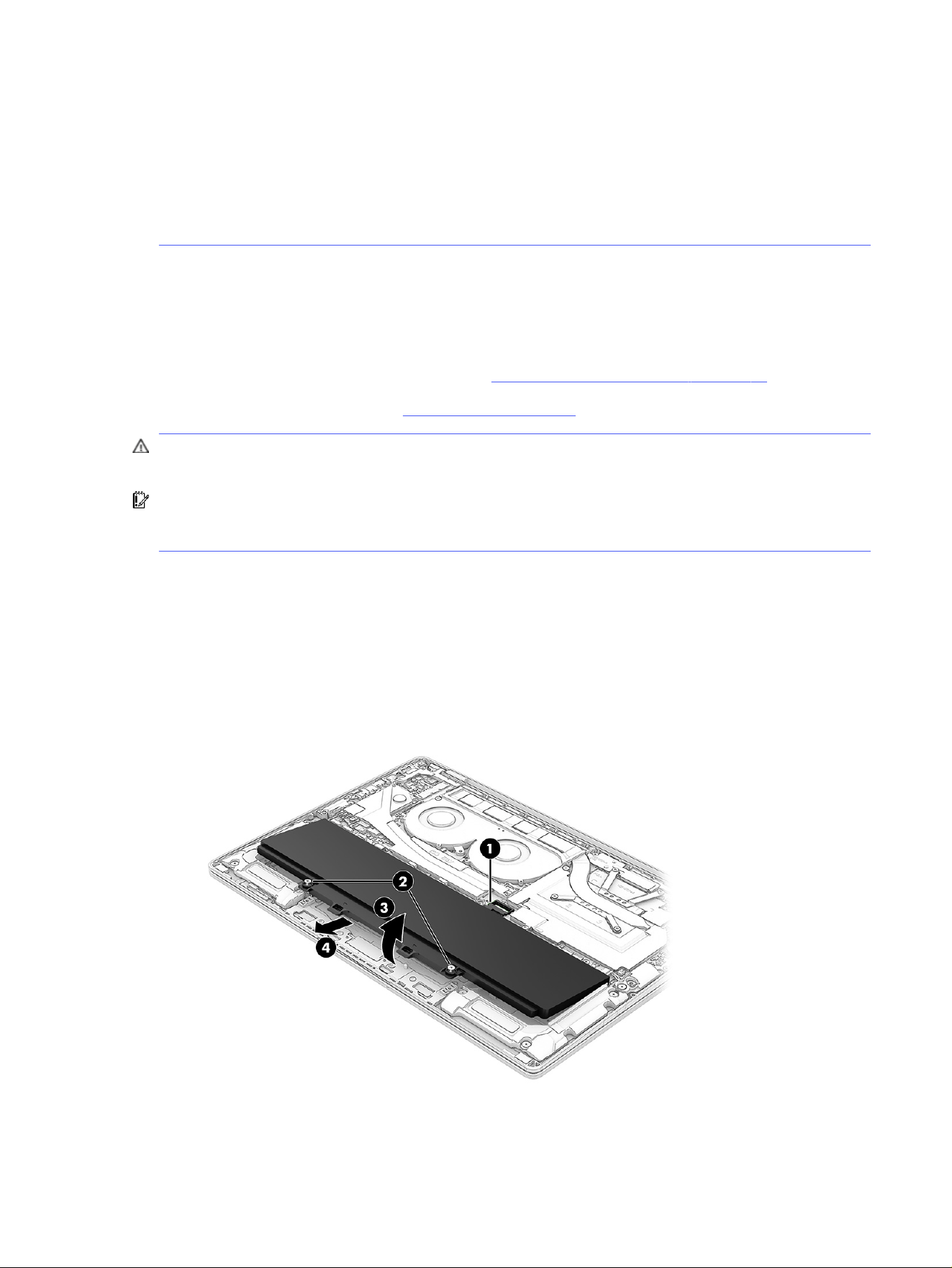
● Do
not
handle or touch the battery enclosure with sharp objects such as tweezers or pliers, which
might puncture the battery.
● Do
not
compress or squeeze the battery case with tools or heavy objects stacked on top of the
case. These actions can apply undue force on the battery.
● Do
not
touch the connectors with any metallic surface or object, such as metal tools, screws, or
coins, which can cause shorting across the connectors.
For additional battery information, see the
Regulatory, Safety, and Environmental Notices
. To access
this guide, select the Search icon in the taskbar, type HP Documentation in the search box, and then
select HP Documentation.
Before removing the battery, follow these steps:
1. Prepare the computer for disassembly (see Preparation for disassembly on page 37).
2. Remove the bottom cover (see Bottom cover on page 37).
WARNING! To reduce potential safety issues, use only the user-replaceable battery provided with the
computer, a replacement battery provided by HP, or a compatible battery purchased from HP.
IMPORTANT: Removing a battery that is the sole power source for the computer can cause loss of
information. To prevent loss of information, save your work or shut down the computer through
Windows before you remove the battery.
Remove the battery:
1. Use the tab (1) to pull the battery cable out of the system board connector.
2. Loosen the two captive Phillips screws (2) that secure the battery to the computer.
3. Lift the bottom of the battery (3) up to approximately 30°.
4. Pull the battery (4) up and away from the computer to remove it.
Removing and reinstalling the same battery
41

Reverse the removal procedures to reinstall the battery.
NOTE: When replacing the battery, be sure to completely reassemble the computer and plug in the
AC adapter before turning the computer on.
Installing a new battery
Use these procedures and illustrations to install a battery. You must use a revive kit to remove the old
battery and install a new one. The revive kit includes an empty containment tray and a containment tray
with a battery preinstalled.
Table 5-2 Battery descriptions and part numbers
Description Spare part number
Battery, 6 cell, 68 Wh (includes revive kit) P92640-001
Battery, 3 cell, 56 Wh (includes revive kit) P92639-001
Before starting this replacement procedure:
● Ensure other individuals are sufficiently clear of your workspace.
● Ensure your workspace is clear of any flammable material such as paper or oils.
● Locate the nearest ABC dry chemical fire extinguisher for use in an emergency.
WARNING! This procedure requires removing the battery or disconnecting the battery cable. Use
care to avoid bending, twisting, or puncturing the battery regardless of its condition. Failure to follow
this replacement guide or to use HP recommended tools might damage the system and/or cause a
safety hazard.
● Do
not
remove the battery from the containment tray.
● Do
not
handle or touch the battery enclosure with sharp objects such as tweezers or pliers, which
might puncture the battery.
● Do
not
touch the connectors with any metallic surface or object, such as metal tools, screws, or
coins, which can cause shorting across the connectors.
Should a part become stuck or difficult to remove when opening a unit where a swollen battery is
suspected, or if the battery becomes stuck in the unit, stop, and contact HP Support for assistance. Do
not try to remove a battery by force.
NOTE: Screw locations, latch locations, and internal components might vary.
Before removing the battery, follow these steps:
1. Prepare the computer for disassembly (see Preparation for disassembly on page 37).
42
Chapter 5 Removal and replacement procedures for Customer Self-Repair parts
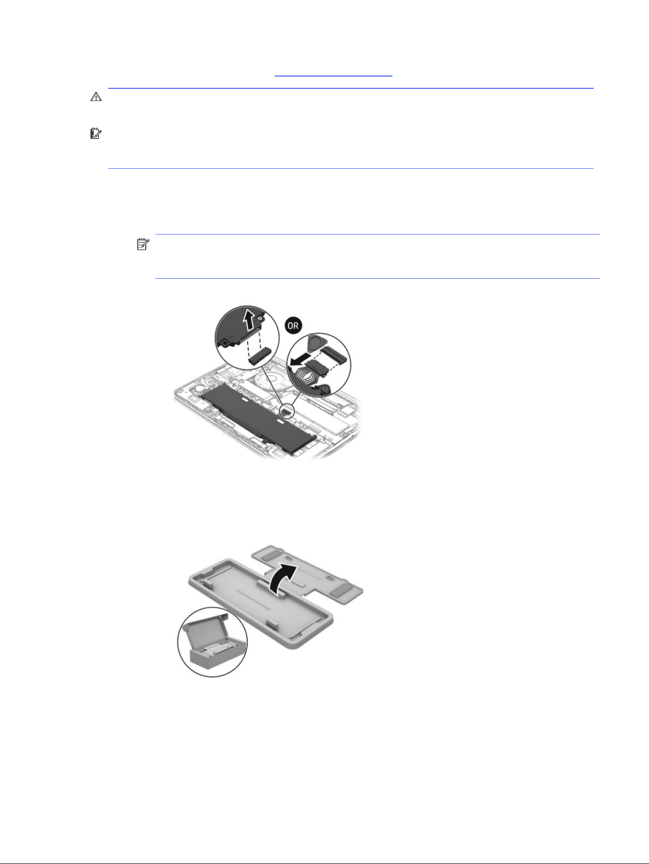
2. Remove the bottom cover (see Bottom cover on page 37).
WARNING! To reduce potential safety issues, use only the user-replaceable battery provided with the
computer, a replacement battery provided by HP, or a compatible battery purchased from HP.
IMPORTANT: Removing a battery that is the sole power source for the computer can cause loss of
information. To prevent loss of information, save your work or shut down the computer through
Windows before you remove the battery.
1. Remove the battery using the revive kit:
a. Disconnect the battery cable from the system board. The connector location might vary.
NOTE: You can disconnect the cable from the battery. The battery spare part kit does not
come with the battery cable, so be sure to use the old battery cable or order a new battery
cable when replacing the battery.
b. Open the empty battery containment tray.
Installing a new battery
43
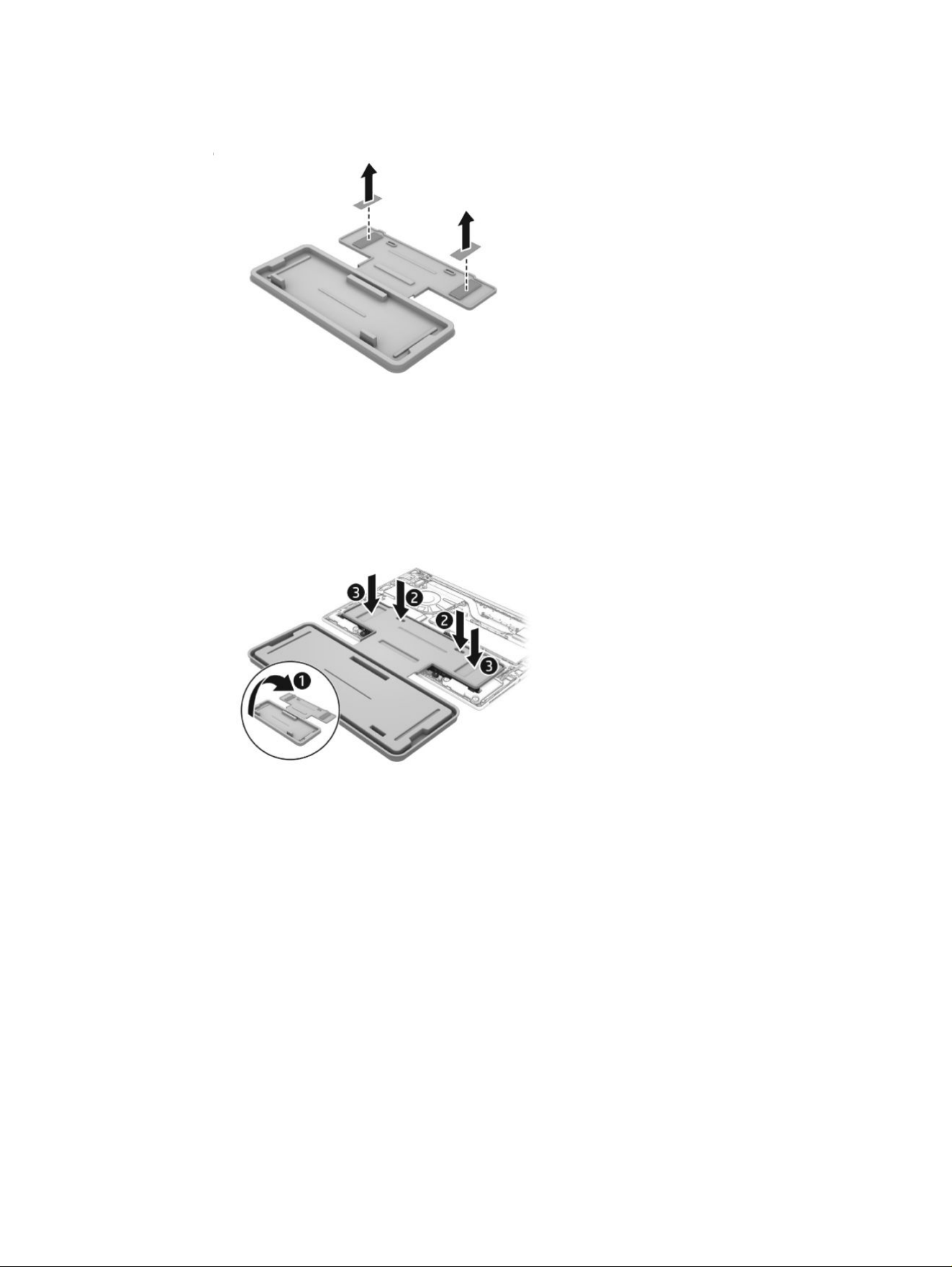
c. Remove the paper backing layer from the adhesive on the tray.
d. Turn the tray (1) over so that the adhesive is facing down.
e. Place the tray (2) centered on the battery.
f. Press down on the indentations on the tray (3) to adhere it to the battery.
g. Remove the Phillips screws (1) that secure the battery to the computer. Number of screws and
screw locations might vary.
44
Chapter 5 Removal and replacement procedures for Customer Self-Repair parts
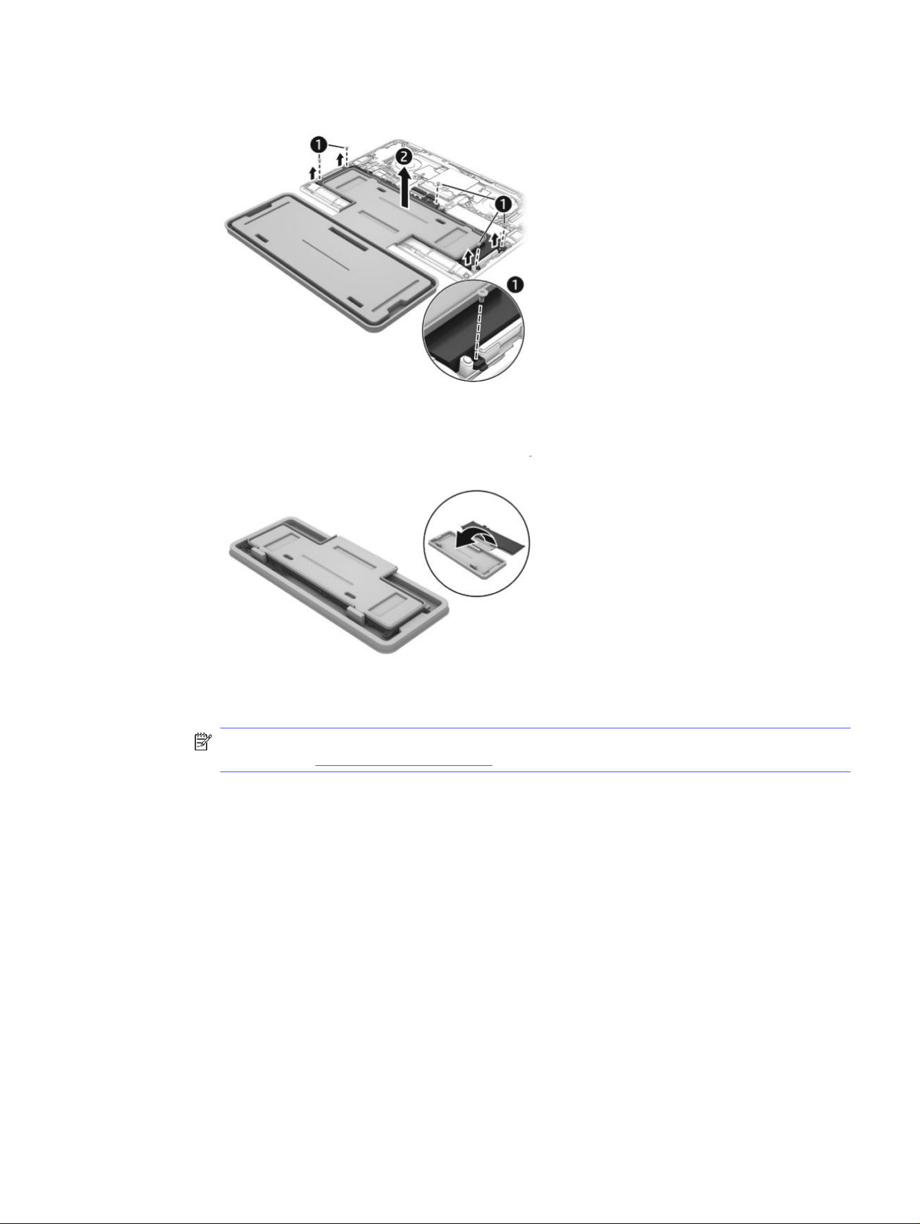
h. Lift the top of the tray (2) to remove the battery from the computer.
i. Rotate the battery up and over into the cavity of the containment tray.
NOTE: Please recycle responsibly. For more information about recycling programs, see the
HP website at http://www.hp.com/recycle.
2. Install the battery using the revive kit:
a. Open the containment tray that includes the new battery.
Installing a new battery
45
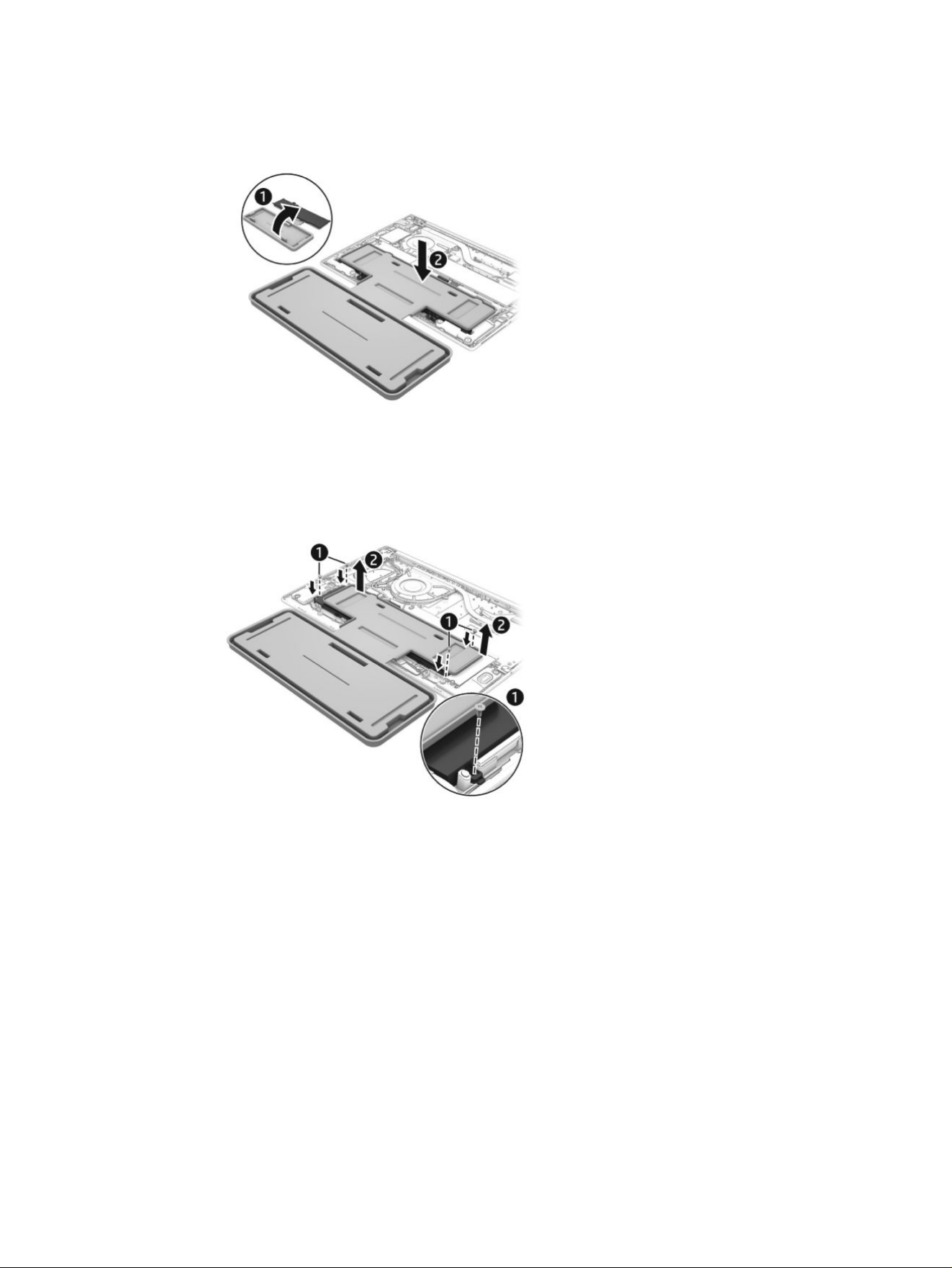
b. Turn the tray (1) over so the battery is facing downward, and then insert the battery (2) into the
computer. Adhesive secures the battery to the tray.
c. Install the Phillips screws (1) to secure the battery. Number of screws and screw locations
might vary.
d. Lift the containment tray (2) off the battery.
46
Chapter 5 Removal and replacement procedures for Customer Self-Repair parts
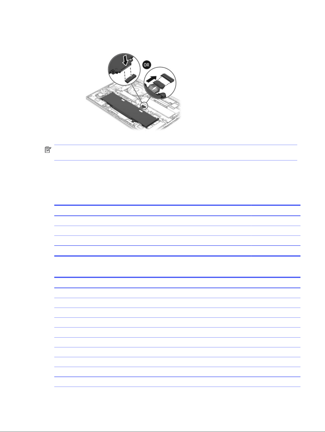
e. Connect the battery cable to the system board. The connector location might vary.
NOTE: When replacing the battery, be sure to completely reassemble the computer and plug in the
AC adapter before turning the computer on.
Keyboard
Use this procedure and illustration to remove the keyboard. The first table includes the keyboard spare
part numbers. The second table includes keyboard country codes.
Table 5-3
Keyboard descriptions and part numbers
Description Spare part number
Atmospheric blue P86838-xx1
Atmospheric blue, privacy P86839-xx1
Glacier silver P86840-xx1
Glacier silver, privacy P86841-xx1
Table 5-4 Spare part country codes
For use in country or region Spare part number
Belgium -A41
Czech Republic/Slovakia -FL1
Denmark, Finland, and Norway -DH1
French Canada -DB1
France -051
Germany -041
Greece -151
Israel -BB1
Italy -061
Japan -291
Keyboard 47

Table 5-4 Spare part country codes (continued)
For use in country or region Spare part number
Latin America -161
The Netherlands -B31
Russia -251
Saudi Arabia -171
Slovenia -BA1
South Korea -AD1
Spain -071
Switzerland -BG1
Taiwan -AB1
Thailand -281
Turkey -141
Ukraine -BD1
United Kingdom -031
United States -001
Before removing the keyboard, follow these steps:
■
Prepare the computer for disassembly (see Preparation for disassembly on page 37).
Disable the battery using Computer Setup (BIOS)
Before replacing the keyboard, be sure to disable the battery as follows:
CAUTION: Failure to disable the battery before removing the keyboard can result in component
damage.
1. Turn off the computer.
2. Disconnect the power and all external devices.
3. Ground yourself to prevent electrostatic discharge (ESD) (use a wrist strap or touch bare metal).
4. Disable the battery in Computer Setup:
a. Press the power button.
b. Press F10 repeatedly to enter Computer Setup.
i. If F10 is not functional, repeatedly press Esc to access the Startup menu, and then select
BIOS Setup (F10).
ii. If the keyboard is not functional, follow steps to enter Computer Setup from the operating
system at https://www.youtube.com/shorts/GdFCKLlPM3o.
c. From the main setup menu, select Prepare System for Hardware Change. If this option is not
available, Tamper Lock is enabled. Disable Tamper Lock to proceed.
48
Chapter 5 Removal and replacement procedures for Customer Self-Repair parts
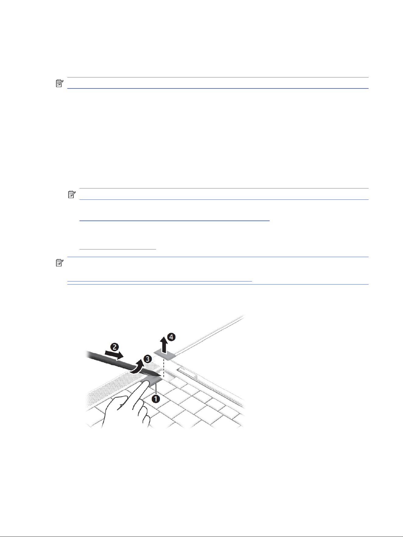
d. Select Confirm to continue.
5. Select Esc to exit, and then select Yes to save changes. The computer shuts down and the battery is
disabled.
NOTE: You must connect a power adapter to restart the computer.
Change the keyboard language (if applicable)
To change the keyboard language, use the following steps:
1. Follow step 4b from the previous section to enter Computer Setup.
2. From the main menu, select Advanced.
3. Select Keyboard Part Number Suffix After Replacement.
4. Check the last 3-4 letters on the part box label for the new keyboard. If the letters match any of the
four following codes, select the matching code: JPN2, KOR, BRZL, GR.
NOTE: If there is no match, select Others.
5. To change keyboard layout and operating system language, follow the steps at:
https://support.hp.com/us-en/document/ish_9596154-9596198-16
- or -
Changing keyboard layout
NOTE: After installation, go to Diagnostics and select Component tests to confirm that the keyboard
in functioning correctly. For more information, see
https://support.hp.com/us-en/help/hp-pc-hardware-diagnostics.
1. While pressing down on the key (1) next to the Esc key, insert a tool (2) under the Esc key, and then
twist the tool (3) to remove the Esc key (4) from the keyboard.
2. Insert a tool (1) under the tab on the left side of the Esc key cavity, and then push the tool (2) down to
lift up the top of the keyboard.
Keyboard
49
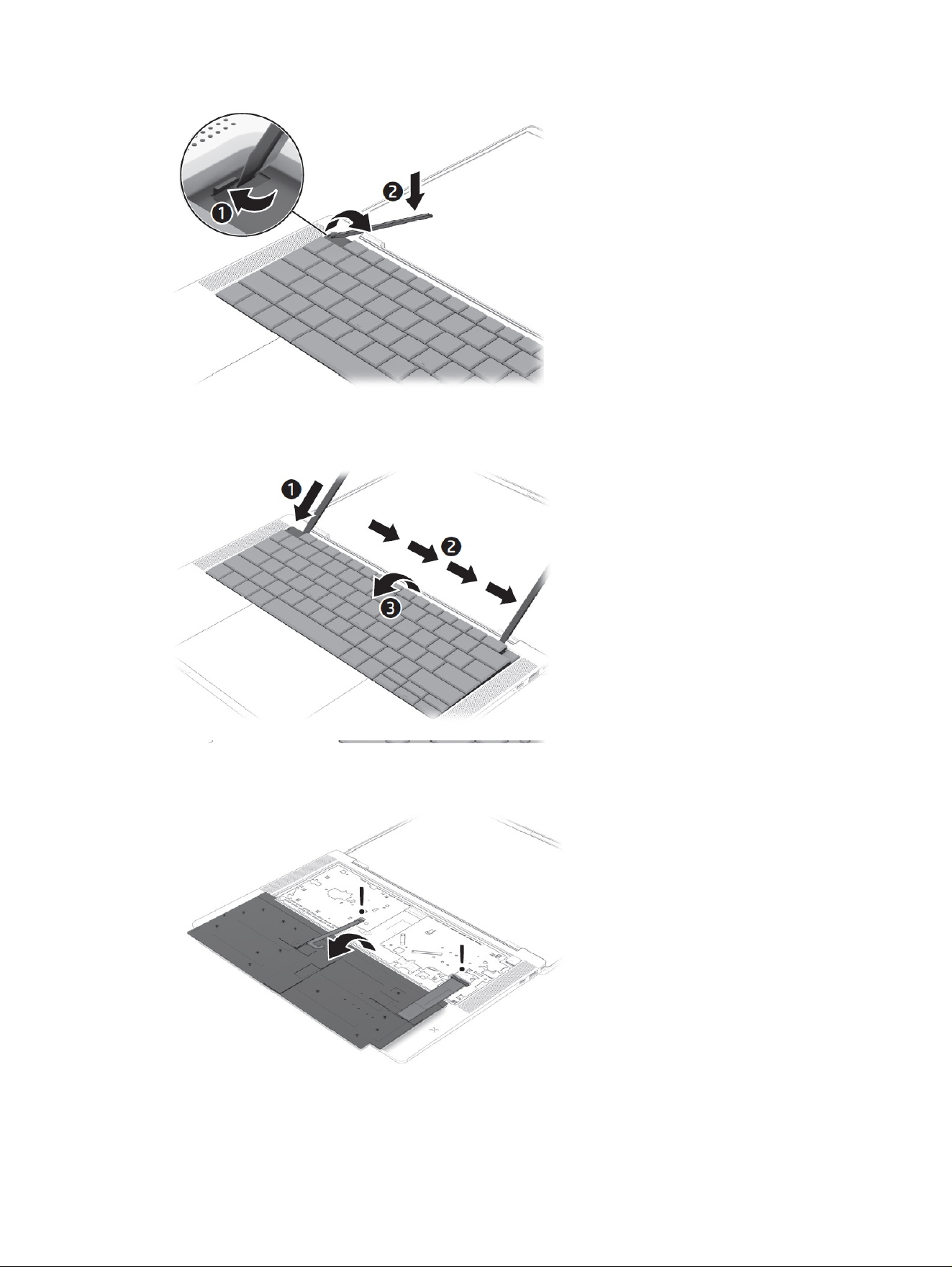
3. Insert a tool (1) under the top left of the lifted keyboard, and then pull the tool (2) to the right to release
the top of the keyboard. Lift the top of the keyboard (3) up and over onto the touchpad.
When lifting the keyboard over onto the touchpad, be sure not to accidentally disconnect the two
cables from the connectors on the system board.
50
Chapter 5 Removal and replacement procedures for Customer Self-Repair parts
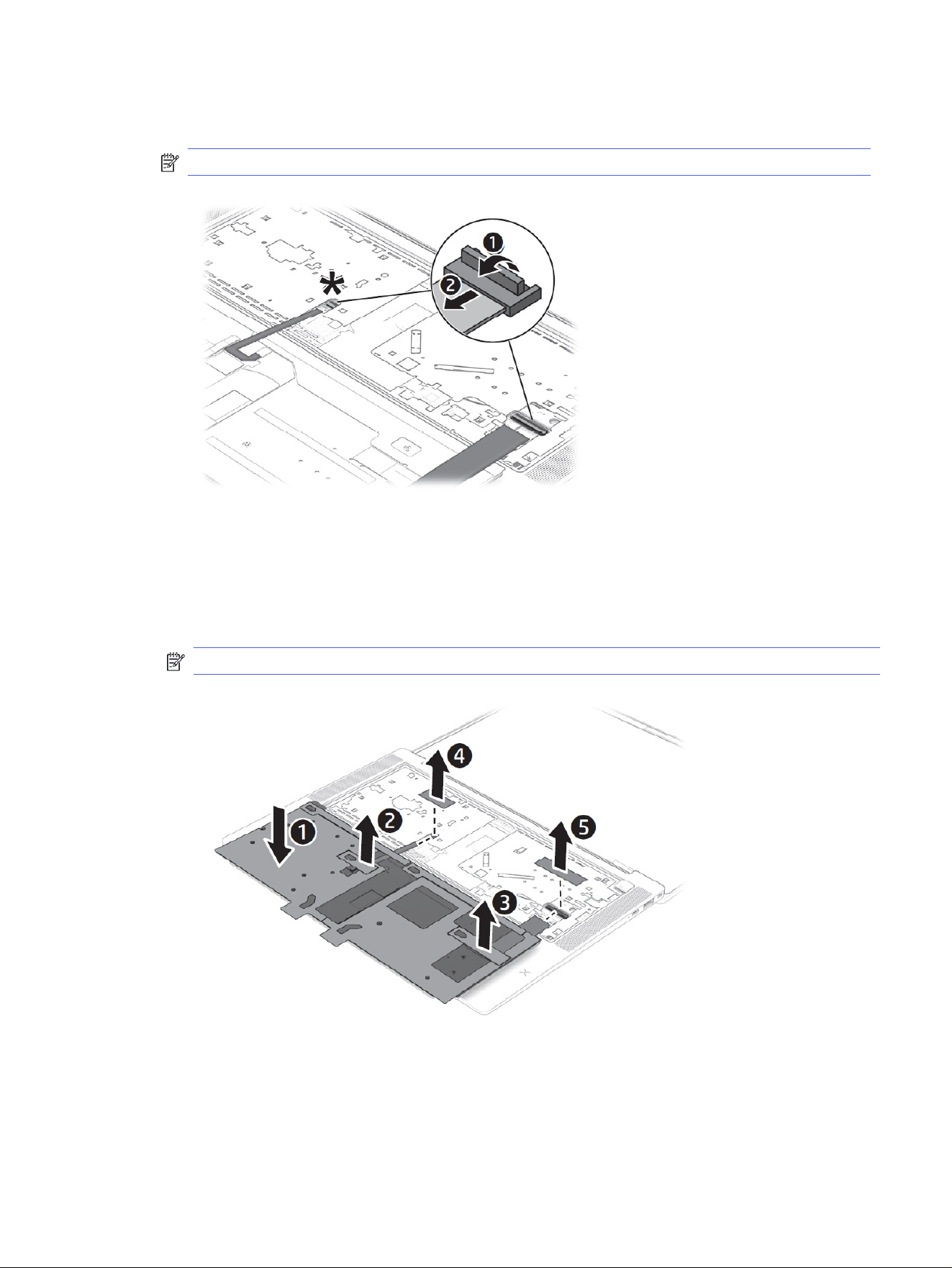
4. Disconnect the two cables from the ZIF connectors on the computer by lifting the latch (1) on the
connector, and then pulling the cable (2) out of the connector. Remove the keyboard
NOTE: *The left backlight cable is available only on select products.
Install the new keyboard:
1. Place the new keyboard (1) onto the computer.
2. Remove the covers (2) (3) from the bottom of the keyboard.
3. Remove the covers (4) (5) from the cable connectors on the keyboard.
NOTE: The backlight cable (4) is available only on select products.
Keyboard
51
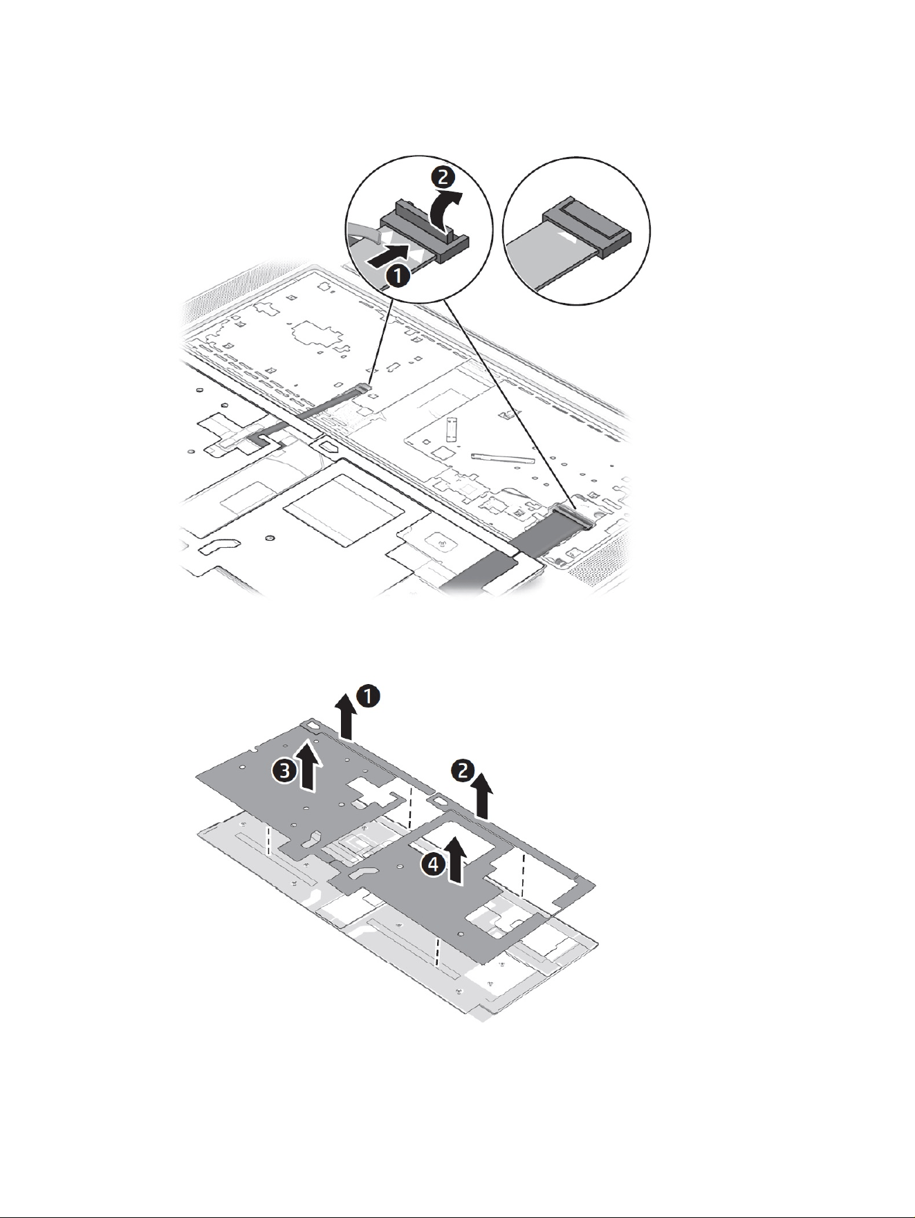
4. Insert the keyboard cables (1) into the connectors on the system board, and then close the latch (2)
on the connectors.
5. Remove the liner from the bottom of the keyboard in the order shown in the following illustration.
52
Chapter 5 Removal and replacement procedures for Customer Self-Repair parts
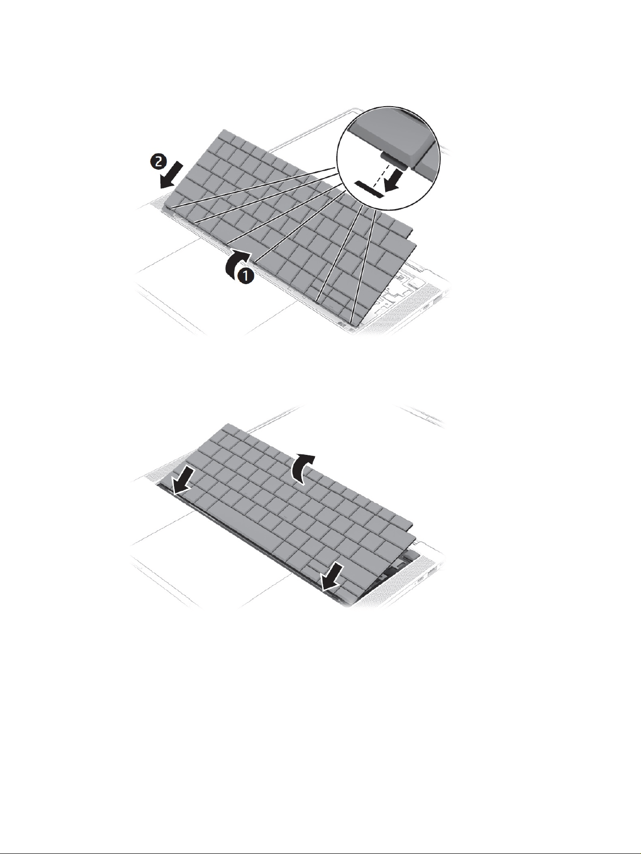
6. Insert the tabs (1) on the bottom of the keyboard into slots in the computer, and then push the
keyboard (2) firmly down into the computer.
7. With the bottom of the keyboard inserted into the computer, rotate the top of the keyboard down
into place.
Keyboard
53
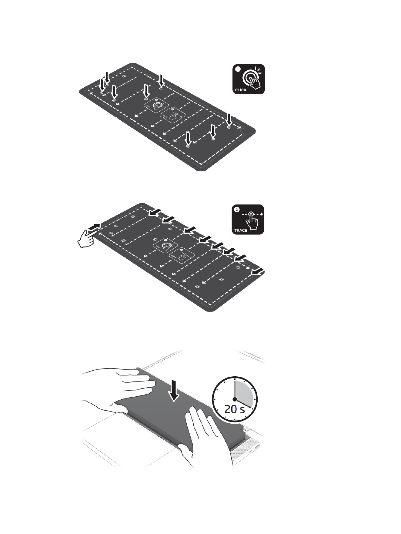
8. Press down on the circles on the keyboard to engage the mechanical hooks to the computer.
9. Press along the directions of the arrows on the keyboard to adhere it to the computer.
10. Use the block included in the kit to press down firmly and evenly on the keyboard for 20 seconds.
54
Chapter 5 Removal and replacement procedures for Customer Self-Repair parts
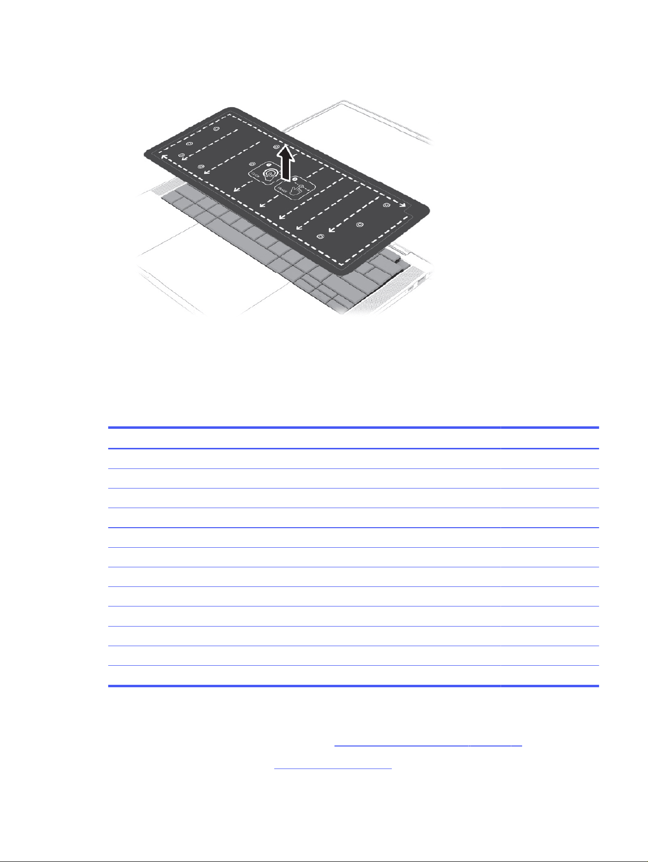
11. Remove the cover from the keyboard.
Reverse this procedure to install the keyboard.
Solid-state drive
Use this procedure and illustration to remove the SSD.
Table 5-5
SSD descriptions and part numbers
Description Spare part number
2 TB, PCIe-5 × 4, nM P41682-001
2 TB, PCIe-5 × 4, value P73031-001
2 TB, PCIe-5 × 4, SED P90258-001
1 TB, PCIe-4 × 4, value N77394-001
1 TB, PCIe-5 × 4, nM P32587-001
1 TB, PCIe-5 × 4 P73030-001
1 TB, PCIe-5 × 4, SED P90257-001
512 GB, PCIe-4 × 4, value N44321-001
512 GB, PCIe-5 × 4 P73029-001
512 GB, PCIe-5 × 4, SED P86946-001
SSD shielding kit P93176-001
SSD heat sink P87602-001
Before removing the SSD, follow these steps:
1. Prepare the computer for disassembly (see Preparation for disassembly on page 37).
2. Remove the bottom cover (see Bottom cover on page 37).
Solid-state drive
55
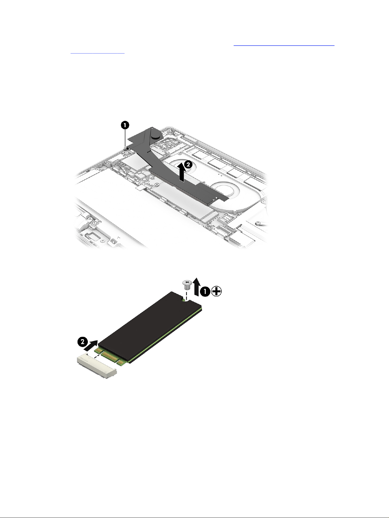
3. Disconnect the battery cable from the system board (see Removing and reinstalling the same
battery on page 40).
Remove the SSD:
1. Loosen the captive Phillips screw (1) that secures the SSD/WWAN module heat sink.
2. Remove the heat sink (2) from the computer.
3. Remove the Phillips P2.0× 3.0 screw (1), and then pull the SSD (2) out of the socket.
Reverse the removal procedures to install an SSD.
When installing an SSD, be sure a thermal pad is installed under of the SSD.
56
Chapter 5 Removal and replacement procedures for Customer Self-Repair parts
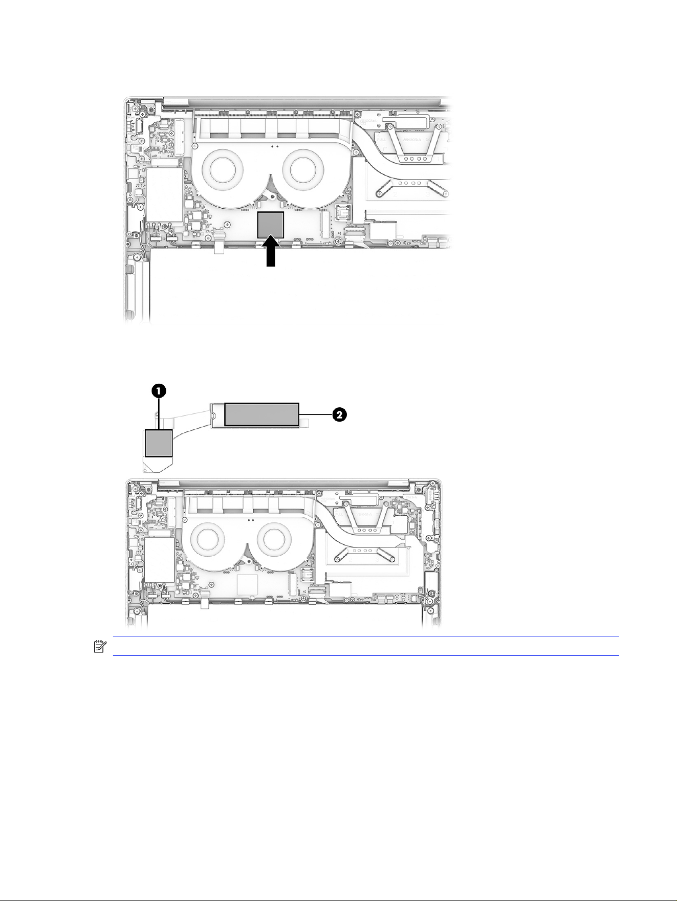
When installing the SSD/WWAN heat sink, be sure a thermal pad is installed on the bottom of the heat
sink where it covers the WWAN module (1) and the SSD (2).
NOTE: SSDs are designed with a notch to prevent incorrect insertion.
Solid-state drive
57

Removal and replacement procedures for
authorized service provider parts
6
This chapter provides removal and replacement procedures for authorized service provider parts.
IMPORTANT: Only an authorized service provider should access the components described in this
chapter. Accessing these parts can damage the computer or void the warranty.
NOTE: Details about your computer, including model, serial number, product key, and length of
warranty, are on the service tag at the bottom of your computer.
NOTE: The HP Support YouTube Channel (in English) has videos that provide step-by-step removal
and replacement instructions for many common parts and models.
Component replacement procedures
Use the procedures described in this section to remove and replace computer components.
NOTE: HP continually improves and changes product parts. For complete and current information
about supported parts for your computer, go to https://partsurfer.hp.com/, select your country or
region, and then follow the on-screen instructions.
Make special note of each screw size and location during removal and replacement.
WWAN module
Use this procedure and illustration to remove the WWAN module.
Table 6-1
WWAN module descriptions and part numbers
Description Spare part number
HP R15 5G Solution P06930-001
HP R15 5G Solution with HP Go P26028-001
HP RW220-GL LTE (CAT-1bis) (low power) P47161-001
HP R18 5G Solution P62206-001
HP R18 5G Solution with HP Go P62207-001
IMPORTANT: To prevent an unresponsive system, replace the wireless module only with a wireless
module authorized for use in the computer by the governmental agency that regulates wireless
devices in your country or region. If you replace the module and then receive a warning message,
remove the module to restore device functionality, and then contact technical support.
Before removing the WWAN module, follow these steps:
1. Prepare the computer for disassembly (Preparation for disassembly on page 37).
58
Chapter 6 Removal and replacement procedures for authorized service provider parts
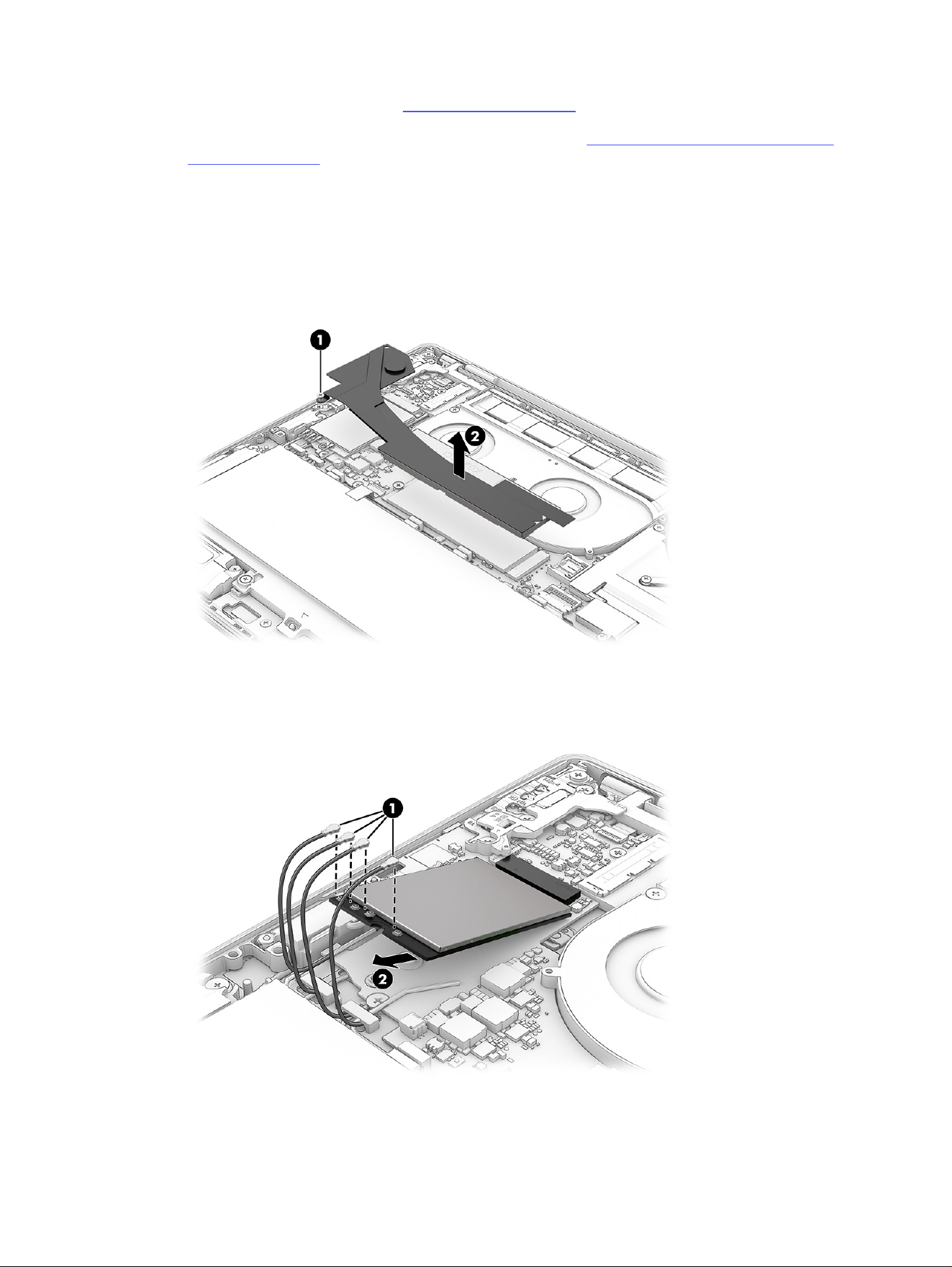
2. Remove the bottom cover (see Bottom cover on page 37).
3. Disconnect the battery cable from the system board (see Removing and reinstalling the same
battery on page 40).
Remove the WWAN module:
1. Loosen the captive Phillips screw (1) that secures the SSD/WWAN module heat sink.
2. Remove the heat sink (2) from the computer.
3. Disconnect the antenna cables (1) from the module terminals.
4. Remove the module (2) by pulling it away from the slot at an angle.
WWAN module
59
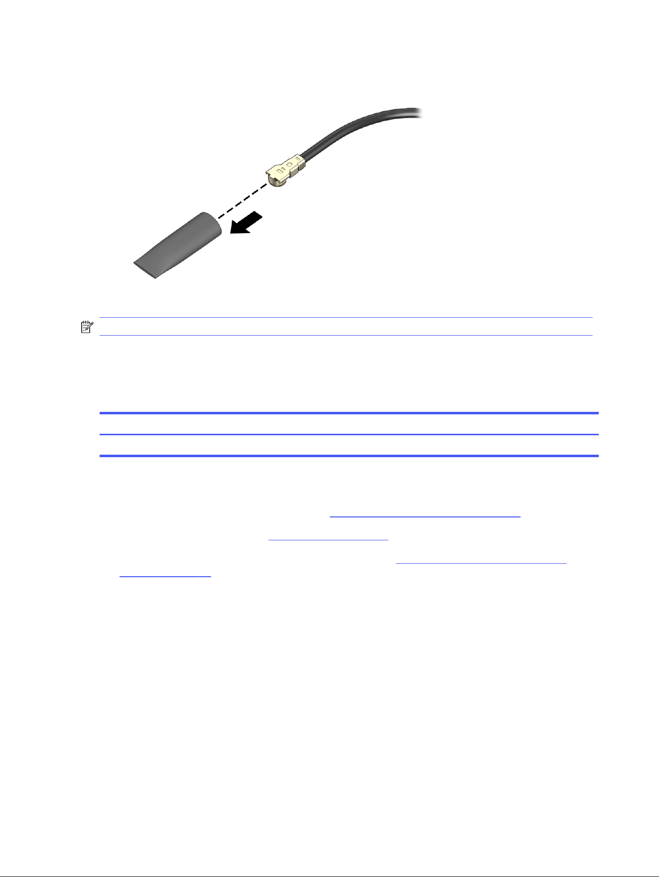
5. If the WWAN antenna is not connected to the terminal on the WWAN module, install a protective
sleeve on the antenna connector, as shown in the following illustration.
Reverse this procedure to install the WWAN module.
NOTE: WWAN modules are notched to prevent incorrect installation.
Speakers
Use this procedure and illustration to remove the speakers.
Table 6-2
Speaker descriptions and part numbers
Description Spare part number
Speakers P86637-001
Before removing the speakers, follow these steps:
1. Prepare the computer for disassembly (see Preparation for disassembly on page 37).
2. Remove the bottom cover (see Bottom cover on page 37).
3. Disconnect the battery cable from the system board (see Removing and reinstalling the same
battery on page 40).
Remove the speakers:
1. Disconnect the speaker cables (1) from the system board.
2. Remove the eight Phillips M2.0 × 2.0 screws (2) that secure the speakers.
60
Chapter 6 Removal and replacement procedures for authorized service provider parts
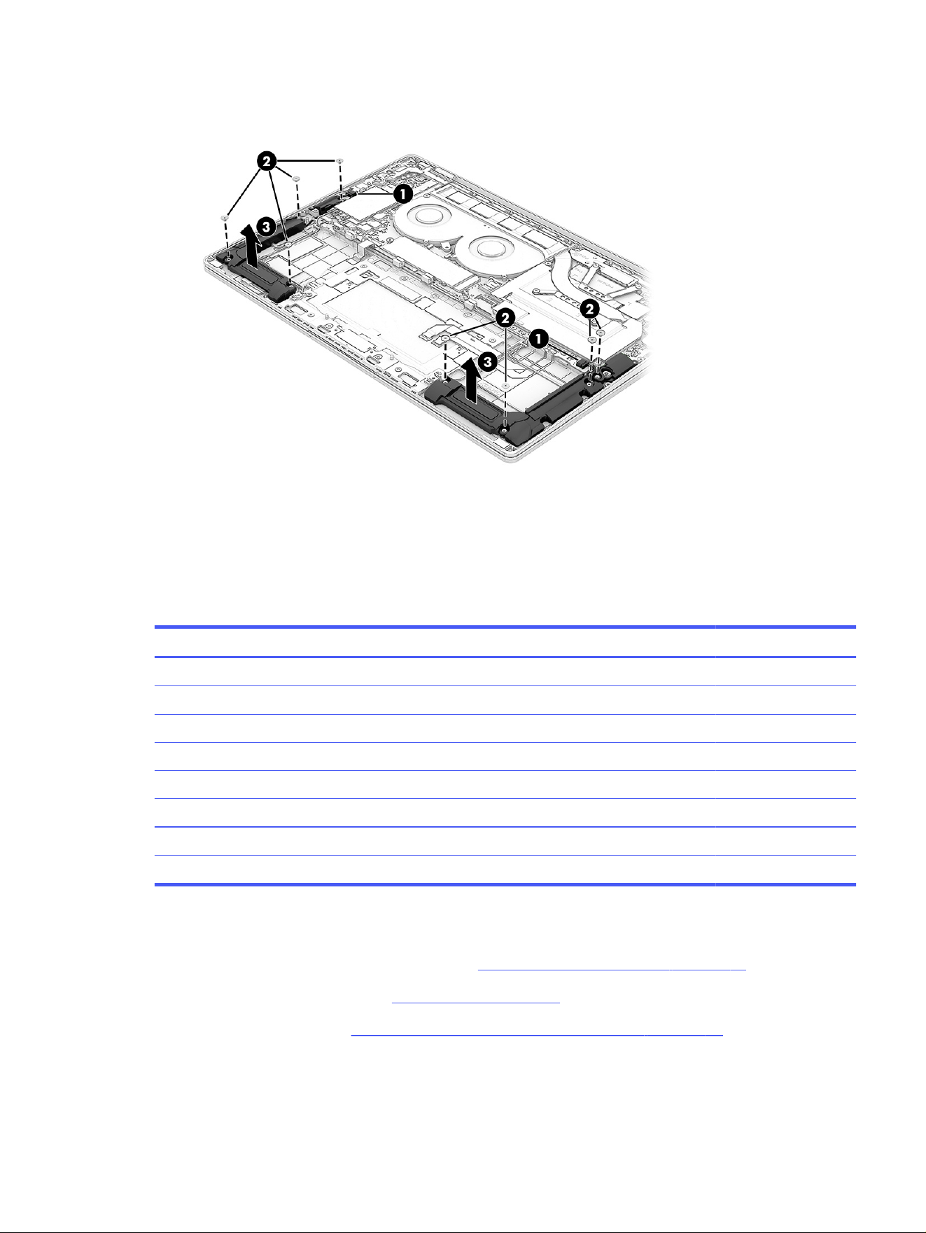
3. Remove the speakers (3) from the computer. The speakers are also secured with adhesive.
Reverse this procedure to install the speakers.
Touchpad
Use this procedure and illustration to remove the touchpad.
Table 6-3
Touchpad descriptions and part numbers
Description Spare part number
Click, glacier silver P87574-001
Click, glacier silver, with NFC P87575-001
Click, atmospheric blue P87576-001
Click, atmospheric blue, with NFC P87577-001
Haptic, glacier silver P87580-001
Haptic, glacier silver, with NFC P87581-001
Haptic, atmospheric blue P87582-001
Haptic, atmospheric blue, with NFC P87583-001
Before removing the touchpad, follow these steps:
1. Prepare the computer for disassembly (see Preparation for disassembly on page 37).
2. Remove the bottom cover (see Bottom cover on page 37).
3. Remove the battery (see Removing and reinstalling the same battery on page 40).
Remove the touchpad from models with an NFC module:
1. Disconnect the cable from the ZIF connector (1) on the NFC module.
Touchpad
61
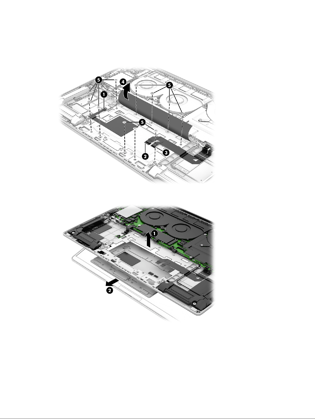
2. Disconnect the cables from the ZIF connectors (2) (3) on the touchpad.
3. Lift the protective shielding (4) up from the top of the touchpad.
4. Remove the 11 Phillips M1.2 × 1.0 screws (5) from the touchpad.
5. Lift the top cover (1) up off the touchpad, and then remove the touchpad (2) from under the top cover.
Remove the touchpad from models without an NFC module:
1. Disconnect the cables from the ZIF connectors (1) (2) on the touchpad.
62
Chapter 6 Removal and replacement procedures for authorized service provider parts
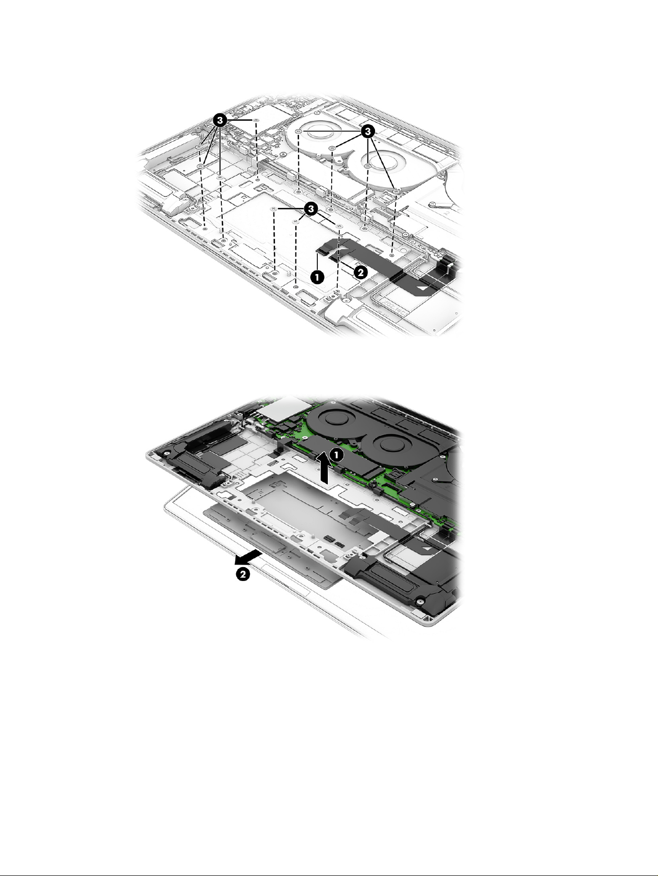
2. Remove the 11 Phillips M1.2 × 1.0 screws (3) from the touchpad.
3. Lift the top cover (1) up off the touchpad, and then remove the touchpad (2) from under the top
cover.
4. (NFC models) Disconnect the NFC cable (1) from the system board ZIF connector.
5. Disconnect the touchpad cable (2) from the system board ZIF connector.
Touchpad
63
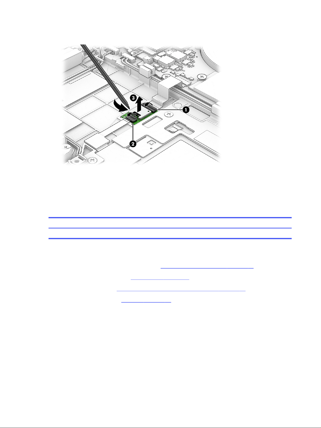
6. Use a tool to release the NFC module (3) from the computer.
Reverse the removal procedures to install the touchpad.
WWAN antennas
Use this procedure and illustration to remove the WWAN antennas.
Table 6-4
WWAN antennas description and part number
Description Spare part number
WWAN antennas (left and right) P86665-001
Before removing the WWAN antennas, follow these steps:
1. Prepare the computer for disassembly (see Preparation for disassembly on page 37).
2. Remove the bottom cover (see Bottom cover on page 37).
3. Remove the battery (see Removing and reinstalling the same battery on page 40).
4. Remove the speakers (see Speakers on page 60).
Remove the left WWAN antenna:
1. Disconnect the antenna cables (1) from the WWAN module.
2. Remove the blue tape (2) from the cables under the left speaker.
3. Remove the black tape (3) from the cables under the left speaker.
4. Remove the left two cables (4) from the routing channels below the WWAN module and routing
under the left speaker.
5. Peel the left antenna (5) off the computer.
64
Chapter 6 Removal and replacement procedures for authorized service provider parts
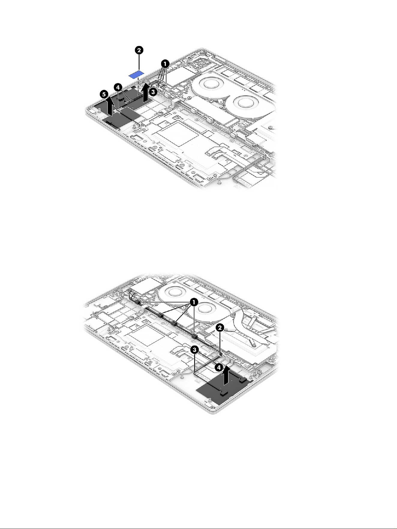
Remove the right WWAN antenna:
1. Remove the right two antenna cables from the four black rubber clips (1) under the system board.
2. Remove the right two antenna cables from the gray plastic clip (2) under the system board.
3. Remove the left two cables from the routing channels (3) near the right speaker.
4. Peel the right antenna (4) off the computer.
Reverse this procedure to install the WWAN antennas.
Fan/heat sink assembly
Use this procedure and illustration to remove the fan/heat sink assembly.
Fan/heat sink assembly
65
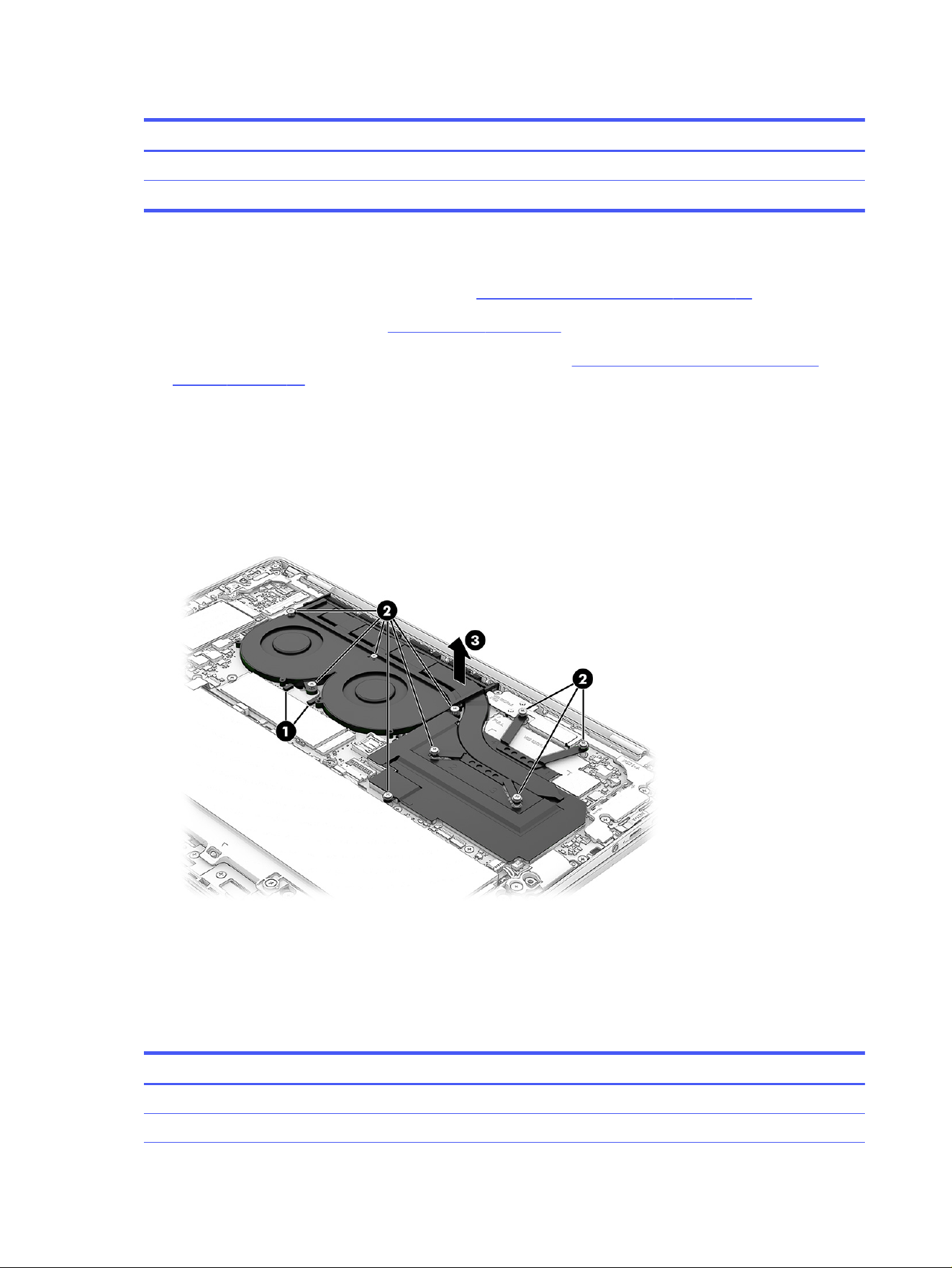
Table 6-5 Fan/heat sink assembly descriptions and part numbers
Description Spare part number
Fan/heat sink assembly P86638-001
Thermal pad Q02317-001
Before removing the fan/heat sink assembly, follow these steps:
1. Prepare the computer for disassembly (see Preparation for disassembly on page 37).
2. Remove the bottom cover (see Bottom cover on page 37).
3. Disconnect the battery cable from the system board (see Removing and reinstalling the same
battery on page 40).
Remove the fan/heat sink assembly:
1. Disconnect the two fan cables (1) from the system board.
2. Loosen the nine captive Phillips screws (2) from the assembly.
3. Lift the assembly (3) out of the computer.
Reverse this procedure to install the fan/heat sink assembly.
System board
Use these procedures and illustrations to remove the system board.
Table 6-6
System board descriptions and part numbers
Description Spare part number
System board (includes processor and system memory)
Intel Core Ultra X7 368H processor and 32 GB system memory (Operating System Recovery [OSR]) P86390-601
66 Chapter 6 Removal and replacement procedures for authorized service provider parts

Table 6-6 System board descriptions and part numbers (continued)
Description Spare part number
Intel Core Ultra X7 358H processor and 64 GB system memory P86386-601
Intel Core Ultra X7 358H processor and 64 GB system memory (PRC) P86389-601
Intel Core Ultra X7 358H processor and 32 GB system memory P86385-601
Intel Core Ultra X7 358H processor and 32 GB system memory (PRC) P86388-601
Intel Core Ultra 7 366H processor and 64 GB system memory P86387-601
Intel Core Ultra 7 366H processor and 32 GB system memory P86375-601
Intel Core Ultra 7 366H processor and 32 GB system memory (PRC) P86376-601
Intel Core Ultra 7 366H processor and 32 GB system memory (OSR) P86374-601
Intel Core Ultra 7 366H processor and 24 GB system memory P86373-601
Intel Core Ultra 7 356H processor and 32 GB system memory P86371-601
Intel Core Ultra 7 356H processor and 32 GB system memory (PRC) P86372-601
Intel Core Ultra 7 356H processor and 24 GB system memory P86384-601
Intel Core Ultra 5 338H processor and 32 GB system memory (OSR) P86382-601
Intel Core Ultra 5 338H processor and 32 GB system memory (PRC) P86383-601
Intel Core Ultra 5 335 and 32 GB system memory P86380-601
Intel Core Ultra 5 335 and 32 GB system memory (OSR) P86379-601
Intel Core Ultra 5 335 and 32 GB system memory (PRC) P86381-601
Intel Core Ultra 5 335 and 24 GB system memory P86370-601
Intel Core Ultra 5 335 and 16 GB system memory P86369-601
Intel Core Ultra 5 325 and 32 GB system memory P86378-601
Intel Core Ultra 5 325 and 24 GB system memory P86368-601
Intel Core Ultra 5 325 and 24 GB system memory (PRC) P86377-601
Intel Core Ultra 5 325 and 16 GB system memory P86367-601
Before removing the system board, follow these steps:
1. Prepare the computer for disassembly (see Preparation for disassembly on page 37).
2. Remove the bottom cover (see Bottom cover on page 37).
3. Disconnect the battery cable from the system board (see Removing and reinstalling the same
battery on page 40).
4. Remove the SSD/WWAN heat sink and SSD (see Solid-state drive on page 55).
5. Remove the WWAN module (see WWAN module on page 58).
6. Remove the fan/heat sink assembly (see Fan/heat sink assembly on page 65).
Remove the system board:
System board
67
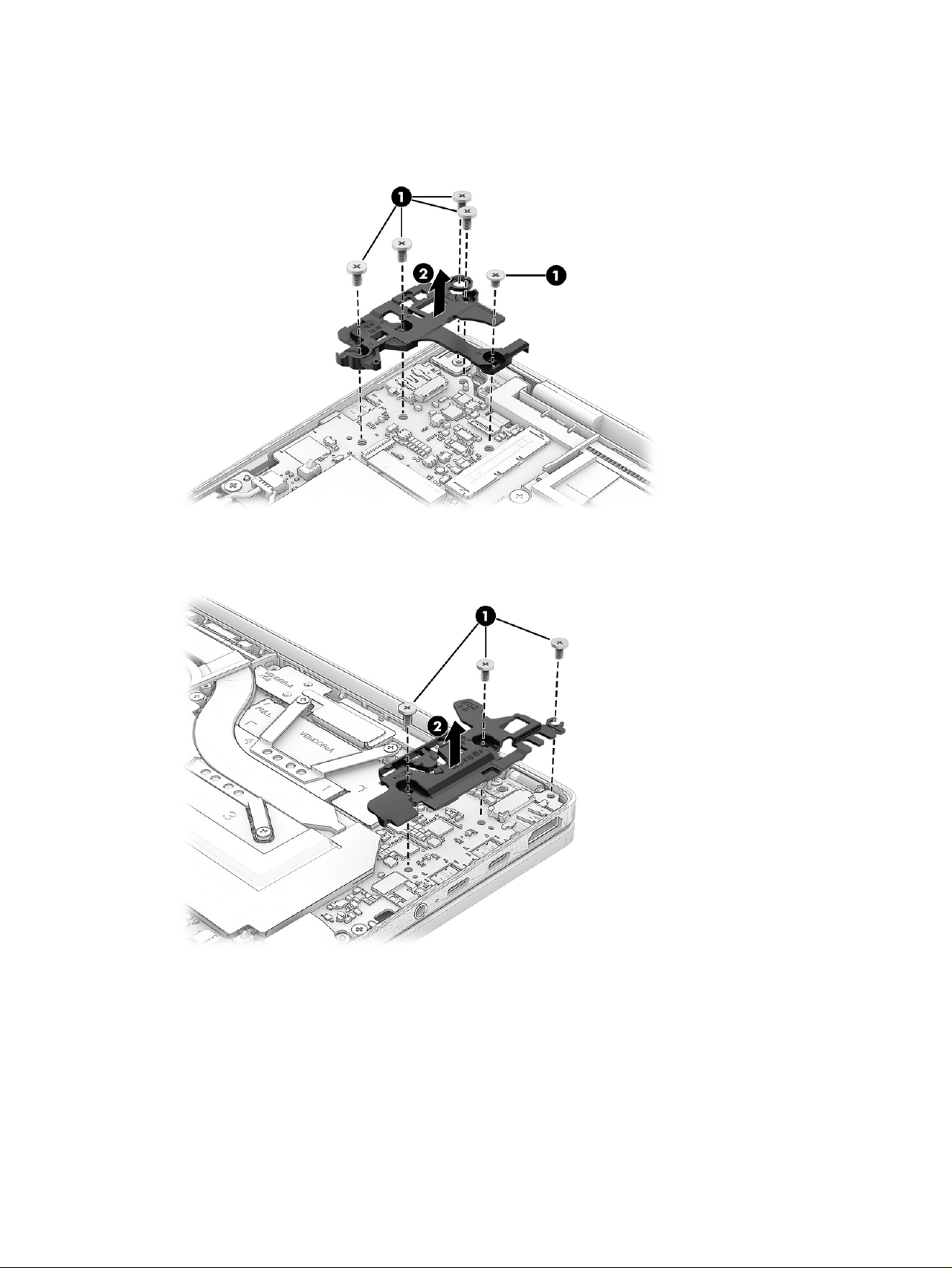
1. Remove the five Phillips M2.0 × 4.0 screws (1) from the left bracket, and then lift the bracket (2) off
the system board.
2. Remove the three Phillips M2.0 × 4.0 screws (1) from the right bracket, and then lift the bracket (2) off
the system board.
3. Disconnect the following cables from the system board:
● Power button cable (ZIF) (1)
● Camera cable (2)
● Antenna cables from the integrated WLAN module (3)
● Display cable (4)
68
Chapter 6 Removal and replacement procedures for authorized service provider parts
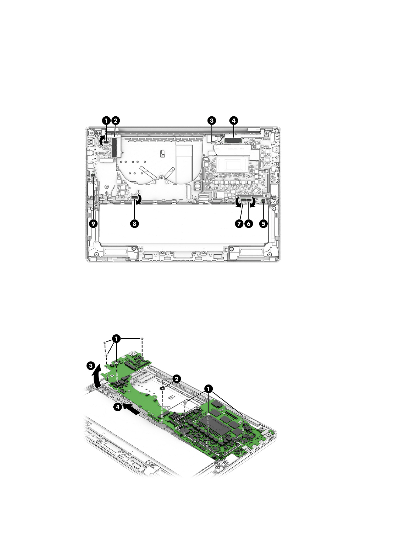
● Right speaker cable (5)
● Right touchpad cable (ZIF) (6)
● Touchpad cable (ZIF) (7)
● NFC cable (ZIF) (8) (select products only)
● Touchpad cable (ZIF) (9)
4. Remove the seven Phillips M2.0 × 2.5 screws (1) from the system board.
5. Remove the Phillips M2.0 × 2.5 screw with hook (2) from the system board.
6. Lift up the left side (3) of the board, and then pull the board (4) to the left and up to remove it from the
computer.
System board
69
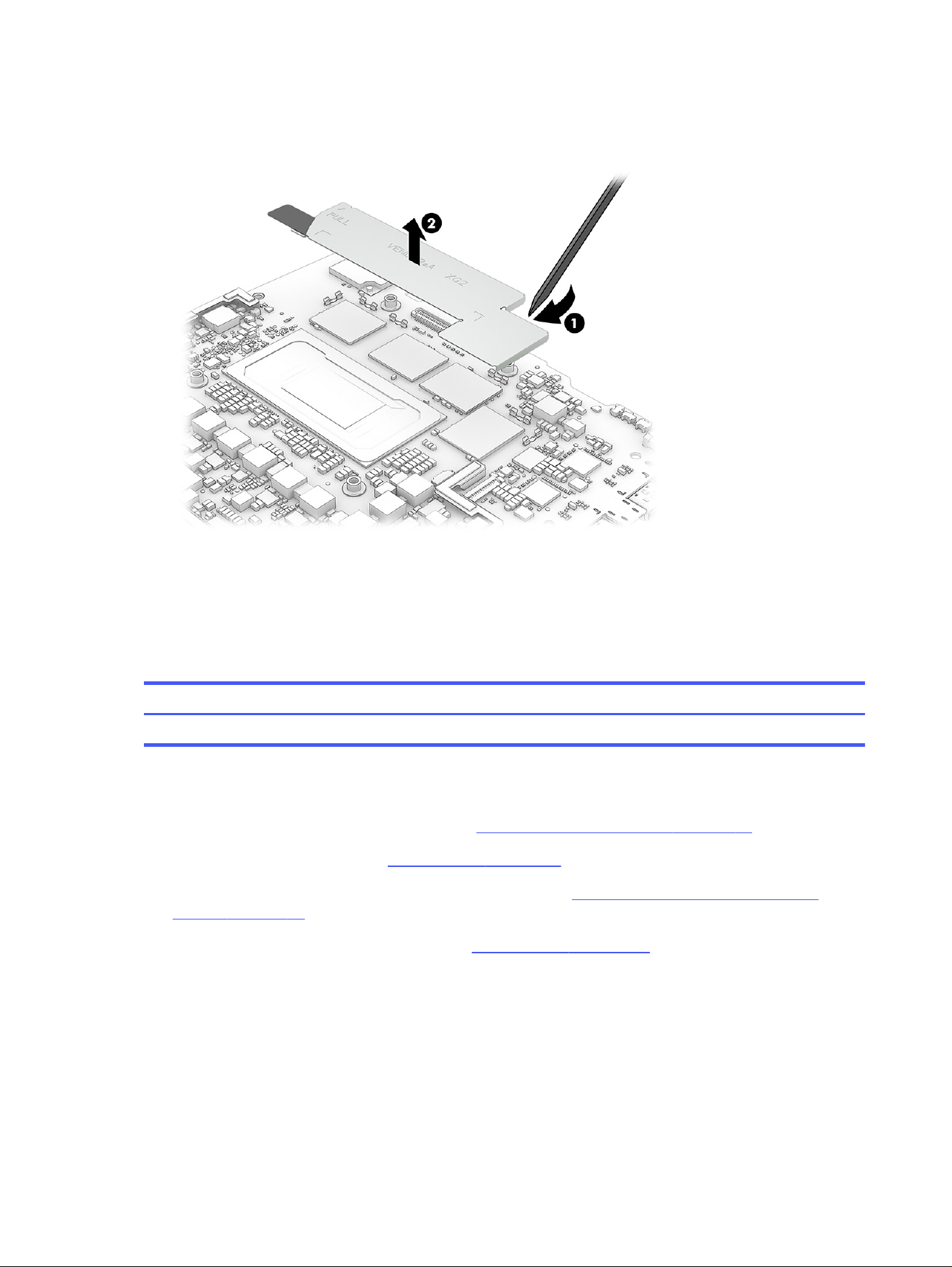
7. When replacing the system board, be sure to remove the memory cover from the old board and
install the cover onto the new board. Use a tool (1) to release the cover, and then lift the cover (2) off
the system board.
Reverse this procedure to install a system board.
Lock bracket
Use this procedure and illustration to remove the lock bracket.
Table 6-7
Lock bracket description and part number
Description Spare part number
Lock bracket 918431-001
Before removing the lock bracket, follow these steps:
1. Prepare the computer for disassembly (see Preparation for disassembly on page 37).
2. Remove the bottom cover (see Bottom cover on page 37).
3. Disconnect the battery cable from the system board (see Removing and reinstalling the same
battery on page 40).
4. Remove the left system board bracket (see System board on page 66).
Remove the lock bracket:
70
Chapter 6 Removal and replacement procedures for authorized service provider parts
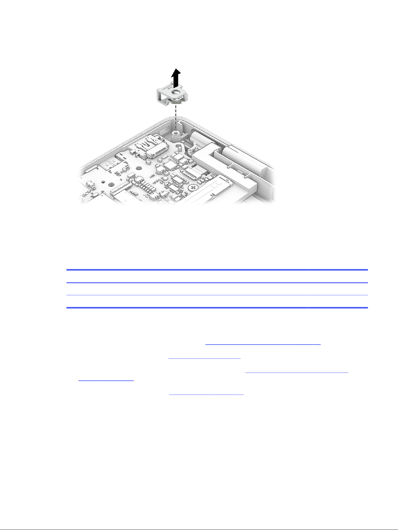
■
Lift the lock bracket out of the computer.
Reverse this procedure to install the lock bracket.
Power button board/fingerprint reader
Use this procedure and illustration to remove the power button board.
Table 6-8
Power button board descriptions and part numbers
Description Spare part number
Glacier silver P87592-001
Atmospheric blue P87593-001
Before removing the power button board, follow these steps:
1. Prepare the computer for disassembly (see Preparation for disassembly on page 37).
2. Remove the bottom cover (see Bottom cover on page 37).
3. Disconnect the battery cable from the system board (see Removing and reinstalling the same
battery on page 40).
4. Remove the system board (see System board on page 66).
Remove the power button board:
1. Remove the two Phillips 2.0 × 2.0 screws (1) from the board.
Power button board/fingerprint reader
71
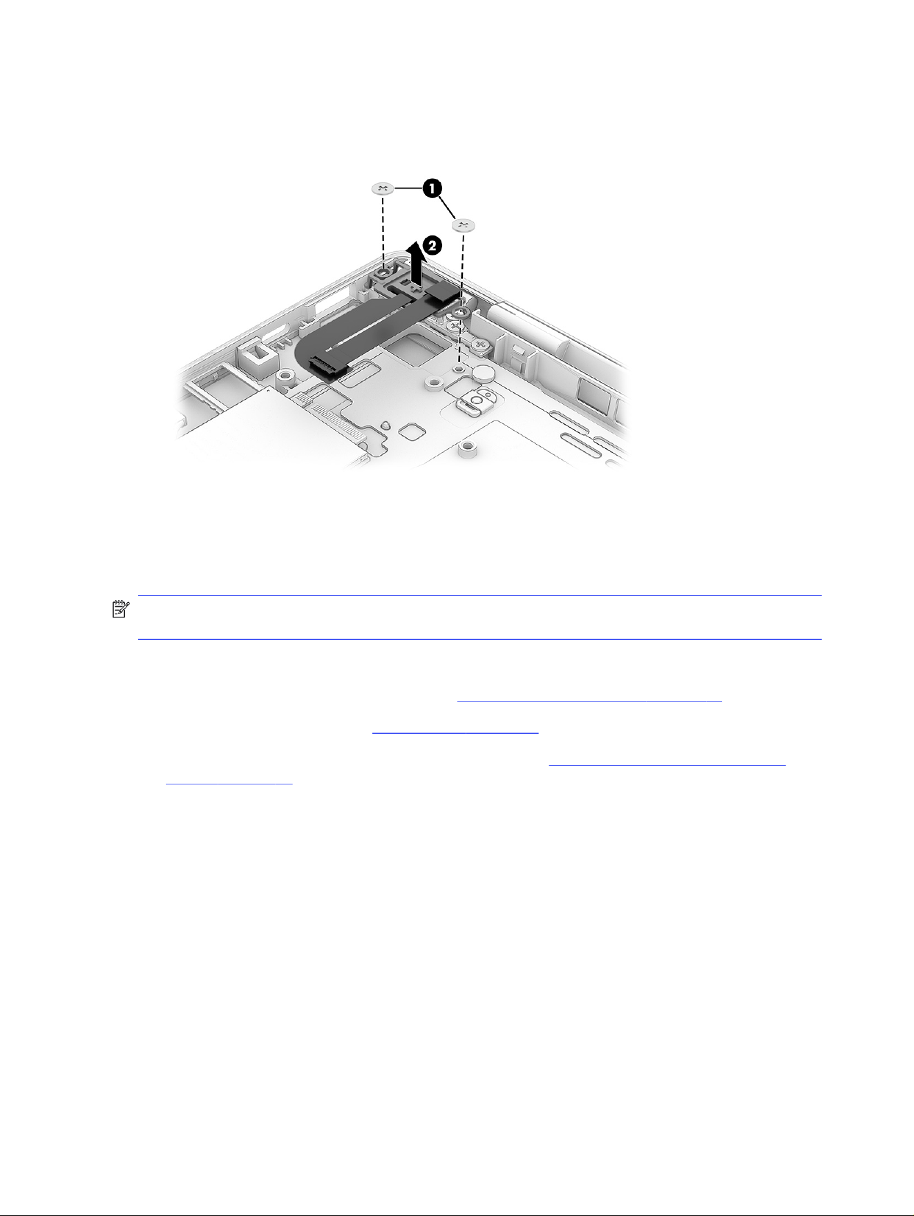
2. Lift the board and cable (2) out of the computer.
Reverse this procedure to install the power button board.
Display assembly
Use these procedures and illustrations to remove the display assembly.
NOTE: The display assembly is only available as a full assembly. Individual spare parts are not
available.
Before removing the display panel, follow these steps:
1. Prepare the computer for disassembly (see Preparation for disassembly on page 37).
2. Remove the bottom cover (see Bottom cover on page 37).
3. Disconnect the battery cable from the system board (see Removing and reinstalling the same
battery on page 40).
Remove the display assembly:
1. Disconnect the camera cable (1) from the system board.
2. Disconnect the antenna cables (2) from the WLAN module.
72
Chapter 6 Removal and replacement procedures for authorized service provider parts
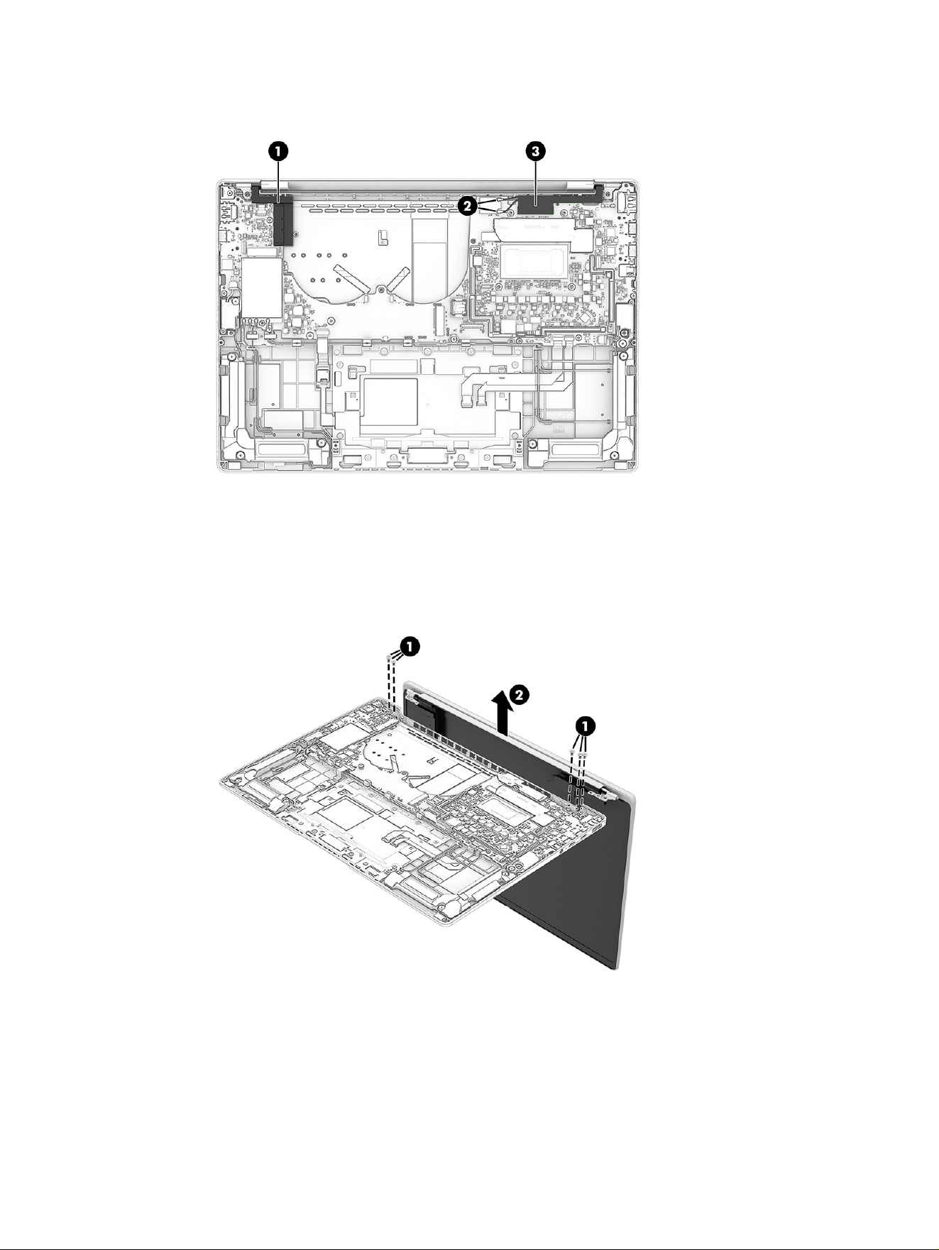
3. Disconnect the display cable (3) from the system board.
4. Open the display and place the computer keyboard-side down with the display hanging down off
the side of a table.
5. Remove the six Phillips M2.5 × 3.5 screws (1) that secure the display assembly to the computer.
6. Separate the display (2) from the computer.
Reverse these procedures to replace the display assembly.
Top cover
The top cover remains after removing all other spare parts from the computer.
Top cover
73

Table 6-9 Top cover descriptions and part numbers
Description Spare part number
Glacier silver, models without WWAN, no pen P86647-001
Glacier silver, models without WWAN, with pen P86648-001
Glacier silver, models with WWAN, no pen P86649-001
Glacier silver, models with WWAN, with pen P86650-001
Atmospheric blue, models without WWAN, no pen P86651-001
Atmospheric blue, models without WWAN, with pen P86652-001
Atmospheric blue, models with WWAN, no pen P86653-001
Atmospheric blue, models with WWAN, with pen P86654-001
74 Chapter 6 Removal and replacement procedures for authorized service provider parts

Using Setup Utility (BIOS)7
Setup Utility, or Basic Input/Output System (BIOS), controls communication between all the input and
output devices on the system (such as disk drives, display, keyboard, mouse, and printer). Setup Utility
(BIOS) includes settings for the types of devices installed, the startup sequence of the computer, and
the amount of system and extended memory.
NOTE: To start Setup Utility on convertible computers, your computer must be in notebook mode and
you must use the keyboard attached to your notebook.
Starting Setup Utility (BIOS)
You have several ways to access the Setup Utility (BIOS).
IMPORTANT: Use extreme care when making changes in Setup Utility (BIOS). Errors can prevent the
computer from operating properly.
Use one of these options:
● Turn on or restart the computer and quickly press f10.
● Turn on or restart the computer, quickly press esc, and then press f10 when the Start menu is
displayed.
Updating Setup Utility (BIOS)
Updated versions of Setup Utility (BIOS) might be available on the HP website. Most BIOS updates on the
HP website are packaged in compressed files called
SoftPaqs
. Some download packages contain a file
named Readme.txt, which contains information regarding installing and troubleshooting the file.
Determining the BIOS version
To decide whether you need to update Setup Utility (BIOS), first determine the BIOS version on your
computer.
To reveal the BIOS version information (also known as
ROM date
and
System BIOS
), use one of these
options.
● HP Support Assistant
1. Perform one of these tasks:
– Select the Search icon in the taskbar, type support in the search box, and then select the
HP Support Assistant app.
– Select the question mark icon in the taskbar.
2. Under My notebook, select Specifications.
● Setup Utility (BIOS)
Using Setup Utility (BIOS)
75

1. Start Setup Utility (BIOS) (see Starting Setup Utility (BIOS) on page 75).
2. Select Main, and then make note of the BIOS version.
3. Select Exit, select one of the options, and then follow the on-screen instructions.
● In Windows, press ctrl+alt+s.
To check for later BIOS versions, see Preparing for a BIOS update on page 76.
Preparing for a BIOS update
Be sure to follow all prerequisites before downloading and installing a BIOS update.
IMPORTANT: To reduce the risk of damage to the computer or an unsuccessful installation, download
and install a BIOS update only when the computer is connected to reliable external power using the HP
AC adapter provided with the computer (select products only), a replacement AC adapter provided by
HP, or an AC adapter with the power rating specified on the product label. Do not download or install a
BIOS update while the computer is running on battery power, docked in an optional docking device, or
connected to an optional power source. During the download and installation, follow these instructions:
● Do not disconnect power from the computer by unplugging the power cord from the AC outlet.
● Do not shut down the computer or initiate Sleep.
● Do not insert, remove, connect, or disconnect any device, cable, or cord.
NOTE: If your computer is connected to a network, consult the network administrator before installing
any software updates, especially system BIOS updates.
Downloading a BIOS update
After you review the prerequisites, you can check for and download BIOS updates.
1. Perform one of these tasks:
● Select the Search icon in the taskbar, type support in the search box, and then select the HP
Support Assistant app.
● Select the question mark icon in the taskbar.
2. Select Updates. The Checking for Updates window opens, and Windows checks for updates.
3. Follow the on-screen instructions.
4. At the download area, follow these steps:
a. Identify the most recent BIOS update and compare it to the BIOS version currently installed on
your computer. If the update is more recent than your BIOS version, make a note of the date,
name, or other identifier. You might need this information to locate the update later, after it has
been downloaded to your hard drive.
b. Follow the on-screen instructions to download your selection to the hard drive.
Make a note of the path to the location on your hard drive where the BIOS update is
downloaded. You will need to access this path when you are ready to install the update.
76
Chapter 7 Using Setup Utility (BIOS)

Installing a BIOS update
BIOS installation procedures vary. Follow any instructions that appear on the screen after the download
is complete. If no instructions appear, follow these steps.
1. Select the Search icon in the taskbar, type file in the search box, and then select File Explorer.
2. Select your hard drive designation. The hard drive designation is typically Local Disk (C:).
3. Using the hard drive path you recorded earlier, open the folder that contains the update.
4. Double-click the file that has an .exe extension (for example,
filename
.exe).
The BIOS installation begins.
5. Complete the installation by following the on-screen instructions.
NOTE: After a message on the screen reports a successful installation, you can delete the
downloaded file from your hard drive.
Installing a BIOS update
77

Using HP PC Hardware Diagnostics8
You can use the HP PC Hardware Diagnostics utility to determine whether your computer hardware
is running properly. The three versions are HP PC Hardware Diagnostics Windows, HP PC Hardware
Diagnostics UEFI (Unified Extensible Firmware Interface), and (for select products only) Remote HP PC
Hardware Diagnostics UEFI, a firmware feature.
Using HP PC Hardware Diagnostics Windows (select products
only)
HP PC Hardware Diagnostics Windows is a Windows-based utility that allows you to run diagnostic tests
to determine whether the computer hardware is functioning properly. The tool runs within the Windows
operating system to diagnose hardware failures.
If HP PC Hardware Diagnostics Windows is not installed on your computer, you must download and
install it. To download HP PC Hardware Diagnostics Windows, see Downloading HP PC Hardware
Diagnostics Windows on page 79.
Using an HP PC Hardware Diagnostics Windows hardware failure ID code
When HP PC Hardware Diagnostics Windows detects a failure that requires hardware replacement, a
24-digit failure ID code is generated for select component tests. For interactive tests, such as keyboard,
mouse, or audio and video palette, you must perform troubleshooting steps before you can receive a
failure ID.
You have several options after you receive a failure ID:
● Select Next to open the Event Automation Service (EAS) page, where you can log the case.
● Scan the QR code with your mobile device, which takes you to the EAS page, where you can log the
case.
● Select the box next to the 24-digit failure ID to copy your failure code and send it to support.
Accessing HP PC Hardware Diagnostics Windows
After HP PC Hardware Diagnostics Windows is installed, you can access it from HP Support Assistant or
the Start menu.
Accessing HP PC Hardware Diagnostics Windows from HP Support Assistant (select products
only)
After HP PC Hardware Diagnostics Windows is installed, follow these steps to access it from HP Support
Assistant.
1. Complete one of the following tasks:
● Select the Search icon in the taskbar, type support in the search box, and then select the HP
Support Assistant app.
● Select the question mark icon in the taskbar.
78
Chapter 8 Using HP PC Hardware Diagnostics

2. Select Fixes & Diagnostics.
3. Select Run hardware diagnostics, and then select Launch.
4. When the tool opens, select the type of diagnostic test that you want to run, and then follow the
on-screen instructions.
NOTE: To stop a diagnostic test, select Cancel.
Accessing HP PC Hardware Diagnostics Windows from the Start menu (select products only)
After HP PC Hardware Diagnostics Windows is installed, follow these steps to access it from the Start
menu.
1. Select the Start button, and then select All apps.
2. Select HP PC Hardware Diagnostics Windows.
3. When the tool opens, select the type of diagnostic test that you want to run, and then follow the
on-screen instructions.
NOTE: To stop a diagnostic test, select Cancel.
Downloading HP PC Hardware Diagnostics Windows
The HP PC Hardware Diagnostics Windows downloading instructions are provided in English only. You
must use a Windows computer to download this tool because only .exe files are provided.
Downloading the latest HP PC Hardware Diagnostics Windows version from HP
To download HP PC Hardware Diagnostics Windows from HP, follow these steps.
1. Go to http://www.hp.com/go/techcenter/pcdiags. The HP PC Diagnostics home page is displayed.
2. Select Diagnose PC Hardware issues in Windows, scroll down to the expanded window that
appears, and then select Download.
3. A pop-up that asks what you want to do with the file opens. Select Open or Save As. The latest
version of the diagnostics tool opens or downloads to the selected location.
Downloading the HP PC Hardware Diagnostics Windows from the Microsoft Store
You can download the HP PC Hardware Diagnostics Windows from the Microsoft Store.
1. Select the Microsoft Store app on your desktop or select the Search icon in the taskbar, and then
type Microsoft Store in the search box.
2. Type HP PC Hardware Diagnostics Windows in the Microsoft Store search box.
3. Follow the on-screen directions.
The tool downloads to the selected location.
Accessing HP PC Hardware Diagnostics Windows from the Start menu (select products only)
79

Downloading HP Hardware Diagnostics Windows by product name or number (select products
only)
You can download HP PC Hardware Diagnostics Windows by product name or number.
NOTE: For some products, you might have to download the software to a USB flash drive by using the
product name or number.
1. Go to http://www.hp.com/support.
2. Select Software and Drivers, select your type of product, and then enter the product name or
number in the search box that is displayed.
3. In the Diagnostics section, select Download, and then follow the on-screen instructions to select
the specific Windows diagnostics version to be downloaded to your computer or USB flash drive.
The tool downloads to the selected location.
Installing HP PC Hardware Diagnostics Windows
To install HP PC Hardware Diagnostics Windows, navigate to the folder on your computer or the USB
flash drive where the .exe file downloaded, double-click the .exe file, and then follow the on-screen
instructions.
Using HP PC Hardware Diagnostics UEFI
HP PC Hardware Diagnostics Unified Extensible Firmware Interface (UEFI) allows you to run diagnostic
tests to determine whether the computer hardware is functioning properly. The tool runs outside the
operating system so that it can isolate hardware failures from issues that are caused by the operating
system or other software components.
NOTE: For some products, you must use a Windows computer and a USB flash drive to download and
create the HP UEFI support environment because only .exe files are provided. For more information,
see Downloading HP PC Hardware Diagnostics UEFI to a USB flash drive on page 81.
If your PC does not start in Windows, you can use HP PC Hardware Diagnostics UEFI to diagnose
hardware issues.
Using an HP PC Hardware Diagnostics UEFI hardware failure ID code
When HP PC Hardware Diagnostics UEFI detects a failure that requires hardware replacement, a 24-digit
failure ID code is generated.
For assistance in solving the problem, complete one of these tasks:
● Select Contact HP, accept the HP privacy disclaimer, and then use a mobile device to scan the
failure ID code that appears on the next screen. The HP Customer Support - Service Center
page appears with your failure ID and product number automatically filled in. Follow the on-screen
instructions.
● Contact support, and provide the failure ID code.
Starting HP PC Hardware Diagnostics UEFI
To start HP PC Hardware Diagnostics UEFI, follow this procedure.
80
Chapter 8 Using HP PC Hardware Diagnostics

1. Turn on or restart the computer, and quickly press esc.
2. Press f2.
The BIOS searches three places for the diagnostic tools, in the following order:
a. Connected USB flash drive
NOTE: To download the HP PC Hardware Diagnostics UEFI tool to a USB flash drive, see
Downloading the latest HP PC Hardware Diagnostics UEFI version on page 82.
b. Hard drive
c. BIOS
3. When the diagnostic tool opens, select the type of diagnostic test that you want to run, and then
follow the on-screen instructions.
Starting HP PC Hardware Diagnostics UEFI through HP Hotkey Support software
(select products only)
This section describes how to start HP PC Hardware Diagnostics UEFI through HP Hotkey Support
software.
NOTE: You must disable Fast Boot to access HP PC Hardware Diagnostics UEFI from the HP System
Information application.
To disable Fast Boot:
1. Turn on or restart the computer, and when the HP logo appears, press f10 to enter Computer Setup.
2. Select Advanced, and then select Boot Options.
3. Clear Fast Boot.
4. Select Save Changes and Exit, and then select Yes.
To start HP PC Hardware Diagnostics UEFI through HP Hotkey Support software, follow this procedure:
1. From the Start menu, open the HP System Information Application or press fn+esc.
2. In HP System Information screen, select Run System Diagnostics, select Yes to run the application,
and then select Restart.
IMPORTANT: To prevent loss of data, save your work in all open apps before restarting your computer.
NOTE: When the restart is complete, the computer opens the HP PC Hardware Diagnostics UEFI
Application. Proceed with the troubleshooting tests.
Downloading HP PC Hardware Diagnostics UEFI to a USB flash drive
Downloading HP PC Hardware Diagnostics UEFI to a USB flash drive can be useful in some situations.
● HP PC Hardware Diagnostics UEFI is not included in the preinstallation image.
● HP PC Hardware Diagnostics UEFI is not included in the HP Tool partition.
Starting HP PC Hardware Diagnostics UEFI through HP Hotkey Support software (select products only)
81

● The hard drive is damaged.
NOTE: The HP PC Hardware Diagnostics UEFI downloading instructions are provided in English only,
and you must use a Windows computer to download and create the HP UEFI support environment
because only .exe files are provided.
Downloading the latest HP PC Hardware Diagnostics UEFI version
To download the latest HP PC Hardware Diagnostics UEFI version to a USB flash drive, follow these
steps.
1. Go to http://www.hp.com/go/techcenter/pcdiags. The HP PC Diagnostics home page is displayed.
2. Select Diagnose PC Hardware Issues outside of the OS, scroll down to the expanded window that
appears, and then select Download.
3. A pop-up that asks what you want to do with the file opens. Select Open or Save As. The latest
version of the diagnostics tool opens or downloads to the selected location.
Downloading HP PC Hardware Diagnostics UEFI by product name or number (select products
only)
You can download HP PC Hardware Diagnostics UEFI by product name or number (select products only)
to a USB flash drive.
NOTE: For some products, you might have to download the software to a USB flash drive by using the
product name or number.
1. Go to http://www.hp.com/support.
2. Enter the product name or number, select your computer, and then select your operating system.
3. In the Diagnostics section, follow the on-screen instructions to select and download the specific
UEFI Diagnostics version for your computer.
Using Remote HP PC Hardware Diagnostics UEFI settings
(select products only)
Remote HP PC Hardware Diagnostics UEFI is a firmware (BIOS) feature that downloads HP PC Hardware
Diagnostics UEFI to your computer. It can then run the diagnostics on your computer, and it might upload
results to a preconfigured server.
For more information about Remote HP PC Hardware Diagnostics UEFI, go to
http://www.hp.com/go/techcenter/pcdiags, select Diagnose Other Potential Issues, scroll down to
Remote PC Hardware Diagnostics UEFI, and then select Learn More.
Downloading Remote HP PC Hardware Diagnostics UEFI
Remote HP PC Hardware Diagnostics UEFI is also available as a SoftPaq that you can download to a
server.
Downloading the latest Remote HP PC Hardware Diagnostics UEFI version
You can download the latest Remote HP PC Hardware Diagnostics UEFI version to a USB flash drive.
1. Go to http://www.hp.com/go/techcenter/pcdiags. The HP PC Diagnostics home page is displayed.
82
Chapter 8 Using HP PC Hardware Diagnostics

2. Select Diagnose PC Hardware Issues outside of the OS, scroll down to the expanded window that
appears, and then select Download.
3. A pop-up that asks what you want to do with the file opens. Select Open or Save As. The latest
version of the diagnostics tool opens or downloads to the selected location.
Downloading Remote HP PC Hardware Diagnostics UEFI by product name or number
You can download Remote HP PC Hardware Diagnostics UEFI by product name or number.
NOTE: For some products, you might have to download the software by using the product name or
number.
1. Go to http://www.hp.com/support.
2. Select Software and Drivers, select your type of product, enter the product name or number in the
search box that is displayed, select your computer, and then select your operating system.
3. In the Diagnostics section, follow the on-screen instructions to select and download the Remote
UEFI version for the product.
Customizing Remote HP PC Hardware Diagnostics UEFI settings
Using the Remote HP PC Hardware Diagnostics setting in Computer Setup (BIOS), you can perform
several customizations.
● Set a schedule for running diagnostics unattended. You can also start diagnostics immediately in
interactive mode by selecting Execute Remote HP PC Hardware Diagnostics UEFI.
● Set the location for downloading the diagnostic tools. This feature provides access to the tools
from the HP website or from a server that has been preconfigured for use. Your computer does
not require the traditional local storage, such as a hard drive or USB flash drive, to run remote
diagnostics.
● Set a location for storing the test results. You can also set the user name and password that you use
for uploads.
● Display status information about the diagnostics run previously.
To customize Remote HP PC Hardware Diagnostics UEFI settings, follow these steps:
1. Turn on or restart the computer, and when the HP logo appears, press f10 to enter Computer Setup.
2. Select Advanced, and then select Settings.
3. Make your customization selections.
4. Select Main, then select Save Changes and Exit to save your settings.
Your changes take effect when the computer restarts.
Downloading Remote HP PC Hardware Diagnostics UEFI by product name or number
83

Backing up, restoring, and recovering9
You can use Windows tools or HP software to back up your information, create a restore point, reset
your computer, create recovery media, or restore your computer to its factory state. Performing these
standard procedures can return your computer to a working state faster.
IMPORTANT: If you are performing recovery procedures on a tablet, the tablet battery must be at
least 70% charged before you start the recovery process.
IMPORTANT: For a tablet with a detachable keyboard, connect the tablet to the keyboard base before
beginning any recovery process.
Backing up information and creating recovery media
These methods of creating recovery media and backups are available on select products only.
Using Windows tools for backing up
HP recommends that you back up your information immediately after initial setup. You can do this task
either using Windows Backup locally with an external USB flash drive or using online tools.
NOTE: If computer storage is 32 GB or less, Microsoft System Restore is disabled by default.
Using the HP Cloud Recovery Download Tool to create a recovery USB flash drive
(select products only)
You can use the HP Cloud Recovery Download Tool to create an HP Recovery bootable USB flash drive.
For details:
■
Go to http://www.hp.com, search for HP Cloud Recovery, and then select the result that matches the
type of computer that you have and follow the on-screen instructions.
NOTE: In select countries, if you cannot create the HP Recovery USB flash drive yourself, contact
support. Go to http://www.hp.com/support, select your country or region, and then follow the on-screen
instructions.
IMPORTANT: HP recommends that you follow the Restoring and recovery methods on page 85 to
restore your computer before you obtain and use the HP USB flash drive. Using a recent backup can
return your machine to a working state sooner than using the HP USB flash drive. After the system is
restored, reinstalling all the operating system software released since your initial purchase can be a
lengthy process.
Restoring and recovering your system
You have several tools available to recover your system both within and outside of Windows if the
desktop cannot load.
84
Chapter 9 Backing up, restoring, and recovering

HP recommends that you attempt to restore your system using the Restoring and recovery methods on
page 85.
Creating a system restore
System Restore is available in Windows. The System Restore software can automatically or manually
create restore points, or snapshots, of the system files and settings on the computer at a particular
point.
When you use System Restore, it returns your computer to its state at the time you made the restore
point. Your personal files and documents should not be affected.
Restoring and recovery methods
After you run the first method, test to see whether the issue still exists before you proceed to the next
method, which might now be unnecessary.
1. Run a Microsoft System Restore.
2. Run Reset this PC.
NOTE: The options Remove everything and then Fully clean the drive can take several hours to
complete and leave no information on your computer. It is the safest way to reset your computer
before you recycle it.
3. Recover using the HP Recovery USB flash drive. For more information, see Recovering using the HP
Recovery USB flash drive on page 85.
For more information about the first two methods, see the Get Help app:
■
Select the Start button, select All apps, select the Get Help app, and then enter the task you want to
perform.
NOTE: You must be connected to the internet to access the Get Help app.
Recovering using the HP Recovery USB flash drive
You can use the HP Recovery USB flash drive to recover the operating system and drivers that were
installed at the factory. On select products, you can create recovery media on a bootable USB flash
drive using the HP Cloud Recovery Download Tool.
For details, see Using the HP Cloud Recovery Download Tool to create a recovery USB flash drive (select
products only) on page 84.
NOTE: In select countries, if you cannot create the HP Recovery USB flash drive yourself, contact
support. Go to http://www.hp.com/support, select your country or region, and then follow the on-screen
instructions.
To recover your system:
■
Insert the HP Recovery USB flash drive, and then restart the computer.
NOTE: HP recommends that you follow the Restoring and recovery methods on page 85 to restore
your computer before you obtain and use the HP USB flash drive. Using a recent backup can return
your machine to a working state sooner than using the HP USB flash drive. After the system is restored,
reinstalling all the operating system software released since your initial purchase can be a lengthy
process.
Creating a system restore
85

Changing the computer boot order
If your computer does not restart using the HP Recovery USB flash drive, you can change the computer
boot order, which is the order of devices listed in BIOS for startup information.
IMPORTANT: For a tablet with a detachable keyboard, connect the tablet to the keyboard base before
beginning these steps.
To change the boot order:
1. Insert the HP Recovery USB flash drive.
2. Access the system Startup menu.
● For computers or tablets with keyboards attached, turn on or restart the computer or tablet,
quickly press esc, and then press f9 for boot options.
● For tablets without keyboards, turn on or restart the tablet, and then quickly press and hold one
of the following buttons:
– Volume up
– Volume down
Then select f9.
3. Select the USB flash drive to boot from, and then follow the on-screen instructions.
Using HP Sure Recover (select products only)
Select computer models are configured with HP Sure Recover, a PC operating system (OS) recovery
solution built into the hardware and software. HP Sure Recover can fully restore the HP OS image
without installed recovery software.
Using HP Sure Recover, an administrator or user can restore the system and install:
● Latest version of the OS
● Platform-specific device drivers
● Software applications, in the case of a custom image
To access the latest documentation for HP Sure Recover, go to http://www.hp.com/support. Follow the
on-screen instructions to find your product and locate your documentation.
86
Chapter 9 Backing up, restoring, and recovering

Specifications10
This chapter provides specifications for your computer system.
Computer specifications
This section provides specifications for your computer. When you travel with your computer, the
computer dimensions and weights, as well as input power ratings and operating specifications, provide
helpful information.
Table 10-1
Computer specifications
Metric U.S.
Dimensions
Width 312.7 mm 12.31 in
Depth 219.9 mm 8.66 in
Height (front) 7.9 mm 0.31 in
Height (rear) 13.16 mm 0.52 in
Weight (lowest) 1299 g 2.86 lbs
Input power
Operating voltage and current 5 V DC @ 3 A / 9 V DC @ 3 A / 12 V DC @ 5 A / 15 V DC @ 5 A / 20 V DC @
5 A – 100 W USB-C
5 V DC @ 3 A / 9 V DC @ 3 A / 12 V DC @ 5 A / 15 V DC @ 4.33 A / 20 V DC
@ 3.25 A – 65 W USB-C
5 V DC @ 3 A / 9 V DC @ 3 A / 10 V DC @ 5 A / 12 V DC @ 5 A / 15 V DC @
4.33 A / 20 V DC @ 3.25 A – 65 W USB-C
5 V DC @ 3 A / 9 V DC @ 3 A / 12 V DC @ 3.75 A /15 V DC @ 3 A – 45 W
USB-C
5 V DC @ 3 A / 9 V DC @ 3 A / 10 V DC @ 3.75 A / 12 V DC @ 3.75 A / 15 V
DC @ 3 A / 20 V DC @ 2.25 A – 45 W USB-C
Temperature
Operating 5°C to 35°C 41°F to 95°F
Nonoperating –20°C to 60°C –4°F to 140°F
Relative humidity (noncondensing)
Operating 10% to 90%
Nonoperating 5% to 95%
Maximum altitude (unpressurized)
Operating –15 m to 3,048 m –50 ft to 10,000 ft
Specifications 87

Table 10-1 Computer specifications (continued)
Metric U.S.
Nonoperating –15 m to 12,192 m –50 ft to 40,000 ft
NOTE: Applicable product safety standards specify thermal limits for plastic surfaces. The device
operates well within this range of temperatures.
Display specifications
This section provides specifications for your display.
Table 10-2
Display specifications
Metric U.S.
Active diagonal size 35.6 cm 14.0 in
Resolution 2880 × 1800 (2.8 K)
1920 × 1200 (WUXGA)
Surface treatment BrightView (OLED)
Antiglare (3 K, WUXGA)
Brightness 300 nits (WUXGA)
400 nits (WUXGA)
500 nits (3 K, UUXGA)
700 nits (3 K)
800 nits (WUXGA)
Viewing angle UWVA
Backlight OLED
LED
Display panel interface eDP
Solid-state drive specifications
This section provides specifications for your SSDs.
Table 10-3
SSD specifications
512 GB* 1 TB* 2 TB*
Dimensions
Height 1.0 mm 1.0 mm 1.0 mm
Length 50.8 mm 50.8 mm 50.8 mm
Width 28.9 mm 28.9 mm 28.9 mm
88 Chapter 10 Specifications

Table 10-3 SSD specifications (continued)
512 GB* 1 TB* 2 TB*
Weight < 10 g < 10 g < 10 g
Interface type PCIe PCIe PCIe
Ready time, maximum (to not busy) < 1.0 ms 1.0 ms 1.0 ms
Access times, logical 0.1 ms 0.1 ms 0.1 ms
Transfer rate
Sequential read up to 2150 MBps up to 2150 MBps up to 3800 MBps
Random read Up to 300,000 IOPs Up to 300,000 IOPs Up to 300,000 IOPs
Sequential write up to 1550 MBps up to 1550 MBps up to 2670 MBps
Random write Up to 100,000 IOPs Up to 100,000 IOPs Up to 100,000 IOPs
Total logical sectors 1,000,215,216 1,500,336,388 2,998,846
Operating temperature 0°C to 70°C
(32°F to 158°F)
0°C to 70°C
(32°F to 158°F)
0°C to 70°C
(32°F to 158°F)
*Actual accessible capacity is less. Actual drive specifications might differ slightly.
Certain restrictions and exclusions apply. Contact support for details.
Solid-state drive specifications
89

Statement of memory volatility11
For general information regarding nonvolatile memory in HP business computers, and to restore
nonvolatile memory that can contain personal data after the system has been turned off and the hard
drive has been removed, use these instructions.
HP business computer products that use Intel-based or AMD-based system boards contain volatile
DDR memory. The amount of nonvolatile memory present in the system depends upon the system
configuration. Intel-based and AMD-based system boards contain nonvolatile memory subcomponents
as originally shipped from HP, with the following assumptions:
● No subsequent modifications were made to the system.
● No applications, features, or functionality were added to or installed on the system.
Following system shutdown and removal of all power sources from an HP business computer system,
personal data can remain on volatile system memory (DIMMs) for a finite period of time and also
remains in nonvolatile memory. Use the following steps to remove personal data from the computer,
including the nonvolatile memory found in Intel-based and AMD-based system boards.
NOTE: If your tablet has a keyboard base, connect to the keyboard base before beginning steps in this
chapter.
Current BIOS steps
Use these instructions to restore nonvolatile memory.
1. Follow these steps to restore the nonvolatile memory that can contain personal data. Restoring
or reprogramming nonvolatile memory that does not store personal data is neither necessary nor
recommended.
a. Turn on or restart the computer, and then quickly press esc.
NOTE: If the system has a BIOS administrator password, type the password at the prompt.
b. Select Main, select Apply Factory Defaults and Exit, and then select Yes to load defaults. The
computer restarts.
c. During the restart, press esc while the "Press the ESC key for Startup Menu" message is
displayed at the bottom of the screen.
NOTE: If the system has a BIOS administrator password, type the password at the prompt.
d. Select the Security menu, select Restore Security Settings to Factory Defaults, and then
select Yes to restore security level defaults. The computer restarts.
e. During the restart, press esc while the "Press the ESC key for Startup Menu" message is
displayed at the bottom of the screen.
NOTE: If the system has a BIOS administrator password, type the password at the prompt.
90
Chapter 11 Statement of memory volatility

f. If an asset or ownership tag is set, select the Security menu and scroll down to the Utilities
menu. Select System IDs, and then select Asset Tracking Number. Clear the tag, and then
make the selection to return to the prior menu.
g. If a DriveLock password is set, select the Security menu, and scroll down to Hard Drive Utilities
under the Utilities menu. Select Hard Drive Utilities, select DriveLock, and then clear the check
box for DriveLock password on restart. Select OK to proceed.
h. Select the Main menu, and then select Reset BIOS Security to factory default. Select Yes at
the warning message. The computer restarts.
i. During the restart, press esc while the "Press the ESC key for Startup Menu" message is
displayed at the bottom of the screen.
NOTE: If the system has a BIOS administrator password, type the password at the prompt.
j. Select the Main menu, select Apply Factory Defaults and Exit, select Yes to save changes and
exit, and then select Shutdown.
k. Restart the system. If the system has a TPM, fingerprint reader, or both, one or two prompts
will appear—one to clear the TPM and the other to Reset Fingerprint Sensor. Press or tap f1 to
accept or f2 to reject.
l. Remove all power and system batteries for at least 24 hours.
2. Complete one of the following tasks:
● Remove and retain the storage drive.
● Clear the drive contents by using a third-party utility designed to erase data from an SSD.
● Clear the contents of the drive by using the following BIOS Setup Secure Erase command
option steps:
NOTE: If you clear data using Secure Erase, you cannot recover it.
a. Turn on or restart the computer, and then quickly press esc.
b. Select the Security menu and scroll down to the esc menu.
c. Select Hard Drive Utilities.
d. Finish by completing one of these tasks:
● Under Utilities, select Secure Erase, select the hard drive storing the data you want to
clear, and then follow the on-screen instructions to continue.
● Clear the contents of the drive using the following Disk Sanitizer commands steps:
i. Turn on or restart the computer, and then quickly press esc.
ii. Select the Security menu and scroll down to the Utilities menu.
iii. Select Hard Drive Utilities.
Current BIOS steps
91

iv. Under Utilities, select Disk Sanitizer, select the hard drive with the data that you want
to clear, and then follow the on-screen instructions to continue.
NOTE: The amount of time it takes for Disk Sanitizer to run can be several hours.
Plug the computer into an AC outlet before starting.
Nonvolatile memory usage
Use this table to troubleshoot nonvolatile memory usage.
Table 11-1 Troubleshooting information for nonvolatile memory usage
Description Volatility description Storage user data How to erase
Primary storage device, holds the
OS, applications, and application
settings
Nonvolatile, 8-256 GB of
eMMC or NVMe SSD storage,
removable
Yes
1
See Current BIOS steps
on page 90 for information
about erasing the primary
storage device.
System memory (RAM), holds
transient data during system
operation
Volatile, SODIMM socket.
Removable (4 GB/8 GB/16 GB)
Yes Unplug unit from power.
Permanent system BIOS settings Nonvolatile, 16 KB, stored
No
2
See Current BIOS steps
on page 90 for information
about clearing BIOS settings.
System boot ROM (BIOS) Nonvolatile memory, 128 Mbit
(16 MB) socketed, removable
No Download the latest BIOS
for your model from the
HP website and follow the
instructions to flash the BIOS
that are on the website.
RTC (CMOS) RAM Volatile memory, 256 bytes
located in AMD embedded
System on Chip (SoC)
No Desktop computers with a
CMOS button:
Unplug unit from main power,
remove top cover and press
the Clear CMOS button.
Notebook and desktop
computers without a CMOS
button:
1. Press and hold power
button for 12 seconds.
2. Press Windows key + V,
and then press power
button.
Keyboard/mouse (ROM) Nonvolatile, 2 KB embedded in
the super I/O controller (SIO2)
Yes N/A
Keyboard/mouse (RAM) Volatile, 256 bytes embedded in
the super I/O controller (SIO2)
No Unplug unit from main power.
LOM EEPROM Nonvolatile, 2 MB embedded in
LAN controller
No N/A
TPM Nonvolatile, 51 KB ROM for
firmware and 38 KB system
parametric data
No
3
See Current BIOS steps
on page 90 for information
about clearing TPM.
92 Chapter 11 Statement of memory volatility

1
Under typical operation, the only user data stored on the primary storage device are preferences for
device configuration and settings for connections. However, the administrator can configure the system
to allow users to store data locally.
2
The only user data potentially stored in BIOS Settings are the ownership and asset tags, administrator
password, and startup password.
3
The TPM might contain encrypted passwords or certificates generated from user or administrator
input.
Questions and answers
Use this section to answer your questions about nonvolatile memory.
1. How can the BIOS settings be restored (returned to factory settings)?
IMPORTANT: The restore defaults feature does not securely erase any information on your hard
drive. See question and answer 6 for steps to securely erase information.
The restore defaults feature does not reset the Custom Secure Boot keys. See question and
answer 7 for information about resetting the keys.
a. Turn on or restart the computer, and then quickly press esc.
b. Select Main, and then select Apply Factory Defaults and Exit.
c. Follow the on-screen instructions.
d. Select Main, select Save Changes and Exit, and then follow the on-screen instructions.
2. What is a UEFI BIOS?
The Unified Extensible Firmware Interface (UEFI) BIOS is an industry-standard software interface
between the platform firmware and an operating system (OS). It replaces the older legacy BIOS
architecture.
The UEFI BIOS provides an interface to display the system information and configuration settings
and to change the configuration of your computer before an OS is loaded. BIOS provides a secure
runtime environment that supports a GUI. In this environment, you can use either a pointing device
(touch screen, touchpad, pointing stick, or USB mouse) or the keyboard to navigate and make menu
and configuration selections. The UEFI BIOS also contains basic system diagnostics.
In addition, the UEFI BIOS works to initialize the computer’s hardware before loading and executing
the OS; the runtime environment allows the loading and execution of software programs from
storage devices to provide more functionality, such as advanced hardware diagnostics (with the
ability to display more detailed system information) and advanced firmware management and
recovery software.
3. Where is the UEFI BIOS located?
The UEFI BIOS is located on a flash memory chip. You must use a utility to write to the chip.
4. What kind of configuration data is stored on the DIMM Serial Presence Detect (SPD) memory
module? How would this data be written?
Questions and answers
93

The DIMM SPD memory contains information about the memory module, such as size, serial
number, data width, speed and timing, voltage, and thermal information. This information is written
by the module manufacturer and stored on an EEPROM. You cannot write to this EEPROM when the
memory module is installed in a computer. Third-party tools do exist that can write to the EEPROM
when the memory module is not installed in a computer. Various third-party tools are available to
read SPD memory.
5. What is meant by “Restore the nonvolatile memory found in Intel-based system boards”?
This message relates to clearing the Real Time Clock (RTC) CMOS memory that contains computer
configuration data.
6. How can the BIOS security be reset to factory defaults and erase the data?
IMPORTANT: Resetting results in the loss of information.
These steps do not reset Custom Secure Boot Keys. See question and answer 7 for information
about resetting the keys.
a. Turn on or restart the computer, and then quickly press esc.
b. Select Main, and then select Reset Security to Factory Defaults.
c. Follow the on-screen instructions.
d. Select Main, select Save Changes and Exit, and then follow the on-screen instructions.
7. How can the Custom Secure Boot Keys be reset?
Secure Boot is a feature to ensure that only authenticated code can start on a platform. If you
enabled Secure Boot and created Custom Secure Boot Keys, disabling Secure Boot does not clear
the keys. You must also select to clear the Custom Secure Boot Keys. Use the same Secure Boot
access procedure that you used to create the Custom Secure Boot Keys, but select to clear or
delete all Secure Boot Keys.
a. Turn on or restart the computer, and then quickly press esc.
b. Select the Security menu, select Secure Boot Configuration, and then follow the on-screen
instructions.
c. At the Secure Boot Configuration window, select Secure Boot, select Clear Secure Boot Keys,
and then follow the on-screen instructions to continue.
Using HP Sure Start (select products only)
Select computer models are configured with HP Sure Start, a technology that monitors the computer's
BIOS for attacks or corruption. If the BIOS becomes corrupted or is attacked, HP Sure Start
automatically restores the BIOS to its previously safe state, without user intervention.
HP Sure Start is configured and already enabled so that most users can use the HP Sure Start default
configuration. Advanced users can customize the default configuration.
To access the latest documentation on HP Sure Start, go to http://www.hp.com/support. Select Find your
product, and then follow the on-screen instructions.
94
Chapter 11 Statement of memory volatility

Power cord set requirements12
This chapter provides power cord requirements for countries and regions.
The wide-range input feature of the computer permits it to operate from any line voltage from 100 V AC
to 120 V AC, or from 220 V AC to 240 V AC.
The 3-conductor power cord set included with the computer meets the requirements for use in the
country or region where the equipment is purchased.
Power cord sets for use in other countries or regions must meet the requirements of the country and
region where the computer is used.
Requirements for all countries
These power cord requirements are applicable to all countries and regions.
● The length of the power cord set must be at least 1.0 m (3.3 ft) and no more than 2.0 m (6.5 ft).
● All power cord sets must be approved by an acceptable accredited agency responsible for
evaluation in the country or region where the power cord set will be used.
● The power cord sets must have a minimum current capacity of 10 A and a nominal voltage rating of
125 V AC or 250 V AC, as required by the power system of each country or region.
● The appliance coupler must meet the mechanical configuration of an EN 60 320/IEC 320 Standard
Sheet C13 connector for mating with the appliance inlet on the back of the computer.
Requirements for specific countries and regions
To determine power cord requirements for specific countries and regions, use this table.
Table 12-1
Power cord requirements for specific countries and regions
Country/region Accredited agency Applicable note number
Argentina IRAM 1
Australia SAA 1
Austria OVE 1
Belgium CEBEC 1
Brazil ABNT 1
Canada CSA 2
Chile IMQ 1
Denmark DEMKO 1
Finland FIMKO 1
France UTE 1
Power cord set requirements 95

Table 12-1 Power cord requirements for specific countries and regions (continued)
Country/region Accredited agency Applicable note number
Germany VDE 1
India BIS 1
Israel SII 1
Italy IMQ 1
Japan JIS 3
Netherlands KEMA 1
New Zealand SANZ 1
Norway NEMKO 1
The People’s Republic of China CCC 4
Saudi Arabia SASO 7
Singapore PSB 1
South Africa SABS 1
South Korea KTL 5
Sweden SEMKO 1
Switzerland SEV 1
Taiwan BSMI 6
Thailand TISI 1
United Kingdom ASTA 1
United States UL 2
1. The flexible cord must be Type HO5VV-F, 3-conductor, 0.75 mm² conductor size. Power cord set
fittings (appliance coupler and wall plug) must bear the certification mark of the agency responsible
for evaluation in the country or region where it will be used.
2. The flexible cord must be Type SVT/SJT or equivalent, No. 18 AWG, 3-conductor. The wall plug must
be a 2-pole grounding type with a NEMA 5-15P (15 A, 125 V AC) or NEMA 6-15P (15 A, 250 V AC)
configuration. CSA or C-UL mark. UL file number must be on each element.
3. The appliance coupler, flexible cord, and wall plug must bear a T mark and registration number in
accordance with the Japanese Dentori Law. The flexible cord must be Type VCTF, 3-conductor, 0.75
mm² or 1.25 mm² conductor size. The wall plug must be a 2-pole grounding type with a Japanese
Industrial Standard C8303 (7 A, 125 V AC) configuration.
4. The flexible cord must be Type RVV, 3-conductor, 0.75 mm² conductor size. Power cord set fittings
(appliance coupler and wall plug) must bear the CCC certification mark.
5. The flexible cord must be Type H05VV-F 3-conductor, 0.75 mm² conductor size. KTL logo and
individual approval number must be on each element. Approval number and logo must be printed on
a flag label.
6. The flexible cord must be Type HVCTF 3-conductor, 1.25 mm² conductor size. Power cord set fittings
(appliance coupler, cable, and wall plug) must bear the BSMI certification mark.
96
Chapter 12 Power cord set requirements

7. For 127 V AC, the flexible cord must be Type SVT or SJT 3-conductor, 18 AWG, with plug NEMA 5-15P
(15 A, 125 V AC), with UL and CSA or C-UL marks. For 240 V AC, the flexible cord must be Type
H05VV-F 3-conductor, 0.75 mm² or 1.00 mm² conductor size, with plug BS 1363/A with BSI or ASTA
marks.
Requirements for specific countries and regions 97

Swelling or deformation of notebook
battery
13
To protect your hardware from potential damage, HP recommends that if you are experiencing battery
swelling, stop using the notebook until you can replace the battery.
You can contact HP to understand what battery replacement options are available. To learn
more about lithium-ion batteries and the factors that can accelerate battery swelling, see
https://support.hp.com/us-en/document/ish_6824662-6824706-16.
Swollen notebook batteries
You might notice that your notebook battery has become somewhat deformed or swollen over time.
In some cases, the battery swelling might be significant enough to impact other components of the
system including the touchpad, keyboard, and chassis.
Swollen battery is not a safety issue
A swollen battery does not present a safety issue. It is the result of the generation of gases per the
normal degradation of the battery cell over time.
HP has worked closely with our battery cell suppliers and third-party industry experts to help minimize
the potential for HP batteries to swell over time and to identify that swollen batteries are not a safety
issue.
Discontinue using a swollen battery
To protect your hardware from potential damage, HP recommends that, if you are experiencing battery
swelling, you stop using the notebook until the battery can be replaced.
You can contact https://www.hp.com/go/contacthp to understand what battery replacement options are
available.
Replace a swollen battery
If a battery is under warranty, HP will replace the battery per the terms and conditions of the HP
Worldwide Limited Warranty or applicable HP Care Packs.
For batteries no longer under warranty, contact HP to purchase a genuine HP replacement battery.
Minimize battery swelling
Multiple factors can accelerate battery swelling.
To help mitigate battery swelling over time, you can use either HP Adaptive Battery Optimizer (consumer
notebooks) or HP Battery Health Manager (commercial notebooks) settings to improve battery longevity
and performance for various use scenarios.
98
Chapter 13 Swelling or deformation of notebook battery

Adaptive Battery Optimizer (consumer notebooks)
Adaptive Battery Optimizer technology can help mitigate the factors that cause the battery to swell. It is
available on select HP OMEN, HP Spectre, HP Pavilion, and HP ENVY notebook computers.
Adaptive Battery Optimizer has been available on select gaming notebooks since 2019 and select
consumer notebooks since 2020. To learn more about enabling Adaptive Battery Optimizer on your HP
notebook, see https://support.hp.com/us-en/document/ish_9908083-9908127-16.
HP Battery Health Manager (commercial notebooks)
HP Battery Health Manager provides an easy-to-manage solution to help mitigate factors that cause the
battery to swell. It is available on select HP ProBook and HP EliteBook notebook computers.
HP Battery Health Manager is available on select commercial notebooks
manufactured since 2016. To learn more about HP Battery Health Manager, see
https://support.hp.com/us-en/document/ish_4449597-3519507-16.
Adaptive Battery Optimizer (consumer notebooks)
99

Recycling14
When a nonrechargeable or rechargeable battery has reached the end of its useful life, do not dispose
of the battery in general household waste. Follow the local laws and regulations in your area for battery
disposal.
HP encourages customers to recycle used electronic hardware, HP original print cartridges,
and rechargeable batteries. For more information about recycling programs, see the HP website at
http://www.hp.com/recycle.
100
Chapter 14 Recycling

Index
Symbols/Numerics
360 modes, identifying 9
A
AC adapters, spare part
numbers 25
adapter
spare part numbers 25
ambient light and color sensor,
identifying 11
audio-out (headphone)/audio-in
(microphone) combo jack,
identifying 9
audio, product description 2
B
backup, creating 84
backups 84
battery
illustrated 24
spare part number 24
battery light 6, 7, 9
battery swelling 98
BIOS
determining version 75
downloading an update 76, 77
starting the Setup Utility 75
updating 75
Bluetooth label 17
boot order, changing 86
bottom cover
illustrated 24
removal 37
spare part number 24, 37
buttons
left touchpad 12
power 14, 16
right touchpad 12
C
camera 10
camera privacy cover
identifying 11
caps lock light, identifying 13
caring for your computer 33
cautions
electrostatic discharge 29, 30
cleaning your computer 33
caring for wood veneer 35
disinfecting 34
HP Easy Clean 33
removing dirt and debris 33
components
bottom 16
display 9, 10
keyboard area 11
left side 8
right side 6
computer major components 21
computer specifications 87
connector, power 8
D
display
specifications 87, 88
display components 9, 10
display panel
product description 1
dock
spare part numbers 26
E
electrostatic discharge (ESD) 29,
30
preventing damage 29-31
esc key, identifying 15
F
fan/heat sink assembly
removal 65
spare part number 65
fingerprint reader, identifying 15
fn key, identifying 15
fn lock light, identifying 13
G
graphics, product description 1
grounding methods 29-31
guidelines
packaging 29, 35
transporting 29, 35
workstation 29
H
hard drive
product description 2
specifications 87
HDMI port, identifying 8
heat sink
spare part number 24
HP PC Hardware Diagnostics UEFI
downloading 81
failure ID code 80
HP Hotkey Support
software 81
starting 80, 81
using 80
HP PC Hardware Diagnostics
Windows
accessing 78, 79
downloading 79
failure ID code 78
installing 80
using 78
HP Recovery media
recovery 85
HP Sure Recover 86
HP Sure Start 90
hub, spare part numbers 26
I
illustrated parts catalog 21
IR camera
identifying 10
IR camera light, identifying 10
J
jacks
audio-out (headphone)/audio-in
(microphone) combo 9
K
keyboard
country codes 47
product description 3
removal 47
spare part numbers 47
keys
esc 15
fn 15
Index
101

Windows 15
L
labels
Bluetooth 17
regulatory 17
serial number 17
service 17
wireless certification 17
WLAN 17
left side components 8
lights
AC adapter and battery 6, 7, 9
battery 6, 7, 9
camera 10
caps lock 13
fn lock 13
microphone mute 13
power 13
privacy key 13
lights, mute 13
lock bracket
removal 70
low blue light mode 10
M
memory
nonvolatile 90
volatile 90
memory module
product description 1
microphone
product description 2
microphone mute light,
identifying 13
microSD card, inserting 19
mute light, identifying 13
N
nano SIM card, inserting 19
nonvolatile memory 90
O
operating system, product
description 4
optical drive, spare part
number 27
P
packaging guidelines 29, 35
pointing device, product
description 3
ports
HDMI 8
product description 3
USB port 6, 7
USB Type-C 6, 7
USB Type-C power connector
and Thunderbolt port with
HP Sleep and Charge 8
power button board
removal 71
spare part number 71
power button, identifying 14, 16
power connector
identifying USB Type-C 8
power cord
requirements for all
countries 95
requirements for specific
countries and regions 95
set requirements 95
spare part numbers 27
power cords, spare part
numbers 25
power lights 13
power requirements, product
description 3
primary storage
product description 2
privacy key light 13
processor
product description 1
product description
audio 2
display panel 1
graphics 1
hard drive 2
keyboard 3
memory module 1
microphone 2
operating system 4
pointing device 3
ports 3
power requirements 3
primary storage 2
processors 1
security 4
serviceability 5
solid-state drive 2
video 2
wireless 2
product name and number,
computer 17
R
recovery 84
discs 85
media 85
USB flash drive 85
recovery media 84
creating using HP Cloud
Recovery Download
Tool 84
creating using Windows
tools 84
regulatory information
regulatory label 17
wireless certification labels 17
Remote HP PC Hardware
Diagnostics UEFI settings
customizing 83
using 82
removal and replacement
procedures 37, 58
solid-state drive 55
removing personal data from
volatile system memory 90
restoring 84
restoring and recovery
methods 85
right side components 6
S
Screw Kit, spare part number 25
security cable slot, identifying 7,
8
security, product description 4
serial number, computer 17
service labels, locating 17
serviceability, product
description 5
SIM card, correct size 19
SIM card, inserting 19
slots
security cable 7, 8
solid-state drive
illustrated 24
product description 2
removal and replacement 55
spare part number 24
specifications 88
speaker
illustrated 24
removal 60, 64
spare part number 24
spare part numbers 60
speakers, identifying 15, 17
special keys, using 15
102
Index

specifications
computer 87
display 87, 88
hard drive 87
solid-state drive 88
SSD/WWAN module heat sink
illustrated 25
spare part number 25
static electricity 29, 30
support information 35
Sure Start
using 94
swelling or deformation of
notebook battery 98
system board
illustrated 23
removal 66
spare part number 23
spare part numbers 66
system memory, removing
personal data from volatile 90
system restore 85
system restore point, creating 84
T
top cover with keyboard
illustrated 22
spare part number 22
spare part numbers 73
touchpad
illustrated 22
removal 61
settings 11
spare part number 22
spare part numbers 61
touchpad buttons
identifying 12
touchpad zone, identifying 12
transporting guidelines 29, 35
traveling with the computer 17
U
USB port, identifying 6, 7
USB Type-C port, identifying 6, 7
USB Type-C power connector and
Thunderbolt port with HP Sleep
and Charge, identifying 8
V
vents, identifying 17
video, product description 2
W
webcam
identifying 10
webcam light, identifying 10
Windows
backup 84
recovery media 84
system restore point 84
Windows key, identifying 15
Windows tools, using 84
wireless antennas, identifying 9
wireless certification label 17
wireless, product description 2
WLAN device 17
WLAN label 17
WLAN module
illustrated 24
spare part number 24
workstation guidelines 29
WWAN antennas, identifying 9
WWAN module
removal 58
spare part number 58
Index
103