User’s Guide
www.impecca.com
Window Air Conditioner


IMPORTANT SAFETY INSTRUCTIONS
ASSEMBLING YOUR AIR CONDITIONER
USING YOUR AIR CONDITIONER
CLEANING AND MAINTENANCE
TROUBLESHOOTING
............................................................................................10
..................................................................................................1
.........................................................................................................................25
.......................................................................................................24
.......................................................................................................19
CONTENTS
* The design and specifica�ons are subject to change without prior no�ce for product improvement.
Consult with the sales agency or manufacturer for details.
* The shape and posi�on of bu�ons and indicators may vary according to the model, but their func�on
are the same.
1
1. Installa�on must be performed according to the installa�on instruc�ons. Improper
installa�on can cause water leakage, electrical shock, or fire.
2. Use only the included accessories and parts, and specified tools for the installa�on.
Using nonstandard parts can cause water leakage, electrical shock, fire, and injury or
property damage.
3. Make sure that the outlet you are using is grounded and has the appropriate voltage.
The power cord is equipped with a three-prong grounding plug to protect against shock.
Voltage informa�on can be found on the nameplate of the appliance.
4. Your appliance must be used in a properly grounded wall receptacle. If the wall receptacle
you intend to use is not adequately grounded or protected by a �me delay fuse or circuit
breaker (the fuse or circuit breaker needed is determined by the maximum current of the
appliance. The maximum current is indicated on the nameplate located on the appliance),
have a qualified electrician install the proper receptacle.
4. Install the appliance on a flat, sturdy surface. Failure to do so could result in damage or
excessive noise and vibra�on.
6. The
appliance must be kept free from obstruc�on to ensure proper func�on and to mi�gate
safety hazards.
7. Do not modify the length of the power cord or use an extension cord to power the appliance.
8. Do not share a single outlet with other electrical appliances. Improper power supply can
cause fire or electrical shock.
9. Do not install your air condi�oner in a wet room such as a bathroom or laundry room. Too
much exposure to water can cause electrical components to short circuit.
10.Do not install the appliance in a loca�on that may be exposed to combus�ble gas, as this
could cause fire.
11.he appliance has wheels to facilitate moving. Make sure not to use the wheels on thick
carpet or to roll over objects, as these could cause �pping.
12.Do not operate the appliance if it has been dropped or damaged.
13.The appliance with electric heater shall have at least 3 feet / 1 meter space away from the
combus�ble materials.
14.Do not touch the appliance with wet or damp hands or when barefoot.
15.If the air condi�oner is knocked over
during use,
turn off the appliance and unplug it
from the main power supply immediately. Visually inspect the appliance to ensure there
is no damage. If you suspect the appliance has been damaged, contact a technician or
customer service for assistance.
IMPORTANT SAFETY INSTRUCTIONS
Read All Instruc�ons and Cau�onary Markings Before Opera�on and Installa�on to prevent
death or injury to the user or other people and property damage, the following instruc�ons
must be followed. Incorrect opera�on due to ignoring of instruc�ons may cause death, harm
or damage.
This symbol indicates the
possibility of personnel
injury or loss of life.
This symbol indicates the possibility
of property damage or serious
consequences.
WARNING
WARNING CAUTION
2
16.In a thunderstorm, the power must be cut off to avoid damage to the machine due to
lightning. Your air condi�oner should be used in such a way that it is protected from
moisture. e.g. condensa�on, splashed water, etc. Do not place or store your air
condi�oner where it can fall or be pulled into water or any other liquid. Unplug
immediately if it occurs.
17.All wiring must be performed strictly in accordance with the wiring diagram located
inside of the appliance.
18.The appliance's circuit board(PCB) is designed with a fuse to provide overcurrent
protec�on. The specifica�ons of the fuse are printed on the circuit board, such
as: T 3.15A / 250V, etc.
19.A�er proper installa�on, condensate will not overflow during normal use. If the fan hits
the built-up water and the sound annoys you, please remove the cap located at the back
of the air condi�oner to drain the water away.
IMPORTANT SAFETY INSTRUCTIONS
1. This appliance can be used by children aged from 8 years and above and person with
reduced physical, sensory or mental capabili�es or lack of experience and knowledge if
they have been given supervision or instruc�on concerning use of the appliance in a safe
way and understand the hazards involved. Children shall not play with the appliance.
Cleaning and user maintenance shall not be made by children without supervision.
(be applicable for the European Countries)
2. This appliance is not intended for use by persons (including children) with reduced physical,
sensory or mental capabili�es or lack of experience and knowledge, unless they have been
given supervision or instruc�on concerning use of the appliance by a person responsible
for their safety. Children should be supervised to ensure that they do not play with the
appliance. Children must be supervised around the appliance at all �mes.
(Be applicable for other countries except the European Countries.)
3. If the supply cord is damaged, it must be replaced by the manufacturer, its service agent or
similarly qualified persons in order to avoid a hazard.
4. Prior to cleaning or other maintenance, the appliance must be disconnected from the
supply mains.
5. Never use this appliance if it is not working properly, or if it has been dropped
or
damaged.
6. Do not run cord under carpe�ng. Do not cover cord with throw rugs, runners, or similar
coverings. Do not route cord under furniture or appliances. Arrange cord away from traffic
area and where it will not be tripped over.
7. Do not operate with a damaged cord, plug, power fuse or circuit breaker. Discard the
appliance or return to an authorized service facility for examina�on and/or repair.
8. To reduce the risk of fire or electric shock, do not use this fan with any solid-state speed
control device.
9. The appliance shall be installed in accordance with na�onal wiring regula�ons.
10.Contact the authorized service technician for repair or maintenance of this appliance.
11.Contact the authorized installer for installa�on of this appliance.
12.Do not cover or obstruct the inlet or outlet grilles.
CAUTION
3
IMPORTANT SAFETY INSTRUCTIONS
13.Do not use this product for func�ons other than those described in this instruc�on manual.
14.Before cleaning, turn off the power and unplug the appliance.
15.Disconnect the power if strange sounds, smell, or smoke comes from it.
16.Do not press the bu�ons on the control panel with anything other than your fingers.
17.Do not operate or stop the appliance by inser�ng or pulling out the power cord plug.
18.Do not use hazardous chemicals to clean or come into contact with the appliance.
Do not use the appliance in the presence of inflammable substances or vapour such as
alcohol, insec�cides, petrol, etc.
19.Always contact a qualified person to carry out repairs. If the damaged power supply cord
must be replaced with a new power supply cord obtained from the product manufacturer
and not repaired.
20.Hold the plug by the head of the power plug when taking it out.
21.Turn off the product when not in use.
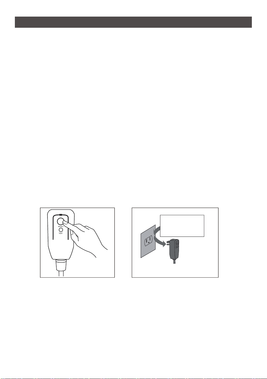
Opera�on of Current Device
The power supply cord contains a current measuring device that detects damage to the
power cord. Test your power supply cord as follows:
1. Plug in the air condi�oner.
2. The power supply cord will have TWO bu�ons on the plug head. Press the TEST bu�on.
You will no�ce a click as the RESET bu�on pops out.
3. Press the RESET Bu�on. You will no�ce a click as the bu�on engages.
4. The power supply cord is now supplying electricity to the unit.
(On some products this is also indicated by a light on the plug head.)
NOTE:
1. The power supply cord with this air condi�oner contains a current detec�on device
designed to reduce the risk of fire.
2. In the event that the power supply cord is damaged, it can not be repaired. It must be
replaced with a cord from the manufacturer.
3. Do not use this device to turn the unit on or off.
4. Always make sure the RESET bu�on is pushed in for correct opera�on.
5. The power supply cord must be replaced if it fails to reset when either the TEST bu
�on
is
pushed, or it can not be reset. Please contact Customer Service.
Plug in & press RESET
Grounding type wall receptacle
Do not, under any
circumstances, cut,
remove or bypass
the grounding prong.
Power supply cord with 3-prong grounding
plug and current detec�on device.
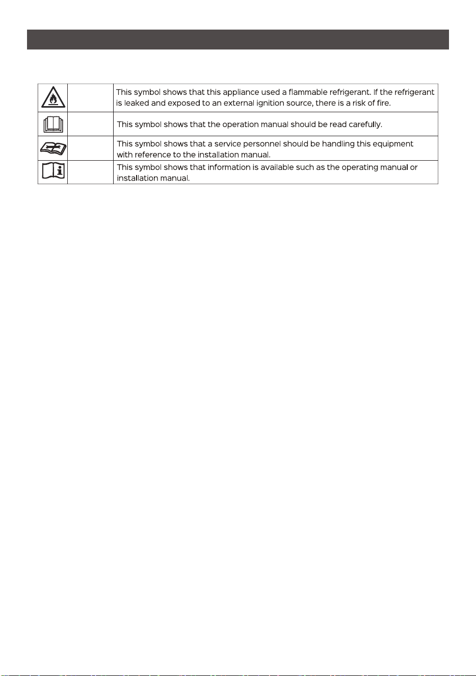
WARNING FOR USING R32 REFRIGERANT
4
IMPORTANT SAFETY INSTRUCTIONS
For R32 refrigerant models:
1. Appliance shall be installed, operated and stored in a room with a floor area larger
2
than 4 m .
2
2. Appliance shall not be installed in an unver�lated space, if that space is smaller than 4 m .
3. Compliance with na�onal gas regula�ons shall be observed.
4. Keep ven�la�on openings clear of obstruc�on.
5. The appliance shall be stored so as to prevent mechanical damage from occurring.
6. A warning that the appliance shall be stored in a well-ven�lated area where the room size
corresponds to the room area as specified for opera�on.
7. Any person who is involved with working on or breaking into a refrigerant circuit should
hold a current valid cer�ficate from an industry-accredited assessment authority, which
authorises their competence to handle refrigerants safely in accordance with an industry
recognised assessment specifica�on.
8. Servicing shall only be performed as recommended by the equipment manufacturer.
Maintenance and repair requiring the assistance of other skilled personnel shall be carried
out under the supervision of the person competent in the use of flammable refrigerants.
9. Please follow the instruc�on carefully to handle, install, clear, service the air condi�oner
to avoid any damage or hazard. Flammable Refrigerant R32 is used within air condi�oner.
When maintaining or disposing the air condi�oner, the refrigerant (R32) shall be recovered
properly, shall not discharge to air directly.
10.No any open fire or device like switch which may generate spark/arcing shall be around
air condi�oner to avoid causing igni�on of the flammable refrigerant used.
11.Please follow the instruc�on carefully to store or maintain the air condi�oner to prevent
mechanical damage from occurring.
12.Flammable refrigerant -R32 is used in air condi�oner. Please follow the instruc�on
carefully to avoid any hazard.
13.For specific informa�on on the type of gas and the amount, please to the relevant label
on the unit itself.
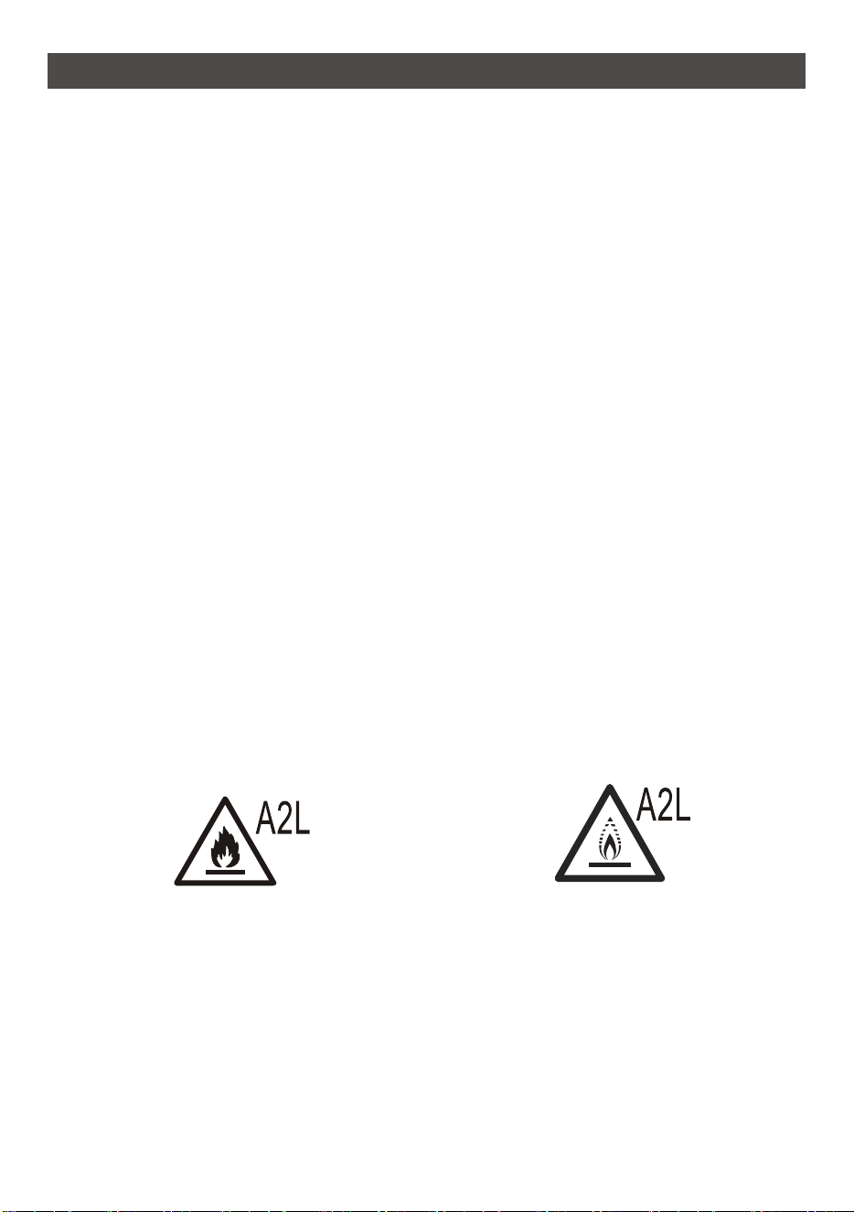
Cau�on: Risk of fire/flammable materials
(Required for R32 units only)
Warning: low burning velocity material
(For R32 models apply to IEC60335-2-40:2018)
Note about Fluorinated Gases
1. Fluorinated greenhouse gases are contained in herme�cally sealed equipment. For specific
informa�on on the type, the amount and the Co2 equivalent in tonnes of the fluorinated
greenhouse gas(on some models), please refer to the relevant label on the unit itself.
2. Installa�on, service, maintenance and repair of this unit must be performed by a cer�fied
technician.
3. Product uninstalla�on and recycling must be performed by a cer�fied technician.
5
IMPORTANT SAFETY INSTRUCTIONS
Explana�on of symbols displayed on the unit:
FOR HOUSEHOLD USE ONLY READ AND SAVE THESE INSTRUCTIONS
1. Transport of equipment containing flammable refrigerants
See transport regula�ons.
2. Marking of equipment using signs
See local regula�ons.
3. Disposal of equipment using flammable refrigerants
See na�onal regula�ons.
4. Storage of equipment/appliances
The storage of equipment should be in accordance with the manufacturer's instruc�ons.
5. Storage of packed (unsold) equipment
Storage package protec�on should be constructed such that mechanical damage to the
equipment inside the package will not cause a leak of the refrigerant charge. The maximum
number of pieces of equipment permi�ed to be stored together will be determined by
local regula�ons.
6. Informa�on on servicing
1) Checks to the area
Prior to beginning work on systems containing flammable refrigerants, safety checks are
necessary to ensure that the risk of igni�on is minimised. For repair to the refrigera�ng
system, the following precau�ons shall be complied with prior to conduc�ng work on the
system.
2) Work procedure
Work
shall be undertaken under a
controlled procedure so as to minimise the risk of a
flammable gas or vapour being present while the work is being performed.
3) General work area
All maintenance staff and others working in the local area shall be instructed on the
nature of work being carried out. Work in confined spaces shall be avoided. The area
around the workspace shall be sec�oned off. Ensure that the condi�ons within the area
have been made safe by control of flammable material.
4) Checking for presence of refrigerant
The area shall be checked with an appropriate refrigerant detector prior to and during
work, to ensure the technician is aware of poten�ally flammable atmospheres. Ensure
that the leak detec�on equipment being used is suitable for use with flammable
refrigerants, i.e. non-sparking, adequately sealed or intrinsically safe.
WARNING
CAUTION
CAUTION
CAUTION

IMPORTANT SAFETY INSTRUCTIONS
6
5) Presence of fire ex�nguisher
If any hot work is to be conducted on the refrigera�on equipment or any associated parts,
appropriate fire ex�nguishing equipment shall be available to hand. Have a dry powder or
CO2 fire ex�nguisher adjacent to the charging area.
6) No igni�on sources
No person carrying out work in rela�on to a refrigera�on system which involves exposing
any pipe work that contains or has contained flammable refrigerant shall use any sources
of igni�on in such a manner that it may lead to the risk of fire or explosion. All possible
igni�on sources, including cigare�e smoking, should be kept sufficiently far away from
the site of installa�on, repairing, removing and disposal, during which flammable
refrigerant can possibly be released to the surrounding space. Prior to work taking place,
the area around the equipment is to be surveyed to make sure that there are no flammable
hazards or igni�on risks. No Smoking signs shall be displayed.
7) Ven�lated area
Ensure that the area is in the open or that it is adequately ven�lated before breaking into
the system or
conduc�ng any hot work. A
degree of ven�la�on shall con�nue during the
period that the work is carried out. The ven�la�on should safely disperse any released
refrigerant and preferably expel it externally into the atmosphere.
8) Checks to the refrigera�on equipment
Where electrical components are being changed, they shall be fit for the purpose and to
the correct specifica�on. At all �mes the manufacturer's maintenance and service
guidelines shall be followed. If in doubt consult the manufacturer's technical department
for assistance. The following checks shall be applied to installa�ons using flammable
refrigerants:
a. The charge size is in accordance with the room size within which the refrigerant containing
parts are installed;
b. The ven�la�on machinery and outlets are opera�ng adequately and are not obstructed;
c. If an indirect refrigera�ng circuit is being used, the secondary circuit shall be checked for
the presence of refrigerant; Marking to the equipment con�nues to be visible and legible.
Markings and signs that are illegible shall be corrected;
d. Refrigera�on pipe or components are installed in a posi�on where they are unlikely to be
exposed to any substance
which may corrode
refrigerant containing components, unless
the components are constructed of materials which are inherently resistant to being
corroded or are suitably protected against being so corroded.
9) Checks to electrical devices
Repair and maintenance to electrical components shall include ini�al safety checks and
component inspec�on procedures. If a fault exists that could compromise safety, then no
electrical supply shall be connected to the circuit un�l it is sa�sfactorily dealt with. If the
fault cannot be corrected immediately but it is necessary to con�nue opera�on, an
adequate temporary solu�on shall be used. This shall be reported to the owner of the
equipment so all par�es are advised. Ini�al safety checks shall include:
a. That capacitors are discharged: this shall be done in a safe manner to avoid possibility of
sparking;
b. That there no live electrical components and wiring are exposed while charging,
recovering or purging the system;
c. That there is con�nuity of earth bonding.

IMPORTANT SAFETY INSTRUCTIONS
7
7. Repair to intrinsically safe components
Do not apply any permanent induc�ve or capacitance loads to the circuit without ensuring
that this will not exceed the permissible voltage and current permi�ed for the equipment
in use. Intrinsically safe components are the only types that can be worked on while live in
the presence of a flammable atmosphere. The test apparatus shall be at the correct ra�ng.
Replace components only with parts specified by the manufacturer. Other parts may result
in the igni�on of refrigerant in the atmosphere from a leak.
8. Cabling
Check that cabling will not be subject to wear, corrosion, excessive pressure, vibra�on,
sharp edges or any other adverse environmental effects. The check shall also take into
account the effects of aging or con�nual vibra�on from sources such as compressors or
fans.
9. Detec�on of flammable refrigerants
Under no circumstances shall poten�al sources of igni�on be used in the searching for or
detec�on of refrigerant leaks. A halide torch (or any other detector using a naked flame)
shall not be used.
10.Leak detec�on me
thods
The following leak detec�on methods are deemed acceptable for systems containing
flammable refrigerants. Electronic leak detectors shall be used to detect flammable
refrigerants, but the sensi�vity may not be adequate, or may need re-calibra�on.
(Detec�on equipment shall be calibrated in a refrigerant-free area.) Ensure that the
detector is not a poten�al source of igni�on and is suitable for the refrigerant used. Leak
detec�on equipment shall be set at a percentage of the LFL of the refrigerant and shall be
calibrated to the refrigerant employed and the app
ropriate
percentage of gas (25 %
maximum) is confirmed. Leak detec�on fluids are suitable for use with most refrigerants
but the use of detergents containing chlorine shall be avoided as the chlorine may react
with the refrigerant and corrode the copper pipe-work. If a leak is suspected, all naked
flames shall be removed/ex�nguished. If a leakage of refrigerant is found which requires
brazing, all of the refrigerant shall be recovered from the system, or isolated (by means
of shut off valves) in a part of the system remote from the leak. Oxygen free nitrogen
(OFN) shall then b
e
purged through the system both before and during the brazing process.
11.Removal and evacua�on
When breaking into the refrigerant circuit to make repairs or for any other purpose
conven�onal procedures shall be used. However, it is important that best prac�ce is
followed since flammability is a considera�on. The following procedure shall be adhered
to: Remove refrigerant; Purge the circuit with inert gas; Evacuate; Purge again with inert
gas; Open the circuit by cu�ng or brazing. The refrigerant charge shall be recovered into
the correct recovery cylinders. The system s
hal
l be flushed with OFN to render the unit safe.
This process may need to be repeated several �mes. Compressed air or oxygen shall not be
used for this task. Flushing shall be achieved by breaking the vacuum in the system with OFN
and con�nuing to fill un�l the working pressure is achieved, then ven�ng to atmosphere,
and finally pulling down to a vacuum. This process shall be repeated un�l no refrigerant is
within the system. When the final OFN charge is used, the system shall be vented down to
atmospheric pressure to enable work to take place. This opera�on is absolutely vital if
brazing opera�ons on the pipe-work are to take place
.
Ensure that the outlet for the
vacuum pump is not close to any igni�on sources and there is ven�la�on available.

IMPORTANT SAFETY INSTRUCTIONS
8
12.Charging procedures
In addi�on to conven�onal charging procedures, the following requirements shall be
followed. Ensure that contamina�on of different refrigerants does not occur when using
charging equipment. Hoses or lines shall be as short as possible to minimise the amount
of refrigerant contained in them. Cylinders shall be kept upright. Ensure that the
refrigera�on system is earthed prior to charging the system with refrigerant. Label the
system when charging is complete (if not already). Extreme care shall be taken not to
overfill the refrigera�on system. Prior to recharging the system it shall be pressure tested
with OFN. The system shall be leak tested on comple�on of charging but prior to
commissioning. A follow up leak test shall be carried out prior to leaving the site.
13.Decommissioning
Before carrying out this procedure, it is essen�al that the technician is completely familiar
with the equipment and all its detail. It is recommended good prac�ce that all refrigerants
are recovered safely. Prior to the task being carried out, an oil and refrigerant sample shall
be taken in case analysis is
required prior to re-use of
reclaimed refrigerant. It is essen�al
that electrical power is available before the task is commenced.
a.Become familiar with the equipment and its opera�on.
b.Isolate system electrically.
c.Before a�emp�ng the procedure ensure that: Mechanical handling equipment is available,
if required, for handling refrigerant cylinders; All personal protec�ve equipment is
available and being used correctly; The recovery process is supervised at all �mes by a
competent person; Recovery equipment and cylinders conform to the appropriate standards.
d. Pump down refrigerant system, if possible.
e. If a vacuum is not possible, make a manifold so that refrigerant can be removed from various
parts of the system.
f. Make sure that cylinder is situated on the scales before recovery takes place.
g. Start the recovery machine and operate in accordance with manufacturer's instruc�ons.
h. Do not overfill cylinders. (No more than 80 % volume liquid charge).
i. Do not exceed the maximum working pressure of the cylinder, even temporarily.
j. When the cylinders have been filled correctly and the process completed, make sure that the
cylinders and the
equipment are remove
d from site promptly and all isola�on valves on the
equipment are closed off.
K. Recovered refrigerant shall not be charged into another refrigera�on system unless it has
been cleaned and checked.
14.Labelling
Equipment shall be labelled sta�ng that it has been de-commissioned and emp�ed of
refrigerant. The label shall be dated and signed. Ensure that there are labels on the
equipment sta�ng the equipment contains flammable refrigerant.
15.Recovery
When removing refrigerant from a system, either for servicing or decommissioning, it is
recommended good prac�ce that all refrigerants are removed safely. When transferring
refrigerant into cylinders, ensure that only appropriate refrigerant recovery cylinders are
employed. Ensure that the correct number of cylinders for holding the total system charge
is available. All cylinders to be used are designated for the recovered refrigerant and
labelled for that refrigerant (i.e. special cylinders for the recovery of refrigerant).

9
IMPORTANT SAFETY INSTRUCTIONS
Cylinders shall be complete with pressure relief valve and associated shut-off valves in
good working order. Empty recovery cylinders are evacuated and, if possible, cooled
before recovery occurs. The recovery equipment shall be in good working order with a
set of instruc�ons concerning the equipment that is at hand and shall be suitable for the
recovery of flammable refrigerants. In addi�on, a set of calibrated weighing scales shall
be available and in good working order. Hoses shall be complete with leak-free disconnect
couplings and in good condi�on. Before using the recovery machine, check that it is in
sa�sfactory working order, has been properly maintained and that any associated
electrical components are sealed to prevent igni�on in the event of a refrigerant release.
Consult manufacturer if in doubt. The recovered refrigerant shall be returned to the
refrigerant supplier in the correct recovery cylinder, and the relevant Waste Transfer
Note arranged. Do not mix refrigerants in recovery units and especially not in cylinders.
If compressors or compressor oils are to be removed, ensure that they have been
evacuated to an
acceptable level to make certain that
flammable refrigerant does not
remain within the lubricant. The evacua�on process shall be carried out prior to
returning the compressor to the suppliers. Only electric hea�ng to the compressor body
shall be employed to accelerate this process. When oil is drained from a system, it shall be
carried out safely.
Gentle Reminder
Check the appliance regularly and refer to TROUBLESHOOTING or contact our customer
support if it shows any of the following signs:
- Power cord or plug is damaged.
- Loud noise, unusual smell or excessive heat.
10
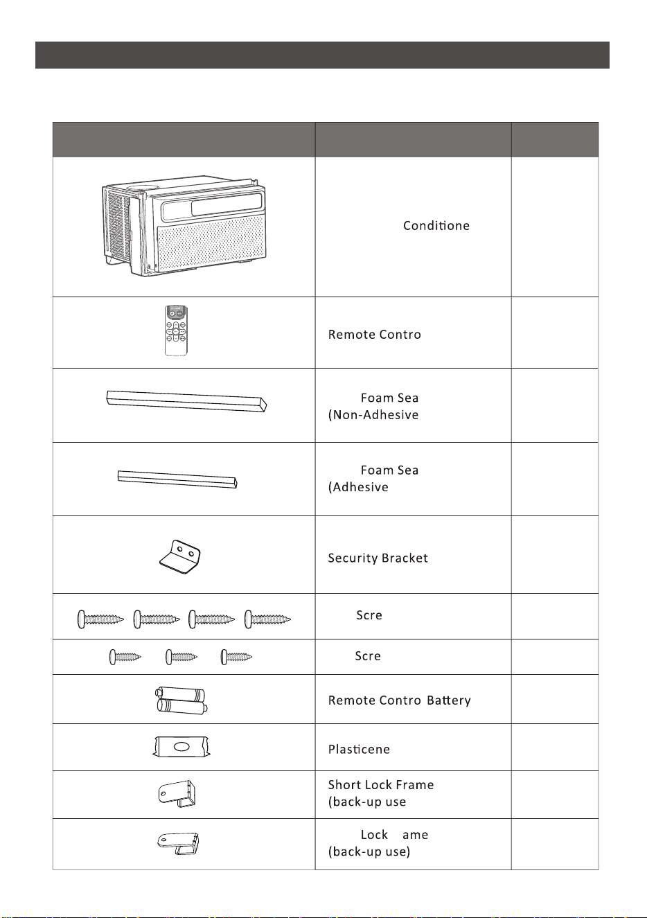
Part Name Quantity
Window Air r
l
Long
l
)
Long
l
)
3 w
"
1 / 2 w"
l
1
1
1
1
1
4
3
1
2
)
Long Fr
2
2
/4
ASSEMBLING YOUR AIR CONDITIONER
Package Contents
11
ASSEMBLING YOUR AIR CONDITIONER
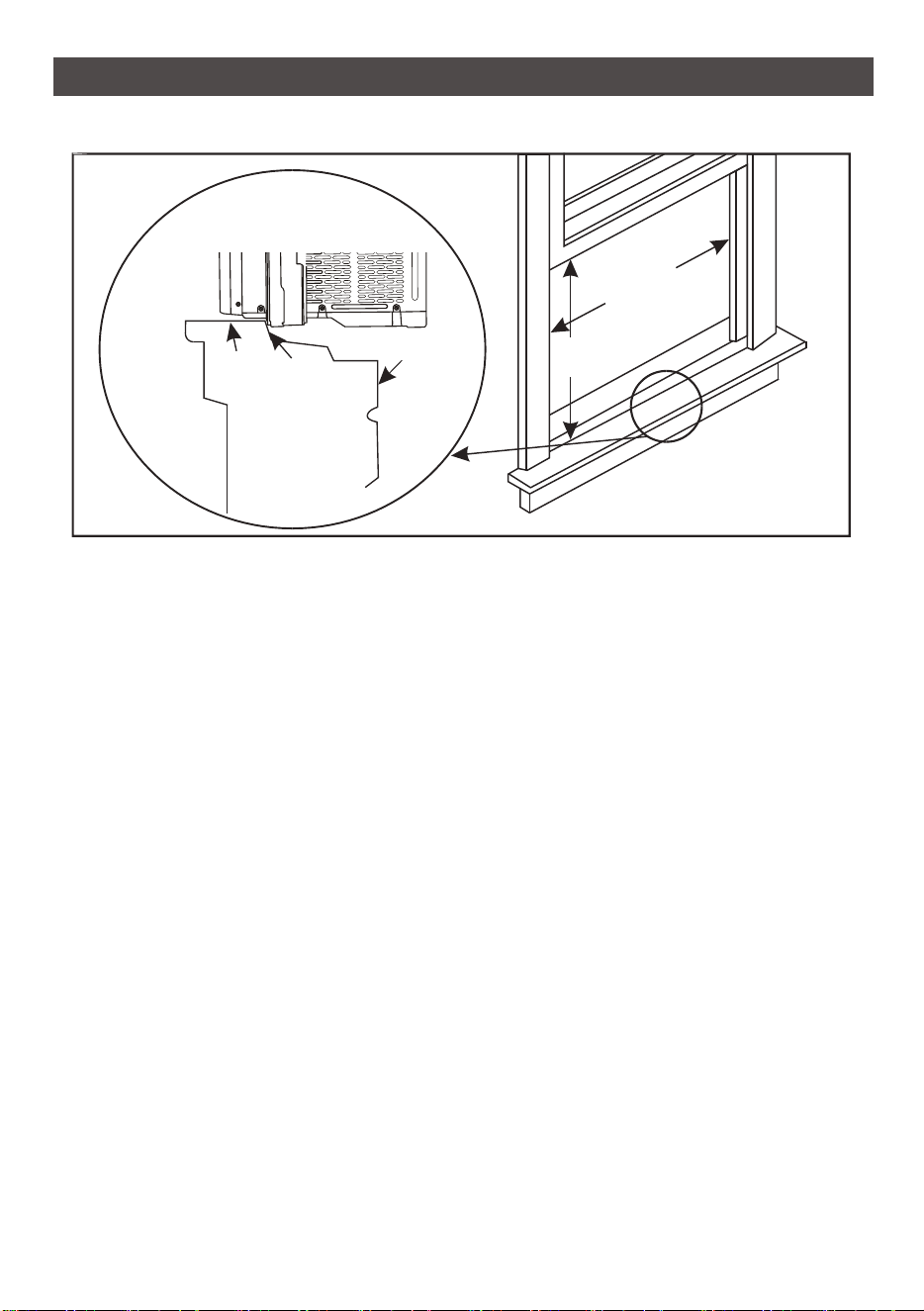
Window Requirements
1. This air condi�oner is designed to be installed in a standard single-hung or double-hung
window with a window width between 25" and 36"(645mm - 915mm).
2. The air condi�oner can be installed without the side panels to fit in a narrow window
opening. See the window dimensions. If the air condi�oner is installed on a window with
a width of 645-720mm, the air condi�oner must be installed to the right and the right
bracket must be abut on the air condi�oner, otherwise the air condi�oner will not
operate normally.
3. The lower sash (the lower part of the window that moves up and down) must allow for
14.5" of ver�cal clearance when open.
4. All suppor�ng parts must be secured to firm wood, masonry or metal.
5. The electrical outlet must be within reach of the power cord.
NOTE:
1. Save the product packaging and installa�on instruc�ons for future reference.
2. Store the air condi�oner in the product box during winter or when not in use.
Interior
Wall
Stool
Sill
Offset
Exterior
Wall
14.5 inch
368 mm
25-36 inch
645-915 mm
12
ASSEMBLING YOUR AIR CONDITIONER
Ge�ng Started
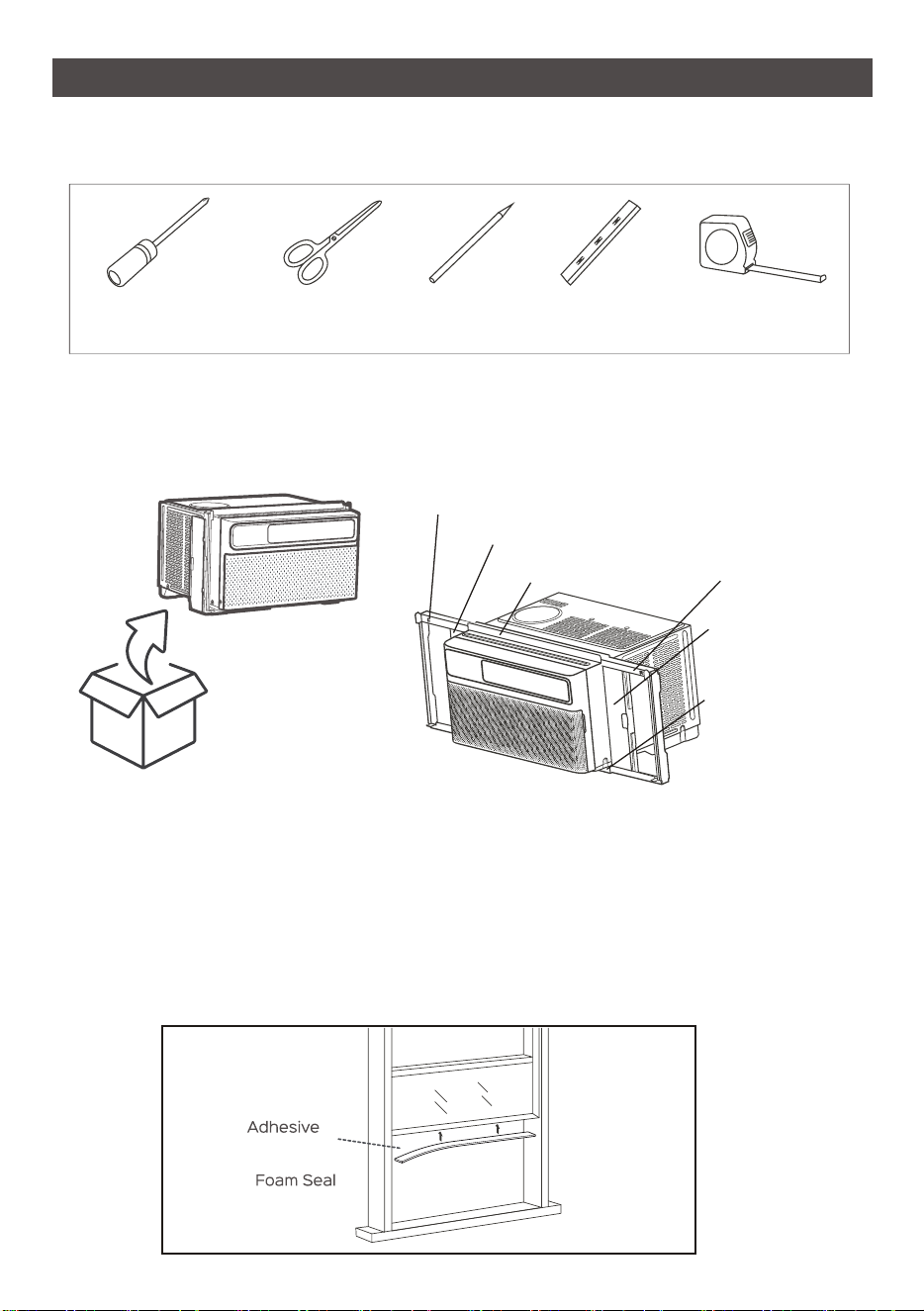
SUGGESTED TOOLS FOR INSTALLATION (Not included)
CAUTION:
Heavy object. Team handling is required during the installa�on process.
1. Removing All the Packaging
Carefully remove all the packaging straps and wraps from the air condi�oner and accessories.
CAUTION:
When handling the unit, be careful to avoid cuts from the sharp metal edges and aluminum
fins on the front and rear coils.
NOTE:
To be easy installa�on, both the le� and right curtains, curtain frames, top channel, and bo�om
channel, are pre-assembled in factory.
2.Applying the Adhesive Foam Seal
Measure the length of the upper window frame, trim the adhesive foam
seal to the appropriate length and apply as shown.
Phillips
screwdriver
Scissors
or knife
Pencil Level Ruler or
tape measure
Le� curtain frame,
pre-assembled in factory.
Le� curtain,
pre-assembled in factory.
Top channel,
pre-assembled in factory.
Right curtain frame,
pre-assembled in factory.
Right curtain,
pre-assembled in factory.
Bo�om channel,
pre-assembled in factory.
ASSEMBLING YOUR AIR CONDITIONER
13
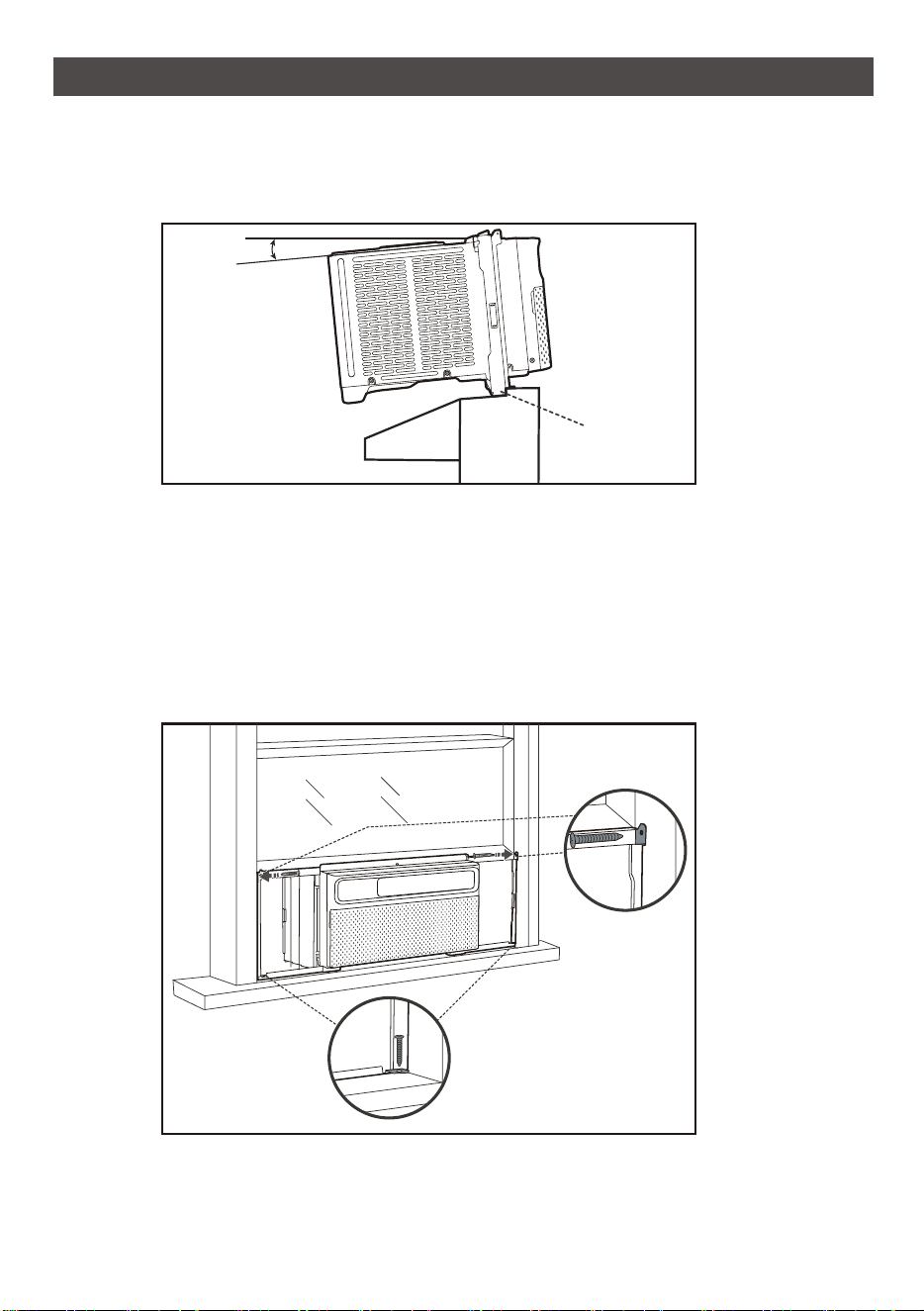
3.Placing Inside an Open Window
Carefully li� the air condi�oner with a helper to the windowsill and pull
down the sash, making sure the air condi�oner is centered and its bo�om
rail is flush against the windowsill.
NOTE:
o
The air condi�oner should be �lted about 3 for be�er drainage of condensate and
rainwater. Use a level: about 1/3 bubble willshow correct slant.
4.Securing the Side Brackets
Extend the side brackets from both sides of the air condi�oner onto the
le� and right window frames and secure by installing four 3/4" screws as
shown.
NOTE:
Fix the upper screws first, then the lower screws.
o
About 3
Outside Inside
Bo�om Rail
3 /4 Screws *4"
14
ASSEMBLING YOUR AIR CONDITIONER
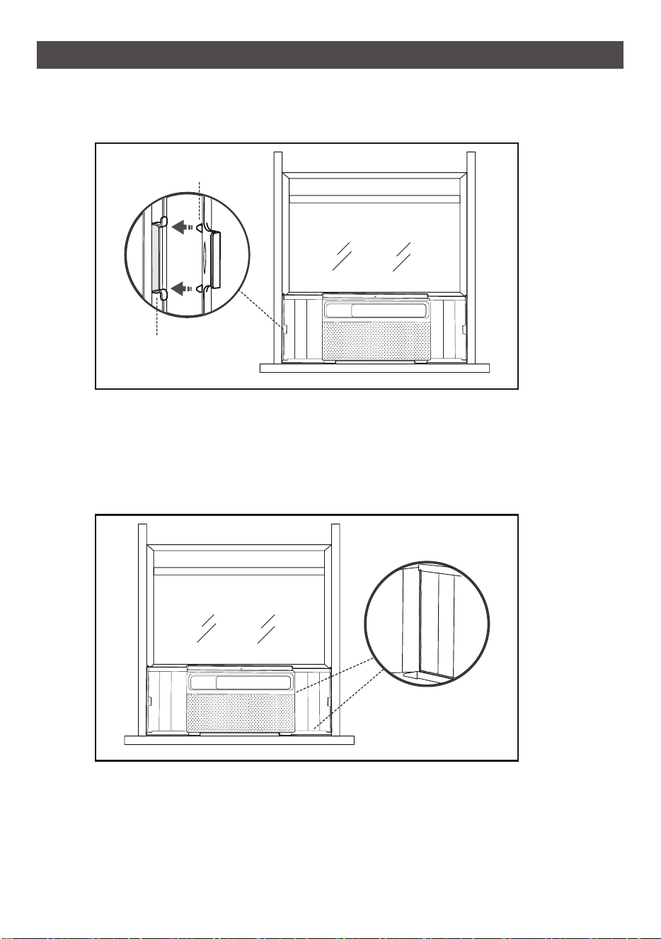
5.Securing the Side Panels
Pull the side panels inwards to align with the brackets, then secure onto
the sides by snapping the ju�ng points onto the locking pins.
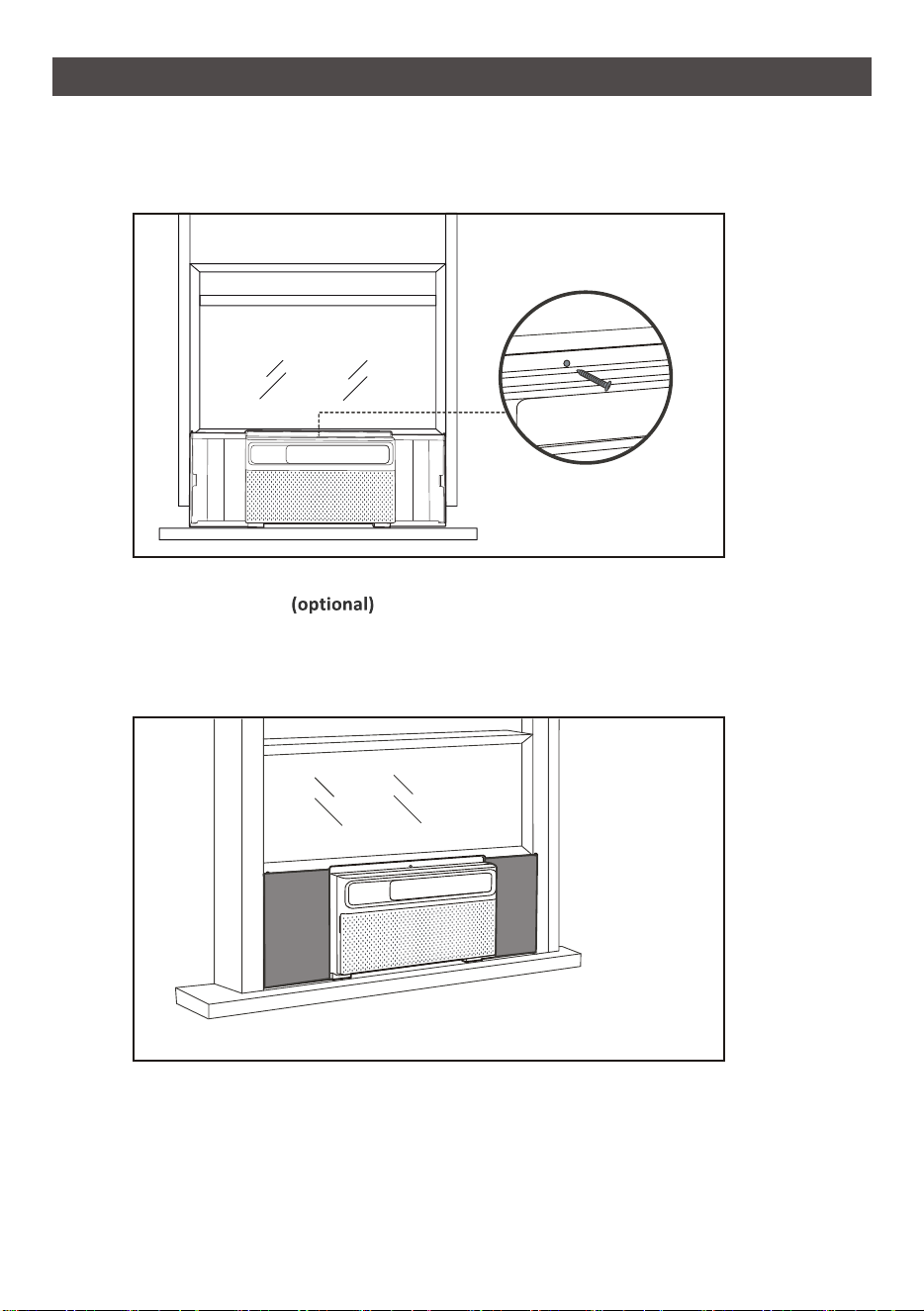
6.Sealing the Crevices with Plas�cene (Op�onal)
Fill the crevices between the side brackets and panels with the included
plas�cene.
Locking Pins
Ju�ng Points
15
ASSEMBLING YOUR AIR CONDITIONER
7.Installing the Screw Into the
Top Rail
Install the 1/ 2" screw into the top rail of the air condi�oner.
Note: It is recommended to install this screw and remove it only when you need to open the window
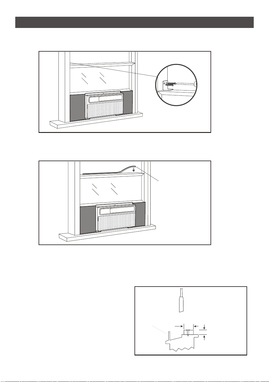
8.Applying the Panel Seals
Measure the length extended by the side panels, trim the panel seals to
the appropriate length, peel off the backings and apply on the panels on
both sides.
Top Rail
1 / 2 Screw *1"
Panel
Seals *2
16
ASSEMBLING YOUR AIR CONDITIONER
9.Installing the Security Bracket
A�ach the security bracket on top of the window sash and secure with two 1 / 2" screws.
10.Filling the Gap Between Sashes
Trim the non-adhesive foam seal to the appropriate length and insert
between the window sashes.
CAUTION:
When open the window, besure that the fixed screws are avaliable from the curtain to the
window frame.
If AC Is Blocked By Storm Window
1. Add wood as shown, or remove
storm window before air
condi�oner is installed.
2. If Storm Window Frame must
remain, be sure the drain holes
or slots are not caulked or
painted shut. Accumulated Rain
Water or Condensate must be
allowed to drain out.
1 / 2 Screw *2"
Non-Adhesive
Foam Seal
Storm window
frame or other
obstruc�on.
SASH
Board thickness as
required, for proper
pitch to rear, along
en�re sill. Fasten
with nails or screws.
OUTSIDE INSIDE
1-1/ 2 min
(38 mm)
"
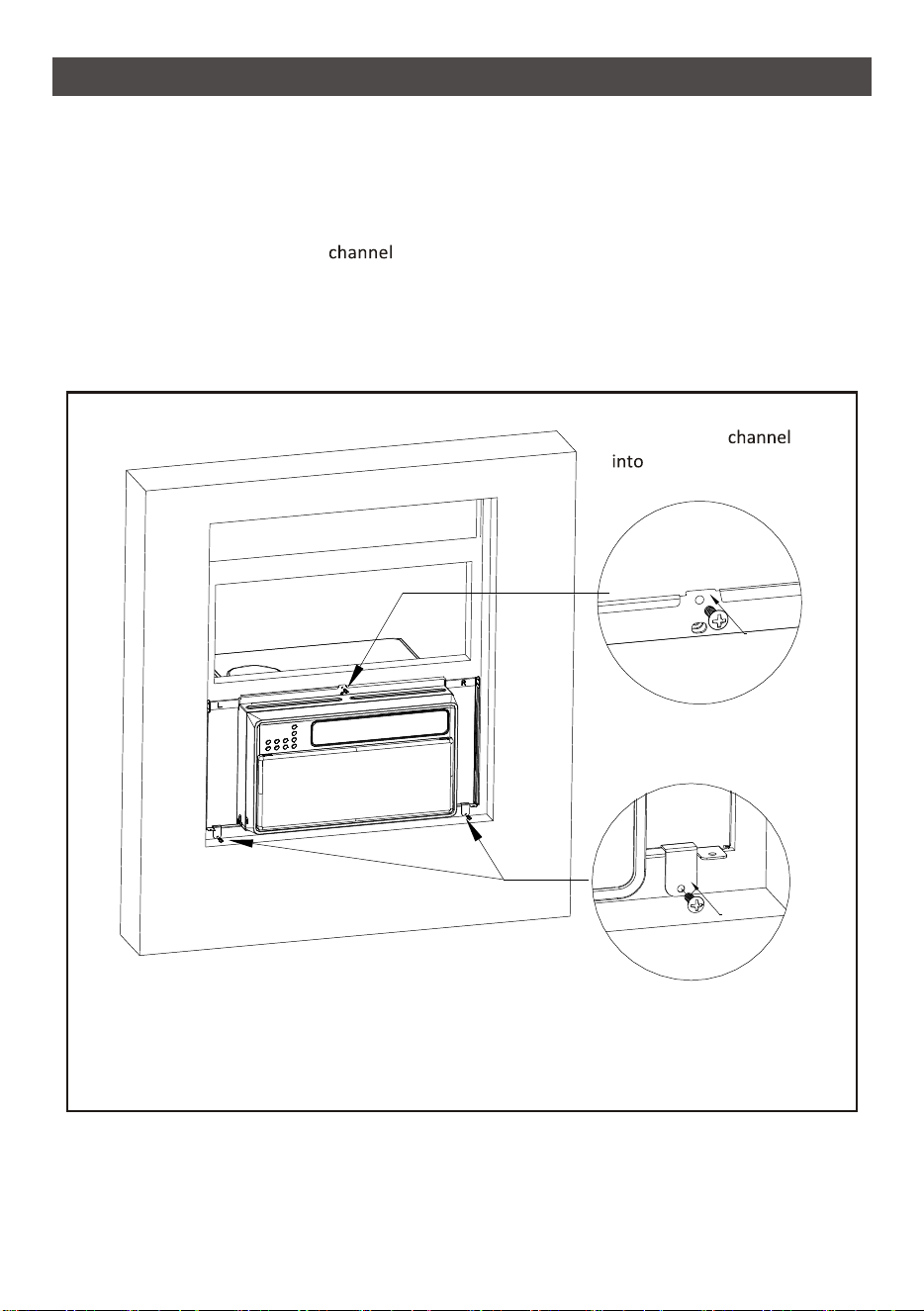
Screw the top
the window frame
with 3 /4 screw."
Screw the back-up lock
frame into the window
frame with 3 /4 screws,
both sides at the bo�om.
"
ASSEMBLING YOUR AIR CONDITIONER
For some special window frame, as too thin or too thick, you may need to use the back-up lock
frame to do the addi�onal fixed.
If the AC unit can not be screw-fixed well by the steel frame holes, you must use the back-up lock
frame to do the addi�onal fixed, as the aluminum alloy window.
1. Install the screw into the top
of the AC unit, and screw into the window frame.
2. Select two suitable back-up using lock frames, fix them at the bo�om of steel frame near the
sides with screws.
3. If needed, you can use the other two back-up using lock frames to do the addi�onal fix at the
top area.
17
ASSEMBLING YOUR AIR CONDITIONER
18
Installa�on & Assembly Instruc�ons
Important Considera�ons
1. Before installing the appliance, you must read the manual carefully to
get the safety informa�on and notes.
2. Unit refrigerant charge amount: refer to unit name plate marking.
3. A leak test must be done a�er the installa�on is completed.
4. It is a must to do the safety inspec�on before maintaining or repairing
an air condi�oner using combus�ble refrigerant in order to ensure
that the fire risk is reduced to minimum.
5. It is necessary to operate the machine under a controlled procedure
in order to ensure that any risk arising from the combus�ble gas or
vapor during the opera�on is reduced to minimum.
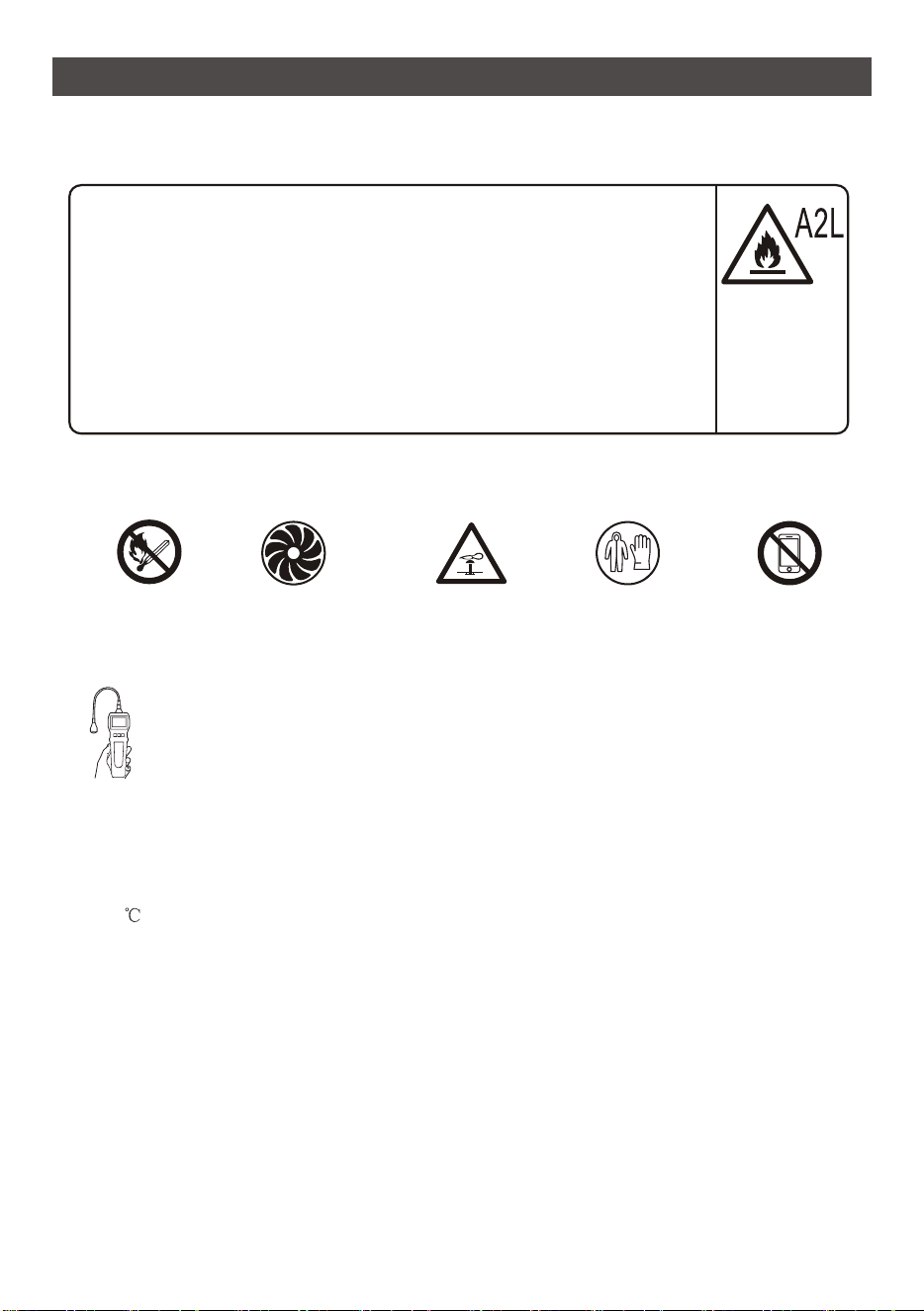
Introduc�on to Refrigerants R32
1.Site Safety 2.Opera�on Safety
3.Installa�on Safety
- Refrigerant Leak Detector
- Appropriate Installa�on Loca�on
- The le� picture is the schema�c diagram of arefrigerant leak detector.
Please note that:
1. The installa�on site should be in a well-ven�lated condi�on.
2. The sites for installing and maintaining an air condi�oner using Refrigerant R32 should be
free from open fire or welding, smoking, drying oven or any other heat source higher than
548 which easily produces open fire.
3. When installing an air condi�oner, it is necessary to take appropriate an�-sta�c measures
such as wear an�-sta�c clothing and/or gloves.
4. It is necessary to choose the site convenient for installa�on or maintenance wherein the air
inlets and outlets of the indoor and outdoor units should be not surrounded by obstacles
or close to any heat source or combus�ble and/or explosive environment.
5. If the indoor unit suffers refrigerant leak during the installa�on, all the personnel should go
out �ll the refrigerant leaks completely for 15 minutes. If the product is damaged, it is a
must to carry such damaged product back to the maintenance sta�on and it is prohibited to
weld the refrigerant pipe or conduct other opera�ons on the user's site.
6. It is necessary to
choose the
place where the inlet and outlet air of the indoor unit is even.
7. It is necessary to avoid the places where there are other electrical products, power switch
plugs and sockets, kitchen cabinet, bed, sofa and other valuables right under the lines on
two sides of the indoor unit, and also prevent mechanical damage from occurring.
Open Flames
Prohibited
Ven�la�on
Necessary
Mind Sta�c
Electricity
Must Wear
Protec�ve Clothing
and An�-Sta�c
Gloves
Don't Use
Mobile Phone
19
USING YOUR AIR CONDITIONER
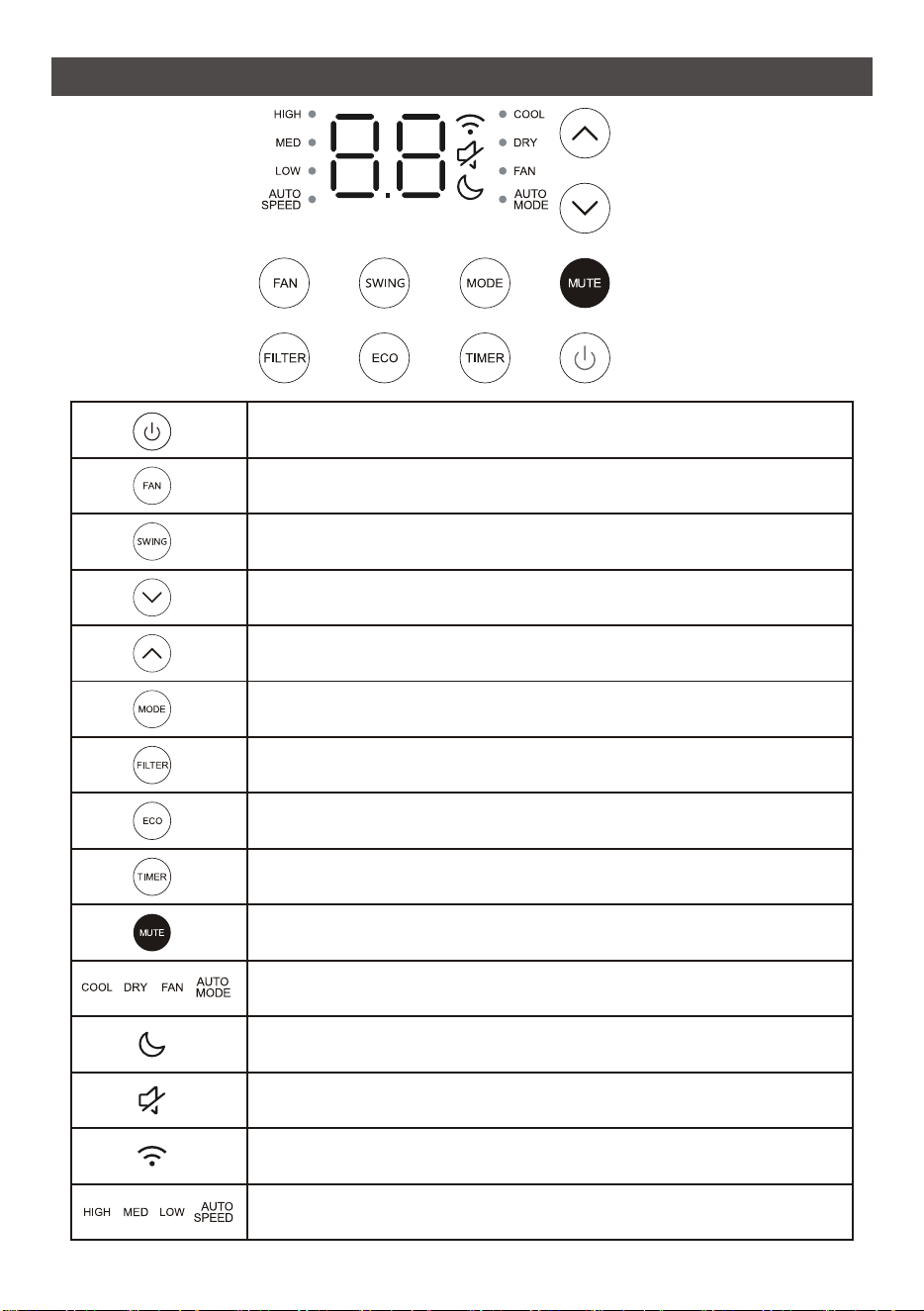
Turn on the air condi�oner or switch to standby.
Adjust fan speed (Low, Med, High, Auto)
NOTE: Fan speed se�ng is available in Auto,Cool, and Fan modes only.
Select to adjust the airflow direc�on by swinging the louver
ver�cally.
Decrease the air condi�oning temperature.
Increase the air condi�oning temperature.
Switch between Cool/Dry/Fan/Auto mode.
Remind to clean the dust filter.
Turn on/off the ECO mode, under Cool/Dry mode.
Timer on or Timer off the unit.
Turn on/off the MUTE mode.
Indicates Cool, Dry, Fan, and Auto mode, respec�vely.
Indicates the unit is in Sleep mode.
Indicates the unit is in MUTE mode.
Indicates that there is a WiFi connec�on
Indicates Low, Medium, High, and Automa�c fan speeds, respec�vely.
20
USING YOUR AIR CONDITIONER
General Opera�ons
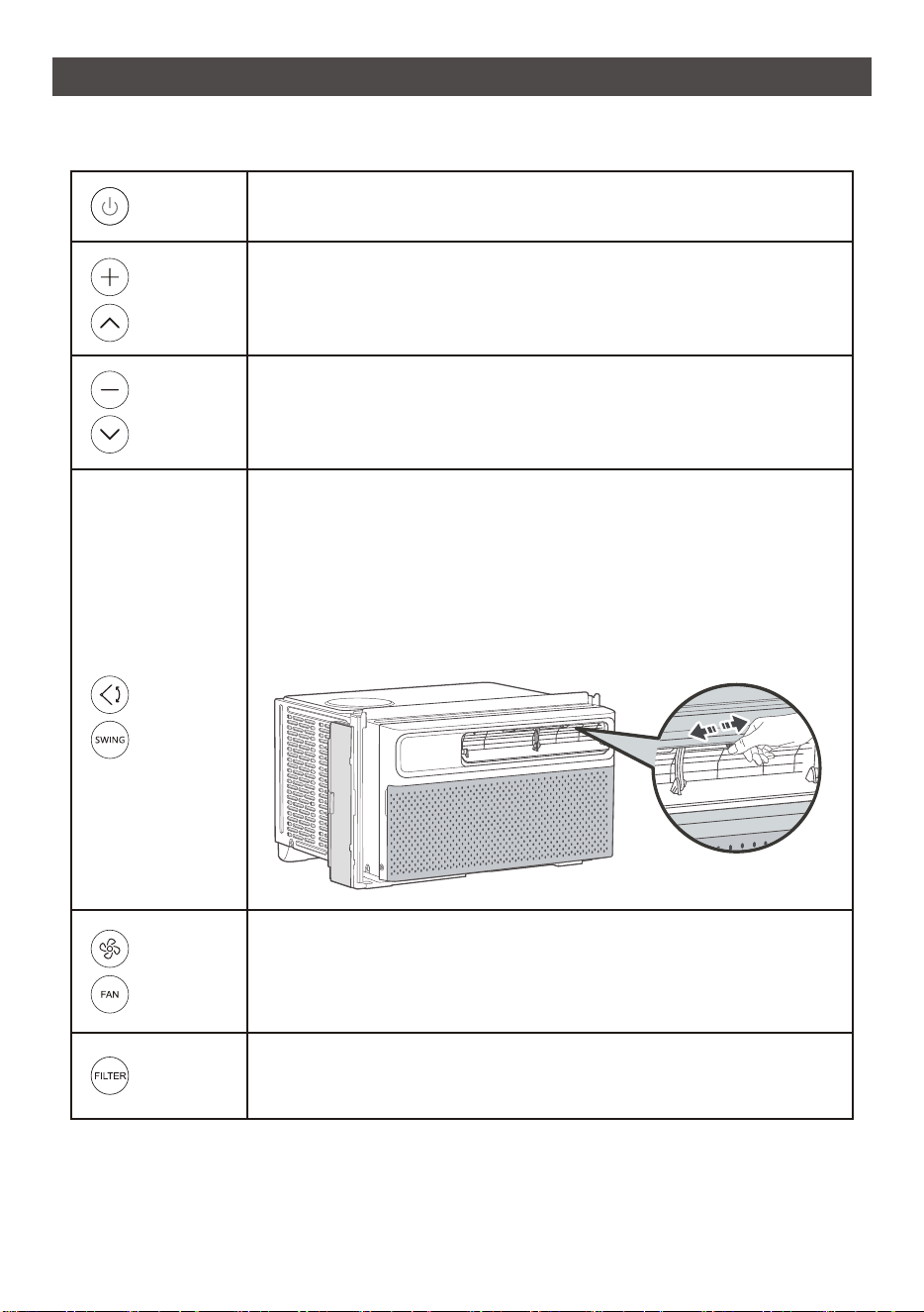
Press to turn on the air condi�oner or switch it to standby mode.
Press to increase the air condi�oning
o o
temperature by 1 F/ C.
1.Press to make the louver move up and down.
2.Press again to stop the louver at the desired angle.
NOTE: To adjust the airflow direc�on horizontally, manually move
the levers located on top of the air outlet from side to side.
NOTE: Do not adjust the big ver�al louver by hand, otherwise will
cause damage.
Power
Bu�o
n
Swing/
Oscilla�on
Bu�on
Decrease
Bu�on
Increase
Bu�on
Adjust Fan Speed
Press repeatedly to adjust fan speed: Low, Med, High, and Auto.
Press to decrease the air condi�oning
o o
temperature by 1 F/ C.
Fan Speed
Bu�on
NOTE:
- In Auto speed, fan speed will adapt to the room temperature.
- In Dry Mode, fan speed cannot be adjusted.
Reset Filter Reminder
To clean the filter, see page below.
Filter
Bu�on
21
USING YOUR AIR CONDITIONER
Press repeatedly to cycle through Cool, Dry, Fan and Auto modes.
Cool Mode
- In Cool mode, the air condi�oner cools the room to the desired
temperature.
- Temperature and fan speed are adjustable.
Dry Mode
- In Dry mode, the air condi�oner works as a dehumidifier to remove
humidity in the room. The fan is constantly running at a low speed.
- Temperature and fan speed cannot be adjusted.
Fan Mode
- In Fan mode, the air condi�oner circulates air like a normal fan.
Remember to open the vent during this func�on, but keep it closed
during cooling for maximum cooling efficiency.
- Fan speed can be set to Low, Med, or High.
- Temperature cannot be adjusted.
Auto Mode
- In Auto mode, the air condi�oner adjusts its working mode
(Cool or Fan) automa�cally based on the room temperature.
- Temperature and fan speed cannot be adjusted.
- When the air condi�oner is on standby/running, press the Timer
bu�on and its icon will flash on the remote display. During the
flashing process, press + or - to select a �mer from 0.5 to 24 hours,
then press the Timer bu�on again to confirm the se�ng. A�er the
�mer ends, the air condi�oner will start/stop running
automa�cally.
- Turning the air condi�oner ON or OFF at any �me or adjus�ng the
�mer se�ng to 0.0 hour will cancel the �mer program.
In Eco mode, when the desired temperature is reached, the
compressor will turn off and the fan will con�nue to run for
3 minutes. Then the fan cycles on for 1 minutes at 5 minute intervals
un�l the room temperature is above the set temperature, at which
�me the compressor turns back on and cooling restarts.
Mode
Bu�o
n
Timer
Bu�on
Eco Mode
Bu�on
Turn on/off Mute mode
Mute Mode
Bu�on
22
USING YOUR AIR CONDITIONER
1 r , Sleep mode ill e xit and the temperat re
ll ret rn to the tempera t re
NOTE: In Sleep mode, all the ill e m ted, and all the
Sleep mode indicator
Turn on or o the display on the air r .
Sleep
Mode
Bu�on (On
Remote
Control)
LED or
Display
Bu�on (On
Remote
Control)
Other Features
Filter Reminder
When the running �me of the fan reaches 500 hours, the filter reminder will light up to
remind you to clean the filter. To clean the filter, see page below.
Display Auto Off
- Display will dim a�er 30 seconds (off a�er 15 seconds in sleep mode).
- Wake up the display with any bu�on.
Memory
If the air condi�oner is turned OFF and stays connected to the power, it will operate under
the previous se�ngs (except the �mer se�ng) when it is turned ON again.
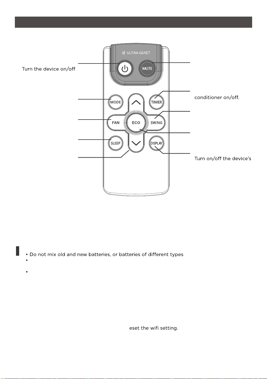
Drain Water
A�er proper installa�on, condens
te will not overflow during normal use.
If the fan hits the built-up water and the sound annoys you, please remove the cap located at
the back of the air condi�oner to drain the water away.
NOTE: Removing the cap may affect the heat transfer efficiency.
23
Remote Control
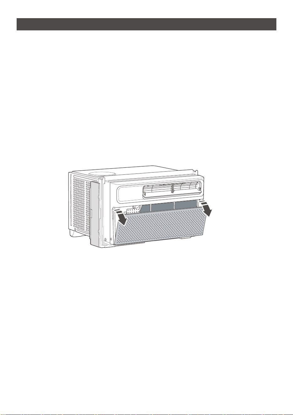
ECO MODE
Designed to save energy
while keeping your room
at the set temperature.
SWING
Start and pause vent
oscillation.
TIMER
Set a Timer to turn the air
MUTE
Select Mute to lower the
operating volume to its
quietest setting.
POWER
MODE
Cycle through Cool, Dry,
Fan, and Auto modes.
SLEEP MODE
Designed to save energy
while your sleep.
UP/DOWN
Increased or decrease the
temperature/Timer.
DISPLAY
display.
How to Control Your AC
FAN SPEED
Adjust the fan speed (Low,
Medium, High, Auto)
Press and hold f or 5s to
switch between
°F/°C.
For more information on how to use the remote and other functions of your air conditioning unit,
or to understand how each mode works, please refer to the next few pages.
Battery Replacement
The air conditioner comes with two batteries for the included remote control. Please be sure to
insert them correctly for proper use of the remote.
Tips for Using the Remote
1. The remote must be used within 26ft of the unit
2. The unit will make a sound when it receives the remote’s signal
3. Curtains, other materials, and even direct sunlight can interfere with the infrared signal
receiver.
4. Press “MODE” and “ ^” and hold for 3s to r
Note:
Do not leave batteries in the remote if you do not plan on using the device for more than 2
months
Follow your local city ordinances for information on proper disposal of old and used batteries.
Do not dispose of batteries in unsorted municipal waste.
24
CLEANING AND MAINTENANCE
Care and Cleaning
Clean your air condi�oner occasionally to keep it looking new. Be sure to unplug the unit
before cleaning to prevent shock or fire hazards.
Air Filter Cleaning
The air filter should be checked at least once every month to see if it needs cleaning.
o o
Never use hot water over 104 F (40 C) to clean the air filter. Never a�empt to operate the
unit without the air filter.
Trapped par�cles and dust can build up in the filter and may decrease airflow as well as
cause the cooling coils to accumulate frost. To clean the air filter:
1. Pull the grille out from the indents on both sides at the front and remove the filter inside.
2. Wash the filter using liquid dish soap and warm water. Rinse the filter thoroughly.
Gently shake the filter to remove
excess water.
3. Let the filter dry completely before placing it into the air condi�oner.
4. If you do not wish to wash the filter, you may vacuum the filter to remove the dust and
other par�cles.
Cabinet Cleaning
To clean the air condi�oner cabinet:
- Unplug the air condi�oner to prevent shock or a fire hazard. The cabinet and front panel
of the air condi�oner may be dusted with an oil free cloth or washed with a cloth dampened
in a solu�on of warm water and mild liquid soap. Rinse thoroughly with a damp cloth and
wipe dry.
- Never use harsh cleaners, wax or polish on the cabinet front.
- Be sure to wring excess water from the cloth before wiping around the controls. Excess
water in or around the controls may cause damage to the air condi�oner.
Winter Storage
To store the air condi�oner when it is not in use for an extended period of �me, remove it
carefully from the window according to the installa�on instruc�ons and cover it with plas�c
or place it in the original box.
25
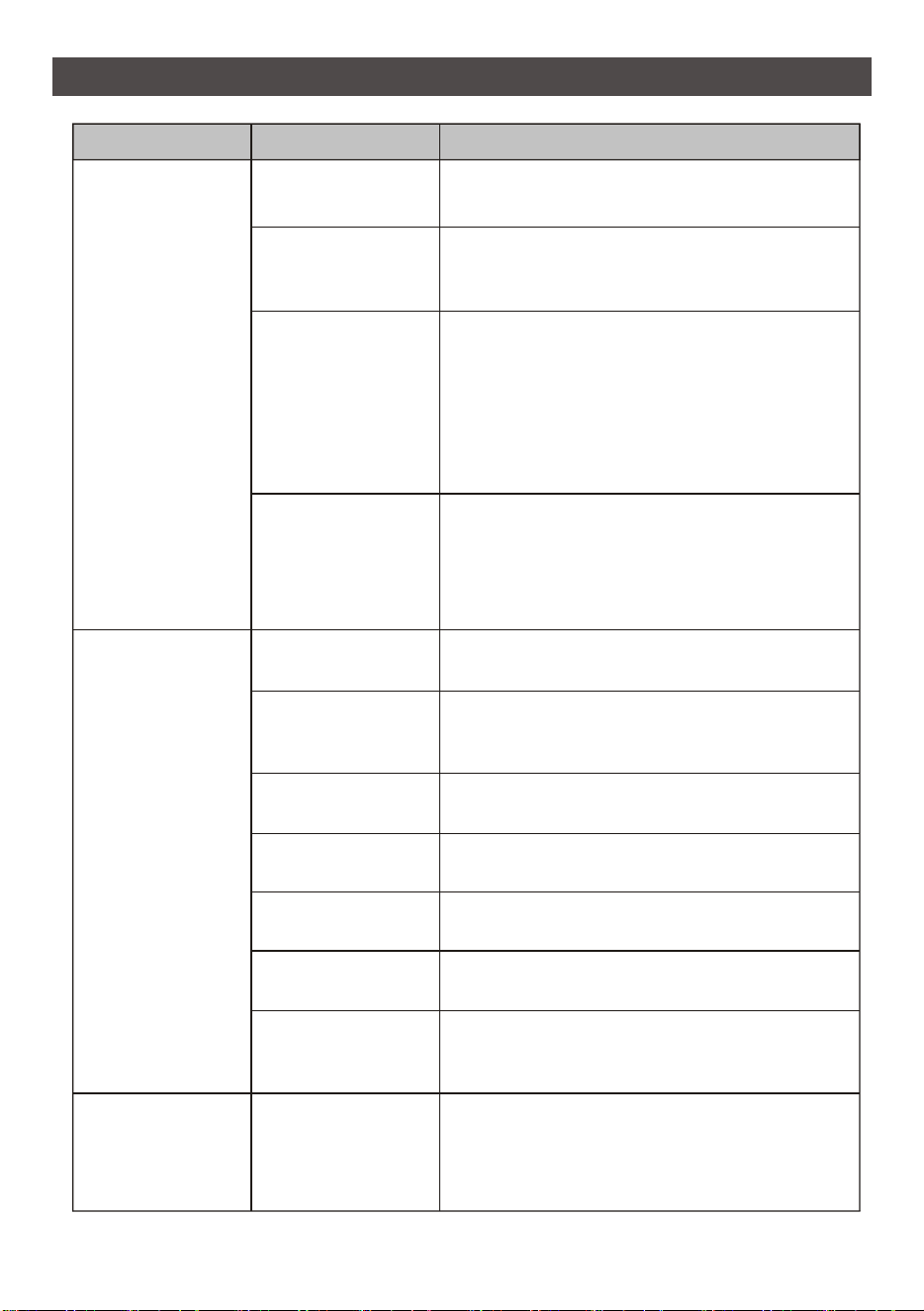
TROUBLESHOOTING
Possible Cause Solu�on
The air condi�oner
is unplugged
Make sure the air condi�oner plug is pushed
completely into the outlet.
The fuse is
blown/circuit
breaker is tripped
Check the house fuse/circuit breaker box and
replace the fuse or reset the breaker.
Power failure
- The unit will automa�cally restart when power
is restored.
- There is a protec�ve �me delay (approx.
3 minutes) to prevent tripping of the
compressor overload. For this reason, the unit
may not start normal cooling for 3 minutes
a�er it is turned back on.
The current
interrupter device
is tripped
- Press the RESET bu�on located on
the power
cord plug.
- If the RESET bu�on will not stay engaged,
discon�nue use of the air condi�oner and
contact a qualified service technician.
Air flow is restricted
Make sure there are no curtains, blinds or
furniture blocking the front of the air condi�oner.
The temperature
control may not be
set correctly.
Lower the set thermostat temperature.
The air filter is dirty
Clean the filter. Refer to
CLEANING & MAINTENANCE.
The room may be too
warm
Please allow �me for the room to cool down
a�er turning on the air condi�oner.
Cold air is escaping
Check for open furnace registers and cold air
returns.
The cooling
coil
s are
frozen
Switch to high fan speed and set the thermostat
to a higher temperature.
Temperature sensor
is not well situated.
Temperature sensor behind the air filter is
touching the coil.
Try to move it so it does not contact the cold coil.
Problem
The air condi�oner
will not start
The air condi�oner
does not cool as
it should
The air condi�oner
is freezing up
Ice blocks the air
flow and stops the
air condi�oner from
cooling the room
Switch to high fan speed and set the thermostat
to a higher temperature.
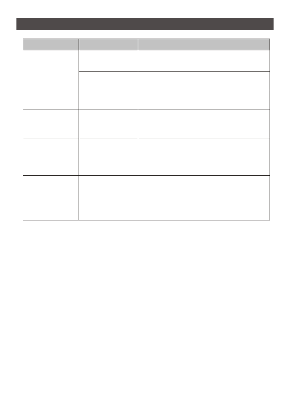
TROUBLESHOOTING
26
Possible Cause Solu�on
The ba�eries are
inserted incorrectly
Check the posi�on of the ba�eries.
The ba�eries may
be dead
Replace the ba�eries.
Hot and humid
weather
This is normal.
The air condi�oner is
not correctly �lted
outside
Improper installa�on. Tilt air condi�oner
slightly to the outside to allow water drainage.
Refer to installa�on instruc�ons.
Moisture removed
from the air is
draining into the
base pan
This is normal for a short period in areas with low
humidity and normal for a longer period in areas
with high humidity.
A "da-da" sound may
occur for 30 seconds
when the unit is
turned on due to the
compressor star�n
g.
Th
is is normal.
Problem
The remote
control is not
working
Water is dripping
INSIDE when the
unit is cooling
Noise when the
unit starts
Water is dripping
outside
Water is dripping
OUTSIDE when
the unit is cooling

CUSTOMER SUPPORT
Visit our website to contact us, find answers to Frequently Asked
Questions, and for other resources which may include an updated version of this user’s
manual
www.impecca.com
If you wish to contact us by phone, please be sure to have your model number and serial
number ready and call us between 9:00am and 6:00pm ET, at +1 866-954-4440
Keep tabs on Impecca’s newest innovations and enter contests via our social network
feeds:
www facebook com/Impecca/
www instagram com/impecca/
@impeccausa
27
ENGLISH
ONE-YEAR LIMITED APPLIANCE WARRANTY (US)
Impecca™ warrants this product against defects in material
and workmanship to the original purchaser as specified be-
low.
PARTS AND LABOR– if the product is determined to
have a manufacturing defect, within a period of one
year from the date of the original purchase, Impec-
ca™, at its own discretion, will repair or replace the
product parts at no charge to you in the U.S.A.
To obtain warranty service by an authorized Impecca™ ser-
vice center, please email us at: service@impecca.com to ob-
tain a Repair and Maintenance Authorization (RMA) number
and received instructions on how the repair and/or replace-
ment procedure will take place.
Any glass materials included with the appliance will
be covered for a period of 60 days from purchase.
Impecca™ specifically excludes from this warranty any
non-electric/mechanical attachments, accessories and
disposable parts including but not limited to outside case,
connecting cables, batteries and AC adapters. Impecca™ re-
serves the right to repair or replace defective products with
the same, equivalent or newer models.
We reserve the right to either repair or replace product at our
discretion. Replacement may be either new or refurbished
and while every endeavor will be made to ensure it is the
same model, if not possible it will be equal or higher spec-
ification.
Normal “Wear and Tear” is not covered by this warranty. Fur-
ther, Impecca™ hereby reserves the right to determine “Wear
and Tear” on any and all products. Tampering or opening the
product casting or shell will void this warranty in its entirety.
Exclusions: This warranty does not cover the following:
1. Any product that has a defaced or covered serial num-
ber.
2. Products that have been transferred to a second owner.
3. Rust on the interior or exterior of the unit.
4. Products listed as “As-Is” or “Refurbished.”
5. Food loss due to any product failure.
6. Window air conditioners installed in a wall.
7. The product if used in a commercial setting.
8. Service calls that do not involve product malfunction.
9. Service calls for a product ruined by not following the
provided instructions.
10. Service calls to correct improper installation.
11. Costs associated with making the product accessible
for servicing (including but not limited to removal of
trim/molding/cabinetry, etc.)
12. Service calls to replace any consumables such as light
bulbs, filters, etc.
13. Surcharges that may apply to service calls on weekends,
nights, holidays. Damages to the finish of appliance or
household furnishings due to installation of appliance.
14. Damages caused by any of the following: Acts of God;
fires; misuse; accidents; incorrect power supply; service
performed by unauthorized persons; use of non-genu-
ine Impecca parts, etc.
ALL IMPLIED WARRANTIES, INCLUDING IMPLIED WARRAN-
TIES OF MERCHANTABILITY AND FITNESS FOR A PARTICU-
LAR PURPOSE ARE LIMITED IN DURATION TO 1 YEAR FROM
THE DATE OF THE ORIGINAL RETAIL PURCHASE OF THIS
PRODUCT.
THESE WARRANTIES AND REMEDIES ARE THE SOLE AND
EXCLUSIVE WARRANTIES AND REMEDIES IN CONNECTION
WITH THE SALE AND USE OF THE PRODUCT. NO OTHER
WARRANTIES, ORAL OR WRITTEN, EXPRESSED OR IMPLIED,
ARE GIVEN.
IMPECCA™ IS NOT RESPONSIBLE OR LIABLE FOR ANY DAM-
AGE, WHETHER SPECIAL, INCIDENTAL, CONSEQUENTIAL,
DIRECT OR OTHERWISE, OR WHETHER KNOWN OR SHOULD
HAVE BEEN KNOWN TO IMPECCA™, INCLUDING LOST PROF-
ITS, GOODWILL, AND PROPERTY AND PERSONAL INJURY RE-
SULTING FROM ANY BREACH OF WARRANTY, THE INABILITY
TO USE THE PRODUCT OR UNDER ANY LEGAL THEORY IN
CONTRACT OR TORT. IMPECCA LIABILITY IS LIMITED TO THE
ACTUAL PURCHASE PRICE PAID TO THE RETAIL SELLER OF
THE DEFECTIVE PRODUCT.
No Impecca™ dealer, agent or employee is authorized to
make any modification, extension, change or amendment to
this warranty without the written consent and authorization
from Impecca™.
Some states do not allow the exclusion or limitation of im-
plied warranties or liability for incidental or consequential
damages, or do not allow a limitation on how long an im-
plied warranty lasts, so the above limitations or exclusions
may not apply to you. This warranty gives you specific legal
rights, and you have other rights, which vary from state to
state.
Note: Our Warranty center services only to Continental U.S.A.
ONE-YEAR LIMITED APPLIANCE WARRANTY (US)
28
ENGLISH

This descrip�on is applied to Air Condi�oners with Wi-Fi func�on. Please read the manual carefully
before using the product and keep it for future reference.
IWA08-VSA26
IWA10-VSA26
IWA12-VSA26
IWA15-VSA26
IWA18-VSB27
IWA24-VSB27

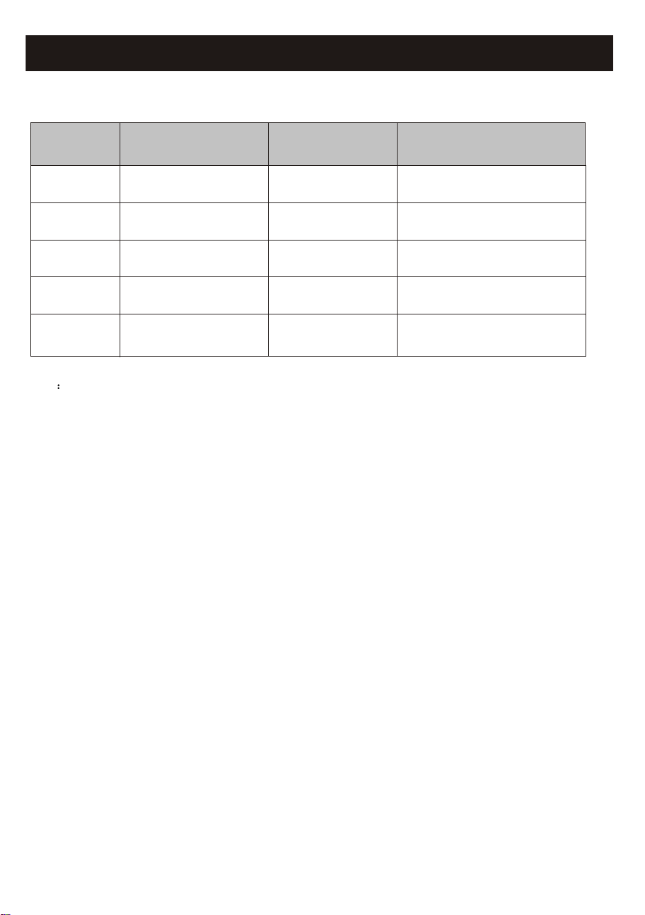
Step 3
Step 1
Operation
Steps
Step 4
Step 2
Step 5
Registration
Account
Download and
Install APP
Operation
Items
Login
Activate APP
Add Device to control
YES
YES
New Account
YES
YES
YES
NO
YES
Re-install APP
(registered before)
YES
YES
Registered Device will remain.
Operation guideline. Please take below simple guideline instruction as reference.
Note If you registered the account and added device before, when you re-install the APP again and login,
the added device will remain .
FCC Caution (FCC ID: 2AJCLTWAC-TYWFS/2ANDL-WBR3)
This device complies with part 15 of the FCC Rules. Operation is subject to the following two
conditions: (1) This device may not cause harmful interference, and (2) this device must accept
any interference received, including interference that may cause undesired operation.
Any Changes or modifications not expressly approved by the party responsible for compliance
could void the user's authority to operate the equipment.
Note: This equipment has been tested and found to comply with the limits for a Class B digital
device, pursuant to part 15 of the FCC Rules. These limits are designed to provide reasonable
protection against harmful interference in a residential installation. This equipment generates
uses and can radiate radio frequency energy and, if not installed and used in accordance with
the instructions, may cause harmful interference to radio communications. However, there is
no guarantee that interference will not occur in a particular installation. If this equipment does
cause harmful interference to radio or television reception, which can be determined by turning
the equipment off and on, the user is encouraged to try to correct the interference by one or
more of the following measures:
-Reorient or relocate the receiving antenna.
-Increase the separation between the equipment and receiver.
-Connect the equipment into an outlet on a circuit different from that to which the receiver is
connected.
-Consult the dealer or an experienced radio/TV technician for help.
The distance between user and device should be no less than 20cm.
Let's get start!

CONTENTS
Wi-Fi Module specification and basic information ..............................................1
Download and Install the App.............................................................................2
Activate APP.........................................................................................................3
Registration.........................................................................................................4
Login....................................................................................................................6
Add device........................................................................................................8
Air conditioner control.......................................................................................10
Account management........................................................................................28
Trouble Shooting...............................................................................30
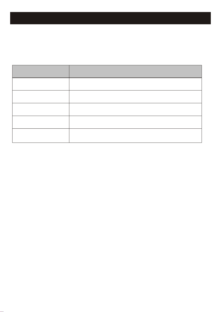
1. Minimum specifications on a Smart phone:
Android 5.0 version or higher
IOS 9.0 version or higher
Wi-Fi Module specification and basic information
1
2. Basic parameters for Wi-Fi module
2.400 - 2.500GHz
Protocol stack support
IEEE 802.11 b/g/n(channels 1-14)
Network frequency
Parameters
IPv4/IPv6/TCP/UDP/HTTPS/TLS/MulticastDNS
Security support
WEP/WPA/WPA2/AES128
Details
Standards of WLAN
Network type support
STA/AP/STA+AP
Download and Install the App
2
Note:
Please enable the permissions of Storage/Location/Camera for this APP when installing.
Otherwise it will have some problems when operating.
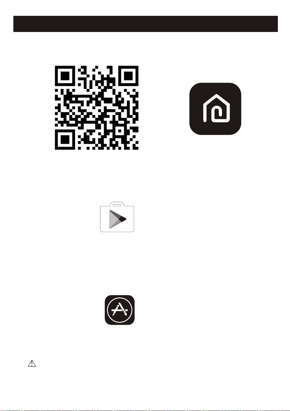
For Android smart phone
Method1: Please scan the QR code with a browser scanner, download and install the APP.
Method2: Open the Google "Play Store" on your smart phone and search
"SmartLife-SmartHome" , download and install the APP.
For IOS smart phone
Method1: Please scan the QR code and follow the tips to get into "AppStore", download
and install the APP.
Method2: Open the Apple "AppStore" on your smart phone and search
"SmartLife-SmartHome" , download and install the APP.
SmartLife-SmartHome
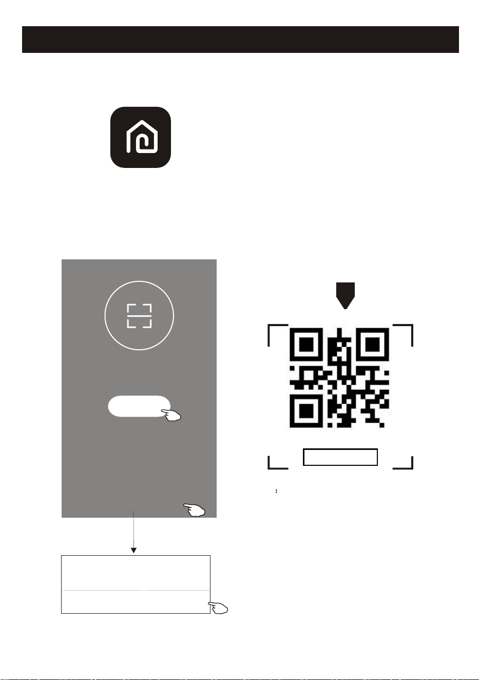
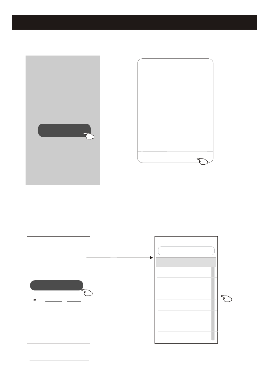
1. Launch the APP "SmartLife-SmartHome" on your smart phone.
3
Activate APP
2. Method1:Tap button "Scan" and scan the right Activate QR code
Method2: Tap "or Enter Activation Code" in bottom of the screen,
then enter the activate code 'IMPECCA' and tap "CONFIRM".
SmartLife-SmartHome
Activate QR code and activation code
Note Without the QR code or activation code,
you can't active the APP and using it,
please keep them safe.
Scan
Scan the activation QR code
from instructions or device
or Enter Activation Code
or Enter Activation Code
CANCEL
CONFIRM
******
The first time the app is used, it will need activating.
OR
IMPECCA
Registration
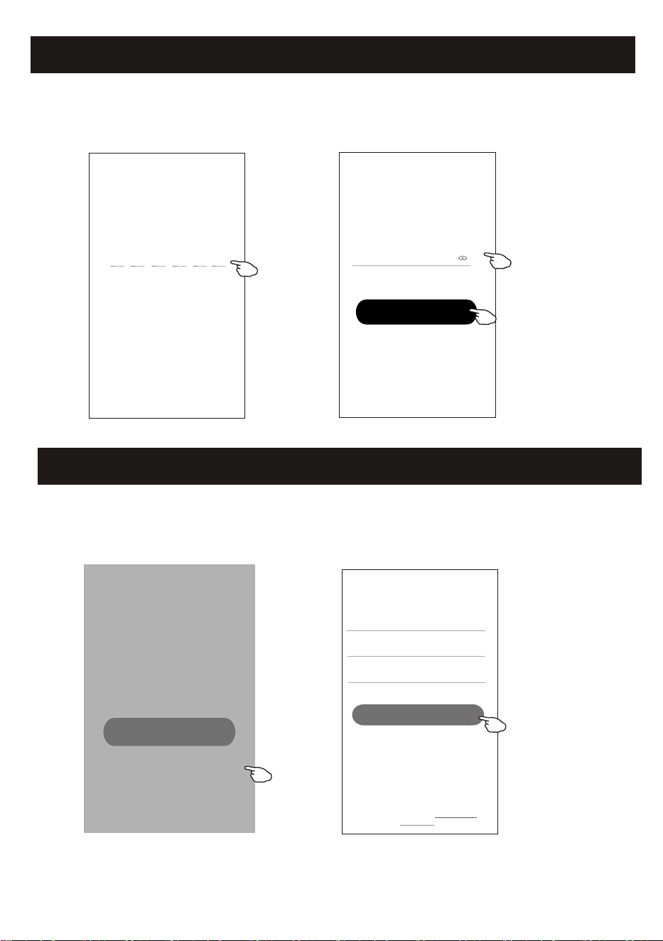
1.If you don't have any account please tap button "Register".
2.Read the Privacy Policy and tap "Agree".
4
3.Tap">" and choose the country.
4.Enter your e-mail address.
5.Tap the button "Obtain verification code".
Log in with existing account
Privacy Policy
......................................................
......................................................
......................................................
......................................................
......................................................
......................................................
......................................................
......................................................
......................................................
..................................................
Privacy Policy
Disagree
Agree
#
A
B
C
D
E
F
G
H
I
J
K
L
M
N
O
P
Q
R
S
T
U
V
W
X
Y
Z
Country Choosed
A
Afghanistan
Albania
Algeria
Angola
Argentina
Armenia
Australia
Search
enter your e-mail address here
Search the country or slide the
screen up/down to find
and choose the Country.
<
Register
Resister
>
*********** X
<
I Agree User agreement and Privacy Policy
Obtain verification code
Registration
6.Enter the verification code you received from e-mail.
7.Set the Password with 6-20 characters including characters and numbers.
8.Tap "Done".
5
Set Password
6-20 characters for password, including character, numbers
******
<
Login
Login
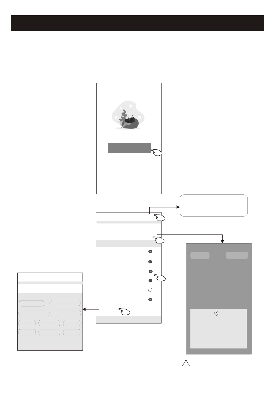
1.Tap "Log in with existing account".
2.Enter your registered account and password.
3.Tap "Log in" button.
Log in with existing account
Register
Done
Enter verification
code
* * * * * *
<
Verification code is sent to your email:
*****@****,Resend(55s)
Login
******* >
***********
<
Login means that you agree with User Agreement and
Privacy Policy
Log in
******
Forgot password
enter the password
enter your account(e-mail) here
Living Room
Master Bedroom
Second Bedroom
Dining Room
Kitchen Study Room Porch
Balcony Kids Room Closet
Login
The first time the APP is used, Create family is needed:
4.Tap "Create family".
5.Make name for the family.
6.Set the location.
7.Choose default rooms or add new rooms.
8.Tap "Done" and "Completed".
Turn on your smart life
Create family
Log out
#
A
B
C
D
E
F
G
H
I
J
K
L
M
N
O
P
Q
R
S
T
U
V
W
X
Y
Z
Family Name
<
Add family
Done
Family Location Set location >
Smart devices in rooms:
Living Room
Master Bedroom
Second Bedroom
Dining Room
Kitchen
Study Room
Add Room
You can change the room settings anytime
My home
choose the recommended room
or make a new room, then tap
Done.
Room Name
<
Add Room
Done
Recommended
*******
6
#
A
B
C
D
E
F
G
H
I
J
K
L
M
N
O
P
Q
R
S
T
U
V
W
X
Y
Z
Allow Smart Life to access this device's
location?
ALLOW ONLY WHILE IN USE
ALLOW ALL THE TIME
DENY
CANCEL
CONFIRM
Note:
The app can open the map on your
phone and you can set the location
where you are.
Family created successfully
View family Completed
Login
7
Forgot the password
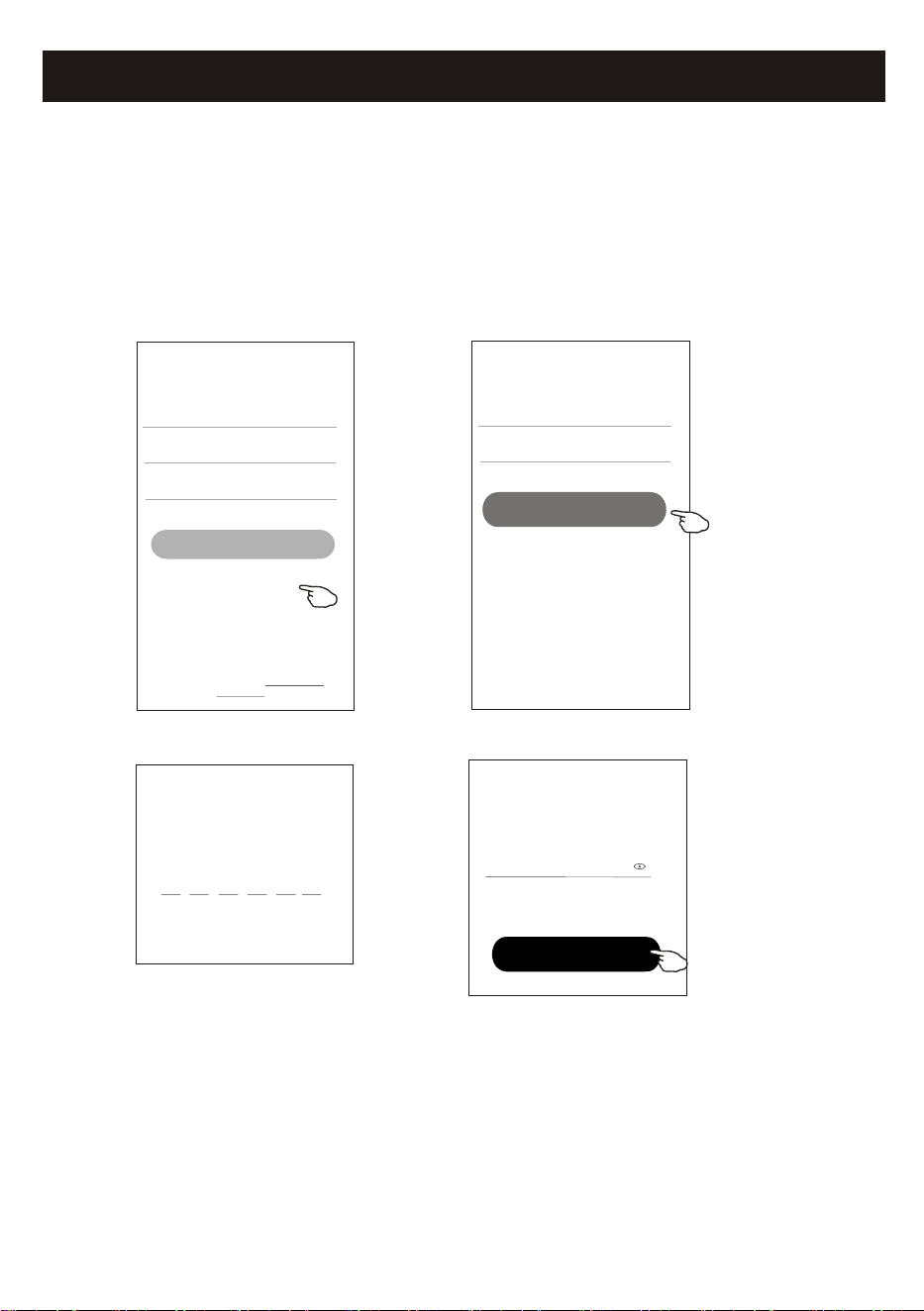
If you forgot the password or you want to reset the password, operate as below:
1.Tap "Forgot password".
2.Enter your account(e-mail address) and tap button "Obtain verification code".
3.Enter the verification code received by your e-mail.
4.Set the new password and tap button "Done".
Login
******* >
Email address
<
Log in
Password
Forgot password
Forgot password
****** >
*********** X
<
Obtain verification code
Enter verification
code
Verification code is sent to your email:
***********,Resend(55s)
* * * * * *
<
Set Password
6-20 characters for password, including character, numbers
******
<
Done
Login means that you agree with User Agreement and
Privacy Policy
8
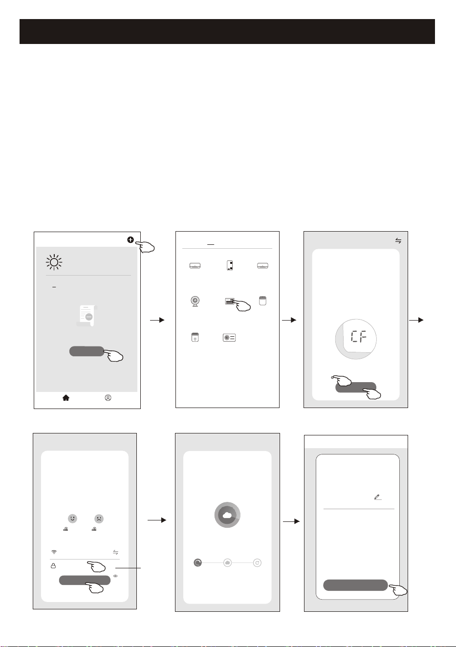
1.Power on the indoor unit, no need to launch the air conditioner.
2.Click "+" in the upper right corner of the "Home" screen or tap "Add device" on the room which has
no device.
3.Tap the "Window Type Air conditioner" logo.
4.Input the password of the Wi-Fi which the same as your smart phone connected, then tap "Next".
5.Choose "CF Mode" on the right corner, then follow the instruction on page before or screen to reset
the Wi-Fi module, then tap "Next".
6.You can see the percent rate of connecting process, at the same time
PP","SA","AP" shining in turn on the indoor display.
"PP" means "Searching the router"
"SA" means "connected to the router"
"AP" means "connected to the server"
Add device
There are 2 modes CF(Quick connection) and AP(Access Point) for adding device.
CF mode
CF Mode
Reset the device first.
Next
Cancel
Confirm the device is reset.
Resetting Devices
<
Add Device
<
Device added
successfully
Sample1
Done
enter
password
<
Add Manually
Auto Scan
Dehumidifier
Air Conditioner
(BT+Wi-Fi)
Fresh Air
Purifier
Split Air
Conditioner
Window Type
Air Conditioner
Portable Air
Conditioner
Security
Camera
Swimming
Pool H/P
Adding device...
Cancel
Ensure that the device is powered on.
2%
Scan
devices.
Register on
Cloud.
Initialize the
devices.
<
Welcome Home
Set your home location for more
information
All Devices Living Room
Master
...
Add Device
Home Me
Work office
<
No devices
Select 2.4 Ghz
Wi-Fi Network and
enter password
Next
Cancel
2.4GHz 5GHz
*******
Password
9
Add device
Select 2.4 Ghz
Wi-Fi Network and
enter password
Next
Cancel
2.4GHz 5GHz
*******
Password
AP Mode
Reset the device first.
Next
Cancel
Confirm the device is reset.
Resetting Devices
<
AP Mode
Reset the device first.
Method1:When there is a DISPLAY key on the
remote control, press the DISPLAY key 6 times
in the time of 8 seconds; when there is no
DISPLAY key on the remote control, press the
ECO key 6 times in the time of 8 seconds until
the device beeps twice and the LCD screen
show AP .
Next
Cancel
Confirm the device is reset.
Resetting Devices
<
Method2:Press the General key 9 times in the
time of 8 seconds until the device beeps twice
and the LCD screen show AP .
CF Mode
AP Mode
Default
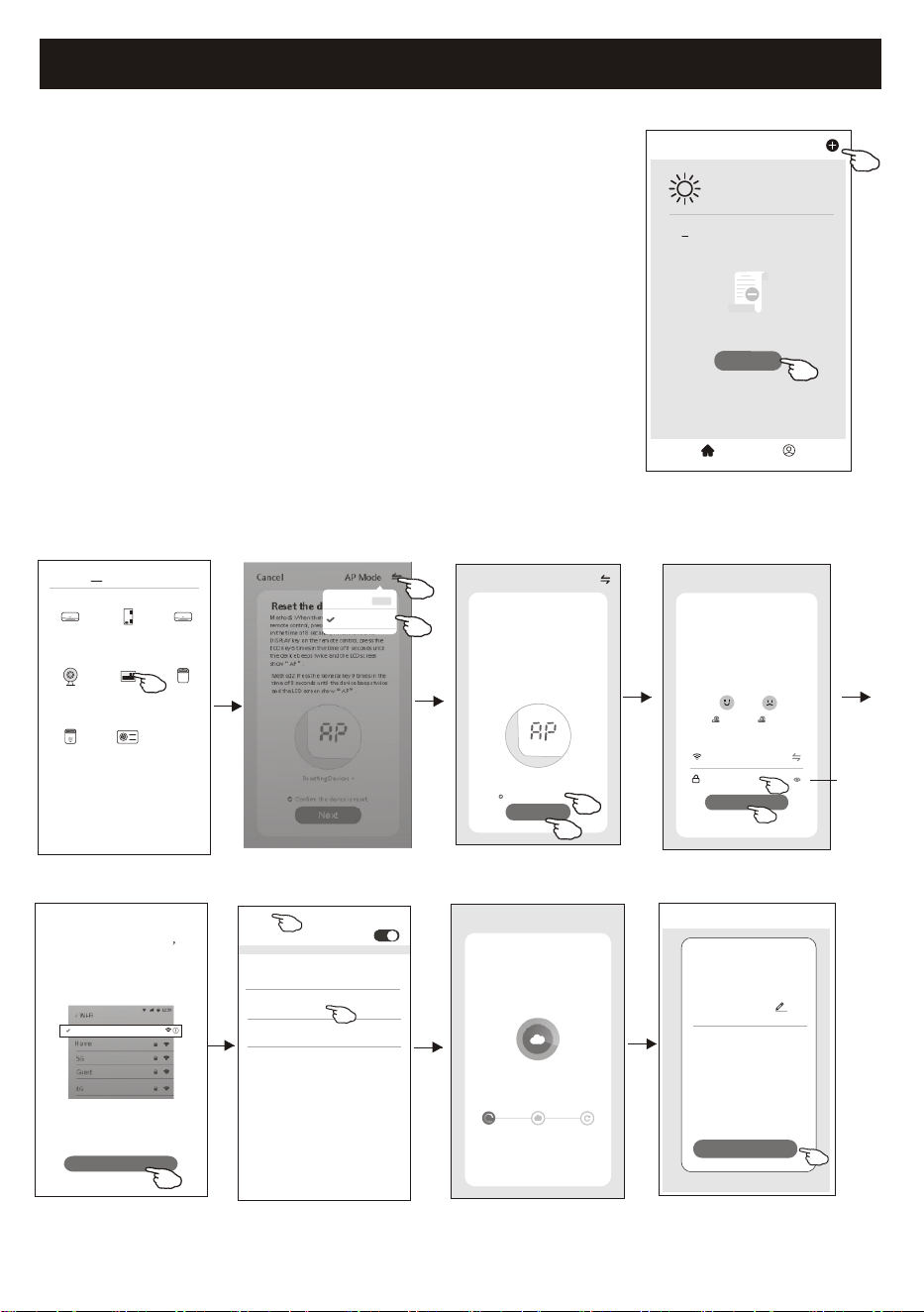
1.Power on the indoor unit, no need to launch the air conditioner.
2.Click "+" in the upper right corner of the "Home" screen
or tap "Add device" on the room which has no device.
3.Tap the "Window Type Air Conditioner" logo.
4.Input the password of the Wi-Fi which the same as your smart
phone connected, then tap "Next".
5.Choose "AP Mode" on the right corner, then follow the instruction on
page before or screen to reset the Wi-Fi module, then tap "Next".
6.Read the instruction carefully and tap "Connect now".
7.In the network setting screen, select "SmartLife-****", and tap" ".
8.You can see the percent rate of connecting process, at the same time
"PP","SA","AP" shining in turn on the indoor display.
"PP" means "Searching the router"
"SA" means "connected to the router"
"AP" means "connected to the server"
There are 2 methods to add the device.
2-AP mode
<
Add Manually
Auto Scan
Dehumidifier
Air Conditioner
(BT+Wi-Fi)
Fresh Air
Purifier
Split Air
Conditioner
Window Type
Air Conditioner
Portable Air
Conditioner
Security
Camera
Swimming
Pool H/P
<
WLAN
AVAILABLE NETWORKS
SmartLife-****
office wifi
WIFI1
<
Add Device
<
Device added
successfully
Sample1
Done
<
Welcome Home
Set your home location for more
information
All Devices Living Room
Master
...
Add Device
Home Me
Work office
<
No devices
enter
password
<
Connect phone to device s
wifi hotspot
Connect now
1.Please connect your phone to the hotspot
shown below
Wi-Fi
Home
5G
Guest
4G
12:30
<
SmartLife-XXXX
2.Return to this app and continue adding
devices
Confirm hot spot connecton,next
Adding device...
Cancel
Ensure that the device is powered on.
2%
Scan
devices.
Register on
Cloud.
Initialize the
devices.
Air conditioner control
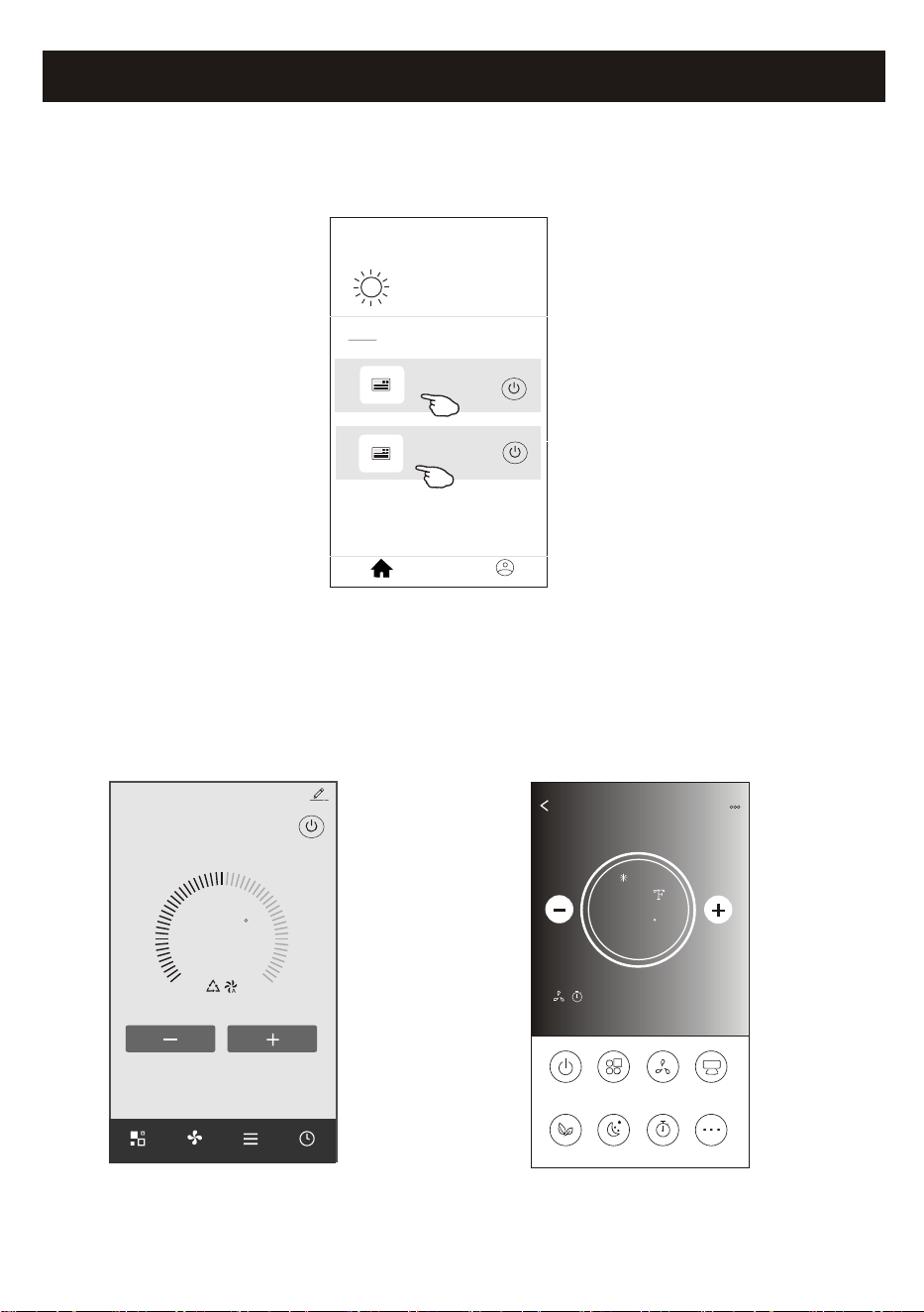
The device control screen will pop up automatically after adding the device.
The device control screen will pop up manually by tapping the device name on the home screen.
<<
my home
+
>
Set your home location, get more
information
Welcome home
V
All Devices
Living Room
room
Master Bed
...
Home
Me
Sample1
Sample2
Turned off
Already On
ON/OFF
Fan Speed
Precision
Air Flow
More
Eco Sleep
Mode
Timer
Sample1
77
Cool
0
Note:
There are two different control forms base on different software or Wi-Fi module firmware.
Please read the manual carefully base on the real control interface.
72
F
Set Temperature
Timer
Function
Fan
Mode
Sample2
<
10
Control form1
Control form2
11
Air conditioner control
72
F
Set Temperature
Timer
Function
Fan
Mode
Sample2
<
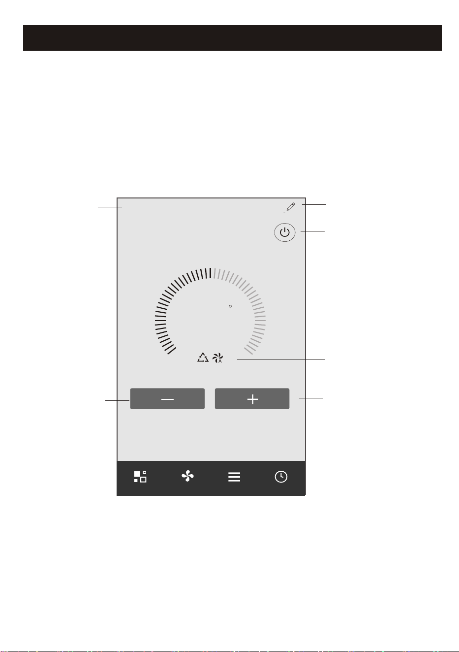
Turn ON/OFF the
air conditioner
Device details
and management
Increase the
setting temperature
Decrease the
setting temperature
The main control interface
Back to the
Home screen
Indicator of
setting temperature
Selected Mode/Fan speed/
Functions indicator
Control form1
Air conditioner control
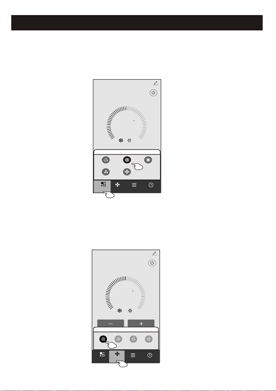
Control form1-Mode setting
1.Tap Mode to pop up the Mode screen.
2.Select one of the mode Feel/Cool/Heat/Dry/Fan.
3.Tap anywhere around the setting temperature to cancel the Mode setting.
72
F
Set Temperature
Timer
Function
Fan
Sample2
<
Mode
FanDry
Feel
Cool Heat
Mode
Control form1-Select fan speed
72
F
Set Temperature
Timer
Function
Sample2
<
Mode
Fan
Fan
Med Low Auto
High
1.Tap Fan to pop up the Fan screen.
2.Select one of the fan speed High/med/Low/Auto.
3.Tap anywhere around the setting temperature to cancel the selection.
12
Air conditioner control
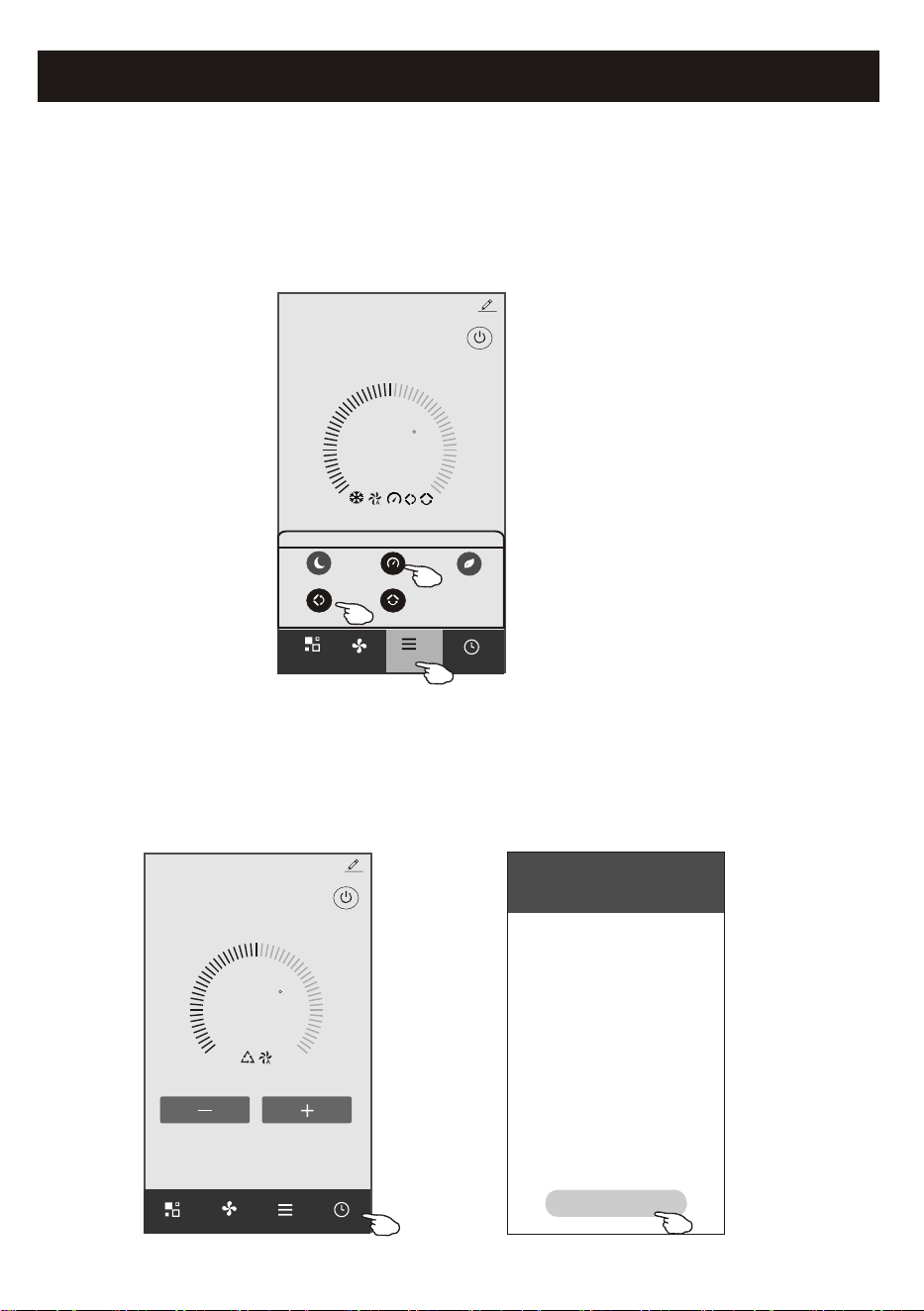
Control form1-Function setting
1.Tap Function to pop up the Function screen.
2.Select one of the functions Sleep/Turbo/ECO.
3.Select UP-DOWN/LEFT-RIGHT for auto swing with direction of UP-DOWN/LEFT-RIGHT.
4.Tap anywhere around the setting temperature to cancel the Function setting.
72
F
Set Temperature
Timer
Fan
Sample2
<
Mode
Control form1-Timer adding
1.Tap Timer to pop up the Add Timer screen.
2.Tap Add Timer.
13
Function
UP-DOWN
LEFT-RIGHT
Turbo
Sleep
ECO
Function
72
F
Set Temperature
Timer
Function
Fan
Mode
Sample2
<
WLAN
<
Add Timer
Add timer
Air conditioner control
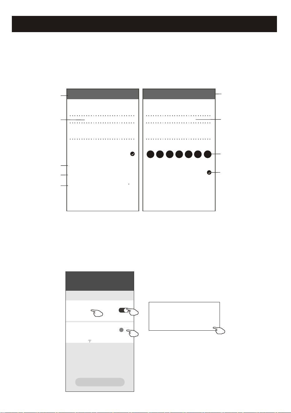
Control form1-Timer adding
3.Select the time, select the repeat days and Timer on/off.
4.Select the Mode/Fan speed/Function and select the setting temperature for Timer on.
5.Tap Save to add the timer.
14
Hour setting
Minute setting
Mode setting
Fan Speed
setting
Weekly setting
Timer cancel
Timer submit
Temperature
setting
Timer ON/OFF
setting
Cancel Add Timer Save
15 10
14 09
13 08
12 07
16 11
17 12
18 13
Timer Off
Timer On
Mode
Fan
Set Temperature
Function
Cool
Auto
72 F
<
<
<
<
Cancel Add Timer Save
15 28
14 27
13 26
12 25
16 29
17 30
18 31
Select days to use Smart Mode
Timer Off
Mon
Tues
Wed Thur Fri Sat Sun
Timer On
Control form1-Timer Management
WLAN
<
Add Timer
Add timer
Timer accuracy is -/+ 30 seconds
12:20
Once
Timer:Off
12:20
Mon, Tue, Wed, Thurs
Timer: On 61 Cool Turbo UP-DOWN
1.Tap the bar of timer to edit the Timer like the Timer adding process.
2.Click the switch to enable or disable the Timer.
3.Holdind the bar of Timer about 3seconds and pop up the Remove Timer screen,
tap CONFIRM and remove the Timer.
Remove Timer
Remove the timer?
CANCEL CONFIRM
Timer on
Timer off
Air conditioner control
15
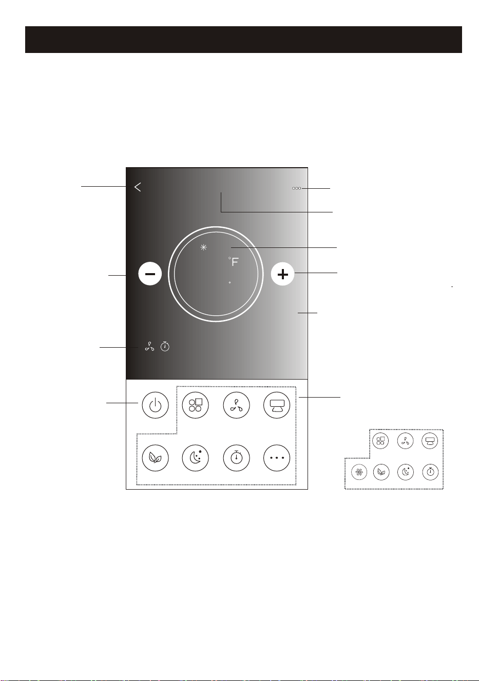
Back to the
Home screen
Name of the device
Current mode
Increase the
setting temperature
Decrease the
setting temperature
Power on/off
Selected Functions
indicator
Note: it may appear slightly different ,
depending on the air conditioner model.
Example as below:
Tips
Different background for
different mode:
Cool/Heat/Dry/Fan/Auto
ON/OFF
Fan Speed
Precision
Air Flow
More
Eco Sleep
Mode
Timer
Sample1
77
Cool
0
Fan Speed
Swing Flow
Eco Sleep
Mode
Timer
Turbo
Function Buttons
Control form2
The main control interface
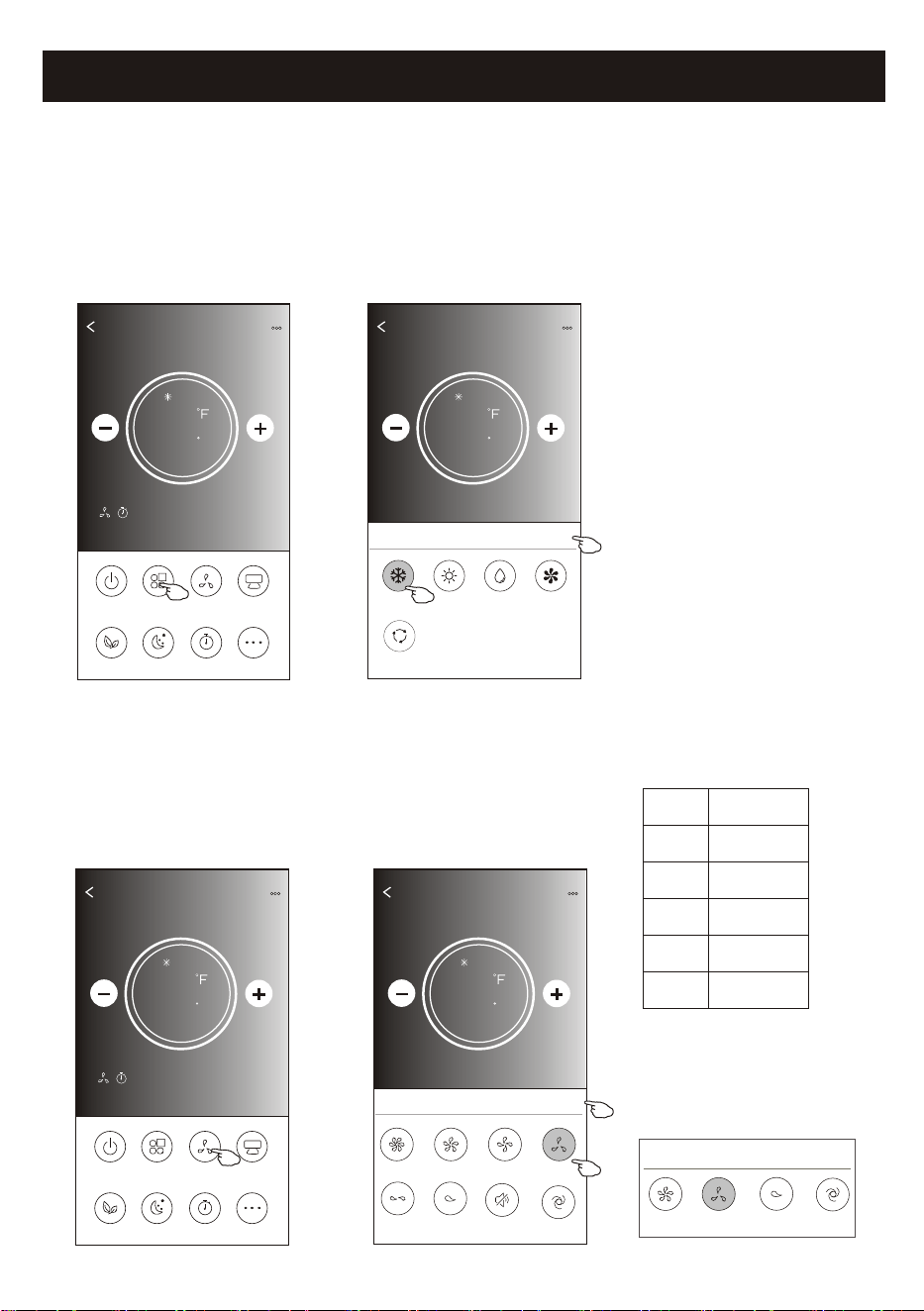
Air conditioner control
1.Tap the Mode button.
2. There are 5 modes on the Mode screen, tap one button to
set the Air conditioner working mode.
3.Tap the X button to back the main control screen.
4.The mode and background will change on the screen.
ON/OFF
Fan Speed
Precision
Air Flow
More
Eco Sleep
Mode
Timer
Sample1
77
Cool
0
Back
Sample1
77
Cool
0
Cool
Dry
Fan
Heat
Auto
Mode
X
Note: please read the details of each mode
in the user manual to control more comfortable.
ON/OFF
Fan Speed
Precision
Air Flow
More
Eco Sleep
Mode
Timer
Sample1
77
Cool
0
1.Tap the Fan speed button.
2.Choose your desired fan speed and tap it.
3.Tap the X button to back the main control screen.
4.The selected fan speed indicator will appear on the screen.
Back
Sample1
77
Cool
0
Turbo
Mid-High
Mid
high
Fan Speed
X
Mid-Low
Mute
Auto
Low
Mode Fan Speed
Cool
Fan
Dry
Heat
Auto
All speeds
All speeds
All speeds
All speeds
16
Note: Fan Speed screen may appear slightly different ,
depending on the air conditioner model.
Example as below:
Mid
high
Fan Speed
X
Auto
Low
Note:
Fan Speed can't be adjusted on Dry mode .
Control form2-Mode setting
Control form2-Fan speed selection
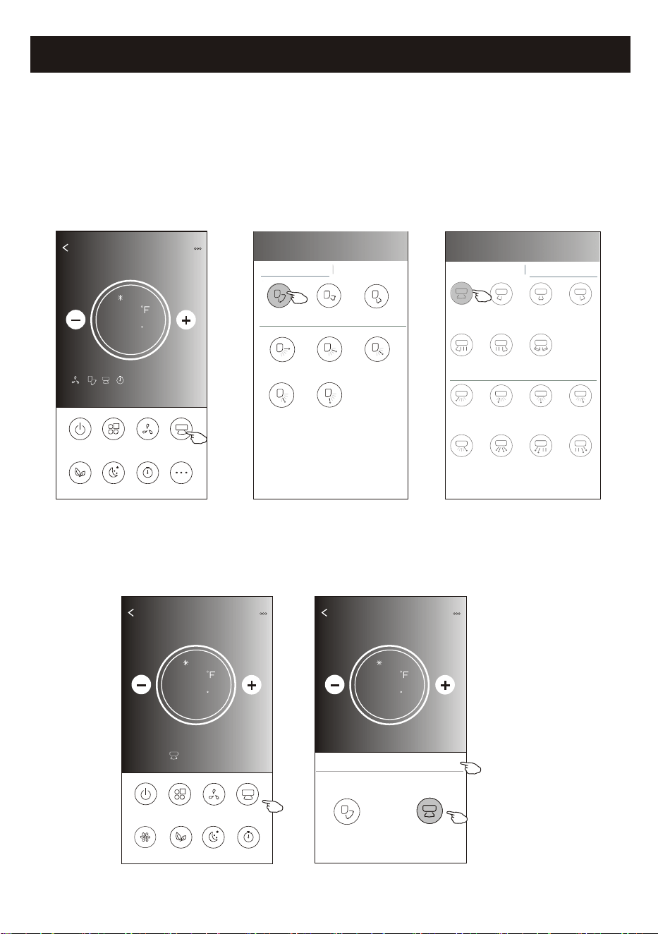
Air conditioner control
1.Tap the Precision Air Flow button or Swing Flow button.
2.Choose your desired air flow and tap it.
3.Tap the X button to back to the main control screen.
4.The selected air flow indicator will appear on the screen.
ON/OFF
Fan Speed
Precision
Air Flow
More
Eco Sleep
Mode
Timer
Sample1
77
Cool
0
17
ON/OFF
Sample1
77
Cool
0
Fan Speed
Swing Flow
Eco Sleep
Mode
Timer
Turbo
Left-Right Flow
Note: The Main control screen and Air Flow screen may appear slightly different ,
depending on the air conditioner model.Example as below:
Get verification code
< Precision Air Flow
Up-Down Flow Control Left-Right Flow Control
Downwards
Swing
Up-Down
Swing
Upwards
Swing
Middle Fix
Top Fix
Upper Fix
Lower Fix
Bottom Fix
< Precision Air Flow
Up-Down Flow Control Left-Right Flow Control
Right
Swing
Left-Right
Swing
Left
Swing
Middle
Swing
Center-Left
Swing
Center-Right
Swing
Wide
Swing
Center-Right
Fix
Left fix
Center-Left
Fix
Middle Fix
Right Wide
Angle Fix
Right Fix
Whole
Anger Fix
Left Wide
Angle Fix
Back
Sample1
77
Cool
0
Swing Flow
X
Up-Down
Left-Right
Note: For some models without auto Left-Right wind, If you active it, you will hear a beep,but no any actions.
Control form2-Air Flow control
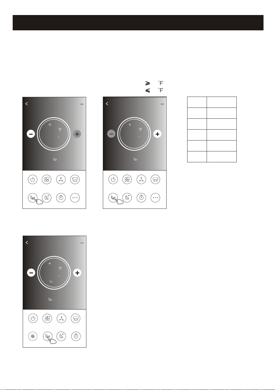
Air conditioner control
1.For Eco function, just tap the button to activate the function, the button will be lighting
and the indicator will appear on the screen.
2.Tap again to disable the function.
3.Temperature controlled for some air conditioner model:
In Cooling mode, the new setting temperature will 78 .
In heating mode, the new setting temperature will 77 .
ON/OFF
Fan Speed
Precision
Air Flow
More
Eco Sleep
Mode
Timer
Sample1
77
Heat
0
18
ON/OFF
Sample1
72
Cool
0
Fan Speed
Swing Flow
Eco Sleep
Mode
Timer
Turbo
Note: The Main control screen and ECO control method may appear slightly different ,
depending on the air conditioner model.Example as below:
ON/OFF
Fan Speed
Precision
Air Flow
More
Eco Sleep
Mode
Timer
Sample1
78
Cool
0
Mode
ECO enabled
Cool
Fan
Dry
Heat
Auto
Yes
Yes
ECO is disabled on Fan/ Dry/Auto mode .
Note:
ECO is disabled on Turbo/Sleep mode too
for some air conditioner model.
ECO
Low
Control form2-ECO function
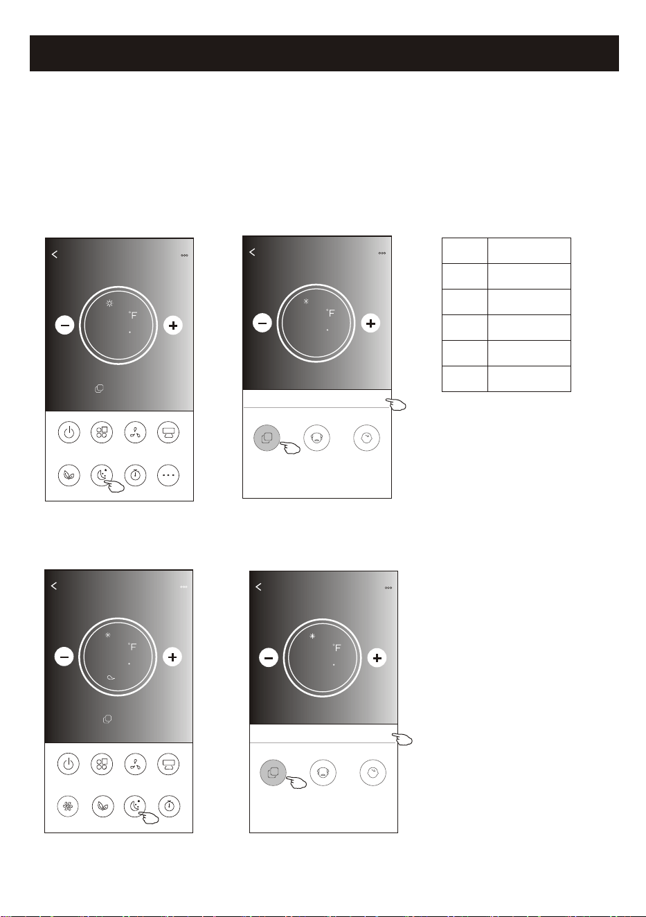
Air conditioner control
1.Tap the Sleep button.
2.Choose your desired sleep mode and tap it.
3.Tap the X button to back to the main control screen.
4.The selected sleep mode indicator will appear on the screen.
ON/OFF
Fan Speed
Precision
Air Flow
More
Eco Sleep
Mode
Timer
Sample1
77
Heat
0
19
ON/OFF
Sample1
72
Cool
0
Fan Speed
Swing Flow
Eco Sleep
Mode
Timer
Turbo
Note:
The Main control screen may appear slightly different ,depending on the air conditioner model.
Example as below:
Mode
Sleep enabled
Cool
Fan
Dry
Heat
Auto
Yes
Yes
Note:
Sleep is disabled on Turbo/Sleep mode too
for some air conditioner model..
Sleep
Low
Sleep is disabled on Fan/ Dry/Auto mode .
Sample1
77
Cool
0
Sleep
X
Standard
Child
The aged
Sample1
77
Cool
0
Sleep
X
Child
The aged
Standard
Control form2-Sleep function
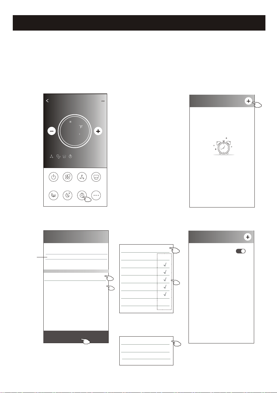
Air conditioner control
1.Tap the Timer button.
2.Tap + in the upper right corner of the Timer main screen.
3.Choose the Time/Repeat/Switch OFF then tap Save.
4.The timer(off) will appear on the Timer main screen.
ON/OFF
Fan Speed
Precision
Air Flow
More
Eco Sleep
Mode
Timer
Sample1
77
Cool
0
< Timer
No Timer
< Timer
19 27
20 28
22 30
23 31
Save
21 : 29
Repeat Monday.... >
Switch OFF>
Once
Monday
Tuesday
Wednesday
Thursday
Friday
Saturday
Sunday
Cancel Repeat Confirm
20
Slide up or down
to select time
Tap repeat > then tap your desired
repeat days or Once, then tap
Confirm your selection.
< Timer
21:29
OFF, Weekday
ON
Cancel Switch Confirm
OFF
Tap Switch > then slide the
screen to choose ON
and Confirm.
Control form2-Timer(on) setting
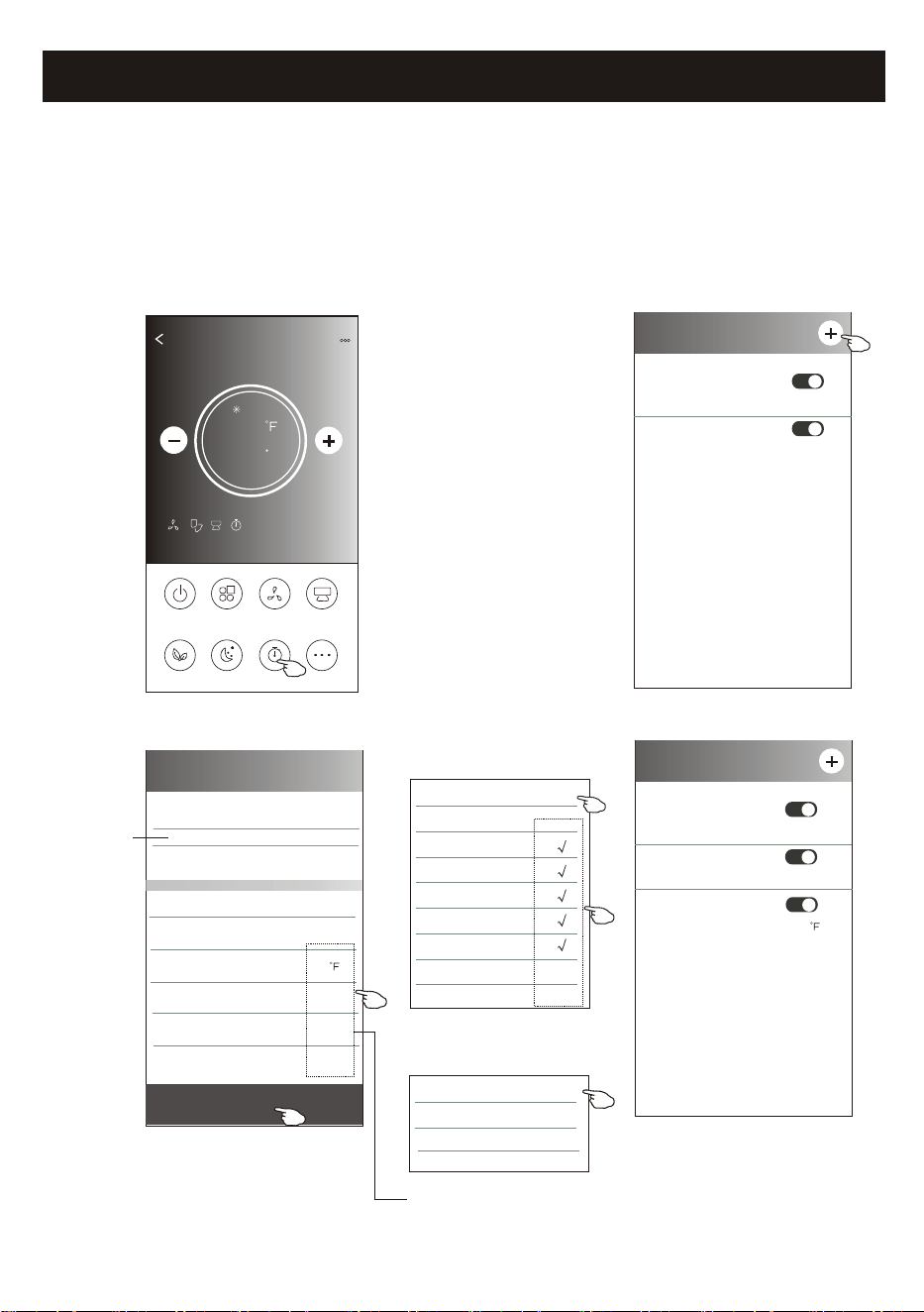
Air conditioner control
1.Tap the Timer button.
2.Tap + in the upper right corner of the Timer main screen.
3.Set the Time/Repeat Date/Switch(ON)/Temperature/Mode/
Fan speed/Air Flow as your desired and then tap Save.
4.The timer will appear on the Timer main screen.
ON/OFF
Fan Speed
Precision
Air Flow
More
Eco Sleep
Mode
Timer
Sample1
77
Cool
0
< Timer
14 17
15 18
17 20
18 21
Save
16 : 19
Repeat Monday.... >
Switch ON>
Temperature 77 >
Mode Cool>
Fan Speed Mid>
Precision Air Flow Up-Down Swing>
Slide up or down
to select time
21
Once
Monday
Tuesday
Wednesday
Thursday
Friday
Saturday
Sunday
Cancel Repeat Confirm
Tap repeat > then tap your desired
repeat days or Once, then tap
Confirm your selection.
< Timer
ON
Cancel Switch Confirm
OFF
Tap Switch > then slide the
screen to choose ON
and Confirm.
16:19
ON,Cool,Mid,Up-Down Swing ,M...77
< Timer
21:29
OFF, Weekday
Tap Temperature/Mode/Fan Speed/
Air Flow > one by one then set as your
desired as mentioned on the previous
chapter and tap Confirm the setting.
04:30
OFF
21:29
OFF, Weekday
04:30
OFF
Control form2-Timer(off) setting
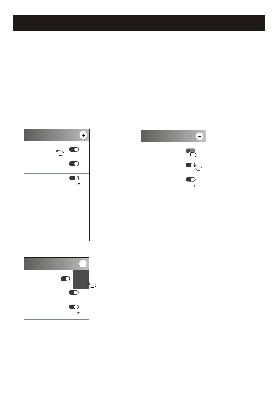
Air conditioner control
1.Change the Timer setting:
Tap anywhere of the timer list bar except the switch bar to get into the Timer
setting screen, change the setting and then tap save.
2.Enable or Disable the Timer:
Tap the left of the switch to disable the Timer.
Tap the right of the switch to enable the Timer.
3.Delete the Timer:
Slide the list bar of the Timer from right to left until Delete button appear,
then tap delete.
< Timer
16:19
ON,Cool,Mid,Up-Down Swing 77 ,M...
21:29
OFF, Weekday
04:30
OFF
22
< Timer
16:19
ON,Cool,Mid,Up-Down Swing ,M...77
21:29
OFF, Weekday
04:30
OFF
Slid left to disable the Timer.
Slid right to enable the Timer.
< Timer
16:19
ON,Cool,Mid,Up-Down Swing ,M...77
29
kday
04:30
OFF
Delete
Control form2-Timer management
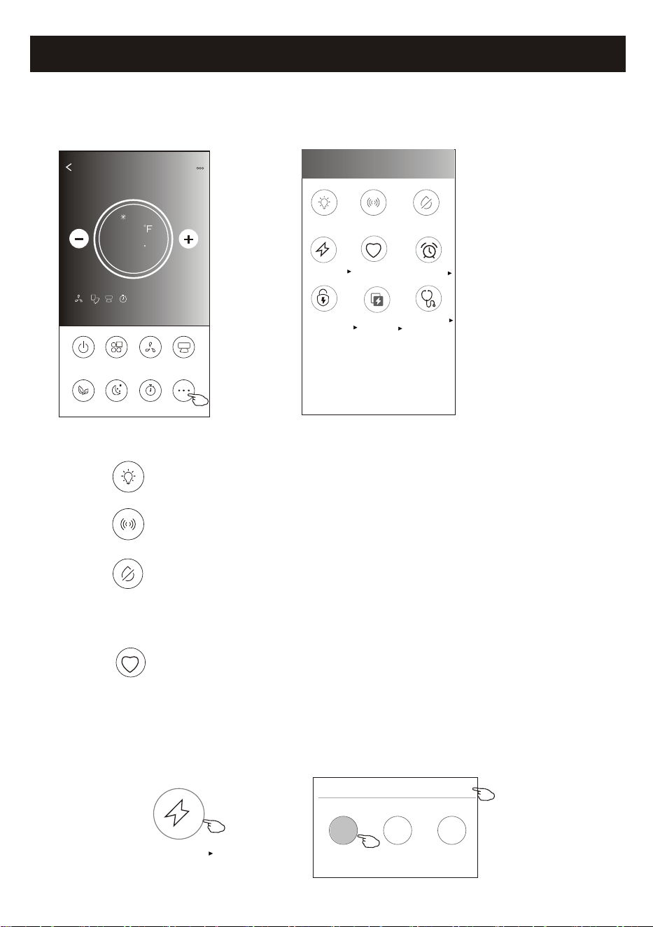
Air conditioner control
1.Tap the More button to operate additional functions if it appears on the screen.
ON/OFF
Fan Speed
Precision
Air Flow
More
Eco Sleep
Mode
Timer
Sample1
77
Cool
0
23
Note: The appearance maybe different , some icons
will be hidden if the air conditional do no have this
function or do not enable on the current mode.
< More
Buzzer
Anti-Mildew
Display
Health
Reservation
GEN Mode
Electricity
Monitoring
Self-diagnosis
Electricity
Management
2. Tap the to switch on/off the indoor LED display. " "
Display
3. Tap the to switch on/off the buzzing if it is available on the screen." "
Buzzer
Note:
Some air conditioner model
don't have the more button.
4. Tap the " " button to activate the Anti-Mildew function, if it is available on the screen.
After AC turning off , it will start drying , reduce residual moisture and prevent mould, after function
finish, it will automatically turn off.
Anti-Mildew
Health
5. Tap the " " button to switch on/off the healthy function, if it is available on the screen.
It activate the antibacterial ioniser function.This function only for models with the ioniser generator.
Control form2-More functions
6. Tap the "GEN Mode" button, if it is available on the screen.
In this Mode, you can choose one of the three levels of current.
The air conditioner will maintain proper current to save energy.
GEN Mode
GEN Mode
X
LV1
LV3
LV2
30%
80%
50%
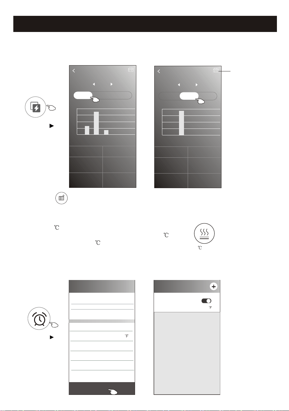
24
Air conditioner control
7. Tap the "Electricity Monitoring" button if it is available on the screen.
In this function, you can monitor the air conditioner electricity consumption.
Electricity monitoring
2019-03-11
DAY Month Year
2019-03-10 2019-03-11
0 kwh
Total Electricity
Consumption
0.14 kwh
Total Electricity
Consumption
4.6 hour
Running time statistics
0 hour
Running time statistics
13:00 14:00 15:00 16:00 17:00 18:00 19:00
(Kwh)
0.032
0.024
0.016
0.008
0
Electricity monitoring
2019-03
DAY Month Year
2019-02 2019-03
0.13 kwh
Total Electricity
Consumption
0.32 kwh
Total Electricity
Consumption
10.83 hour
Running time statistics
4.33hour
Running time statistics
03-09 03-10 03-11 03-12 03-13 03-14 03-15
(Kwh)
0.16
0.12
0.08
0.04
0
Electricity
Monitoring
You can tap this button to
pop up the calender then
select the date.
8. Tap the " " button, if it is available on the screen.
Check the details of the Self-Cleaning function on User Manual.
9. Tap the "8 Heat" button , if it is available on the screen.
This function help keep the room temperature over 8 .
Check the details of the 8 Heat function on User Manual.
Self-Cleaning
8 Heat
Control form2-More functions
10.Tap the "Reservation" button , if it is available on the screen.
You can set the time, repeat day, temperature, mode, fan speed, air flow as you desired
and then tap Save to activate the function.
The air conditioner will automatically reach your settings at the appointment time.
< Reservation
14 17
15 18
17 20
18 21
Save
16 : 19
Repeat setting Monday.... >
Temperature >
Mode Cool>
Fan Speed Mid>
Precision Air Flow Up-Down Swing>
77
< Reservation
16:19:00
ON,Cool,Mid,Up-Down Swing ,M...77
After the reservation is set up, the air conditioner
will automatically reach your set requirement at your
appointment time.
Reservation
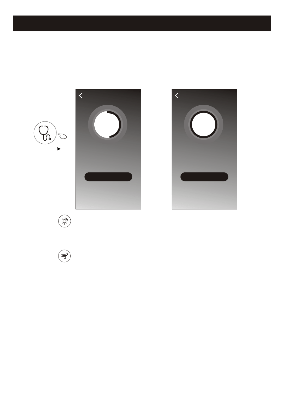
25
Air conditioner control
11.Tap the "Self-diagnosis" button, if it is available on the screen.
The air conditioner will automatically diagnosis itself and indicate the Error code
and the problem instructions if possible.
Self-diagnosis
48%
Checking
Cancel
48
OK
Self-diagnosis
100%
Complete
Error code: E0
Indoor and outdoor
communication failure
Self-diagnosis
Control form2-More functions
12. Tap the " " button if it is available on the screen.
13. Tap the " " button if it is available on the screen.
In this function, the air conditioner will blow soft airflow through the micro holes on the deflector.
Photosensitive
Soft Wind
This function allow the air conditioner to turn on/off the display automatically according to the
light intensity.
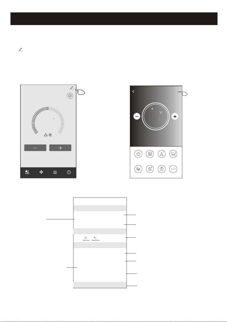
Air conditioner control
ON/OFF
Fan Speed
Precision
Air Flow
More
Eco Sleep
Mode
Timer
Sample1
77
Cool
0
Tap on control form1 or tap ... on control form2 , get into the device details screen.
Here you can get some useful information and sharing the device to other accounts.
Check the following pictures and instructions carefully.
26
72
F
Set Temperature
Timer
Function
Fan
Mode
Sample2
<
Control form2Control form1
<
Details of device
Information
Remove Device
Supported Third-part Control
Others
Modify Device Name *** >
Device Location Dining Room >
Check Device Network Check Now >
Device Sharing >
Device Info >
Feedback >
Check for Firmware Update >
Tap to change the device
location to another room
Tap to check the network status
Tap to got the instruction for connecting the
amazon alexa or Google Assistant voice controller
Tap to check the Virtual ID/Wi-Fi name/IP address
MAC address/Time Zone/Wi-Fi single strength
Feed back the problems or some
suggestions to the APP administrator.
Check and update the firmware
Tap to remove the device and the
device will be reset automatically
once be deleted.
Tap to check the network status
Tap to sharing the device to other account
Device details and management
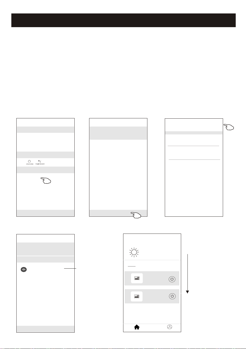
Air conditioner control
<
Details of device
Information
Remove Device
Supported Third-part Control
Others
Modify Device Name *** >
Device Location Dining Room >
Check Device Network Check Now >
Device Sharing >
Create Group >
Device Info >
Feedback >
Check for Firmware Update >
Device details and management
How to share the devices to other accounts?
1. Tap "Device Sharing" and pop up Device Sharing screen.
2. Tap "Add Sharing".
3. Select the region and enter the account which you want to sharing.
4. Tap "Completed", the account will appear on your sharing list.
5. The received sharing members should hold pressing the home screen and slide
down to refresh the device list, the device will appear on the device list.
<
Details of device
Adding sharing
It is recommended to set permanent resident as family
member to control the device Family Settings
<
Add Sharing Completed
Region China +86 >
Account
number
***********
<
Details of device
Adding sharing
It is recommended to set permanent resident as family
member to control the device Family Settings
Sharing List
Alias name1
************
Hold the bar about 3s
then you can delete the
sharing account.
27
<<
my home
+
>
Set your home location, get more
information
Welcome home
V
All Devices
Living Room
room
Master Bed
...
Home
Me
Sample1
Sample2
Turned off
Already On
Hold on and slide down to
refresh the device list
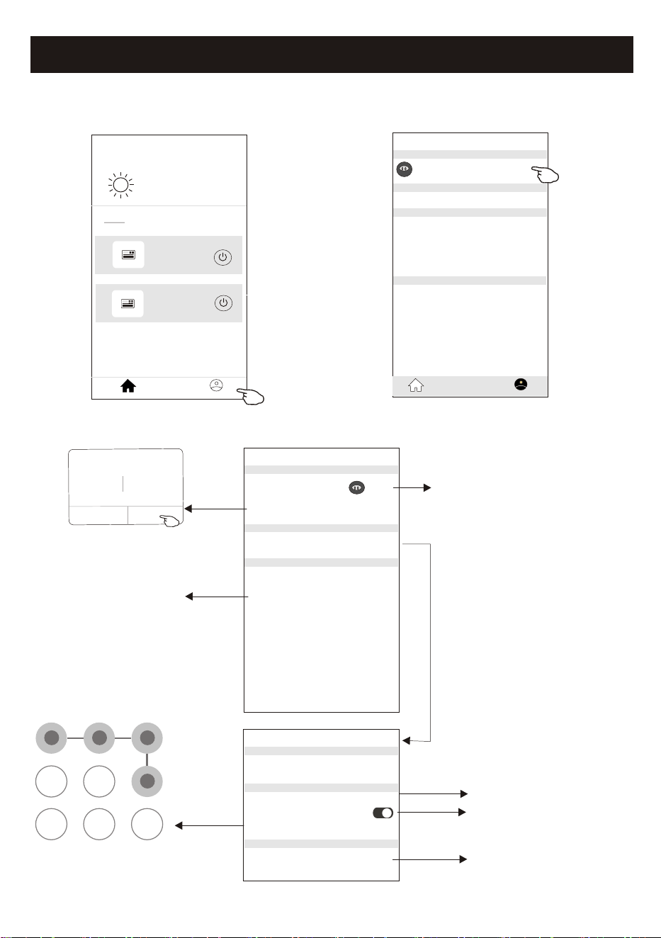
Account management
28
<<
my home
+
>
Set your home location, get more
information
Welcome home
V
All Devices
Living Room
room
Master Bed
...
Home
Me
Sample1
Sample2
Turned off
Already On
Profile
Nick name >
Account******
Message Center >
Help Center >
More Services >
Settings >
Home Management >
Home
Me
Account Profile setting
Profile
Profile Picture >
Account Security >
Time Zone Universal >
Nickname ******** >
Select a picture for the
account from local album
Edit name
Cancel Save
Account one
Select the time zone
Change the nick
name of your account
Account Security
Phone Number ********
Change Login Password >
Deactivate Account >
Location China
<
Pattern Unlock
Change Pattern Password >
Change the password
like reset password on page7
Please carefully to
deactivate the account
for all data will be deleted.
Set a pattern password
for launching the APP
Tap the switch to enable
or disable the Pattern password
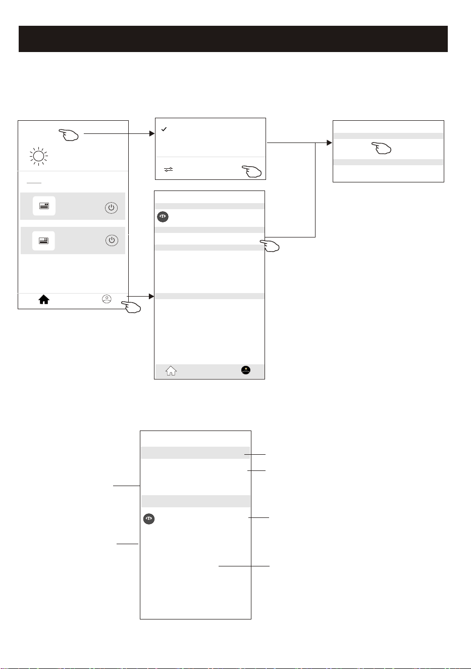
Account management
Home(Family) management
29
<<
My Home
+
>
Set your home location, get more
information
Welcome home
V
All Devices
Living Room
room
Master Bed
...
Home
Me
Sample1
Sample2
Turned off
Already On
Profile
Nick name >
Account******
Message Center >
Help Center >
More Services >
Settings >
Home Management >
Home
Me
Home Management
My Home >
My Office >
<
Add family
1.Tap the name of home at the left upper corner of the Home Screen and select the Home Management.
Or tap Me and tap Home Management.
2. Tap one of the families in the family list and get into Family Settings screen.
<
Family settings
Family members
Room Management 2 rooms >
Family Location >
Family Name My Home >
Remove Family
Add Menber
Nick name >
Account******
Tap to rename the family name
Tap to get into Room Management
Open the map automatically
then you can set the location
Add other account into this
family to control the device
Remove the Family
from your account
Home Management >
My Home
My Office
Tap to set a name and
select picture for the
family member
Note:
Tap "Add family"
and refer to page 6
to add a new family
3.Set the family as the following indicators.
30
Trouble Shooting
Notice
1. For technical update, there is maybe deviation of the actual items from what is on the manual. We
express our apologies. Please refer to your actual product and APP.
2. Smart air conditioner APP can be altered without notice for quality improvement and also be deleted
depending on the circumstances of manufacturing firms .
3. In case Wi-Fi signal strength is weakened, smart App may be disconnected. So make sure the indoor
unit near to wireless router.
4. DHCP server function should be activated for wireless router.
5. The internet connection may fail because of a firewall problem. In this case, contact your internet
service provider.
6. For smart phone system security and network setting, make sure Smart air conditioner APP is trusted.
Description
Analysis of cause
Air conditioner
can't be configured
successfully
1. Check the mobile connected WLAN router SSID and password is correct;
2. Check whether there are additional settings of WLAN router as shown below.
1) Firewall by router itself or by PC
2) MAC address filtering
3) Hidden SSID
4)DHCP server
Reboot WLAN router, mobile device and air conditioner (WLAN module) and connect air
conditioner by CF mode again. Before rebooting, check nobody has already connected to
same air conditioner.
1. When air conditioner (WLAN module) is rebooted and app
displays Device remove, ignoring this confirmation will lead to mobile
device losing control permission of the air conditioner.
You will need to connect the air conditioner by CF mode again.
2. In case of power failure, mobile device will lose control permission of air
conditioner for 3 minutes after power failure. (Notification will now show
up on the mobile device.)
If you cannot control the app (air conditioner) even after power restored,
you will need to connect the air conditioner by CF mode again.
Mobile can't control
air conditioner
1. App display Air conditioner Device offline. Please check the following conditions.
1)The air conditioner has been reconfigured.
2)Air conditioner out of power.
3)Router out of power.
4)Air conditioner can't connect to router.
5)Air conditioner can't connect to network through the router.
6)Mobile device can't connect to network.
2. After adding the device, it disappears in device list .
Hold and slide down to refresh the device list. If it has no change, shut down the app and start again.
Mobile can't find air
conditioner