MANUAL
Milo Series
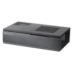
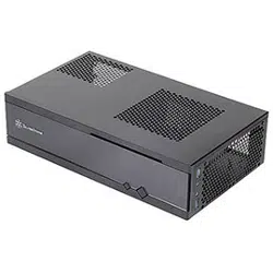
ML01
Specification:
Material: Aluminum front panel, 0.8mm SECC body
Color: Black & Silver
Model: ML01B( Black ) , ML01S(Silver)
ML01B-R(Black, card reader) , ML01S-R(Silver, card reader)
Motherboard: Micro ATX
Drive Bay: External - 5.25" x 1
External - 3.5" x 1
Internal - 3.5" x 1
Cooling System: Front - 80 x 15mm intake, 1800rpm, 19CFM, 20.65dBA
Left side - Dedicated CPU vent
Top side - Oversized mesh grille over CPU area
Expansion Slot: 4 x low profile
Front I/O Port: USB2.0 x 1, IEEE1394 x 1, audio x 1, MIC x 1
Card reader format (ML01R only):
MMC, SD, MD, CF, MS, SM, XD, MS PRO,
MS PRO DUO, MS DUO, MINI SD, RS MMC
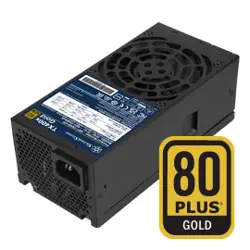
Power Supply: TFX 300W PFC
Net Weight: 5 kg
Dimension: 330mm (W) x 98mm (H) x 423mm (D)
ML01
Product Overview
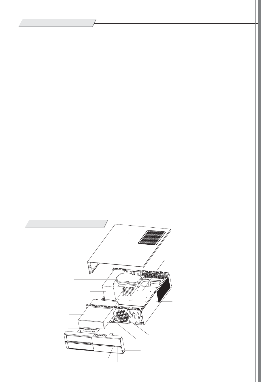
Disassemble Chart
TOP PANEL
HDD
TFX 300W PFC POWER SUPPLY
5.25 BAY*1
3.5 BAY*1
RESET SW
POWER SW
LEFT PANEL
FRONT IO(1394+AUDIO+USB)
8015 FAN
BOTTOM PANEL
MICRO ATX M/B
1
2
3
4
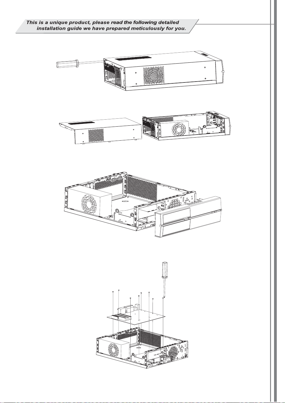
Use a screw driver to loosen two #6-32*6 screws on back side of the top panel.
Remove the top panel.
Lift the two latch hooks to remove the front panel.
Use the eight pieces of #6-32*4 screws in the accessory packet, screw the mother board on to the case as pictured.
78
5
6
Installation Guide
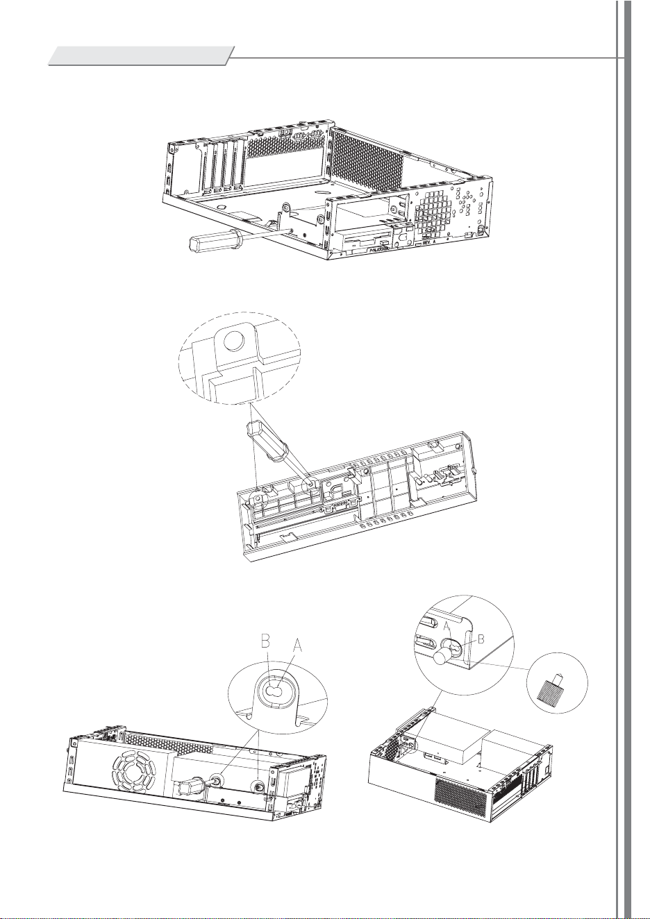
Take out two pieces of M3*4 screws, and secure the external 3.5"device as pictured.
Take out the external 3.5"drive bay cover from the front panel.
From the accessory packet, take out two pieces of M3*4
screws and screw the optical drive into place as pictured.
If optical drive cover on the front panel touches the optical
drive and prevents the front panel from installing properly,
use pre-drilled hole B to secure the optical drive instead,
then use of a rubber filler is then required as pictured.
Take out a thumb screw from the accessory packet
and secure the optical drive into place as pictured.
Plastic
thumb screw
9
10 11
12
Installation Guide
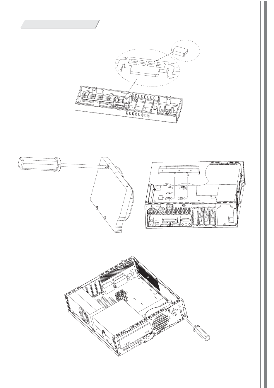
Rubber padding
Rubber padding placement
Take out the rubber padding and stick it right behind the optical drive buttons on the front panel.
Take out the three special hard-drive screws provided
in accessory packet (refer to photo), tighten those screws
into Hard Disk Drive as pictured.
Place the Hard Disk Drive into the case according
to the picture.
Take out one piece of M3*6 screw, use a screw driver to secure Hard Disk Drive into place as pictured.
13
14
15
16
Installation Guide
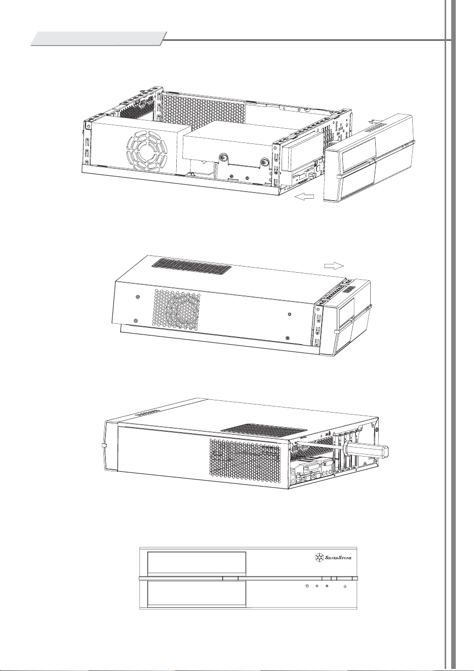
Place front panel back on the case and make sure it snaps into the latch hooks.
Put the top panel back on the case as pictured.
Make sure the top panel is securely fastened.
Installation complete!
Warranty Information
NO:G11400284
June , 2006