
E73-2G4M08S1C User Manual
nRF52840 2.4GHz SMD Wireless Module

Chengdu Ebyte Electronic Technology Co., Ltd. E73-2G4M08S1C User Manual
Copyright ©2012–2018
,
Chengdu Ebyte Electronic Technology Co., Ltd
1
Contents
1 Product overview
.................................................................................................................................................................
2
1.1 Brief Introduction
.....................................................................................................................................................
2
1.2 Features
.....................................................................................................................................................................
2
1.3 Application
................................................................................................................................................................
2
2 Specification and parameter
................................................................................................................................................
3
2.1 Limit parameter
........................................................................................................................................................
3
2.2 Operating parameter
.................................................................................................................................................
3
3 Size and pin definition
.........................................................................................................................................................
5
4 Development and Application
.............................................................................................................................................
7
5 Basic operation
....................................................................................................................................................................
8
5.1 Hardware design
.......................................................................................................................................................
8
6 FAQ
......................................................................................................................................................................................
9
6.1 Communication range is too short
............................................................................................................................
9
6.2Module is easy to damage
..........................................................................................................................................
9
6.3 BER(Bit Error Rate) is high
...................................................................................................................................
10
7 Production guidance
..........................................................................................................................................................
10
7.1 Reflow soldering temperature
................................................................................................................................
10
7.2 Reflow soldering curve
...........................................................................................................................................
11
8 E73 series
...........................................................................................................................................................................
11
9 Antenna recommendation
..................................................................................................................................................
12
9.1 Recommendation
....................................................................................................................................................
12
Revision history
....................................................................................................................................................................
12
About us
................................................................................................................................................................................
12
Chengdu Ebyte Electronic Technology Co., Ltd. E73-2G4M08S1C User Manual
Copyright ©2012–2018
,
Chengdu Ebyte Electronic Technology Co., Ltd
2
1 Product overview
1.1 Brief Introduction
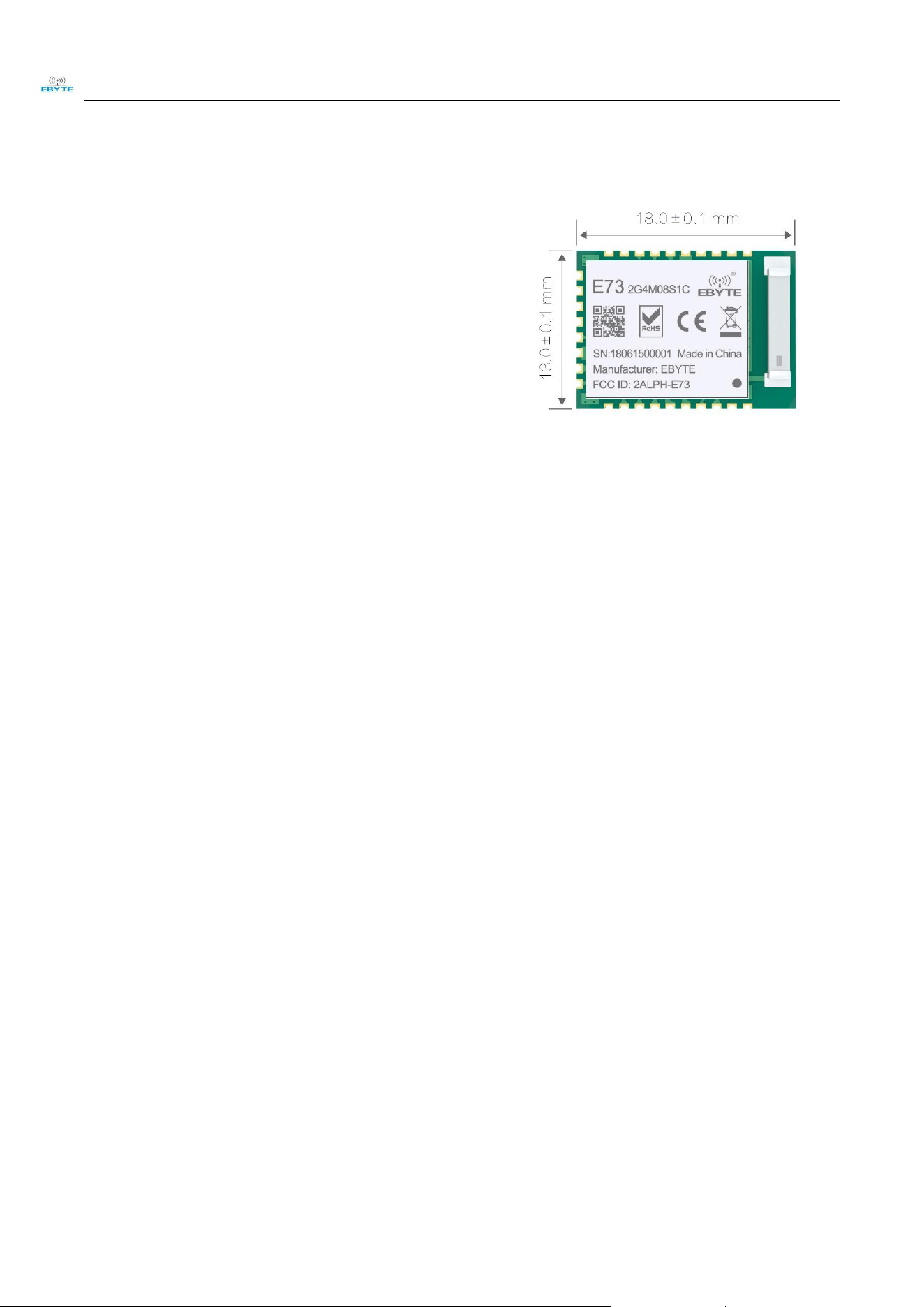
E73-2G4M08S1C are wireless Bluetooth modules designed by
Chengdu Ebyte which feature small size, low power consumption. It
adopt the originally imported RFIC nRF52840 of NORDIC,
supporting BLE 4.2 and BLE 5.0. The chip has high-performance
ARM CORTEX-M4F kernel and other peripheral resources, such as
UART, I2C, SPI, ADC, DMA, PWM etc. The module led out most
IO Port of nRF52840 for multilateral development.Please see the pin definition for details.
E73-2G4M08S1C is hardware platform without firmware, so users need to conduct a secondary development.The
characteristics of the nRF52840 chip can be found in the official Datasheet.
1.2 Features
Small size: 13x18mm;
Support BLE4.2 and BLE 5.0;
The measured communication distance is up to 120m;
Maximum transmission power of 6mW, software multi-level adjustable;
Support the global license-free ISM 2.4GHz band;
Built-in high performance low power ARM® and Cortex ® -M4 dual core processor;
Rich resources, 1024KB FLASH, 256KB RAM;
Support 1.7V~5.5Vpower supply, power supply over 3.3Vcan guarantee the best performance;
Industrial grade standard design, support -40 ~ 85 °C for working over a long time;
Built-in ceramic antenna, no antenna is required for the built-in antenna.
1.3 Application
Smart homes and industrial sensors;
Security system, positioning system;
Wireless remote control, drone;
Wireless game remote control;
Health care products;
Wireless voice, wireless headset;
Automotive industry applications.
Chengdu Ebyte Electronic Technology Co., Ltd. E73-2G4M08S1C User Manual
Copyright ©2012–2018
,
Chengdu Ebyte Electronic Technology Co., Ltd
3
2 Specification and parameter
2.1 Limit parameter
Main parameter
Performance
Remark
Min Max
Power supply (V) 1.7 5.5
Voltage over 5.5V will cause permanent
damage to module
Blocking power(dBm) - 9
Chances of burn is slim when modules
are used in short distance
Operating temperature(℃) -40 85
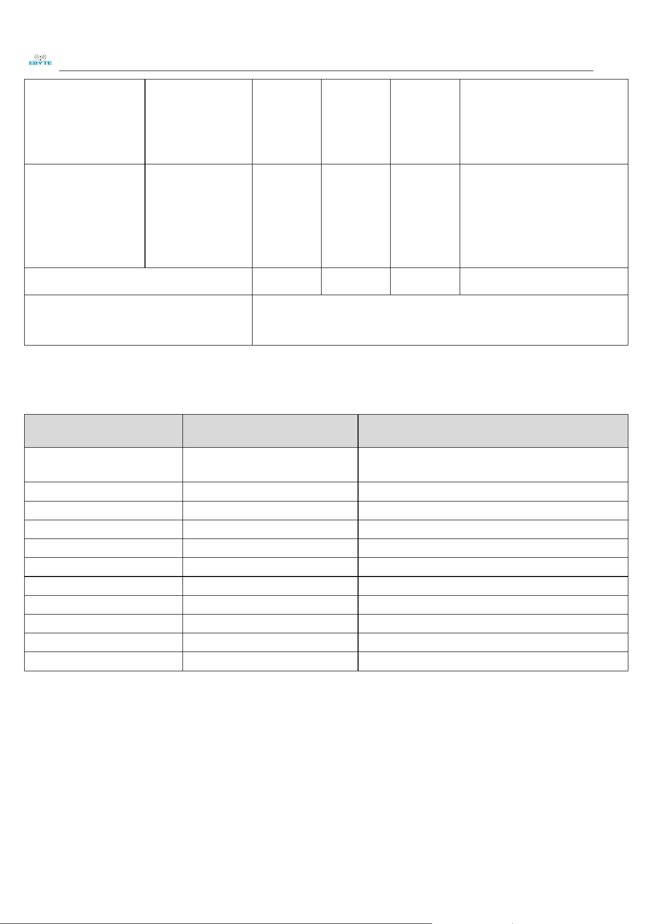
2.2 Operating parameter
Main parameter
Performance
Remark
Min Type Max
Operating voltage(V) 1.7 3.3 5.5 ≥3.3 V ensures output power
Communication level (V) - 3.3 -
For 5V TTL, it may be at risk of
burning down
Operating temperature (℃) -40 - 85 Industrial grade
Operating frequency(MHz) 2400 - 2483.5 Support ISM band
Transmitting current
TX only run current
(DC/DC, 3 V) PRF =
+8 dBm
- 17.05 -
mA
TX only run current
(DC/DC, 3 V) PRF =
+4 dBm
- 12.68 -
mA
TX only run current
(DC/DC, 5 V, REG0
out = 3.3 V)PRF =
0dBm
- 7.25 -
mA
TX only run current
(DC/DC, 3 V)P RF =
0 dBm
- 7.63 -
mA
Chengdu Ebyte Electronic Technology Co., Ltd. E73-2G4M08S1C User Manual
Copyright ©2012–2018
,
Chengdu Ebyte Electronic Technology Co., Ltd
4
TX only run current
(DC/DC, 3 V) PRF =
+8 dBm
- 17.05 -
mA
Receiving current
RX only run current
(DC/DC, 3 V) 1
Mbps / 1 Mbps BLE
- 7.71 - mA
Transmitting power -1 0 1 dBm
Receiving sensitivity -103 dBm@BLE 125kbps(long distance mode), -95 dBm@BLE 1M
Main parameter Description Remark
Reference distance 120m
Clear and open area, antenna gain: 3.85dBi, antenna height:
2.5m,air data rate: 1Mbps
Crystal Oscillator 32MHz
Protocol BLE 4.2/5.0
Package SMD
Interface 1.27mm Stamp hole/Ceramic antenna
IC nRF52840-QIAAC0/ aQFN ™ 73
FLASH 1024KB
RAM 256KB
Core ARM® Cortex ® -M4
Size 13.0 * 18.0 mm
Antenna ceramic antenna 50 ohm impedance
Chengdu Ebyte Electronic Technology Co., Ltd. E73-2G4M08S1C User Manual
Copyright ©2012–2018
,
Chengdu Ebyte Electronic Technology Co., Ltd
5
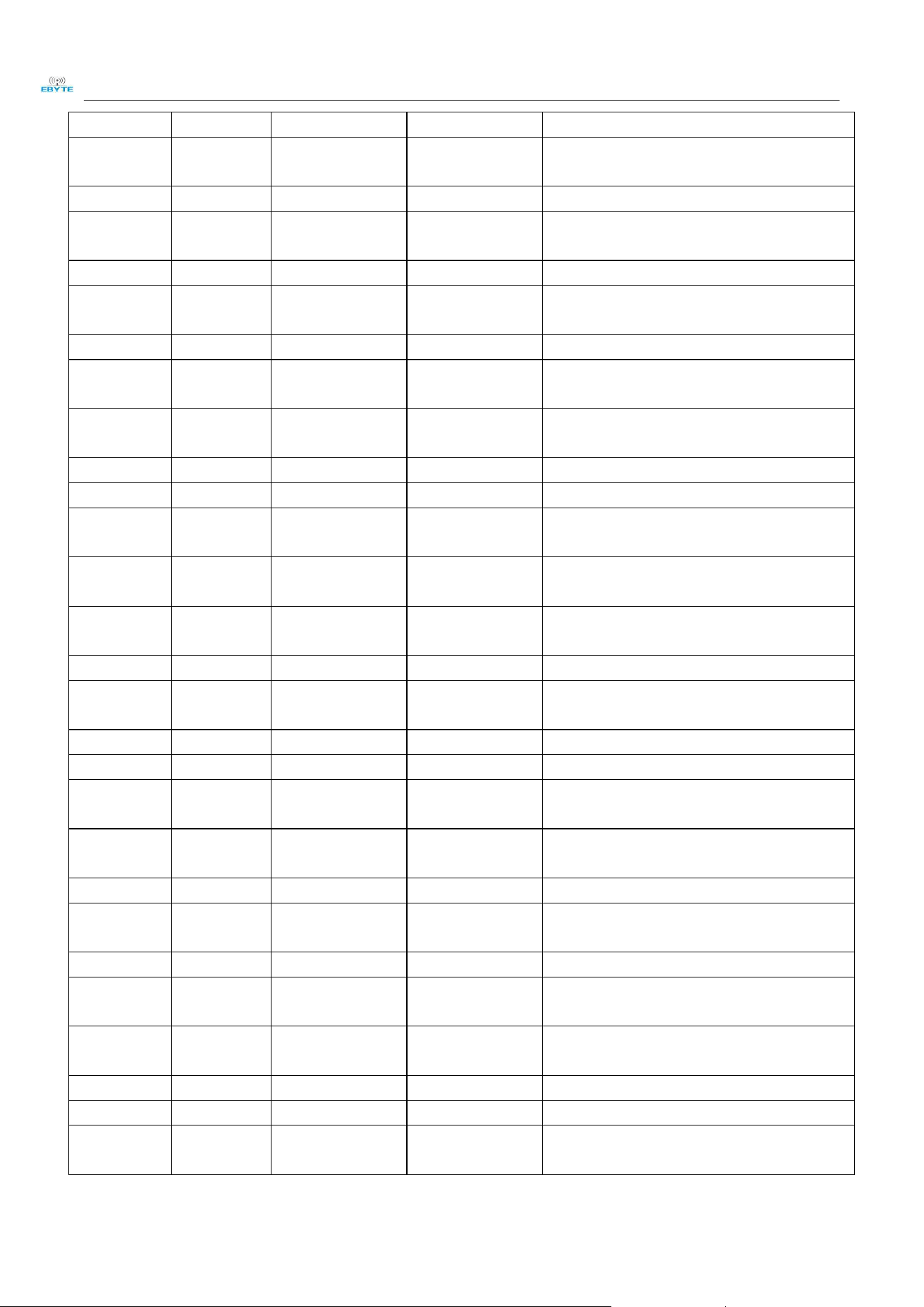
3 Size and pin definition
No. Pin item
Corresponding
chip pin item
Pin direction Application
1
P1.11 P1.11 Common I/O
See details about nrf52840 datasheet on Nordic
website
2
P1.10 P1.10 Common I/O Low frequency I/O, standard drive
3 P0.03 P0.03/AIN1 Common I/O
Analog input 1, low frequency I/O, standard
drive
4 AI4 P0.28/AIN4 Common I/O Analog input 4
5 GND - -
Single ground line
,
connect to the power
reference ground
6
P1.13 P1.13 Common I/O Low frequency I/O, standard drive
7
AI0 P0.02/AIN0 Common I/O
Analog input 0, low frequency I/O, standard
drive
8
AI5 P0.29/AIN5 Common I/O
Analog input 5, low frequency I/O, standard
drive
9 AI7 P0.31/AIN7 Common I/O Analog input 7, low frequency I/O, standard
Chengdu Ebyte Electronic Technology Co., Ltd. E73-2G4M08S1C User Manual
Copyright ©2012–2018
,
Chengdu Ebyte Electronic Technology Co., Ltd
6
drive
10 AI6 P0.30/AIN6 Common I/O
Analog input 6, low frequency I/O, standard
drive
11 XL1 P0.00/XL1 Common I/O Connect to 32.768 kHz crystal
12
P0.26 P0.26 Common I/O
See details about nrf52840 datasheet on Nordic
website
13
XL2 P0.01/XL2 Common I/O Connect to 32.768 kHz crystal
14 P0.06 P0.06 Common I/O
See details about nrf52840 datasheet on Nordic
website
15 AI3 P0.05/AIN3 Common I/O Analog input 3
16 P0.08 P0.08 Common I/O
See details about nrf52840 datasheet on Nordic
website
17 P1.09 P1.09 Common I/O
See details about nrf52840 datasheet on Nordic
website
18
AI2 P0.04/AIN2 Common I/O Analog input 2
19
VDD - - Power supply
20 P12 P0.12 Common I/O
See details about nrf52840 datasheet on Nordic
website
21 GND - -
ground line
,
connect to the power reference
ground
22 P0.07 P0.07 Common I/O
See details about nrf52840 datasheet on Nordic
website
23 VDH VDDH - High-voltage power supply
24
GND - -
ground line
,
connect to the power reference
ground
25
DCH DCCH - DC/DC Converter output
26 RST P0.18/RESET Common I/O QSPI/CSN/external reset
27 VBS VBUS -
USB power supply
,
5V input
,
used to
USB3.3V voltage regulator
28 P15 P0.15 Common I/O
See details about nrf52840 datasheet on Nordic
website
29 D- - - USB D-
30
P17 P0.17 Common I/O
See details about nrf52840 datasheet on Nordic
website
31
D+ - - USB D+
32 P0.20 P0.20 Common I/O
See details about nrf52840 datasheet on Nordic
website
33 P0.13 P0.13 Common I/O
See details about nrf52840 datasheet on Nordic
website
34 P0.22 P0.22 Common I/O QSPI
35 P0.24 P0.24 Common I/O
36
P1.00 P1.00 Common I/O
See details about nrf52840 datasheet on Nordic
website
Chengdu Ebyte Electronic Technology Co., Ltd. E73-2G4M08S1C User Manual
Copyright ©2012–2018
,
Chengdu Ebyte Electronic Technology Co., Ltd
7
37 SWD SWDIO - Serial debug programming port data
38 P1.02 P1.02 Common I/O
See details about nrf52840 datasheet on Nordic
website
39 SWC SWDCLK - Serial debug programming port clock
40
P1.04 P1.04 Common I/O Low frequency I/O, standard drive
41
NF1 P0.09/NFC1 Common I/O NFC input
42 P1.06 P1.06 Common I/O Low frequency I/O, standard drive
43 NF2 P0.10/NFC2 Common I/O NFC input
4 Development and Application
No. Item Notes
1
Burn
Firmware
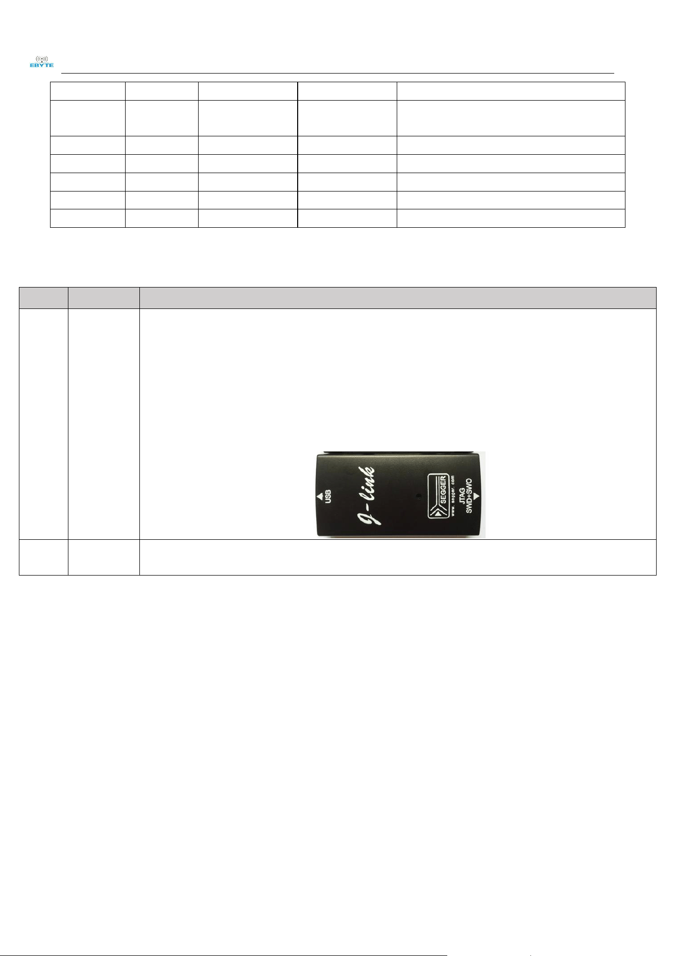
1.The module is embedded with ARM MCU. For program downloading, please use the J-LINK downloader.
Any other serial port or JTAG、ISP、ICP are unavailable to download.
1.The burn firmware needs to be completed in two parts. Since the protocol stack provided by NORDIC is not
loaded in the program, in the second development, you need to use the official burning tool nRFgo studio to
burn the protocol stack, and then use nRFgo studio to burn. The hex of the application code; you can also use
the official burning tool nRFgo studio to burn the protocol stack, and then download it with IAR or KEIL.
Website of tool download:
http://www.nordicsemi.com/eng/Products/Bluetooth-low-energy/nRF52832/(language)/eng-GB
2
Testing
Board
Testing board is not available.

Chengdu Ebyte Electronic Technology Co., Ltd. E73-2G4M08S1C User Manual
Copyright ©2012–2018
,
Chengdu Ebyte Electronic Technology Co., Ltd
8
5 Basic operation
5.1 Hardware design
It is recommended to use a DC stabilized power supply. The power supply ripple factor is as small as possible and
the module needs to be reliably grounded.
Please pay attention to the correct connection of the positive and negative poles of the power supply, reverse
connection may cause permanent damage to the module.
Please check the power supply to ensure that between the recommended supply voltage, if exceeding the maximum,
the module will be permanently damaged;
Please check the stability of the power supply. Voltage can not fluctuate greatly and frequently;
When designing the power supply circuit for the module, it is often recommended to reserve more than 30% of the
margin, so the whole machine is beneficial for long-term stable operation;
The module should be as far away as possible from the power supply, transformers, high-frequency wiring and other
parts with large electromagnetic interference;
Bottom Layer High-frequency digital routing, high-frequency analog routing, and power routing must be avoided
under the module. If it is necessary to pass through the module, assume that the module is soldered to the Top Layer,
and the copper is spread on the Top Layer of the module contact part(well grounded), it must be close to the digital
part of the module and routed in the Bottom Layer;

Chengdu Ebyte Electronic Technology Co., Ltd. E73-2G4M08S1C User Manual
Copyright ©2012–2018
,
Chengdu Ebyte Electronic Technology Co., Ltd
9
Assuming the module is soldered or placed over the Top Layer, it is wrong to randomly route over the Bottom Layer
or other layers, which will affect the module's spurs and receiving sensitivity to varying degrees;
It is assumed that there are devices with large electromagnetic interference around the module that will greatly
affect the performance. It is recommended to keep them away from the module according to the strength of the
interference. If necessary, appropriate isolation and shielding can be done;
Assume that there are traces with large electromagnetic interference (high-frequency digital, high-frequency analog,
power traces) around the module that will greatly affect the performance of the module. It is recommended to stay
away from the module according to the strength of the interference.If necessary, appropriate isolation and shielding
can be done;
If the communication line uses a 5V level, a 1k-5.1k resistor must be connected in series (not recommended, there is
still a risk of damage);
Try to stay away from some physical layers such as TTL protocol at 2.4GHz , for example: USB3.0;
The mounting structure of antenna has a great influence on the performance of the module. It is necessary to ensure
that the antenna is exposed, preferably vertically upward. When the module is mounted inside the case, use a good
antenna extension cable to extend the antenna to the outside;
The antenna must not be installed inside the metal case, which will cause the transmission distance to be greatly
weakened.
6 FAQ
6.1 Communication range is too short
The communication distance will be affected when obstacle exists;
Data lose rate will be affected by temperature, humidity and co-channel interference;
The ground will absorb and reflect wireless radio wave, so the performance will be poor when testing near ground;
Sea water has great ability in absorbing wireless radio wave, so performance will be poor when testing near the sea;
The signal will be affected when the antenna is near metal object or put in a metal case;
Power register was set incorrectly, air data rate is set as too high (the higher the air data rate, the shorter the
distance);
The power supply low voltage under room temperature is lower than recommended value, the lower the voltage, the
lower the transmitting power;
Due to antenna quality or poor matching between antenna and module.
6.2 Module is easy to damage
Please check the power supply and ensure it is within the recommended range. Voltage higher than the peak will
lead to a permanent damage to the module.
Please check the stability of power supply and ensure the voltage not to fluctuate too much.
Please make sure anti-static measures are taken when installing and using, high frequency devices have electrostatic
susceptibility.
Please ensure the humidity is within limited range for some parts are sensitive to humidity.
Please avoid using modules under too high or too low temperature.
Chengdu Ebyte Electronic Technology Co., Ltd. E73-2G4M08S1C User Manual
Copyright ©2012–2018
,
Chengdu Ebyte Electronic Technology Co., Ltd
10
6.3 BER(Bit Error Rate) is high
Here are co-channel signal interference nearby, please be away from interference sources or modify frequency and
channel to avoid interference;
Poor power supply may cause messy code. Make sure that the power supply is reliable;
The extension line and feeder quality are poor or too long, so the bit error rate is high.
7 Production guidance
7.1 Reflow soldering temperature
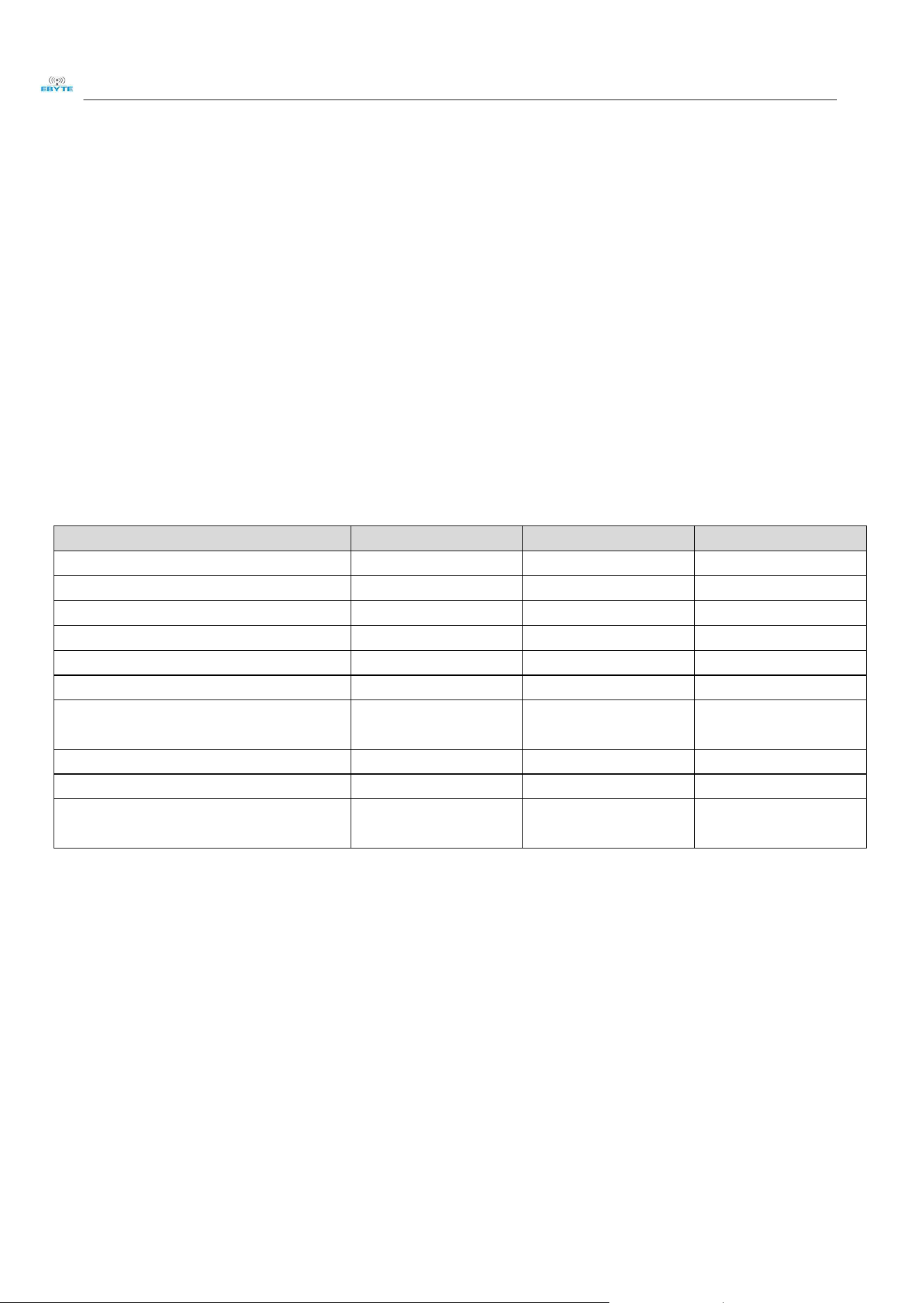
Profile Feature 曲线特征 Sn-Pb Assembly Pb-Free Assembly
Solder Paste Solder paste Sn63/Pb37 Sn96.5/Ag3/Cu0.5
Preheat Temperature min (Tsmin) Min preheating temp. 100℃ 150℃
Preheat temperature max (Tsmax) Max preheating temp. 150℃ 200℃
Preheat Time (Tsmin to Tsmax)(ts) Preheating time 60-120 sec 60-120 sec
Average ramp-up rate(Tsmax to Tp) Average ramp-up rate 3℃/second max 3℃/second max
Liquidous Temperature (TL) Liquid phase temp 183℃ 217℃
Time(tL)Maintained Above(TL)
Time below liquid phase
line
60-90 sec 30-90 sec
Peak temperature(Tp) Peak temp 220-235℃ 230-250℃
Aveage ramp-down rate(Tp to Tsmax) Average ramp-down rate 6℃/second max 6℃/second max
Time 25℃ to peak temperature
Time to peak
temperature for 25℃
6 minutes max 8 minutes max
Chengdu Ebyte Electronic Technology Co., Ltd. E73-2G4M08S1C User Manual
Copyright ©2012–2018
,
Chengdu Ebyte Electronic Technology Co., Ltd
11
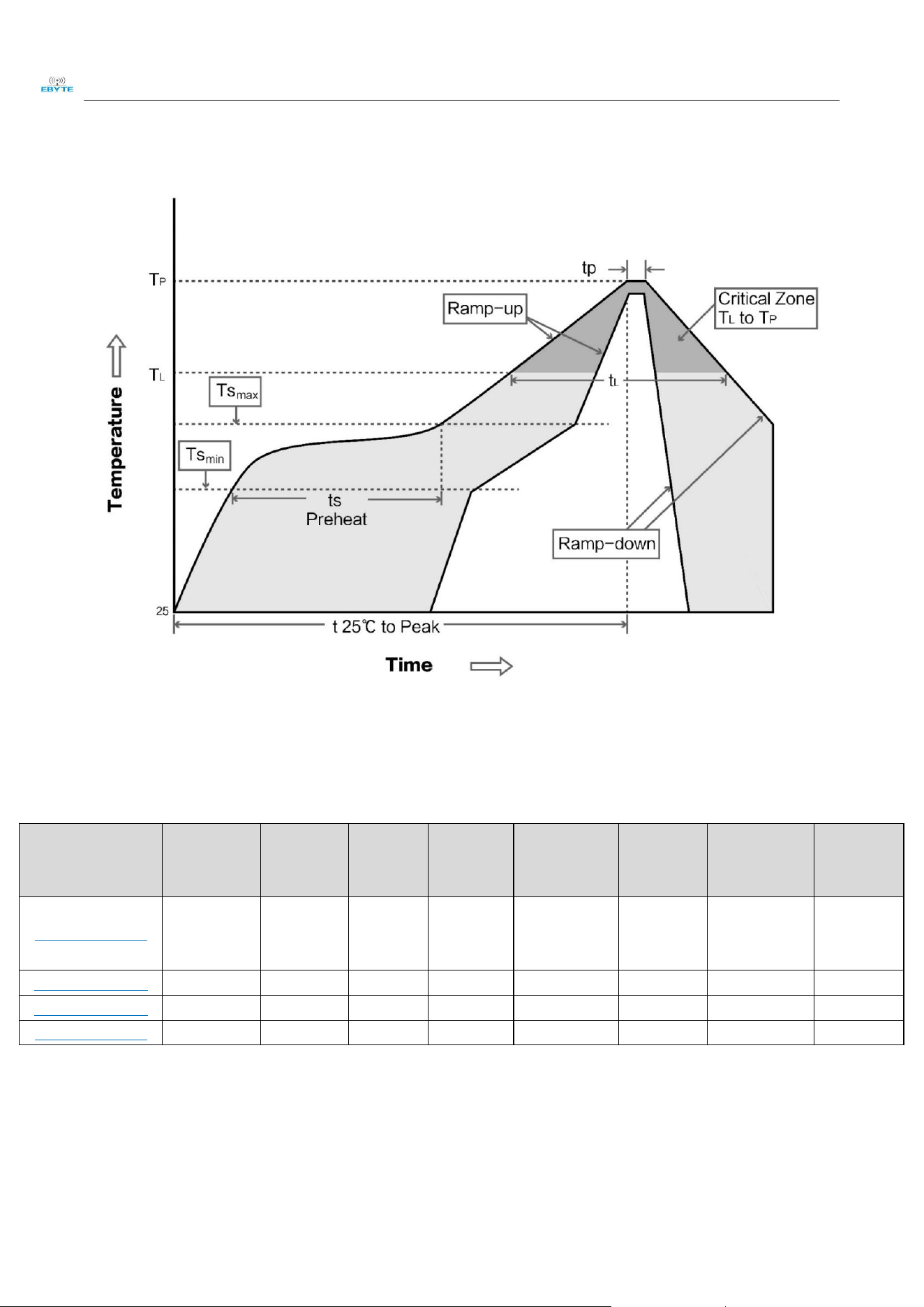
7.2 Reflow soldering curve
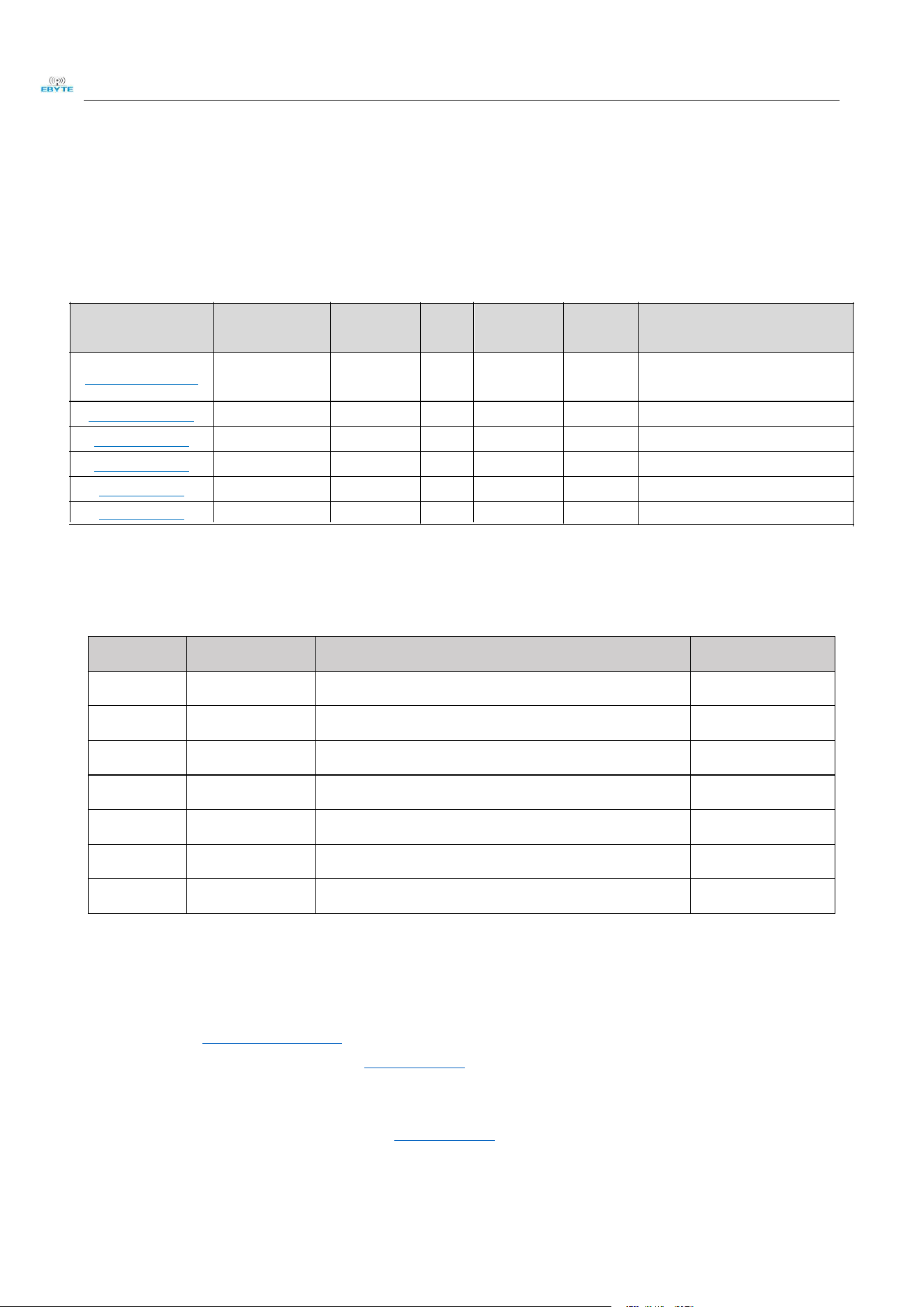
8 E73 series
Model IC
Frequency
Hz
Tx
power
dBm
Distance
km
Protocol Package
Size
mm
Antenna
E73-2G4M08S1C nRF52840 2.4G 8 0.1 BLE 4.2/5.0 SMD 13.0 * 18.0
Ceramic
antenna/Sta
mp hole
E73-2G4M04S1A
nRF52810 2.4G 4 0.1 BLE 4.2/5.0 SMD 17.5 * 28.7 PCB/IPX
E73-2G4M04S1D
nRF51822 2.4G 4 0.1 BLE 4.2 SMD 17.5 * 28.7 PCB/IPX
E73-2G4M04S1B nRF52832 2.4G 4 0.1 BLE 4.2/5.0 SMD 17.5 * 28.7 PCB/IPX
Chengdu Ebyte Electronic Technology Co., Ltd. E73-2G4M08S1C User Manual
Copyright ©2012–2018
,
Chengdu Ebyte Electronic Technology Co., Ltd
12
9 Antenna recommendation
9.1 Recommendation
The antenna is an important role in the communication process. A good antenna can largely improve the
communication system.
Model No. Type Connector
Gain
dBi
Height Cable Feature
TX2400-NP-5010
Flexible
Antenna
IPEX 2 50*10mm - FPC soft antenna
TX2400-XP-150
Sucker antenna SMA-J 3.5 15cm 150cm High Gain
TX2400-JK-20
Rubber antenna SMA-J 3 200mm - Flexible&omnidirectional
TX2400-JK-11
Rubber antenna SMA-J 2.5 110mm - Flexible&omnidirectional
TX2400-JZ-3
Rubber antenna SMA-J 2 30mm - Short straight &omnidirectional
Revision history
Version Date Description Issued by
1.00 2018/8/30 Initial version huaa
1.10 2018/9/28 Version split huaa
1.40 2018/11/6 new version update Huaa
1.5 2019/2/19 Content modification Ray
1.7 2019/8/20 Contect updated lyl
1.8 2019/11/06 Content modification Ren
1.9 2020/03/30 Ren
About us
Technical support: support@cdebyte.com
Documents and RF Setting download link::www.ebyte.com
Thank you for using Ebyte products! Please contact us with any questions or suggestions: info@cdebyte.com
-------------------------------------------------------------------------------------------------
Official hotline:028-61399028 ext. 821 Web: www.ebyte.com
Address: Innovation Center D347, 4# XI-XIN Road,Chengdu, Sichuan, China
SLDA92-2R660G-S1TF
Chip antenna - 3.85 1.6mm - Omnidirectional

Chengdu Ebyte Electronic Technology Co., Ltd. E73-2G4M08S1C User Manual
Copyright ©2012–2018
,
Chengdu Ebyte Electronic Technology Co., Ltd
13
FCC Caution.
This device complies with part 15 of the FCC Rules. Operation is subject to the following two
conditions:
(1) This device may not cause harmful interference, and
(2) this device must accept any interference received, including interference that may cause
undesired operation.
Any Changes or modifications not expressly approved by the party responsible for compliance
could void the user's authority to operate the equipment.
Note: This equipment has been tested and found to comply with the limits for a Class B digital
device, pursuant to part 15 of the FCC Rules. These limits are designed to provide reasonable
protection against harmful interference in a residential installation. This equipment generates
uses and can radiate radio frequency energy and, if not installed and used in accordance with the
instructions, may cause harmful interference to radio communications. However, there is no
guarantee that interference will not occur in a particular installation. If this equipment does
cause harmful interference to radio or television reception, which can be determined by turning
the equipment off and on, the user is encouraged to try to correct the interference by one or
more of the following measures:
-Reorient or relocate the receiving antenna.
-Increase the separation between the equipment and receiver.
-Connect the equipment into an outlet on a circuit different from that to which the receiver is
connected.
-Consult the dealer or an experienced radio/TV technician for help.

KDB 996369 D03 statements
2.2 List of applicable FCC rules:
The module complies with FCC Part 15.247.
FCC ID: 2AK6D-E73-2G4M08S1C on User manual and on the external of the packaging.
2.3 Summarize the specific operational use conditions
The module has been certified for Potable applications. This transmitter must not beco-located or
operating in conjunction with any other antenna or transmitter
2.4 Limited module procedures
The module is not a limited module.
2.5 Trace antenna designs
Not applicable
2.6 RF exposure considerations
This equipment complies with FCC’s RF radiation exposure limits set forth for an
uncontrolled environment. The antenna(s) used for this transmitter must not be collocated or operating
in conjunction with any other antenna or transmitter.
2.7 Antennas
The EUT use a permanently attached antenna which are refer to page 12.
2.8 Label and compliance information
The host system using this module, should have label in a visible area indicated the
following texts: “Contains FCC ID: 2AK6D-E73-2G4M08S1C
2.9 Information on test modes and additional testing requirements
When testing host product, the host manufacture should follow FCC KDB Publication 996369 D04
Module Integration Guide for testing the host products. The host manufacturer may operate their
product during the measurements. In setting up the configurations, if the pairing and call box options
for testing does not work, then the host product manufacturer should coordinate with the module
manufacturer for access to test mode software.
The module has been certified for Potable applications. This transmitter must not be
co-located or operating in conjunction with any other antenna or transmitter
2.10 Additional testing, Part 15 Subpart B disclaimer
The module without unintentional-radiator digital circuity, so the module does not
require an evaluation by FCC Part 15 Subpart B. The host shoule be evaluated by the FCC Subpart B.
2.11 Note EMI Considerations
host manufacture is recommended to use D04 Module Integration Guide recommending as
"best practice" RF design engineering testing and evaluation in case non-linear interactions generate
additional non-compliant limits due to module placement to host components or properties
2.12 How to make changes
This module is stand-alone modular. If the end product will involve the Multiple simultaneously
transmitting condition or different operational conditions for a stand-alone modular transmitter in
evaluation (i.e., no C2PC required when no emission exceeds the limit of any individual device
(including unintentional radiators) as a composite. The host manufacturer must fix any failure
a host, host manufacturer have to consult with module manufacturer for the installation method in end
system. According to the KDB 996369 D02 Q&A Q12, that a host manufacture only needs to do
anevaluation (i.e., no C2PC required when no emission exceeds the limit of any individual device(including
unintentional radiators) as a composite. The host manufacturer must fix any failure