Connect Family
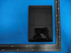
ProductName:TabletPC
RE667X-PRO
Connect Family
RE667-Pro
Slimline Touchpad
I
The RE667-Pro Slimline Touchpad is an intuitive interface for controlling the security system. It is powered
by...
It operates on alternating current (AC) and communicates with the control panel wirelessly.
Characteristics
• Vibrant 7-inch Android™ tablet display
•
Provides local control over security and automation functions.
• Mounting options for walls or desks.
• Encrypted Wi-Fi™ connection, available for Connect+™ and supported by battery power
Installation Overview of Connect+
1. Select the mounting location: The touchpad can be installed on a wall or a desk.
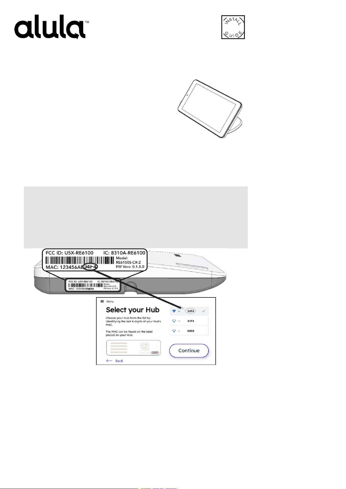
2. Identify your security hub and check the signal strength before installing it.
permanently.
1. Ensure the panel/hub is powered on.
2. Turn on the touchpad by connecting it to AC power. It will operate on AC.
3. Select "Start". A list of security hubs will then be displayed.
The device contains the necessary cables. If the "Start" option is not available, press
"Menu" and then select "factory default value".
4. Once you have selected the hub, check the signal strength. If the signal is weaker than 35, relocate
the touchpad or the Connect panel. If that is not possible, install the RE621 component.
Range Extender for Touchpad.

3. Select your security hub by entering the last four digits of its MAC address. Then click "Continue".
4. Set the Connect+ to recording mode by pressing the recording button on the side of the device for 2
–
3 seconds. Upon entering recording
mode, the device will emit a beep sound and the red recording LED will start blinking. Once this is completed...
Complete the touchpad registration; a message will appear stating "Connection successful on the touchpad." Select "Continue."
Note: If you have selected the wrong panel, click the "Reset" button in the side menu.
Troubleshooting if enrollment fails:
·
Confirm that the panel is disassembled and in winding mode. A red light will flash on the
panel when it is in winding mode.
· Check whether the panel is already full; the maximum number of touchpads allowed is four. To
confirm the number of touchpads connected, log in to your account.
Press the "Replay" button to try again.
5. Connect to Wi-Fi to enable updates for the camera and user code.
Management, user interface, and other functions related to the cloud; or skip this step if you don't have the necessary permissions.
Wi-Fi: When connecting to Wi-Fi, ensure that the signal strength is greater than 35.
Select your network and click "Continue." Enter the Wi-Fi password and make your selection.
"Continue." Once completed, a message will appear: "Connection successful. Select..."
Continue.
Note: The Connect+ must be connected to the same Ethernet network to access cameras, user management functions, users, and climate control
settings. If your panel is not connected to the same network, we also recommend connecting it to Wi-Fi for touchpad updates. The touchpad
cannot connect to the panel via an open or insecure network.
6. Install the touchpad. Refer to the "Touchpad Installation Options" section for installation instructions.
7. If you are using camera or user management features, users must log in to Alula Cloud as the account owner. To log in, go to Settings and
select Touchpad; enter your username and password, then choose Alula Cloud.
8. Test the Armando touchpad and disassemble the panel from the touchpad itself.
Mounting Options
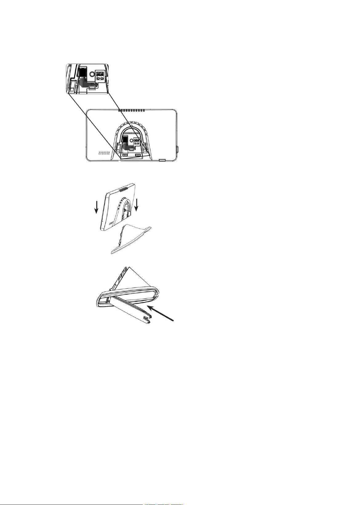
Table Assembly
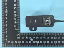
1. Connect the power adapter by inserting the connector into the black port. Once inserted, turn the connector to the right to secure it in place.
2. Slide the touchpad onto its base. The fit should be quite tight, so you may need to apply some pressure to ensure the base fits properly in place.
3. Insert the Power Cable into the holder and close the cover to secure the cables inside.
4. Connect the power supply.
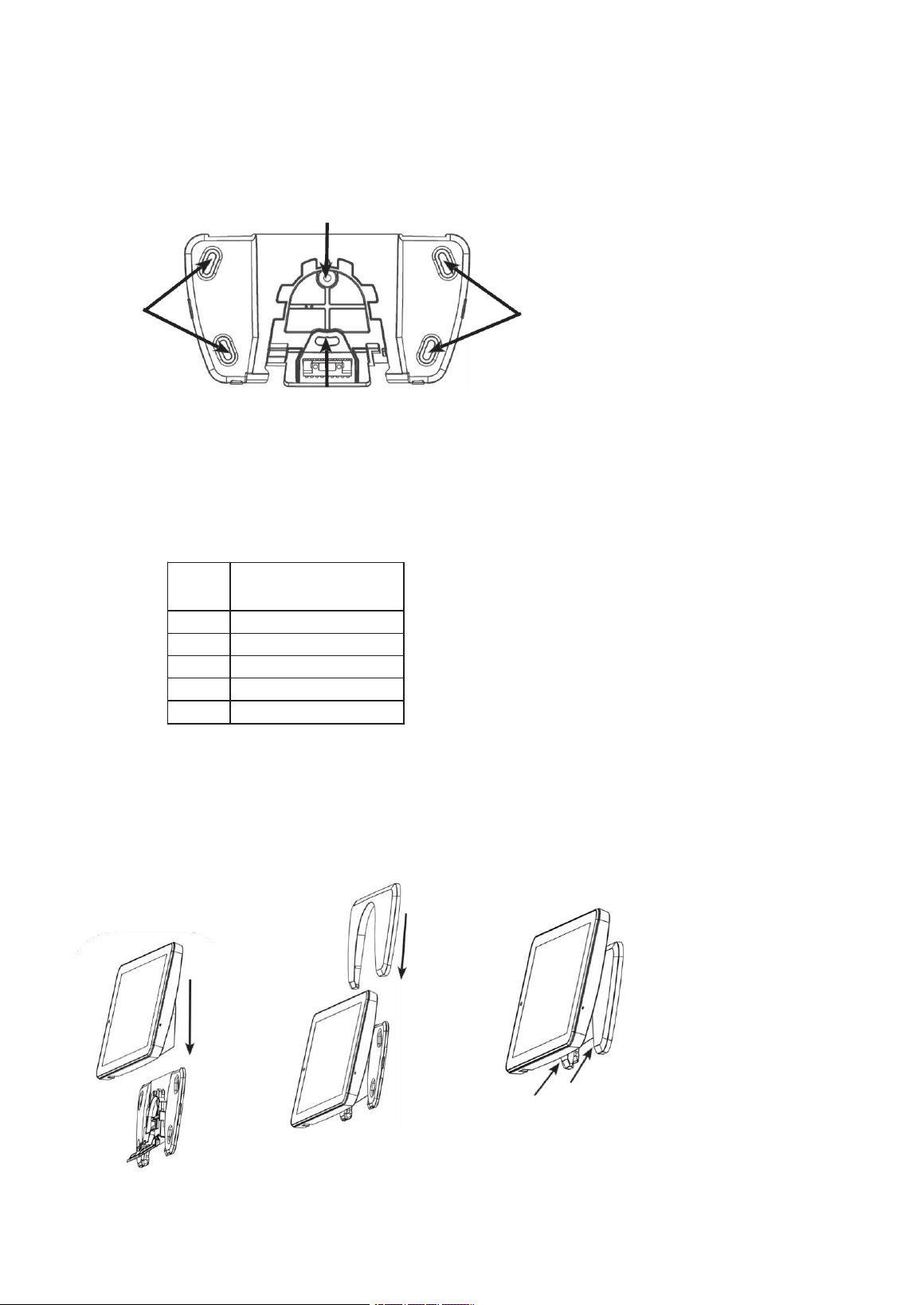
Wall Mount
There are two mounting configurations.
A. Mount it on a support; use the two centered holes located beneath [A].
B. If the unit is not being mounted on a support, use the four holes located at the corners. Insert the wall anchors before tightening the screws in
place [B].
A
B
B
2. There are two methods for connecting power to the touchpad.
A. If you wish to conceal the power cable, you can drill a hole in the wall through one of the four openings on the mounting plate and run the cable
behind the plasterboard to a location with a AC power outlet. Connect one end of the cable to the terminal block located at the back of the
tablet; press the buttons on the terminal block to insert the cable. Connect the other end of the cable to the power supply cables after cutting the
conical connector. YOU MUST USE A PROvided POWER SUPPLY. Power from an existing panel may be insufficient. The cable length
must not exceed the values specified in the instructions.
Wire
From the
cable
Maximum cabling distance
Between Power Source and
Tablet
#24
Up to 21 meters
#22
Up to 30 m
#20
Up to 53 meters
#18
Up to 76 meters
#16
Up to 137 m
B. The barrel connector of the power supply can be directly connected to the rear of the touchpad. The cables can be routed through the cable
channel located on the back of the mounting base. This configuration requires that the connector be properly installed.
Pass it through the mounting base before screwing it onto the wall.
3. Slide the Touchpad
On the plate
Montage: Push it in.
The excess cable should
be routed towards the
wall before installation.
Slip it over the
mounting plate.
4. Place the
Cover behind the
touchpad.
5. Lock the cover
by pressing these
Move it around until it fits
in its proper place.
6. Connect the power supply.
Menu Guide
Main Dashboard
• Favorites – a customizable collection of sensors, Z-Wave® devices, cameras, and scenes that can be easily accessed via the
touchpad panel.
Security
• History – displays the history of events
• Aten – Displays all open, canceled, or problematic zones and peripheral devices.
Note: The zone name and ringtone options can be edited by selecting a specific zone; authentication using a user PIN is required. Zones
and peripheral devices can be renamed via the menu option located to the right of their names.
Name: Zones can also be created, deleted, or edited using the same menu.
Devices
•
Add or remove Z-Wave devices using the "+ Add" or "-Remove" buttons on the app bar.
• Locking and unlocking Z-Wave door locks
•
Configure access codes for the Z-Wave door
•
Turn the Z-Wave lights on and off
• Determine the attenuation level for Z-Wave attenuation switches.
• Open and close garage door hinges using the Z-Wave system
Devices (Continuation)
• Control Z-Wave thermostats
Please refer to the Z-WAVE User Guide for additional information.
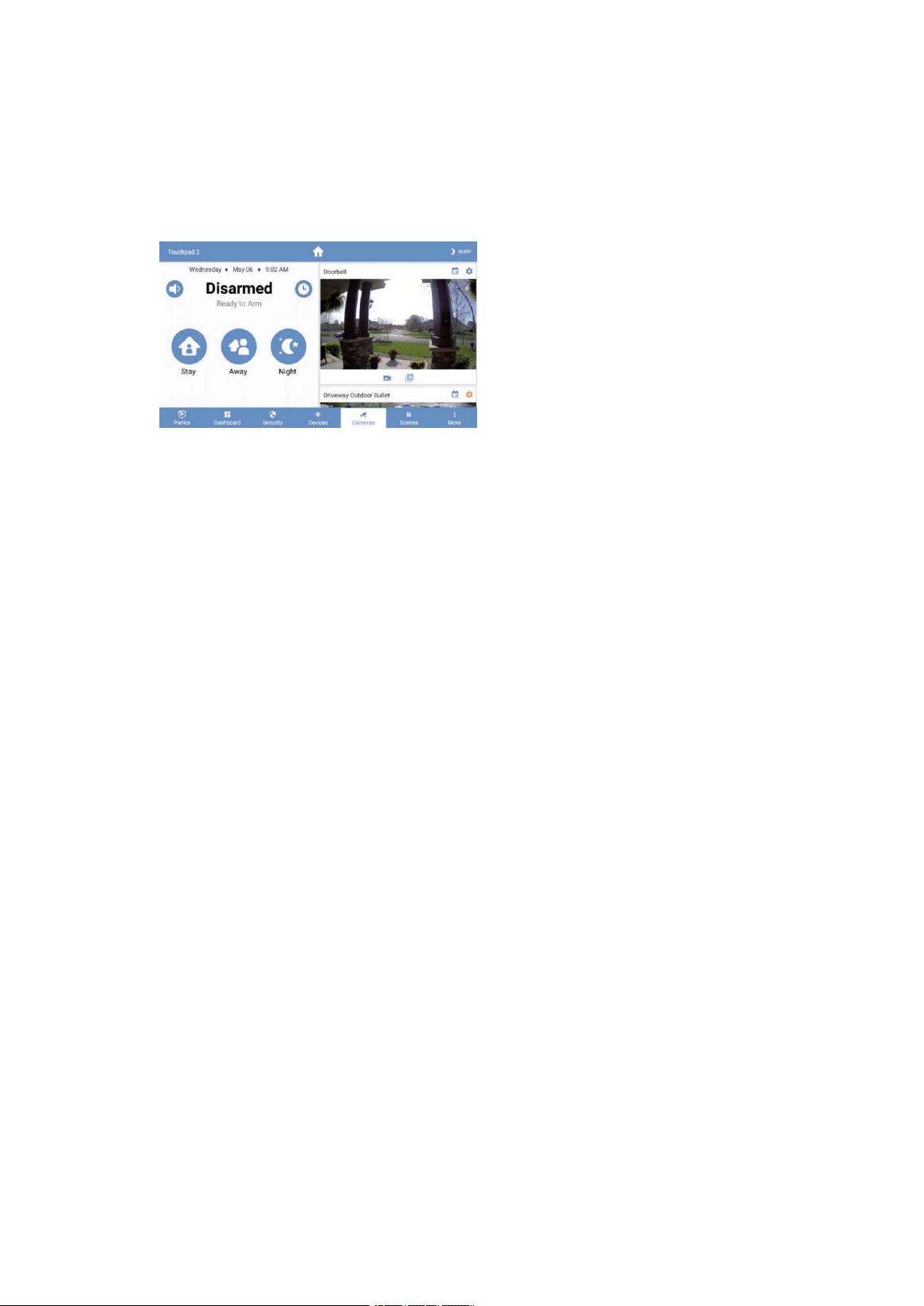
Cameras
•
The cameras can be viewed directly from the touchpad panel. Live views, video clips, and event notifications are supported.
The live camera feed will automatically display when the doorbell button is pressed. Internet access is required for this
functionality.
Scenes
• Creat e scene s from the touch pane l by cl ic ki ng the "+ Add" bu tt on.
• Enable or disable scenes using the toggle button.
• Navigate to the "Edit Scene" page by selecting an item from the list.
•
Change the name of a scene by selecting the name label in the top bar.
•
Modify the scene by adding or removing triggers and actions.
But
–
Six
•
State
• Problems: displays all the issues present in the system
•
If there is a system issue, the panel will emit warning sounds.
• To silence the problem-related beeps for a period of 24 hours:
•
Go to the system page
•
Select the Silence button [top right corner]
•
Smoke detector reset: When it's necessary to reset a smoke detector, the relevant instructions will appear here. Tap and
confirm to perform the reset.
Note: This function is compatible with Napco panels. To reset the smoke sensors on other types of panels, go to Settings-> Panel-> Reset
Sensors.
•
Status Updates: displays all status updates
•
Touchpad
•
Battery: Displays the current battery level and provides information about its charging status.
• Red: Shows the network to which the touchpad panel is connected.
•
MAC Access Point
• Wi-Fi signal strength intensity: must not be lower than 35
• Response Time
• Canal Wi-Fi
•
Touchpad Firmware
•
Touchpad Hardware
•
Touchpad Branding Design: This indicates whether a specific design approach is being applied.
• Firmware updater
•
Android Package
• Serial Series
• Report from FCC/IC
• Activity Duration
But
–
Adjustments
•
Screen
•
Brightness: Adjust the slider bar to change the brightness level.
•
Auto Sleep Screen: When enabled, the touchpad screen will turn off after the scheduled inactivity period.
When disabled, the touchpad displays wallpapers showing the time and device's battery level. Enabling this
feature shows wallpaper images; when disabled, the background remains black.
•
Entry activation feature: When enabled, the screen will turn on during the entry delay period.
• Clean Screen: Ignores touch inputs on the screen for 30 seconds, allowing the user to clean the display.
•
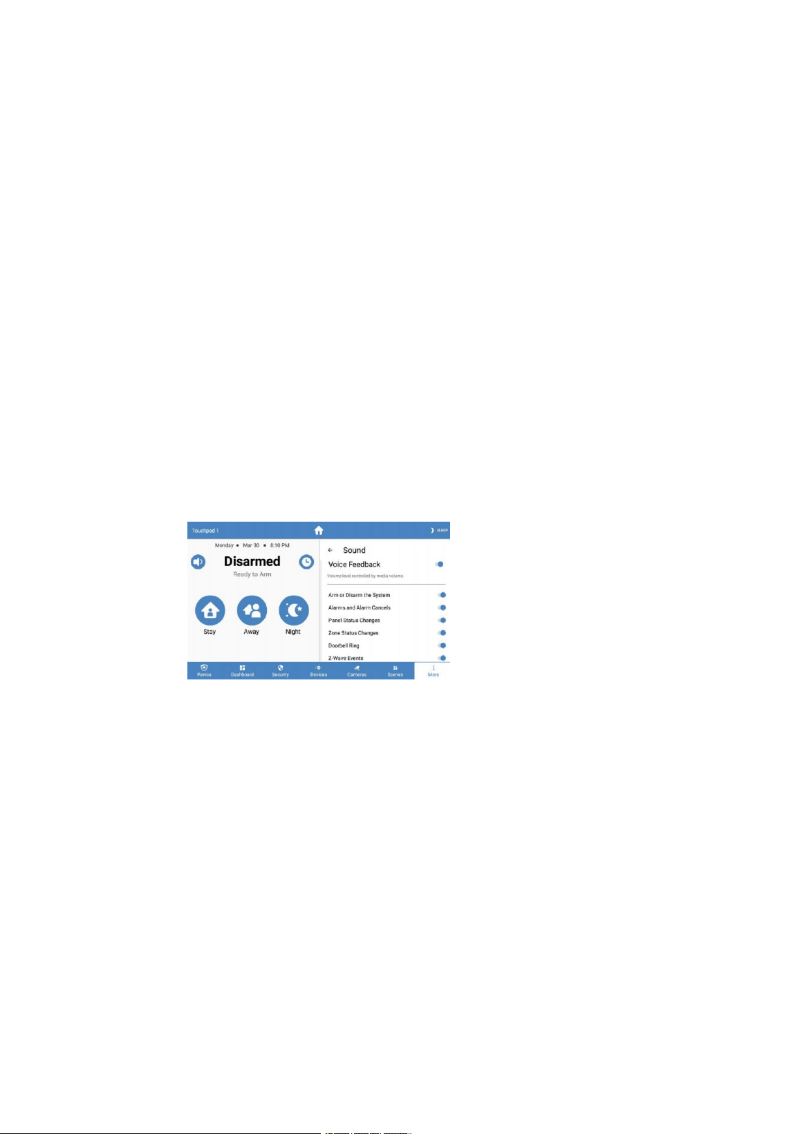
Sound
• Voice response: When enabled, the touchpad provides real-time status updates regarding the system's current state.
The type of updates announced by each touchpad can be configured.
• Volume settings: allows you to control voice comments and the volume of ringtone notifications.
• Key Press Status and Volume
• Security System Status Sounds
• Sound Effect – This option allows you to customize the sound output for each individual touchpad on this system. You
must enable the overall sound setting for the entire touchpad panel; this configuration is used to disable sound
output on any specific touchpad individually.
•
Key press sounds
• Alarm Volume
•
Doorbell tone: Select a customized doorbell notification tone.
• Silence Hours: Set a time period during which the touchpad panel remains silent.
• Touchpad (Enter the code to access)
• Available firmware update: Touchpad updates may be available.
They require internet access to complete the download; this is especially true when there are updates available.
When available, the touchpad requires connection to a local Wi-Fi network to complete the
download and installation. Once the update is finished, the touchpad will resume normal operation.
Note: This option is only visible if there is an update pending download.
• Show Favorites: Displays the Favorites menu, which lists the areas, scenes, and devices that are frequently
used within the panel.
• Show Panics: enables disabling individual panic messages (this option is only visible when using the installer
or distributor).
• Block on the board
• When enabled, only the dashboard menu can be accessed without an access code.
•
When enabled or disabled, no access code is required to navigate outside the control panel.
•
Return to the control panel: Specify the duration of inactivity before the touchpad automatically reverts to its
default state.

• Navigation: Select which items should be accessible using the navigation menu at the bottom.
• Notifications: The ability to enable or disable notifications on the system's general description page.
• Wi-Fi
•
Main network: This is the preferred Wi-Fi network for communicating with Connect+.
Use your local Wi-Fi router. Configuring the main network on your Wi-Fi router allows you to view camera
feeds, receive weather updates, and manage users. Your Connect+ device must be connected to the same
network for this functionality to work.
Security communications.
• Update the network: Connect to your Wi-Fi router to quickly download touchpad updates. This network will only
be used when available.
The update is now available. It is recommended to configure an update network if your primary network uses a
Connect access point; however, if your primary network is your Wi-Fi router, there is no need to configure an
update network.
• Temperature Scale – displays values in °F or °C
•
Alula Cloud
–
You must log in to Alula Cloud as the account owner to use cameras and user administration features.
• Turn Off
•
Panel (Code required to access)
• Timbre Global: Activates or disables the ringtone mode for the sensors.
• Armored Protection: Activates the security panel without entering your access code;
however, the access code is still required to disable the protection.
• Volume of the panel's state
• Wireless Siren Status Volume
• Manage access: Administer device users directly from the touchpad panel (only the account owner can modify user settings;
internet access is required).
• Edit User Installer – Configure the access code and installer password for the system. The installer password can be used
to log in to a Connect+ panel via the Install Connector application.
•
Enter the user's PIN codes into the locks
–
This is required for Z-Wave locks.
Currently, this will remove all existing access codes from every device.
Door locks require the entry of all user PIN codes; these codes will be trimmed down to four digits before being
programmed into the locks.
• UL-compliant mode: When Connect+ is enabled, the device will comply with UL standards.
• Keyboards – List the keyboards on the panel
•
Change the name of the keyboards by selecting an item from the list and holding down the selected key
for 2 seconds.
•
Sensor Reset
–
For sensors that become stuck when activated (such as smoke detectors), you can reset them using
this option.
• Communication Testing Mode
• The touchpad will begin testing the communication connections and display "TESTING".
•
After one minute, the touchpad will display the test result, which will be "GOOD", "NORMAL", or "BAD".
•
If you receive a "Poor" result, try performing the test again from another location.
•
The following table lists the thresholds used to determine the outcome of the test.
•
If any statistic falls within the "deficient range," the test result is "POOR."
•
If none of the statistics fall into the poor range and all statistics fall within the acceptable range, the
test result is "ACCEPTABLE".

•
Panel (continuous)
Statistics
Unit
GOOD
Recommended
Poor
Wi-Fi Signal Strength
dB
About 39
35 to 39
Below 35
Communication Success Rate
%
About 89
85 and 89
Below 85
Average response time
seconds
Below 200
200 to 250
About 250
• Check for updates – This will instruct the system panel to search for updates.
•
Z-Wave
• Join/leave another Z-Wave network – The panel can be set to "inclusion" mode.
Or use the "Exclusion Mode" option to allow the device to connect to or disconnect from existing
Z-Wave networks.
•
Smooth Restart
–
A smooth restart will reset the Z-Wave driver software; all Z-Wave devices will remain
registered.
• Complete Restoration – This command sets the Z-Wave Connect+ module back to its default state. Warning:
Performing this operation will remove all Z-Wave devices connected to this Z-Wave controller. To re-add them,
You must first exclude them, and then reinclude them.
**Please refer to the Z-WAVE User Guide for additional information.**
• About: Provides information regarding the hardware and software installed on the panel.
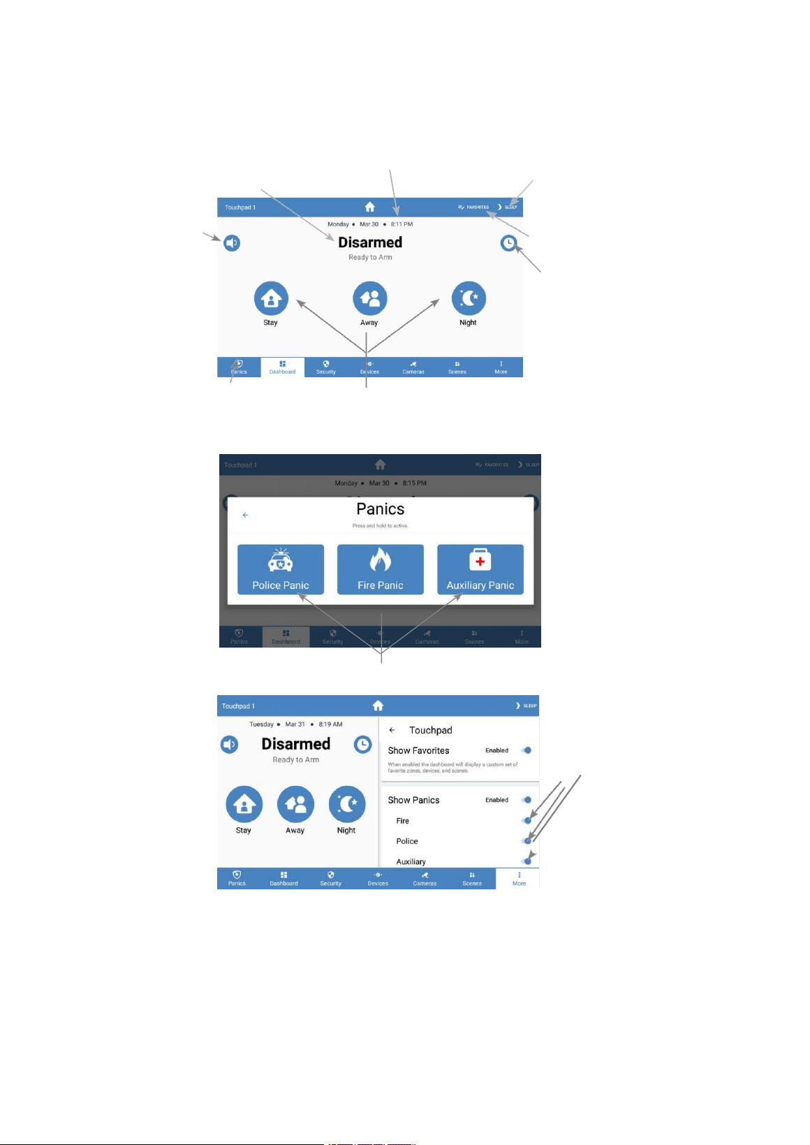
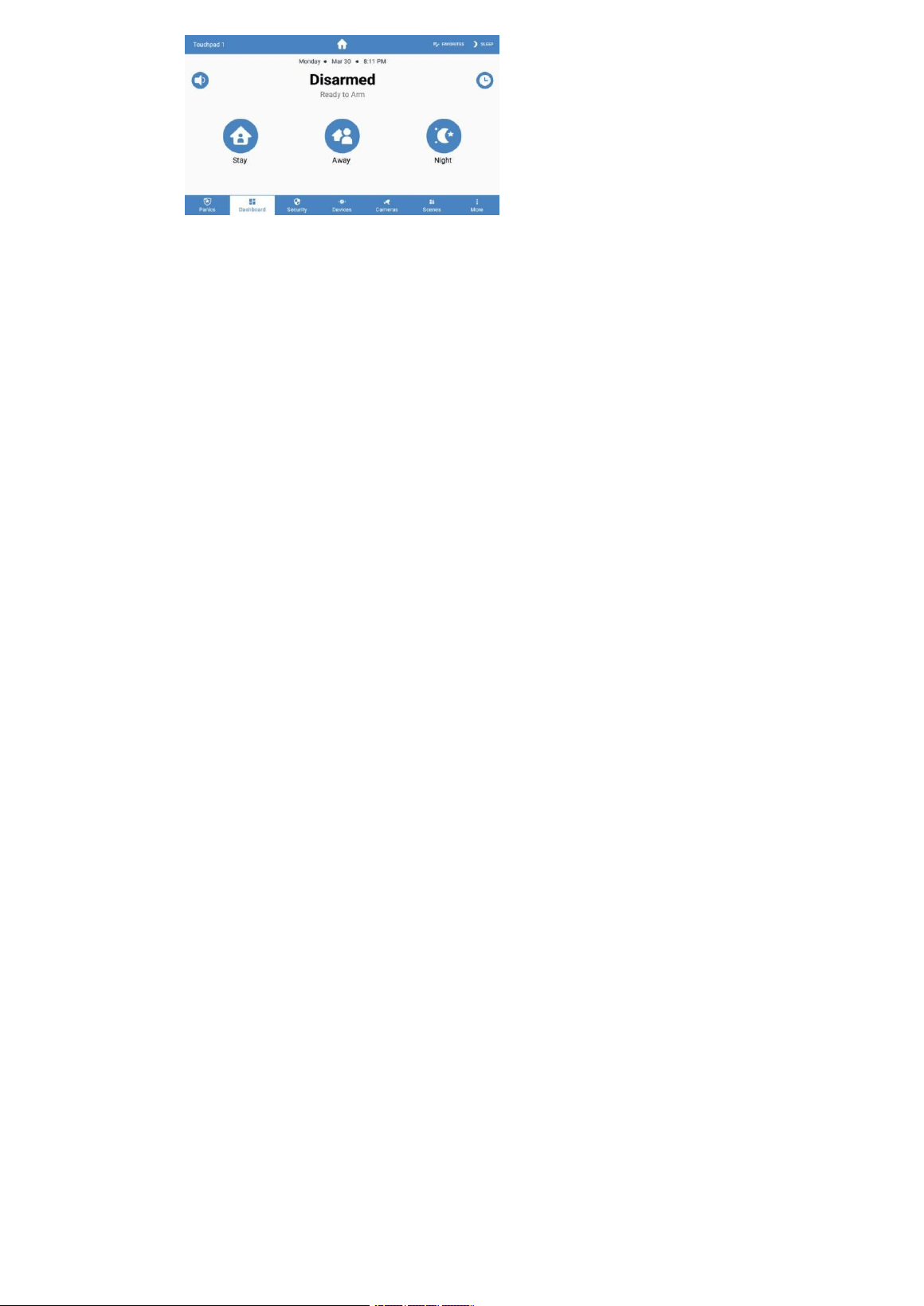
Functions of the Home Screen*
The time zone can be set
The title indicates the status of the panel, such as "Disassembled"
or "Assembled at Home".
Touch for Touch for
Silence the beeps during operation.
The
Arms/Disarm
O
Click to disable entry delay.
A
Click to view the Panic options.
Press one of the assembly buttons to assemble the panel.
Panic Features*
A
The device remains under constant pressure to activate the police alarm system, trigger fire alarms, or activate the auxiliary alarm.
Activate/Deactivate individual alarms
These functions were taken from Connect; their specific details may vary depending on the particular panel in use.
Touch to turn off the
touchpad screen
Click to edit favorite areas
and scenes.
Cameras
Configure in Alula Connect
Professional Tips
When the touchpad is connected to the system, the Connect+ interface remains available for use.
Use during power outages. The Connect+ is powered by a battery-backed system; however, if the touchpad is connected only to the local Wi
-Fi network, Alula recommends...
All network devices, including the Wi-Fi access point, should be connected to a suitable UPS (Uninterruptible Power Supply) to
ensure the system remains operational during any power outage.
Every effort is made to ensure that touchpad panels come with sufficient power to start up. However, there may occasionally be instances
where the touchpad fails to turn on upon connection to the power source and requires additional steps to activate it.
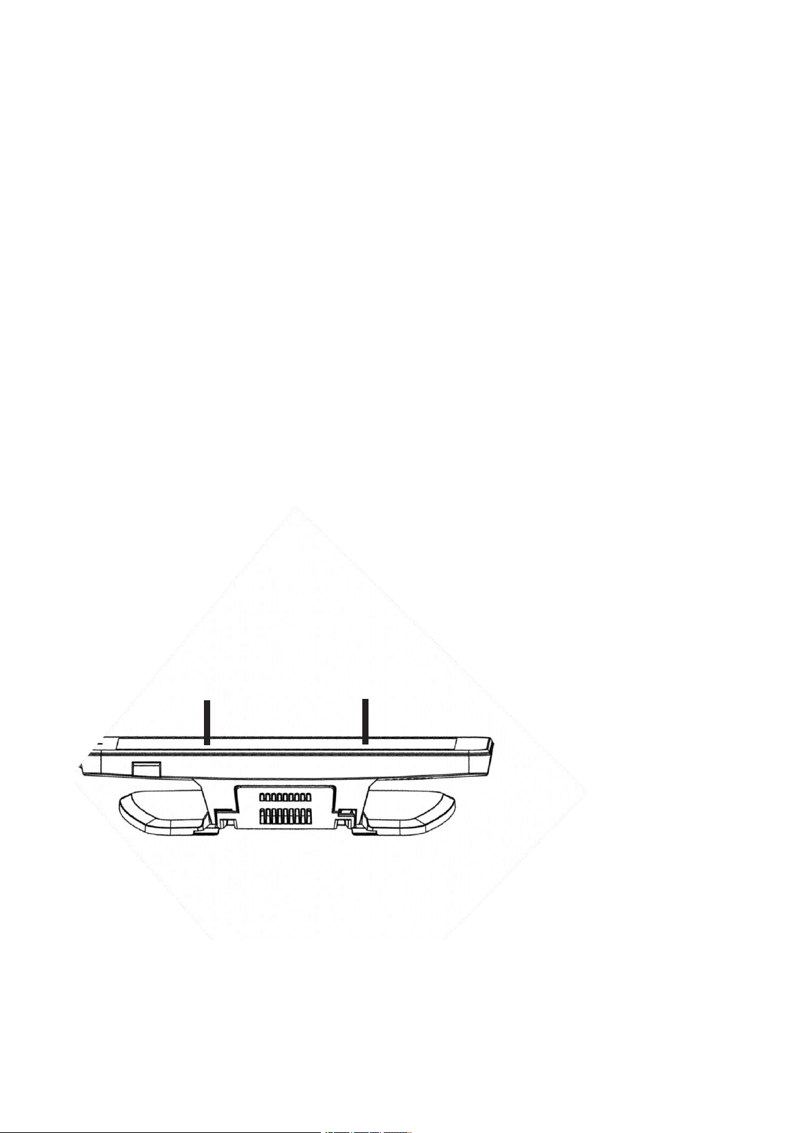
1. Ensure that the touchpad has been connected to a properly functioning power source for at least 5 minutes.
2. Locate the hole on the top of the tablet; this hole conceals the power button. Using a clip, press the button
for 20 seconds.
3. Wait 5 seconds.
4. Press and hold the power button again for 2 or 3 seconds.
5. If the touchpad does not turn on after following these steps, check the power supply connection and keep the touchpad connected for at
least 20 minutes. Repeat the above steps. Contact technical support if the problem persists.
Insert any additional cables into the wall before sliding the touchpad panel onto its place.
Use a mounting plate to ensure that the cables do not get caught. If there are no holes already present, drill a hole in the wall corresponding
to one of the four openings on the mounting plate.
The touchpad screen turns off automatically after a period of inactivity.
The automatic suspension mode of the watchback display activates upon power-on, when the screen is touched, or in certain alarm
situations. The display can also be manually turned off by pressing the "suspend" button.
To cancel the registration of the touchpad, navigate to the "Configure" menu and then to the section titled "Panel." Set the panel to wireless
recording mode.
Press the "Cancel Registration" button on the touchscreen panel. Note: The "Cancel Registration" button appears on the touchscreen only when
the panel is in registration mode.
You can add weather information to the touchpad if internet access is available. To do so, scroll down from the top of the screen and select "Add
Weather". Once configured, real-time weather data will appear in the dropdown menu or on the system's general overview screen.
The automatic suspension screen configuration is disabled
To remove the vanity cover, insert a flat-end screwdriver into both points shown below and turn the screwdriver.
A A A A
Specifications
Physical Specifications
Wall Dimensions
Tablecloth
Weight
Wood opening
Wall anchoring hole for
mounting brackets
4.27 inches [10.84 cm]
×
7.42 inches [18.85 cm]
×
1.60 inches
[4.06 cm]
4.58 in [11.64 cm]
×
7.42 in [18.85 cm]
×
6.63 in [16.84 cm];
Weight: 1.29 lbs [585 g]
Ø 1/8 inch [3 mm]
Ø 3/16 inch [4.7 mm]
#6 screws & 4 wall anchors (included)
Environmental Specifications
Temperature | Operating
Temperature | Maximum Humidity
| Maximum
32
°
F to 120
°
F (0
°
C to 49
°
C)
85% non-condensing relative humidity
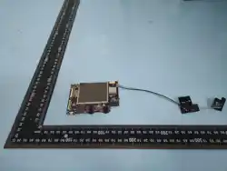
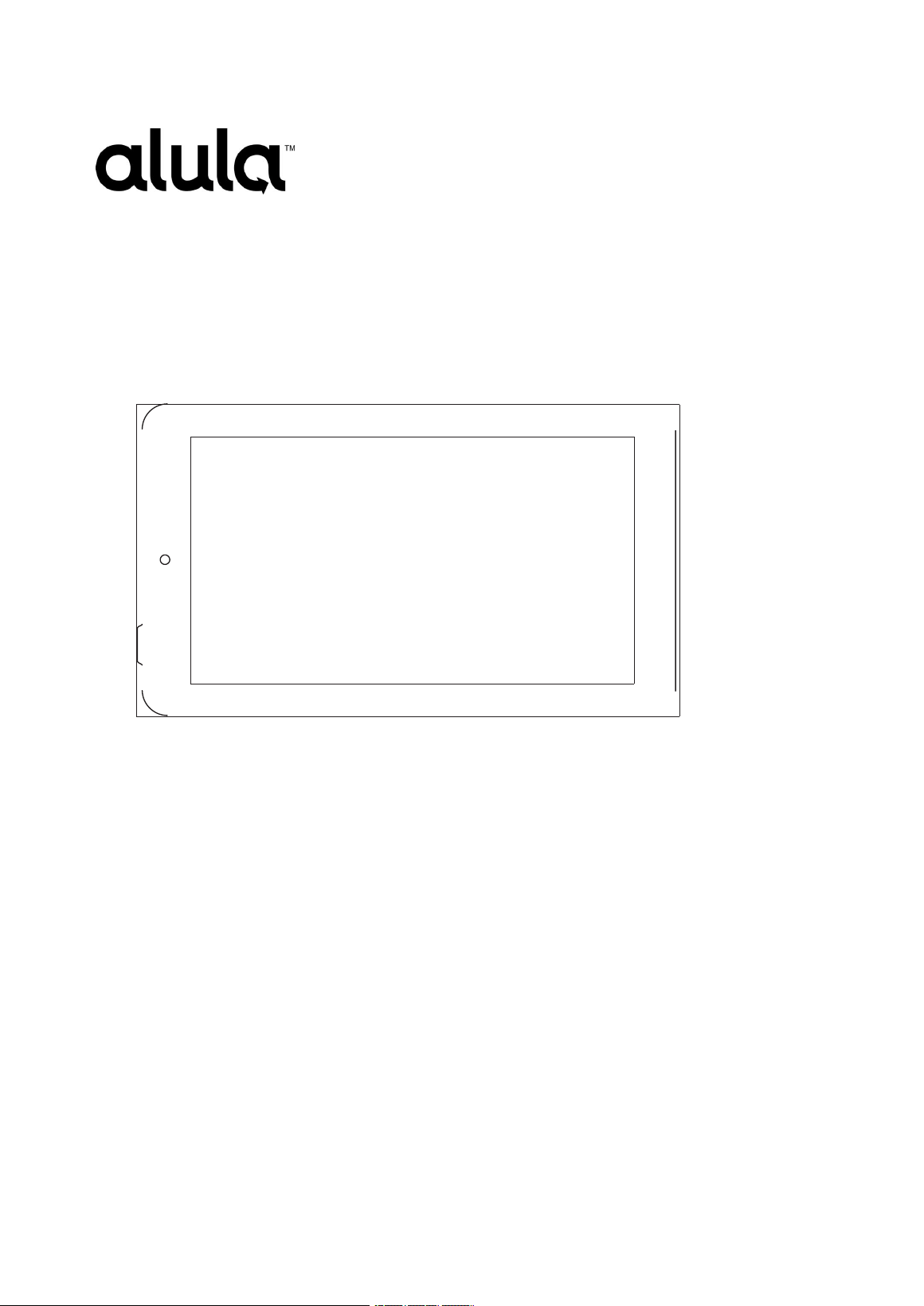
Device Specifications
Input
Transformer
Output
Part Parte
Wire Gauge for Terminal Wireless
Range
Resolution
Screen Size
100–240 VAC, 50/60 Hz, 0.5
A, 12 V DC, 1 A
RE012-6
16–24 AWG
~91 m in line of sight
1024 x 600 pixels
7 inches diagonally
Certifications
RE667-Pro
FCC, IC, RCM
Specifications subject to change without prior notice.
ISED Caution:
- English:
This device contains licence-exempt transmitter(s)/receiver(s)
that comply with Innovation, Science and Economic
Development Canada's licence-exempt RSS(S).
Operation is subject to the following two conditions:
(1) This device may not cause interference.
(2) This device must accept any interference, including
interference that may cause undesired operation of the
device.
Any changes or modifications not expressly approved by the
party responsible for compliance could void the user's
authority to operate the equipment.
The equipment complies with ISED Radiation exposure
limit set forth for uncontrolled environment,
without restriction.
-French:
Cet appareil contient des émetteurs / récepteurs exemptés de
licence conformes aux RSS(RSS) d'Innovation, Sciences et
Développement économique Canada. Le fonctionnement est
soumis aux deux conditions suivantes:
(1) Cet appareil ne doit pas causer d'interférences.
(2) Cet appareil doit accepter toutes les interf
é
rences, y
compris celles susceptibles de provoquer un fonctionnement
ind
é
sirable de l'appareil.
Tout changement ou modification non express
é
ment approuv
é
par la partie responsable de la conformit
é
pourrait annuler
l'autorité de l'utilisateur à utiliser l'équipement.
L'équipement est conforme à la limite d'exposition aux radiations
de la ISED établie pour un environnement non contrôlé,
sans restriction.
Business Brands
Alula and Connect+ are commercial brands owned by...
Alula Holdings, LLC: Android is a commercial trademark of Alula
Holdings, LLC.
Google LLC. Z-Wave is a registered trademark of Silicon Labs;
Wi-Fi is a registered trademark of Wi-Fi Technologies, Inc.
Alliance.
FCC Warning (Spanish
–
See the English version
below)
This equipment has been tested and meets all required specifications.
Designed for a Class B digital device.
Compliance with Part 15 of the FCC Standards.
These limits are designed to provide protection.
Reasonable measures against interference that is harmful to the
system within an installed setup
Residential installation.

This equipment generates, utilizes, and can emit energy or power.
Radio frequency technology; however, if it is not installed and
used in accordance with the specified guidelines...
If not followed properly, these instructions may cause harmful
interference.
Radio communications. However, there is no guarantee of
reliability or stability in such transmissions.
To ensure that no interference occurs within the installation.
It has been determined that this equipment causes harmful
interference.
The reception quality of radio or television, which can be
determined
When turning the equipment on and off, it is recommended that
the user follow the appropriate procedures.
that attempts to correct the interference using one or more of the
available methods
Following these steps:
• Reorient or relocate the receiving antenna.
•
Increase the distance between the equipment and the receiver.
Connect the device to a power outlet on a different electrical
circuit.
The component to which the receiver is connected.
• Consult your distributor or an experienced
radio/TV technician for assistance.
This device complies with Part 15 of the FCC regulations.
The operation is subject to the following two conditions:
(1) This device must not cause harmful interference.
(2) This device must be able to withstand any interference.
It should be able to receive signals, including those that
may cause unwanted interference in its operation.
Note: Any changes or modifications to this device
which has not been explicitly approved by the manufacturer.
This grants the user authority to operate this device.
The device has been evaluated to ensure it meets all required
specifications.
General information about RF exposure: The device can be used in...
Unrestricted portable display conditions.
47-00018 • Rev. D • 2023-07-03
Technical Support Line
•
(888) 88-ALULA
•
(888) 882-5852
Underline

FCC Warning
This device complies with part 15 of the FCC Rucontain the cables. Operation is subject to the following two
conditions: (1) This device may not cause harmful interference, and (2) this device must accept any interference
received, including interference that may cause undesired operation.
Note: This equipment has been tested and found to comply with the limits for a Class B digital device, pursuant
to part 15 of the FCC Rucontain the cables. These limits are designed to provide reasonable protection against
harmful interference in a residential installation. This
Equipment generates, uses, and may emit radio frequency energy; if not installed or operated in accordance
with the instructions, it can cause harmful interference to radio communications.
However, there is no guarantee that interference will not occur in a particular installation. If this equipment does
cause harmful interference to radio or television reception, which can be determined by turning the equipment off
and on, the user is encouraged to try to correct the interference by one or more of the following measures:
—Reorient or relocate the receiving antenna
Increase the distance between the equipment and the receiver.
Connect the equipment to an outlet on a circuit different from the one to which the receiver is connected.
—Consult a dealer or an experienced radio/TV technician for assistance.
Note: The Grantee is not responsible for any changes or modifications that are not explicitly specified.
Approved by the party responsible for compliance; such modifications may invalidate the user's authority to operate
the equipment.
The device has been evaluated to meet general RF exposure requirements.
This equipment complies with FCC's RF radiation exposure limits set forth for an uncon- trolled environment.
This device and its antenna(s) must not be co-located or conjunction with any other antenna or transmitter.
General information about RF exposure: The device can be used in Unrestricted portable display conditions.