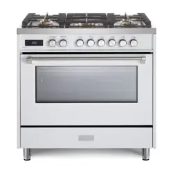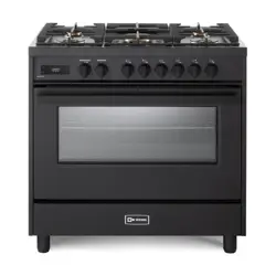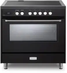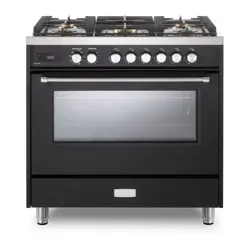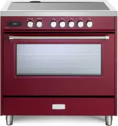
DOUBLE OVEN ELECTRIC RANGE
for residential use only
Model(s): VUFSEE365D...
INSTALLATION INSTRUCTIONS
IMPORTANT - PLEASE READ AND FOLLOW
• Before beginning, please read these instructions completely and carefully.
• Do not remove permanently axed labels, warnings, or plates from the product. This may
void the warranty.
• Please observe all local and national codes and ordinances.
• Please ensure that this product is properly grounded.
• The installer should leave these instructions with the consumer who should retain
for local inspector’s use and for future reference.
• IN CANADA: The electrical plug should always be accessible.
Electrical installation must be in accordance with the National Electrical Code, ANSI/NFPA70
- latest edition and/or local codes.
IN CANADA: Electrical installation must be in accordance with the current CSA C22.1
Canadian Electrical Codes Part 1 and/or local codes.
R
FOR INSTALLER ONLY
THIS RANGE IS FOR RESIDENTIAL USE ONLY
Some models are supplied with a protective lm on steel and aluminum parts.
This lm must be removed before installing/using the appliance.

22
TABLE OF CONTENTS
CONTENTS Page Number
Important Safety Precautions & Recommendations . . . . . . . . . . . . . . . . . . . . . . . . . . . . . . . . . . . . . . . . . . . . . . . . . .
Installation . . . . . . . . . . . . . . . . . . . . . . . . . . . . . . . . . . . . . . . . . . . . . . . . . . . . . . . . . . . . . . . . . . . . . . . . . . . . . . . . . .
Electrical Connection . . . . . . . . . . . . . . . . . . . . . . . . . . . . . . . . . . . . . . . . . . . . . . . . . . . . . . . . . . . . . . . . . . . . . . . . .
3 - 5
6 - 11
12 - 15
33
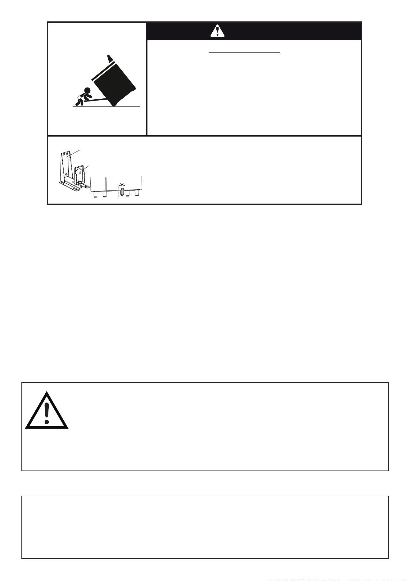
WARNING
- Slide range back so bolt head, on the adjustable bracket assembly, is
--under anti-tip bracket.
- Look for the anti-tip bracket securely attached to oor or wall.
- See installation instructions for details.
- Look for the adjustable bracket assembly securely attached to
--the back of the range.
- Slide range forward.
To verify the anti-tip bracket is installed and engaged:
Tip-Over Hazard
Anti-tip bracket
Adjustable bracket
assembly to be xed to
the back of the range
A child or adult can tip the range and be killed.
Install anti-tip device to range and/or structure per installation
instructions.
Engage the range to the anti-tip device Installed to the structure.
Re-engage anti-tip device if range is moved.
Failure to follow these instructions can result in death or serious
burns to children and adults.
This appliance is designed and manufactured solely for the cooking of domestic (household)
food and in not suitable for any non domestic application and therefore should not be used in a
commercial environment.
The appliance warranty will be void if the appliance is used within a non domestic environment i.e.
a semi commercial, commercial or communal environment.
WARNING: This product can expose you to chemicals including
formaldehyde, which is known to the State of California to cause cancer,
and lead, which is known to the State of California to cause birth defects or other
reproductive harm. For more information go to www. P65Warnings.ca.gov.
44
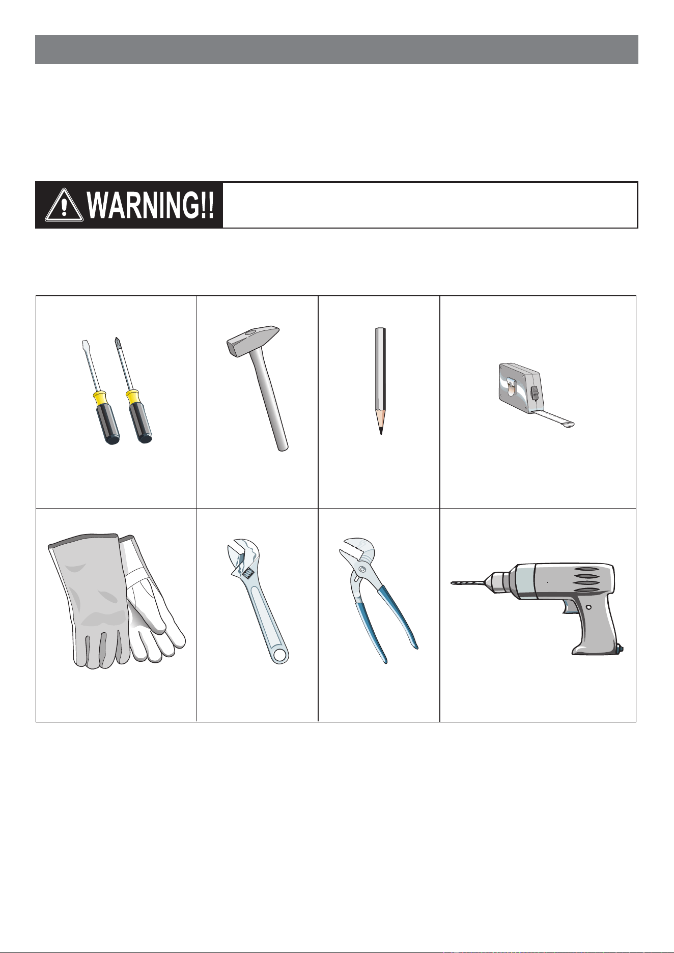
TOOLS NEEDED FOR INSTALLATION (NOT SUPPLIED WITH THE APPLIANCE)
IMPORTANT: The use of suitable protective clothing/gloves is
recommended when handling or installing this appliance.
WARNING!
THIS APPLIANCE MUST BE INSTALLED BY A QUALIFIED INSTALLER.
Installation must conform with local codes.
Improper installation, adjustment, alteration, services, or maintenance can cause injury or property damage.
Consult a qualied installer or a service agent.
INSTALLATION INSTRUCTIONS
Screwdriver
Tape
measurePencil
Adjustable
pliers
Adjustable
wrench
Suitable protective
gloves Drill
Hammer

55
GENERAL INFORMATION
1. WARNING!!
This appliance shall not be used for space heating. This
information is based on safety considerations.
2. AlI openings in the wall behind the appliance and in the oor
under the appliance shall be sealed.
3. Keep appliance area clear and free from combustible
materials, gasoline, and other ammable vapors.
4. Do not obstruct the ow of ventilation air.
5. Disconnect the electrical supply to the appliance before
servicing.
6. When removing appliance for cleaning and/or service;
A. Disconnect AC power supply.
B. Carefully remove the range by pulling outward.
CAUTION: Range is heavy; use care in handling.
7. Electrical Requirement
Electrical installation should comply with national and local
codes.
8. The misuse of oven door (e.g. stepping, sitting, or leaning on
them) can result in potential hazards and/or injuries.
9. When installing or removing the range for service, a rolling lift
jack should be used. Do not push against any of the edges of
the range in an attempt to slide it into or out of the installation.
Pushing or pulling a range (rather than using a lift jack) also
increases the possibility of bending the leg spindles or the
internal coupling connectors.
WARNING!!
ELECTRICAL GROUNDING INSTRUCTIONS
The range must be electrically grounded in accordance with
local codes or, in the absence of local codes, with the National
Electrical Code, ANSI/NFPA No. 70-latest edition, in Canada
Canadian Electrical Code.
Installation should be made by a Iicensed electrician.
FOR PERSONAL SAFETY, THIS APPLIANCE MUST BE
PROPERLY GROUNDED.
If an external electrical source is utilized, the installation must
be electrically grounded in accordance with local codes or, in
the absence of local codes, with the national Electrical Code,
ANSI/NFPA 70.
IN CANADA: This appliance is equipped with a four-prong
grounding plug (NEMA 14-50P) for your protection against shock
hazard and should be plugged directly into a properly grounded
socket.
Do not under any circumstances cut or remove the fourth
(ground) prong from the power plug.
REPLACEMENT PARTS
Only authorized replacement parts may be used in performing
service on the range. Replacement parts are available from factory
authorized parts distributors. Contact the nearest parts distributor
in your area.
66
PROXIMITY TO SIDE CABINETS
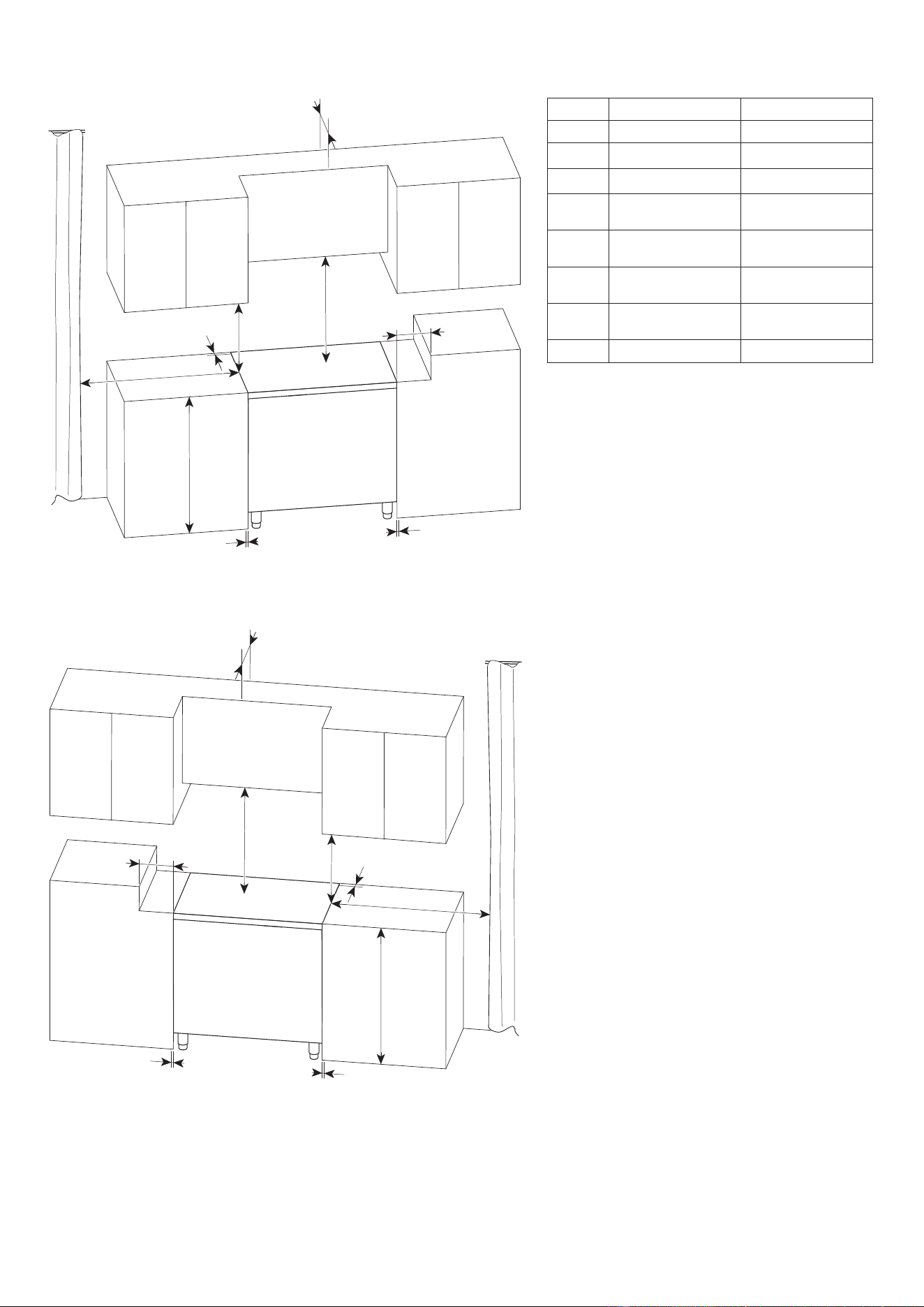
1. This range may be installed directly adjacent to existing 36”
(914 mm) high base cabinets.
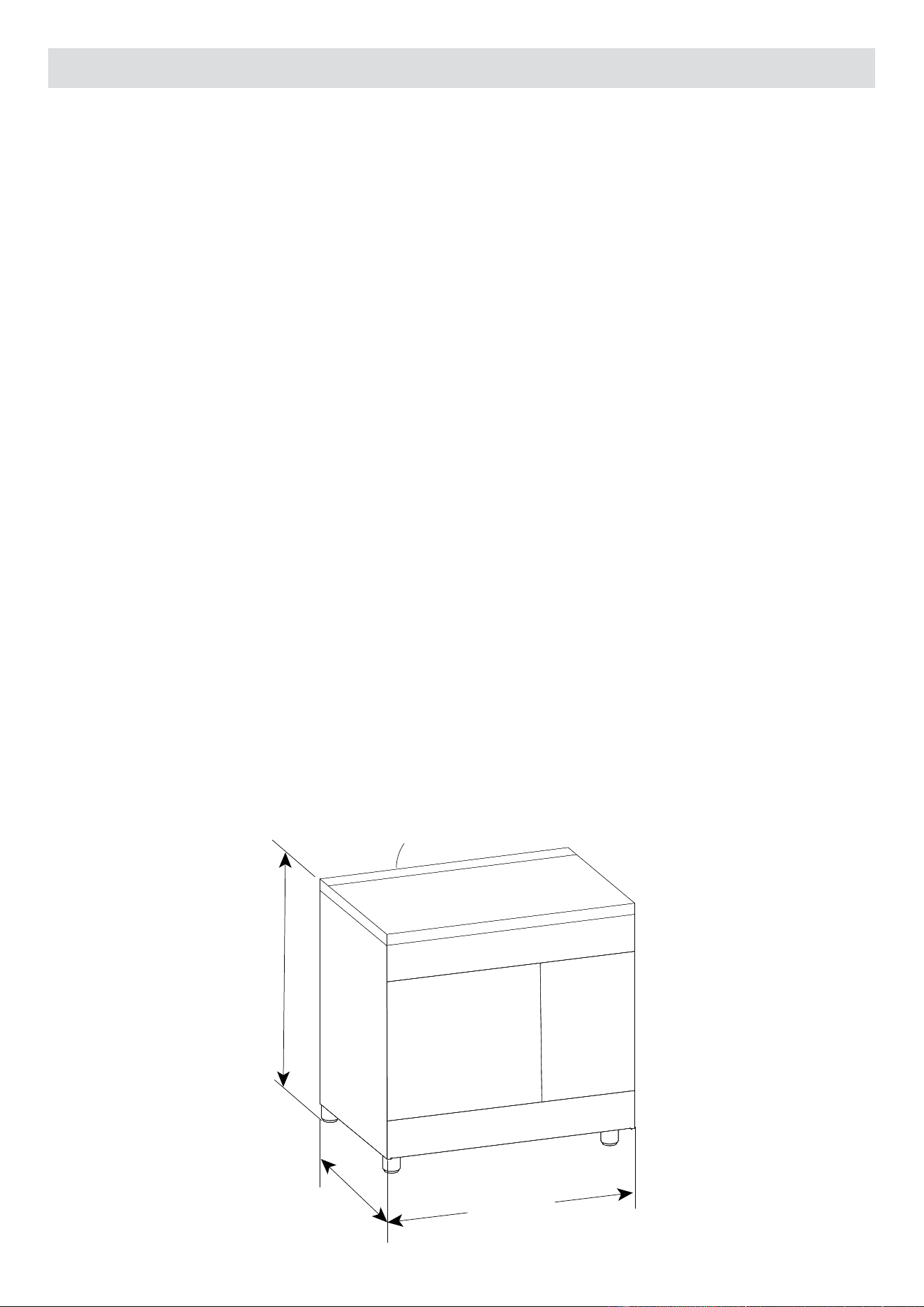
Range dimensions:
• width: 35” 7/8 (911 mm) (width of cabinetry opening: 36”,
914 mm)
• depth: 25” 1/4 (641 mm)
• height: MIN 35” 1/8 (892.5 mm) - MAX 37” 3/32
(942.5 mm)
• backguard (height): level with cooktop
NOTE: The backguard is already fitted on the appliance.
IT IS MANDATORY TO INSTALL AND USE THE
APPLIANCE WITH THE BACKGUARD CORRECTLY
IN PLACE.
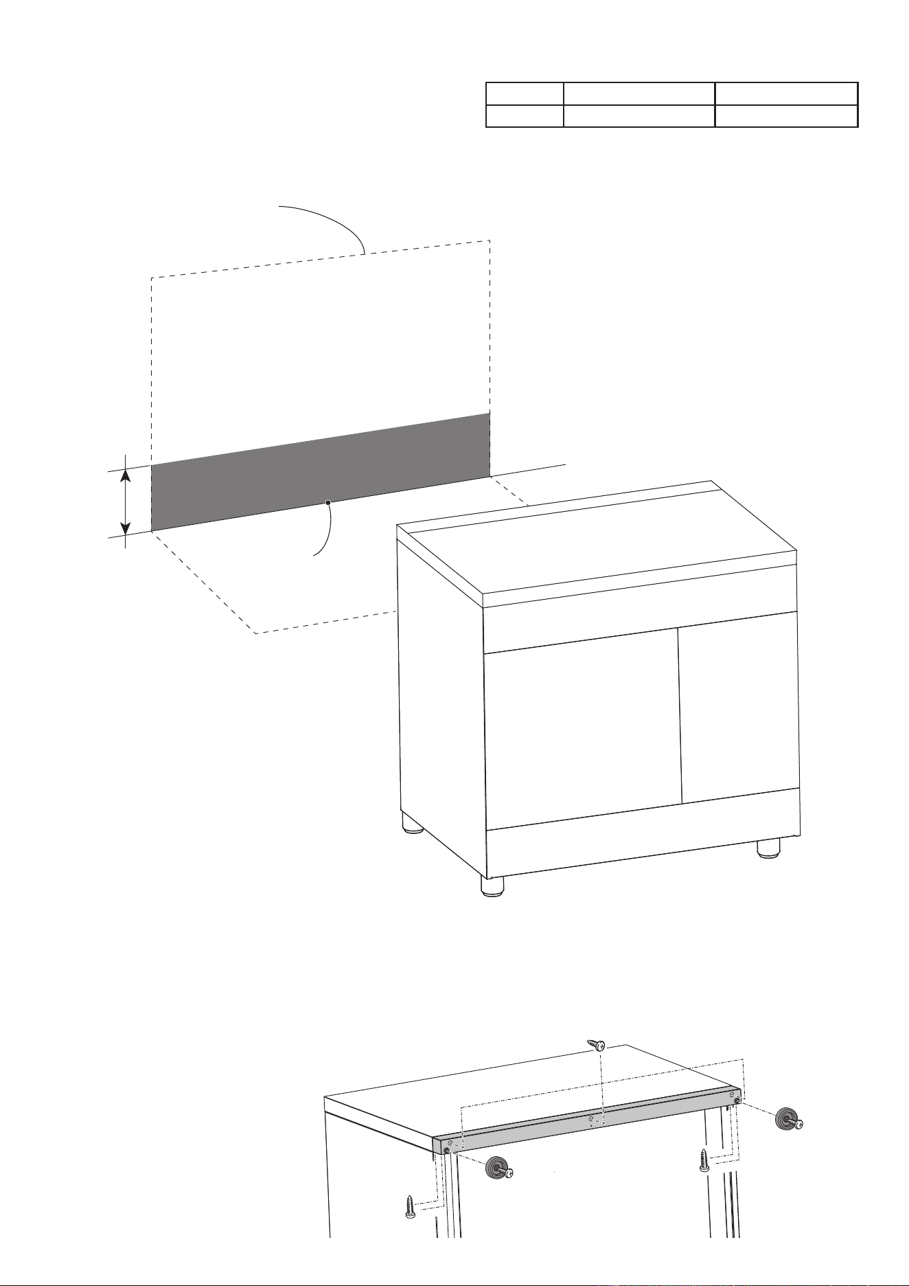
Grounded outlet: The grounded outlet should be located
from the left to the right side of the range; from 8” 1/4 (210
mm) to 10” 1/4 (260 mm) [depending on feet regulation] from
the oor.
IN CANADA: The electric cord with 4-prong ground plug
(NEMA 14-50P) has a length of 72” (1830 mm).
2. Range may be installed with zero clearance adjacent to
(against) combustible construction at the rear and on the
sides below the cooktop. The range CANNOT be installed
directly adjacent to sidewalls, tall cabinets, tall appliances,
or other side vertical surfaces above the 36” (914 mm) high
countertop. There must be a minimum of 2” (50 mm) side
clearance from the range to such combustible surfaces TO
THE LEFT and TO THE RIGHT above the 36” (914 mm) high
countertop.
3. The maximum upper cabinet depth recommended is 13”
(330 mm). A ventilation hood or a wall cabinet above the
range must be a minimum of 24” (610 mm) or 30” (762 mm)
(see also “Additional information about minimum clearance
from cooking surface to overhead cabinet or ventilation
hood” here below) above the cooking surface, for a width of
minimum 36” (914 mm): it has to be centered with the range.
Side wall cabinets above the range must be a minimum of
18” (457 mm) above the countertop.
Additional information about minimum clearance from
cooking surface to overhead cabinet or ventilation hood:
• 30” (762 mm), overhead cabinet centered above the cooktop
(combustible/unprotected) (see also notes #1, #2)
• 24” (610 mm), overhead cabinet centered above the cooktop
(non-combustible/protected) (see also notes #1, #2)
• 24” (610 mm), ventilation hood centered above the cooking
surface (see also note #3)
Note #1
To eliminate the risk of burns or re by reaching over heated surface
units, cabinet storage space located above the surface units
should be avoided. If cabinet storage is to be provided, the risk can
be reduced by installing a rangehood that projects horizontally a
minimum of 5” (127mm) beyond the bottom of the cabinets.
Note #2
30” (762) minimum clearance between the top of the cooking
surface and the bottom of an unprotected wood or metal cabinet;
or 24” (610mm) minimum when bottom of wood or metal cabinet
is protected by not less than 1/4” thick ame retardant millboard
covered with not less than No. 28 MSG sheet steel, 0.015” (0.4
mm) thick stainless steel, 0.024” (0.6 mm) thick aluminum, or
0.020” (0.5 mm) thick copper.
Note #3
Refer to local/national codes for ventilation requirements.
1. INSTALLATION
Fig. 1.1
35” 7/8
(911 mm)
Backguard
25” 1/4
(641 mm)
MIN 35” 1/8 (892.5 mm)
MAX 37” 3/32 (942.5 mm)
77
Fig. 1.3
ELECTRICAL CONNECTION
Fig. 1.2
Dotted line showing the
position of the range
when installed
Area for
ELECTRICAL
connection
A
Ref. inch mm
A 8” 1/4 - 10” 1/4 (*) 210 - 260 (*)
(*): Depending on feet regulation
BACKGUARD
• The backguard is already tted to the appliance.
• It is mandatory to install and use the appliance with the
backguard correctly in place (g. 1.3).
x2
x1
x1
x2
x3
88
PROXIMITY TO SIDE CABINETS
Fig. 1.4b
Fig. 1.4a
Ref. inch mm
A 0” 0
B 36” (*) 914 (*)
C 2” 50
D
24” or 30”
minimum (**)
610 or 762
minimum (**)
E
18”
minimum
457
minimum
F
13”
maximum
330
maximum
G
20”
minimum
500
minimum
H 0” 0
A
C
A
B
G
E
D
F
A
A
B
G
E
D
F
C
H
H
(*) Maximum height of cabinetry immediately
adjacent to the range (from oor to countertop).
Depending on the height of the feet adjustment.
The cooking surface must sit ush or above
countertop level.
(**) See also “Additional information about minimum
clearance from cooking surface to overhead
cabinet or ventilation hood” at page no.6.
99
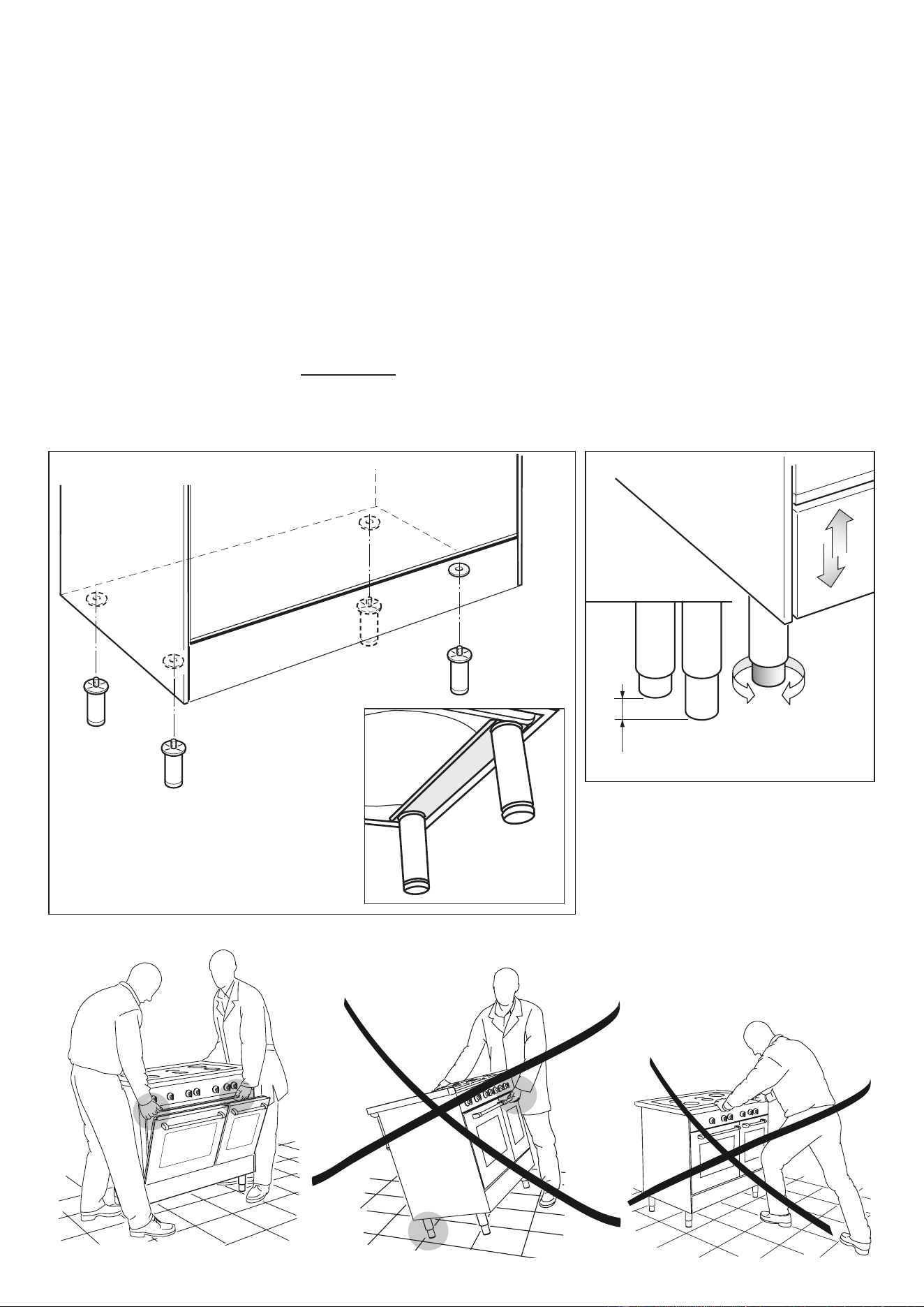
FITTING THE ADJUSTABLE FEET
The adjustable feet must be fitted to the base of the cooker before use.
Fit the 4 legs by screwing them tight into the support base as shown in pictures 1.5 - 1.6.
ATTENTION: Most important! Pay special attention not to damage the range during this operation.
IMPORTANT: It is mandatory to install and use the range with all the 4 adjustable feet correctly in place.
LEVELLING THE COOKER
The cooker may be levelled by screwing the lower ends of the feet IN or OUT (fig. 1.7).
It is important to observe the directions of figure 1.7.
MOVING THE COOKER
WARNING:
When raising cooker to upright position always ensure two people carry out this manoeuvre to prevent damage to the adjustable feet
(fig. 1.8a).
WARNING:
Be careful: do not lift the cooker by the door handle when raising to the upright position (fig. 1.8b).
WARNING:
When moving cooker to its final position
DO NOT DRAG
(fig. 1.8c).
Lift feet clear of floor (fig. 1.8a).
+ 1" 31/32
+ 50 mm
0 mm
0"
Fig. 1.5
Fig. 1.6
Fig. 1.7
Fig. 1.8a Fig. 1.8b Fig. 1.8c
1010
INSTALLING THE ANTI-TIP BRACKET
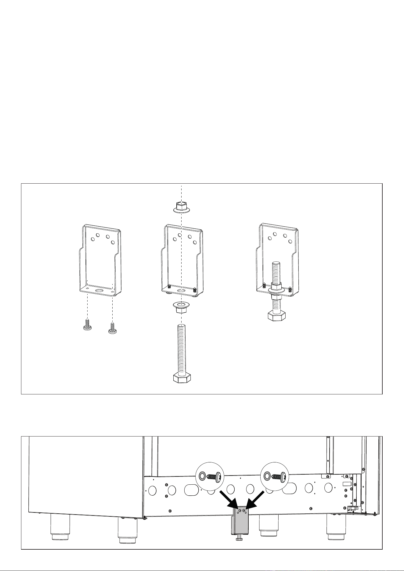
The anti-tip bracket has two components (gs. 1.9, 1.11):
• the adjustable bracket
• the stability bracket
IMPORTANT!
You must install both parts of the anti-tip bracket and ensure they are properly tted together to prevent the range from tipping.
TO FIT THE ANTI-TIP BRACKET:
1. Fix the two supplied short screws to the left and right side of the adjustable bracket (g. 1.9).
2. Thread the bolt through the adjustable bracket and x in place using the two supplied nuts (g. 1.9). Ensure the nuts are well
tightened.
3. Fix the adjustable bracket to the back of the range using the two supplied screws and washers (g. 1.10).
1 2 3
Fig. 1.9
Fig. 1.10
1111
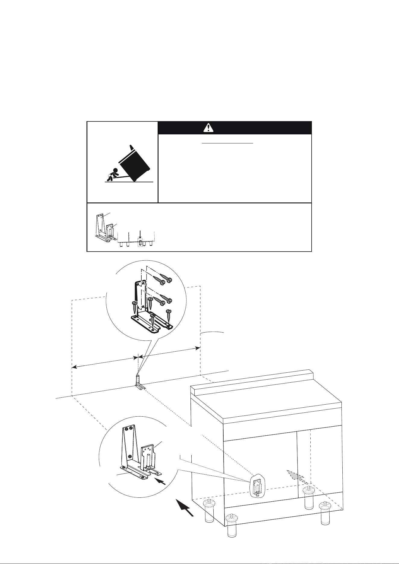
3. Fix the stability bracket in place (g. 1.11). It can be xed as follows:
• To the oor OR on the rear wall by #4 screws (supplied, see NOTE 1 below).
• To the oor AND on the rear wall by #8 screws (supplied, see NOTE 1 below).
• If using the plastic sleeve anchors: drill 5/16” (8mm) diameter holes and insert the supplied plastic sleeve anchors before
attaching the stability bracket with the screws.
NOTE 1: There are 8 x wood screws and 8 x screws with plastic sleeve anchors supplied with the range in two separate kits. Use
the proper screws according to the type of material on the oor and/or wall.
4. Slide the range into place, ensuring the bolt on the adjustable bracket slots under the stability bracket.
• Adjust the length of the bolt as necessary. Ensure the two nuts are well tightened after any adjustments.
IMPORTANT!
• Use the proper screws to x the stability bracket in place according to the type of material on the oor and/or wall.
• Before drilling any holes or inserting any screws into the oor or wall check that you will not damage any wiring or pipes.
WARNING
- Slide range back so bolt head, on the adjustable bracket assembly, is
--under anti-tip bracket.
- Look for the anti-tip bracket securely attached to oor or wall.
- See installation instructions for details.
- Look for the adjustable bracket assembly securely attached to
--the back of the range.
- Slide range forward.
To verify the anti-tip bracket is installed and engaged:
Tip-Over Hazard
Anti-tip bracket
Adjustable bracket
assembly to be xed to
the back of the range
A child or adult can tip the range and be killed.
Install anti-tip device to range and/or structure per installation
instructions.
Engage the range to the anti-tip device Installed to the structure.
Re-engage anti-tip device if range is moved.
Failure to follow these instructions can result in death or serious
burns to children and adults.
Fig. 1.11
=
=
Anti-tip stability
device xing
Adjustable
bracket with
threaded nut
correctly tted
Anti-tip stability
device
Dotted line showing the position
of the range when installed
1212
For installations within the United States, it is highly
recommended to use a 4-wire power cord. Using the
3-wire installation may result in insucient power to
your range, and will result in poor heating performance
resulting in very long cooking times.
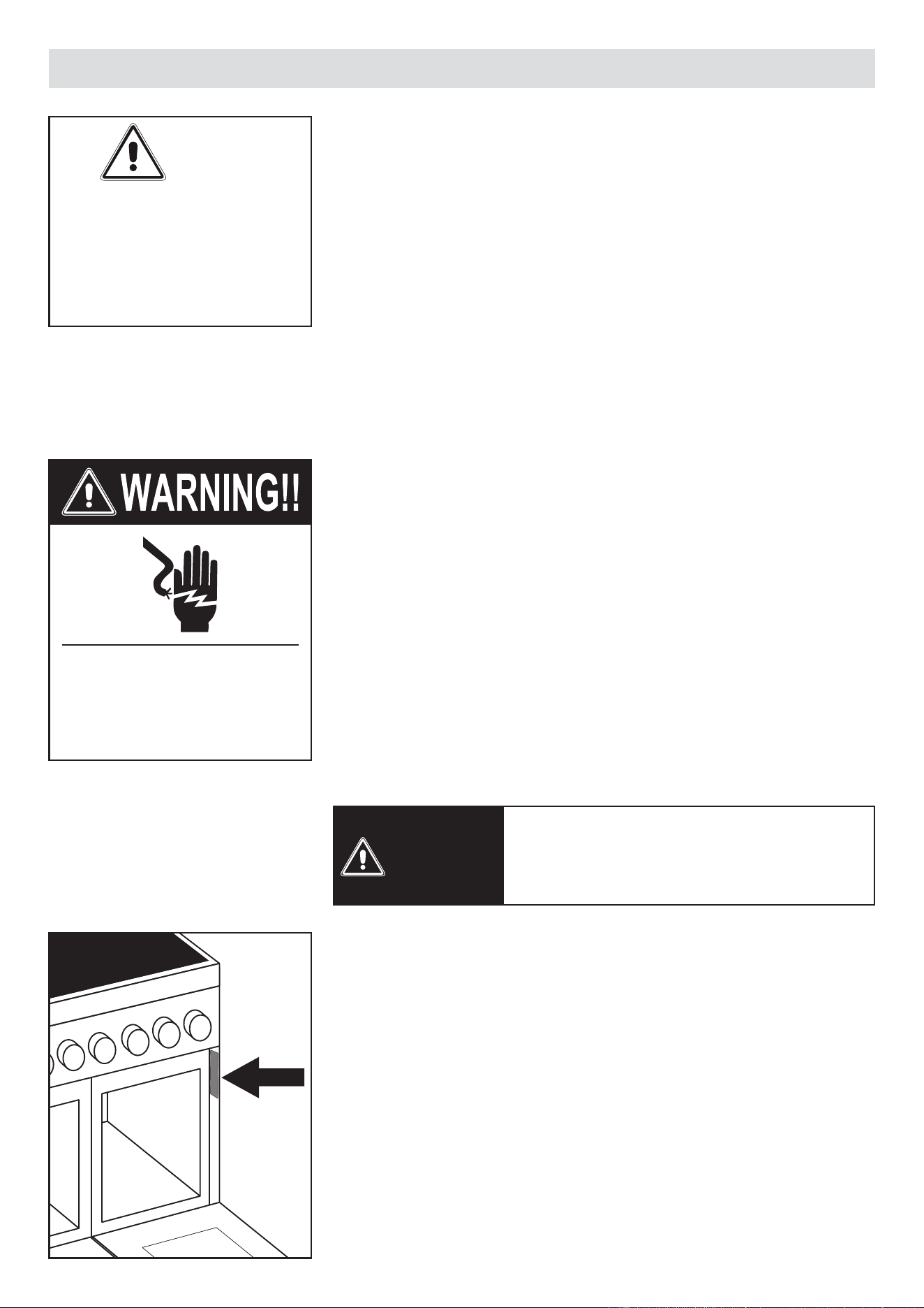
WARNING!!
2. ELECTRICAL CONNECTION
WARNING
TO AVOID ELECTRICAL SHOCK
HAZARD, BEFORE INSTALLING
THE APPLIANCE, SWITCH POWER
OFF AT THE SERVICE PANEL AND
LOCK THE PANEL TO PREVENT
THE POWER FROM BEING
SWITCHED ON ACCIDENTALLY.
Electrical Shock Hazard
Electrically ground range. Failure to
follow these instructions can result
in death, re, or electrical shock.
ELECTRICAL REQUIREMENTS
• This appliance must be properly installed and grounded by a qualified technician in
accordance with the National Electrical Code ANSI/NFPA No.70 (latest edition) and
local electrical code requirements.
IN CANADA: Electrical installation must be in accordance with the current CSA C22.1
Canadian Electrical Codes Part1 and/or local codes.
• This appliance may be connected by means of permanent “Hard Wiring” or “Power
Supply Cord Kit”.
- For USA only: power supply cord is not supplied, but it is available through your local
electric supply house (use power supply cord kits that specify use with a nominal
1” 3/8 (35 mm) diameter connection opening).
- For Canada only: it is mandatory to connect the range by using cordset with plug
supplied.
• Use only 3-conductor or 4-conductor CSA/UL listed range cord provided with proper
terminals. These cords should be provided with strain relief or conduit connector.
Warning: Frame grounded through neutral lead. If used in,
- New branch-circuit installations (1996 NEC),
- Mobile homes,
- Recreational vehicles, or
- In an area where local codes prohibit grounding through neutral, use a 4 conductor
cord or conduit.
• The range must be connected to the proper electrical voltage and frequency as
specified on the rating plate.
• The range can be connected directly to the fused disconnect (or circuit breaker box)
through flexible, armoured or non-metallic sheathed, copper cable (with grounding
wire). Allow two to three feet of slack in the line so that it can be moved if servicing is
ever necessary.
Voltage and Power Consumption
AC 120/240 V 60 Hz 12216 W MAX 51.97 A MAX NEC CALCULATED LOAD 50 A*
AC 120/208 V 60 Hz 9176 W MAX 45.26 A MAX)
* The NEC calculated load is less than the total connected load listed on the rating label.
Location of
nameplate
1313
1 2 3
Terminal Block
Smaller opening
Strain relief bracket
L1
N
L2
PE
L1 N L2
PE
Fig. 2.2
Fig. 2.4
Fig. 2.3
1 2 3
Terminal block
access cover
Fig. 2.1
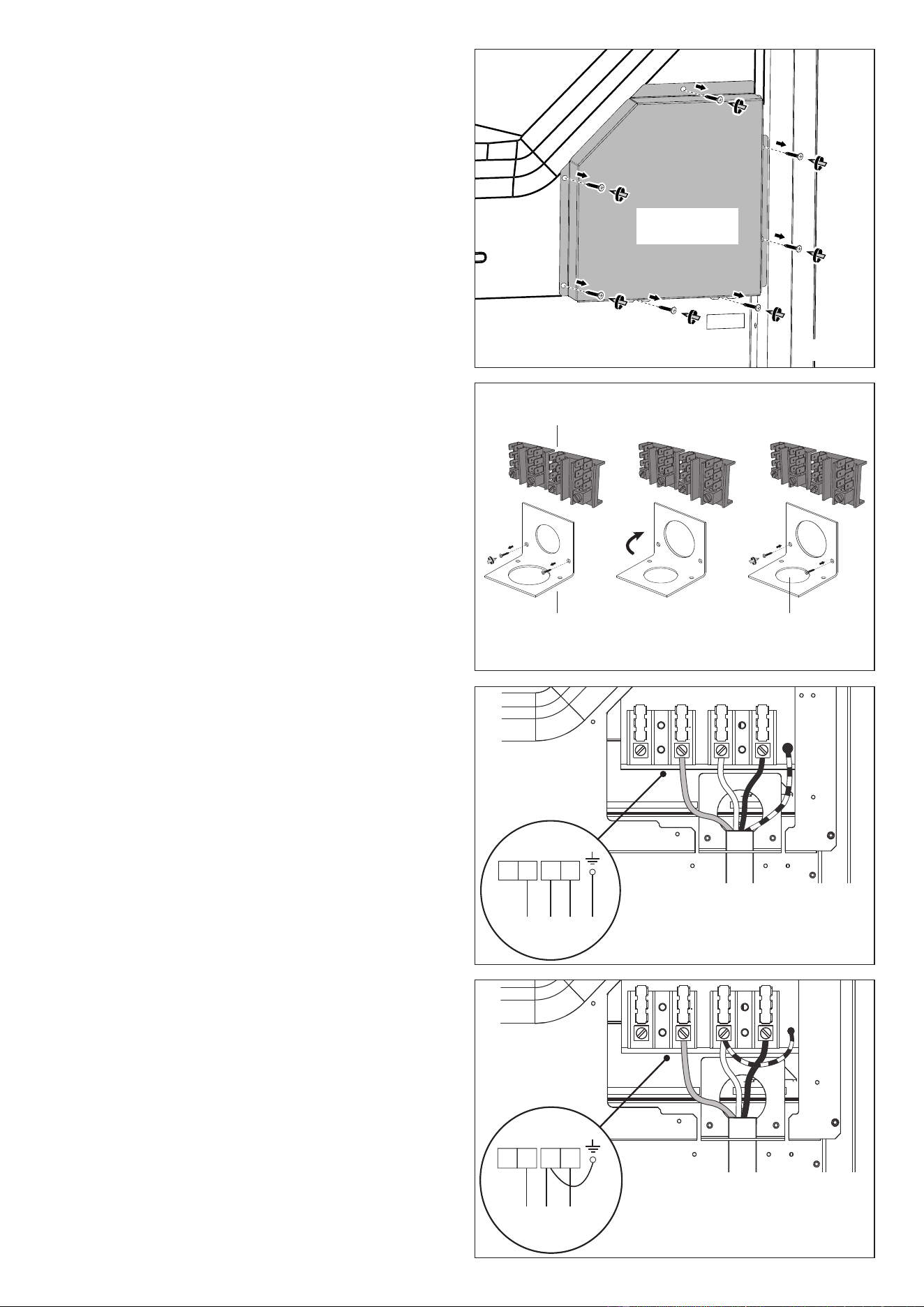
PERMANENT CONNECTION (HARD WIRING)
US only, for Canada it is mandatory to connect the range by
using cordset with plug supplied.
• Units may be hard wired to the power supply. The installer
must provide approved exible aluminum conduit, 3/4”
(19 mm) trade size, maximum 6ft (1.8 m) long. Locate the
terminal block on the rear of the unit and remove access
cover (fig. 2.1).
• The strain relief bracket orientation must be so that the 1” 1/8
(28.6 mm) smaller opening is facing down (fig. 2.2). If not, the
strain relief bracket orientation must be switched in order to
accommodate for a permanent wiring connection:
1. If fitted, remove the factory supplied power cord with
plug.
2. Remove the 2 screws on the bracket.
3. Re-secure bracket with the 2 screws so that the 1” 1/8
(28.6 mm) smaller opening is facing down.
• The conduit must be installed to the terminal block using
an approved conduit connector. The free end of the conduit
must be connected to a junction box provided in the electrical
supply zone.
• Mount a strain relief (not provided) into the 1” 1/8 (28.6
mm) diameter hole located below the terminal block.
Wiring for the unit is to be brought into the terminal block
through the conduit and through the strain relief. Make
suitable connections to the terminal block provided.
• Installer — Show the owner the location of the circuit breaker.
Mark it for easy reference.
4-Wire Installation (fig. 2.3)
1. Loosen the L1, L2 and neutral screws.
2. Mount the conduit fitting to the 1” 1/8 (28.6 mm) hole in the
strain relief bracket.
3. Secure the neutral power lead to the center terminal and
tighten the screw.
4. Secure the L1 and the L2 power leads to the terminals
immediately to the left (L1) and right (L2) of the neutral
terminal. Tighten the screws.
5. Secure the Ground lead to the green screw located to the
right of the terminal block using the supplied cupped washer.
The end of the grounding conductor must be retained by the
cupped washer.
6. Check all connections are securely tightened.
7. Reinstall the Terminal Block cover (fig. 2.1).
3-Wire Connection (using supplied Ground
lead)
(fig. 2.4)
1. Loosen the L1, L2 and neutral screws.
2. Mount the conduit fitting to the 1” 1/8 (28.6 mm) hole in the
strain relief bracket.
3. Secure the supplied Ground lead to the grounding screw to
the right of the terminal block.
4. Secure the Neutral power lead together with the free end of
the Ground lead to the center terminal. Tighten the screw.
5. Secure the L1 and the L2 power leads to the terminals
immediately to the left (L1) and right (L2) of the neutral
terminal. Tighten the screws.
6. Check all connections are securely tightened.
7. Reinstall the Terminal Block cover (fig. 2.1).
1414
Before any operation of maintenance
disconnect the appliance from the
electrical main supply.
RANGES SUPPLIED WITH POWER CORD (WITH PLUG)
ALREADY FITTED
If codes permit and a separate ground wire is used, it is recommended that a
qualied electrician installer determine that the ground path and wire gauge are in
accordance with local codes.
Be sure that the electrical connection and wire size are adequate and in conformance
with:
• ANSI/NFPA 70 latest edition and local codes and ordinances;
• CSA Standard C22.1, Canadian Electrical Code, Part 1 - latest edition, and all local
codes and ordinances.
ONLY FOR CANADA:
A copy of the above code standards can be obtained from:
CANADIAN STANDARDS ASSOCIATION
178 Rexdale Boulevard
TORONTO, ON M9W 1R3
CANADA
• Do not ground to a gas pipe.
• Check with a qualied electrical installer if you are not sure the range is properly
grounded.
• Do not have a fuse in the neutral or ground circuit.
• When a 4-wire, two phase 240-208/120-volt, 60Hz, AC-only electrical supply is
available, a 50 A maximum circuit protection is required, fused on both sides of the
line.
• A time-delay fuse or circuit breaker is recommended.
• This range is equipped with a Certied Power Cord intended to be plugged into
a standard 14-50R wall receptacle. Be sure the wall receptacle is within reach of
range’s nal location.
• Do not use an extension cord.
• In the case of substitution of the power cord always replace it with a suitable CSA or
UL approved one (with the same technical features of the replaced cord).
• Tighten the power cord by using only the power cord strain relief bracket supplied
with the appliance.
• Allow enough slack to easily attach the cord terminals to the terminal block.
• These operations must be carried out only by an authorized technician.
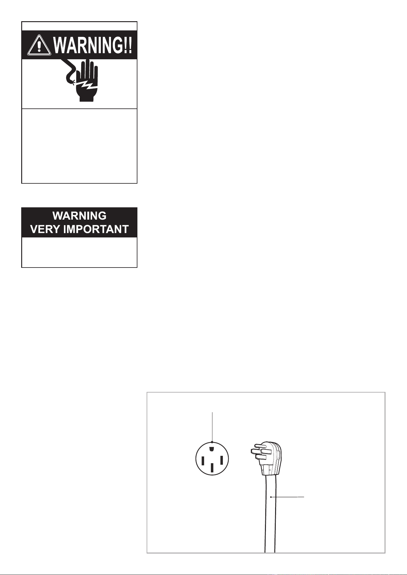
Electrical Shock Hazard
Plug into a grounded outlet.
Do not remove ground prong.
Do not use an adapter.
Failure to follow these instructions
can result in death, re, or electrical
shock.
Power supply cord with
NEMA 14-50P plug
Standard NEMA 14-50R wall receptable
Fig. 2.5
IMPORTANT!
The fourth (ground) prong
should not, under ANY
circumstances, be cut or
removed.
1515
1
6
P1
P6
4P4
3
8
P3
P8
2
7
P2
P7
5P5
1A1
N
J7J8
2A 2
1
6
P1
P6
4P4
3
8
P3
P8
2
7
P2
P7
5P5
SP
H
S
2
4
H
S
2
4
H
S
2
4
H
S
2
4
S1S2
4
Pilot
P1
P2
2
S1S2
4
4a
P1
P2
2
ST2
TM2
TM1
L1
CR
P1
FP1 FP2 FP3 FP4 FP5
P2
P3
P4
P5
TL1
TS1
TLS1
CI1
G1
C1
V1
S1
M
E
L2 N L1
TL2
TLP
CF
F1
PR1
F2
L2
CI2
G2
C2
V2
S2
TS2
S1S2
4
Pilot
P1
P2
2
S1S2
4
Pilot
P1
P2
2
S1S2
4
Pilot
P1
P2
2
4A
HS
2
4
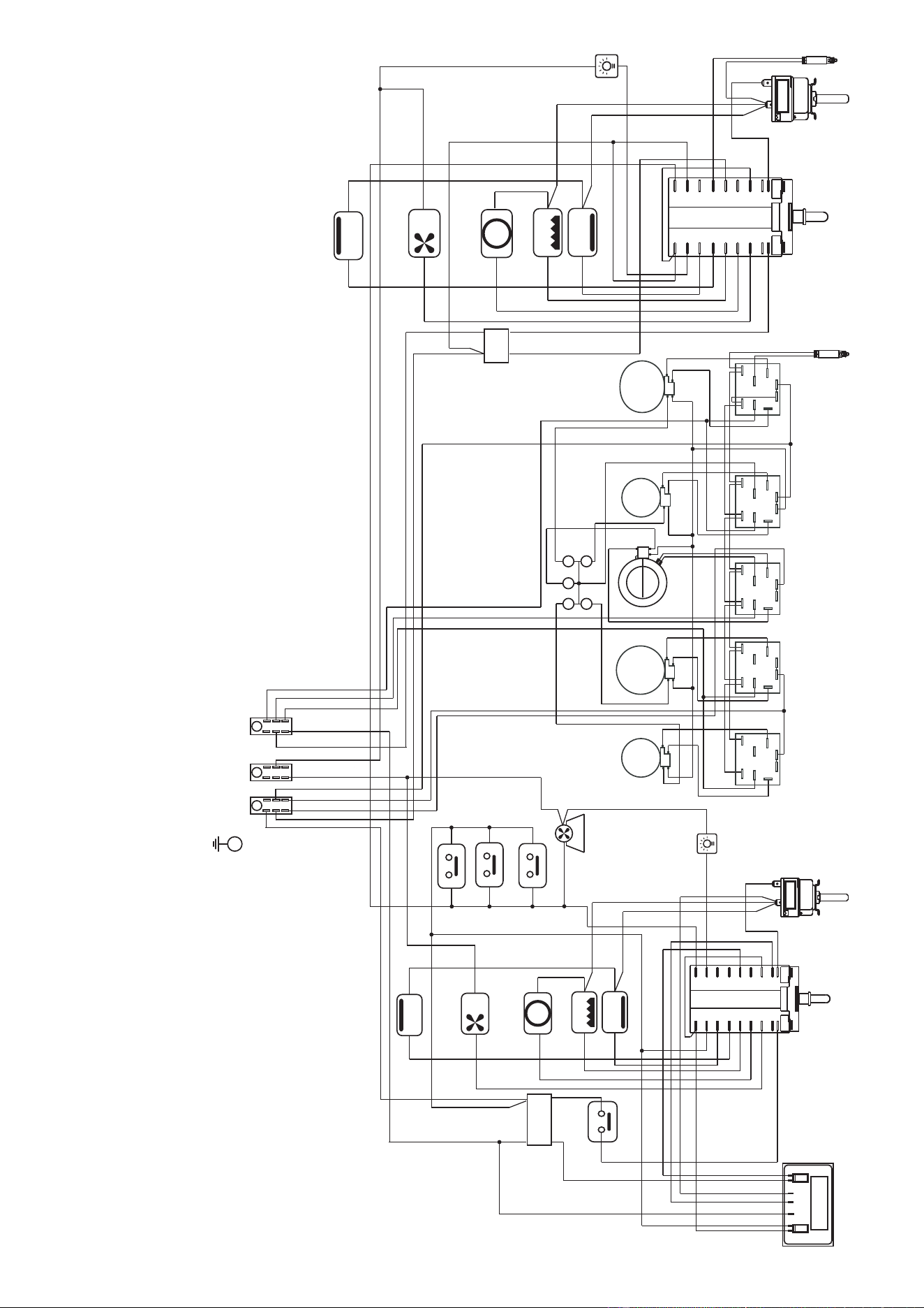
LEFT OVEN (FOUR GAUCHE)RIGHT OVEN (FOUR DROITE)
RIGHT OVEN (FOUR DROITE)
TS2 Safety thermal overload (Thermolimitateur de sécurité)
TL2 Thermal overload (Thermolimitateur de sécurité)
L2 Oven lamp (Lampe du four)
ST2 Thermostat pilot lamp (Voyant de thermostat)
F2 Oven switch (Commutateur four)
TM2 Oven thermostat (Thermostat four)
S2 Oven bottom heating element (Élément chauant inférieur)
CI2 Oven top heating element (Élément chauant supérieur)
G2 Oven broil heating element (Élément chauant de gril)
C2 Oven circular heating element (Élément chauant circulaire)
V2 Oven fan motor (Moteur du ventilateur du four)
LEFT OVEN (FOUR GAUCHE)
TS1 Safety thermal overload (Thermolimitateur de sécurité)
TLS1 Safety thermal overload, 95°C (Thermolimitateur de sécurité, 95°C)
TL1 Thermal overload (Thermolimitateur de sécurité)
L1 Oven lamp (Lampe du four)
PR1 Electronic programmer (Programmateur électronique)
F1 Oven switch (Commutateur four)
TM1 Oven thermostat (Thermostat four)
S1 Oven bottom heating element (Élément chauant inférieur)
CI1 Oven top heating element (Élément chauant supérieur)
G1 Oven broil heating element (Élément chauant de gril)
C1 Oven circular heating element (Élément chauant circulaire)
V1 Oven fan motor (Moteur du ventilateur du four)
ELECTRIC DIAGRAM KEY (LÉGENDE DU SCHÉMA ÉLECTRIQUE)
M Terminal block (Bloc de raccordement)
E Earth connection (Connexion de mise à la terre)
CF Cooling fan motor (Moteur de ventilateur de refroidissement)
HOB (TABLE DE CUISSON)
P1/2/4/5 Cooking zones (Zones de cuisson)
P3 Double cooking zone (Zone de cuisson double)
FP1/2/4/5 Energy regulators (Régulateur d'énergie)
FP3 Energy regulator, double zone (Régulateur d'énergie, zone double)
CR Residual heat indicators (Indicateurs de chaleur résiduelle)
SP Power on indicator lamp (Voyant de mise sous tension)
TLP Thermal overload, 55°C (Thermolimitateur de sécurité, 55°C)

The manufacturer cannot be held responsible for possible inaccuracies due to
printing or transcription errors in the present booklet.
The manufacturer reserves the right to make all modications to its products deemed
necessary for manufacture or commercial reasons at any moment and without prior
notice, without jeopardising the essential functional and safety characteristics of the
appliances.
Cod 1106888 - ß1