Page | 1
E2306-20
Rev. 0 11/16/24
INSTALLATION OPERATION INSTRUCTIONS
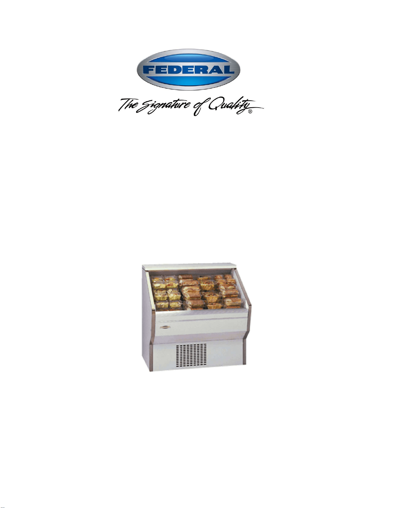
Self-Contained
Including Hybrid
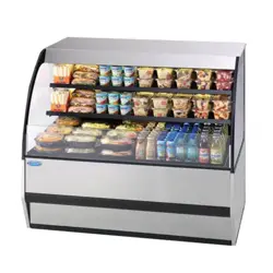
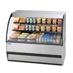
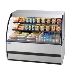
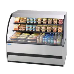
RSS3-2B & -3B
RSS4-2B & -3B
KEEP THIS MANUAL FOR FUTURE REFERENCE
Engineering and technical data are subject to change without notice.
FEDERAL INDUSTRIES 215 Federal Avenue Belleville, WI 53508
Toll Free 1(800)356-4206 WI Phone (608)424-3331 Fax: (608)424-3234

Page | 2
Contents
COVER………………………………………………………………………..….…...... 1
CONTENTS……………………………………………………………………………...2
INTRODUCTION………………………………………………………………………..3
WARNING LABELS & SAFETY INSTRUCTIONS…………………………………4
REFRIGERATION WARNING INSTALL-REPAIR-DECOMMISSIONING…...5-10
PRE-INSTALLATION PROCEDURES……………………………………………..11
INSPECTION FOR SHIPPING DAMAGE…………………………………………...…11
INSTALLATION INSTRUCTIONS…………………………………………………..11
LOCATING THE DISPLAY CASE……………………………………………………………………11
LEVELING THE CASE……………………………………………………………………………..….12
GRILL REMOVAL………………………………………………………………………………………12
CONDENSATE EVAPORATOR……………………………………………………………..……….12
ELECTRICAL INFORMATION & GROUNDING ……………………………….…13
OPERATING INSTRUCTIONS………………………………………………….…...14
CONTROLS……………………………………………………………………………………………..14
TEMPERATURE CONTROL………………………………………………………………………14-17
INITIAL STARTUP………………………………………………………………………………….…..18
PLACING PRODUCT IN CASE……………………………………………………………………….18
PERIODIC MAINTENANCE…………………………………………………………………...………19
SERVICE INFORMATION……………………………………………………………20
PRE-SERVICE CHECKLIST………………………………………………………………………..…21
SPECIAL SERVICE SITUATIONS……………………………………………………………………22
SALE & DISPOSAL………………………………………………………………..….23
OWNER RESPONSIBILITY…………………………………………………………………………...23
REFRIGERATION & ELECTRICAL DATA- RSS3 & 4 SC-2B & -3B……….….24
REPLACEMENT PARTS- RSS3 & RSS4 -2B & -3B……………………………..25
WIRING DIAGRAM SELF-CONTAINED (RSS3, 4 –SC-2B & 3B)..…………….26
Information contained in this manual covers models:
RSS3SC-2B RSS4SC-2B
RSS3SC-3B RSS4SC-3B
Including Hybrid Models
Page | 3
INTRODUCTION
Thank you for purchasing a Federal Industries display case. This manual contains
important instructions for installing and servicing the RSS, Refrigerated Self-Service
Merchandisers. A repair parts list and wiring diagram are also included in the manual.
Read all of these documents carefully before installing or servicing your case.
Serial Number
Record the model and serial numbers of the case for easy reference. Always refer to both `
model and serial numbers in your correspondence regarding the case.
Case Model_________________ Serial Number_______________
Condensing Unit Model________ Serial Number_______________
This manual cannot cover every installation, use or service situation. If you need additional
information, call or write us:
NOTICE
Read this manual before installing your case. Keep this manual and refer to it
before doing any service on the equipment. Failure to do so could result in
personal injury or damage to the case.
NOTICE
Installation and service of the electrical components in the case must be performed
by a licensed electrician.
The portions of this manual covering electrical components contain technical instructions
intended only for persons qualified to perform electrical work.
DANGER
Improper or faulty hookup of electrical components in the case can result in severe
injury or death.
All electrical wiring hookups must be done in accordance with all applicable local,
regional, or national standards.
Warranty/Technical Service Department
Federal Industries
Toll Free (800)356-4206
WI Phone (608)424-3331
service
@federalind.com
Page | 4
WARNING LABELS & SAFETY
INSTRUCTIONS
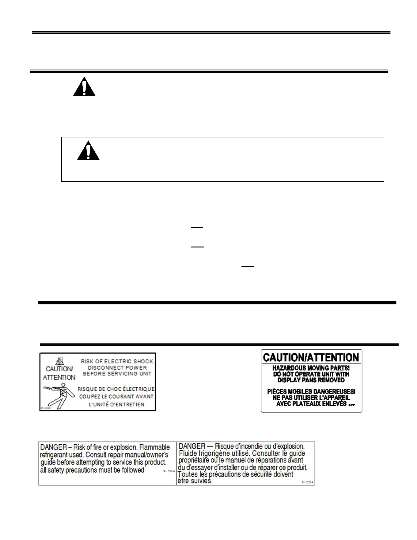
This is the safety-alert symbol. When you see this symbol on your case or
in the manual, be alert to the potential for personal injury or damage to
your equipment.
Be sure you understand all safety messages and always follow recommended
precautions and safe operating practices.
Important safety information is presented in this section and throughout the manual.
The following signal words are used in the warnings and safety messages:
DANGER: Severe injury or death will occur if you ignore the message.
WARNING: Severe injury or death can occur if you ignore the message.
CAUTION: Minor injury or damage to your case can occur if you ignore the message.
NOTICE: This is important installation, operation, or service information. If you
ignore the message, you may damage your case.
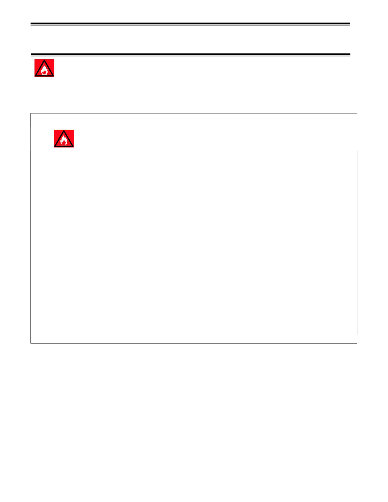
The warning and safety labels shown throughout this manual are placed on your Federal
Industries case at the factory. Follow all warning label instructions. If any warning or
safety labels become lost or damaged, call our customer service department at
1(800)356-4206 for replacements.
This label is located on the back of the case and This label is located below the
on the front of the case behind the access panel. display pan.
This label is located by condensing unit
Notice to Employers
You must make sure that everyone who installs, uses, or services your case is
thoroughly familiar with all safety information and procedures.
Page | 5
REFRIGERATION WARNING
INSTALLATION-REPAIR-DECOMMISSIONING
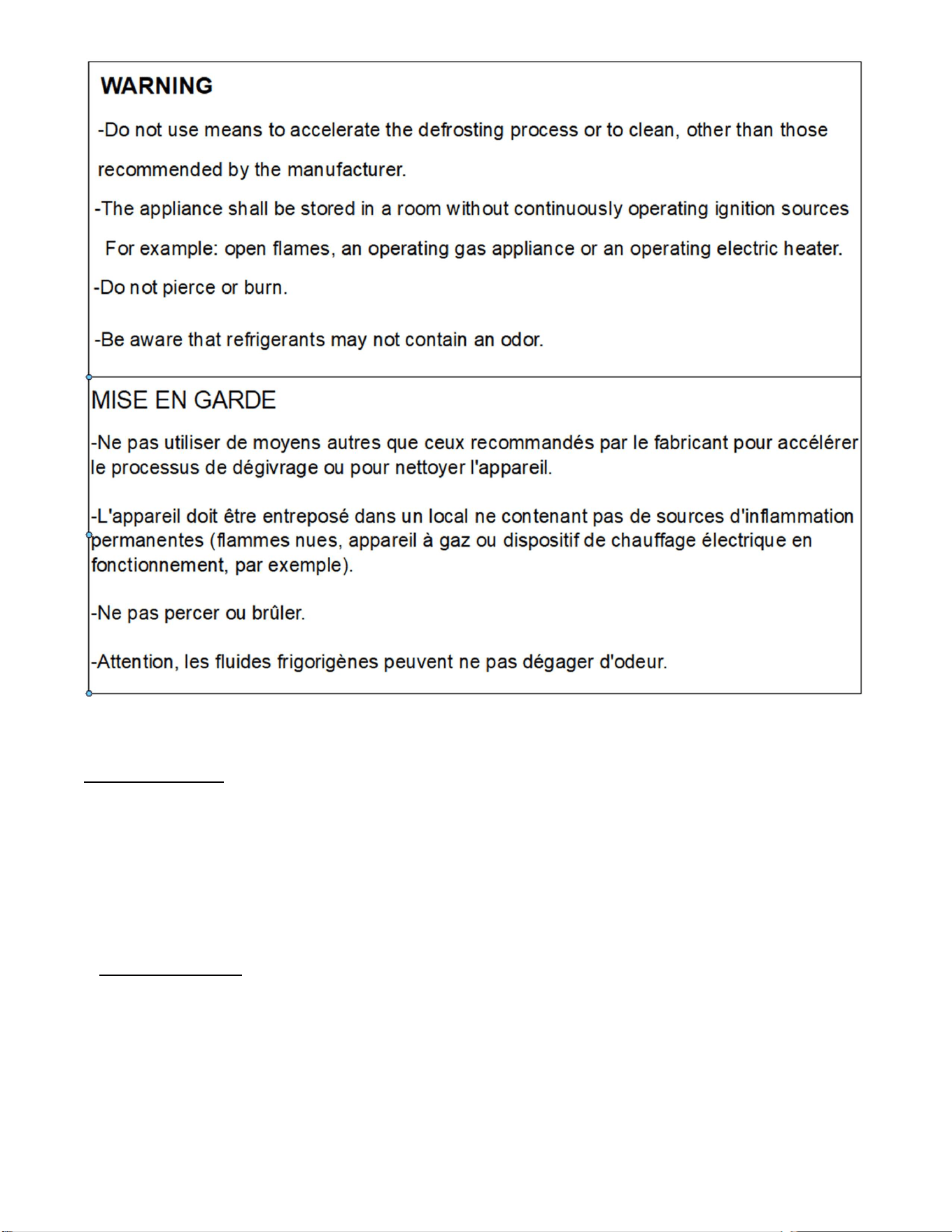
This is the Danger-Flammable symbol. When you see this symbol on your case or in the
manual, be alert to the potential for risk of fire or explosion.
Be sure you understand all safety messages and always follow recommended precautions and safe
operating procedures.
DANGER
Risk of fire or explosion. Flammable refrigerant used. To be repaired only by trained service
personnel. Do not puncture refrigerant tubing. Dispose of properly in accordance with federal or
local regulations
Consult repair manual/owner’s guide before attempting to service this product. All safety
precautions must be followed.
Follow handling instructions carefully in compliance with national regulations.
Auxiliary devices which may be ignition sources shall not be installed in the ductwork, other
than auxiliary devices listed for use with the specific appliance.
Do not store explosive substances (such as aerosol cans with a flammable propellant) in this
case.
Do not use an electrical appliance INSIDE the food storage compartments unless its type is
recommended by manufacturer.
Flammable refrigerant type specified on case nameplate is on the serial label.
APPLIES TO R290 REFRIGERANT MODELS ONLY! Contains a charge of R290 refrigerant with a
lower flammability limit (LFL) of .038kg/m³. See table for amount of charge.
Page | 6
3. Qualification: All refrigeration and electrical maintenance, service, and repair must be
performed by a Certified Technician that is trained in the required flammable refrigerants safety
procedures. Technicians must read the entire section “REFRIGERATION WARNINGS
SECTION” of this manual.
Including but not limited to the following:
a) breaking into the refrigerating circuit.
b) opening of sealed components.
c) opening of ventilated enclosures.
4.Checks to Area: Prior to beginning work on systems containing FLAMMABLE
REFRIGERANTS, safety checks are necessary to ensure that the risk of ignition is minimized
prior to conducting work on the system.
-Capacitors are discharged: this shall be done in a safe manner to avoid possibility of
sparkling.
- No live electrical components and wiring are exposed while charging, recovering or purging
the system.
- Continuity of earth bonding.

Page | 7
-Work shall be undertaken under a controlled procedure to minimize the risk of a
flammable gas or vapor being present while the work is being performed.
-All maintenance staff and others working in the local area shall be instructed on the nature of
the work being carried out. Work in confined spaces shall be avoided.
-The area shall be checked with an appropriate refrigerant detector prior to and during
work, to ensure the technician is aware of potentially toxic or flammable atmospheres.
Ensure that the leak detection equipment being used is suitable for use with all applicable
refrigerants, i.e., non-sparking, adequately sealed, or intrinsically safe.
-If any hot work is to be conducted on the refrigerating equipment or any associated parts,
appropriate fire extinguishing equipment shall be available on hand. A dry chemical or CO2 fire
extinguisher should be adjacent to the charging area.
-No person carrying out work in relation to a REFRIGERATING SYSTEM which involves
exposing any pipe work shall use any sources of ignition in such a manner that it may lead to
the risk of fire or explosion. All possible ignition sources, including cigarette smoking, should
be kept sufficiently far away from the site of installation, repairing, removing and disposal,
during which refrigerant can possibly be released to the surrounding space. Prior to work
taking place, the area around the equipment shall be surveyed to make sure that there are no
flammable hazards or ignition risks. “No Smoking” signs shall be displayed.
-Ensure that the area is in the open or that it is adequately ventilated before breaking into the
system or conducting any hot work. A degree of ventilation shall continue during the period
that the work is carried out. The ventilation should safely disperse any released refrigerant and
preferably expel it externally into the atmosphere.
-Where electrical components are being changed, they shall be fit for the purpose and to the
correct specification so as to minimize the risk of possible ignition due to incorrect parts. At all
times, the manufacturer’s maintenance and service guidelines shall be followed. If in doubt,
consult the manufacturer’s technical department for assistance. The following checks shall be
applied to installations using flammable refrigerants:
a) the actual REFRIGERANT CHARGE is in accordance with the room size within which the
refrigerant containing parts are installed.
b) The ventilation machinery and outlets are operating adequately and are not obstructed.
c) Markings of the equipment continue to be visible and legible. Markings and signs
that are illegible shall be corrected.
d) Refrigerating pipes or components are installed in a position where they are
unlikely to be exposed to any substance which may corrode refrigerant containing
-Repair and maintenance to electrical components shall include initial safety checks and
component inspection procedures. If a fault exists that could compromise safety, then no
electrical supply shall be connected to the circuit until it is satisfactorily dealt with. If the fault
cannot be corrected immediately but it is necessary to continue operation, an
An adequate temporary solution should be used. This shall be reported to the owner of the
Initial safety checks shall include:

Page | 8
5. Repairs to sealed components
-During repairs to sealed components, all electrical supplies shall be
disconnected from the equipment being worked upon prior to any removal of sealed
covers, etc. If it is necessary to have an electrical supply to equipment during
servicing, then a permanently operating form of leak detection shall be located at the most
critical point to warn of a potentially hazardous situation.
-Particular attention shall be paid to the following to ensure that by working on
electrical components, the casing is not altered in such a way that the level of protection is
affected. This shall include damage to cables, excessive number of connections, terminals not
made to original specification, damage to seals, incorrect fitting of glands, etc. Ensure that the
apparatus is mounted securely.
Ensure that seals or sealing materials have not degraded to the point that they no longer serve
the purpose of preventing the egress of flammable atmospheres. Replacement parts shall be
in accordance with the manufacturer’s specifications.
-Do not apply any permanent inductive or capacitance loads to the circuit without ensuring that
this will not exceed the permissible voltage and current permitted for the equipment in use.
NOTE The use of silicon sealants can inhibit the effectiveness of some types of leak detection
equipment. Intrinsically safe components do not have to be isolated prior to working on them.
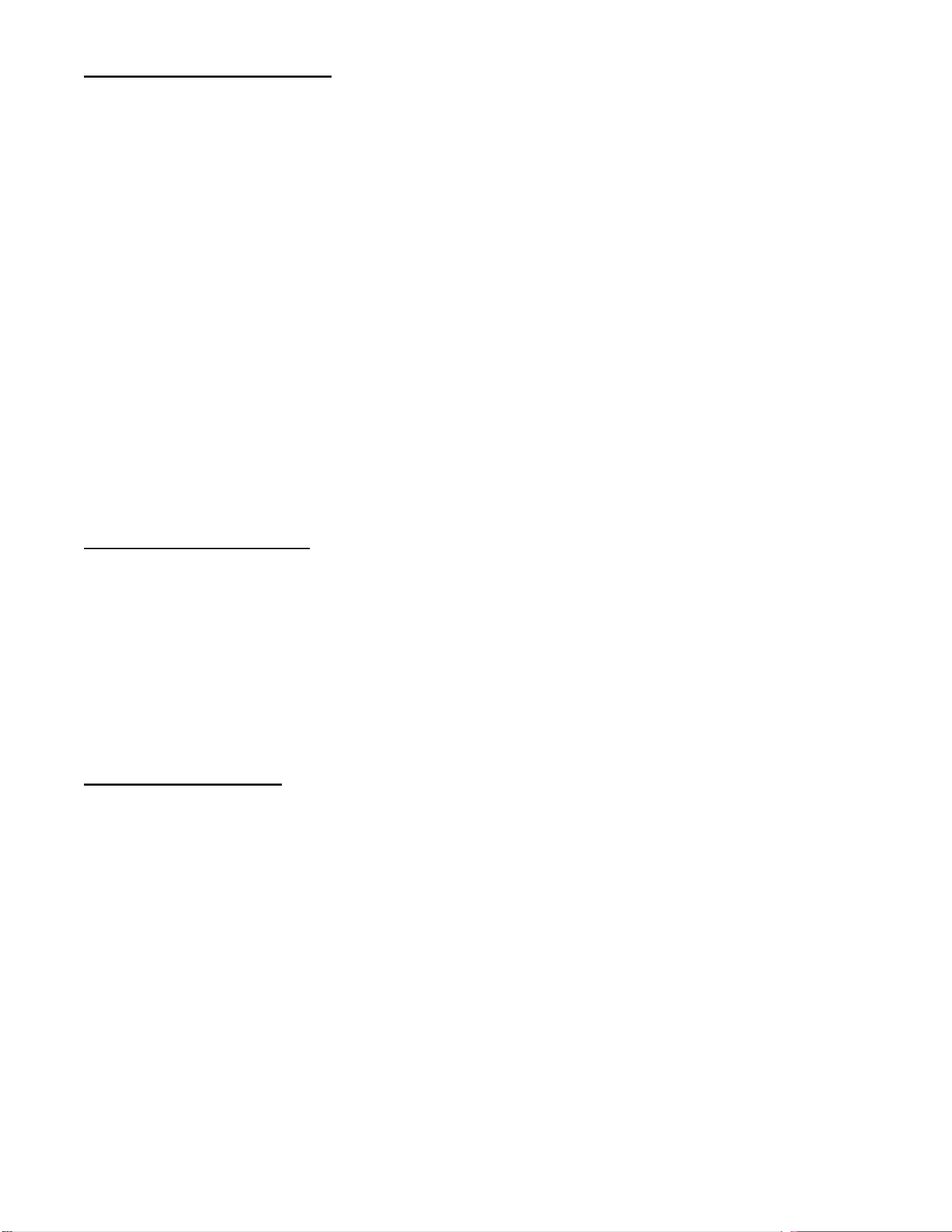
8. Detection of flammable refrigerants: Under no circumstances shall potential ignition
sources be used in the searching for or detection of refrigerant leaks. A halide torch (or any
other detector using a naked flame) shall not be used.
The following leak detection methods are deemed acceptable for all refrigerant
systems:
-Electronic leak detectors may be used to detect refrigerant leaks but, in the case of
FLAMMABLE REFRIGERANTS, the sensitivity might not be adequate or might need
recalibration. (Detection equipment shall be calibrated in a refrigerant-free area.) Ensure that
the detector is not a potential source of ignition and is suitable for the refrigerant used. Leak
detection equipment shall be set at a percentage of the LFL of the refrigerant and shall be
calibrated to the refrigerant employed, and the appropriate percentage of gas (25 % maximum)
is confirmed.
-Leak detection fluids are also suitable for use with most refrigerants but the use of
detergents containing chlorine shall be avoided as the chlorine can react with the
refrigerant and corrode the copper pipework.
NOTE Examples of leak detection fluids are
– bubble method,
– fluorescent method agents.
If a leak is suspected, all naked flames shall be removed/extinguished.
If a leakage of refrigerant is found which requires brazing, all the refrigerants shall be
recovered from the system, or isolated (by means of shut off valves) in a part of the system
remote from the leak.
Page | 9
9. Removal and Evacuation: When breaking into the refrigerant circuit to make repairs-or for
any other purpose-conventional procedures shall be used. However, for flammable refrigerants
it is important that the best practice be followed, since flammability is a consideration. The
following procedure shall be adhered to:
a. Safely remove refrigerant following local and national regulations.
b. Purge the circuit with inert gas.
c. Evacuate (optional for A2L).
d. Purge with inert gas (optional for A2L).
e. Open the circuit by cutting or brazing.
The refrigerant change shall be recovered into the correct recovery cylinders if venting is not
allowed by local and national codes. For appliances containing flammable refrigerants, the
system shall be purged with oxygen-free nitrogen to render the appliance safe for flammable
refrigerants. This process might need to be repeated several times. Compressed air or oxygen
shall not be used for purging refrigerant systems. For appliances containing flammable
refrigerants, refrigerant purging shall be achieved by breaking the vacuum in the system with
oxygen-free nitrogen and continuing to fill until the working pressure is achieved, then venting
to atmosphere, and finally pulling down to a vacuum (optional for A2L). This process shall be
repeated until no refrigerant is within the system (optional for A2L). When the final oxygen-free
nitrogen change is used, the system shall be vented down to atmospheric pressure to enable
work to take place. Ensure that the outlet for the vacuum pump is not close to any potential
ignition sources and that ventilation is available.
10. Charging procedures: In addition to conventional charging procedures, the following
requirements shall be followed.
a. Ensure that contamination of different refrigerants does not occur when using charging
equipment. Hoses or lines shall be as short as possible to minimize the amount of refrigerant
contained in them.
b. Cylinders should be kept in an appropriate position according to the instructions.
c. Ensure that the REFRIGERATING SYSTEM is earthed prior to charging the system with
refrigerant.
d. Label the system when charging is complete (if not already).
e. Extreme care shall be taken not to overfill the REFRIGERATING SYSTEM.
11. Decommissioning: Before carrying out this procedure, it is essential that the technician is
completely familiar with the equipment and all its details. It is recommended good practice that
all refrigerants are recovered safely. Prior to the task being carried out, an oil and refrigerant
sample shall be taken in case analysis is required prior to re-use of recovered refrigerant. It is
essential that electrical power is available before the task commences.
a. Become familiar with the equipment and its operation.
b. Isolate the system electrically.
c. Before attempting the procedure, ensure that:
i. Mechanical handling equipment is available, if required, for handling refrigerant cylinders.
ii. All personal protective equipment is available and is being used correctly.
iii. The recovery process is supervised at all times by a competent person.
iv. Recovery equipment and cylinders conform to the appropriate standards.
d. Pump down the refrigerant system, if possible.
e. If a vacuum is not possible, make a manifold so that refrigerant can be removed from
various parts of the system.
f. Make sure that the cylinder is situated on the scales before recovery takes place.
g. Start the recovery machine and operate in accordance with instructions.

Page | 10
h. Do not overfill cylinders (no more than 80% volume liquid charge).
i. Do not exceed the maximum working pressure of the cylinder, even temporarily.
j. When the cylinders have been filled correctly and the process completed, make sure that the
cylinders and the equipment are removed from the site properly and all isolation valves on the
equipment are closed off.
k. Recovered refrigerant shall not be charged into another refrigerating system unless it has
been cleaned and checked.
12. Labeling: Equipment shall be labeled stating that it has been de-commissioned and
emptied of refrigerant. The label shall be dated and signed. For appliances containing
flammable refrigerants, ensure that there are labels on the equipment stating the equipment
contains flammable refrigerant.
13.Recovery: When removing the refrigerant from a system, either for servicing or
decommissioning, it is recommended good practice that all refrigerants are removed safely.
When transferring refrigerant into cylinders, ensure that only appropriate refrigerant recovery
cylinders are employed. Ensure that the correct number of cylinders for holding the total
system charge is available. All cylinders to be used are designated for the recovered
refrigerant and labeled for that refrigerant (i.e., special cylinders for the recovery of refrigerant).
Cylinders shall be complete with pressure-relief valve and associated shut-off valve in good
working order. Empty recovery cylinders are evacuated and, if possible, cooled before
recovery occurs.
The recovery equipment shall be in good working order with a set of instructions concerning
the equipment that is at hand and shall be suitable for the recovery of all appropriate
refrigerants including, when applicable, FLAMMABLE REFRIGERANTS. In addition, a set of
calibrated weighing scales shall be available and in good working order. Hoses shall be
complete with leak-free disconnect coupling and in good condition. Before using the recovery
machine, check that it is in satisfactory working order, has been properly maintained and that
any associated electrical components are sealed to prevent ignition in the event of refrigerant
release. Consult manufacturer if in doubt.
The recovered refrigerant shall be returned to the refrigerant supplier in the correct recovery
cylinder, and the relevant waste transfer note arranged. Do not mix refrigerants in recovery
units and especially not in cylinders.
If compressors or compressor oils are to be removed, ensure that they have been evacuated
to an acceptable level to make certain that FLAMMABLE REFRIGERANT does not remain
within the lubricant. The evacuation process shall be carried out prior to returning the
compressor to the suppliers. Only electric heating to the compressor body shall be employed
to accelerate this process. When oil is drained from a system, it shall be carried out safely.
Page | 11
PRE-INSTALLATION PROCEDURES
Inspection for Shipping Damage
You are responsible for filing all freight claims with the delivering truck line. Inspect all
cartons and crates for damage as soon as they arrive. If damage is noted to shipping
crates or cartons or if a shortage is found, note this on the bill of lading (all copies) prior
to signing.
If damage is discovered when the case is uncrated, immediately call the delivering truck
line and follow up the call with a written report indicating concealed damage to your
shipment. Ask for an immediate inspection of your concealed damage item. Crating
material must be retained to show the inspector from the truck line.
INSTALLATION INSTRUCTIONS
IMPORTANT: Read this Section of this manual located on page 5.
“REFRIGERATION WARNING & INSTALLATION-REPAIR-DECOMMISSIONING”
All refrigeration and electrical work must be performed by certified technicians.
The installation of the appliance and the refrigerant must only be performed by Federals
approved Service or suitably qualified person.
Appliance to be installed in accordance with safety standards ANSI/ASHREA 15.
The appliance shall not be installed in public corridors or lobbies.
This case is designed for a class 2 environment.
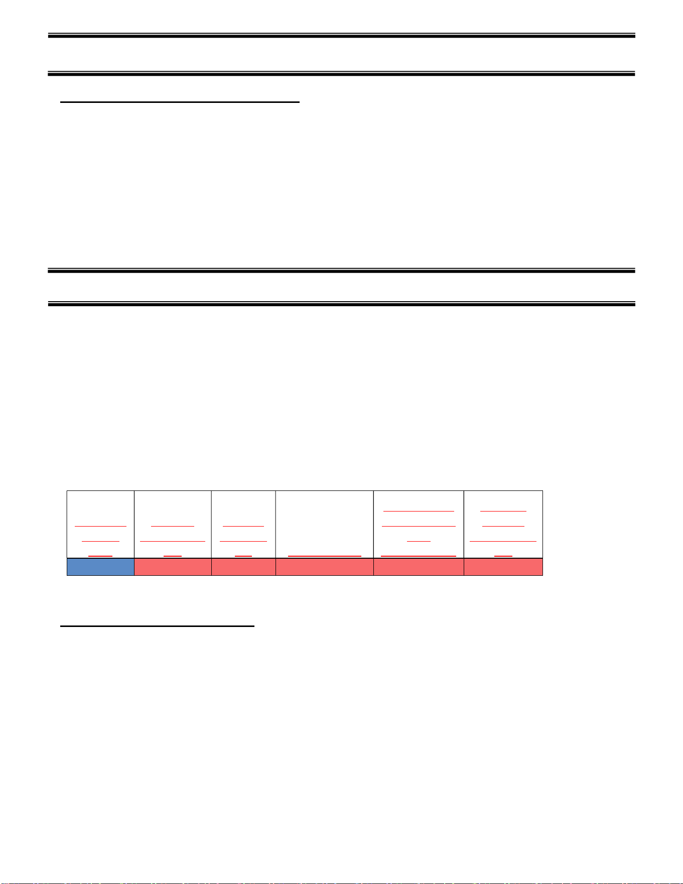
Test room
climate
class
Dry bulb
temperature
[°F]
Relative
Humidity
[%] Dew point [°F]
Water vapour
mass in dry air
[lbm
water/lbm air]
Required
Test Lab
Temperature
[°F]
2.0 71.6 65 59.36 0.0108 89.6
NSF TYPE 1 Temperature cannot exceed 75 deg F and 55% humidity.
Locating the Display Case
The case should be located where it is not subjected to the direct rays of the sun, heating
ducts, grills, radiators, or ceiling fans, nor should it be located near open doors or main
door entrances. Avoid locations where there is excessive air movement or air
disturbances and avoid high humidity locations such as near cases with water misting or
fogging devices.
The case requires a minimum of six (6”) inch clearance at the rear of the unit for air
discharge. Do not locate case with back tight against a wall. No clearance is needed on
the sides of the unit.
Page | 12
Leveling the Case
The case must be level for proper drainage of defrost water to the condensate evaporator
or floor drain. The case can be leveled by placing metal shims under welded steel frame
as required.
To comply with NSFI requirements, the base of the unit should be sealed to the floor with
NSFI listed sealant after installing and leveling unless a minimum of 6” high legs or
casters are provided.
Grill Removal
The front and rear grill require removal for case installation. Both grills are secured with
self-tapping machine screws. To remove front grill remove the two screws, grille lifts up
and tilts out at the bottom. The screws in the front grille are for shipping only; they do
not need to be replaced after removal.
Both grills must be in place for proper operation of the case. Grills must be reinstalled
after initial case installation.
Condensate Evaporator
IMPORTANT: Read this Section of this manual located on page 5.
“REFRIGERATION WARNING &INSTALLATION-REPAIR-DECOMMISSIONING”
All refrigeration and electrical work must be performed by certified technicians.
NOTICE: Steam from the condensate evaporator may be visible around the
base of the merchandiser during normal operation.
Do not use other means to defrost coil other than recommended by manufacturing
This merchandiser may be furnished with an electric condensate evaporator, or an
electric condensate pump. Plumbing connections are not required, unless
merchandiser is specifically ordered without a condensate evaporator or pump.
The condensate evaporator can be removed from the merchandiser, and the
condensate drain can be plumbed to an external drain to conserve energy. To remove
the condensate evaporator, disconnect the wires at the condensate evaporator. This
must be done by a qualified electrician.
This is an open merchandiser and can produce a large amount of condensate water.
To ensure that adequate evaporator capacity is available, a high wattage heater is
used.
Make sure that the condensate drain line has not been dislodged during shipment and
that the drain trap terminates properly over the water reservoir
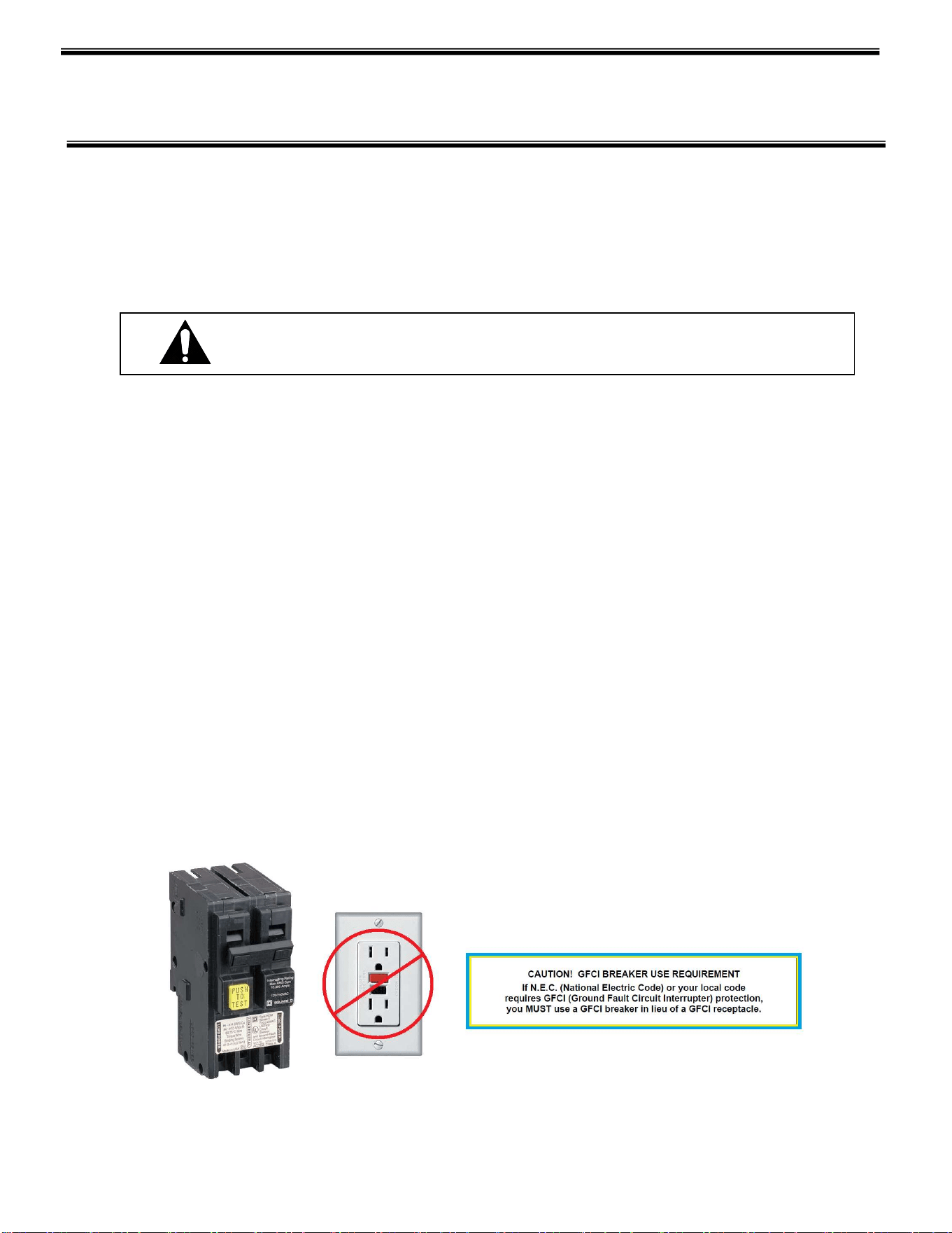
DANGER: Electrical shock hazard. Do not operate unit with panels
removed.
Page | 13
ELECTRICAL INFORMATION &
GROUNDING
IMPORTANT: Read this Section of this manual located on page 5.
“REFRIGERATION WARNING &INSTALLATION-REPAIR-DECOMMISSIONING”
All refrigeration and electrical work must be performed by certified technicians.
This Case Must Be Grounded
All of the case electrical connections must be performed only by a licensed electrician.
All electrical wiring hookups must be done in accordance with all applicable local,
regional, or national standards.
A separate circuit for each case is recommended to avoid the possibility of other
appliances on the same circuit from overloading the circuit and causing malfunction.
The electrical service must be grounded upon installation.
This unit is designed for permanent connection to a power source. See the electrical
data plate at the rear of the unit for proper circuit size and wire ampacity.
On self-contained models two (2) power supplies are required. Connect a separate 120
volt, 60 HZ, 1 phase power supply to the display case junction box and a separate 120
volt, 60 HZ, 1 phase power supply to the condensate evaporator junction box.
Cases with optional cord & plug ( RSS3 & RSS4 ) require ( 1 ) 120v, 60hz, 1 phase 20 amp
power supply, a lower wattage condensate pan or pump is used.
DANGER: Improper or faulty hookup of electrical components in the
display case can result in severe injury or death.
Page | 14
OPERATING INSTRUCTIONS
Controls
Refrigeration System Power Switch
This switch is located in the back of the unit and is accessible through an oval slot. This
switch controls the refrigeration system, the evaporator fans, lights, and anti-sweat
heaters. It does not control the power to the condensate water evaporator.
Light Switch (Optional Case Light)
If the unit is supplied with the optional light, it can be turned on and off by a switch
located at the top light housing.
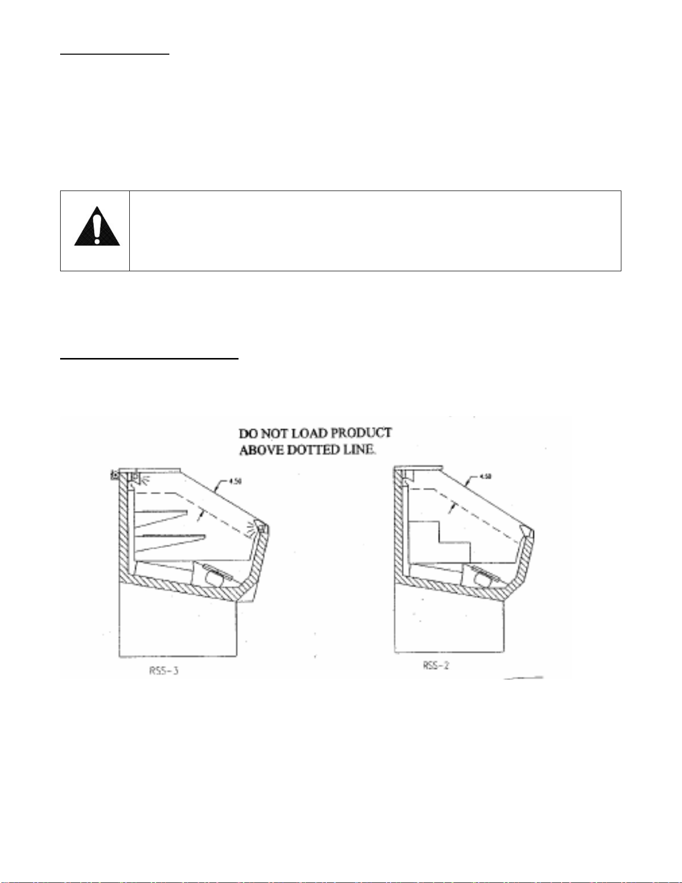
Temperature Control
Located in the left front behind the base grille on front air intake and discharge and
hybrid display case or on the back right on rear air intake and discharge cases, the
temperature control allows the user to adjust the temperature of the display
merchandiser to their needs.
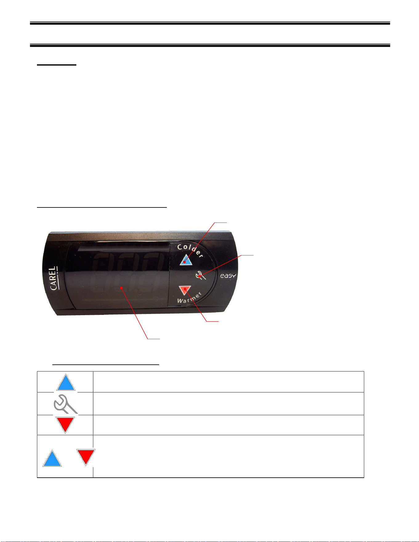
USING THE ELECTRONIC CONTROL
POWER TOGGLE & SET POINT UP ADJUST
MANUAL DEFROST AND SET POINT DOWN ADJUST
SET POINT ADJUST MODE
DIGITAL DISPLAY
Button and Display Overview
Press and hold this button for 3s to turn system on (if off) or off (if on).
Also used to adjust set point when in set point adjust mode
Press to enter set point adjust mode, confirm set point changes, and mute alarms.
Press and hold this button for 3 seconds to initiate a manual defrost (and cancel defrost if
initiated), also adjusts set point down when in set point adjust mode
+
Press both buttons simultaneously to check air stream probe temperature. This is not an
indicator of product temperature.
Page | 15
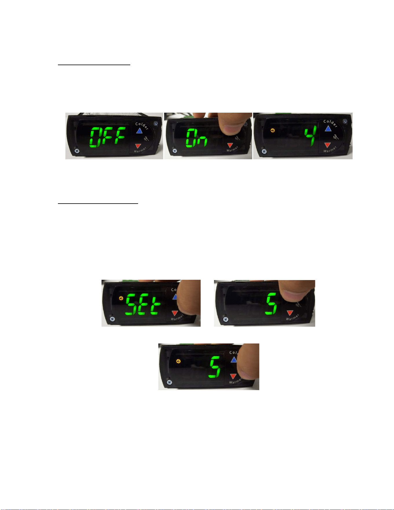
Powering on control
To turn power on to the refrigeration system press and hold, for three seconds, the blue up
arrow on the control’s keypad. The keypad will read “On” while the button is depressed. When
the system powers on, the display will read the current set point (a number “1” through “9”).
The orange compressor run indicator will illuminate on the display.
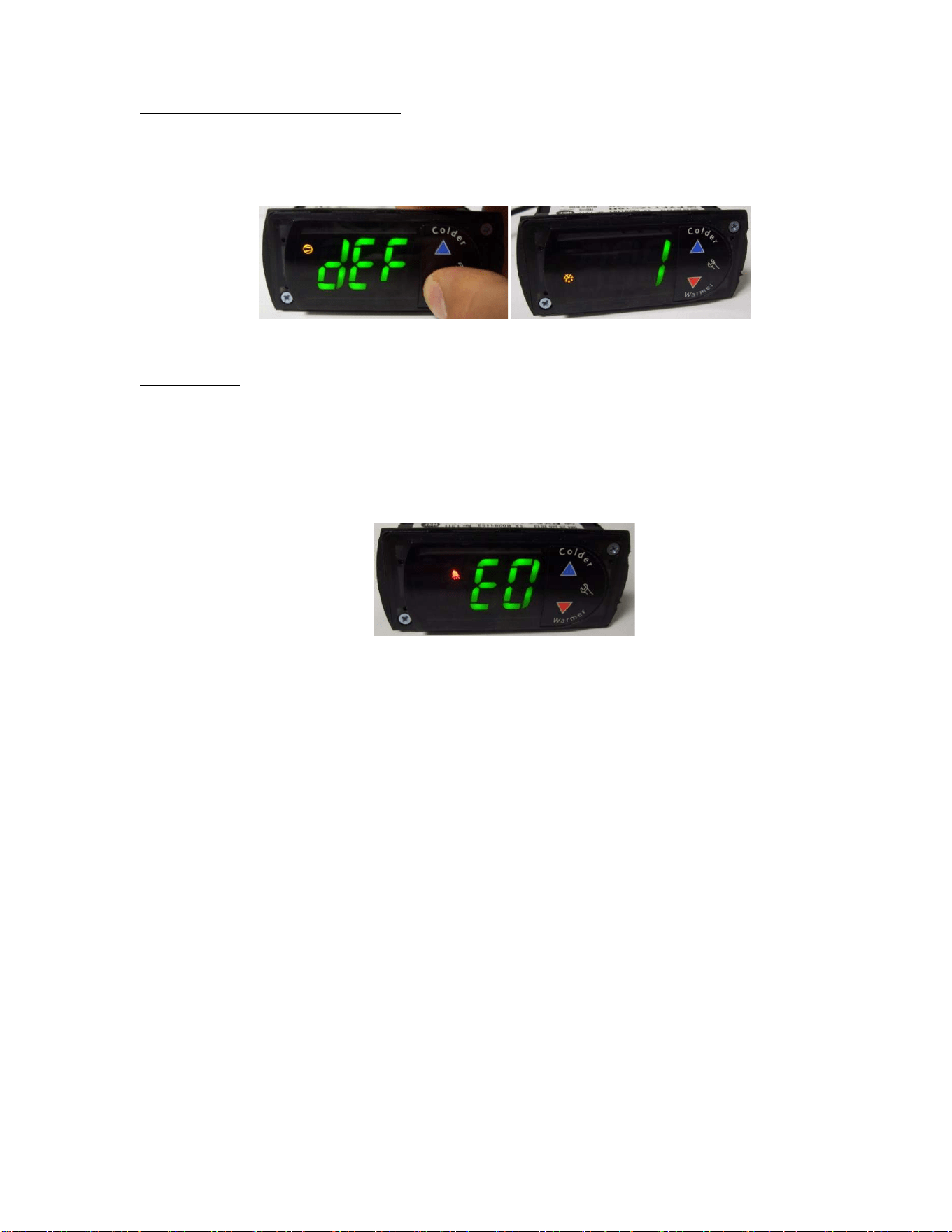
Adjusting the set point
The set point is what determines how cold the display case will hold food and beverage. To
adjust the set point press and hold the wrench button until the display begins to flash a number
(three seconds). Then use the up and down arrows of the keypad to scroll through the set point
options. There are nine (9) available set points, the higher the number of the set point name,
the colder the display case will run, with setting “9” being the coldest and setting “1” being the
warmest. Once you have chosen your desired setting press the wrench button again to confirm
your choice.
Page | 16
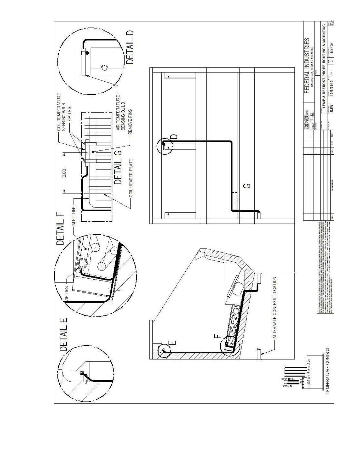
Entering manual defrost mode
In order to initiate a manual defrost press and hold the red down arrow for 3s. The control will
read “dEF” while the button is being held. The defrost is initiated when the orange snowflake
appears on the control display.
Error codes
It is possible for error codes to be displayed on the control screen. In the event of a malfunction
an alarm will sound and a red ringing bell will be displayed on the screen. An error code or
codes will flash intermittently on the display. If there are multiple codes, the display will
continuously cycle through them. The following photo shows error code “E0” as an example
next to the red bell.
You may mute the alarm by pressing and releasing the wrench button. The red ringing bell and
all error codes will still be displayed. When the fault is remedied the control will return to
normal operation and will automatically clear the codes from the display.
Page | 17
Page | 18
INITIAL STARTUP
After all the checks outlined in the installation section of this manual have been made, the case is ready to be
put into service. Turn on the Power at the breaker box and flip the Power Switch and Light Switch on unit to the
on position. Also ensure that the control is powered on as described above.
At start up from a warm unit, it is recommended that the temperature control is set to a warmer setting, such as
1. After the unit has gone through several cycles, adjust the control to a mid-range setting, then to a colder
setting if necessary to maintain desired product temperature
NOTICE:
This refrigerated display case is designed to operate in a maximum environment of
75°F (23.9°C) and 55% relative humidity. Exceeding these limits will cause poor
case performance and excessive sweating.
Placing Product in Case
Do not overload the case with product to a point where the top air discharge grill or the
bottom air intake grill are blocked or where the air curtain created by the discharge air is
blocked. The following diagram shows proper product loading.
Open refrigerated merchandisers are not intended as storage refrigerators and will not
“pull down” product that is warm or at room temperature. Load case interior with only
pre-chilled product.

Page | 19
Periodic Maintenance
IMPORTANT: Read this Section of this manual located on page 5.
“REFRIGERATION WARNING &INSTALLATION-REPAIR-DECOMMISSIONING”
All refrigeration and electrical work must be performed by certified technicians.
Cleaning Condenser Coil
Turn power switch “off”
Remove front grill on front air intake models, rear grill on rear intake models, and
vacuum the front surface of the condenser coil. Replace grill when done.
This should be done every one or two months as necessary.
Cleaning Case Interior
Turn power switch “off”
Clean interior surfaces with mild detergent and water. Do not use abrasive cleansers on
case interior.
Step pans or shelving may be removed from the case for easy cleaning.
Page | 20
SERVICE INFORMATION
Before any service work is performed on the case, make sure all power is disconnected to the
case.
IMPORTANT: Read this Section of this manual located on page 5.
“REFRIGERATION WARNING &INSTALLATION-REPAIR-DECOMMISSIONING”
All refrigeration and electrical work must be performed by certified technicians.
To find a service company in your area, please visit our website at
www.federalindustries.com. There you can also find self-service tools to help
you get the answers you need faster!
For Warranty Service Requests & ALL Technical Support please contact:
- Phone: (800) 356-4206 and choose the Tech Support/Warranty Option
- Email: [email protected]m
For Warranty Compressors please contact the Parts Department:
- Phone: (800) 356-4206 and choose the Warranty Parts Option
- Email: Parts@Federalind.com
Federal Industries has partnered with Parts Town for ALL Non-Warranty Part Identification,
Pricing, Lead Times, Orders & Freight Quotes. Please contact Parts Town directly if you need
parts:
- Website: PartsTown.com
- Email: CustomerService@PartsTown.com
- Phone: 833-809-8188
Page | 21
Pre-Service Checklist
You may avoid the cost and inconvenience of an unnecessary service call by first
reviewing this checklist of frequently encountered situations that can cause
unsatisfactory case performance.
Pre-Service Checklist
Case Does Not Operate
Check for disconnected power supply.
Check that power switch is “on”.
Case Temperature Too Warm
Check that top air discharge opening and/or bottom air intake grille are not
blocked.
Check for a blocked or dirty condenser coil.
Check that there are no outside air disturbances in or around case. These
disturbances can be caused by nearby doors or entrances, overhead ceiling fans,
or air diffuser vents, direct sunlight or other heat sources. The location of open
refrigerated merchandisers is critical to case performance.
Make sure that warm product is not being placed inside case. All products must
be pre-chilled prior to loading for proper case performance.
Check temperature/pressure control for proper settings.
Check cold air flow. Lack of, or no air flow may indicate a blocked evaporator coil
or defective evaporator fan motor. Contact a qualified service company if there is
no air flow inside the case.
Lights Do Not Operate (Optional Equipment)
Check that light switch is “on”.
Check that light bulb(s) are properly seated in light holders.
Overflow of Condensate Evaporator
Check that there is a power supply to the condensate evaporator assembly. On
self-contained models this is on a separate electrical circuit.
Check that the drain line is properly located over the water reservoir.
Check room ambient conditions. The room environment should not exceed 75F
ambient and 55% humidity conditions.
WARNING: Before servicing case turn off power at the
main breaker of fuse box.

Page | 22
Special Service Situations
IMPORTANT: Read this Section of this manual located on page 5.
“REFRIGERATION WARNING &INSTALLATION-REPAIR-DECOMMISSIONING”
All refrigeration and electrical work must be performed by certified technicians
There are rare occasions when the refrigerant charge must be evacuated from a case in
order to perform service work. In those situations, Federal Industries recommends that
the refrigerant charge be evacuated into a recovery system to prevent the possibility of
hydrochlorofluoracarbons (HCFC’s) from being released into the atmosphere. The
release of HCFC’s into the atmosphere is a potential source of global warming.
If moisture or liquid is observed around or under a Federal Industries case, an immediate
investigation should be made by qualified personnel to determine the source of moisture
or liquid. The investigation made should determine if the case is malfunctioning or if
there is a simple housekeeping problem.
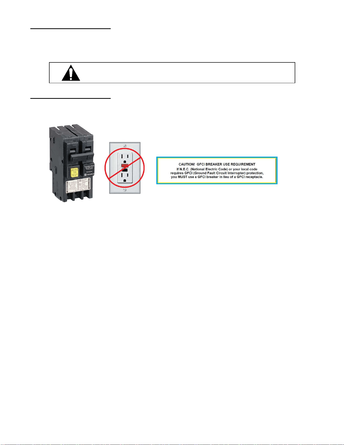
Moisture or liquid around or under a case is a potential slip/fall hazard for persons
walking by or working in the general area of the case. Any case malfunction or
housekeeping problem that creates a slip/fall hazard around or under a case should be
corrected immediately.
Page | 23
SALE & DISPOSAL
Owner Responsibility
IMPORTANT: Read this Section of this manual located on page 5.
“REFRIGERATION WARNING &INSTALLATION-REPAIR-DECOMMISSIONING”
All refrigeration and electrical work must be performed by certified technicians
If you sell or give away your Federal Industries case, you must make sure that all safety
labels and the Installation-Service Manual are included with it. If you need replacement
labels or manuals, Federal Industries will provide them free of charge. Contact the
Customer Service Department at Federal Industries at 1(800)356-4206.
The Customer Service Department at Federal Industries should be contacted at the time
of sale or disposal of your case so records may be kept of its new location.
If you sell or give away your Federal Industries case and you evacuate the refrigerant
charge before shipment, Federal Industries recommends that the charge be evacuated
into a recovery system to reduce the possibility of HCFC’s from being released into the
atmosphere. The release of HCFC’s into the atmosphere is a potential source of ozone
depletion.
Refrigerant Recovery/Recycling/Disposal
When recycling or discarding case, refrigerants MUST BE handled according to local,
state and federal codes, requirements and regulations.
If disposing of a refrigerated case that uses ozone depleting chemicals in its refrigeration
system, make sure the refrigerant is removed by a qualified service technician and
properly disposed of.
If you intentionally release refrigerant into the atmosphere, you may be subject to fines
or other penalties (under regulation mandated by environmental regulators and/or
legislative edict.)

Page | 24
REFRIGERATION & ELECTRICAL DATA
SELF-CONTAINED MODELS
RSS3SC-2B RSS4SC-2B
Model RSS3SC-3B RSS4SC-3B
Refrigerant R290 R290
ALL MODELS ARE 120 VOLTS, 1 PHASE, 60 HERTZ, 2 WIRE
AMPS AMPS
Compressor
RLA 9 8.3
LRA 32 41.5
Condenser 0.5 0.53
Fan Motor
Evaporator 0.2 0.2
Fan Ea. (2)
Anti-Sweat 0.1 0.1
Heater
Lights 0.26 0.26
Condensate 5.0 *10.0
Evaporator *(Separate Power Supply)
Condensate pump 1.0 1.0
(optional)
Refer to the rating plate data attached to the rear of the case for Maximum Fuse Size and Minimum
Circuit Ampacity.
Page | 25
REPLACEMENT PARTS
MODELS RSS3 & RSS4 INCLUDING HYBRID
Part Description Part Number
Refrigeration System RSS3 RSS4
Condensing Unit (Self-Contained Only) 30-21725 30-21726
Compressor (Replacement) 30-21725-COMP 30-21726-COMP
Refrigeration Control (Electronic) 32-19864-29 32-19864-29
Control Probe (2) 32-19866 32-19866
High Pressure Switch 32-21850 32-21850
Evaporator Coil 33-10946-20 33-50042-20
Expansion Valve 32-21751 32-21751
Evaporator Fan Motor 41-21572-10 41-21237-11
Toggle Switch 41-10974 41-10974
Anti-Sweat Heater 43-14892 43-14891
Terminal Block 45-11056 45-11056
Thermometer 32-13662 32-13662
Condensate Evaporator
Heating Element 600W 40-19331 40-19331
OBS Entire Assembly 600W SA5406-1 SA5406-1
Entire Assembly 600W replaces SA5406-1 SA5406-4 SA5406-4
Condensate Pan Bracket use with SA5406-4 M19017-4 qty 2 M19017-4 qty 2
OBS Entire Assembly 1200W SA5406-12 SA5406-12
Entire Assembly 1200W replaces SA5406-12 SA5406-15 SA5406-15
Condensate Pan Bracket use with SA5406-15 M19017-4 qty 2 M19017-4 qty 2
Condensate Steam Notice Tag 91-13038 91-13038
Optional Condensate Pump
Condensate Pump 120V 47-15686 47-15686
Hose 50’ 15-17337 50-17337
Standard Lights
LED Light 24V 42-20871-25C35 (2) 42-20871-38C35 (2)
Power Supply 24V 39-20986 39-20986
Light Clip 67-20869 (4) 67-20869 (4)
Light Switch 41-21765 41-21765
Cord LED 12” 43-20860-1B 43-20860-1B
SHELVING
Shelf Metal 10” M12738-3A M12738-2A
Shelf Metal 14” M12739-3A M12739-2A
Shelf Wire 10” 63-13904-1 63-13896-1
Shelf Wire 14” 63-13905-1 63-13897-1
Shelf Glass 10” 52-13616 52-15006
Shelf Glass 14” 52-13617 52-15007
Glass Shelf Clips 67-72582 67-72582
Shelf Bracket 10” 67-17732-1 67-17732-1
Shelf Bracket 14” 67-17732-2 67-17732-2
Shelf Standard M14679-2A M14679-2A
Wire Steps 63-11713 63-14961
Step Riser Bottom 5 ¼ x 18 ½ x length SA3124-1 SA3124-2
Step Riser Top 5 ¼ x 9 ¼ x length SA3123-1 SA3123-2
Step Riser Bottom 5 x 15 x length SA4079-1 SA4079-2
Step Riser Top 5x7 ½ x length SA4078-1 SA4078-2
Miscellaneous Components
Night Curtain 65-19459 65-19460
End Glass Clear 50-19414-1 50-19414-1
End Glass Reflective Right Hand 50-19414-3R 50-19414-3R
End Glass Reflective Left Hand 50-19414-3L 50-19414-3L
Anti-Sweat Heater 43-14892 43-14891
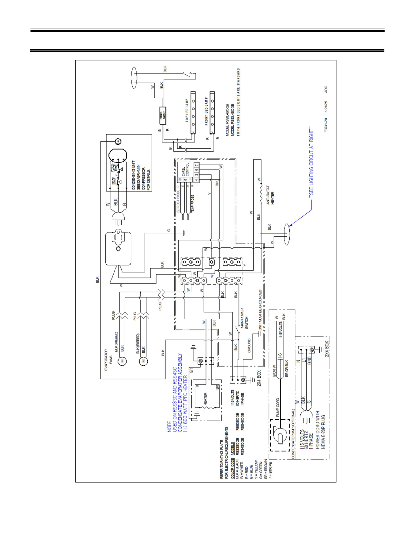
Page | 26
WIRING DIAGRAM- RSS3, 4 SC-2B & -3B

Page | 27
California Residents Only.
WARNING
This product can expose you to chemicals including chromium which is known to the State of California to
cause cancer and birth defects or other reproductive harm. For more information go to
www.P65Warnings.ca.gov
Page | 28
REV
CHANGE RECORD
APP’D
DATE
ECN#
0
RELEASED ADC 11/16/24 3933