
Installation and User Manual
RANGE HOODS
619, 621, 623,
625, & 627 MODELS
www.zlinekitchen.com

ZLINE Kitchen and Bath provides Attainable Luxury, where the kitchen and bath of your dreams
is never out of reach. Through our unique designs and unparalleled quality, we’re dedicated to
providing you an elevated experience in the heart of your home. With an endless selection of
features and finishes, our inspiration is your reality.

WARNING: This product can expose you to chemicals including nickel, which is known to the
State of California to cause cancer. For more information, go to www.P65Warnings.ca.gov.
ZLINE is fueled by a passion for innovation; A relentless pursuit of bringing the
highest end luxury designs and professional features into everyone’s homes.
Because we continually strive to improve our products, we may change
specifications and designs without prior notice.
Scan the QR code to view the most up-to-date version of the Installation
Manual and User Manual.

IMPORTANT SAFETY INSTRUCTIONS . . . . . . . . . . . . . . . . . . . 1
BEFORE INSTALLATION . . . . . . . . . . . . . . . . . . . . . . . . . . . . . . . 4
Product Specifications . . . . . . . . . . . . . . . . . . . . . . . . . . . . . . . 5
Product Dimensions . . . . . . . . . . . . . . . . . . . . . . . . . . . . . . . . 6
Ventilation And Clearances . . . . . . . . . . . . . . . . . . . . . . . . . . . 10
INSTALLATION . . . . . . . . . . . . . . . . . . . . . . . . . . . . . . . . . . . . . 14
Installation Options . . . . . . . . . . . . . . . . . . . . . . . . . . . . . . . 14
Baffle Filters . . . . . . . . . . . . . . . . . . . . . . . . . . . . . . . . . . . 16
OPERATION . . . . . . . . . . . . . . . . . . . . . . . . . . . . . . . . . . . . . . . 17
Fan Speed And Light Controls . . . . . . . . . . . . . . . . . . . . . . . . . 17
CLEANING AND MAINTENANCE . . . . . . . . . . . . . . . . . . . . . 21
TROUBLESHOOTING . . . . . . . . . . . . . . . . . . . . . . . . . . . . . . . . 23
WARRANTY . . . . . . . . . . . . . . . . . . . . . . . . . . . . . . . . . . . . . . . . 24
TABLE OF CONTENTS

1
IMPORTANT SAFETY INSTRUCTIONS
General Safety
WARNING
If the information in this manual is not followed exactly, a fire or explosion may
result causing property damage, personal injury, or death.
• Before beginning installation, please read and follow these important instructions for the
safety of your home and the people living in it.
• The instructions in this manual are intended for qualified installers and certified service
technicians. Installation and electrical wiring must be completed by qualified professionals
and in accordance with applicable codes and standards.
• DO NOT attempt to install this appliance yourself. Injury could result from installing the
unit due to lack of appropriate electrical and technical background.
• The installer should leave these instructions with the consumer who should retain for local
inspectors’ use and for future reference.
• Due to the size and weight of ZLINE range hoods, two-person installation is highly
recommended.
• Use care when handling the range hood, chimney cover, baffle filters, and any parts or
accessories, as sharp edges may lead to injury. Use of gloves during installation is highly
recommended.
• The manufacturer will not be responsible for any damage to property or to persons
caused by incorrect installation, improper use of the appliance, or failure to heed the
warnings listed.
• The manufacturer reserves the right to make changes to its products when considered
necessary and useful, without affecting the essential safety and operating characteristics.
• This appliance is designed for general ventilating use only. DO NOT use to exhaust
hazardous or explosive materials and vapors.
• The combustion air flow needed for safe operation of fuel-burning equipment may
be affected by this unit’s operation. Follow heating equipment guidelines and safety
standards such as those published by the National Fire Protection Association (NFPA),
American Society of Heating, Refrigeration and Air Conditioning Engineers (ASHRAE),
and local code and government authorities.
• Sufficient air is needed for proper combustion and exhausting of gases through the
ducting installed with range hoods to prevent back drafting.
• Before servicing or cleaning the unit, fully disconnect the hood from power to avoid risk
of electric shock and injury.

2
IMPORTANT SAFETY INSTRUCTIONS
General Safety
• Ducted range hoods MUST ALWAYS be vented to the outdoors or in some instances
converted to recirculate the air. All ZLINE hoods come with a transition piece with a
built-in damper.
• Some existing installations may already have an external damper at the exit point of the
home. In this case, the damper in the transition piece of your hood needs to be removed,
as these two dampers work against each other and will reduce the performance
of the hood.
• Please consult an HVAC or installation professional for advice to comply with local
regulations and ensure appropriate ventilation.
• When cutting or drilling into a wall or ceiling, be careful not to damage electrical wiring
or other hidden utilities.
• All electrical wiring must be properly installed, insulated, and grounded. A 120 VAC,
60 Hz, AC-only fused electrical supply is required on a separate 15-amp circuit, fused
on both sides of the line.
• Electrical installation must be in accordance with the National Electrical Code ANSI/
NPA70-latest edition and/or local codes.
• Old duct work should be cleaned or replaced, if necessary, to avoid the possibility of a
grease fire or other hazard. Check all joints on duct work to ensure proper connection;
all joints should be properly taped/secured.
• When a range hood ventilates air out of the room, the vented air must be replaced; this
is called makeup air. If a makeup air system is needed, but not used, a hood may not
function as expected due to negative air pressure.
• ZLINE does not currently provide makeup air units. Always consult applicable building
codes regarding minimum and maximum air flow rates. Certain states may require
additional items such as makeup air for larger CFM range hoods.
• Keep the motor, fans, baffle channels, filters, tunnels, cups, and grease-laden surfaces
clean. Grease should not be allowed to accumulate inside or on the surface of the range
hood; clean surfaces frequently.
• Take care when cleaning the range hood in spray form: never direct spray of water or
cleaners onto the electrical wiring, motor, button panel, or light bulbs.
• After installation, use a stainless steel cleaning product or wipe to eliminate any residues
from protective film after removal.

3
IMPORTANT SAFETY INSTRUCTIONS
General Safety
• When cleaning stainless steel, only use a stainless steel cleaner product with a soft
sponge, or use a cloth with a warm soap and water solution. Never use abrasive
powders or liquids.
• To reduce the risk of fire and to disperse air properly, make sure to vent air outside.
DO NOT vent exhaust into spaces between walls, crawl spaces, ceilings, attics,
basements, or garages.
• All ZLINE range hoods are ETL-listed, ensuring all parts were tested for safety and meet
industry standards and regulations.
• You must purchase appropriate flexible ducting and any additional items to vent the
hood in accordance with government codes.
• Please verify with local and state regulations on the proper venting method for your
hood. Many agencies have CFM rating specifications for your hood.
• Always turn the range hood on when cooking at high heat or when cooking flaming
foods. Use high settings on the cooking range below only when necessary.
• Never leave range top surface units underneath a range hood unattended at high
settings. Boilovers can cause smoking and greasy spillovers that may ignite. Heat oils
slowly on low or medium settings.
• Always use appropriate cookware and utensils; always use cookware appropriate for
the size of the surface element on your range top underneath a range hood.
• To reduce the risk of injury in the event of a range top grease fire, smother flames with
a close fitting lid, cookie sheet, or metal tray, then turn off the burner. Never pick up a
flaming pan — you may be severely burned.
• Keep flammable or combustible material away from flames. If flames do not go out
immediately, evacuate and call the fire department. DO NOT use water, including wet
dishcloths or towels — a violent steam explosion will result.
• Carefully inspect all items for damages upon delivery. Upon acceptance of the range
hood, owner assumes responsibility for its safe arrival.
• Before installing your unit, test the range hood for proper functionality by plugging it into
an appropriate outlet and testing the fan and lights. Do not install any appliance if they
have missing or broken parts. If units arrive damaged, contact ZLINE Customer Service
at 1-614-777-5004 for help.
4
BEFORE INSTALLATION
TOOLS NEEDED
• Marker or pencil
• Utility knife
• Measuring tape
• Level
• Powered drill
• Flat-blade and Phillips screwdrivers
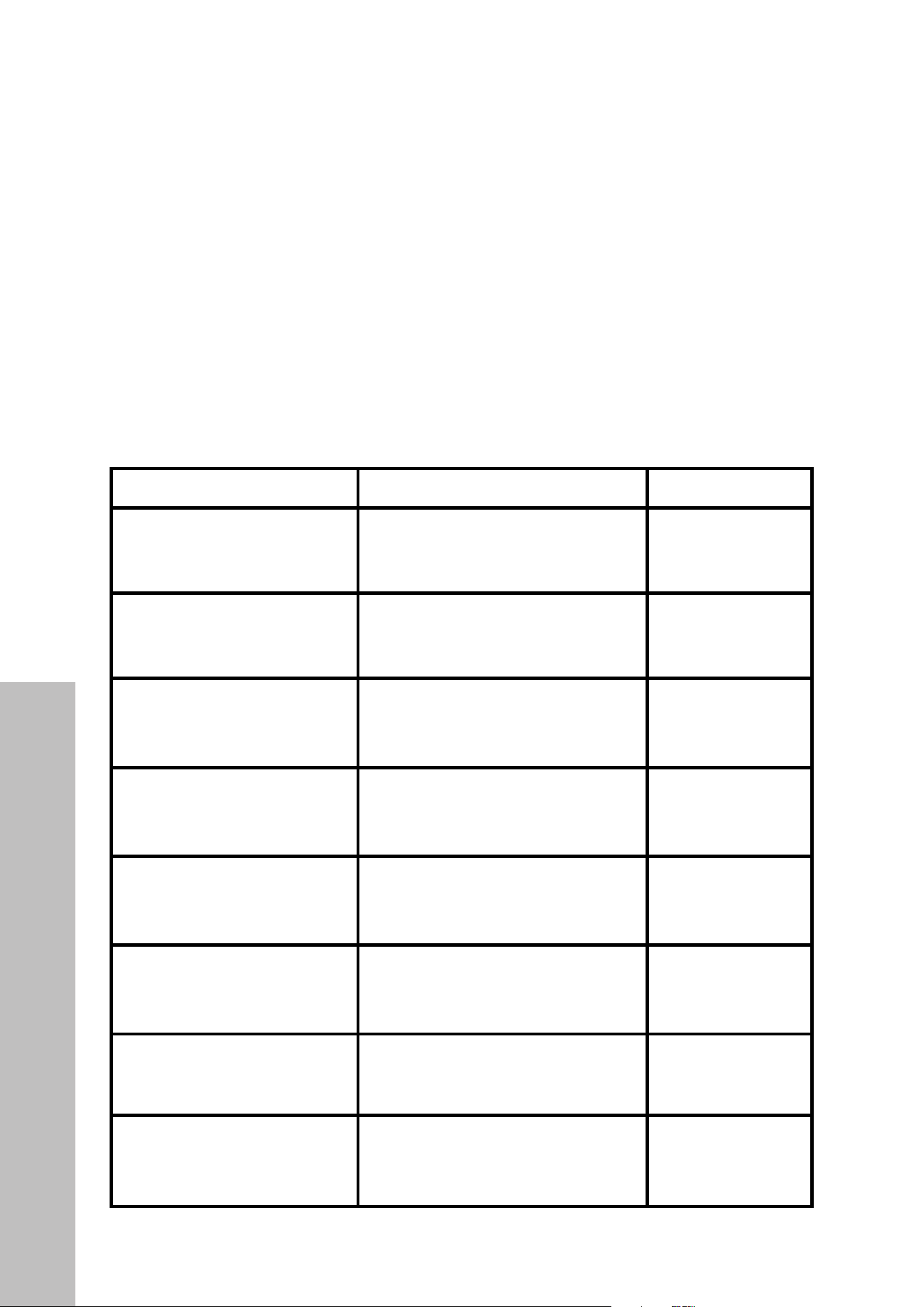
PARTS SUPPLIED
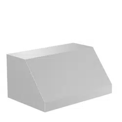
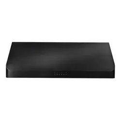
DESCRIPTION IMAGE QTY
Undercabinet Range Hood
1
Baffle Filter Spacer
varies
Baffle Filter
varies
Wall Mount Anchors
4
Wall Mount Screws
4
Mounting Bracket Screws
6
Mounting Bracket
1
Grease tunnel
1
Parts
5
BEFORE INSTALLATION
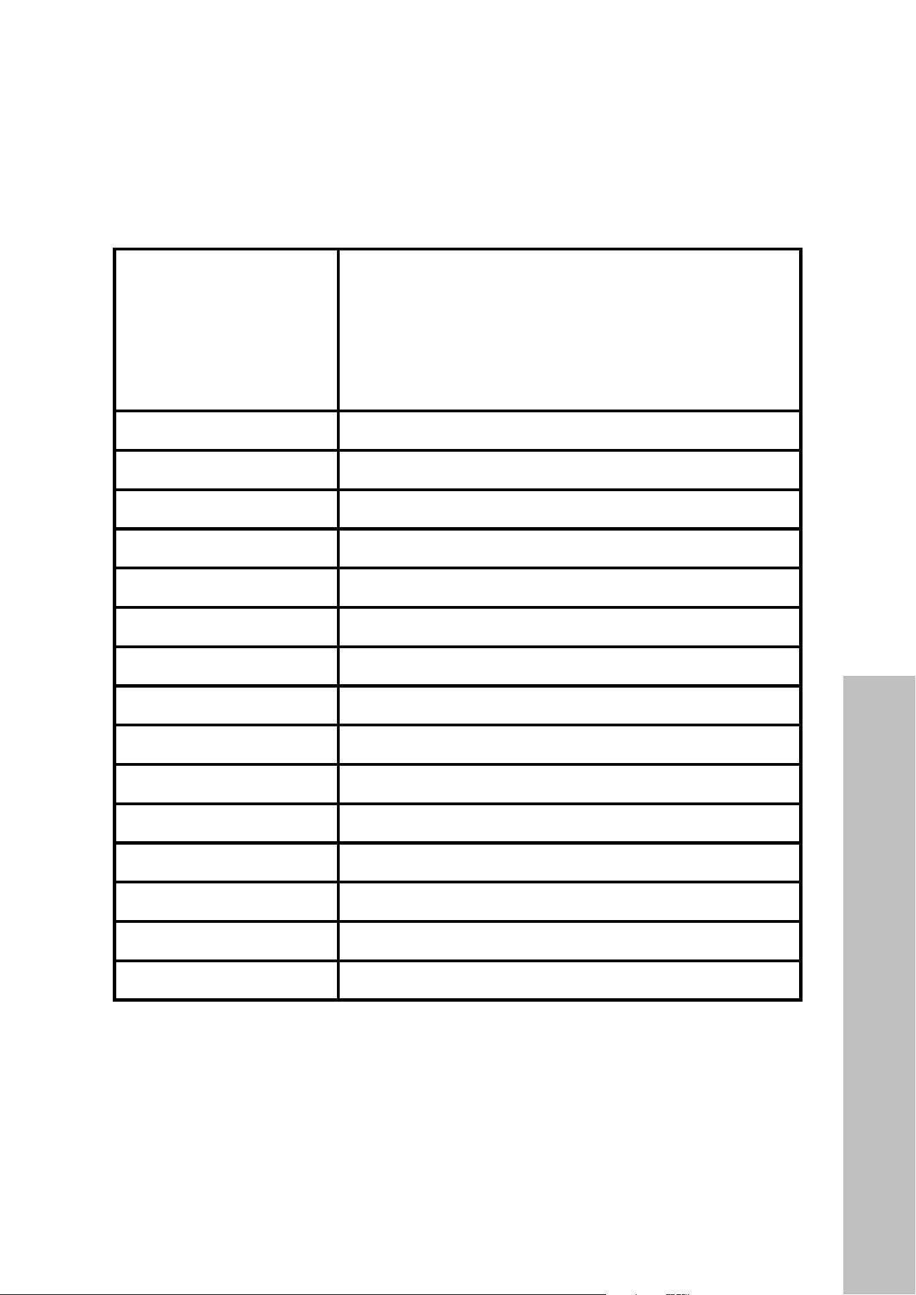
PRODUCT SPECIFICATIONS
Models
619 Series: 619-30, 619-36, 619-42, 619-48
621 Series: 621-30, 621-36, 621-42, 621-48
623 Series: 623-30, 623-36, 623-42, 623-48
625 Series: 625-30, 625-36, 625-42, 625-48
627 Series: 627-30
Body Design Seamless Stainless Steel, Satin Finish
Power Rating 120V/60Hz (USA & Canada standard)
General Input Power 300 W (260 + 2x20W)
Motor Input Power 260 W (130W + 130W)
Ampere 3A
Levels Of Speed Control 4 Levels
Airflow (Q/L/M/H) 270CFM / 380CFM / 490CFM / 600CFM
Number Of Motors Dual Motors
Motor Type Single Chamber Ultra Quiet
Fan Type Centrifugal Squirrel Cage
Control Type Touch Sensitive Electronic Control Panel w/ LED Display
Filtration Type Stainless Steel Baffle Filters
Illumination 20W, 12V Maximum, Dual Intensity
Venting Size Top Transition, 7" (178mm) Round
Interference Protection Radio Frequency Interference Protected
Product Specifications
6
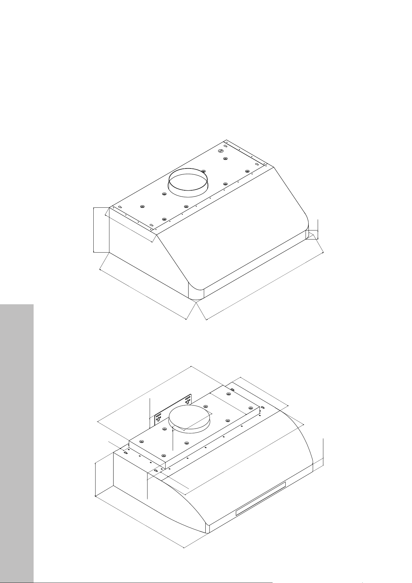
BEFORE INSTALLATION
PRODUCT DIMENSIONS
619 Series (Models 619-30, 619-36, 619-42, 619-48)
623 Series (Models 623-30, 623-36, 623-42, 623-48)
2 3/8"
(50 mm)
9 13/16" (250 mm)
12" (305 mm)
22 1/16" (560 mm)
30"/36"/42"/48"
(762 mm/914 mm/1067 mm/1219 mm)
621 Series (Models 621-30, 621-36, 621-42, 621-48)
625 Series (Models 625-30, 625-36, 625-42, 625-48)
1 1/2" (38 mm)
7" (178 mm)
22" (559 mm)
12" (305 mm)
9 5/16" (236 mm)
1 5/8" (41 mm)
30"/36"/42"/48"
(762 mm/914 mm/1067 mm/1219 mm)
Ø6 13/16 (173 mm)
30" Models: 23 5/8" (600 mm)
36"/42"/48" Models: 29 5/8 (752 mm)
1 13/16 (46 mm)
2 3/16" (56 mm)
13/16"
(20 mm)
1 7/8" (48 mm)
Product Dimensions
7
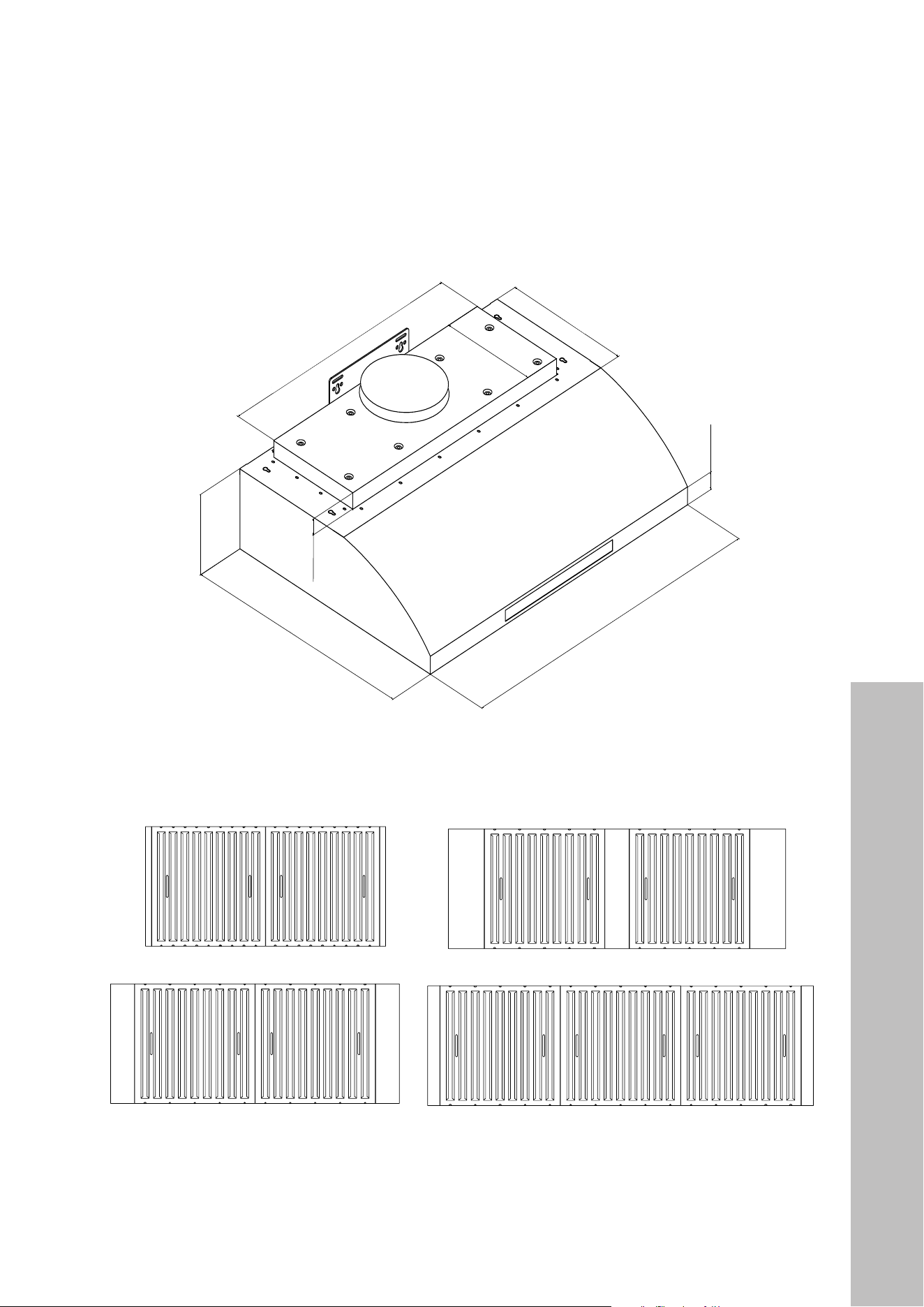
PRODUCT DIMENSIONS
627 Series (Model 627-30)
1 1/2" (38 mm)
7" (178 mm)
22" (559 mm)
12" (305 mm)
9 5/16" (236 mm)
1 5/8" (41 mm)
30"/36"/42"/48"
(762 mm/914 mm/1067 mm/1219 mm)
30" Models: 23 5/8" (600 mm)
36"/42"/48" Models: 29 5/8 (752 mm)
BAFFLE FILTER SIZES
48" Models
42" Models
36" Models
30" Models
BEFORE INSTALLATION
Product Dimensions

8
Product Dimensions
BEFORE INSTALLATION
PRODUCT DIMENSIONS
Rear knockout hole dimensions
9" (228 mm)
9" (228 mm)
11/16" (18 mm)1 3/8" (35 mm)
7/8" (23 mm)
4 3/4" (120 mm)
3/8" (9 mm)
8 5/8" (220 mm)
10 1/4" (260 mm)
12" (304 mm) for 30" Range Hood
3" (75 mm)
3" (75 mm)
3" (75 mm)
3" (75 mm)
18" (456 mm) for 36" Range Hood
24" (724 mm) for 42" Range Hood
30" (760 mm) for 48" Range Hood
Hood-mounting bracket dimensions
9" (228 mm)
9" (228 mm)
11/16" (18 mm)1 3/8" (35 mm)
7/8" (23 mm)
4 3/4" (120 mm)
3/8" (9 mm)
8 5/8" (220 mm)
10 1/4" (260 mm)
12" (304 mm) for 30" Range Hood
3" (75 mm)
3" (75 mm)
3" (75 mm)
3" (75 mm)
18" (456 mm) for 36" Range Hood
24" (724 mm) for 42" Range Hood
30" (760 mm) for 48" Range Hood
9
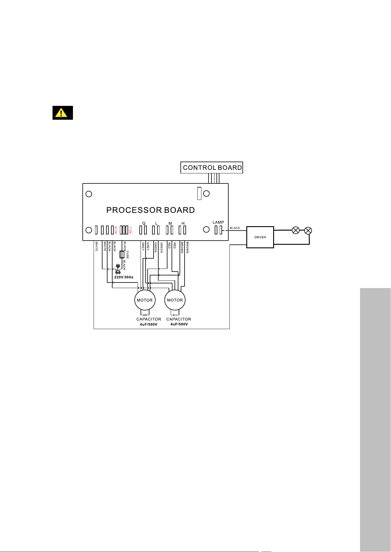
Electrical Requirements
CIRCUIT DIAGRAM
WARNING
Risk of electrical shock. This range hood must be properly grounded by a qualified
electrician in accordance with all applicable national and local electrical codes.
Before connecting wires, switch power off at the service panel and lock it to
prevent power from being switched on accidentally.
48" Models
42" Models
36" Models
30" Models
NOTES:
• The range hood must be connected with copper wire/plug only.
• The range hood should be connected directly to the fused disconnect (or circuit breaker)
box through flexible armored or non-metallic sheathed copper cable. UL/CSA listed
strain relief must be provided at each end of the power supply cable.
BEFORE INSTALLATION

10
BEFORE INSTALLATION
VENTILATION AND CLEARANCES
4
Under Cabinet
Range Hood
Cabinet or Single-Piece
Chimney (Optional)
Countertop/Stove
Halogen light
glass cover
1
Halogen light
housing
Flat headed
screwdriver
Halogen light
bulb 12V 20W
2 3
36"
Counter
Top
Ceiling
Height
Min: 30"
Max: 36"
Range
Hood
Height
Cabinet
Height
NOTE: The recommended
height to install your hood is 30"
(762 mm) minimum and 36"
(914 mm) maximum above your
range top or cook top. These
distances allow for optimal
venting efficiency. Consult an
HVAC or installation professional
for ventilation advice.
Ventilation and Clearances

11
BEFORE INSTALLATION
VENTING REQUIREMENTS
• Determine the location of the venting pipe from the hood to the outside of your home
before installation.
• Ducting is not provided with your ZLINE range hood. It’s recommended to use solid
ducting made of galvanized steel or another appropriate rigid metal ducting whenever
possible for the lowest noise and highest flow.
• Use a maximum of 40' (12192 mm) of ductwork. Try to minimize the use of elbows.
• You must establish a minimum of 12" (305 mm) of vertical airflow from the top of the hood
before executing any 90° turn. No more than 3 elbows are allowed; each 90° turn you
make equates to 5' (1524 mm) lost when accounting for the maximum 40' (12192 mm).
• DO NOT install two elbows together. If turns or transitions are required, install them as
far from the hood as possible.
• Do not use any reducers on ducting smaller than the appropriate diameter for your
hood’s transition piece, which is 7" (178 mm) for 600 Series models.
• Any existing or additional dampers should be inspected for proper operation.
• The size of the vent should be uniform or larger than the cooking surface below.
• Always keep the duct clean to ensure proper airflow.
FOR THE MOST EFFICIENT AND QUIET OPERATION
• It is recommended that the range hood be vented vertically through the roof with a
minimum of a 7" (178 mm) or larger vent work.
• ALWAYS, when possible, reduce the number or transitions and turns. If long duct run is
required, you may increase duct size from 7" (178 mm) to 8" (203 mm) or 9" (229 mm).
If a reducer is used, install a long reducer instead of a pancake reducer.
• A minimum of 7" (178 mm) round (standard for this range hood) or 3-1/4 x 10"
(254 mm) rectangular duct (purchased separately) must be used to maintain maximum
airflow efficiency.
• Always consult an HVAC or installation professional to determine the best ducting option
for your range hood, as each kitchen and home layout will vary.
Venting Requirements

12
Venting Methods
BEFORE INSTALLATION
VENTING METHODS
This range hood is factory set for venting through the roof or wall. Vent work can terminate
either through the roof or wall. To vent through a wall, use a 90° elbow. Below are examples
of appropriate ducting options.
1
2
3
4
5
6
7
3
9
8
10
11
12
13
14
15
17
17A
17B
17C
17D
18
22
23
19
20
21
16
Side Wall Cap
Option 1 Option 2
Horizontal Wall Venting
Vertical Wall Venting
Roof Cap
1
2
3
4
5
6
7
3
9
8
10
11
12
13
14
15
17
17A
17B
17C
17D
18
22
23
19
20
21
16
Side Wall Cap
Option 1 Option 2
Horizontal Wall Venting
Vertical Wall Venting
Roof Cap
IMPORTANT SAFETY ALERTS
• NEVER exhaust air or terminate duct work into spaces between walls, crawl spaces,
ceiling, attics or garages. All exhaust must be ducted to the outside.
• Use metal/aluminum duct work only.
• Fasten all connections with sheet metal screws and tape all joints with certified
silver tape.
• Use caulking to seal exterior wall or roof opening around the cap.
• DO NOT terminate the vent system in an at tic or other enclosed area.
• DO NOT use 4" (102 mm) laundry-type wall caps.
• DO NOT use plastic ventilation.
WARNING

13
BEFORE INSTALLATION
WARNING
To avoid damage to your hood or potential future injury, use care to prevent any
debris from entering the vent opening.
4" (102 mm) wide 4" (102 mm) wide
Figure 1 Figure 2
Prior to installation, determine the location of the venting pipe from the hood to the outside.
Refer to “Venting Requirements” on page 11. Additionally, use care to peel off the white
plastic protective coat off the hood, if any.
You have two options to install your under cabinet range hood:
• OPTION 1: Securing the hood directly to the bottom of the cabinet above.
• OPTION 2: Securing the hood to the wall using the provided Wall Mount Bracket.
NOTES:
• If using Option 1 and installing under the cabinet with a recessed bottom, attach
4" (102 mm) wide wood filler strips (not provided) on each side. Refer to Figure 1 above.
• Additionally, you will need to knock out the screw holes located on the left and right side
of the top of the hood as shown in Figure 2.
WARNING
If moving an electric cooktop or induction range below the hood is necessary to
install, unplug the unit and turn off power at the circuit board. If moving a gas-
powered range, additionally make sure to completely shut off the gas supply.
WARNING
Using either option, use care to ensure the hood is secure to the cabinet or wall
before releasing to avoid risk of the hood falling and/or personal injury.
Installation Preparation

14
INSTALLATION OPTIONS
INSTALLATION - OPTION 1
1. Measure the distance between stove top and the bottom of range hood. A distance of
30" to 36" (762 mm to 914 mm) is recommended. Center the hood beneath the cabinet
so it is flush with the front of the cabinet.
2. Draw electrical wires through the opening at the back of the hood, as shown in Figure 4.
3. Using a second person to hold the hood in place, secure the hood to the bottom of the
cabinet using the provided six Mounting Bracket Screws. From inside of the hood, place
screws into the exact center of each knockout hole and secure to cabinet bottom.
4. Finish tightening all screws until secure. You may use additional screws if desired to
secure further. Be careful when using an electrical screwdriver, as damage to the range
hood may occur if you over-tighten.
INSTALLATION - OPTION 2
1. Measure the distance between stove top and the bottom of range hood and draw
electrical wires through the back of the hood as outlined in Figure 4 below.
2. Using a level, mark the final resting location for the Mounting Bracket and use a
pencil or marker to mark two drill holes through the brackets.
3. Pre-drill the two holes into the wall. It’s recommended to mount to a secure backing, such
as wood studs, to hold the weight of the hood.
4. If not drilling into studs, use the provided Wall Mount Anchors. Secure the two Wall
Mount Screws on the wall, leaving 1/8" (3 mm) space away from the wall. See Figure
5. Using the six provided Mounting Bracket Screws, attach the bracket to the back of the
hood, as outlined in Figure 3.
5. Use a second person to hold the hood in place while you align the Mounting Bracket to
the partially fastened screws on the wall, as outlined in Figure 5.
6. Fully secure the mounting screws through the Mounting Bracket into the wall.
Figure 3 Figure 4 Figure 5
INSTALLATION
Installation Options

15
FINAL INSTALLATION STEPS
1. Once the hood is secure, attach the appropriate ducting for your hood to the ducting
transition piece on top of the hood. See Figure 6 below.
2. Connect the range hood to a designated standard outlet (120-VAC, 60Hz, AC only) or
cut off the plug and connect three wires (black, white, green) to house wires and secure
with wire connectors/wire nuts. Connect according to color (black to black, white to
white, green to green) as shown in Figure 7.
3. Drop the oil tunnel into recess support near rear of hood. See Figure 8.
Figure 7
Figure 8
Figure 6 Figure 9
5
3
2
1
4
INSTALLATION
Final Steps
16
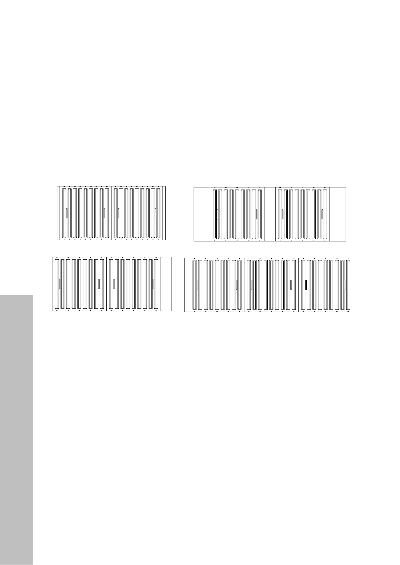
Baffle Filters
INSTALLATION
4. To install baffle filters and stainless spacer(s), refer to the images below and Figure 9 on
the previous page: Angle the baffle filter toward the back of hood. Push the filter up until
almost level. Slide forward into recess behind the front of hood. Lower the filter and slide
back until it fits into resting positions.
BAFFLE FILTERS
48" Models
42" Models
36" Models
30" Models

17
BUTTON PANEL FUNCTIONS - LAYOUT 1
Digital Timer
Speed Indicator
Power-Off Delay Control
Light Control
Speed Control
Power Control
(On/Off)
FAN SPEED AND LIGHT CONTROLS
In this button panel layout, four touch-sensitive electronic buttons control the intensity of the
Lights, Speeds (Quiet, Low, Medium and High), Power-Off Delay and Power (On/Off).
The Power-Off Delay offers an up-to 60-minute delay shutoff. The Power (On/Off) button
controls immediate startup or shutoff. The Light Control operates independently from the
Power Control (On/Off) and is not affected by the delay shutoff.
Always tum fans on before cooking to establish air flow and allow fans to run for a few
minutes after cooking for cleaner air in the kitchen. The Power Control (On/Off) button must
be pressed before a Speed Control button can be activated.
• Touch the Power Control (On/Off) button once. The Digital Timer on the left will flash. If
a Speed Control button is not touched within 10 seconds, power will automatically turn
off. NOTE: The light setting will not be affected by the Power Control (On/Off) button.
• Touch a Speed Control button once to activate the fan at high speed (H) and once again
to activate medium speed (M). Each touch will cycle through high (H), medium (M), low
speed (L) and Quiet (Q). The Speed Indicator on the left will light up accordingly.
60-MINUTE DELAY
• While the fans are operating, touch the Power-Off Delay Control button once. The Digital
Timer will flash for a few seconds, and fans will shut off after 3 minutes (default).
• To adjust the time delay, while the fans are operating, touch Power-Off Delay Control
once. The Digital Timer on left will flash for few seconds — while flashing, touch Power-
Off Delay Control again to increase time by 1 minute, up to 60 minutes total.
• During this 60-minute delay, changing speeds will not affect the countdown. The Power-
Off Delay Control will only tum off fans. The light settings will not be affected by the
delay function.
OPERATION
Fan Speed Controls

18
Light Controls
IMMEDIATE POWER-OFF
• Touch Power Control (On/Off) twice and the fans will be turned off immediately.
LIGHT CONTROL
The Light Control button operates independently from the Power Control (On/Off) and
Power-Off Delay Control buttons. Touching the Power Control (On/Off) button or activating
the delay function will not tum lights on or off. Lights have three settings: High, Low and Off:
• Press the Light Control button once to turn lights on at High intensity. The LED Light
Indicator will light up.
• Touch the Light Control button again to change the light intensity to Low.
• Each touch of the Light Control button will cycle the light intensity through High,
Low, and Off.
DO NOT touch the lights until switched OFF and cooled.
BUTTON PANEL FUNCTIONS - LAYOUT 2
Light Control Speed Control Power Control
(On/Off)
LED Speed
Indicators
LED Light
Indicator
In this button panel layout, six electronic buttons control the intensity of the Lights, Speeds
(Quiet, Low, Medium and High) and Power (On/Off). The Power Control (On/Off) button
offers startup, 3-minute delay or immediate power-off options. The Light Control operates
independently from Power Control (On/Off) and is not affected by the delay shutoff.
OPERATION
WARNING

19
OPERATION
Fan Speed Controls
FAN SPEED CONTROLS
Always turn fans on before cooking to establish air flow and allow fans to run for a few
minutes after cooking for cleaner air in the kitchen. The Power Control (On/Off) button must
be pressed before a Speed Control button can be activated:
• Press the Power Control (On/Off) button once. The four LED Speed Indicators above
the Speed Control will flash. If a Speed Control button is not pressed within 10 seconds,
power will turn off automatically.
• While the LED Speed Indicators are flashing, press a Speed Control button to activate
the desired speed, rotating from Quiet, Low, Medium and High speeds, as outlined in the
diagram below. For each speed, the LED Speed Indicator above the button will light up.
• To change the fan speed, press another Speed Control button. The LED Speed Indicator
above the new speed button will light up accordingly.
Light Control
Quiet
Speed
Low
Speed
Medium
Speed
High
Speed
Power Control
(On/Off)
LED Speed
Indicators
LED Light
Indicator
3-MINUTE DELAY
• While fans are operating, press the Power Control (On/Off) button once. The LED Speed
Indicators for the active power level will flash, and fans will turn off after 3 minutes.
• During the 3-minute delay, changing speeds will not affect the countdown.
• NOTE: The 3-minute delay function will only turn off fans. Light settings will not be
affected by the delay function.

20
Light Controls
OPERATION
IMMEDIATE POWER-OFF
• While the fans are in 3-minute power-off delay mode, press the Power Control (On/
Off) button once to tum off the fans immediately.
• When the fans are operating in normal mode (LED Speed Indicator not flashing), press
the Power Control (On/Off) button twice to tum off the fans.
LIGHT CONTROL
The Light Control button operates independently from the Power Control (On/Off) button
and the power-off delay function. Pressing the Power Control (On/Off) button or activating
the delay function will not tum lights on or off. Lights have three settings: High, Low and off:
• Press the Light Control button once to turn lights on at High intensity. The LED Light
Indicator will light up.
• Touch the Light Control button again to change the light intensity to Low.
• Each touch of the Light Control button will cycle the light intensity through High,
Low, and Off.
DO NOT touch the lights until switched OFF and cooled.
HEATING LAMP CONTROL
Heating lamps are sold separately (120-Volt, 250-Watt maximum). Heating lamps operate
independently from the electronic controls. Pressing the Power Control (On/Off) button,
Light Control button or activating the delay function will not affect the heating lamps. Heating
lamps are controlled by a switch located at the right side next to the halogen light:
• To turn on the heating lamps, switch the control to the on position.
• To turn off the heating lamps, switch the control to the off position.
WARNING
DO NOT touch the heating lamps until switched off and cooled.
NOTE: While some range hood models, depending on manufacture date, may have
different button layouts, operation is largely the same.
WARNING

21
Cleaning Tips
CLEANING AND MAINTENANCE
WARNING
Never clean the range hood while the power is on. Always unplug the unit or
switch the electrical breaker to the off position. Do not put your hand or body
parts inside the hood’s motor while in operation. Do not operate the hood when
filters are removed. Never disassemble parts to clean without proper instructions.
CLEANING TIPS
• Over time, saturation of oily and greasy residue in the motor, baffle filters, grease tunnel,
or on the underside of the range hood itself may cause increased inflammability.
• For optimal operation, clean all of these parts on a consistent basis. Regular care will
help preserve the appearance of the range hood.
• Clean with a stainless steel cleaner or hot soapy water and a cotton-based cloth. Do
NOT use corrosive or abrasive detergents (e.g. Comet Power Scrub
®
or EZ-Off
®
oven
cleaner) or steel wool/scouring pads, as these will scratch and damage the stainless
steel surface. For heavier grease and soil, use a kitchen-safe liquid degreaser such as
“Formula 409
®
” or “Fantastic
®
” brand cleaner.
• If the hood looks splotchy, use a stainless steel cleaner to clean the surface of the hood.
Avoid getting cleaning solution on or into the control panel. Follow directions of the
stainless steel cleaner. Do not leave on too long as this may damage the hood finish.
• After cleaning, use a non-abrasive stainless steel polish to polish and buff out the stainless
luster and grain. Always scrub lightly with a clean cotton cloth and with the grain.
• Do NOT allow grease or food deposits to accumulate or remain on the hood.
• Do NOT allow salt solutions, disinfectants, bleaches, or cleaning compounds to contact
stainless steel for extended periods. Many of these compounds contain chemicals that
may be harmful. Rinse with water after exposure and wipe dry with a clean cloth.
• When cleaning the oil tunnel and stainless steel baffle filters, it’s important to drain excess
oil and grease to avoid oil and residue overflow.
• Stainless steel baffle filters are intended to filter out residue and grease from cooking.
They do not need to be replaced on a regular basis but are required to be kept clean.
• Filters should be cleaned after every 30 hours of use. Remove and clean by hand, or
you can clean in a dishwasher, as the baffle filters are dishwasher-safe.
• Use an appropriate degreasing detergent for stainless steel and leave the filters to soak
for an extended period if they are heavily soiled. Use a dry cloth to completely dry the
filters before re-installing them on the hood.
22
Replacing Light Bulbs
CLEANING AND MAINTENANCE
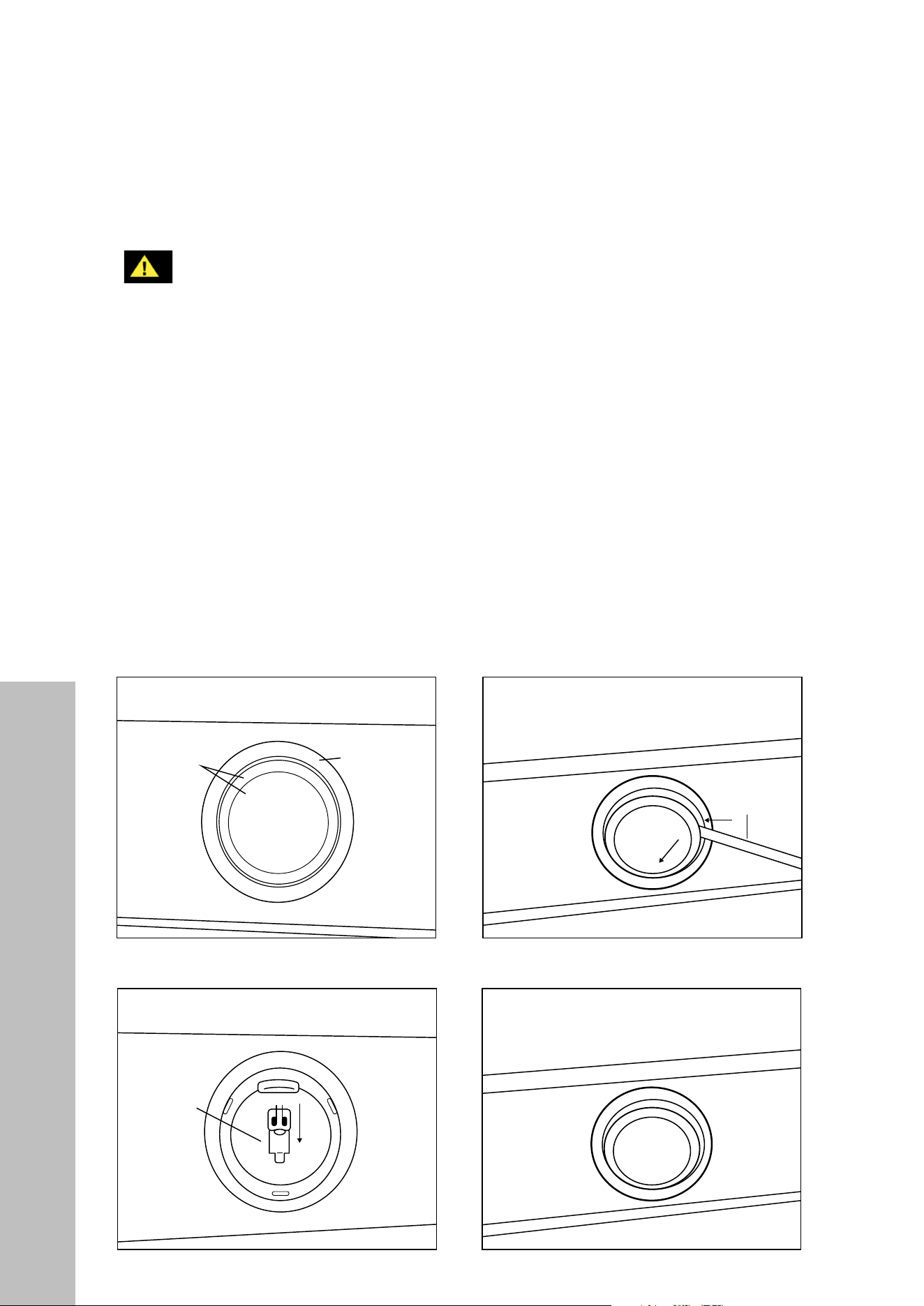
REPLACING LIGHT BULBS
WARNING
Never replace light bulbs while the power is on. Always unplug the unit or switch
the electrical breaker to the off position. This range hood uses 20-watt, 12-volt
halogen bulbs. Do not handle halogen bulbs with bare fingers, as this will leave
oily residue on bulbs and may shorten the life of the bulb.
• Remove the baffle filters, then reach in the hood and feel for the back of lights’ prongs.
• Press the two prongs and gently push forward on the light for it to come out.
• Wear a cotton glove or use a cloth to handle replacement bulbs. NOTE: DO NOT push
the bulb in too hard, as the light’s “legs” may break off.
• Once the light is replaced, turn on breaker and range hood to test for operation.
• Alternatively, remove lights from the front of the unit by using the screwdriver method
outlined in the figures below. NOTE: This method is not recommended due to the potential
to damage the hood and lighting housing, which may void your warranty.
4
Under Cabinet
Range Hood
Cabinet or Single-Piece
Chimney (Optional)
Countertop/Stove
Halogen light
glass cover
1
Halogen light
housing
Flat headed
screwdriver
Halogen light
bulb 12V 20W
2 3
36"
Counter
Top
Ceiling
Height
Min: 30"
Max: 36"
Range
Hood
Height
Cabinet
Height
4
Under Cabinet
Range Hood
Cabinet or Single-Piece
Chimney (Optional)
Countertop/Stove
Halogen light
glass cover
1
Halogen light
housing
Flat headed
screwdriver
Halogen light
bulb 12V 20W
2
3
36"
Counter
Top
Ceiling
Height
Min: 30"
Max: 36"
Range
Hood
Height
Cabinet
Height
4
Under Cabinet
Range Hood
Cabinet or Single-Piece
Chimney (Optional)
Countertop/Stove
Halogen light
glass cover
1
Halogen light
housing
Flat headed
screwdriver
Halogen light
bulb 12V 20W
2
3
36"
Counter
Top
Ceiling
Height
Min: 30"
Max: 36"
Range
Hood
Height
Cabinet
Height
4
Under Cabinet
Range Hood
Cabinet or Single-Piece
Chimney (Optional)
Countertop/Stove
Halogen light
glass cover
1
Halogen light
housing
Flat headed
screwdriver
Halogen light
bulb 12V 20W
2 3
36"
Counter
Top
Ceiling
Height
Min: 30"
Max: 36"
Range
Hood
Height
Cabinet
Height
23
Troubleshooting
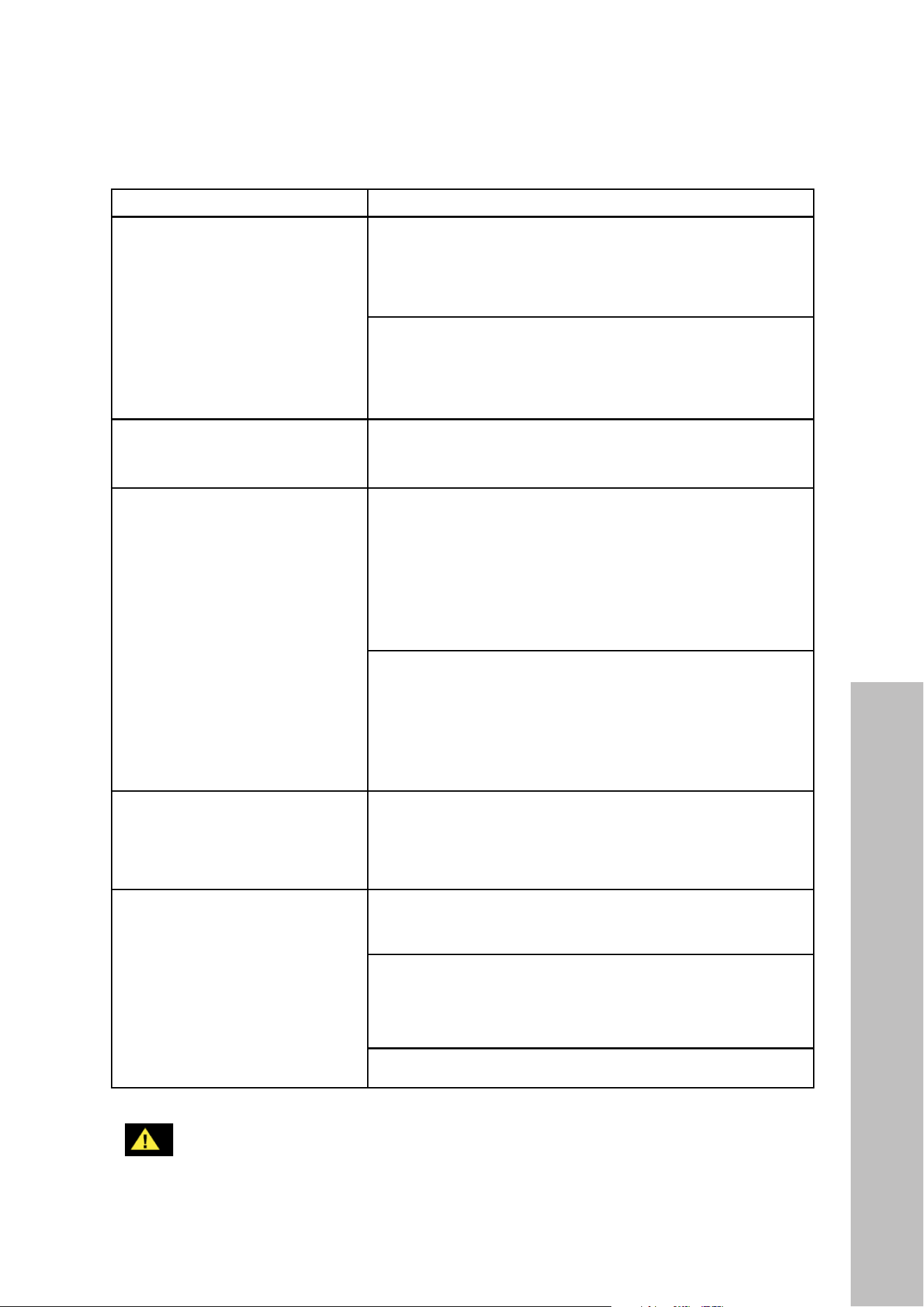
TROUBLESHOOTING
ISSUE SOLUTION
If the range hood or halogen
light does not operate after
installation.
Check if the range hood has been plugged in, make sure
that all power has been turned back on, fuses are not
blown and all electrical wiring is properly connected.
Swap out light assembly to working ones to determine
whether it is caused by defective bulbs. See
“Replacing Light Bulbs” on page 22.
The range hood vibrates when
the blower is on.
The hood might not have been secured properly to the
ceiling or wall. Re-check all screws and brackets.
The blower or
fan seems weak.
Check that the duct sized used is at least 7" (178 mm) or
3 1/4 x 10" (254 mm). Range hoods will not function
efficiently with insufficient duct size. For example: a
8" (203 mm) duct over a 7" (178 mm) hole that’s
loosely secured.
Check if ducting is clogged or if damper unit (half-circular
flapper) is not installed correctly or opening properly.
A tight mesh on a side wall cap unit might also cause
restriction to the air flow.
The lights work but the blower
is not spinning at all, is stuck
or is rattling.
The blower might be jammed or scraping the bottom due
to shipping damage. Contact ZLINE Customer Service.
The hood is not venting
out properly.
Make sure the distance between the stove top and hood
bottom is within 30" and 36" (762 mm and 914 mm).
Reduce the number of elbows and length of duct work.
Check if all joints are properly connected, sealed, and
taped. Use a maximum of 40' (12192 mm) of ductwork
Make sure the power is on high speed for heavy cooking.
WARNING
If a problem cannot be resolved after following the instructions in this manual,
please contact ZLINE Customer Service at 1-614-777-5004. Never attempt
to repair or disassemble a faulty range hood. Always consult a professional.

COVERAGE
ZLINE Kitchen and Bath (“ZLINE”) range hood parts will be warrantied for three years from
the original date of product delivery for the original purchaser of the product.
ZLINE warranty periods begin from the original date of product delivery and solely cover the
original purchaser of the product, delivered new and in its original carton. ZLINE will provide
free-of-charge, non-consumable replacement parts for the components that failed due to
manufacturing defects.
Additionally, range hoods purchased on or after January 2017 carry a lifetime warranty on
the motor. It is the responsibility of the customer to install all replacement parts and motors, as
ZLINE does not perform service repairs on its range hood products.
ZLINE’s liability is limited to the original purchase price of the product. Additional injuries,
losses, damages, or other inconveniences caused by product malfunction or defects in
materials are not covered under the terms of this warranty.
TERMS
ZLINE warranties apply only to the original purchaser of a ZLINE product installed for normal
residential use. This is defined as a single-family, residential dwelling in a non-commercial
setting. Any warranty claim stemming from installation, operation, or any other use within a
commercial setting is not covered under this limited warranty. Commercial settings include,
but are not limited to: schools, churches, hotels, restaurants, vacation rentals such as Airbnb,
daycare centers, private clubs, fire stations, common areas in multi-family dwellings, nursing
homes, food service locations, and institutional food service locations such as hospitals or
correctional facilities.
This warranty is non-transferable and will not under any circumstance be extended based
on the date of installation — the warranty period takes effect from the date of delivery and
only covers the original purchaser. The warranty applies only to products installed in the
contiguous United States and the District of Columbia.
WARRANTY

Out-of-pocket payments will not be reimbursed for replacement parts unless prior approval is
received from ZLINE. Unapproved out-of-pocket payments for parts will not be reimbursed.
Out-of-pockets for any type of service will not be reimbursed, as ZLINE does not perform
service repairs on its range hood products. All warranty procedures must be followed to
maintain warranty coverage.
If ZLINE is unable to replace the defective part after a reasonable number of attempts,
ZLINE reserves the right to offer to replace the product or provide the original purchaser a
full refund of the purchase price of the product (not including installation, removal, or other
charges that were not included in the original purchase price).
The original purchaser of the product must provide the original proof of purchase, including
the purchase date, when filing a claim to obtain replacement parts or refunds. Additionally,
the original purchaser of the product must provide the serial number of the product when
filing a claim to obtain replacement parts or refunds.
This warranty shall not apply to any ZLINE product in which the original factory serial
number has been removed, altered, or cannot be readily determined for any reason. Further,
ZLINE is not responsible for damage resulting from, but not limited to: shipment, delivery, or
improper installation; negligence or improper maintenance, misuse, or abuse of the product;
unauthorized alteration, modification, or tampering with the product; accident, fire, floods,
pest infestations, pandemics, natural disasters, or any other unpreventable or unexplained
acts of nature, commonly referred to as “acts of God”; flare-up fires or damages caused
by improper electric supply, electrical line current, voltage, or power surges; and service
to correct installation not in accordance with the instructions contained in ZLINE’s product
manuals and/or with local government codes.
Additionally, this range hood warranty does not apply to aesthetic damage, scratches,
or natural wear caused by normal use; second-hand, open box products, or products
purchased from an unauthorized retailer; consumable parts including, but not limited to,
metal and charcoal filters; and damages, problems, or any type of performance-related
issues stemming from alteration or tampering with the range hood, including, but not limited
to, painting stainless steel, black stainless, DuraSnow
®
, or designer- or wood-finished range
hoods, and manipulating the electrical wiring beyond what is described in this manual.
WARRANTY

Information contained within ZLINE’s installation and user manuals, in addition to product
information included on ZLINE’s website and all related digital listings, do not cover every
possible condition and situation that may occur during the installation or operation of
ZLINE products.
ZLINE reserves the right to make changes at any time to its products when considered safe,
necessary, and useful. Always check the ZLINE website for the most up-to-date version of its
product manuals: www.zlinekitchen.com/pages/manuals.
Do not install or operate any ZLINE product if it has missing or broken parts or if it arrives
damaged due to shipping. If ZLINE products arrive damaged, contact ZLINE Customer
Experience at 1-614-777-5004 for help. Failure to report a damaged appliance prior to
installation or operation may void the warranty. ZLINE does not perform service repairs on
its range hood products.
ZLINE disclaims responsibility for damage or injury caused by improper installation or
use of any of its products. ZLINE is under no obligation, by law or otherwise, to provide
concessions, including repairs, prorates, rebates, discounts, or replacements, once the
warranty has expired.
SERIAL NUMBER LOCATION
The rating tag shows the model and serial number of your
range hood. Please write down the model number and
serial number of your appliance. The serial number is
located behind the baffle filters near the motor. Both are
needed to obtain warranty service. Do not remove
permanently affixed labels, warnings, or plates from
the product. This will void the warranty. You may also
consider attaching your receipt or proof of purchase to
this manual.
WARRANTY

CUSTOMER SERVICE AND PARTS INFORMATION
Please contact ZLINE Customer Service for questions and
troubleshooting help at 1-614-777-5004 or visit
www.zlinekitchen.com/contact to utilize our online Customer
Experience Portal.
Scan the QR code to view the most up-to-date version of ZLINE’s
range hood Installation and User Manuals.
Need to purchase a part or accessory for your ZLINE product? Visit
www.zlineparts.com, ZLINE’s official parts distribution partner.
WARRANTY