
Public
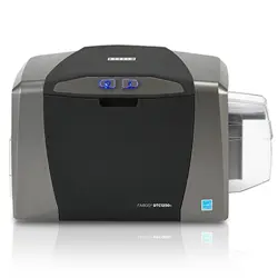
HID® FARGO®
DTC™1250e,
DTC1000Me,
DTC4250e,
and
DTCii
Plus
Card Printer
User Guide
PLT-01668,
1.X
Powering
Trusted Identities
HID®
FARGO®
DTC™1250e,
DTC1000Me,
DTC4250e,
and
DTCii
Plus
Card
Printer
User
Guide
PLT-01668,
1.X
2
July
2025
Public
Copyright
© 2016 - 2025 HID Global Corporation/ASSA ABLOY AB. All rights reserved.
This document may not be reproduced, disseminated, or republished in any form without the prior written permission of
HID Global Corporation.
Trademarks
HID GLOBAL, HID, the HID Brick logo, Asure ID, DTC, FARGO, FARGO WorkBench, iCLASS, Prox, Proximity, SIO, and
UltraCard are trademarks or registered trademarks of HID Global, ASSA ABLOY AB, or its affiliate(s) in the US and other
countries and may not be used without permission. All other trademarks, service marks, and product or service names
are trademarks or registered trademarks of their respective owners.
MIFARE, MIFARE Classic, MIFARE DESFire, MIFARE DESFire EV1, MIFARE Plus, and MIFARE Ultralight are registered
trademarks of NXP B.V. and are used under license.
Contacts
For technical support, please visit: https://support.hidglobal.com.
What's
new
Date
Description
Revision
July
2025
Updated
technical
specifications.
1.7
A complete list of revisions is available in Revision history.

Powering
Trusted Identities
HID®
FARGO®
DTC™1250e,
DTC1000Me,
DTC4250e,
and
DTCii
Plus
Card
Printer
User
Guide
PLT-01668,
1.X
3
July
2025
Public
Specifications ____________________________________________________________________________
5
1.1
Introduction __________________________________________________________________________________________ 6
1.2
Regulatory compliance ________________________________________________________________________________ 6
1.2.1
Agency listings __________________________________________________________________________________ 6
1.2.2
United States ___________________________________________________________________________________ 7
1.2.3
Canada ________________________________________________________________________________________ 7
1.2.4
Taiwan _________________________________________________________________________________________ 7
1.2.5
Japan __________________________________________________________________________________________ 7
1.2.6
Korea __________________________________________________________________________________________ 7
1.3
Safety messages _____________________________________________________________________________________ 8
1.3.1
Safety messages - United States ___________________________________________________________________ 8
1.3.2
Safety messages - French ________________________________________________________________________ 9
1.3.3
Safety messages - Taiwan _______________________________________________________________________ 10
1.3.4
Safety messages - China ________________________________________________________________________ 11
1.4
Technical specifications ______________________________________________________________________________ 12
1.5
Functional specifications _____________________________________________________________________________ 14
1.6
Printer components: print ribbons _____________________________________________________________________ 15
1.6.1
Ribbon types and print counts ____________________________________________________________________ 15
1.7
Printer components: blank cards ______________________________________________________________________ 16
Setup
and
installation
procedures
_____________________________________________________________
17
2.1
Introduction _________________________________________________________________________________________ 18
2.2
Choosing a good location _____________________________________________________________________________ 18
2.2.1
About moisture condensation ____________________________________________________________________ 18
2.3
Unpacking and inspection ____________________________________________________________________________ 18
2.4
Installing the print ribbon cartridge _____________________________________________________________________ 19
2.4.1
Installing the ribbon _____________________________________________________________________________ 19
2.5
Installing blank cards into the input card hopper _________________________________________________________ 20
2.5.1
For DTC1250e, DTC1000Me, and DTC4250e models ________________________________________________ 20
2.5.2
For DTCii Plus or DTC4250e models with Dual Input Card Hopper ____________________________________ 22
2.5.3
Exception feeding from the LCD (DTCii Plus only) ___________________________________________________ 23
2.6
Installing the output hopper for the DTCii Plus __________________________________________________________ 24
2.7
Card size selection __________________________________________________________________________________ 24
2.8
Connecting the printer power _________________________________________________________________________ 27
Print
driver
installation
______________________________________________________________________
28
3.1
Introduction _________________________________________________________________________________________ 29
3.2
Driver installation instructions _________________________________________________________________________ 29
Printer
preferences
________________________________________________________________________
30
4.1
Introduction _________________________________________________________________________________________ 31

Powering
Trusted Identities
HID®
FARGO®
DTC™1250e,
DTC1000Me,
DTC4250e,
and
DTCii
Plus
Card
Printer
User
Guide
PLT-01668,
1.X
4
July
2025
Public
4.2
Card tab ___________________________________________________________________________________________ 31
4.2.1
Toolbox window ________________________________________________________________________________ 32
4.3
Device Options tab __________________________________________________________________________________ 45
4.3.1
Fluorescent panels _____________________________________________________________________________ 46
4.4
Configuring fluorescent data using the application _______________________________________________________ 48
4.4.1
Creating fluorescent text ________________________________________________________________________ 48
4.4.2
Creating a fluorescent image _____________________________________________________________________ 48
4.5
Image Color tab _____________________________________________________________________________________ 50
4.5.1
Advanced Settings______________________________________________________________________________ 51
4.6
Image Calibrate tab __________________________________________________________________________________ 53
4.7
Magnetic Encoding tab ______________________________________________________________________________ 54
4.7.1
Magnetic Track Options _________________________________________________________________________ 56
4.8
Overlay / Print Area tab _____________________________________________________________________________
59
4.8.1
Defining an overlay or print area __________________________________________________________________ 60
4.9
K Panel Resin tab ____________________________________________________________________________________ 63
4.9.1
Defined area ___________________________________________________________________________________ 64
4.10
Printer Info tab _____________________________________________________________________________________ 65
System
overview
-
troubleshooting
____________________________________________________________
66
5.1
Sequence of operations ______________________________________________________________________________ 67
5.2
Troubleshooting _____________________________________________________________________________________ 68
5.2.1
Printer Error buttons ____________________________________________________________________________ 68
5.2.2
Error messages ________________________________________________________________________________ 69
5.2.3
Troubleshooting with the Error Message table ______________________________________________________ 70
5.2.4
Printer-specific tools (DTC1250e, DTC4250e, and DTCii Plus) ________________________________________ 73
Firmware
upgrades
________________________________________________________________________
75
6.1
Upgrade information _________________________________________________________________________________ 76
Technical
support
_________________________________________________________________________
77
7.1
Introduction _________________________________________________________________________________________ 78
7.2
Reading the serial numbers on a FARGO printer _________________________________________________________ 78
DTCii
Plus ______________________________________________________________________________
79
A.1
Introduction ________________________________________________________________________________________ 80
A.2
Locking system _____________________________________________________________________________________ 80
A.3
Accessory procedures: using the security lock slot _______________________________________________________ 80

Public
Section 01
Specifications
Public
1.1
Introduction
The purpose of this section is to provide you with specific information on the Regulatory Compliances, Agency Listings,
Technical Specifications and Functional Specifications for the DTC™1250e, DTC1000Me, DTC4250e, and DTCii Plus
card printers.
1.2
Regulatory
compliance
Agency
Regulatory
compliance
UL
The card printer is listed under UL 62368-1, 3
rd
Ed, 2021-10-22 (Audio/video, information and communication
technology equipment Part 1: Safety requirements) File Number:
E145118
Note: This product is intended to be supplied by a Listed Power Unit marked Class 2 and rated for 24 Vdc,
3.3 A minimum.
CSA
The printer manufacturer has been authorized by UL to represent the card printer as CSA certified under CSA
Standard C22.2 No. 62368-1-19, 3
rd
Ed, 2021-10-22 (Audio/video, information and communication
technology equipment Part 1: Safety requirements) File Number:
E145118
FCC
The card printer complies with the requirements in Part 15 of the FCC rules for a Class A digital device.
DTC1250e FCC ID: JQ6-DTC1250E
DTC1000Me FCC ID: JQ6-X001800DTC
DTC4250e FCC ID: JQ6-X001800DTC
DTCii Plus FCC ID: JQ6-DTCIIPLUS
CE
The card printer has been tested and complies with EN300-330-1, EN300-330-2, EN301-489-1, EN301-489-3,
EN55032 class A, EN55035, EN61000-3-2, EN61000-3-3, EN62368-1.
Note: Based on the above testing, the printer manufacturer certifies that the card printer complies
with the following European Council Directives and has placed the CE mark on the card
printer.
Environmental
RoHS2, REACH, Power Supply Efficiency Level VI
Additional Agency Listings
BIS, WPC, MIC, NCC, KCC, RCM
Public
Note:
This equipment has been tested and found to comply with the limits for a Class A digital device, pursuant to
part 15 of the FCC Rules. These limits are designed to provide reasonable protection against harmful
interference when the equipment is operated in a commercial environment. This equipment generates, uses,
and can radiate radio frequency energy and, if not installed and used in accordance with the instruction
manual, may cause harmful interference to radio communications. Operation of this equipment in a
residential area is likely to cause harmful interference; in which case, you are required to correct the
interference at your expense.
1.2.1
United
States
This device complies with Part 15 of the FCC rules. Operation is subject to the following two conditions:
1.
This device may not cause harmful interference.
2.
This device must accept any interference received, including interference that may cause undesired operation.
The radiated output power of this device meets the limits of FCC radio frequency exposure limits. This device should be
operated with a minimum separation distance of 20cm (8inches) between the equipment and a person’s body.
1.2.2
Canada
This device complies with ISED license-exempt RSS standard(s). Operation is subject to the following two conditions: (1) this
device may not cause interference, and (2) this device must accept any interference, including interference that may cause
undesired operation of the device.
Le présent appareil est conforme aux CNR d'ISED applicables aux appareils radio exempts de licence. L'exploitation est
autorisée aux deux conditions suivantes: (1) l'appareil ne doit pas produire de brouillage, et (2) l'utilisateur de l'appareil doit
accepter tout brouillage radioélectrique subi, même si le brouillage est susceptible d'en compromettre le fonctionnement.
This equipment complies with ISED radiation exposure limits. This equipment should be installed and operated with minimum
distance 20cm between the radiator and your body.
Cet équipement est conforme aux limites d'exposition aux rayonnements d'ISED. Il doit être installé et utilisé à une distance
minimale de 20 cm du corps.
1.2.3
Taiwan
經型式認證合格之低功率射頻電機,非經許可,公司、商號或使用者均不得擅自變 更頻率、加大功率或變更原設計
之特性及功能。低功率射頻電機之使用不得影響飛航安全及干擾合法通信;經發現有干擾現象時,應立即停用,並改
善至無干擾時方得繼續使用。前項合法通信,指依電信法規定作業之無線電通信。低功率射頻電機須忍受合法通信
或工業、科學及醫療用電波輻射性電機設備之干擾。
1.2.4
Japan
この装置は総務省の型式指定を受けています。" ( 総務省指定番号は第 AC-XXXXX 号で
す)本製品は電波を使用したRFID 機器の読み取り・書き込み装置です。
そのため使用する用途・場所によっては、医療機器に影響を与える恐れがあります
1.2.5
Korea
이 기기는 업무용 (A 급 ) 전자파 적합기기로서 판매자 또는 사용자는 이 점을 주의하시길 바라며 , 가정 외의 지역
에서 사용하는 것을 목적으로 합니다 .
Public
1.3
Safety
messages
1.3.1
Safety
messages
-
United
States
Symbol
Critical
Instructions
for
Safety
Purposes
Danger
Failure
to
follow
these
guidelines
results
in
personal
injury
or
death.
To
prevent
personal
injury
or
death:
Reference
the
following
safety
messages
before
performing
an
operation.
Always remove the power cord prior to performing repair procedures, unless otherwise specified.
Ensure only qualified personnel perform these procedures.
ESD
This device is electro statically sensitive. You may damage the device if exposing it to static electricity discharges.
To prevent damage:
Reference
the
following
safety
messages
before
performing
an
operation.
Observe all established Electrostatic Discharge (ESD) procedures while handling cables in or near the circuit board and
print head assemblies.
Always
wear
an
appropriate
personal
grounding
device.
Always remove the ribbon and cards from the printer before making any repairs, unless otherwise specified.
Remove jewelry and thoroughly clean hands before working on the printer.
Caution
This symbol warns of an electrical hazard that could result in personal injury or death.
Caution
For safety purposes, do not use Ethernet for a direct connection outside of the building.
Public
1.3.2
Safety
messages
-
French
Symbole
Instructions
critiques
visant
la
Sécurité
Danger
Si ces directives ne sont pas suivies les résultats peuvent être des lésions corporelles ou la mort. Pour éviter des lésions
corporelles ou la mort:
Rapportez-vous aux
avis
suivants
de
sécurité
avant
de procéder
à une
opération.
Retirez
toujours
le
câble
d’alimentation
avant
d’effectuer
des
procédures
de
réparation,
sauf
spécification
contraire.
Assurez-vous
qu’uniquement
des
personnes
qualifiées
réalisent
des
procédures.
ESD
Ce dispositif est sensible à l’électricité statique. Il peut souffrir des dommages s’il est exposé à des décharges
électrostatiques.
Pour éviter des dommages:
Rapportez-vous
aux
messages
suivants
avant
de
procéder
à
une
opération.
Suivez toutes les procédures de Décharges Electrostatiques (ESD) en vigueur durant le maniement des câbles dans ou à
proximité des Ensembles de Cartes de Circuit Imprimé et Tête d’Impression.
Portez toujours un dispositif de mise à la terre personnelle appropriée.
Retirez
toujours
le
ruban
et
les
Cartes
de
l’Imprimante
avant
d’effectuer
toute
réparation,
sauf
spécification
contraire.
Retirez tous bijoux et lavez soigneusement vos mains avant de travailler à l’Imprimante.
Attention
Ce symbole est un avis de péril électrique passible de résulter en lésion corporelle ou mort.
Attention
Pour des motifs de sécurité, n’utilisez pas Ethernet pour une connexion directe hors du bâtiment.
Public
1.3.3
Safety
messages
-
Taiwan
繁體中文 射頻發射及安全指令 安全訊息 ( 小心檢查 )
標記
重要的安全事項說明
危險
未按照說明安裝可能造成人員傷亡。
在可能產生潛在安全問題的地方有警示標記。
( 如左圖所示) 。
為了避免人員傷害,在進行有此警示標記的操作前 ,請先參考安全資訊提示。
為了避免人員傷害,在沒有特別說明的情況下,修理前請關掉電源開關。
小心
此設備對靜電很敏感。如果受到靜電放電,設備會損壞。在可能產生潛在靜電安全問題的地方有警示標
記。
( 如左圖所示) 。
為了避免損壞設備,在進行有此警示標記的操作前 ,請先參考安全資訊提示。
為了避免損壞設備,在排放電路板和印刷頭聯合裝置裡面或附近的電線時 ,請注意觀察所有的靜電
放電設備。
為了避免損壞設備,請隨時佩戴合適的接地裝置 ( 比如:手腕上戴一個高品質的接地手腕帶以免受
到可能的傷害) 。
為了避免損壞設備,如果沒有特殊說明,在做任何修理前,請取下印表機上的色帶和卡。
為了避免損壞設備,在使用印表機之前,請摘下戒指和手上飾品,並仔細清洗手上的油脂。
警告使用者:
這是甲類的資訊產品,在居住的環境中使用時,可能會造成射頻干擾,在這種情況下,使用者會被要求
採取某些適當的對策措施
Public
1.3.4
Safety
messages
-
China
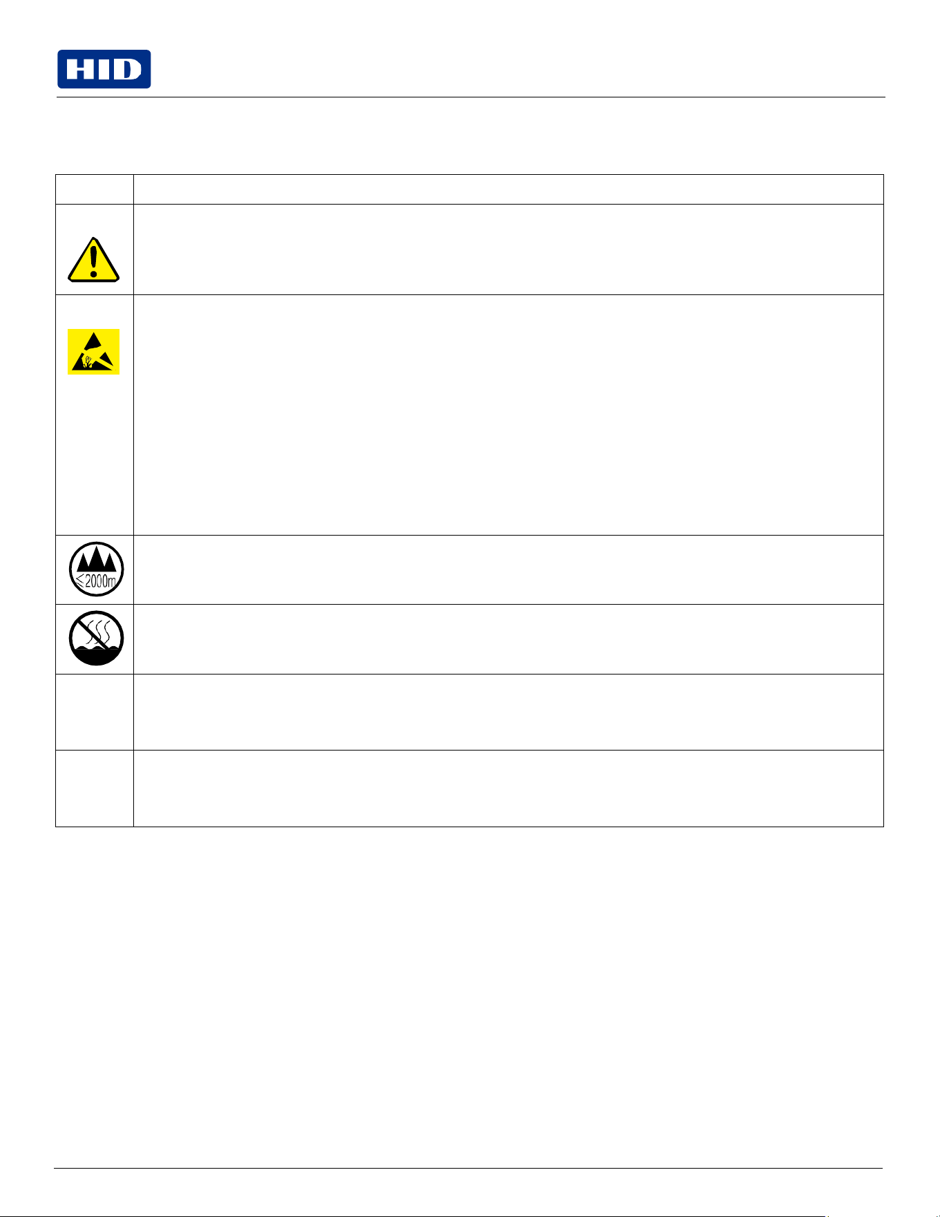
安全消息( 请仔细阅读 )
符号
涉及安全的重要过程
危险
如果不遵循这些安装指南进行操作 ,可能会导致重伤,甚至死亡。可能引发安全问题的信息由警告符
号( 如左图所示) 来表示。
为了确保人身安全,在执行前面带有此符号的操作之前 ,请先阅读下面的安全消息。
为了确保人身安全,除非另有规定,否则在执行维修过程 前,始终应断开电源。
小心
此设备为静电敏感设备。如果暴露在静电电流下,可能会损坏设备。可能引发静电安全问题的信息由警
告符号( 如左图所示) 来表示。
?了防止 设备或介质受损 ,在执行前面带有此符号的操作之前 ,请先阅读下面的安全消息。
为了防止设备或介质受损,请在处理电路板和打印头部件中或附近的 电缆时 ,遵守所有规定的静电
放电 (ESD)过程。
为了防止设备或介质受损,请始终佩带适当的个人接地设备 ( 例如,已接地避免出现潜在损坏的高
质量腕带) 。
为了防止设备或介质受损,除非另有规定 ,否则在执行任何维修过程前,始终应将色带和证卡与打
印机分离。
为了防止设备或介质受损,在操作打印机前,请取下手指和手上的珠宝饰物 ,并将手上的油渍和污
渍彻底清洗干净。
仅适用于海拔2000m 以下地区安全使用
Use only at altitudes not
more than 2000m
above
sea
level.
仅适用于非热带气候条件下安全使用
环境保护(中国-RoHS)
环保使用期是基于本产品用于办公环境。
Environmental Protection Use
Period is based on the product being used in an office environment.
警告:
此为A级产品,在生活环境中,该产品可能会造成无线电干扰。在这种情况下,可能需要用户对其干扰采
取可行的措施。
Public
1.4
Technical
specifications
Term
Function
Print
Method
Dye Sublimation / Resin Thermal Transfer
Print
resolution
300 dpi
(11.8
dots/mm);
continuous
tone
Colors
Up to 16.7 million colors / 256 shades per pixel
Print Ribbon Options
Full-color with resin black and overlay panel, YMCKO* (250 prints)
Full-color half-panel with resin black and overlay panel, YMCKO* (350 prints)
Full-color with two resin black panels and overlay panel, YMCKOK* (200 prints)
Full-color with fluorescing, resin black panel and overlay panel, YMCFKO* (200 prints) Full-color with
fluorescing, two resin black panels and overlay panel, YMCFKOK* (400 prints)
Full-color half-panel with two resin black and overlay panel, YMCKOK* (500 prints)
Full-color half-panel with two resin black and two overlay panels, YMCKOK* (500 prints) Resin black and
overlay panel, KO* (1250 prints)
Dye-sublimation black and overlay print, BO* (1250 prints) Resin black (standard and premium) (1000 prints)
Resin green, blue, red, white (1000 prints) Resin silver (2000 prints)
Resin
gold
(1000
prints)
Rewrite
technology
–
No
ribbon
is
required
* Indicates the ribbon type and the number of ribbon panels printed where Y=Yellow, M=Magenta, C=Cyan,
K=Resin Black, O=Overlay, F=Fluorescing Resin
Print
Speed
6
seconds
per
card
(K*)
8
seconds
per
card
(KO*)
16 seconds per card (YMCKO*) 24 seconds per card (YMCKOK*)
Print speed indicates an approximate batch print speed and is measured from the time a card feeds into the
printer to the time it ejects from the printer.
Print speeds do not include encoding time or the time needed for the PC to process the image.
Process time is dependent on the size of the file, the CPU, amount of RAM and the amount of available
resources at the time of the print.
* Indicates the ribbon type and the number of ribbon panels printed where Y=Yellow, M=Magenta, C=Cyan,
K=Resin Black, O=Overlay, F=Fluorescing Resin
Card Size and Types
Supported
CR-80: 85.6 mm × 54 mm (3.375″ × 2.125″)
CR-79: 84.1 mm × 52.4 mm (3.313″ × 2.063″)
Accepted Standard Card
Sizes
CR-80 edge-to-edge: 85.3 mm × 53.7 mm (3.36″ × 2.11″)
CR-79: 83.8 mm × 51.8 mm (3.3″ × 2.04″)
Accepted
Card
Thickness
0.229
mm
–
1.016
mm
(0.009″
-
0.040″
/
9
mil
–
40
mil)
Accepted
Card
Types
PVC or polyester cards with polished PVC finish; monochrome resin required for 100% polyester cards; optical
memory cards with PVC finish; rewrite.
Input Hopper Card
Capacity
100
cards:
0.762.mm
(0.030″)
DTC1250e,
DTC1000Me,
DTC4250e
200
cards:
0.762
mm
(0.030″)
DTC4250e
with
Dual
Hopper,
DTCii
Plus
Output Hopper Card
Capacity
100 cards 0.762 mm (0.030″) DTC4250e, DTCii Plus
30 cards 0.762 mm (0.030″) DTC1250e
Public
Term
Function
Reject Hopper Card
Capacity
DTCii
Plus:
100
cards
0.762
mm
(0.030″)
DTC4250e:
100
cards
0.762
mm
(0.030″)
–
same-side
input/output
card
hopper
Card
Cleaning
Card
cleaning
roller
integrated
into
the
ribbon
cartridge.
A new cleaning roller is included with each ribbon cartridge.
Printer
Memory
32MB RAM
Operating
Systems
Windows
Server
2003
Windows
Server
2008
Windows
Server
2016
Windows
Server
2019
Windows
7
(32-
and
64-bit)
Windows
10
(32-
and
64-bit)
Interface
USB
2.0
and
Ethernet
with
internal
print
server
Operating
Temperature
18°C to 27°C (65°F to 80°F)
Humidity
20-80%
non-condensing
Dimensions
(H × W × D)
DTC1250e:
Single-sided printer: 224 mm × 348 mm × 201 mm (8.8″ × 13.7″ × 7.9″) (DTC1000Me)
Dual-sided printer: 249 mm × 475 mm × 234 mm (9.8″ × 18.7″ × 9.2″)
DTC4250e:
Single-sided printer: 249 mm × 460 mm × 234 mm (9.8″ × 18.1″ × 9.2″)
Dual-sided printer: 249 mm × 475 mm × 234 mm (9.8″ × 18.7″ × 9.2″)
DTCii Plus with output bin: 249 mm × 583 mm × 234 mm (9.8″ × 22.9″ × 9.2″)
Weight
Single-sided
printer:
3.63
kg
(8
lbs.)
Dual-sided
printer:
4.54
kg
(10
lbs.)
DTCii Plus: 5 kg (11 lbs.)
Agency
Listings
Safety: UL 60950-1, CSA C22.2 (60950-1), and CE; EMC; FCC Class A, CRC c1374, CE (EN 55022 Class A, EN
55024), CCC, BSMI, KCC
Supply
Voltage
100-240
VAC,
1.6
A
Supply
Frequency
50 Hz / 60 Hz
Warranty
Printer –
Two
years; Print
head
– Two
years,
unlimited
pass
with UltraCard™
Encoding Options
Supported
125
kHz
(HID
Prox)
reader
13.56
MHz
(iCLASS®,
MIFARE,
ISO
14443
A/B,
ISO
15693)
read/write
encoder
Contact Smart Card Encoder reads from and writes to all ISO7816 1/2/3/4 memory and microprocessor smart
cards (T=0, T=1) as well as synchronous cards
ISO Magnetic Stripe Encoding, dual high- and low-coercivity, Tracks 1, 2 and 3
Public
Term
Function
Options
Single wire Ethernet and USB 2.0 Interface for inline printing and encoding
Single wire Ethernet encoding is only available for iCLASS and Contact Smart Card encoding
Dual-Sided Printing Module – Upgradeable (DTC4250e ONLY)
Dual
Input
Card
Hopper
–
Upgradeable
(DTC4250e
ONLY)
Same-Side Input / Output Card Hopper – Upgradeable (DTC4250e ONLY)
Smart Card Encoding (contact/contactless) – Upgradeable (DTC4250e ONLY)
Magnetic Stripe Encoding – Upgradeable
Printer
Cleaning
Kit
Software
FARGO
Workbench™
Diagnosis
Utility
Display
Color changing status buttons (DTC1250e, DTC4250e)
Graphical Display (DTC4250e, DTCii Plus)
1.5 Functional
specifications
This card printer utilizes two different, yet closely related printing technologies to achieve its remarkable direct-to-card
print quality for dye-sublimation and resin thermal transfer.
Public
1.6 Printer
components:
print
ribbons
The card printer utilizes both dye-sublimation and/or resin thermal transfer methods to print images directly onto blank
cards. Since the dye-sublimation and the resin thermal transfer print methods each provide their own unique benefits,
print ribbons are available in resin-only, dye-sublimation-only and combination dye-sublimation/resin versions.
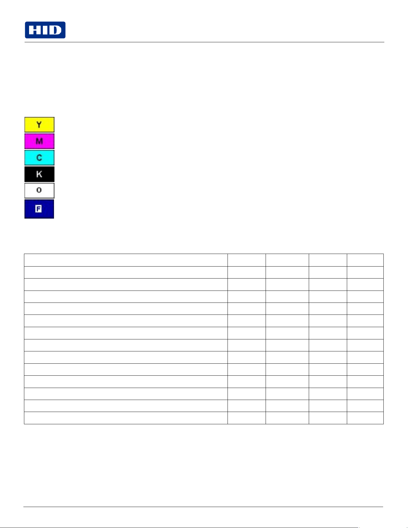
To make it easier to remember which print ribbons are which, a letter code has been developed to indicate the type of
ribbon panels found on each ribbon. This letter code is as follows:
Dye-Sublimation Yellow Panel
Dye-Sublimation Magenta Panel
Dye-Sublimation Cyan Panel
Resin Black Panel (Premium unless otherwise stated)
Clear Protective Overlay Panel
Fluorescing Panel
1.6.1
Ribbon types and print counts
The following table includes the ribbon types and typical print counts.
Ribbon
DTC1250e
DTC1000Me
DTC4250e
DTCii
Plus
YMCKO
–
Full
Color/Resin
Black
/
Overlay
250
N/A
250
N/A
YMCKO
Half
Panel
–
Full
Color
(1/2)
/
Resin
Black/Overlay
350
N/A
350
N/A
YMCFKO
-
Full
Color/UV
Fluorescing
/
Resin Black
/
Overlay
N/A
N/A
200
N/A
YMCKK
-
Full
Color
/
2
Resin
Black
N/A
N/A
N/A
N/A
YMCKOK - Full Color / 2 Resin Black / Overlay
200
N/A
200
200
YMCFKOK
-
Full
Color/UV
Fluorescing
/
2
Resin
Black
/
Overlay
N/A
N/A
N/A
N/A
YMCKOK
–
Half
Panel-Full
Color
(1/2)
/
2
Resin
Black
/
Overlay
N/A
N/A
N/A
N/A
YMCKOKO
–
Half
Panel-Full
Color
(1/2)
/
2
Resin
Black
/
2
Overlay
N/A
N/A
N/A
N/A
K – Standard Resin
1000
1000
1000
N/A
K – Premium Resin
1000
1000
1000
N/A
KO - Premium Black Resin / Overlay
500
500
500
250
SOK - Silver Metallic Resin / Overlay / Resin Black
N/A
N/A
N/A
350
None – Rewritable
Supported
Supported
Supported
Supported
Public
1.7
Printer components: blank cards
Type
Description
Card
Size
The
card
printer
accepts
standard
CR-79
and
CR-80
sized
cards.
Card
Surface
Suitable cards must have a polished PVC surface free of fingerprints, dust or any other types of embedded
contaminants. In addition, cards must have a completely smooth, level surface in order for the printer to
achieve consistent color coverage. Certain types of Proximity™ cards have an uneven surface that will inhibit
consistent color transfer.
Certain types of smart card chips are raised slightly above the cards surface which also results in poor color
transfer.
UltraCard Brand Cards
The UltraCard product line, available exclusively as part of HID Global FARGO brand secure card issuance
solutions, has a long standing reputation among dealers and end users for consistent quality in construction.
In addition to blank stock, the UltraCard line is available in a variety of configurations for magnetic stripe,
custom holograms and other additional anti-counterfeiting features.
UltraCard Premium is the preferred card for Direct-to-Card (DTC) applications that require a higher quality
card. The UltraCard Premium’s composite material construction provides for maximum durability,
flexibility and card life, with optimal resolution print quality for lamination and fluorescent panel ribbon
printing applications.
UltraCard PVC cards are medium-durability cards for a glossy, photo quality finish. These cards are
manufactured to ensure clean, scratch-free cards for high-quality prints and extended print head life.

Public
Section 02
Setup
and
installation
procedures

Public
Note: Allow for adequate clearance in front of the unit to accommodate the unit with its covers open.
2.1
Introduction
This section describes the setup and installation for the DTC1250e, DTC1000Me, DTC4250e, and the DTCii Plus card
printers.
2.2
Choosing a good location
The following guidelines help to ensure optimal printing performance:
Place the unit in a location with adequate air circulation to prevent internal heat buildup.
Use the printer's dimensions as a guideline for the minimum clearances to the unit.
Do not install unit near heat sources such as radiators or air ducts or in a place subject to direct sunlight, excessive
dust, mechanical vibration or shock.
2.2.1
About
moisture
condensation
If the unit is brought directly from a cold to a warm location or is placed in a very damp room, moisture may condense
inside the unit. Should this occur, print quality may not be optimal.
Leave the unit unplugged in a warm, dry room for several hours before using to evaporate any moisture.
Caution: For safety purposes, Ethernet is not intended for a direct connection outside of the building.
Attention: Pour des raisons de sécurité, Ethernet n'est pas conçu pour une connexion directe à l'extérieur du
bâtiment.
2.3
Unpacking
and
inspection
While unpacking your printer, inspect the carton to ensure that no damage has occurred during shipping. Make sure that
all supplied accessories are included with your unit.
Check that the following items are included:
Power supply
US/EU power cable
USB cable (2.0)
Card Printer User Guide
Warranty Statement, Compliance Document
Public
2.4
Installing the print ribbon cartridge
FARGO Direct-to-Card printers require highly specialized supplies to function properly.
The FARGO DTC1250e, DTC1000Me, DTC4250e, and DTCii Plus card printers use a one piece, disposable ribbon
cartridge system.
To maximize printer durability, reliability and printed card quality, only FARGO-certified supplies must be used. For this
reason, your FARGO warranty is void, where not prohibited by law, if you use non-FARGO-certified supplies.
Printer cleaning is recommended with each ribbon change to ensure quality printed cards.
Resin-only print ribbons consist of a continuous roll of a single resin color. No protective overlay panel (O) is provided
because resin images do not require the protection of an overlay.
2.4.1
Installing
the
ribbon
1.
Pull open front cover.
2.
Insert the print ribbon cartridge into the printer.
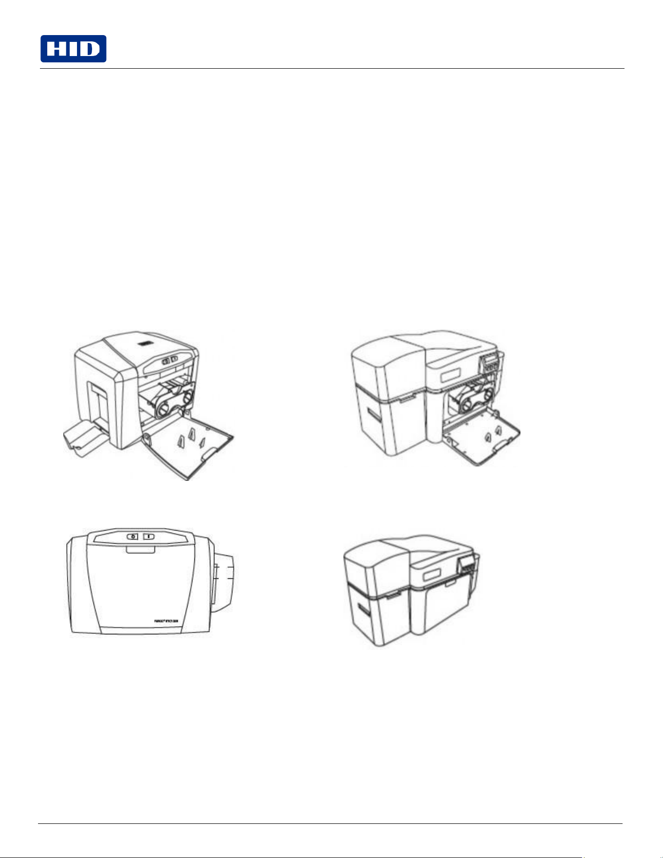
DTC1250e/DTC1000Me DTC4250e/DTCii Plus with Flipper Module
3.
Close the front cover.
DTC1250e/DTC1000Me DTC4250e with Flipper Module
Public
2.5
Installing
blank
cards
into
the
input
card
hopper
2.5.1
For
DTC1250e,
DTC1000Me,
and
DTC4250e
models
The FARGO DTC1250e, DTC1000Me, and DTC4250e card printers are capable of printing single feed cards and multiple
feed cards (batch mode). To print a single feed card, remove all cards from the input card hopper, leave its door closed
and place a card in the single feed card slot (which can be used repeatedly).
1.
Load the cards with the print side down and (if applicable) the magnetic strip up and towards the front of the printer.
Information: Do not run the cards with a contaminated, dull or uneven surface through the printer. Printing onto
these cards may lead to poor print quality and can greatly reduce the life of the print head.
Card types include PVC or PVC finish.
Cards eject into the output hopper or reject hopper.
Each input hopper holds 100 cards.
Certain types of smart card chips are raised slightly above the cards surface, which may result in poor color
transfer. Design the card with white space surrounding the chip.
2.
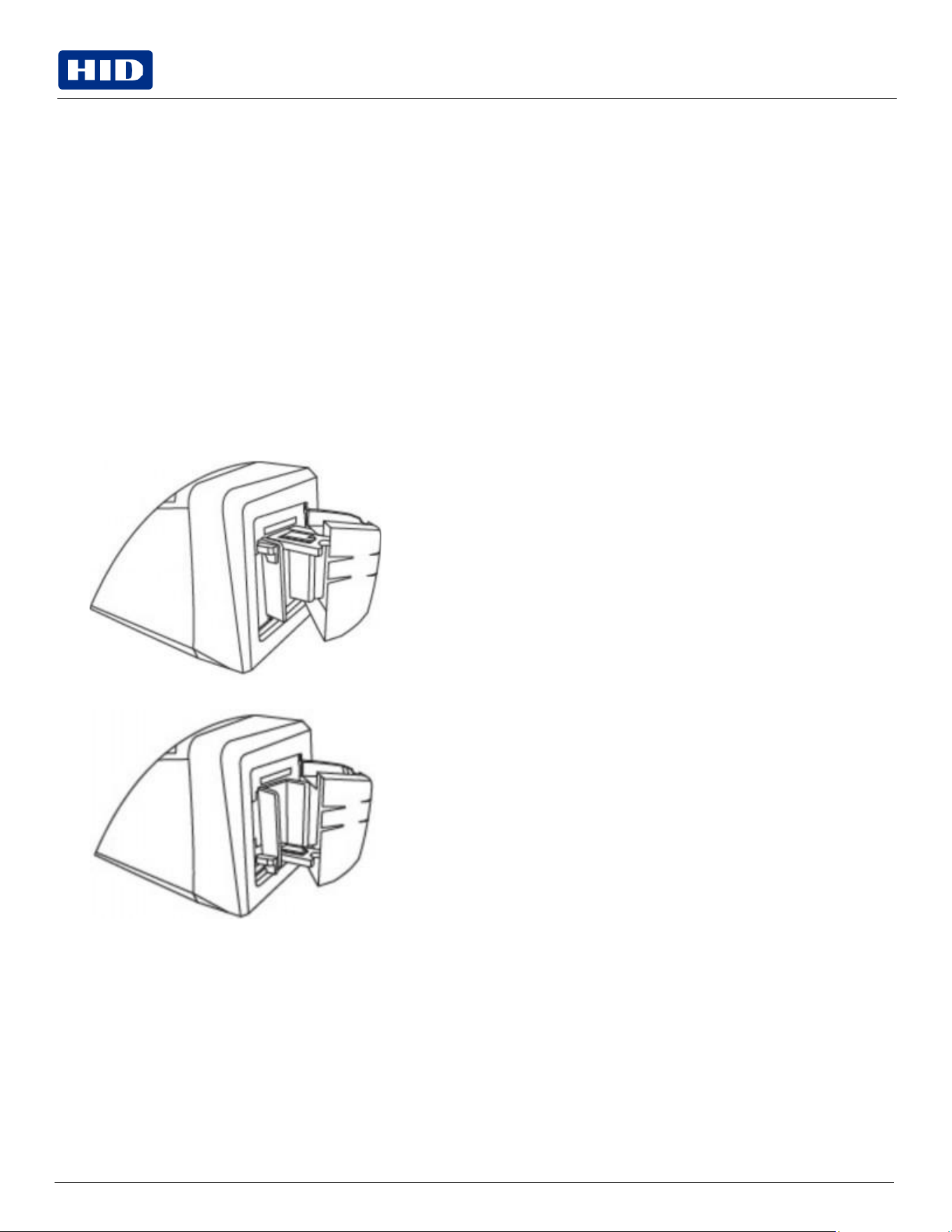
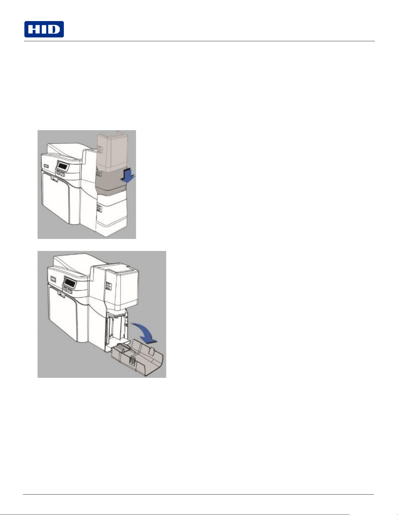
Open the input card hopper door.
3.
Press the card hopper load lever down until the card tray locks into place.
Public
4.
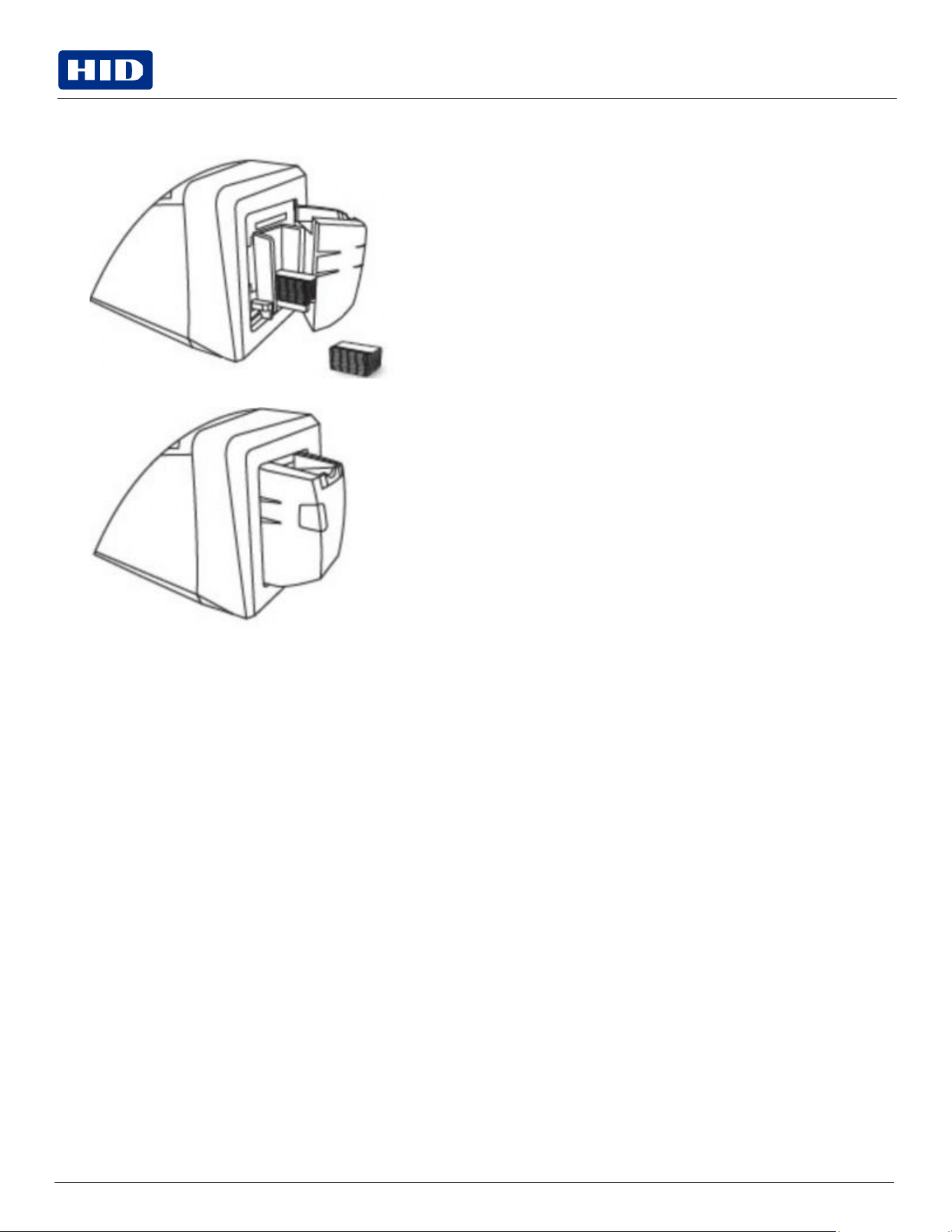
Load up to 100 cards into the hopper with the print side down. If using cards with a magnetic stripe, the magnetic
stripe should be loaded with the stripe up and to the front of the printer.
5.
Close the input card hopper door to release the lever to the printing position.
Public
2.5.2
For
DTCii
Plus
or
DTC4250e
models
with
Dual
Input
Card
Hopper
The FARGO DTCii Plus card printers or DTC4250e printers with dual input card hoppers are capable of printing different
types of cards located in the upper or lower tray of the dual input hopper for a total of 200 cards.
1.
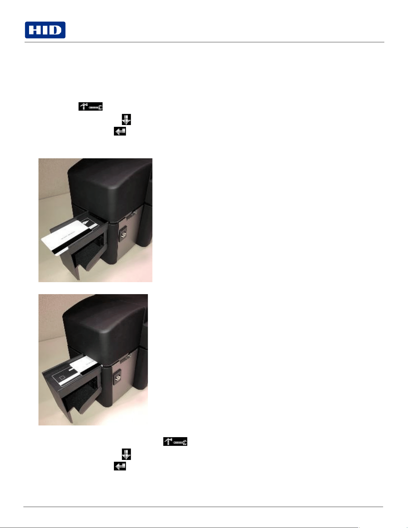
Slide up and open the dual input hopper upper door (Hopper 1).
2.
Load up to 100 cards into the upper hopper with the print side down.
If using cards with a magnetic stripe, the magnetic stripe should be loaded with the stripe up and to the front of the
printer.
3.
Close the dual input card hopper upper door to release the weight load onto the upper hopper cards.
4.
Open the input hopper lower door (Hopper 2).
5.
Press the card hopper load lever down until the card tray locks into place.
6.
Load up to 100 cards into the lower hopper with the print side down.
If using cards with a magnetic stripe, the magnetic stripe should be loaded with the stripe up and to the front of the
printer.
7.
Close the dual input hopper lower door to release the lever to the printing position.
Public
2.5.3
Exception
feeding
from
the
LCD
(DTCii
Plus
only)
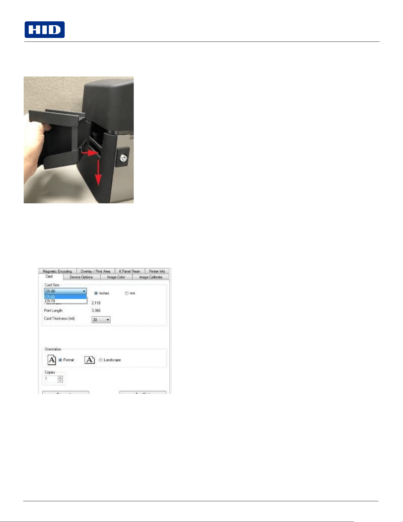
Use this option when you need to manually print a single card for a unique print job. This option must be enabled to
complete the unique print job. Once the print job is completed, the option must be disabled to resume printing from the
input card hopper.
1.
From the LCD on the printer, use the following steps to enable exception feeding:
a.
Press the button to scroll to Test Prints.
b.
Use the left down arrow to scroll to Hopper Select.
c.
Use the corner arrow
to
select
Exception
feeding.
2.
Send the unique print job to the printer.
3.
Place the card top-side down on the top of the output hopper.
4.
Slide the card into the printer until printer rollers accept the card.
5.
When the print job is completed, use the following steps to disable exception feeding:
a.
From the LCD on the printer, press the button to scroll to Test Prints.
b.
Use the left down arrow to scroll to Hopper Select.
c.
Use the corner arrow to enable the input card hopper.
Public
2.6
Installing the output hopper for the DTCii Plus
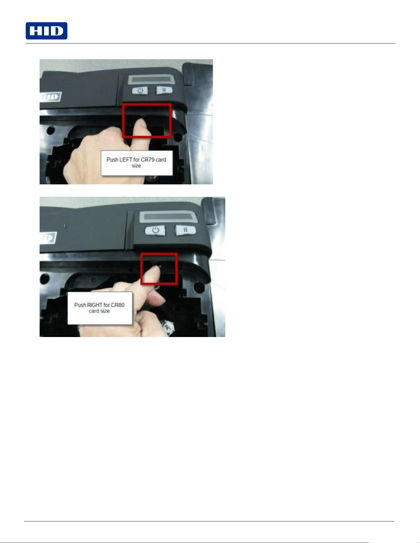
Place the card output hopper into the bottom slot on the left side of the printer, push down until it locks into place.
2.7
Card
size
selection
The printer uses standard size CR-70 and CR-80 cards.
Follow this procedure in the printer and in the printer driver to set up the card size.
1.
Open the front door and locate the slide bar.
Public
2.
If using the CR-79 card, push the slide bar to the LEFT.
3.
If using the CR-80 card, push the slide bar to the RIGHT.
Public
4.
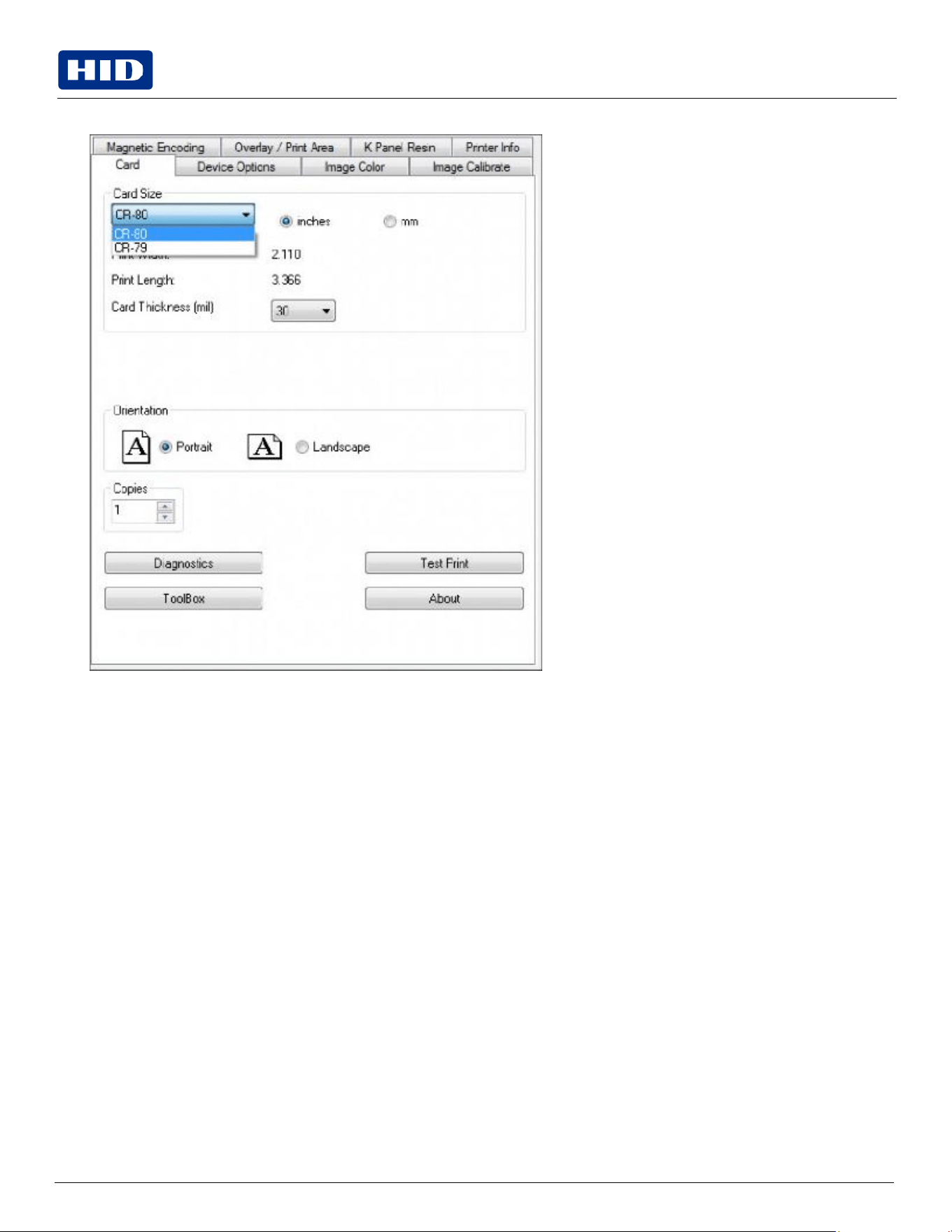
From the driver Printing Preferences, select the correct card size.
Public
Note: Do not connect the printer’s USB cable until prompted during the printer driver installation.
Note: The printer powers down during the "sleep time" but automatically powers up when a print job is sent.
2.8 Connecting
the
printer
power
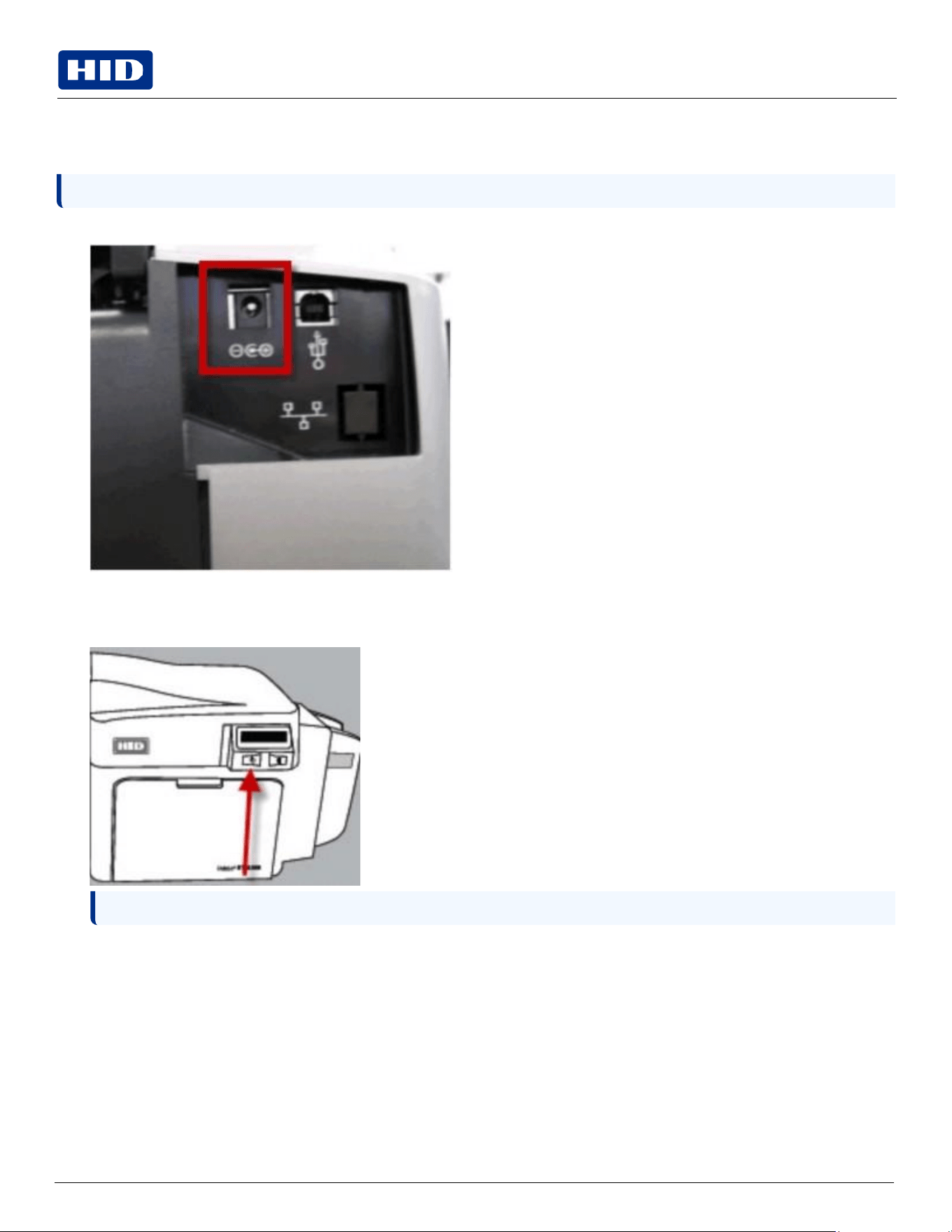
To connect power to the printer, follow this procedure.
1.
Plug the AC adapter power cable into the back of the printer.
2.
Plug the wall power cable into the AC power adapter.
3.
Plug the wall power cable into a standard 100-240VAC power outlet.
4.
Press the printer’s power button to power on the printer.

Public
Section 03
Print
driver
installation

Public
Powering
Trusted Identities
3.1
Introduction
HID®
FARGO®
DTC™1250e,
DTC1000Me,
DTC4250e,
and
DTCii
Plus
Card
Printer
User
Guide
This section describes the printer driver installation requirements and standard procedures. Requirements are listed
below. The DTC1250e, DTC1000Me, DTC4250e, and DTCii Plus print driver supports the following:
Windows Server 2003 (R1) 32-bit
Windows Server 2008 (R1) 32-bit with SP2
Windows Server 2008 (R1) 64-bit with SP2
Windows Server 2008 R2
Windows Server 2016
Windows Server 2019
Windows 7 32- and 64-bit
Windows 10 32- and 64-bit
For more information on supported operating systems, see hidglobal.com/support.
3.2
Driver installation instructions
Start the installation process by downloading the latest DTC1250e, DTC1000Me, DTC4250e, or DTCii Plus printer driver
from http://www.hidglobal.com/drivers; then, follow the InstallAware wizard screen prompts.
1.
Select
Install
the
Printer
Driver
to
start
the
driver
installation.
2.
Select
the
FARGO
Workbench
Utility
Program
to
install
the
Diagnostic
program.
3.
All versions of Windows require Administrator rights.
4.
From the Printer & Faxes, select Printing Preferences to set up the printer driver after it has been installed.
5.
Use the drop-down arrows to select the correct options for each printing preference.

Public
Section 04
Printer
preferences
Public
4.1
Introduction
This section provides an overview of the Printing Preferences tabs.
4.2
Card
tab
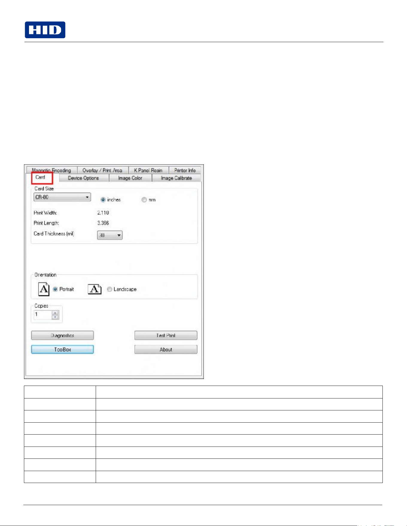
The Card tab provides options that define the basic characteristics of a card – the size and orientation. The Card tab also
provides access to helpful utilities and information:
Diagnostics
Test Print
Toolbox
About
Field
Description
Card
Size
Select
CR-80
or
CR-79.
Measurement
units
Select
inches
or
mm
(millimeters).
Print
Width
Displays
width
dimension
of
the
card.
Print
Length
Displays
length
dimension
of
the
card.
Card
Thickness
(mil)
Select the card thickness in mils.
Orientation
Select
Portrait
for
vertical
orientation
or
Landscape
for
horizontal
orientation.
Copies
Select the number of copies to print using Test Print.
Public
Field
Description
Diagnostics
Click Diagnostics to access the Workbench 3 utility. See the Workbench 3 User Guide or Workbench 3 Help
facility for more information. See 4.2.1 Toolbox window
Test
Print
Click Test Print to send one or more self-test prints to the printer.
Toolbox
Click the Toolbox button for access to the following Toolbox options:
Configuration
Calibrate
Ribbon
Clean
Printer
Advanced
Settings
About
Displays
the
About
screen.
4.2.1
Toolbox
window
The Card Toolbox window is displayed with the selection of the Toolbox button on the Card tab.
Public
Configuration
tab
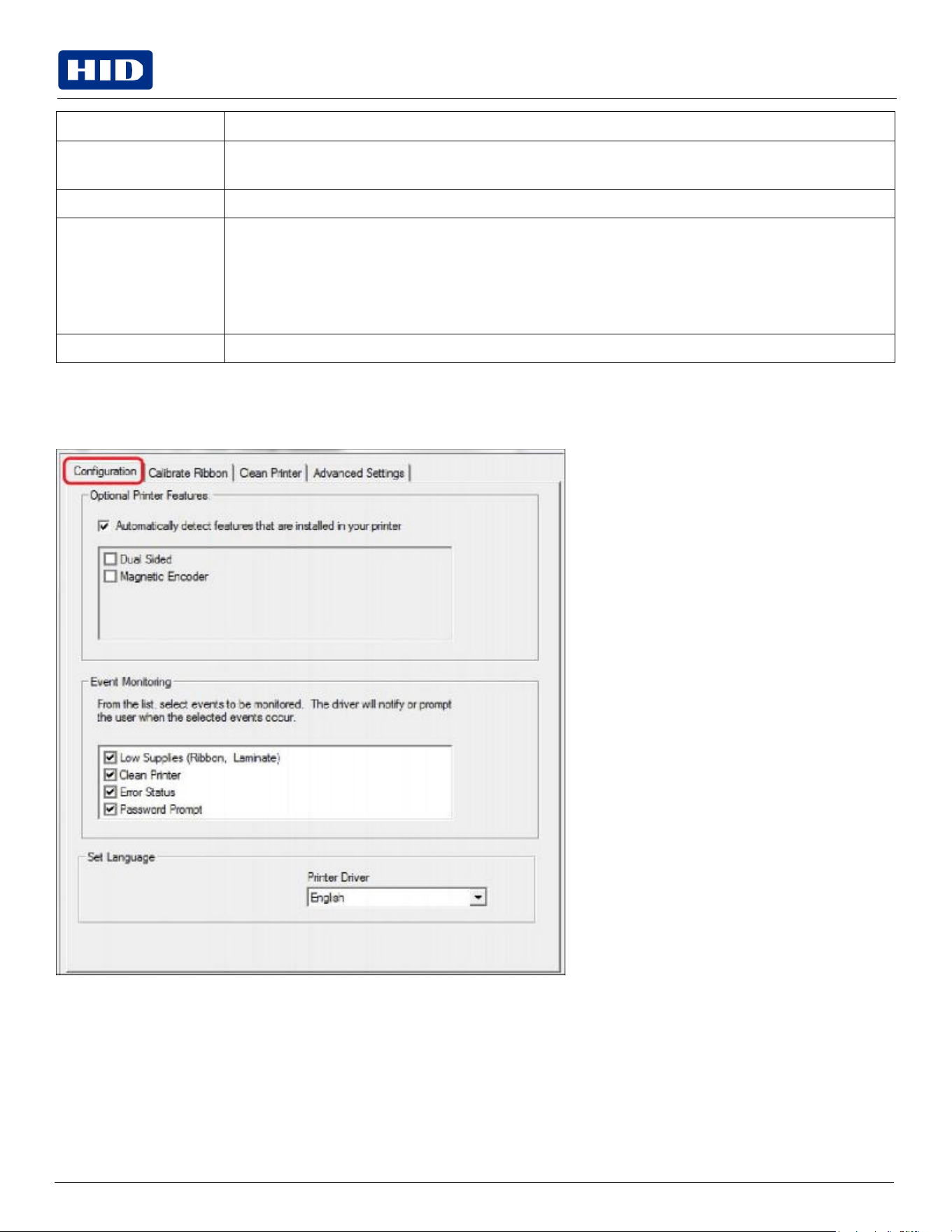
The Toolbox Configuration tab is used to show the currently installed Optional Printer Features, Event Monitoring, to set
the printer driver language and printer display language.
Set
Language
To switch between languages, select the preferred language from the Printer Driver drop-down menu. Click OK twice,
and then open the driver in the preferred language.
Calibrate
Ribbon
tab
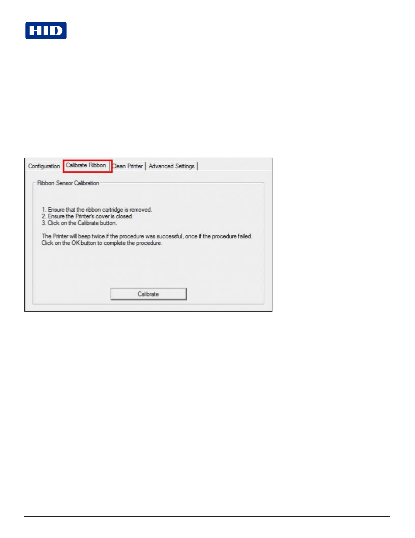
The Toolbox Calibrate Ribbon tab sends the Calibrate Ribbon command to the printer when you click the Calibrate
button. Follow the procedure displayed on this window.
Public
Clean Printer tab
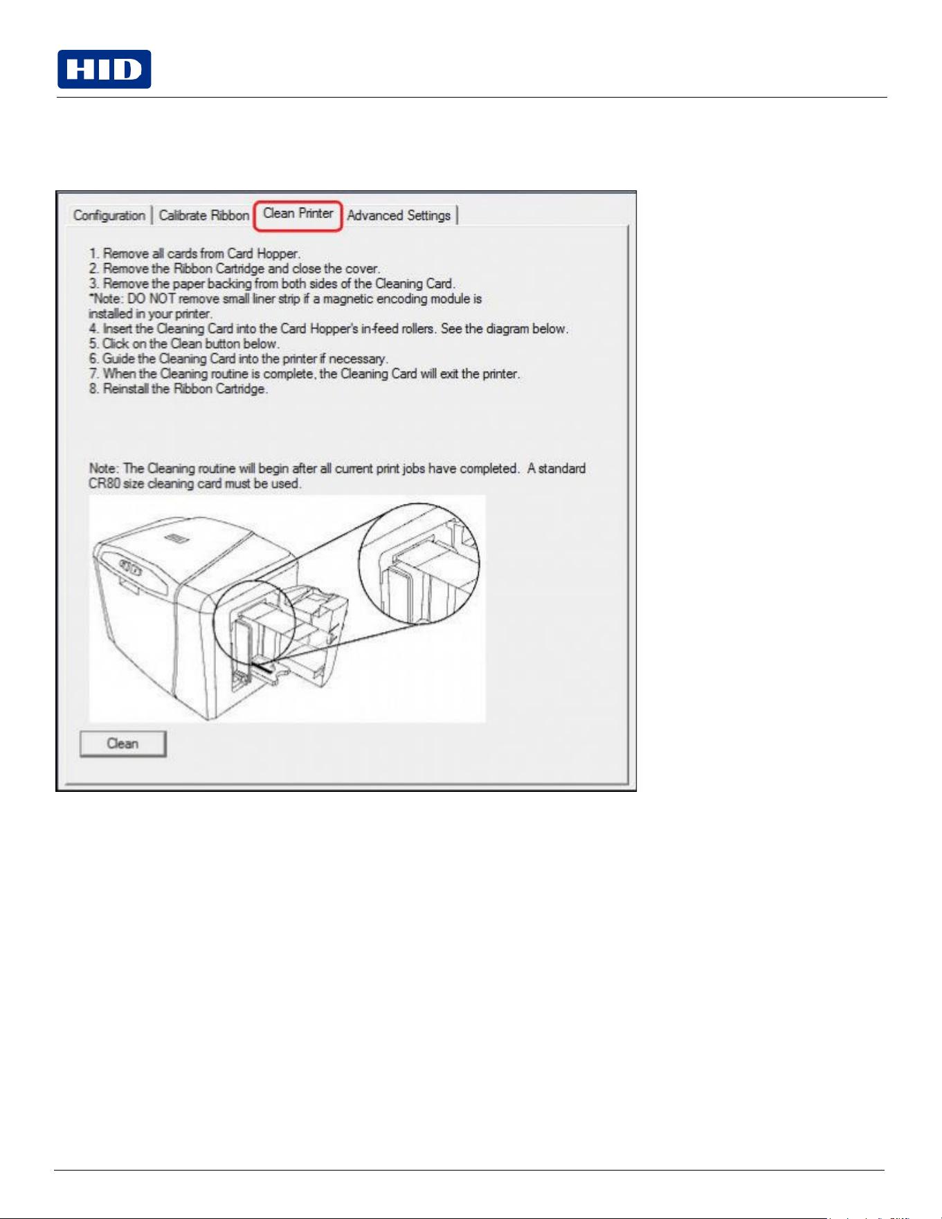
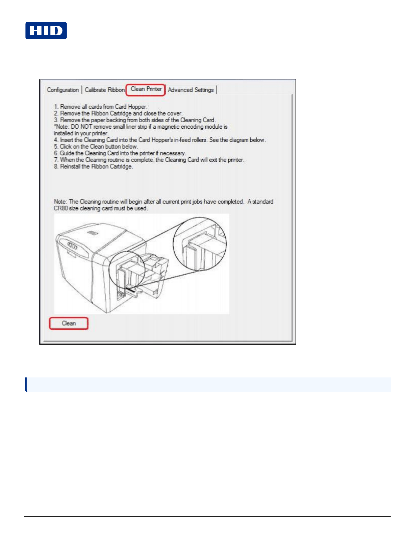
The Toolbox Clean Printer tab will launch the cleaning routing when the user clicks the Clean button. Follow this
procedure displayed on this window.
Public
Note: All messages are provided in English and French.
Safety
messages
(review
carefully)
Symbol
Critical
Instructions
for
Safety
Purposes
DANGER: FAILURE TO FOLLOW THESE INSTALLATION GUIDELINES CAN RESULT IN DEATH OR SERIOUS INJURY.
INFORMATION THAT RAISES POTENTIAL SAFETY ISSUES IS INDICATED BY A WARNING SYMBOL (AS
SHOWN TO THE LEFT).
To prevent personal injury, refer to the following safety messages before performing an operation preceded by this
symbol.
To prevent personal injury, always remove the power cord prior to performing repair procedures, unless otherwise
specified.
To prevent personal injury, make sure only qualified personnel perform these procedures.
Attention: Le non respect de ces consignes d'installation peut entraîner la mort ou des blessures graves. L'information qui
pose des problèmes de sécurité potentiels sont signalées par un symbole d'avertissement (comme illustré à gauche).
Pour éviter toute blessure, consultez les consignes de sécurité suivantes avant d'effectuer une opération précédée par ce
symbole.
Pour éviter toute blessure, débranchez toujours le cordon d'alimentation avant d'effectuer les procédures de réparation,
sauf indication contraire.
Pour éviter toute blessure, assurez-vous que seul le personnel qualifié est chargé de ces procédures.
Caution: This device is electrostatically sensitive. It may be damaged if exposed to static electricity discharges.
Information that raises potential electrostatic safety issues is indicated by a warning symbol (as shown to the
left).
To prevent equipment or media damage, refer to the following safety messages before performing an operation preceded
by this symbol.
To prevent equipment or media damage, observe all established Electrostatic Discharge (ESD) procedures while handling
cables in or near the circuit board and print head assemblies.
To prevent equipment or media damage, always wear an appropriate personal grounding device (e.g., a high quality wrist
strap grounded to avoid potential damage).
To prevent equipment or media damage, always remove the ribbon and cards from the printer before making any repairs,
unless otherwise specified.
To prevent equipment or media damage, take jewelery off of fingers and hands, as well as thoroughly clean hands to
remove oil and debris before working on the printer.
Public
Attention:
Ce dispositif est sensibles aux décharges électrostatiques. Il peut être endommagé s'il est exposé à des décharges
d'électricité statique.
Informations qui soulève des questions de sécurité potentiels électrostatiques est indiqué par un symbole d'avertissement
(comme illustré à gauche).
Pour éviter que l'équipement ou les dommages des médias, reportez-vous aux consignes de sécurité suivantes avant
d'effectuer une opération précédée par ce symbole.
Pour éviter que l'équipement ou des dommages médias, observer tous décharge établie électrostatique (ESD) des
procédures lors de la manipulation des câbles à ou près de la carte de circuit imprimé et assemblées de la tête
d'impression.
Pour éviter que l'appareil ou un support endommagé, portez toujours un dispositif approprié de mise à la terre personnelle
(par exemple, un bracelet de haute qualité à la terre pour éviter les dommages potentiels).
Pour éviter que l'appareil ou un support endommagé, retirez toujours le ruban et les cartes de l'imprimante avant
d'effectuer des réparations, sauf indication contraire.
Pour éviter que l'équipement ou les dommages des médias, prendre des bijoux hors de doigts et les mains, ainsi que les
mains propres pour enlever l'huile et les débris avant de travailler sur l'imprimante.
Cleaning
kit
As with any electronic device, internal components of the printer, such as the print head, may be damaged
if exposed to static electrical discharges. To avoid potential damage, always wear an appropriate personal
grounding device, such as a wrist strap (with integral resistor) connected to an ESD ground.
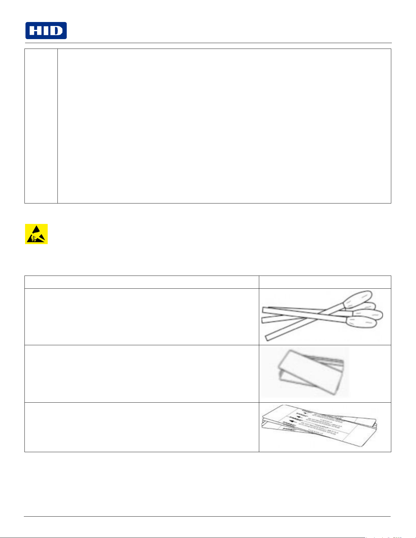
This cleaning kit provides you with the specialized cleaning supplies and the required cleaning procedures for you to
maintain your card printer/encoder. The following cleaning procedures will require less than 10 minutes.
Description
Supplies
(pictured)
Four (4) print head cleaning swabs are pre-moistened with 99.99% isopropyl alcohol for
cleaning the printer print head.
Three (3) alcohol cards are pre-moistened with 99.99% isopropyl alcohol for cleaning
the printer platen, and card feed rollers.
Ten (10) cleaning cards are provided with adhesive backing for cleaning the printer
platen and card feed rollers.
Public
Print head cleaning
1.
Turn off the printer and unplug the power cord from the printer.
2.
Remove the ribbon cartridge.
3.
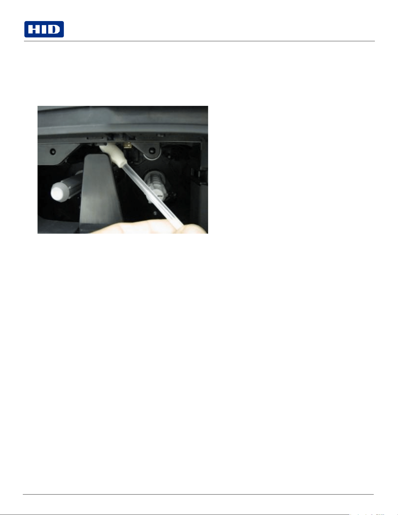
Open the print head cleaning swabs. Break it to moisten the tip.
4.
Swab the tip back and forth across the top of the print head.
5.
Allow to dry thoroughly before sending a print job.
Public
Note:
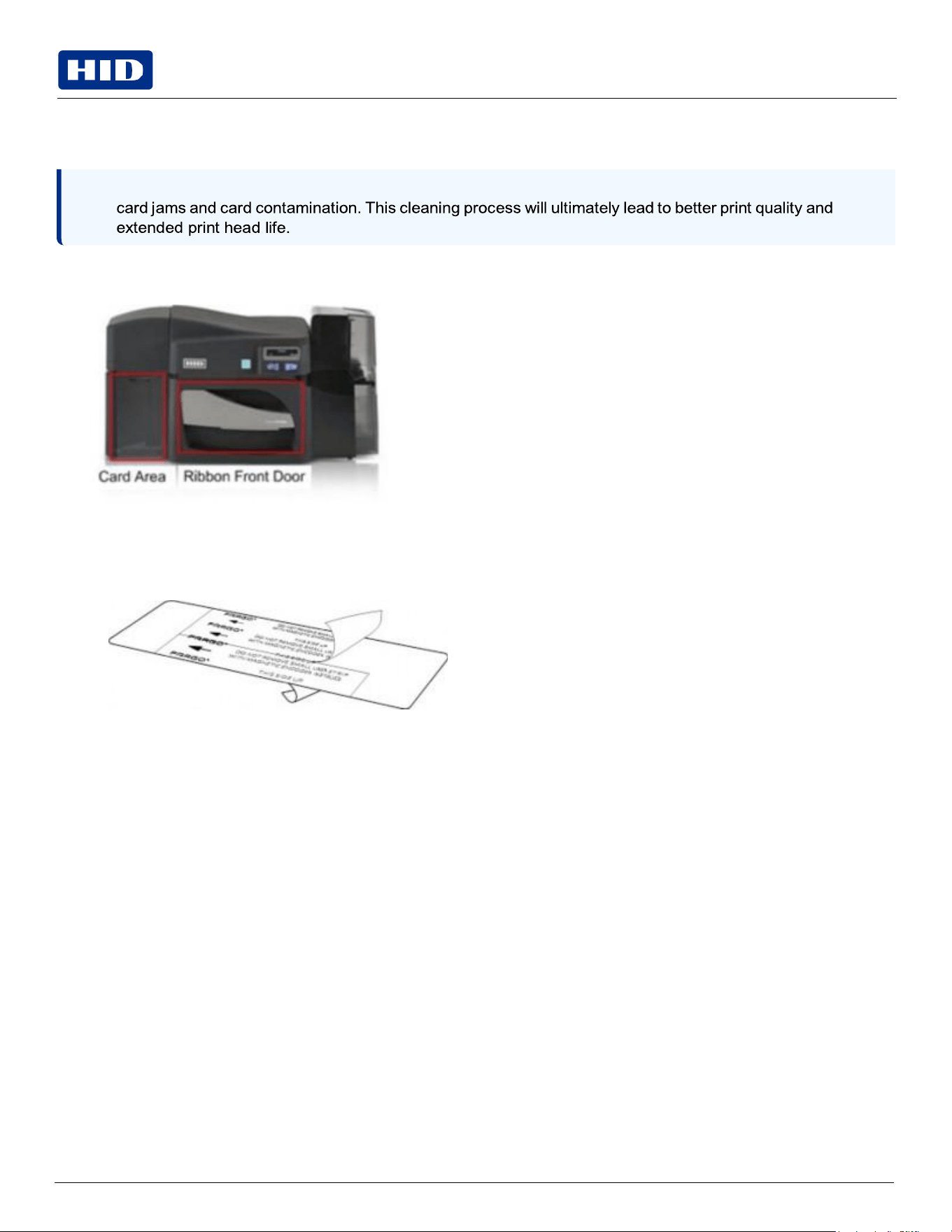
The card feed rollers move the card throughout the print process. Rollers should be kept clean to prevent
Cleaning the platen and the card feed rollers
Perform this procedure approximately every 1000 prints to maintain a consistent print quality.
1.
Open the printer front cover, remove the print ribbon and close the front cover.
2.
Remove all the cards from the printer input card hopper.
3.
Use the cleaning card from the cleaning kit and remove the adhesive backing from both sides of the card.
If your printer has a magnetic encoder installed, be sure to leave the small liner strip on top of the cleaning card
in place.
This small strip is needed to protect the magnetic head from the adhesives on the cleaning card.
4.
Insert the cleaning card into the single feed card slot until the card stops.
If your printer is equipped with a magnetic encoder, you must insert the cleaning card with the printed side up and
with the small liner strip towards the front of the printer.
Public
5.
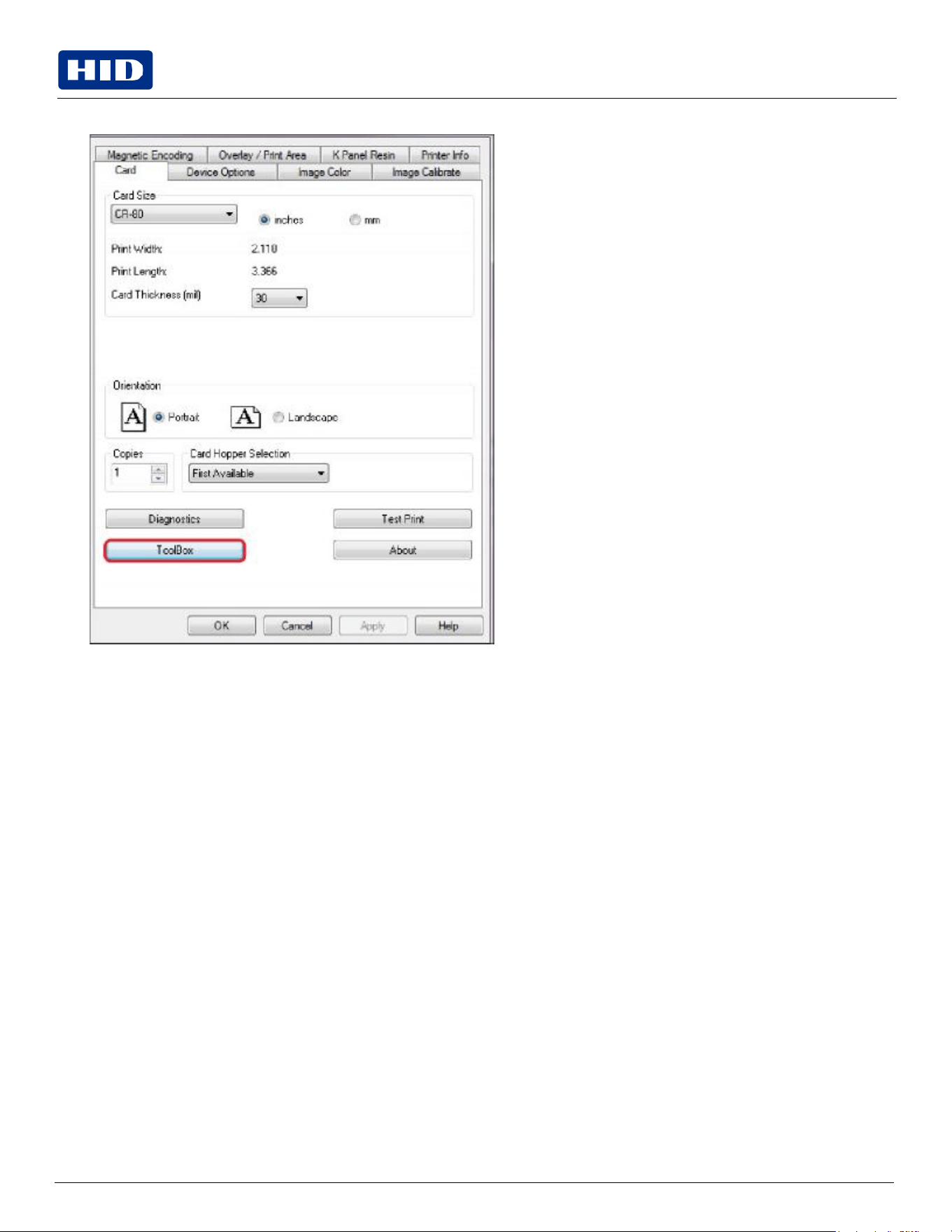
From your computer, open the printer driver and select Printing Preferences > Card tab > ToolBox.
6.
Select
the
Clean
Printer
tab.
Public
Note:
The printer has a durable casing that should retain its luster and appearance for many years.
7.
Click Clean.
The printer pulls in the cleaning card. The printer performs the automated cleaning procedure.
This procedure is designed to thoroughly clean the platen and the card feed rollers inside the printer.
Cleaning
the
printer’s
exterior
Clean the printer with a microfiber cloth only. Do not drip water into the printer. Dry thoroughly before printing.
Public
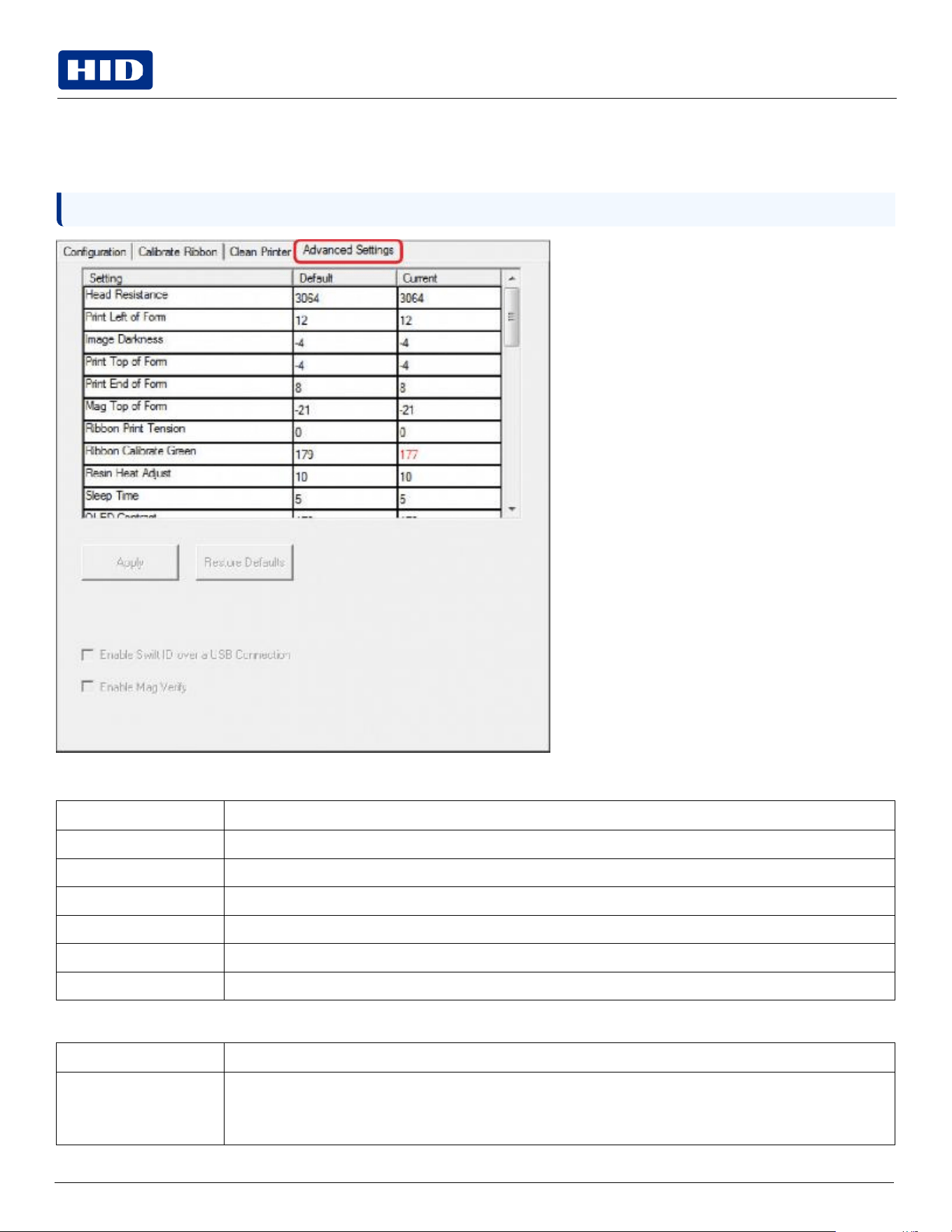
Note:
Select Restore Defaults to restore the internal default settings.
Advanced
Settings
tab
Use the Toolbox Advanced Settings tab for adjusting the internal printer settings, which are customized for every printer
at the factory and saved directly within the printer's memory.
Settings enable users to change the values for firmware settings by clicking on the Current column.
Field
Description
Setting
column
Displays label for setting. See the Setting column fields table below.
Default
column
Displays default value for setting.
Current
column
Displays current value for setting.
Apply
button
Applies
changed
values.
Restore
Defaults
button
Restores the default values.
Enable Mag Verify
Check
this
box
to
verify
that
the
data
is
written
to
the
tracks
correctly.
Setting
column
fields
Field
Description
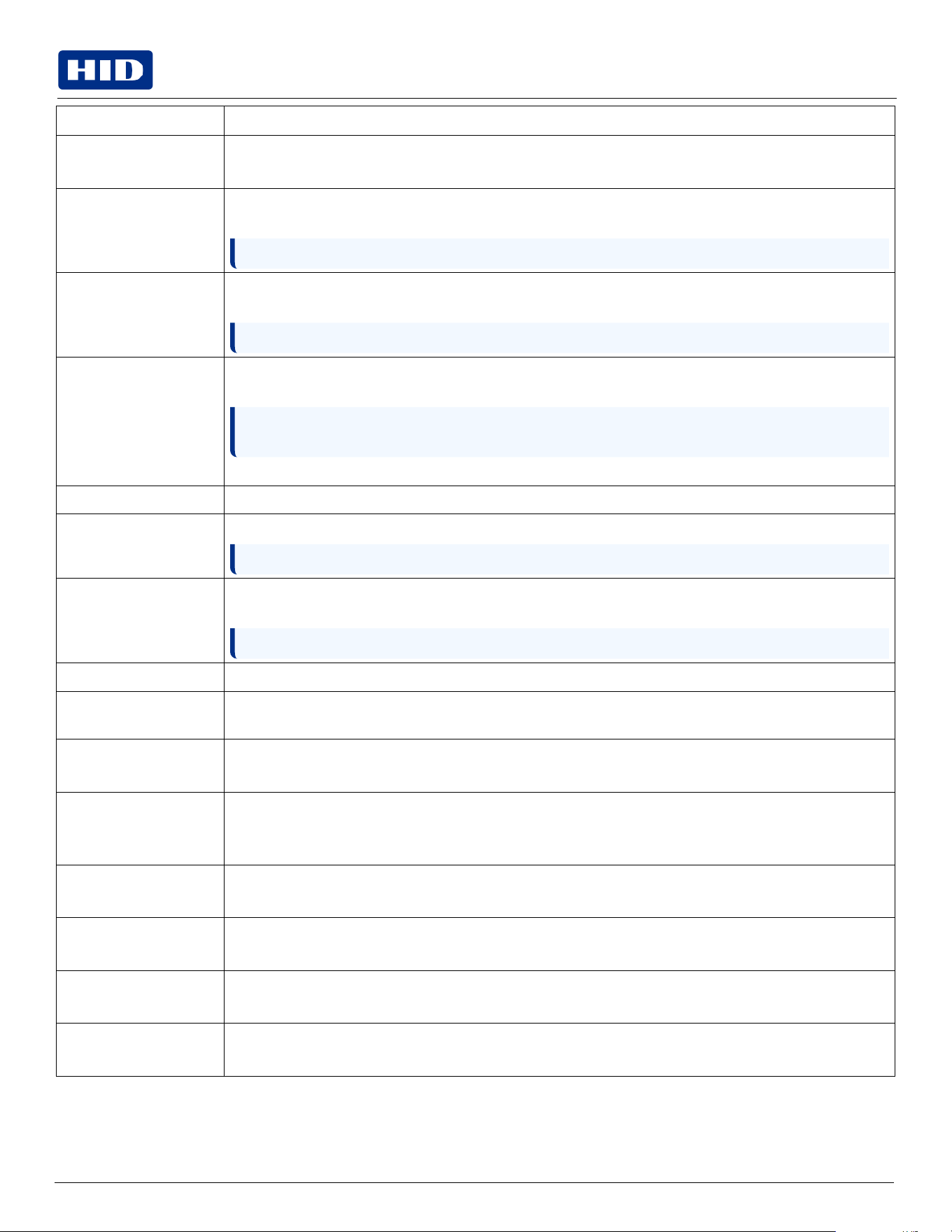
Head
Resistance
This is factory set. If the main board or the print head is replaced, then adjust this number. Locate the print
head setting number on the bottom of the print head.
The
number
reads
R=XXXX.
Public
Field
Description
Print
Left
of
Form
Use this option to adjust the vertical position of the printed image on the card; so it appears centered.
Maximum adjustment range is +/- 127.
Image
Darkness
Use this option to set the overall darkness of the printed image by increasing or decreasing the amount of heat
(used by the print head when printing).
Note:
If
the
value
is
set
too
high,
the
ribbon
may
jam
or
even
break.
Print Top of Form
Use this option to adjust the length-wise or horizontal position of the printed image on the card (so it appears
to be centered).
Note:
If
the
negative
value
is
set
too
high,
the
print
ribbon
may
break.
Mag Top of Form
Use this option to shift the starting point where the printer begins to encode the magnetic track data on the
card’s magnetic stripe.
Note: If the negative value is set too high, the printer may start encoding before the magnetic stripe
reaches the encoding head.
Maximum
adjustment
range
is
+/-
80.
Ribbon Print Tension
Use this option to increase or decreases the amount of tension (drag) on the ribbon during printing.
Ribbon Calibrate Green
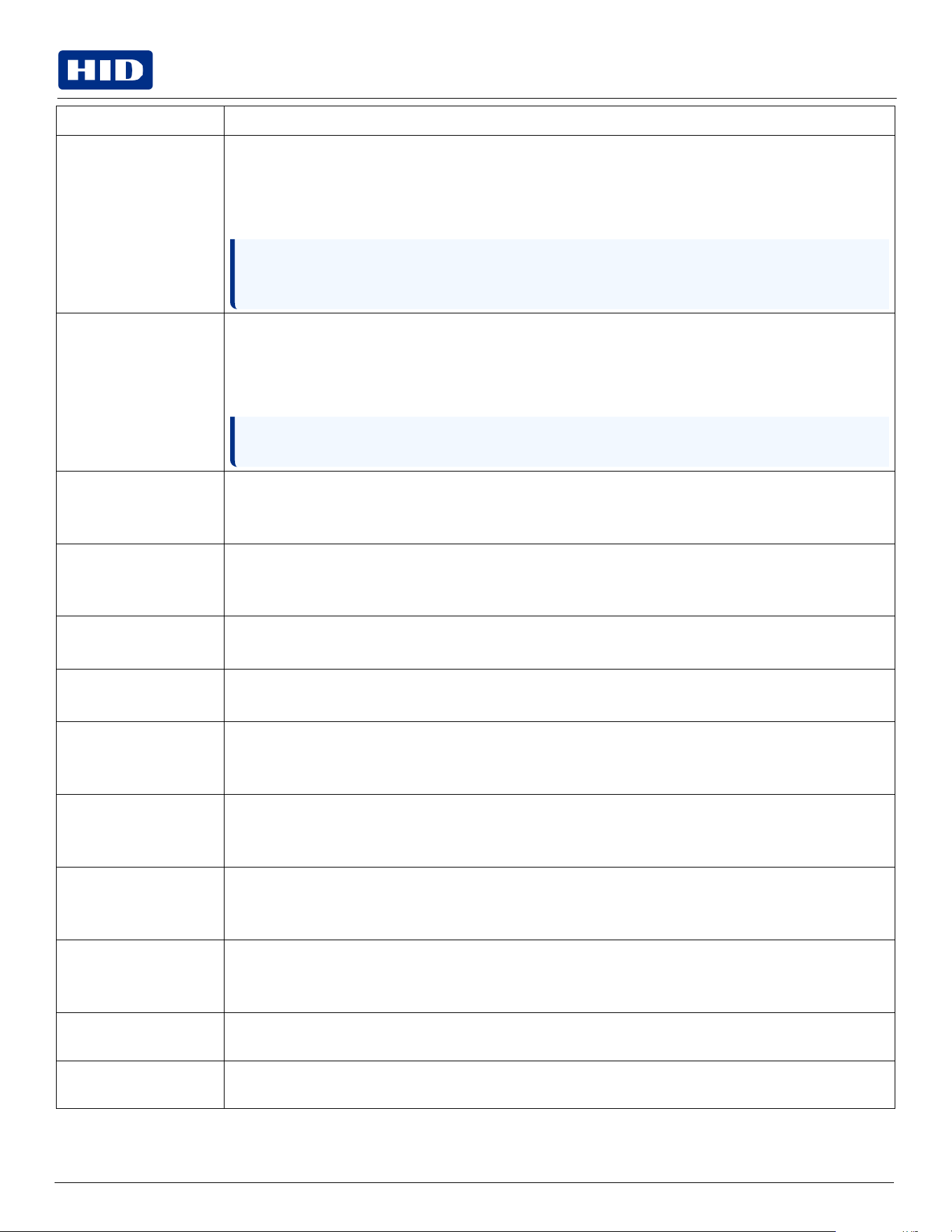
This is a calibration driven value and should not be adjusted.
Note: This is factory set and should not be changed unless directed
by a technician.
Resin
Heat
Adjust
Use this adjustment for black premium resin text and bar codes if they appear faded, too light or too dark.
Maximum adjustment range is +/- 100.
Note:
This
control
can
be
helpful
for
fine-tuning
the
transfer
of
resin
text
and
bar
codes.
Sleep
Time
This setting adjusts the number of minutes of inactivity before the printer enters a low power sleep state.
OLED Contrast (display
contrast)
Use this option to increase or decrease the contrast of the printer OLED (if applicable).
Ribbon Calibrate Blue
This setting is a calibration driven value and should not be adjusted.
It is factory set and should not be changed unless directed by a technician.
Cleaning
Rate
Use this option to adjust the number of cards printed before the printer displays a message indicating cleaning
is needed.
The default value is 3000 cards.
Mag
HI-Co
Voltage
Offset
This setting is a calibration driven value and should not be adjusted.
It is factory set and should not be changed unless directed by a technician.
Mag
Lo-Co
Voltage
Offset
This setting is a calibration driven value and should not be adjusted.
It is factory set and should not be changed unless directed by a technician.
Ribbon
Green
LED
Level
This setting is a calibration driven value and should not be adjusted.
It is factory set and should not be changed unless directed by a technician.
Ribbon
Blue
LED
Level
This setting is a calibration driven value and should not be adjusted.
It is factory set and should not be changed unless directed by a technician.
Public
Field
Description
Erase
Heat
Offset
Adjust
the
erase
temperature
for
the
rewritable
cards
as
needed.
Increase the current setting to cause more heat to be used in the erasing process.
OR
Decrease the current setting to cause less heat to be used in the erasing process.
Note: This option provides you the ability to control the print head heat level when the erase operation is
performed. Appropriate heat levels should be applied for the proper erase process. This setting
should be adjusted for proper erasure.
Write
Heat
Offset
Adjust
the
write
temperature
for
the
rewritable
cards
as
needed.
Increase the current setting to cause more heat to be used in the printing process of a rewritable card.
OR
Decrease the current setting to cause less heat to be used in the printing process of a rewritable card.
Note:
This
option
provides
you
the
capability
to
control
the
print
head
heat
level
when
the
write
operation
is performed. Appropriate heat levels should be applied for the proper writing process.
Flipper Home Offset
This setting is a calibration driven value and should not be adjusted. If the flipper unit is replaced and has not
been calibrated this value may need to be adjusted.
This setting
is
factory
set
and should
not
be
changed
unless
directed
by
a
technician.
Flipper Eject Height
Offset
This setting is a calibration driven value and should not be adjusted. If the flipper unit is replaced and has not
been calibrated this value may need to be adjusted.
This setting
is
factory
set
and should
not
be
changed
unless
directed
by
a
technician.
Mag Super-Co Voltage
Offset
This
option
changes
the
voltage
going
the
magnetic
head.
This setting
is
factory
set
and should
not
be
changed
unless
directed
by
a
technician.
Mag Medium-Co Voltage
Offset
This
option
changes
the
voltage
going
the
magnetic
head.
This setting
is
factory
set
and should
not
be
changed
unless
directed
by
a
technician.
Head
Home
Offset
This setting is a calibration driven value and should not be adjusted. If the print head assembly is replaced
then this value may need to be adjusted.
This setting
is
factory
set
and should
not
be
changed
unless
directed
by
a
technician
Head Print Offset
This setting is a calibration driven value and should not be adjusted. If the print head assembly is replaced
then this value may need to be adjusted.
This setting
is
factory
set
and should
not
be
changed
unless
directed
by
a
technician.
Head
Contact
Offset
This setting is a calibration driven value and should not be adjusted. If the print head assembly is replaced
then this value may need to be adjusted.
This setting
is
factory
set
and should
not
be
changed
unless
directed
by
a
technician.
Head
Queue
Offset
This setting is a calibration driven value and should not be adjusted. If the print head assembly is replaced
then this value may need to be adjusted.
This setting
is
factory
set
and should
not
be
changed
unless
directed
by
a
technician.
Head Card Thickness
Offset
Adjusts the card handling path to allow for variances in card thickness.
Head Smart Card Engage
Offset
Adjusts the position of the print head to allow smart card encoder contact.
Public
Field
Description
Head Mag Offset
Adjusts the print head for magnetic encoding.
Overlay
Heat
Adjust
Adjusts
the
temperature
setting
for
overlay
film.
10
Mil
Card
Queue
Offset
Adjusts the input queue for use with thick cards.
Erase
Speed
Adjusts the speed of the erasure process.
Standard Resin Head
Adjust
Use this adjustment for black standard resin text and bar codes if they appear faded, too light or too dark.
Maximum adjustment range is +/- 100.
This
control
can
be
helpful
for
fine-tuning
the
transfer
of
resin
text
and
bar
codes.
Printhead Smart Cue
Offset
Adjusts the card handling path to allow for variances in card thickness.
Public
4.3
Device
Options
tab
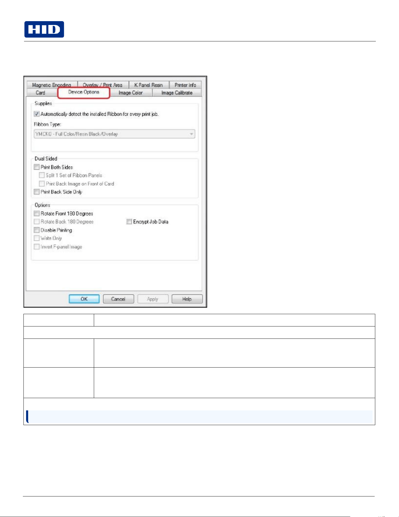
The Device Options tab configures the Supplies, Dual Sided, and Options features.
Field
Description
Supplies
Automatically detect the
installed Ribbon for every
print job
To verify that the ribbon type selected matches the installed ribbon. The printer changes the ribbon type to the
correct setting. The dialog indicates that the current setting has changed or that the current ribbon type is
correct.
Ribbon
Type
Manually selects the ribbon type. The available choices will vary, based on compatibility with your printer
model.
For rewritable
cards, select None
– Re-Writable.
Dual
Sided
Note: The Dual Sided area is grayed out when the printer is single-sided only.
Public
Note:
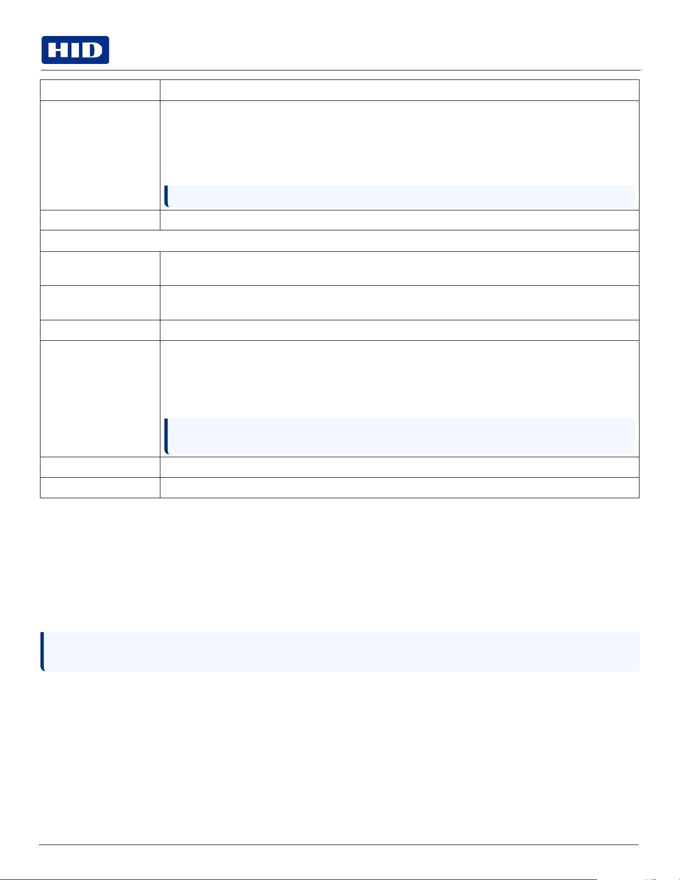
Any software program may be used to print the special florescent panel of the Ribbon to a card once the
driver and Workbench are set up correctly.
Field
Description
Print Both Sides
Select to automatically print the front and back sides of the card.
Split 1 Set of Ribbon Panels – Select to automatically print the front and back sides of the card using one
ribbon panel.
Print Back Image on Front of Card – Select to print the first page of a two-page print file on the card’s
backside. This option can also be used to print black resin on a smart card’s chip side.
Note: The second page of the file is printed on the card’s front side.
Print Back Side Only
Select
to
print
only
on
the
card’s
back
side.
Options
Rotate Front 180 Degrees
Select to change the orientation of the first page of the card design to accommodate the location of a chip or
RFID sensor.
Rotate
Back
180
Degrees
Select to change the orientation of the second page of the card design to accommodate the location of a chip
or RFID sensor.
Disable
Printing
Click
to
prevent
the
printer
from
printing.
Write
Only
Select to use rewritable cards. The default setup is for the printer to first erase the entire card and then write
new information on the card. There is no option to select specific areas to erase. However, to print or erase a
section, use the Overlay/Print Area tab. Select the specific area in the same manner as a print job with a color
ribbon. To erase many cards, use the FARGO Workbench Re-Writable Card Eraser option. It does not print. It
only erases.
Note: No ribbon is used with rewritable cards. Do not load a ribbon into the printer when using this
process. Printing on a rewritable card with a ribbon will ruin the card.
Invert
F-panel
Image
Select to change the portion of an image that is printed using a fluorescent film panel.
Encrypt
Job
Data
Select
to
encrypt
information
about
the
print
job
for
enhanced
security.
4.3.1
Fluorescent
panels
Fluorescent dye color is bright when black light is applied to it. The YMCFKO/YMCFKOK ribbon is an economical way to
add a fully customizable, incremental level of security to your photo identification cards.
Selecting
the
fluorescent
panel
ribbon
type
(DTC4250e
only)
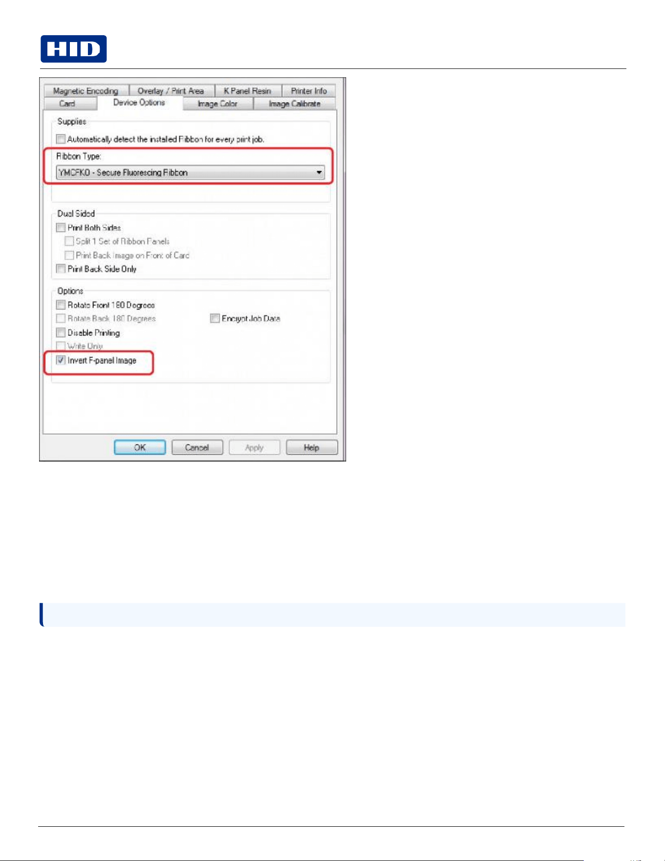
This process allows you to configure the data that is printed with the fluorescent panel of an YMCFKO/YMCFKOK
Ribbon.
These ribbons contain a yellow (Y), magenta (M), cyan (C), and resin black (K) panels to create a full color over-the-edge
printing identification card. In addition, the ribbon contains a dye-based fluorescing panel (F) which will allow you to print
a standard or one-to-one personalized fluorescing image that is completely invisible until exposed to ultraviolet light.
Public
Note: You can now print a unique fluorescent image, such as the card holder’s picture on each card.
Select Invert F-Panel Image to create a negative of the fluorescent image. This option refers to the ability to cause light
or white areas of the image to fluoresce and for dark colors to remain dark on the printed card when exposed to an
ultraviolet light. By default, the dark areas of the image fluoresce on the card. Lighter or white areas have no dye applied.
Creating
a
custom
fluorescent
image
using
the
YMCFKO
ribbon
There are three methods used to accomplish the creation of a custom fluorescent image when using the YMCFKO
Ribbon.
Printer Driver Method: The fluorescent panel image can be configured directly from the badge application software.
Asure ID Method: This method is described in Asure ID Software User Guide (PLT-01485). See the procedure relating to
the Fluorescent Panel Ribbon. For more detailed information visit the HID Global support website.
Workbench Method: This method is described in the Workbench 3 User Guide or the Workbench 3 Help facility. For
Help, enter Workbench by selecting Printing Preferences > Card tab > Diagnostics.
Public
4.4
Configuring
fluorescent
data
using
the
application
This process creates a fluorescent image on your card using a simple text string command in your badge application.
4.4.1
Creating
fluorescent
text
1.
Create a new text box in your badge application.
2.
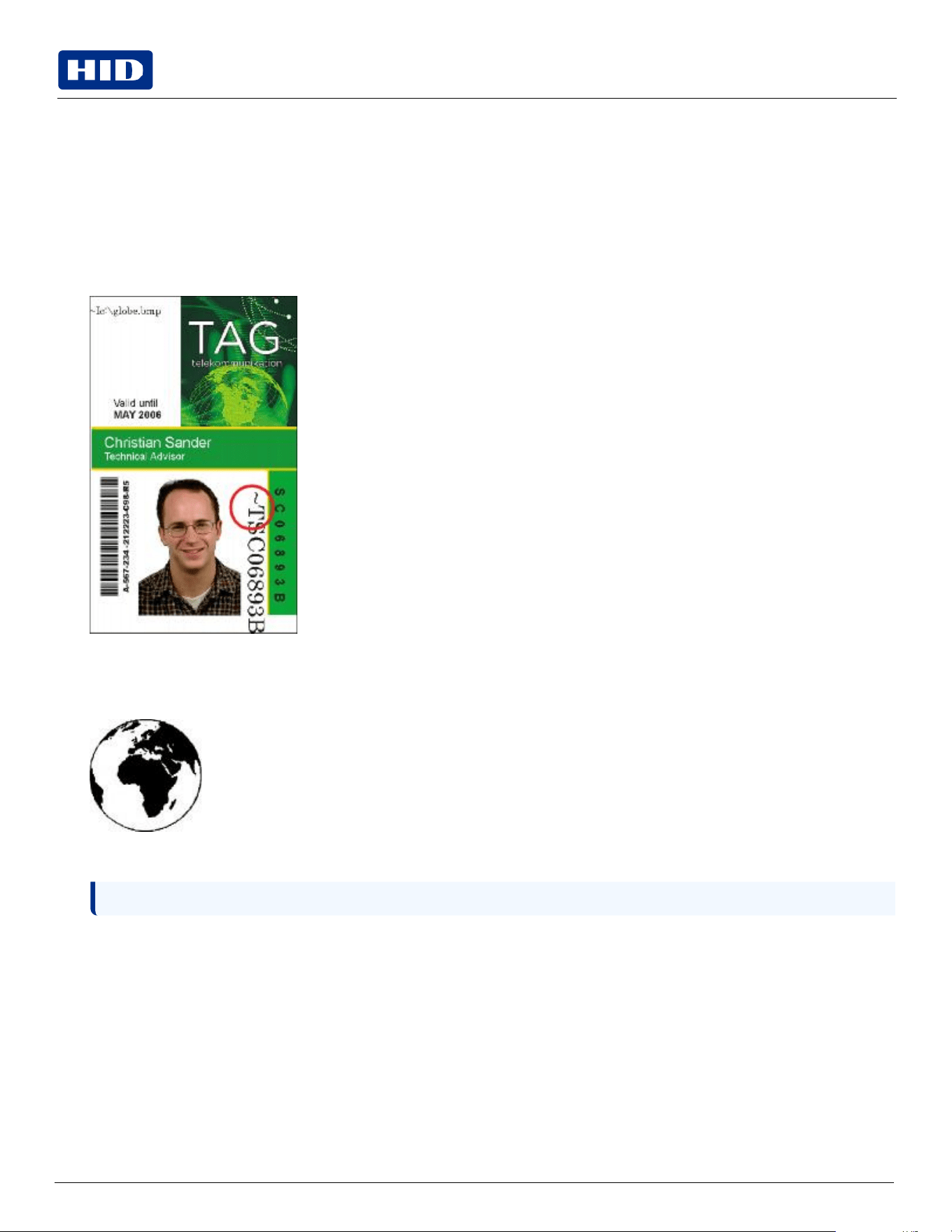
Type the TEXT that you want to appear as fluorescent and put a ~T before the start of the text with no space after
the ~T. The text will start on the card where the ~T begins.
4.4.2
Creating
a
fluorescent
image
1.
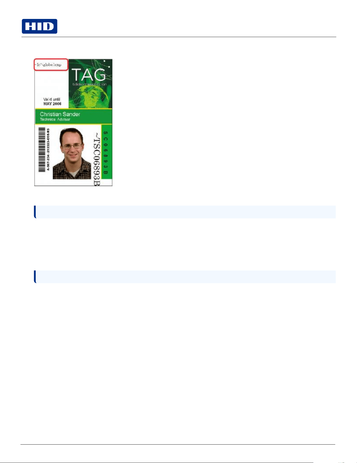
In a separate drawing program, create the image that you wish to fluoresce.
2.
Create the IMAGE in the actual size that you want it to appear on the card, and save it as a gray scale or 1-bit bmp
file on the root c:\ directory.
Note:
Do not put spaces in the file name.
Public
Note: The Automatically detect the installed ribbon for every print job button may also be used.
Note: This may improve the look of the person’s image if used for the Logo.
3.
Create a new text box in your badge application, and type ~I followed by the address of your image. The top left of
your image will start at the top left of your text box.
4.
Set up the printer driver preferences.
5.
Set the ribbon for YMCFKO in the Printing Preferences.
6.
Select Invert F-Panel Image to create a negative of the fluorescent image.
This refers to the ability to cause light or white areas of the image to fluoresce and dark colors to remain dark on
the printed card when exposed to a UV light.
This was requested because the fluorescent dye color is bright when black light is applied to it.
By default, the dark areas of the image will fluoresce on the card and the lighter or white areas will have no dye
applied.
7.
The printer prints the fluorescent BMP IMAGE at the ~I position on the card. Theh printer prints the fluorescent
TEXT at the ~T position on the card.
Public
4.5
Image
Color
tab
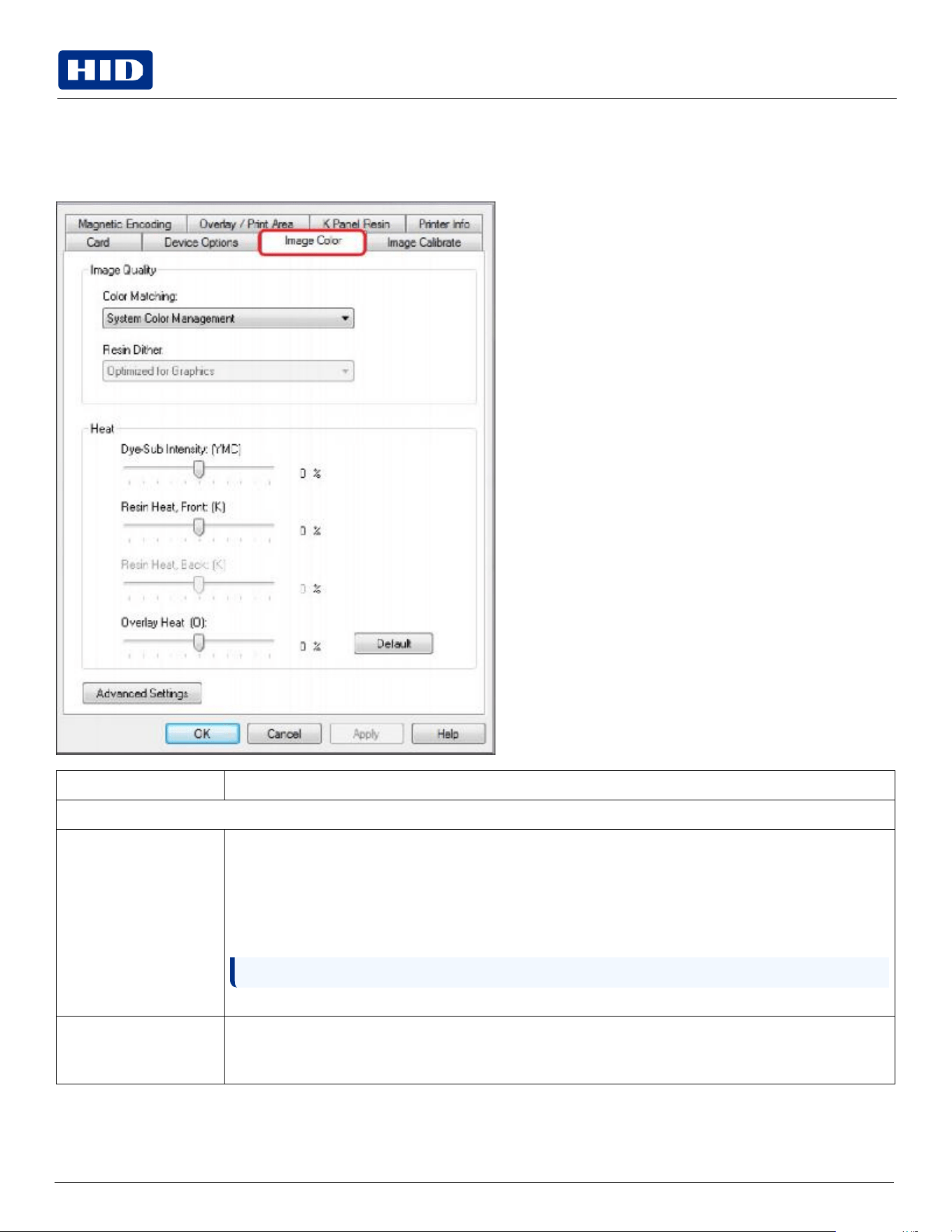
Use the Image Color tab to improve the quality of the image on the card. Image Color includes two areas, Image Quality
and Heat.
Field
Description
Image
Quality
Color
Matching
None – Select:
if
interested
in
print
speed
rather
than
print
color
if color correcting an image that has been previously printed, or
if using third-party color matching software
System Color Management – Select to perform color correction through a complex color-matching algorithm.
Note: This option shifts colors so they more closely match how they appear on screen.
Algebraic
–
Select
to
use
the
Algebraic
color-matching
algorithm.
Resin
Dither
Select the appropriate dither method according to the type of image to be printed. Graphics include images
such as drawings, clip art and logos. Photos include images such as photographs and photo-quality images.
This option affects objects printed with a resin-only ribbon.
Public
Field
Description
Heat
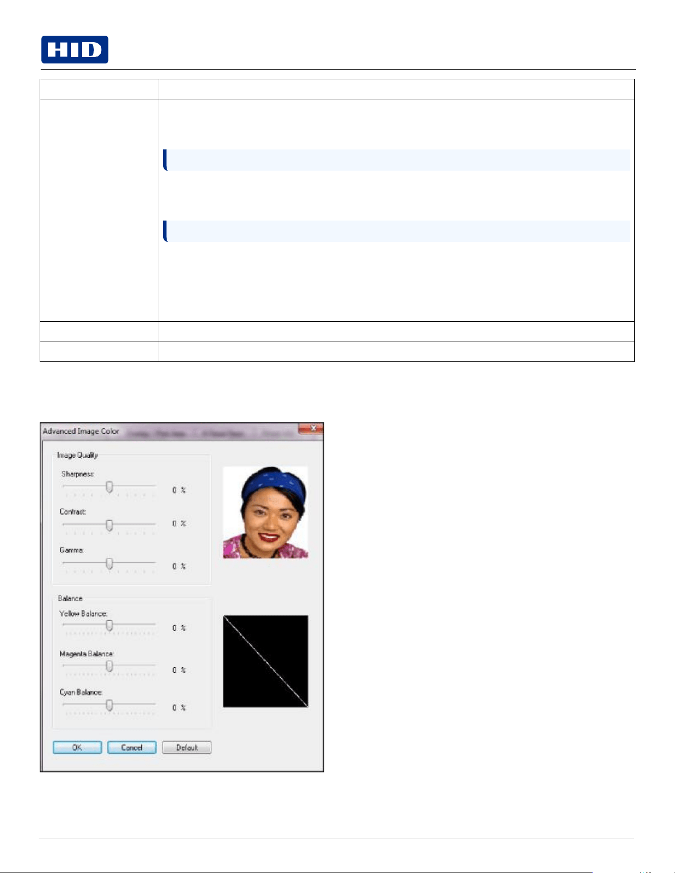
Dye-Sub Intensity (YMC) – Control the overall darkness and lightness of the dye-sub printed image by moving
the slider to the left to use less heat in the printing process, resulting in a lighter print. Move the slider to the
right to use more heat, resulting in a darker print.
Note: This slide only affects those images printed with dye-sublimation ribbon panels (YMC).
Resin Heat, Front (K) – Move the slider to the left to use less heat in the printing process, resulting in a lighter
or less saturated print. Move the slider to the right to use more heat, resulting in a darker or more saturated
print.
Note: This control can be helpful for fine-tuning the sharpness of resin text and bar codes.
Resin Heat, Back (K) – Move the slider to the left to use less heat in the printing process, resulting in a lighter
or less saturated print. Move the slider to the right to use more heat, resulting in a darker or more saturated
print.
Overlay Heat (O) – Move the slider to the left to use less heat in the printing process. Move the slider to the
right to use more heat.
Default
Click
this
button
to
return
all
options
to
their
factory
settings.
Advanced
Settings
See
the
Advanced
Settings
section.
4.5.1
Advanced
Settings
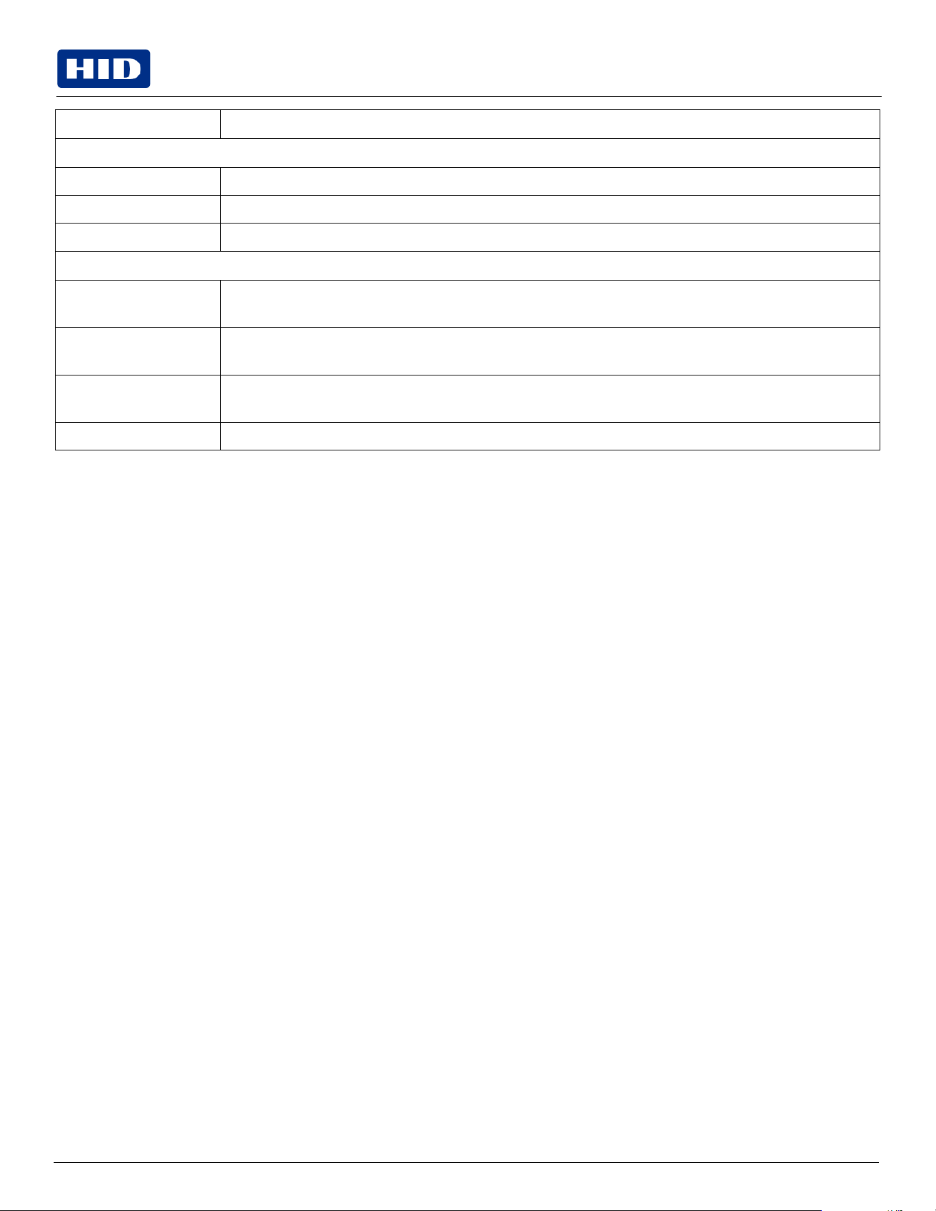
Click
the
Advanced
Settings
button
to
display
the
Advanced
Image
Color
window.
Public
Field
Description
Image
Quality
Sharpness
Move the slider to the right to sharpen the image. Move the slider to the left to decrease sharpness.
Contrast
Move the slider to the right to increase contrast in the image. Move the slider to the left to decrease contrast.
Gamma
Move the slider to the right to increase gamma in the image. Move the slider to the left to decrease gamma.
Balance
Yellow
Balance
Move the slider to the right to increase the amount of yellow in the image. Move the slider to the left to
decrease the amount of yellow.
Magenta
Balance
Move the slider to the right to increase the amount of magenta in the image. Move the slider to the left to
decrease the amount of magenta.
Cyan
Balance
Move the slider to the right to increase the amount of yellow in the cyan. Move the slider to the left to decrease
the amount of cyan.
Default
Click
this
button
to
return
all
options
to
their
factory
settings.
Public
4.6
Image
Calibrate
tab
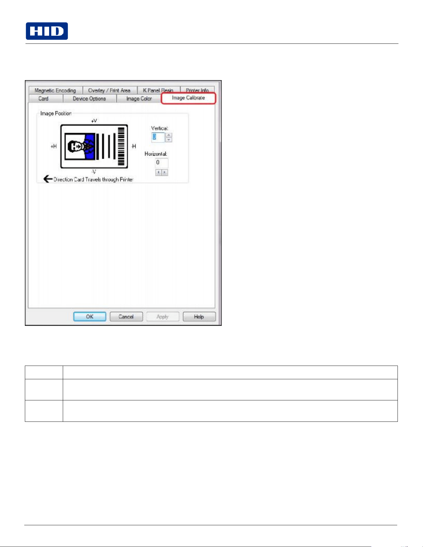
Use the Image Calibrate tab to control the position of the printable area in relation to the card.
Use the Vertical and Horizontal image position controls to adjust the position of the overall print area to be precisely
centered on a card. The maximum value for the Vertical and Horizontal adjustments is ±100 pixels (10 pixels = approx
0.03%, 0.8 mm).
Field
Description
Vertical
Use the Vertical adjustment to move the image toward the rear of the printer, if the adjustment is a positive number. Enter a
negative number to move the image toward the front of the printer.
Horizontal
Use the Vertical adjustment to move the image toward the rear of the printer, if the adjustment is a positive number. Enter a
negative number to move the image toward the front of the printer.
Public
4.7
Magnetic
Encoding
tab
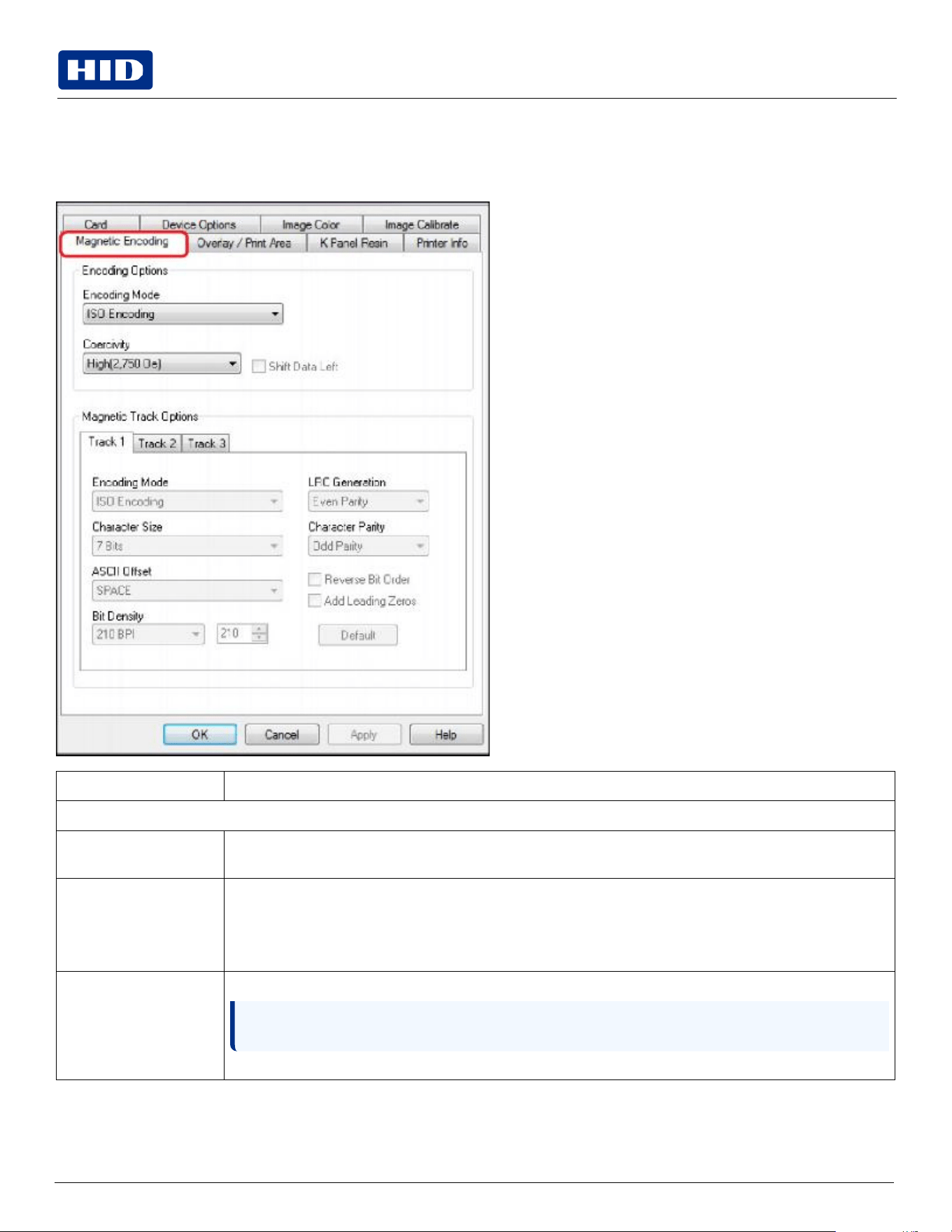
Select the Magnetic Encoding tab to display options for controlling the magnetic stripe encoding process. You can use
these options only if the printer has an optional Magnetic Stripe Encoding module installed.
Field
Description
Encoding
Options
Encoding
Mode
You can change the encoding mode and coercivity setting or modify the ISO standards for Tracks 1, 2 and 3.
This can be done by correctly modifying these magnetic encoding options.
ISO
Encoding
The
ISO
Encoding
option
sends
down
a
formatted
set
of
characters.
This selection activates the track tabs. However, all functions on the Track tabs are inactive or gray and
display ISO defaults, which are the defaults listed for each track below. The Shift Data Left check box remains
unchecked and inactive.
Custom
Encoding
If you select Custom Encoding, all options are active. The default is ISO Encoding.
Note: The defaults are the same as the ISO Encoding defaults. All functions on the Magnetic Track
Options tabs are active.
You
can
change
the
Magnetic
Track
Options
for
Tracks
1,
2
and
3.
Public
Field
Description
Character
Size
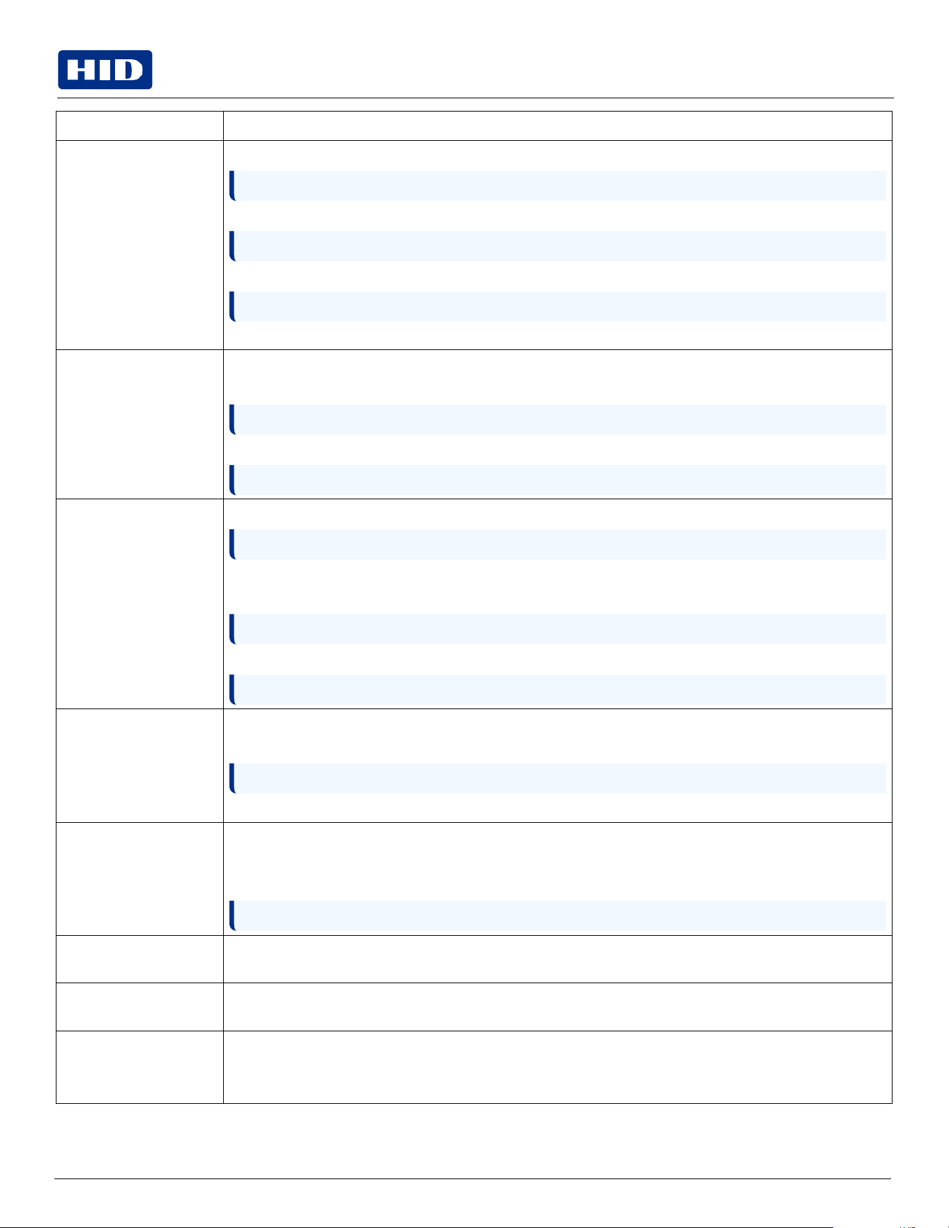
4 Bits to change the bits per character to 4 BPC.
Note: This is the default for Track 3.
5 Bits to change the bits per character to 5 BPC.
Note: This is the default for Tracks 2 and 3.
7 Bits to change the bits per character to 7 BPC.
Note: This is the default for Track 1.
8 Bits to change the bits per character to 8 BPC.
ASCII
Offset
NULL to change the ASCII Offset to NULL.
SPACE to change the ASCII Offset to SPACE.
Note: This is the default for Track 1.
ZERO to change the ASCII Offset to ZERO.
Note: This is the default for Tracks 2 and 3.
Bit
Density
75 BPI to change the bits per inch to 75 BPI.
Note: This is the default for Track 2.
128 BPI to change the bits per inch to 128 BPI.
210 BPI to change the bits per inch to 210 BPI.
Note: This is the default for Tracks 1 and 3.
Custom BPI, which enables the custom BPI text box.
Note:
The
lower
limit
is
75
and
upper
limit
is
210.
LRC
Generation
No LRC
to
change
the
LRC
Generation
to
none.
Even Parity to change the LRC Generation to Even Parity.
Note: This is the default for all tracks.
Odd Parity to change the LRC Generation to Odd Parity.
Character
Parity
No Parity to change the Character Parity to none.
Even Parity to change the Character Parity to Even Parity.
Odd Parity to change the Character Parity to Odd Parity.
Note:
This
is
the
default
for
all
tracks.
Reverse Bit Order
Reverse Bit Order is used to reverse the character bits and is used for the encryption of data in specific
programs.
Add
Leading
Zeros
Add Leading Zeros is used to add a set number of leading zeros to the magnetic string in order to move the
starting point of the encoded data in specific programs for encryption of data.
Raw
Binary
Encoding
The Raw Binary Encoding option will send down a raw binary string rather than a formatted set of characters.
The Coercivity drop-down function is active and the Shift Data Left check box is not active. All functions on the
Magnetic Track Options tabs are inactive except for Bit Density.
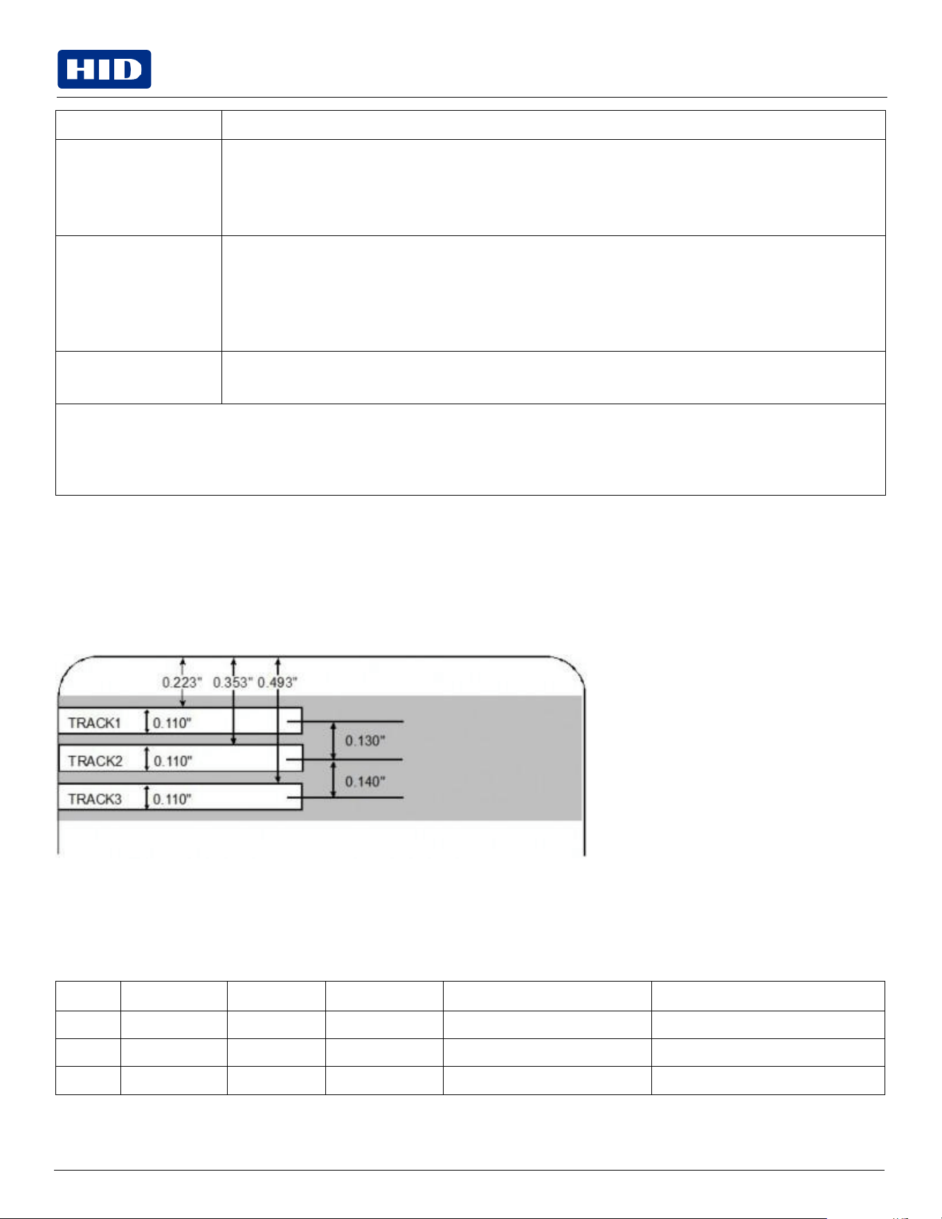
Public
Field
Description
JIS II Encoding
If
you
select
JIS
II
Encoding,
specific
standards
are
used.
This selection disables all the Magnetic Track Options tabs. It also disables the Coercivity drop-down function
and Shift Data Left check box option.
The default Coercivity is 600 Oe.
Coercivity
Select the Coercivity option (Oersted) that matches the card type.
High
Coercivity
4000
Oersted
FARGO
High
Coercivity
UltraCard
IIIs
are
2750
Oersted
Medium
Coercivity=600
Oersted
Low Coercivity =
300 Oersted
Shift Data Left
Select this option to shift the recorded magnetic data to the left-hand side of the card's Magnetic Stripe.
This is useful in situations that require cards to be readable with insert type readers.
Magnetic
Track
Options
The magnetic Encoding Module encodes onto tracks in accordance with an ISO 7811-2 magnetic stripe. For track locations, review the
display below. Tabs are available on the Magnetic Encoding tab with options for encoding data on each track. See 4.7.1 Magnetic Track
Options for more information.
4.7.1
Magnetic
Track
Options
The magnetic encoding module encodes onto tracks in accordance with an ISO 7811-2 magnetic stripe. For track
locations, review the display below. Tabs are available on the Magnetic Encoding tab with options for encoding data on
each track.
Reviewing the ISO Track Locations
Reviewing
the
sample
string
Track 1: ~1%JULIEANDERSON^1234567890?
Track 2: ~2;1234567890987654321?
Track 3: ~3;1234567890987654321?
Track
Start
sentinel
End
sentinel
Field
separator
Valid
characters
Maximum
number
of
characters
Track
1
%
?
^
ASCII
32-95
(see
table
below)
78
Track
2
;
?
=
ASCII
48-63
(see
table
below)
39
Track
3
;
?
=
ASCII
48-63
(see
table
below)
106
Public
Note:
When segmenting track data, the appropriate Ffeld separator (FS) must be used. The table below shows the
SS, ES, FS and the valid characters defined for each track.
Sending
the
track
data
Magnetic track data is sent in the form of text strings from the application software to the printer driver.
In order for the printer driver to differentiate between magnetic track data and the rest of the printable objects, specific
characters must be added to the magnetic data to be encoded.
These specify the data that is to be encoded the tracks to encode and mark the start and stop of the data string. In some
cases, these specific characters are automatically added to the string of track data by ID software applications.
In most cases, the user must carefully add these characters to the string of magnetic track data. If these characters are
not added to the track data, the text intended for the magnetic track will appear as printed text on the card. To avoid this,
track information must be entered as described below.
When entering track data, the ~ (tilde) character is entered first, followed by the track number (1, 2 or 3) on which the
data should encode. The data to be encoded follows the track number.
The first character of this data string must be the track's specific start sentinel (SS) and the last character must be the
specific end sentinel (ES).
The characters or data in between the SS and ES can include all of the valid characters specific to each track. The
number of these characters, however, is limited by each track's maximum character capacity.
Reviewing
the
ASCII
code
and
character
table
ASCII code
Character
ASCII code
Character
ASCII code
Character
32
space
56
8
80
P
33
!
57
9
81
Q
34
58
:
82
R
35
#
59
;
83
S
36
$
60
<
84
T
37
%
61
=
85
U
38
and
62
>
86
V
39
‘
63
?
87
W
40
(
64
@
88
X
41
)
65
A
89
Y
42
*
66
B
90
Z
43
+
67
C
91
[
44
‘
68
D
92
\
45
-
69
E
93
]
46
.
70
F
94
^
47
/
71
G
95
_
48
0
72
H
Public
ASCII code
Character
ASCII code
Character
ASCII code
Character
49
1
73
I
50
2
74
J
51
3
75
K
52
4
76
L
53
5
77
M
54
6
78
N
55
7
79
O
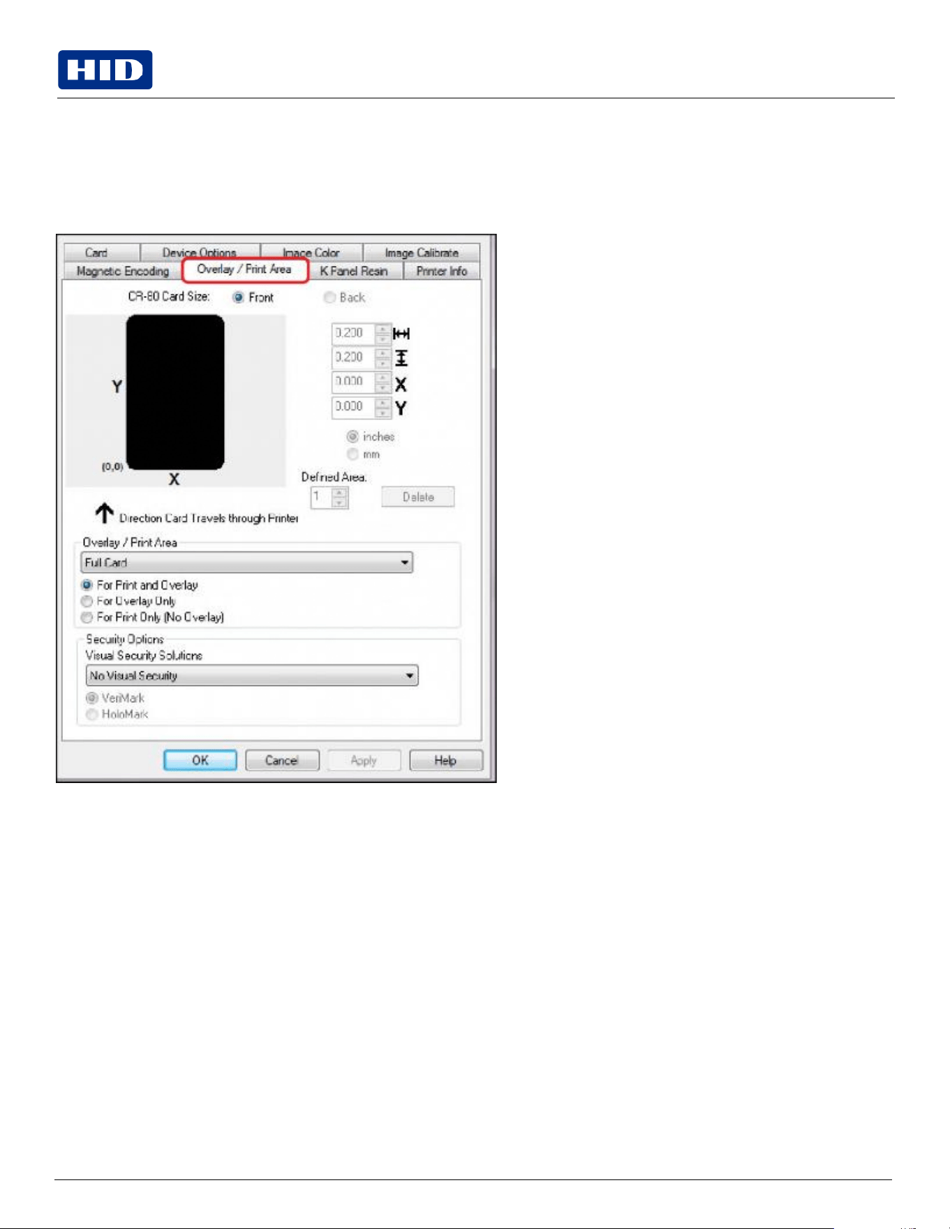
Public
4.8
Overlay / Print Area tab
Use the Overlay
/
Print Area tab to control and customize where the Overlay (O) panel and/or the print area appear on
the card. By default, this option is set to print and overlay the entire card.
The orientation of the card display area is determined by the orientation specified in your template.
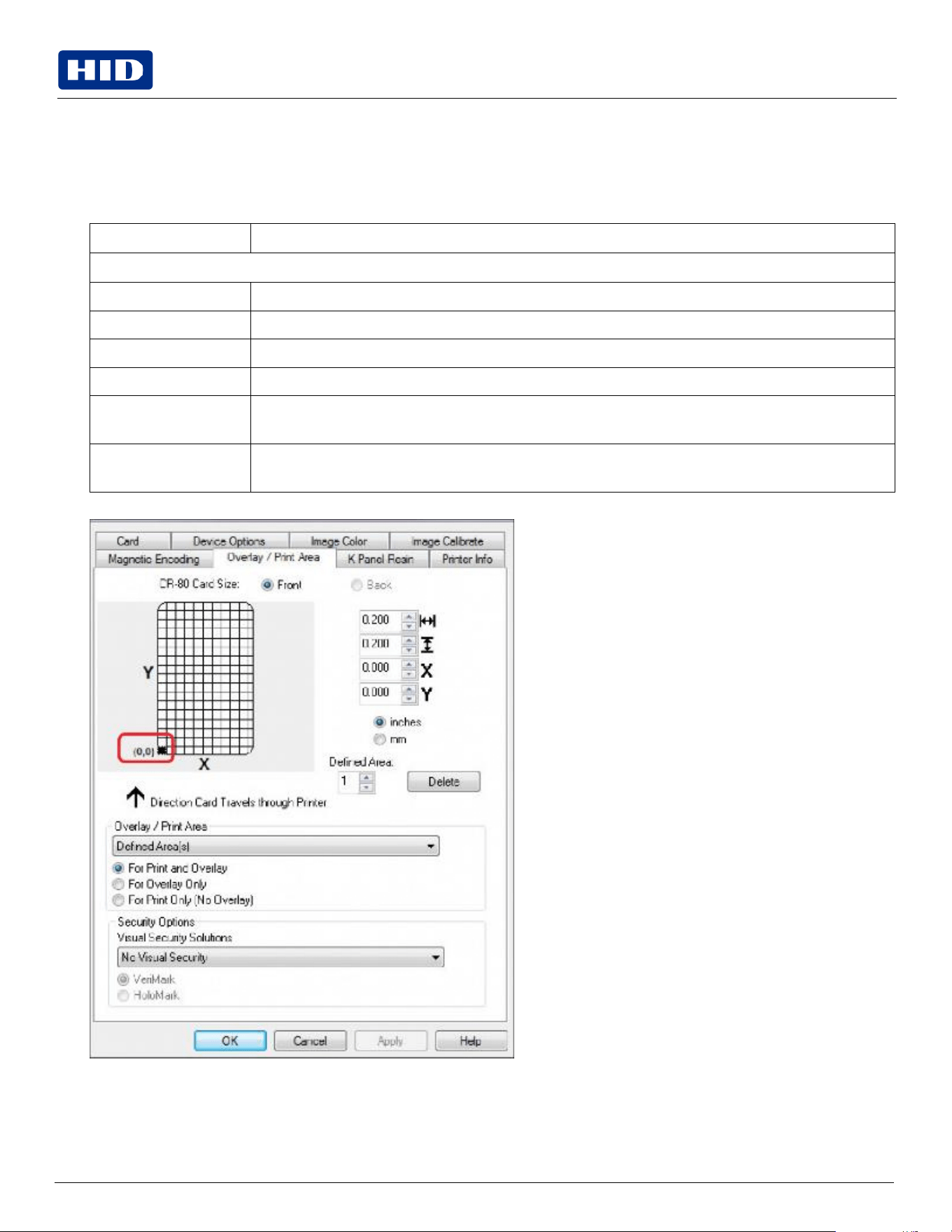
Public
4.8.1
Defining an overlay or print area
To define an overlay or print area:
1.
Select the Front or Back option to specify the side of the card to apply the area definition.
2.
Select Overlay/Print Area the drop-down and select the option that serves your purpose.
Field
Description
Overlay/Print Area (pull-down menu)
Full
Card
Select
this
option
to
overlay
and/or
print
the
entire
card.
Defined
Area(s)
Select
this
option
to
overlay
and/or
print
only
in
the
selected
and
define
an
area(s).
Undefined
Area(s)
Select this option to overlay and/or print in the space outside the selected and defined area.
Omit Smart
Chip Area
Select this option to overlay and/or print only in the space outside the standard location of a smart chip.
Omit
Mag
Strip
Area
Select this option to overlay and/or print only in the space outside the standard location of an ISO-
standard magnetic stripe.
Omit Signature Area
Select this option to overlay and/or print only in the space outside the standard location of a signature
panel.
3.
When an option is selected, a default blacked area appears on the card design area grid.
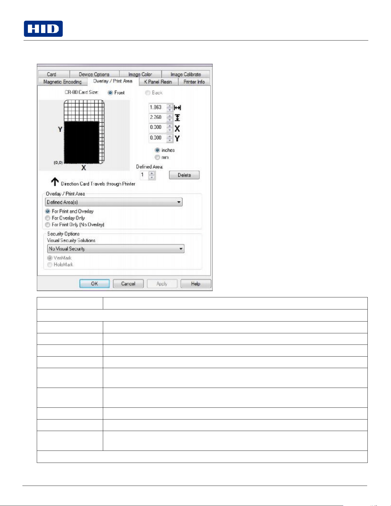
Public
4.
Select and drag to enlarge the area and move it to the preferred location on the card. The size and coordinates of
the area will update the number fields (inches or mm).
Field
Description
Overlay/Print
Area
Full
Card
Select
this
option
to
overlay
and/or
print
the
entire
card.
Defined
Area(s)
Select
this
option
to
overlay
and/or
print
only
in
the
selected
and
define
an
area(s).
Undefined
Area(s)
Select this option to overlay and/or print in the space outside the selected and defined area.
Omit Smart
Chip Area
Select this option to overlay and/or print only in the space outside the standard location of a smart chip.
Omit
Mag
Strip
Area
Select this option to overlay and/or print only in the space outside the standard location of an ISO-
standard magnetic stripe.
Omit Signature Area
Select this option to overlay and/or print only in the space outside the standard location of a signature
panel.
For Print and Overlay
This
option
applies
the
defined
area
to
both
the
print
and
overlay
processes.
For
Overlay
Only
The defined are applies only to the overlay process. The entire card prints and only the overlay is affected.
For Print Only (No
Overlay)
The defined are applies only to the print process. Overlay is disabled.
Security
Options
Public
Field
Description
Visual
Security
Solutions
Use this field to enable and select a visual security option. When one of the options is selected, the
Overlay/Print Area feature is disabled.
This field presents options based on the orientation of the card in the template. The default value for all
cards is No Visual Security.
Landscape designs offer:
A – Upper Left
B – Upper Right
C – Lower Left
D – Lower Right
Portrait
designs
offer:
E – Upper Left
F – Upper Right
G – Lower Left
HoloMark
Use
this
option
for
hologram
security.
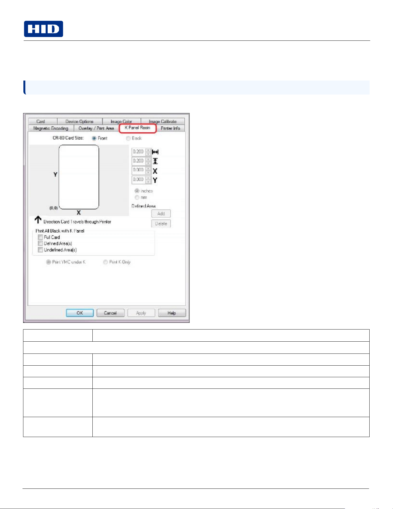
Public
Note:
Orientation of the card display area is determined by the orientation specified in the template.
4.9
K
Panel
Resin
tab
Use the K Panel Resin tab to control where the resin black (K) Panel of a full-color ribbon is printed. If a ribbon without a
K resin panel is installed in your printer, these options are grayed out and unavailable.
See
4.8.1
Defining
an
overlay
or
print
area
for
information
on
the
card
size,
etc.
Field
Description
Print
All
Black
with
K
Panel
Full
Card
Select
this
option
to
overlay
and/or
print
the
entire
card.
Defined
Area(s)
Select
this
option
to
overlay
and/or
print
only
in
the
selected
and
define
area(s).
See
4.9.1
Defined
area.
Undefined
Area(s)
Select this option to overlay and/or print in the space outside the selected and defined area.
Print
YMC
under
K
Select this option to print all black in the designated areas with the yellow (Y), magenta (M) and cyan (C)
ribbon panels directly beneath the resin black (K) panel. This combination provides a gradual transition
between the resin black text or bar code.
Print K Only
Select this option to print using the resin black (K) panel onto a white background to maximize the sharpness
of printed text and bar codes.
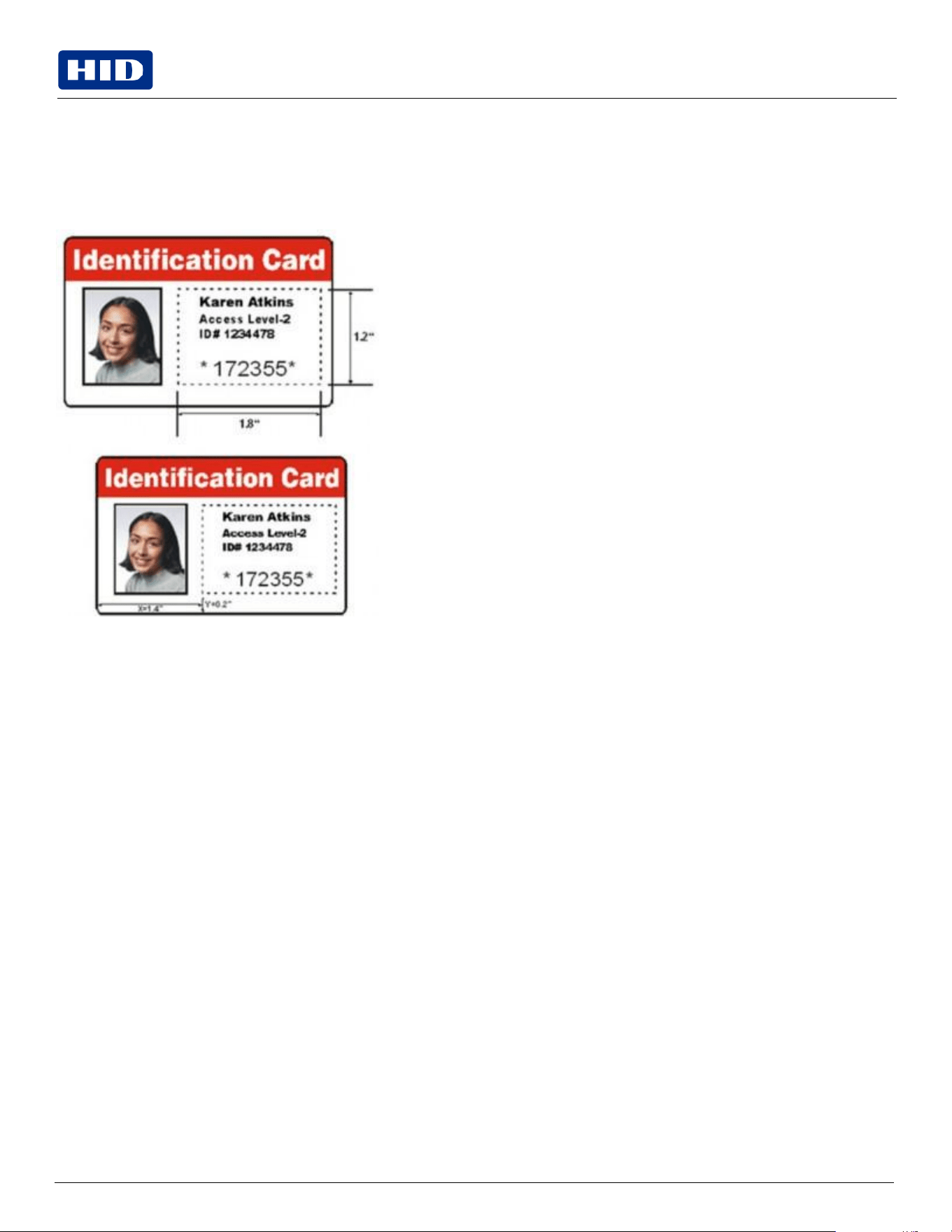
Public
4.9.1
Defined
area
The Defined Area option can be used with the K Panel Resin or the Overlay / Print Area tabs to define one or more
specific areas.
In the samples, the defined area is indicated by the dashed outline.
Method
for
defining
a
single
area
1.
On
the
Overlay / Print Area
or
K Panel Resin
tab,
select
Defined Area(s)
.
2.
Print a card and look at it in the same orientation as when it exits the printer.
3.
Measure the total size of the area and enter the dimensions into the dimension boxes.
4.
Measure from the lower-left corner of the card to the lower-left corner of the defined area and enter the values into
the X and Y boxes.
Method
for
defining
multiple
areas
1.
On
the
Overlay / Print Area
or
K Panel Resin
tab,
select
Defined Area(s)
.
2.
Print a card with a defined area and look at it in the same orientation as when it exits the printer.
3.
Measure the defined area location based on the printed card.
4.
To define another area, click the Defined Area up-arrow.
5.
Use the Defined Area arrows to navigate back and forth from area to area.
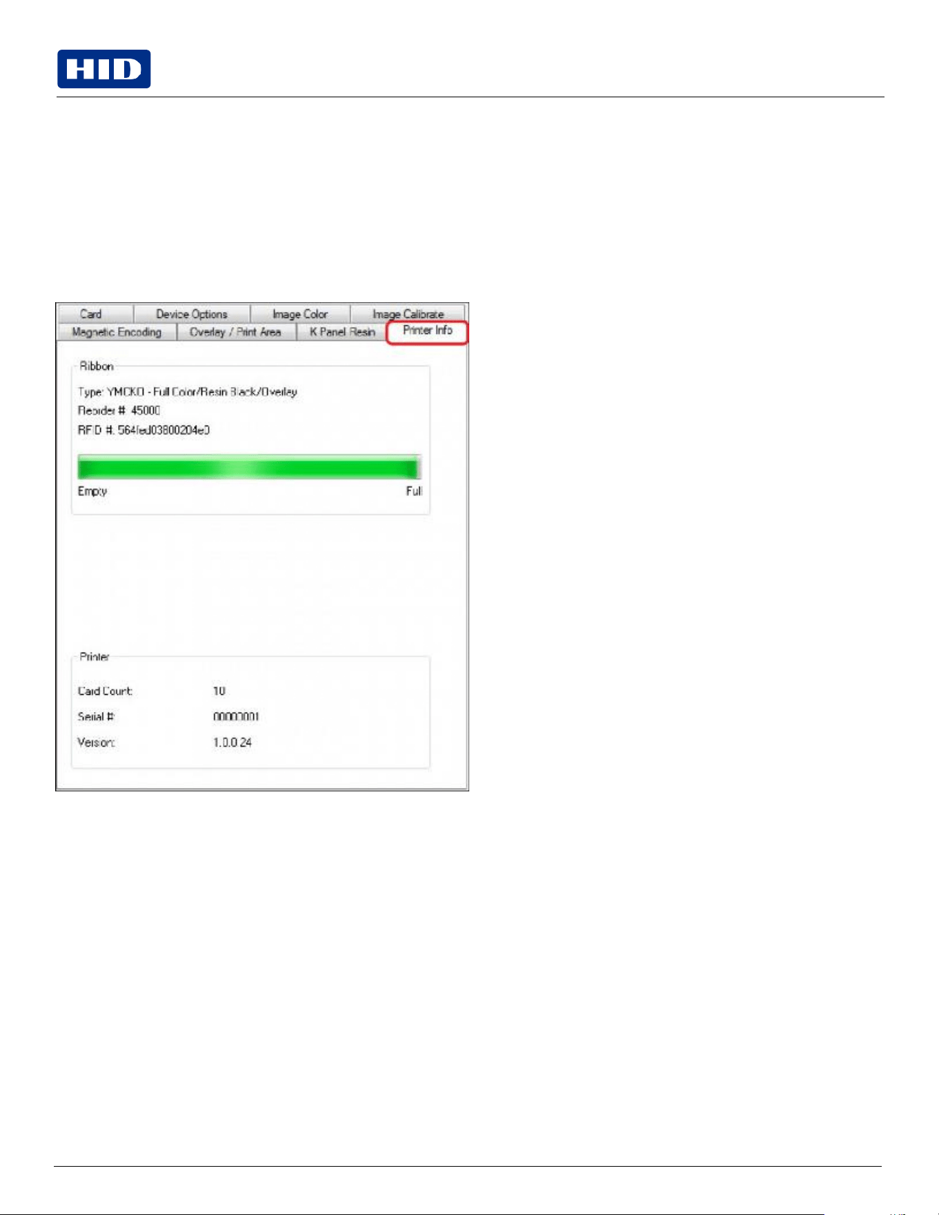
Public
4.10
Printer Info tab
Use the options on this tab to view information about the medias installed on the printer:
Ribbon
Card Count
Printer Serial #
Firmware Version
Reorder Number

Public
Section 05
System
overview
-
troubleshooting

Public
Note:
The print ribbon encoder detects the number of revolutions required to use an entire color panel.
5.1
Sequence
of
operations
Knowing the sequence of the printer operation helps when troubleshooting the printer.
1.
File information is received from the PC.
2.
Printer compares the installed ribbon type stored in memory with the ribbon type command that was sent from the
printer. If the ribbon type does not match, the Pause button (on the right) flashes.
3.
The print stepper motor engages.
4.
The card feed sensor detects the leading edge of the card and the head lift stepper engages to disengage the input
lever.
5.
The card feeds through for the alignment pass.
6.
The card feed stepper motor engages to queue card for magnetic encoding (if applicable).
7.
The encoded data is written to the card (if applicable).
8.
The magnetic encoder verifies while the stepper reverses the card (if applicable).
9.
The print ribbon drive engages (if not already at the yellow panel).
10.
The print ribbon sensor looks for the yellow panel.
11.
The print stepper motor engages.
12.
The card feed sensor detects the leading edge of card.
13.
The print stepper motor queues card to the middle of the platen roller. All stop.
14.
The print head lift motor engages to the print position.
15.
The print cover sensor checks for closed state.
16.
The print stepper motor engages.
17.
The ribbon drive motor engages.
18.
The image data is burned by the print head until the image data is depleted. All Stop.
19.
The thermistor engages the print head cooling fan to maintain proper operating temperature.
20.
The headlift motor engages to the queue position.
21.
The print stepper motor engages.
22.
The print ribbon drive engages.
23.
After ribbon advances a few encoder clicks, assume the ribbon is free of card. All stop.
24.
Repeat Steps 9 through 22 for the appropriate number of color/overlay Panels.
25.
Either the card is ejected from the singled-sided printer or the card feed stepper engages to queue the card for the
flipper table for the dual-sided printer.
26.
All stop.
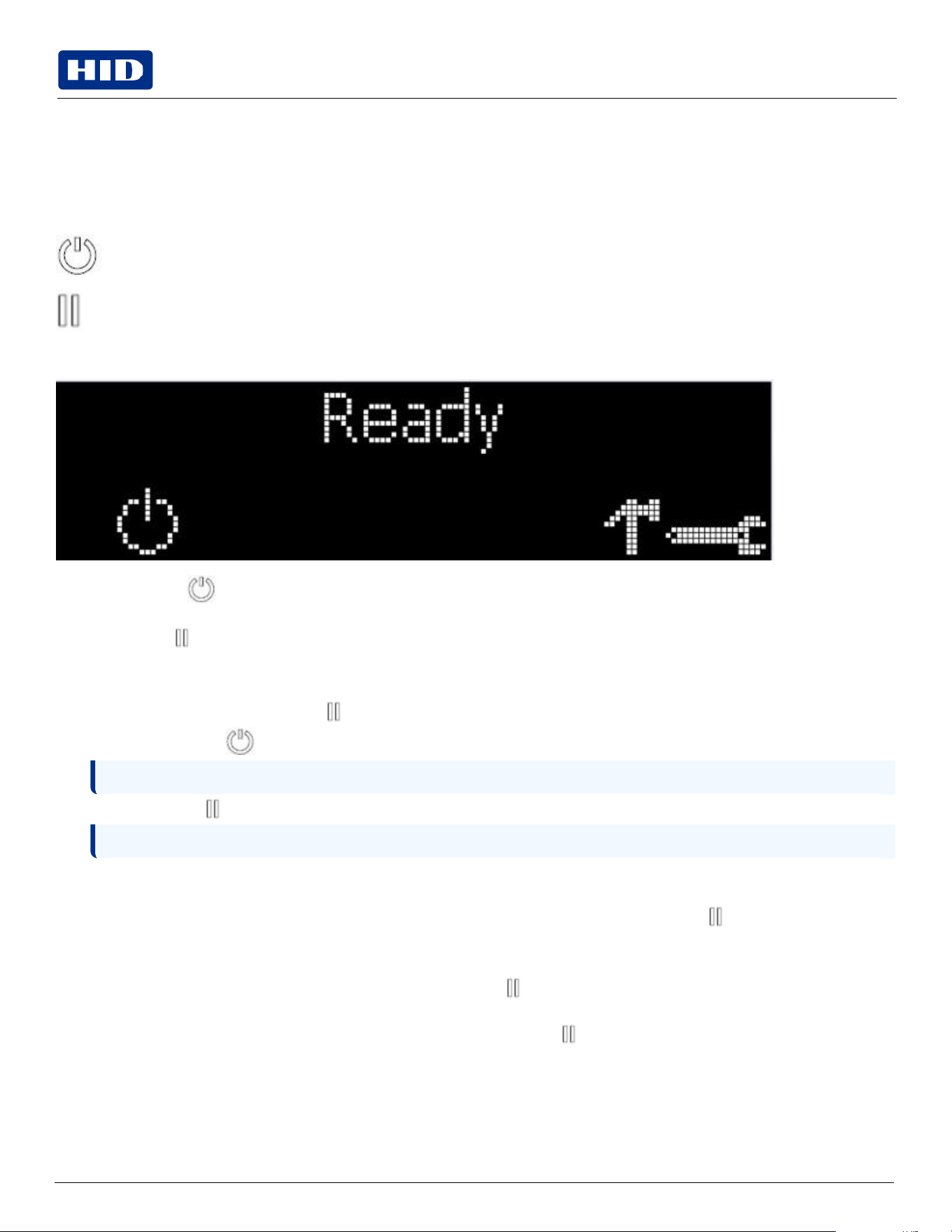
Public
Note:
The button illuminates as blue and retries the failed action.
5.2
Troubleshooting
5.2.1
Printer
Error
buttons
The DTC1250e and DTC1000Me use button messages rather than an LCD display message system. All printers have two
(2) buttons.
ON/OFF
Pause
The display message system appears as a graphical message, for example:
1.
The ON/OFF button is blue when the printer is ON. When the printer enters the Sleep mode, the button LED is
dimmed but still ON.
2.
The Pause button illuminates blue when the printer is capable of accepting a print job and is not in an error state.
This button LED will continue to stay on while the printer prints as long as there is no error.
This button LED will also be dimmed when the printer goes into Sleep mode.
3.
When an error occurs, the Pause button no longer illuminates blue but blinks red.
4.
Press the ON/OFF button when printer is in an error state to cause the action to be canceled.
5.
6.
When downloading an upgrade file, both buttons are blue and blink. If the unit is a DTC1250e, you are notified that
the upgrade is in process.
7.
If a language (other than English) is currently selected, you can press and hold the Pause button during the
power-up sequence to change the language back to English.
8.
When no printer display is available, press or hold the buttons to access some internal tests.
To print a card with the Printer Settings, press the Pause button and hold for 4+ seconds when the printer is
ready and idle.
To print the Alignment or the Self Test, press and hold the Pause button during the power-up sequence.
Note:
If no other error occurs, the Pause button illuminates as blue.
Press the Pause button when printer is in an error state to cause the printer to retry.
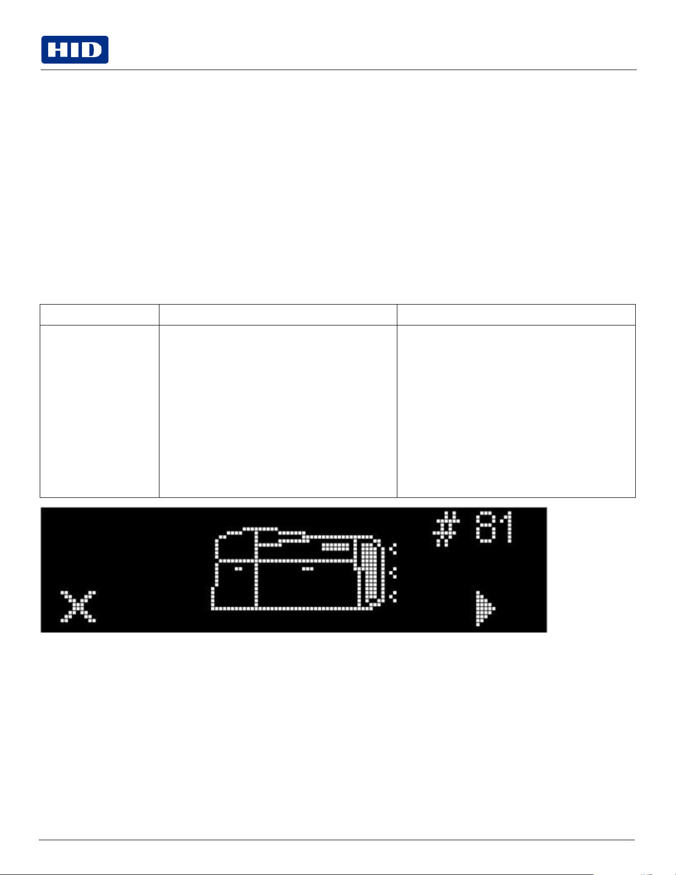
Public
5.2.2
Error
messages
This section provides the troubleshooting table for the error message (for DTC1250e and DTC1000Me). The DTC4250e
and DTCii Plus has a display that shows the printer error messages.
When an error occurs in the printer, the PC shows the error message on screen with solutions.
The display blinks in the location requiring attention. Locations can include the printer, input hopper, magnetic
encoder, flipper, card path, ribbon, and data/communication device error.
Each table uses a 3-column presentation to display a specific or printer error message, its cause and its solution.
This format allows the troubleshooter to identify the error and its cause, and then perform the procedure provided in
the solution column.
This standard mode of identifying the problem and its solution should provide an efficient method of troubleshooting
this printer.
If you encounter problems beyond the capabilities of this error message table, you should contact Technical Support.
Error
message
Cause
Solution
# 81
Unable
to
Feed
The printer is unable to feed a card from the input
card hopper.
Check the following, then press the Pause button to
continue.
Verify the card thickness setting is set to the
thickness of your cards.
Verify the cleaning roller is properly installed on
the ribbon cartridge.
Check for card slippage. If necessary, run the
printer cleaning routine.
Verify that your cards are within the accepted
card size range.
Verify the cards are not sticking together.
Public
5.2.3
Troubleshooting
with
the
Error
Message
table
Error
message
Cause
Solution
# 2 Head Move Error
The
print
head
lift
has
malfunctioned.
Reset
the
printer
and
try
again.
If this problem persists, call for technical assistance.
# 8 Head Sensor Error
The print head temperature sensor is not functioning
or is not connected properly.
Or,
the
print
head
is
not
cooling
properly.
Reset
the
printer
and
try
again.
If
the
problem
persists,
call
for
technical
assistance.
#
9
Reboot
Required
An unspecified system error has been detected by the
printer firmware.
Reset
the
printer
and
try
again.
If this problem persists, call for technical assistance.
#
25
Ribbon
not
Installed
No ribbon is installed in the printer.
Install a ribbon and retry.
# 30 Mag Verify Error
Magnetic
encoding
verification
has
failed.
Try encoding with a different card. Verify cards have
the magnetic stripe. Replace the magnetic encoding
module.
# 31 No Mag Module
The printer is not configured with the encoder data
type that you are trying to send.
Ensure that no encoding data is being sent with the
print job and reprint the card.
Install
a
magnetic
encoding
module.
# 38
# 39
# 40
EEPROM Corrupt
EEPROM Read Error
EEPROM is
restored
with factory
default
values.
If changes were made in the Advanced Settings tab in
the printer driver, click the Default button to reset
these numbers.
Reset the printer and try again. If this problem
persists, call for technical assistance.
# 44
Flipper Jam/ Home Error
A card has become jammed in the printer’s flipper
table.
The flipper failed to position properly while aligning a
card or flipping a card.
Clear any cards in the flipper table using the buttons
to move the card out. Resume printing.
The flipper table should be level when the printer is
powered up. If the flipper table is at an angle, open the
card output door and manually level it. Then cycle the
printer power to reset.
Reset the printer and retry. If problem persists call for
technical assistance.
# 45
No
Flip
Module
installed
Request to print on 2nd side of card, but no flipper is
installed.
If a flipper module is present, ensure that the Print
Both Sides option in the printer driver is set correctly.
Install
a
flipper
module.
# 64
# 65
# 66
Reboot
Required
Unspecified system error detected by the printer
firmware.
Reset
the
printer
and
try
again.
If this problem persists, call for technical assistance.
# 68 Card
in Printer
A card is jammed in the print station or card flipping
area of the Printer.
Clear the jam and press the Pause button.
Public
Error
message
Cause
Solution
# 70 Multiple
Feed
Multiple
cards
were
fed
into
the
printer.
Verify the card thickness is set to the thickness of
your cards, then press the Pause button.
Check for card slippage. If necessary, run the printer
cleaning routine. Verify the cleaning roller is properly
installed on the ribbon cartridge. Verify the cards are
not sticking together.
# 81 Unable to Feed
The printer is unable to feed a card from the input
card hopper.
Check the following, then press the Pause button to
continue. Verify the card thickness setting is set to
the thickness of your cards. Verify the cleaning roller
is properly installed on the ribbon cartridge. Check for
card slippage. If necessary, run the printer cleaning
routine.
Verify that your cards are within the perimeters
accepted card size range.
Verify the cards are not sticking together.
# 82 Mag Jam
A card
is jammed
magnetic
station
Clear any cards in the magnetic station using the
buttons to move the card out.
Press
the
Pause
button
to
continue.
#
91
Ribbon
Out
The print ribbon has run out.
Install a new ribbon.
Press the Pause button to continue or the ON/OFF
button to cancel.
# 93 Wrong Ribbon
The print ribbon installed in the printer does not
match the ribbon type selected in the printer driver.
Change either the installed print ribbon or the ribbon
type selected in the printer driver.
Press the Pause button to continue or the ON/OFF
button to cancel.
#
97
Ribbon
Search
Error
The ribbon is not able to find the next panel correctly.
Check for jams/breaks.
Recalibrate
the
ribbon
sensor.
If broken, repair by taping the ribbon back on to the
take- up core. Replace the ribbon.
Press the Pause button to continue or the ON/OFF
button to cancel.
#
99
Ribbon
Error
The
print
ribbon
has
either
broken
or
jammed.
If
jammed,
clear
the
jam.
If broken, repair by taping the ribbon back on to the
take-up core. Press the Pause button to continue or
the ON/OFF button to cancel.
# 100 Ribbon RFID Error
There is no ribbon or the ribbon tag information is
corrupted or incorrect.
Verify the printer driver settings for correct ribbon. Try
a new ribbon and continue.
Press the ON/OFF button
to cancel.
# 102
# 103
# 104
#3
Head
lift
Error
This is a problem with the print head Lift.
Reset
the
printer
and
try
again.
If this problem persists, call for technical assistance.
Public
Error
message
Cause
Solution
# 106 Job Data Error
The print data sent to the printer is corrupt or has
been interrupted.
Check
the
interface
cable.
Select the ON/OFF button to cancel this print job and
then resend the job.
#
107
Printing
Error
An error was detected during printing.
Reset
the
printer
and
try
again.
If this problem persists, call for technical assistance.
# 109
# 113
Ribbon
Release
Error
The printer cannot locate the next ribbon panel in
order to release the ribbon from the card.
Ensure that the ribbon is not stuck to the card.
Replace the ribbon.
Recalibrate
the
ribbon
sensor.
If the ribbon is broken, repair by taping the ribbon
back onto the take-up core and manually advance to
the next panel.
Press
the
Pause
button
to
continue.
# 110
Card
Jam/Align
error
A card is jammed in the print station or card flipping
area of the printer.
Clear the jam. Press the Pause button to continue.
# 111
Head
Loading
An unrecoverable error has occurred during printing.
Reset the printer and try again. If this problem
persists, call for technical assistance.
# 112
Card
Jam/Align
error
A card is jammed in the print station or card flipping
area of the Printer.
Clear the jam. Press the Pause button to continue.
# 128
# 170
Calibrate
Ribbon
The print ribbon sensor is out of calibration or has
failed.
Calibrate
the
ribbon
sensor.
Check for material blocking sensor and try again.
# 131
Flipper
Jam/Home
Error
A card has become jammed in the printer’s flipper
table.
The flipper failed to position properly while aligning a
card or flipping a card.
Clear any cards in the flipper table, using the buttons
to move the card out.
Resume
printing.
Reset the printer and retry. If problem persists call for
technical assistance.
# 136
Secure Guard Print
Disabled
Printing is disabled by SecureGuard until a password
is received.
Reset
the
printer
and
retry.
If
the
problem
persists,
call
for
technical
assistance.
# 139 Please Remove
Ribbon
Ribbon needs to be removed.
Reset
the
printer
and
retry.
If problem persists, call for technical assistance.
# 144
EEPROM Corrupt
EEPROM Read Error
EEPROM restored with factory default
values.
If changes were made in the Advanced Setting tab in
the printer driver, click the Default button to reset
these numbers.
Reset the printer and try again. If this problem
persists, call for technical assistance.
#202 Encoder not
installed
You are trying to send encoding data, but the printer is
not configured with this encoder type.
iCLASS,
Prox,
MIFARE,
SmartCard
Ensure that no encoding data is being sent with the
print job and reprint the card.
Install
an
encoding
module.
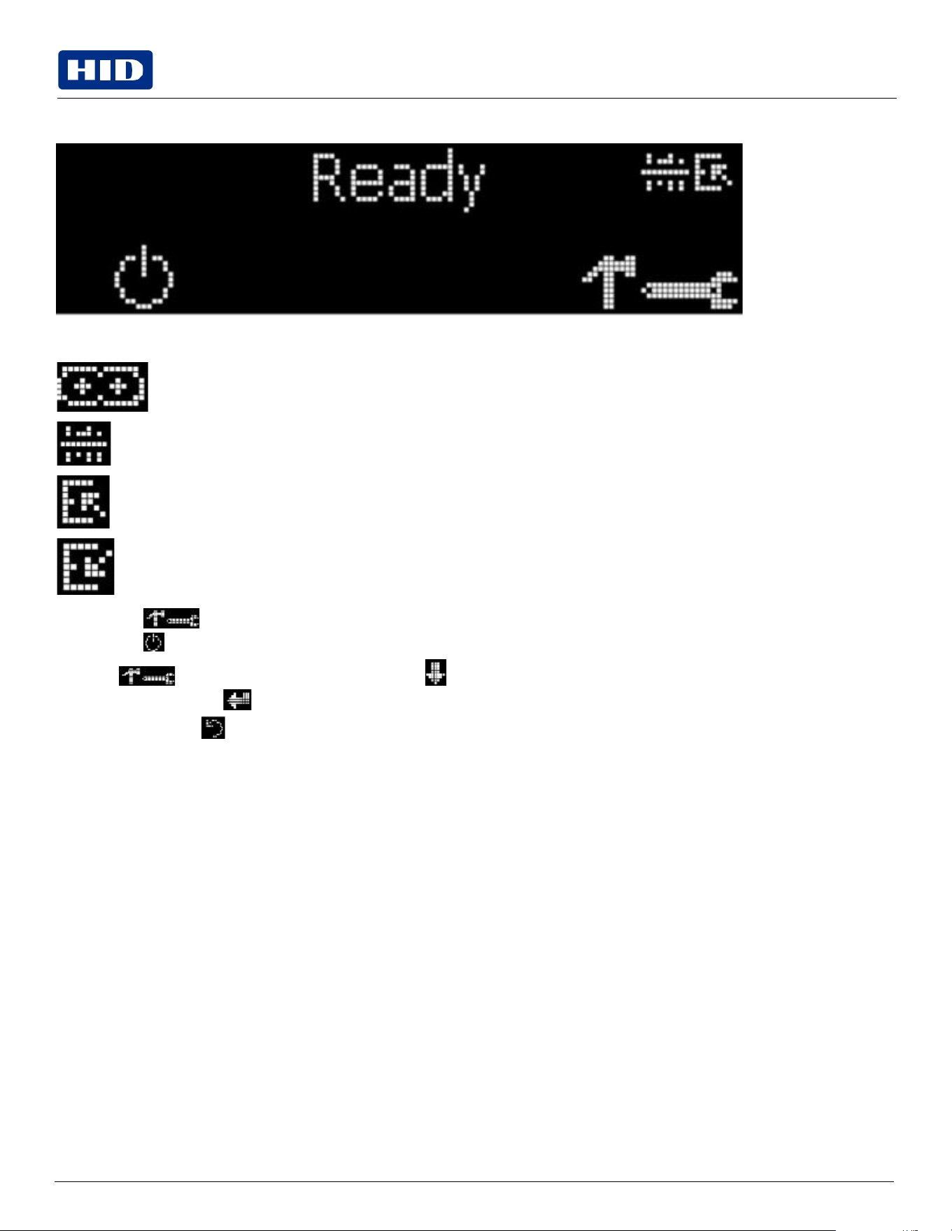
Public
5.2.4
Printer-specific
tools
(DTC1250e,
DTC4250e,
and
DTCii
Plus)
The status icons are as follows:
This icon indicates that the print ribbon supply is low and will require replacement soon. For the
DTC1250e, DTC4250e, and DTCii Plus models, the entire ribbon cartridge must be replaced.
This icon indicates that the printer needs to be cleaned.
This icon is only displayed for printers with an attached dual-input card hopper and indicates that the
top input hopper is currently selected.
This icon is only displayed for printers with an attached dual-input card hopper and indicates that the
bottom input hopper is currently selected.
Press the button to scroll through the details of the printer and perform the action.
Press the button to select the option.
When is selected, use the left down arrow to scroll through the Info, Test Prints, and Languages and Exit.
Use the corner arrow to run that option.
The curved arrow will return to the first screen.
Public
Additional
printer
specific
tools
Label
Description
INFO
Printer
Type
Firmware
Version
IP
Address
Flipper
Lamination
Magnetics
E-
Card
Password
Card
count
TEST
PRINTS
Color Photo: Select this to print a color card to test communication and integrity.
Alignment: Select this to print a card used to align the print image on the card.
Settings: Select this to print a card with the Advanced settings.
Resin: Select this to print a RESIN test card.
Rewritable: Select this to ERASE the Rewritable card.
Magnetic: Select this to test Magnetic encoding. (Hi-Co only)
Lamination:
Select
this
to
laminate
a
test
card.
Hopper
Select
Ability to select which hopper to feed cards from. Applies to dual hopper printers. Exception feeding for DTCii Plus only
Toolbox
Clean
Printer:
Select
this
to
run
the
clean
printer
routine.
Clean Laminator: Select this to run the clean laminator routine.
Calibrate Mag: Select this to calibrate the Magnetic Sensor
Calibrate Rib Sensor: Select this to calibrate the ribbon sensor.
Network: Select this to configure network options.
Language
Select this choice to change the printer displaye language.
Exit
Select
this
choice
to
exit
the
printer
tools
options.

Public
Section 06
Firmware
upgrades

Public
Powering
Trusted Identities
6.1
Upgrade
information
HID®
FARGO®
DTC™1250e,
DTC1000Me,
DTC4250e,
and
DTCii
Plus
Card
Printer
User
Guide
To upgrade the printer’s firmware, perform the following steps:
1.
Run the
FARGO Workbench Printer Utility
.
2.
If running FARGO Workbench Version 3 or greater:
a.
Select
the
Update Manager Workbench Utility
.
b.
Select the printer(s) to update.
c.
Click Select Firmware file… option to locate or enter this latest firmware file.
d.
Browse for the firmware file or enter the firmware file name and click Open.
e.
Click
Begin
Updating
Firmware
to
send
the
file
to
the
printer(s).
3.
If running a FARGO Workbench release prior to Version 3:
a.
Select the Application Menu at the upper left, and select Upgrade Firmware.
b.
Enter the firmware file name or click Browse to find and select this latest firmware file.
c.
Click OK to send the file to the printer(s).
4.
Restart the printer if it does not restart automatically.

Public
Section 07
Technical
support

Public
Powering
Trusted Identities
7.1
Introduction
HID®
FARGO®
DTC™1250e,
DTC1000Me,
DTC4250e,
and
DTCii
Plus
Card
Printer
User
Guide
This section provides you with an efficient, step-by-step procedure to be used when contacting HID Global Technical
Support, as needed, for this card printer.
Contact the HID Global Technical Support Group at: www.hidglobal.com/support.
Before contacting HID Global Technical Support:
Position a phone near the printer and computer so the Technician can help to troubleshoot the printer.
Have a self-test and a sample card ready when calling HID Global Technical Support.
7.2
Reading
the
serial
numbers
on
a
FARGO
printer
To determine when the card printer was manufactured, see the serial number (affixed to the card printer). With the
Example: Serial Number B2050028 (2012)
The first two digits in the serial number indicate the year the printer was built (B2 indicates the year 2012).
The third and fourth digits in the serial number indicate the week the printer was built (05 indicates week 5 of that
year).
The last four digits indicate the sequence number for the numeric order in which the printers were built.

Public
Appendix A
DTCii
Plus
Public
Note:
HID Global does not sell any type of locking device, but provides this feature for your added security.
Note: Push the lock end into the slot with adequate force to break the protective film.
A.1
Introduction
This section is specific to the DTCii Plus printer only.
Dimensions (H × W × D): 255.3 mm × 582.7 mm × 260.9 mm (10.05″ × 22.94″ × 10.27″) .
A.2
Locking
system
The DTCii Plus provides additional security with the inclusion of locks on the following components:
Card Input
Reject Hopper
Material Door
A set of two identical keys are provided that will unlock all sections of the printer. In the event that these keys are
misplaced, please contact HID Customer Services.
A.3
Accessory
procedures:
using
the
security
lock
slot
The DTCii Plus printer has a Security Lock Slot located in the back lip of the metal chassis to accommodate a standard
laptop security lock.
To prevent unauthorized removal of the DTCii Plus, attach an industry standard security cable to an immovable object
and then lock the cable to the Security Lock Slot.
The lock slot has a plastic covering that needs to be penetrated by the lock.
Follow the locking procedure recommended by the lock vendor.
Public
Revision
history
Date
Description
Revision
July
2025
Updated
technical
specifications.
1.7
January
2022
Updates printer setting information in Section 4.
1.5
October
2019
Updates to include additional DTCii model information.
1.4
September
2018
Minor
updates.
1.3
December
2016
Updates to include DTCii model information.
1.2