0361526D© 2023 Suncast Corporation, Batavia, IL
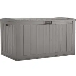
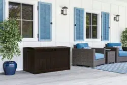
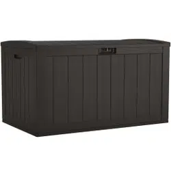
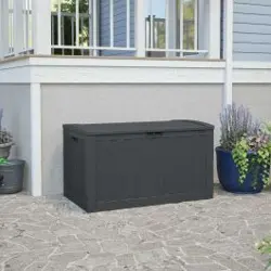
Blow Molded Deck Box, 134gal
ASSEMBLY INSTRUCTIONS
Coffre de terrasse moulé par soufage,
507 litres (134 gal)
INSTRUCTIONS D’ASSEMBLAGE
Arcón de resina moldeada para terraza,
134 gal.(507litros)
INSTRUCCIONES DE ARMADO
S
e
e
W
h
a
t
S
u
n
c
a
s
t
i
s
D
o
i
n
g
t
o
A
c
h
i
e
v
e
a
B
r
i
g
h
t
e
r
,
M
o
r
e
S
u
s
t
a
i
n
a
b
l
e
F
u
t
u
r
e
English .........................3
Français ......................18
Español ......................33

Register your product for Limited Warranty!
Must register product within 90 days of purchase for limited warranty
Enregistrez votre produit au programme de garantie limitée
Vous devez enregistrer votre produit au programme de garantie limitée dans les 90 jours suivant votre achat.
iRegistre su producto para obtener una garantía limitada!
Debe registrar el producto dentro de los 90 días posteriores a la compra para obtener una garantía limitada
Scan for updated Limited Warranty
Scanner pour obtenir la grantie limitée à jour
Escanear para obtener garantía limitada actualizada
www.suncast.com/warranty or call US 1 (800) 846-2345
www.suncast.com/warranty ou appelez-nous 1 (800) 846-2345
www.suncast.com/warranty o llamenos 1 (800) 846-2345
Have Questions?
We are here to help. Check out our resource library along with helpful tips,
videos and FAQ’s at https://support.suncast.com
You may call the Customer Care Center directly at: 1 (800) 846-2345 or write
Suncast Corporation, Customer Care Center, 701 N. Kirk Road, Batavia, IL 60510 (USA)
Des questions?
Nous pouvons vous aider. Consultez notre bibliothèque de ressources où vous trouverez des conseils utiles,
des vidéos et une FAQ sur https://support.suncast.com.
Vous pouvez communiquer directement avec le centre d’appels au: 1-800-846-2345 ou écrire à
Suncast Corporation, Customer Care Center, 701 N. Kirk Road, Batavia, IL 60510 (États-Unis)
¿Alguna pregunta?
Estamos aquí para ayudarle. Consulte nuestra biblioteca de recursos junto con sugerencias útiles,
videos y preguntas frecuentes en https://support.suncast.com.
Puede llamar al Centro de atención directamente al: 1 (800) 846-2345 o escribir a
Suncast Corporation, Customer Care Center, 701 N. Kirk Road, Batavia, IL 60510 (EE.UU.)
To purchase Suncast replacement parts and learn about other Suncast products visit us online or call.
Pour acheter des pièces de rechange Suncast et pour plus d’informations sur d’autres articles Suncast, rendez-vous
sur notre site Internet ou appelez-nous.
Para comprar piezas de repuesto Suncast y obtener más información acerca de otros productos Suncast, visítenos
en línea o llámenos por teléfono.
www.suncast.com
1-800-846-2345 or 1-630-381-6309.
1-800-846-2345 ou le 1-630-381-6309.
1-800-846-2345 o al 1-630-381-6309.

3
Cleaning and Maintenance
Part How to clean
Deck Box
To maintain the look of your product, we recommend
cleaning it each year with mild soap and water. DO NOT
use bleach, ammonia, or other caustic cleaners, and DO
NOT use stiff bristle brushes. Failure to perform annual
cleaning could result in permanent staining of the plastic.
This is not a manufacturing defect and is not covered
under warranty.
Safety and Compliance
• This item uses self-tapping screws in some areas. There are no pre-drilled
holes in the plastic. Use force when starting to drive the screw. Once the
screw pierces the plastic it will drive easier.
• Not intended for storage of flammable or caustic chemicals.
• Not intended for usage by children.
• This is not a toy box.
• To avoid risk of suffocation, do not allow children to play inside container.
• This product may become susceptible to impact damage in freezing
temperatures.
• DO NOT store near excessive heat.
• Exercise caution when moving fully loaded product. This product is not
intended for transporting heavy objects. Use as a stationary storage
device only.
• DO NOT stand on top.
• DO NOT store items on top.
4
Welcome Guide · English
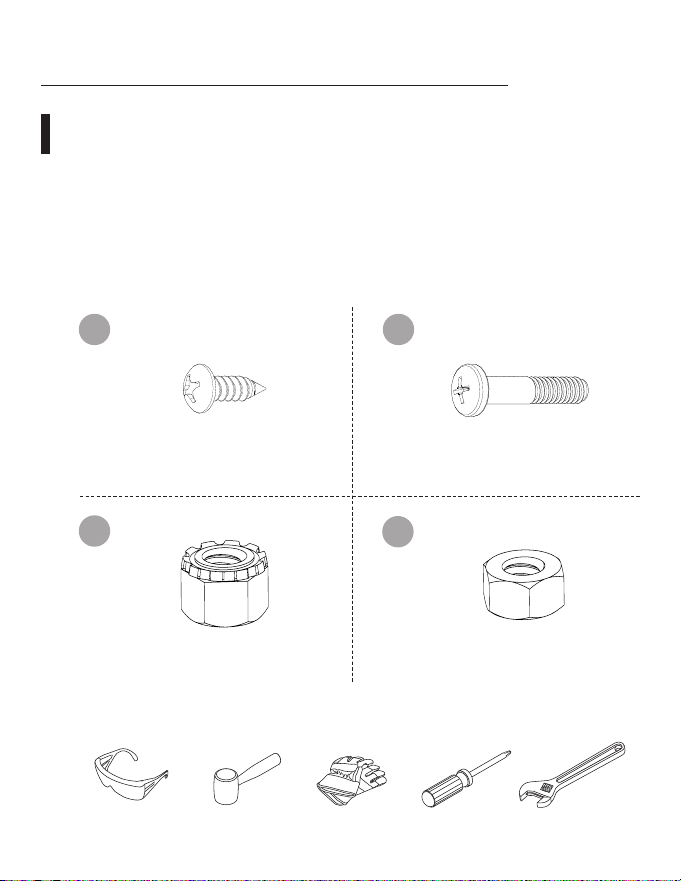
Contents:
Before getting started, ensure the package contains the
following components:
Parts shown may vary in style or color from the actual product.
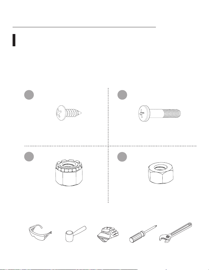
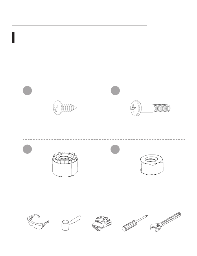
G
I
H
x23
x4
x4
Hardware
Tools Required
x4
J
5
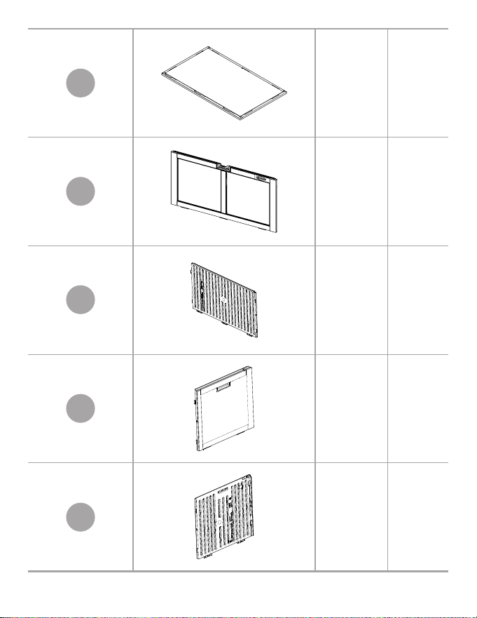
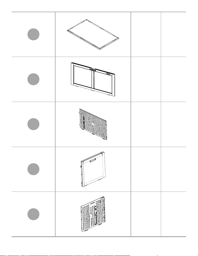
A Bottom x1
B
Front
Panel
x1
C
Rear
Panel
x1
D
Right
Panel
x1
E
Left
Panel
x1
6
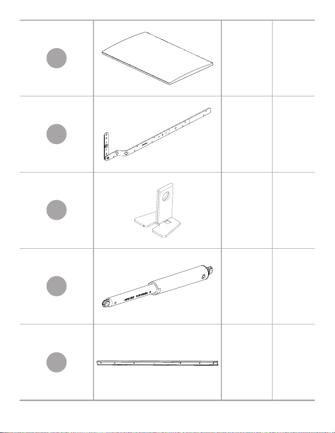
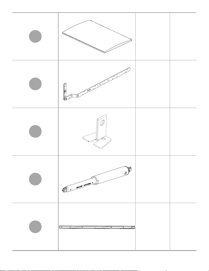
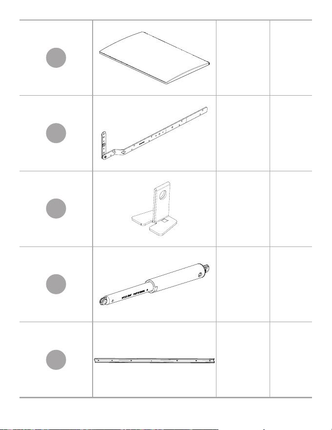
F Lid x1
K Hinge x2
L
Locking
Hasp
x1
M Shock x2
N S-Rail x1
7
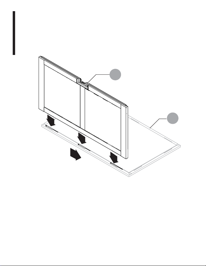
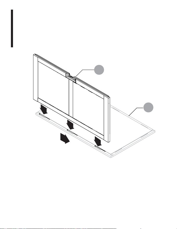
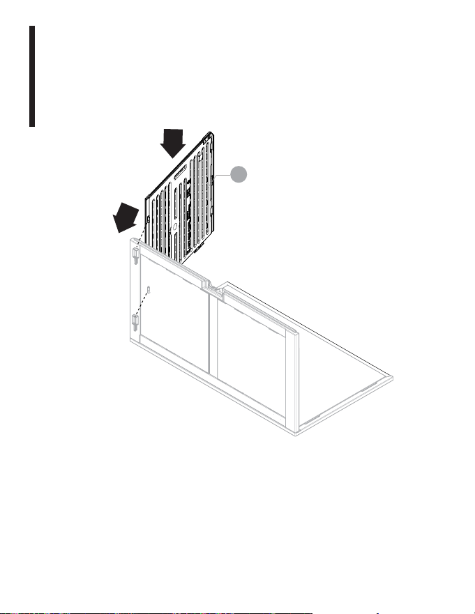
Assembly Instructions
Step 1:
Inserting Front Panel
Place floor smooth side facing up. Lower front panel (B) down
into slots bottom (A). While standing on bottom push down and
to the left to snap into place.
1
1
1
2
B
A

8
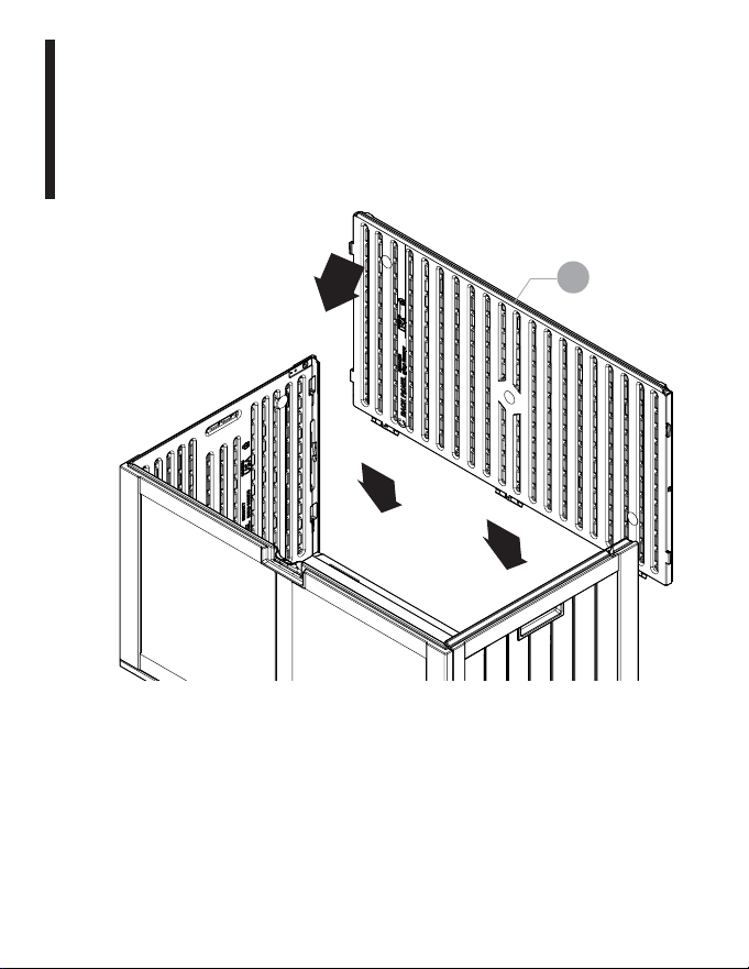
Assembly Instructions
Step 2:
Inserting Left Panel
Insert tabs on left side panel (E) into slots on front panel. Push
down until you hear a snap. Repeat with the other side panel.
1
2
E
9
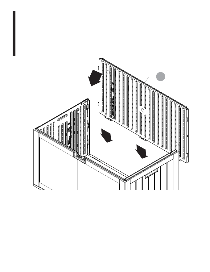
Assembly Instructions
Step 3:
Inserting Back Panel
Insert tabs on rear panel into slots on left and right panels. Lower
back panel (C) down into slots on floor. Push down hard to snap
into place.
2
1
2
C
10
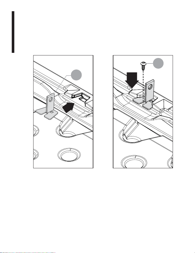
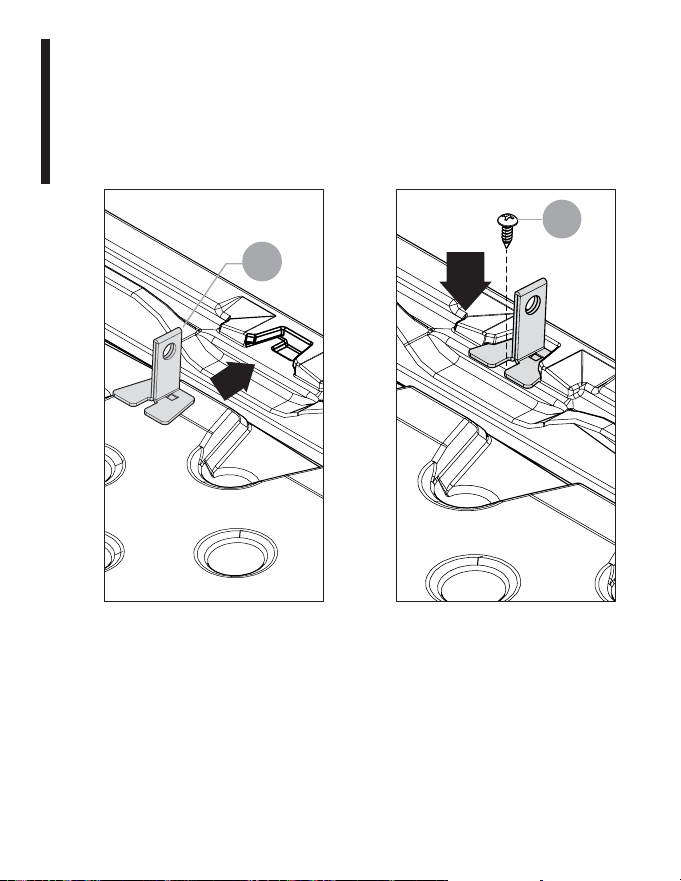
Assembly Instructions
Step 4:
Inserting Locking Hasp
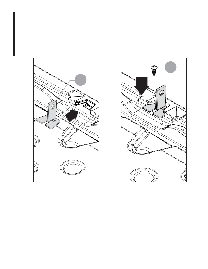
Insert locking hasp (L) into slot on lid and push in until you hear
a snap. Attach using screw (G).
1
L
2
G
11
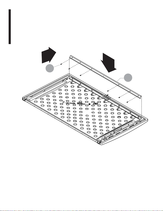
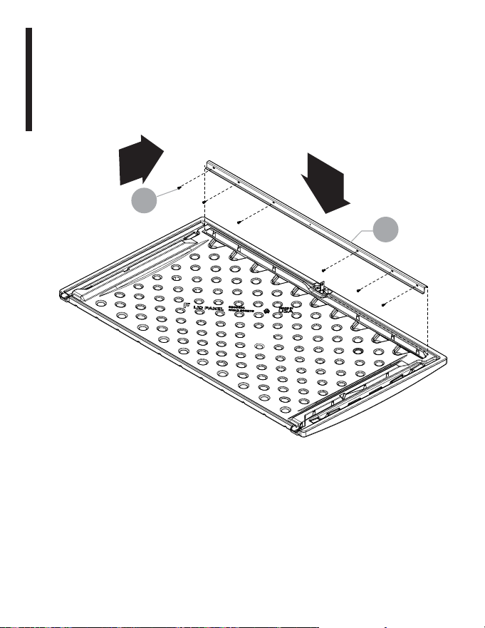
Assembly Instructions
Step 5:
Attach S-Rail
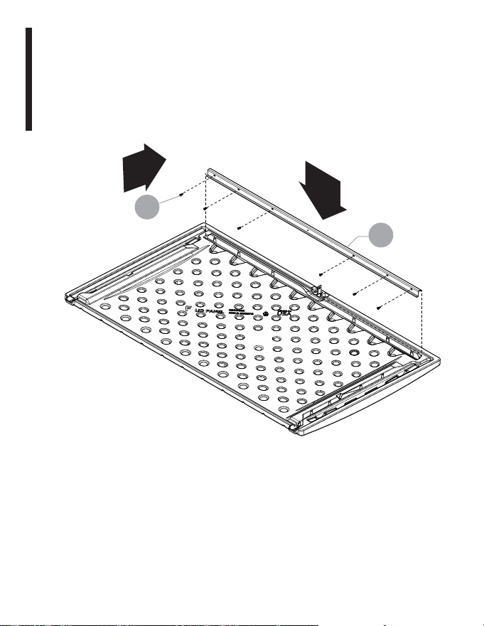
Attach support bracket (N) to lid through pre-drilled holes, using
six screws (G). There are no pre-drilled holes on the lid. Use force
when starting to drive screws. Once the screw pierces the plastic
it will drive easier. Do not use center hole on (N).
1
2
x6
G
N
12
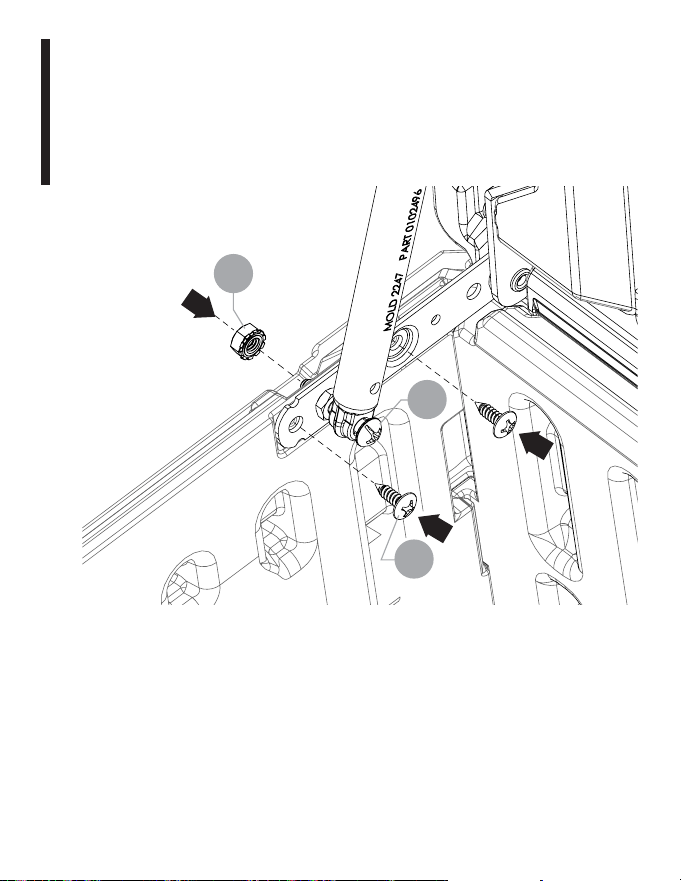
Assembly Instructions
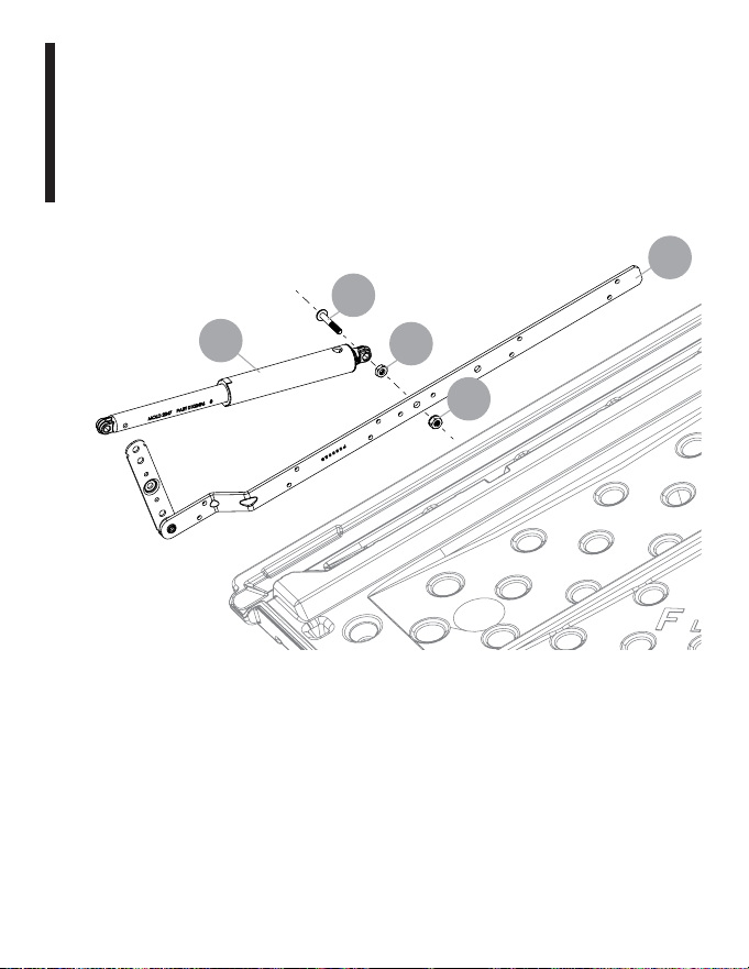
Step 6:
Attaching top of Shock to Hinge
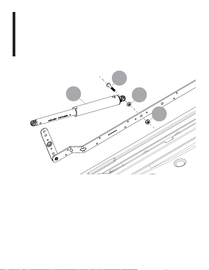
Insert bolt (H) into hole in top of Shock (M). Thread nut (J) onto
bolt (H) and tighten. Insert bolt (H) into hinge (K). Use a wrench
to tighten nut (I) onto bolt (H)
Repeat with hinge on other side.
H
J
I
M
K
13
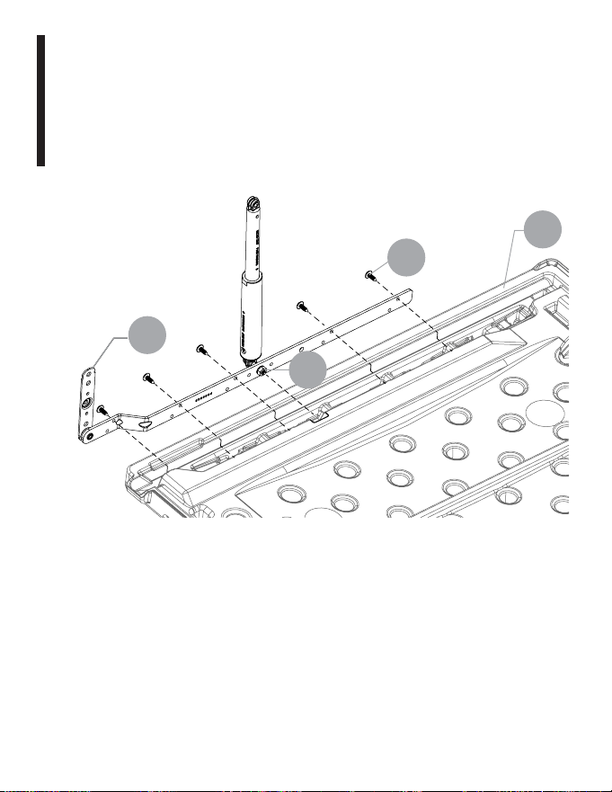
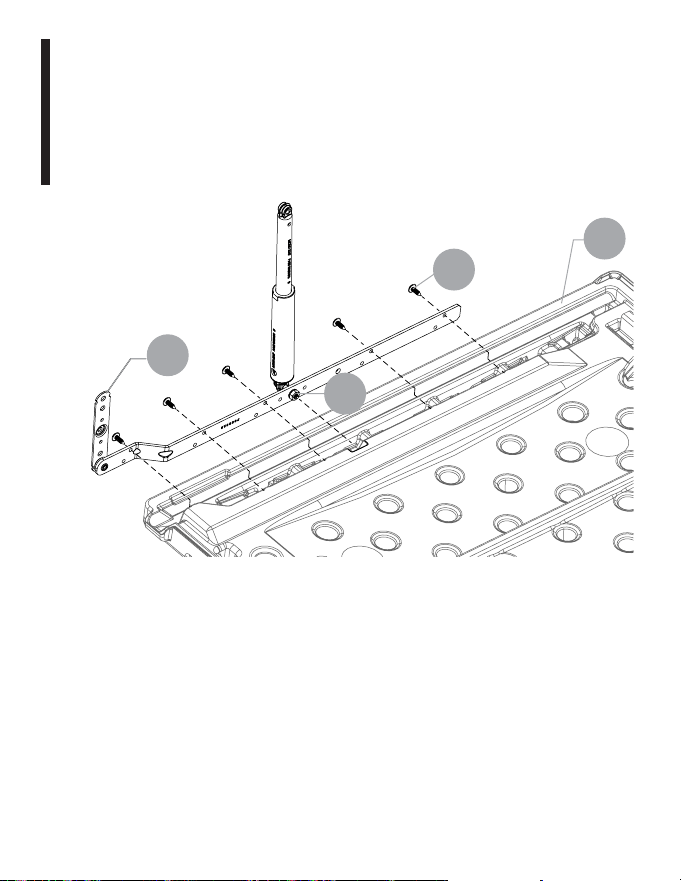
Lower hinge (K) to lid (F). Nut (I) should nest into pocket on lid.
Attach hinge to lid by using five screws (G). There are no
pre-drilled holes on the lid. Use force when starting to drive
self-tapping screws. Once the screw pierces the plastic it will
drive easier.
Repeat with hinge on other side.
F
K
G
x5
I
Assembly Instructions
Step 7:
Attach Hinge to Lid
14
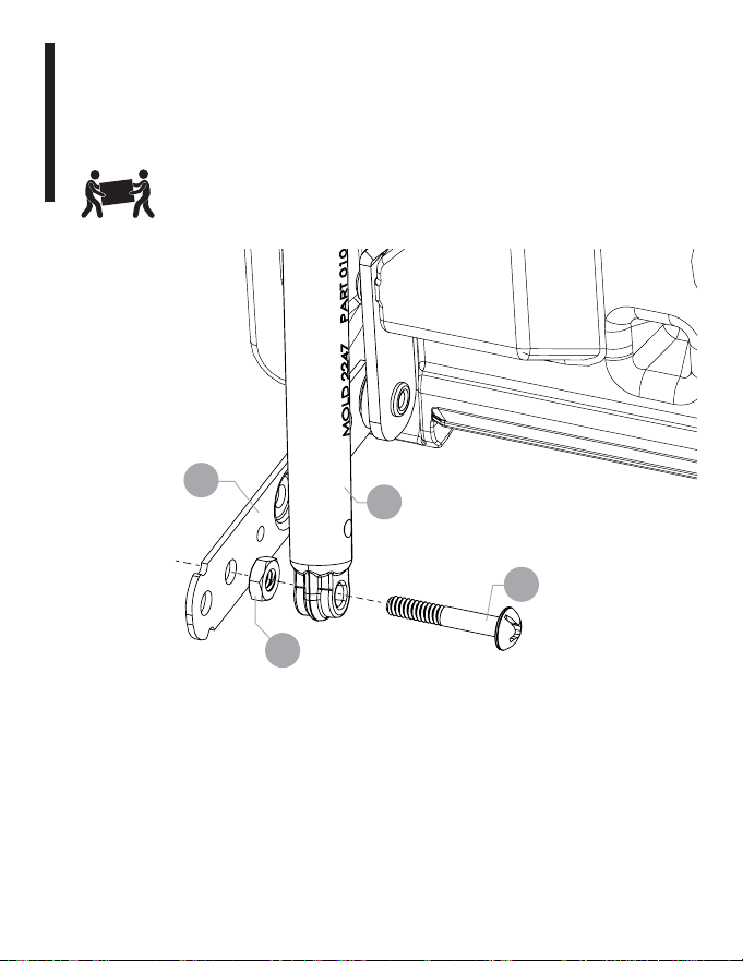
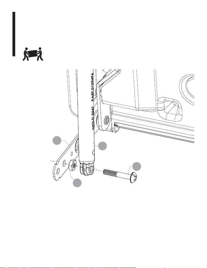
Assembly Instructions
Step 8:
Attach Shock to Lower Hinge
Insert bolt (H) into Shock (M) bottom. Thread nut (J) onto bolt (H)
and tighten. Insert Bolt (H) into lower hinge (K).
K
M
H
J

15
Assembly Instructions
Step 9:
Lower Lid to Deck Box
Lower the lid (F) onto base, inserting two bolts (H) into sides.
F
F
E
16
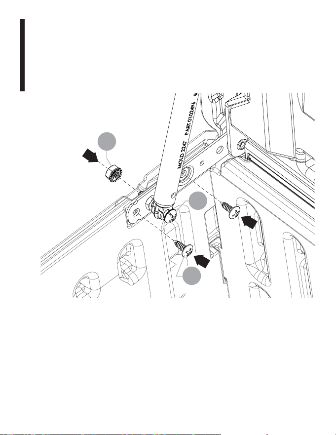
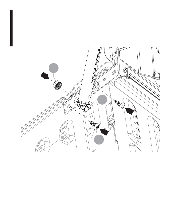
Assembly Instructions
Step 10:
Attaching Lid and Base
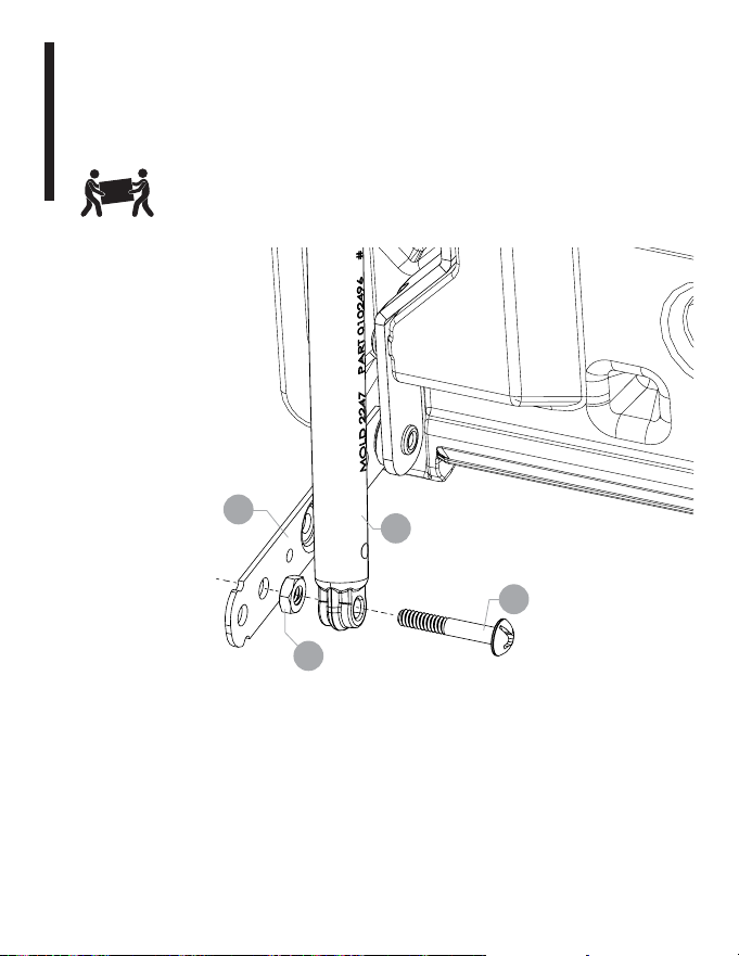
Use Nut (I) to secure the bolt (H) through the lower hinge and
the side panel. Tighten with wrench. Add screws (G) to finish
fastening the lower hinge to the side panel. Repeat for the
other side.
G
H
1
2
2
I
x2

17
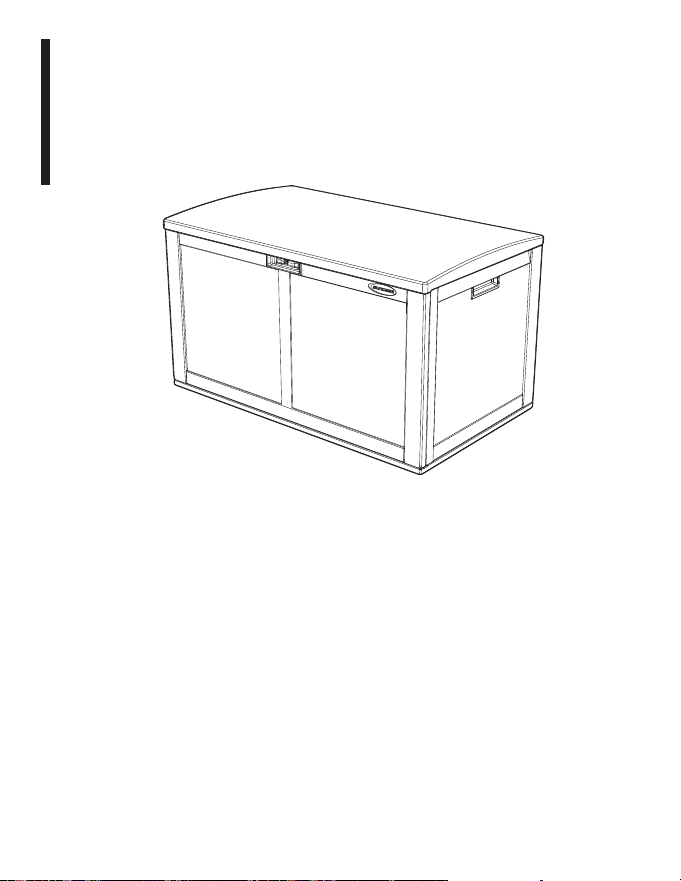
Assembly Instructions
Complete
This is your completed deck box.

18
Nettoyage et entretien
Pièce Nettoyage
Coffre de
terrasse
Pour préserver l’apparence de votre article, nous vous
recommandons de le nettoyer une fois par an avec de
l’eau et un détergent doux. NE PAS utiliser d’eau de
Javel, de l’ammoniaque ou tout autre produit nettoyant
caustique. NE PAS utiliser des brosses à poils durs. Le
plastique risque d’être décoloré de manière irréversible
si vous n’effectuez pas ce nettoyage annuel. Ceci ne
représente pas un défaut de fabrication et n’est pas
couvert par la garantie.
Sécurité et conformité
• Cet article utilise des vis autotaraudeuses pour le montage de certaines
pièces. Il n’y a pas de trous pré-percés dans le plastique. Veillez à bien
pousser fort sur la vis quand vous commencer à la visser. Une fois que la
vis aura percé le plastique, le vissage sera plus facile.
• Non prévu pour le stockage de produits chimiques inflammables ou
corrosifs.
• Non prévu pour une utilisation par des enfants.
• Ceci n’est pas un coffre à jouets.
• Pour éviter tout risque d’étouffement, ne laissez jamais des enfants jouer
dans le coffre.
• Le gel est susceptible d’endommager le coffre.
• NE PAS entreposer près d’une source de chaleur excessive.
• Faire preuve de prudence quand vous déplacez le coffre plein. Ce coffre
n’est pas destiné au transport d’objets lourds. Utiliser uniquement en tant
qu’unité de stockage fixe.
• NE PAS se tenir debout sur le coffre.
• NE PAS stocker des articles sur le coffre.
19
Guide d’accueil · Français
Contenu :
Avant de commencer, vérifier que le conditionnement contient
bien les composants suivants. Il se peut que le style ou la
couleur des pièces illustrées diffèrent de ceux du produit réel.
G
I
H
x23
x4
x4
Quincaillerie
Outil requis
x4
J
20
A Base x1
B
Panneau
Avant
x1
C
Panneau
Arrière
x1
D
Panneau
Latéral
Droit
x1
E
Panneau
Latéral
Gauche
x1
21
F
Couvercle
x1
K
Charnière
x2
L
Verrouillage
x1
M
L’amortis-
seur
x2
N
Support
x1
22
Instructions d’assemblage
Étape 1 :
Insertion du panneau avant
Placer la base sur le sol, côté lisse orienté vers le haut. Insérer les
languettes du panneau avant (B) dans les encoches de la base (A).
En vous tenant debout sur la base, pousser sur le panneau avant
vers le bas et vers la gauche pour l’enclencher.
1
1
1
2
B
A

23
Instructions d’assemblage
Étape 2 :
Insertion du panneau gauche
Insérez les languettes du panneau latéral gauche (E) dans
les fentes du panneau avant. Appuyez jusqu’à ce que vous
entendiez un claquement. Répétez l’opération avec l’autre
panneau latéral.
1
2
E

24
Instructions d’assemblage
Étape 3 :
Insertion du panneau arrière
Insérez les languettes du panneau arrière dans les fentes des
panneaux gauche et droit. Abaissez le panneau arrière (C) dans
les fentes du sol. Appuyez fort pour le mettre en place.
2
1
2
C
25
Instructions d’assemblage
Étape 4 :
Insertion du système de verrouillage
Insérer le système de verrouillage (L) dans l’emplacement prévu
dans le couvercle et pousser jusqu’à ce que vous entendiez un
déclic. Fixer avec la vis (G).
1
L
2
G
26
Instructions d’assemblage
Étape 5 :
Mise en place du support en « S »
Fixer le support (N) au couvercle par les trous pré-percés, avec
six vis (G). Il n’y a pas de trous pré-percés dans le couvercle.
Veillez à bien pousser fort sur les vis quand vous commencer à
les visser. Une fois que la vis aura percé le plastique, le vissage
sera plus facile. Ne pas utiliser le trou central sur (N).
1
2
x6
G
N
27
Instructions d’assemblage
Étape 6 :
Fixation du dessus de l’amortisseur à la charnière
Insérez le boulon (H) dans le trou en haut de l’amortisseur (M).
Vissez l’écrou (J) sur le boulon (H) et serrez. Insérez le boulon (H)
dans la charnière (K). Utilisez une clé pour serrer l’écrou (I) sur le
boulon (H). Répétez avec la charnière de l’autre côté.
H
J
I
M
K

28
Abaissez la charnière (K) sur le couvercle (F). La noix (I) doit
être insérée dans la poche du couvercle. Fixez la charnière au
couvercle à l’aide de cinq vis (G). Il n’y a pas de trous pré-percés
sur le couvercle. Utilisez la force lorsque vous commencez à
enfoncer des vis auto-taraudeuses. Une fois que la vis a percé le
plastique, la conduite sera plus facile. Répétez avec la charnière
de l’autre côté.
Répéter l’opération pour la charnière sur l’autre côté.
F
K
G
x5
I
Instructions d’assemblage
Étape 7 :
Attacher la charnière au couvercle
29
Instructions d’assemblage
Étape 8 :
Fixer l’amortisseur à la charnière inférieure
Insérez le boulon (H) dans le bas de l’amortisseur (M). Vissez
l’écrou (J) sur le boulon (H) et serrez. Insérez le boulon (H) dans
la charnière inférieure (K).
K
M
H
J

30
Instructions d’assemblage
Étape 9 :
Couvercle inférieur à la caisse
Abaissez le couvercle (F) sur la base en insérant deux boulons
(H) dans les côtés.
F
F
E
31
Instructions d’assemblage
Étape 10 :
Fixation du couvercle et de la base
Utilisez l’écrou (I) pour fixer le boulon (H) à travers la charnière
inférieure et le panneau latéral. Serrer avec une clé. Ajoutez
des vis (G) pour terminer la fixation de la charnière inférieure
au panneau latéral. Répétez pour l’autre côté.
G
H
1
2
2
I
x2
32
Instructions d’assemblage
Assemblage terminé
Voici le coffre assemblé prêt au service.

33
Limpieza y mantenimiento
Pieza Cómo limpiar
Arcón
Para mantener la buena apariencia del producto,
recomendamos limpiarlo anualmente con agua y jabón
suave. NO use lejía, amoníaco ni otros limpiadores
cáusticos, y NO use cepillos de cerdas duras. El no
llevar a cabo una limpieza anual puede causar manchas
permanentes en el plástico. Ello no es un defecto de
fabricación y no está cubierto por la garantía.
Seguridad y cumplimiento de normas
• Este artículo utiliza tornillos autorroscantes en algunos lugares. No hay
agujeros previamente taladrados en el plástico el tornillo. Una vez que el
tornillo perfora el plástico entrará con más facilidad.
• No está diseñado para almacenar productos químicos inflamables o
cáusticos.
• No está diseñado para que lo usen niños.
• No es una caja de juguetes.
• Para evitar el riesgo de asfixia, no permita que los niños jueguen dentro
del contenedor.
• Este producto puede sufrir daño por impacto a temperaturas de
congelación.
• NO lo almacene cerca de una fuente de calor excesivo.
• Tenga cuidado al mover el arcón cuando esté completamente lleno. Este
producto no está fabricado para transportar objetos pesados. Úselo como
lugar de almacenamiento estacionario solamente.
• NO se pare encima del arcón.
• NO almacene objetos encima del arcón.
34
Guía de inicio - Español
Contenido:
Antes de empezar, asegúrese de que el paquete contenga los
componentes siguientes. Las piezas que se muestran puedan
variar en estilo o color con respecto al producto real.
G
I
H
x23
x4
x4
Tornillería
Herramientas necesarias
x4
J

35
A Inferiores x1
B
Panel
Frontal
x1
C
Panel
Posterior
x1
D
Panel
Lateral
Derecho
x1
E
Panel
Lateral
Izquierdo
x1
36
F Tapa x1
K Bisagra x2
L
Aldaba de
Seguridad
x1
M Choque x2
N Soporte x1

37
Instrucciones de armado
Paso 1:
Insertar el panel frontal
Coloque sobre el piso con el lado liso hacia arriba. Descienda el
panel frontal (B) dentro de las ranuras inferiores (A). Parado sobre
la parte inferior, empuje hacia abajo y hacia la izquierda para que
encaje en su lugar.
1
1
1
2
B
A
38
Instrucciones de armado
Paso 2:
Insertar el panel izquierdo
Inserte las lengüetas en el panel lateral izquierdo (E) en las
ranuras del panel frontal. Empuje hacia abajo hasta que
escuche un chasquido. Repita con el otro panel lateral.
1
2
E
39
Instrucciones de armado
Paso 3:
Insertar el panel izquierdo
Inserte las lengüetas en el panel posterior en las ranuras de los
paneles izquierdo y derecho. Baje el panel posterior (C) hacia
abajo en las ranuras del piso. Empuje hacia abajo con fuerza
para que encaje en su lugar.
2
1
2
C
40
Instrucciones de armado
Paso 4:
Insertar la aldaba de seguridad
Inserte la aldaba de seguridad (L) dentro de la ranura de la tapa
y presione hasta que escuche un chasquido. Acople con un
tornillo (G).
1
L
2
G
41
Instrucciones de armado
Paso 5:
Instalar el soporte en forma de “S”
Acople el soporte (N) a la tapa con seis tornillos (G) a través
de los agujeros previamente taladrados. No hay agujeros
previamente taladrados en la tapa. Use fuerza al empezar a
colocar los tornillos. Una vez que el tornillo perfore el plástico
entrará con más facilidad. No use el agujero central del
soporte (N).
1
2
x6
G
N

42
Instrucciones de armado
Paso 6:
Fijación de la parte superior del choque a la bisagra
Inserte el perno (H) en el orificio en la parte superior del Choque
(M). Enrosque la tuerca (J) en el perno (H) y apriete. Inserte el
perno (H) en la bisagra (K). Use una llave para apretar la tuerca (I)
en el perno (H) Repita con la bisagra del otro lado.
H
J
I
M
K
43
Baje la bisagra (K) a la tapa (F). La tuerca (I) debe encajar en el
bolsillo de la tapa. Fije la bisagra a la tapa con cinco tornillos (G).
No hay agujeros pretaladrados en la tapa. Use la fuerza
cuando comience a apretar tornillos autorroscantes. Una vez
que el tornillo perfora el plástico, se conducirá más fácilmente.
Repita con la bisagra del otro lado.
F
K
G
x5
I
Instrucciones de armado
Paso 7:
Fije la bisagra a la tapa
44
Instrucciones de armado
Paso 8:
Coloque el amortiguador en la bisagra inferior
Inserte el perno (H) en la parte inferior del Amortiguador (M).
Enrosque la tuerca (J) en el perno (H) y apriete. Inserte el
Perno (H) en la bisagra inferior (K).
K
M
H
J

45
Instrucciones de armado
Paso 9:
Tapa inferior a caja de cubierta
Baje la tapa (F) sobre la base, insertando dos pernos (H) en
los lados.
F
F
E
46
Instrucciones de armado
Paso 10:
Colocación de la tapa y la base
Use la tuerca (I) para asegurar el perno (H) a través de la bisagra
inferior y el panel lateral. Apriete con una llave inglesa. Agregue
tornillos (G) para terminar de fijar la bisagra inferior al panel
lateral. Repite por el otro lado.
G
H
1
2
2
I
x2

47
Instrucciones de armado
Completo
Este es el arcón completamente armado.