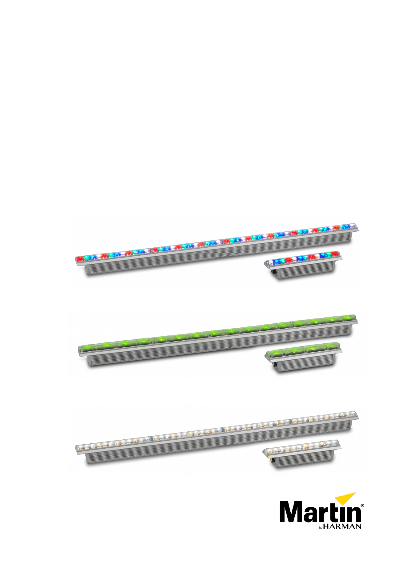
Exterior Linear Series
Exterior Linear Cove
Exterior Linear Graze
RGBW – QUAD – CTC
User manual
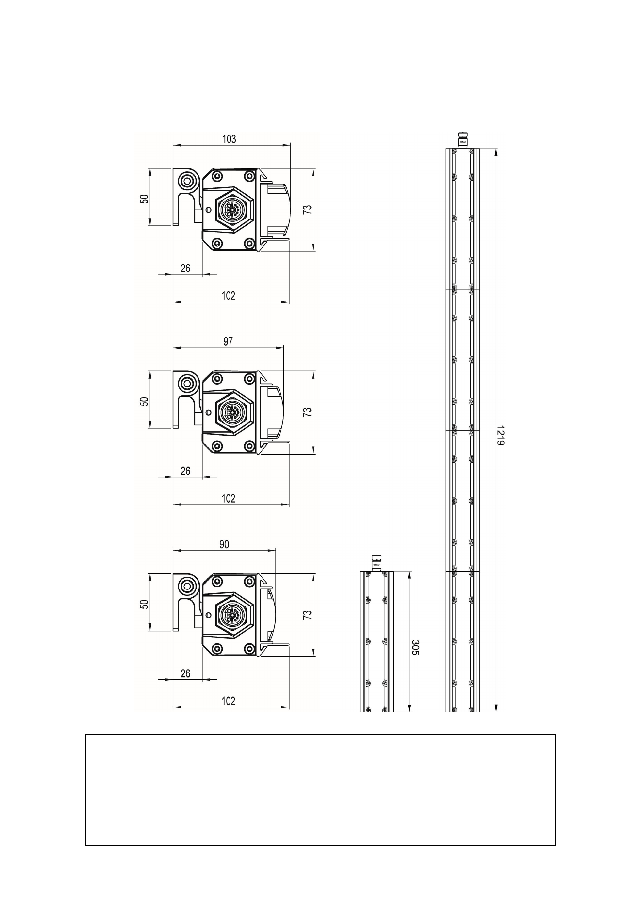
Dimensions
©2016-2021 HARMAN PROFESSIONAL DENMARK ApS. All rights reserved. Features, specifications and appearance
are subject to change without notice. HARMAN PROFESSIONAL DENMARK ApS and all affiliated companies disclaim
liability for any injury, damage, direct or indirect loss, consequential or economic loss or any other loss occasioned by
the use of, inability to use or reliance on the information contained in this document. Martin is a registered trademark of
HARMAN PROFESSIONAL DENMARK ApS registered in the United States and/or other countries.
HARMAN PROFESSIONAL DENMARK ApS, Olof Palmes Allé 44, 8200 Aarhus N, Denmark
HARMAN PROFESSIONAL SOLUTIONS U.S., 8500 Balboa Blvd., Northridge CA 91329, USA
www.martin.com
Exterior Linear Series User Manual Revision G
Cove 300/310/320/1200/1210/1220
Graze 300/320/1200/1220
Graze & Cove
300/310/320
Graze 310/1210
Graze & Cove 1200/1210/1220

Table of contents
Dimensions .............................................................................................................. 2
Safety information .................................................................................................... 4
Introduction .............................................................................................................. 7
Features ............................................................................................................. 7
Before using the product for the first time ........................................................... 7
Quad fixtures LED upgrade from 2022 ............................................................... 7
Fixture overview ....................................................................................................... 8
Physical installation .................................................................................................. 9
Fixture location ................................................................................................... 9
Mounting the fixture ............................................................................................ 9
Installing a Glare Shield .................................................................................... 11
Installing a Louvre (QUAD models) .................................................................. 11
AC power and data connection .............................................................................. 12
Power requirements ......................................................................................... 12
Data network requirements .............................................................................. 14
Connecting power and data .............................................................................. 15
Setup ...................................................................................................................... 16
RDM ................................................................................................................. 16
Step one: scanning for devices on the data link ............................................... 16
Setting up DMX behavior .................................................................................. 16
Temperature, current draw and refresh rate status .......................................... 17
Overall fixture status ......................................................................................... 17
RDM ................................................................................................................. 18
Maintenance .......................................................................................................... 19
Running test sequences ................................................................................... 19
Managing humidity ........................................................................................... 20
Cleaning ........................................................................................................... 21
DMX protocol ......................................................................................................... 22
Exterior Linear Series 300/310 & 1200/1210 RGBW/QUAD models ................ 22
Exterior Linear Series 320 & 1220 color temperature control (CTC) models .... 22
Matching color in older and newer QUAD fixtures ............................................ 23
Specifications ......................................................................................................... 24
4 Exterior Linear Series User Manual
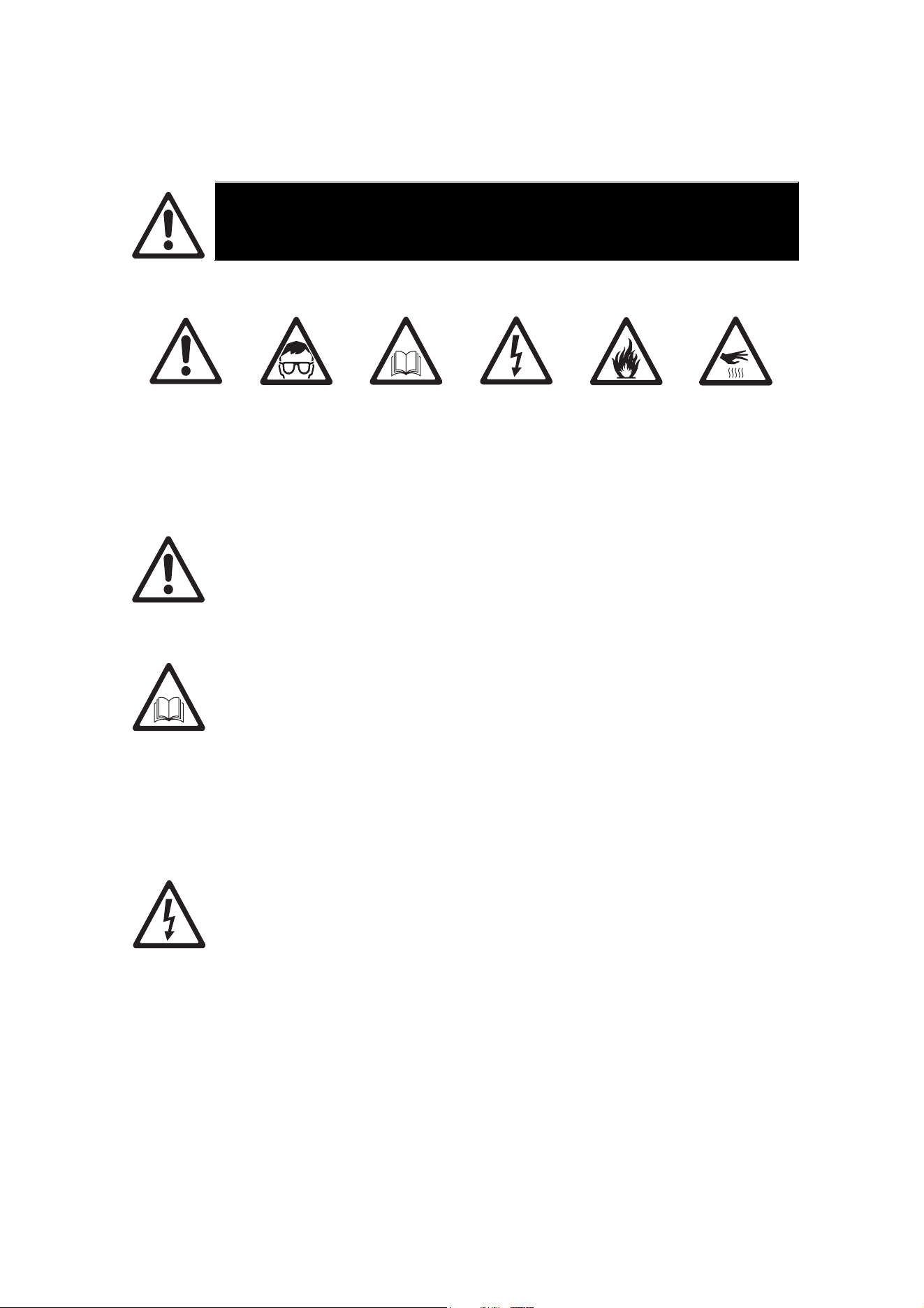
Safety information
WARNING!
Read the safety precautions in this manual before installing, operating or servicing
this product.
The following symbols are used to identify important safety information on the product and in this manual:
Warning!
Safety hazard.
Risk of severe
injury or
death.
Warning!
Powerful light
emission. Risk
of eye injury.
Warning!
See user
manual for
important
safety
information.
Warning!
Hazardous
voltage. Risk
of lethal or
severe electric
shock.
Warning!
Fire hazard.
Warning!
Hot surfaces.
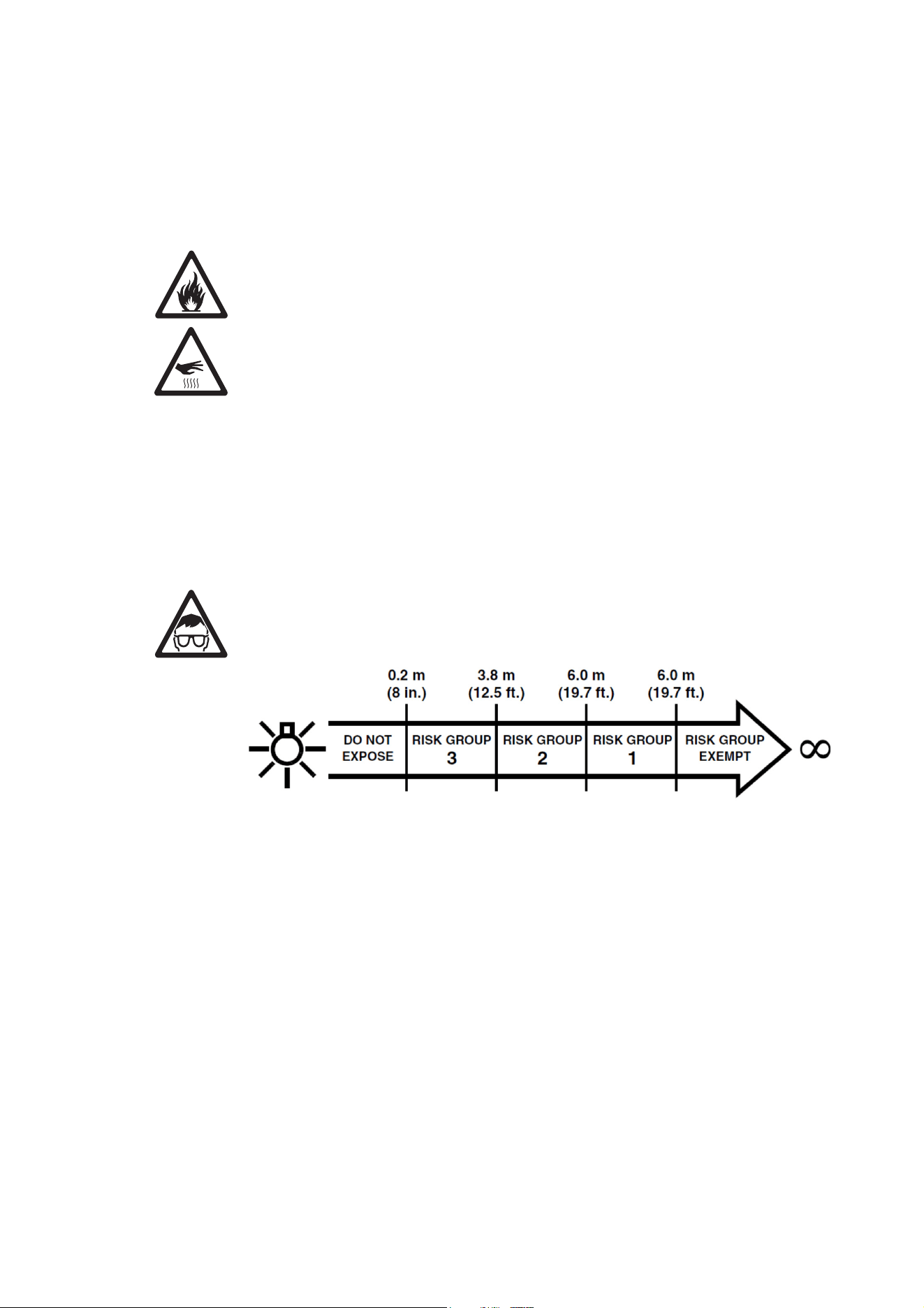
Warning! Risk Group 3 product according to EN 62471. Do not stare directly into the beam. Do
not view the light output with optical instruments or any device that may concentrate the beam.
This lighting fixture is for professional use only and must be installed by a qualified technician.
It is not for household use. It presents risks of severe injury or death due to fire hazards,
electric shock and falls. It can create a fire hazard or a risk of eye injury if the safety
precautions below are not followed.
Install, operate and service Martin products only as directed in their user manuals, or you may
create a safety hazard or cause damage that is not covered by product warranties. Follow the
safety precautions listed below and observe all warnings in this manual and printed on the
product. Keep this user manual for future use.
For the latest user documentation and other information about this and all Martin products,
please visit the Martin website at http://www.martin.com
If you have any questions about how to install, operate or service the fixture safely, please
contact your Martin supplier or call the Martin 24-hour service hotline for your region (see
Support Service at www.martin,com).
Respect all locally applicable laws, codes and regulations when installing, operating or
servicing the fixture.
Protection from electric shock
Ensure that the fixture is electrically connected to ground (earth).
Disconnect the fixture from AC power when not in use.
Never connect or disconnect a live Power + Data Cable. Shut down power to the fixtures
before connecting or disconnecting cables.
Do not open the fixture or remove any cover. Refer any service operation not described in this
manual to an authorized Martin Service partner.
Shut down power to the entire installation at the main power distribution board and lock out
power before carrying out any installation or maintenance work.
Use only a source of AC power that complies with local building and electrical codes and has
both overload and ground-fault (earth-fault) protection.
Isolate the fixture from power immediately if any seal, cover, cable, or other component is
damaged, defective, deformed or showing signs of overheating. Do not reapply power until
repairs have been completed.
Exterior Linear Series User Manual 5
Before using the fixture, check that all power distribution equipment and cables are in perfect
condition, are rated for the current requirements of all connected devices, are protected to IP67
or higher and are of suitable type for the location (including water, pollution, temperature and
UV resistance).
Do not immerse the fixture in water or any other fluid, or install it in a location where flooding
may occur.
Protection from burns and fire
Do not operate the fixture if the ambient temperature (Ta) exceeds 45° C (113° F).
The surface of the fixture can reach up to 85° C (185° F) if the fixture is operated at the
maximum permitted ambient temperature. Ensure that accidental physical contact with the
fixture is impossible. Allow the fixture to cool for at least 5 minutes before handling.
Install the fixture on a non-combustible surface (brick, concrete, plaster etc.) only.
Do not aim the fixture towards combustible materials (fabric, wood, paper etc.) that are within
10 cm (4 in.) of the fixture.
Keep the fixture well away from flammable materials (volatile liquids etc.).
Ensure that there is free and unobstructed airflow around the fixture.
Allow at least 0.1 m (4 in.) free space around the fixture.
Do not attempt to bypass thermostatic switches or fuses.
Do not modify the fixture in any way not described in this manual or install other than genuine
Martin parts. Do not stick filters, masks or other materials onto any lens or other optical
component. Use only accessories approved by Martin to modify the light beam.
Protection from eye injury
Exterior Linear fixtures fall into the following risk groups according to EN 62471 at the
distances indicated:
At a distance of less than 3.8 m (12.5 ft.) from the fixture, the light output can potentially cause
eye or skin injury before an exposed person’s natural aversion responses (blink reflex and
reaction to skin discomfort) can protect them. At distances greater than 3.8 m (12.5 ft.),
potential eye and skin injury hazards from the light output are normally prevented by natural
aversion reflexes.
Position the fixture so that persons cannot be exposed to the fixture’s light output at less than
3.8 m (12.5 ft.) from the fixture and so that prolonged staring into the light output at less than 6
m (19.7 ft.) from the fixture is not expected.
Do not look at the light output with magnifiers, telescopes, binoculars or similar optical
instruments that may concentrate the light output.
The risk group distances given above apply to the light output from one fixture only. If fixtures
are operated in combination light intensity can increase, and you should consult a lighting
professional for safety recommendations.
Provide well-lit conditions to reduce the pupil diameter of anyone working on or near the fixture.
Wear protective glasses and other PPE (personal protective equipment) when working on or
near the fixture.
6 Exterior Linear Series User Manual
Protection from injury
Fasten the fixture securely to a fixed surface or structure when in use. The fixture is not
portable when installed.
Ensure that all supporting structures, surfaces, fasteners and lifting equipment can bear the
weight of all the devices they are intended to support plus an adequate safety margin, and that
they conform to local building and safety regulations.
Ensure that any accessory such as a glare shield is securely fastened.
Block access below the work area and work from a stable platform whenever installing, setting,
adjusting, or cleaning the fixture.
Do not operate the fixture with missing or damaged covers, shields or any optical component.
If an operating problem occurs, stop using the fixture immediately and disconnect it from
power. Do not attempt to use a fixture that is obviously damaged.

Exterior Linear Series User Manual 7
Introduction
The Exterior Linear Series from Martin® is a line of rugged LED-based outdoor lighting fixtures. Exterior
Linear fixtures are available in three different light engine configurations and available in 305 mm (1 ft.)
and 1219 mm (4 ft.) length.
Cove models are designed for a range of indirect lighting applications. Graze models are designed for
illumination of walls or other surfaces and are available in narrow, medium, wide and asymmetric beam-
angle variants.
Exterior Linear 300/1200 RGBW
Dynamic color mixing using discrete Red, Green, Blue and neutral White Cree XP-E2 LEDs. This version
offers the most narrow beam angle configuration and optimum brightness for large scale graze lighting
applications.
Exterior Linear 310/1210 QUAD
Dynamic color mixing using quad-color premixed Osram Ostar LED for superior color mixing directly at the
lenses and to avoid multi-colored shadows. This version offers improved aesthetics where the fixture itself
is directly visible. A louvre accessory is available from Martin for improved visual comfort.
Exterior Linear 320/1220 CTC
Dynamic Color Temperature Control (CTC) version featuring cold-neutral-warm white Cree XP-E2 LEDs.
This version provides dynamic color temperature control in the range from 2700 K to 6500 K.
Features
All Exterior Linear Series fixtures feature:
• Long-life, high output LEDs
• Addressed via RDM and controlled by DMX.
• Functional and discreet optional glare shield and louvre
• The 4 ft. versions can be operated as a single unit or in individual 1 ft. segments
• IP66 ingress protection rating (suitable for permanent outdoor use)
• Built-in 100-277 V, 50/60 Hz auto-ranging AC power supply
• Easy wiring with combined power and data cables
• Local diagnostics called up by swiping magnet over fixture
Each fixture is supplied with two hinged mounting brackets.
Before using the product for the first time
1. Read ‘Safety information’ on page 4 before installing, operating or servicing the fixture.
2. Unpack and ensure that there is no transportation damage before using the fixture. Do not attempt to
operate a damaged fixture.
3. Before operating, ensure that the voltage and frequency of the power supply match the power
requirements of the fixture.
4. If fixtures are exposed to a sudden temperature change, give them time to warm or cool to the
ambient temperature before applying power. This will help avoid damage due to condensation.
5. Check the support pages on the Martin Professional website at www.martin.com for the most recent
user documentation and technical information about the fixture. Martin user manual revisions are
identified by the revision letter at the bottom of the inside cover.
Quad fixtures LED upgrade from 2022
From the beginning of 2022 all Exterior Linear QUAD variants are supplied with an updated Osram
OSTAR LED for improved light output and efficacy. QUAD fixtures are changing from 15 W to 20 W LEDs.
Total light output is increased by 37%. Efficacy is increased by 37%, as the fixture still consumes 20 W/ft.
Upgraded fixtures are identified with the letters MAR in front of the part number.
The color bins of the new LEDs match the previous ones exactly but the lumen output of each color has
not been increased evenly. Therefore we do not recommend that you mix the previous generation of
8 Exterior Linear Series User Manual
QUAD fixtures with the new generation in the same installation. If you do mix fixtures you will need to
program DMX values carefully in order to match certain mixed colors. See ‘Matching color in older and
newer QUAD fixtures’ on page 23 for guidelines on DMX values and matching colors.
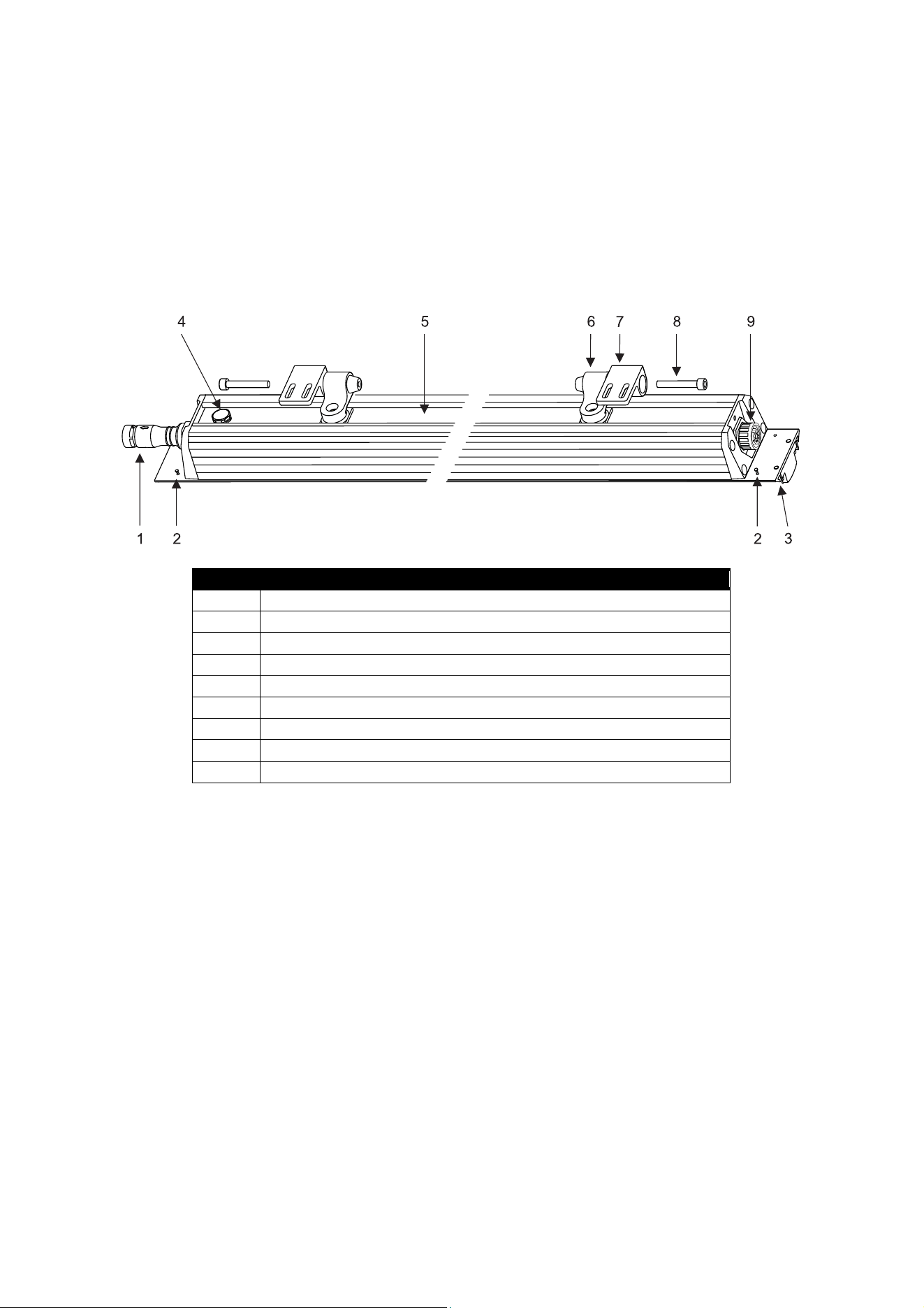
Fixture overview
Number Description
1 Power/data input
2 Accessory lock screw (4)
3 Accessory track (2)
4 Pressure relief valve
5 Mounting bracket track
6 Hinged mounting bracket (2)
7 Mounting flange (2)
8 Hinge bolt (2)
9 Power/data throughput
Exterior Linear Series Parts Identification
Exterior Linear Series User Manual 9
Physical installation
Warning! Read ‘Safety information’ on page 4 before installing the fixture.
Warning! The safety and suitability of lifting equipment, installation location, anchoring
method, mounting hardware and electrical installation are the responsibility of the installer.
All local safety regulations and legal requirements must be observed when installing and
connecting the Exterior Linear Series. Installation must be carried out by qualified
professionals only.
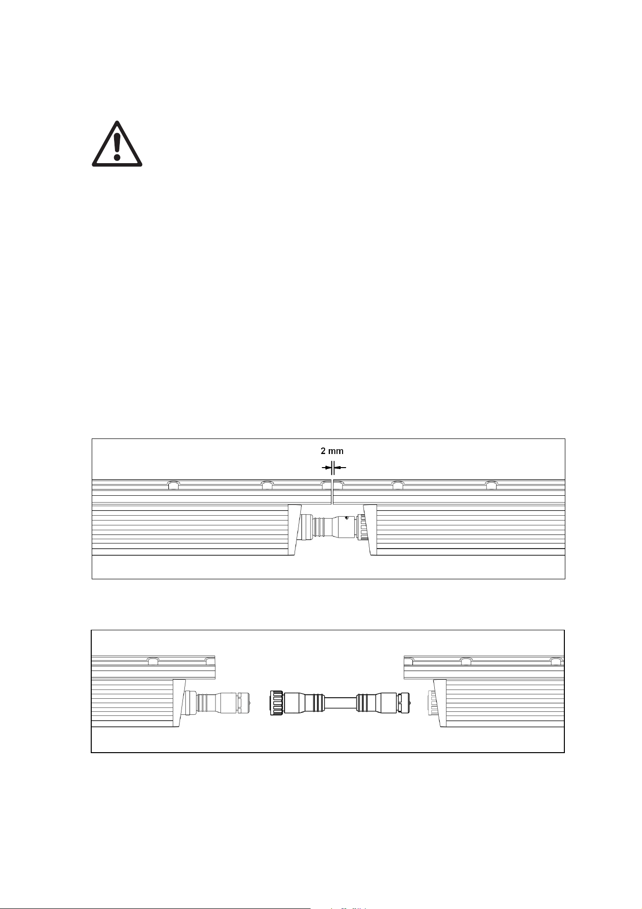
Important! Allow for thermal expansion by leaving free space at the ends of fixtures:
• Leave a 2 mm (0.08 in.) gap between the ends of fixtures when you install them in a
line.
• Leave a 2 mm (0.08 in.) gap between the ends of fixtures and fixed objects or surfaces.
Contact your Martin supplier for assistance if you have any questions about how to install this product
safely.
Fixture location
Exterior Linear Series fixtures are intended for outdoor use. With an IP rating of 66, they are dust-resistant
and able to withstand powerful water jets, but they are not submersible. Fixtures require free and
unobstructed airflow around them to ensure adequate cooling.
Observe the following limitations in selecting a location:
• Respect the limitations listed under Safety information’ on page 4.
• Do not allow water to collect on or near the pressure relief valve. Do not install the fixture in such a way
that water can form a pool covering the valve membrane.
• Ensure sufficient drainage to cope with the heaviest rainfall. Make sure that water can drain away from
the installation area at least as fast as it can enter it.
• Do not bury or locate the fixture in an unventilated space.
• If the fixture is operated at the maximum permitted ambient temperature, the housing can reach a
temperature of up to 85° C (185° F). Restrict public access or locate the fixture so that it cannot
accidentally be touched.
Mounting the fixture
Warning! All fasteners used to mount Exterior Linear Series fixtures
must be corrosion-resistant and strong enough to mount the fixture
safely. Install a washer directly under the head of each fastener when
anchoring the mounting bracket to the installation surface.
The fixture and mounting bracket are manufactured in corrosion-resistant anodized aluminum. Avoid direct
contact with other types of metal, as this can cause galvanic corrosion. When fastening a mounting
bracket or fixture to a metal surface that is not anodized aluminum:
• Use an electrically insulating material (such as rubber or plastic) or coating between the mounting
bracket and the other metal.
• Use a non-conductive coating such as Delta
Seal on fasteners (screws, bolts, washers, etc.)
where they come into contact with the
mounting bracket.
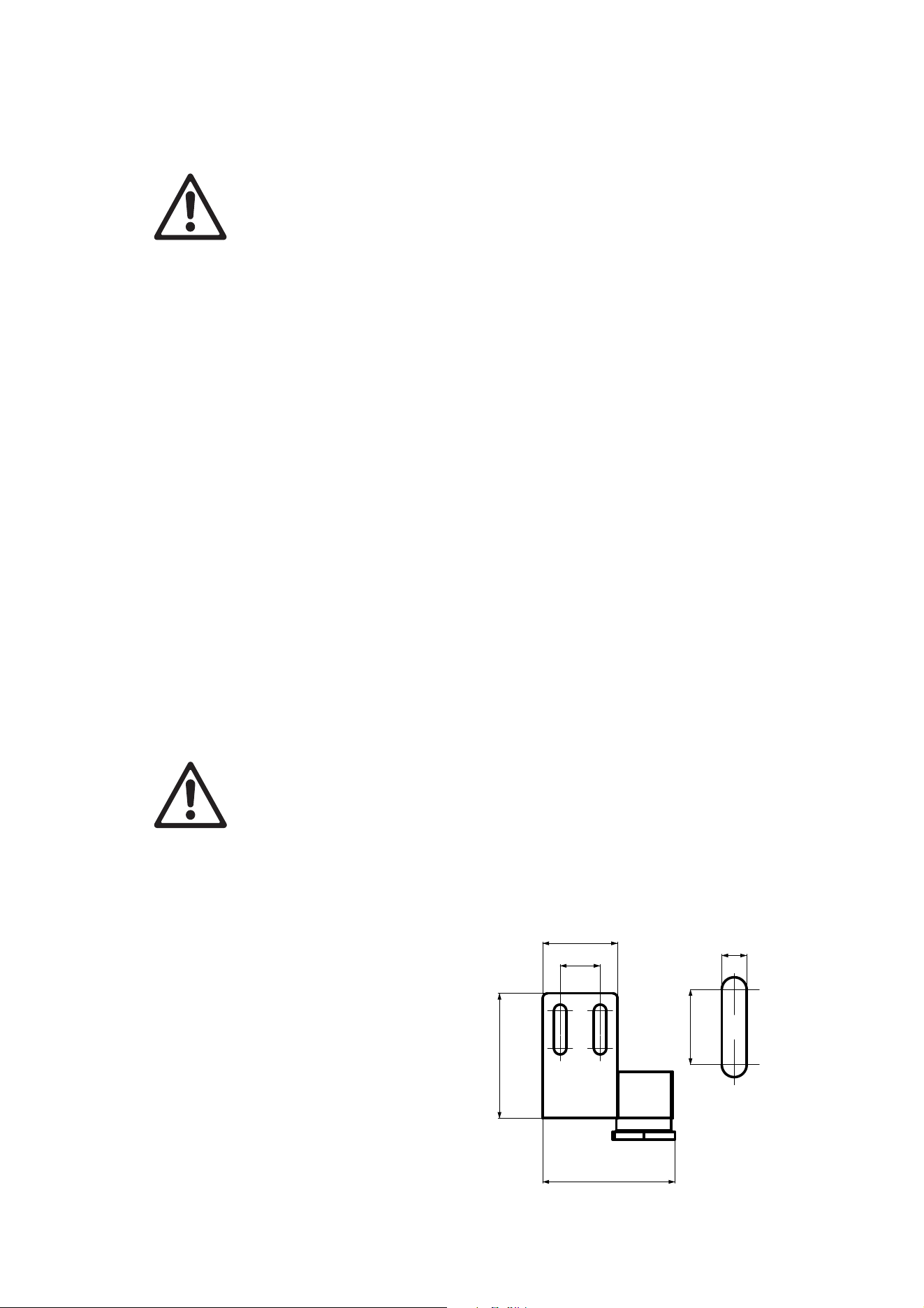
Mounting brackets
The fixture’s mounting brackets must be securely
anchored to a suitable support. The mounting
surface must be hard, fixed and flat. For bracket
dimensions see illustration on right.
The fixture can be mounted in any orientation.
The mounting brackets allow the fixture to be
manually tilted 105° for beam aiming adjustment.
B
DETAIL B
16
30
50
53
15
5
10 Exterior Linear Series User Manual
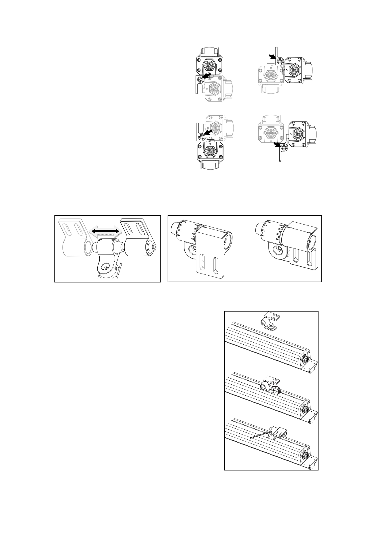
Mounting brackets can be fastened to fixtures in
various orientations. With the help of the illustration
on right, decide on the position that gives easiest
access to the Allen (hex) head bracket hinge bolt C
(so that you can adjust tilt) and to the elongated
holes in the mounting plate (so that you can tighten
fasteners to mount the fixture on the mounting
surface).
See illustrations below. The mounting plate A with two elongated holes that you fasten to the mounting
surface can be installed on either side of the hinge B in the bracket. This means that you can move the
mounting plate to whichever side of the hinge gives easiest access to the hinge bolt C for tilt adjustment.
You can also install the mounting plate facing towards or away from the fixture to give easiest access
when fastening the plate to the mounting surface.
To move the mounting plate A to the other side of the hinge B, unscrew and remove the Allen (hex) head
hinge bolt C, move the mounting plate with its rubber O-ring to the cone on the opposite side of the hinge,
turn the mounting plate so that it faces towards or away from the fixture as shown at D, then refasten the
hinge bolt C.
Installing mounting brackets
To install mounting brackets on a fixture:
1. Prepare two mounting brackets as described above and
loosen their hinge bolts C slightly.
2. See illustration on right. Align the long axis of the first
mounting bracket foot with the track in the back of the
fixture. Insert the foot in the track and rotate the bracket
through 90° so that the foot is captured in the track.
Tighten the Allen bolt in the bracket to lock the foot in the
track. Repeat for the second mounting bracket. Check that
both brackets are fastened securely to the fixture.
3. If necessary, adjust the position of the mounting plate as
described in the previous section to give easiest access to
the hinge bolt and fasteners.
A B
C
D
C
C
C
C
Exterior Linear Series User Manual 11
Fastening to the mounting surface
The fixture must be fastened to a stable surface with suitable mechanical fasteners. Do not stand it on a
surface or leave it where it can be moved or fall over. Ensure that the surface and all fasteners used can
support at least 10 times the weight of all the items that they will support.
1. See illustration above. Fasten the mounting plates A loosely to the mounting surface using two
suitable fasteners, one passed through each slot in the plate, with a washer between the head of
each fastener and the plate. Fasteners must be high-strength corrosion-resistant (recommended
minimum properties: stainless steel A4-70 grade according to ISO 3506 or steel grade 8.8 according
to ISO 898-1). All nuts used must be self-locking.
2. Refer to ‘Connecting power and data’ on page 15 and connect the fixture power + data input to the
output of the previous fixture.
3. Leave 2 mm (0.08 in.) free space at the end of each fixture to allow for thermal expansion. Adjust the
position of the mounting brackets as necessary, then fasten the fixture into position by tightening the
fasteners in the mounting plates A to fix the brackets to the mounting surface.
4. Pivot the fixture to the desired tilt angle, then tighten the hinge bolt C on each mounting bracket.
5. Check that the fixture is held securely and will not fall.
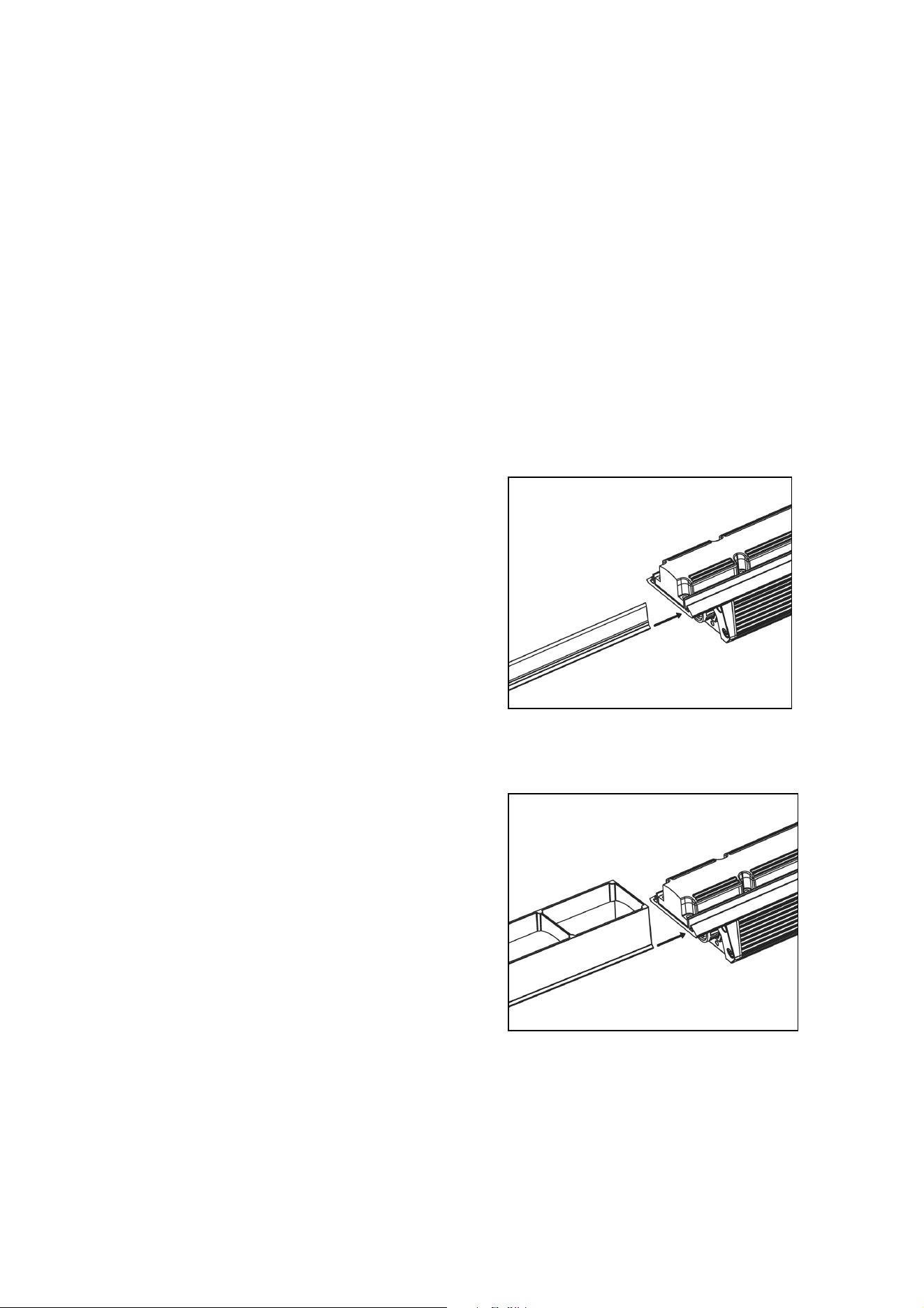
Installing a Glare Shield
Accessory Glare Shields designed to limit light spill are
available in 1 ft. (300 mm) and 4 ft. (1200 mm) lengths.
See ‘Accessories’ on page 26. Glare Shields are 25
mm (1 in.) high and slide into an accessory mounting
channel in the fixture profile.
To install a Glare Shield:
1. See illustration on right. Align the Glare Shield
with the mounting channel.
2. Slide the shield fully into the channel.
3. Secure the shield by fastening locking screws into
the holes provided at both ends of the fixture. If
you are installing a fixture at an angle that is not
horizontal, apply a thread locking compound such
as Loctite to the two screws before tightening
them.
Installing a Louvre (QUAD models)
Accessory Louvres designed to limit glare are
available in 1 ft. (300 mm) lengths for the Exterior
Linear QUAD Graze 310/1210. See ‘Accessories’ on
page 26.
Louvres are 40 mm (1.6 in.) high and slide into
accessory mounting channels in the fixture profile.
To install a Louvre:
1. See illustration on right. Align the Louvre with the
mounting channel.
2. Slide the louvre fully into the channel.
3. Secure the louvre by fastening locking screws into
the holes provided at both ends of the fixture. If
you are installing a fixture at an angle that is not
horizontal, apply a thread locking compound such
as Loctite to the two screws before tightening them.
12 Exterior Linear Series User Manual
AC power and data connection
Warning! Read ‘Safety information’ on page 4 before installing the fixture.
Never connect or disconnect a live power and data cable. Shut down power to the
installation before connecting or disconnecting cables.
Make sure that cables from fixtures open into dry areas (e.g. junction boxes in dry
locations). If there is a break or cut at any point in a cable (for example at a connection
point), and if this is exposed to water, moisture can be drawn up the inside of the cable due
to the vacuum effect of temperature fluctuations during operation. Ensure that the fixture is
protected from the entry of water via the power cable by using IP66-rated connectors or
junction boxes, or by protecting connectors with weatherproof housings.
Exterior Linear Series fixtures accept AC power at 100 - 277 V nominal, 50 or 60 Hz. Do
not connect to power at any other voltage or frequency.
There is no power on/off switch. Power is applied to the fixtures as soon as they are
connected to power. Provide a means to disconnect or shut down power to fixtures that is
easily accessible and is located close to the fixtures.
Do not use an external dimming system to supply power to the fixture, as this may cause
damage to the fixture that is not covered by the product warranty.
Power requirements
Exterior Linear Series fixtures must be supplied with AC mains power at 100 - 277 V nominal, 50/60 Hz
using either a grounded single-phase (live, neutral, ground/earth) distribution system or one phase of a
grounded three-phase (3 live phases, neutral, ground/earth) distribution system.
Fixtures are designed to be connected directly to each other: power/data output to power/data input as
shown below (leaving a 2 mm / 0.08 in. thermal expansion gap between fixtures).
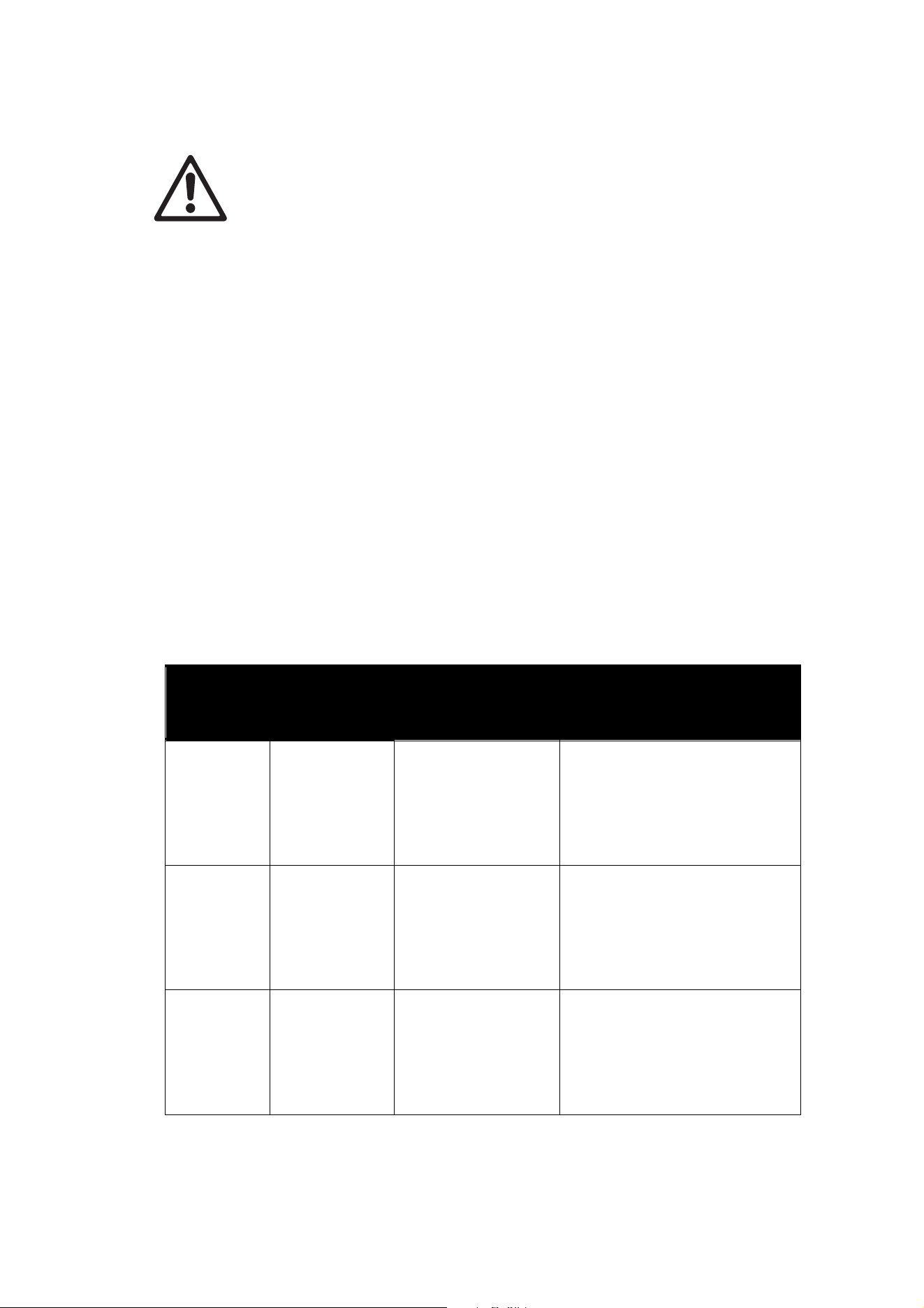
They can also be connected using the 0.2 m (7.8 inch), 1. 5 m (4.9 ft.) or 10 m (32 ft.) extension cables
listed under ‘Accessories’ on page 26.
Exterior Linear Series User Manual 13
Safety limits for chains of fixtures
Warning! Read this section carefully and respect the safety limits given, or you may create
a risk of fire or electric shock. Consult your Martin supplier if you have any questions about
installation safety.
Maximum total length of fixtures
The maximum permitted total length of fixtures, excluding cable, that you can connect in one chain is:
• 50 ft. (15.2 m) of fixtures at 120 V mains power
• 100 ft. (30.5 m) of fixtures at 240 V mains power
• 120 ft. (36.5 m) of fixtures at 277 V mains power
Maximum total length of cable
If a chain contains the permitted maximum total length of fixtures, the maximum total length of cable that
you can add to add to the chain (as a lead-in before the first fixture and between fixtures) is:
• 230 ft. (70 m) of cable at 120 V mains power if the chain contains the permitted maximum of 50 ft.
(15.2 m) of fixtures
• 328 ft. (100 m) of cable at 240 V mains power if the chain contains the permitted maximum of 100 ft.
(30.5 m) of fixtures
• 328 ft. (100 m) of cable at 277 V mains power if the chain contains the permitted maximum of 120 ft.
(36.5 m) of fixtures
Maximum total length of cable if total length of fixtures is less than the maximum
If the chain contains less than the permitted maximum length of fixtures, the maximum permitted length of
cable that you can add to the chain increases. See the table below for details.
Maximum lengths of fixtures and cable in chains of Exterior Linear fixtures
Voltage Maximum
permitted total
length of fixtures
in chain
Maximum permitted
total length of cable in
chain
Increase in maximum permitted
total length of cable if total length of
fixtures is reduced
110 – 120 V 50 ft. (15.2 m) 230 ft. (70 m)
For every 5 ft. (1.5 m) of fixtures
that you remove from the 50 ft.
(15.2 m) maximum total length of
fixtures in the chain, you can add
32 ft. (10 m) of cable to the 230 ft.
(70 m) maximum permitted total
length of cable in the chain.
220 – 240 V 100 ft. (30.5 m) 328 ft. (100 m)
For every 10 ft. (3 m) of fixtures that
you remove from the 100 ft.
(30.5 m) maximum total length of
fixtures in the chain, you can add
32 ft. (10 m) of cable to the 328 ft.
(100 m) maximum permitted total
length of cable in the chain.
277 V 120 ft. (36.5 m) 328 ft. (100 m)
For every 10 ft. (3 m) of fixtures that
you remove from the 120 ft.
(36.5 m) maximum total length of
fixtures in the chain, you can add
32 ft. (10 m) of cable to the 328 ft.
(100 m) maximum permitted total
length of cable in the chain.
In configurations where additional cable is mainly inserted
towards the end
of the chain, it may be possible
to exceed slightly the maximum permitted total cable lengths given above. However, you may only exceed
these maximum lengths in consultation with authorized Martin personnel or agents. Exceeding the

14 Exterior Linear Series User Manual
maximum permitted total number of fixtures or maximum permitted total length of cable in a chain may
create a risk of fire or electric shock if the total current draw in the chain is not carefully calculated.
Cable types
The first fixture in the chain is intended to be wired directly to a building’s AC mains power supply and to
the control data link inside a suitable weatherproof junction box. Cables for this purpose are available for
compliance with US and EU electrical codes.
North American
type (PVC cable)
EU type
(rubber cable)
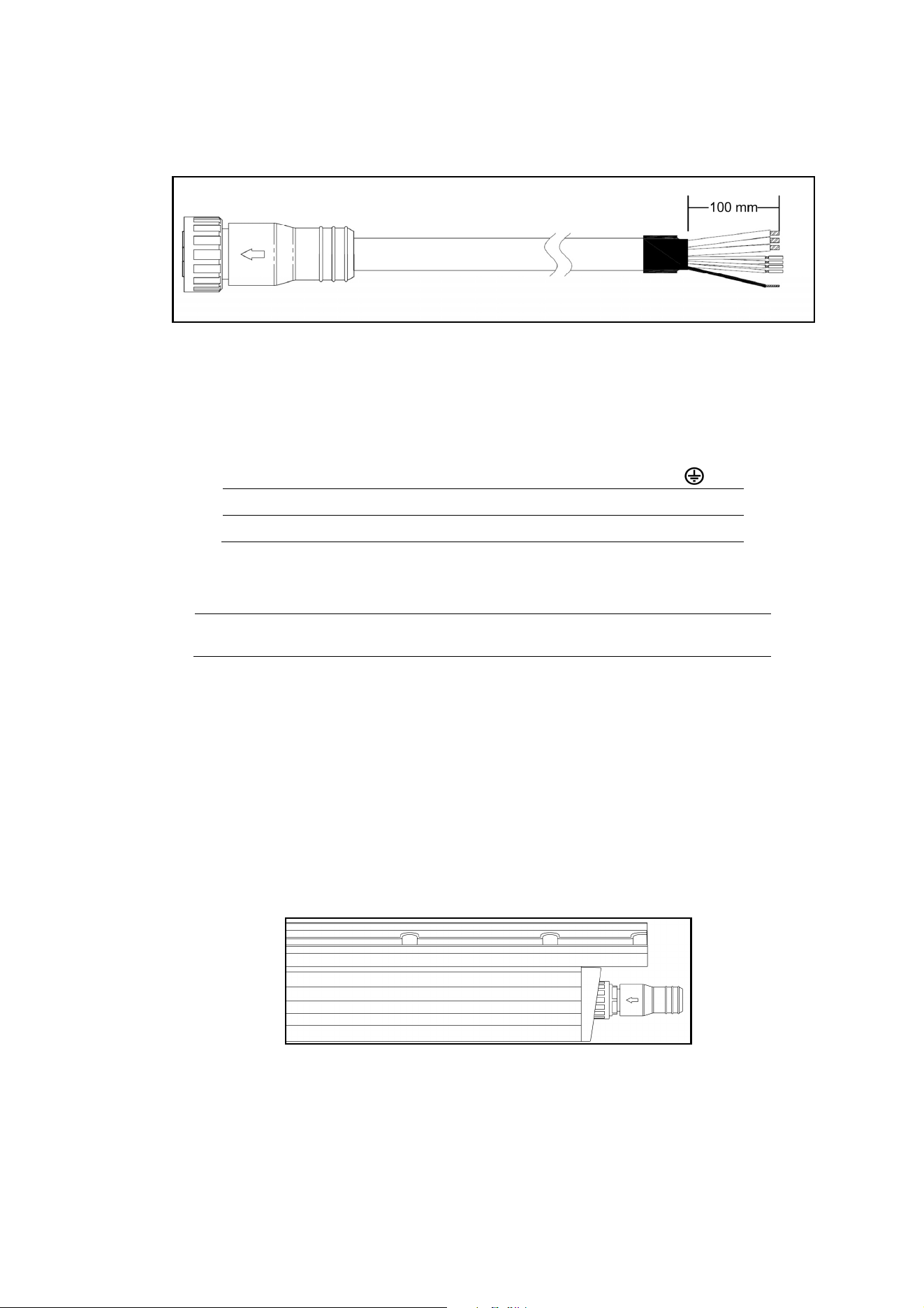
Power + Data Input Cable with 8-pin custom connector,
2 m (6.6 ft.)
P/N 91611755 P/N 91611754
Power + Data Input Cable with 8-pin custom connector,
10 m (32.8 ft.)
P/N 91611157 P/N 91611156
In other locations, consult with your Martin distributor to determine the appropriate cable type.
Extension cables for relaying power and data between fixtures are also available in various lengths and
types (see Accessories on page 26).
Data network requirements
The lighting controller connects to Exterior Linear Series fixtures through the combined power and data
cables. As with power, the first fixture in the chain is intended to be wired directly to the DMX data network
inside a suitable weatherproof junction box.
Though other configurations are possible, the recommended configuration for the data network is to use
one DMX universe for each chain of Exterior Linear Series fixtures. The following considerations must be
taken into account when laying out the data network:
• 512 DMX channels are available in a single DMX universe. Each time the combined channel
requirements of a group of connected fixtures exceeds 512, an additional DMX universe will be
required.
• You can reliably connect up to 32 fixtures in a single daisy chain.
• Use RS-485 data cable designed for exterior use. RS-485 cable has low capacitance and a
characteristic impedance of 85 to 150 Ohms. It is electrically shielded and has at least 1 twisted pair of
conductors. The minimum recommended wire size is 0.25 mm2 (24 AWG) for runs up to 200 meters
(1000 ft.) and 0.32 mm2 (22 AWG) for runs up 500 meters (1640 ft).
• Branches may be added to the link using an opto-isolated splitter. Be sure to use an RDM compatible
amplifier-splitter such as the Martin 5.5 Splitter. Each branch may itself connect up to 32 fixtures.
• An RDM amplifier may also be used to extend a network beyond 500 meters (1640 ft.) or to connect up
to 32 additional fixtures to the daisy chain.
• The data link and each connected branch must be terminated at the end by installing an End
Termination Cap for power + data link, P/N 91611766, on the output of the last fixture on the chain.
• Long parallel runs of AC power and control data cables may cause interference on the data link and
must be avoided. Even if not required by law, use separate conduits for power and data cables.
• Make sure that data connections are totally protected from water, or the suction created by normal
heating and cooling may suck moisture up the inside of the cable and into fixtures.
• Exterior Linear Series fixtures and cables support but do not use the second DMX data pair. The data
network therefore can, but need not include the second data pair.
Exterior Linear Series User Manual 15
Connecting power and data
Power + Data Input Cable
To connect a single fixture or the first fixture in a fixture chain to power and data:
1. Lock out power to the installation.
2. Connect the conductors in the Power and Data Input Cable to the power distribution circuit and DMX
data link as follows:
Power conductors
Live or L Neutral or N
Earth, Ground or
US system
Black White Green
EU system
Brown Blue Yellow/green
Data conductors
Shield /
common
Data 1
cold (-ve)
Data 1
hot, (+ve)
Data 2
cold (-ve)*
Data 2
hot, (+ve)*
All systems
Copper braid
(pin 1)
Red
(pin 2)
Grey
(pin 3)
Green
(pin 4)
White
(pin 5)
*Both DMX and RDM signals are carried on Data 1 conductors. Data 2 connections are optional.
3. Plug the connector on the Power + Data Input Cable into the input socket on the fixture and screw
tight by hand. Do not use tools to tighten input connectors.
4. Check that all installation work is completed and carry out appropriate tests and safety checks before
applying power.
To connect power and data to additional fixtures:
1. Lock out power to the installation. Never connect or disconnect a live Power + Data Cable!
2. Connect one fixture’s power/data throughput connector to the next fixtures power/data input
connector, either directly or with extension cables.
3. Install a termination cap in the throughput connector of the last fixture in the chain as shown below.
Exterior Linear Termination Cap
4. Ensure that all connections are tight and secure.
5. Check that all installation work is completed and carry out appropriate tests and safety checks before
applying power.

16 Exterior Linear Series User Manual
Setup
RDM
Exterior Linear Series fixtures require an RDM-compatible controller that is connected to the installation
via a DMX data link to check and alter fixture settings, send control commands and retrieve fixture data.
A full list of the RDM functions that Exterior Linear fixtures support is given at the end of this chapter.
These functions are generally referred to using the more specific term ‘PIDs’ or ‘Parameter IDs’.
The exact procedures and command names used in different RDM controllers vary. This section gives
examples of typical procedures only – your RDM controller may handle procedures differently.
Step one: scanning for devices on the data link
Before you can communicate with fixtures using RDM, you must send a scan command (also called a
device discovery command) to all the devices on the data link so that the RDM controller can identify
them. It does this by retrieving each device’s factory-set unique identifier (UID). This process can take
some time depending on the number of devices on the link.
To identify the fixtures on the link:
1. Check that the fixtures are correctly connected to the RDM controller on the data link and that power
is applied to all fixtures.
2. Send a discovery command via RDM. This command will be labeled SCAN, DISCOVER DEVICES or
something similar, depending on the RDM controller you use.
3. Give the controller time to identify the devices on the link and prepare for communication with the
devices.
Setting up DMX behavior
Setting DMX mode
This command lets you set the DMX mode of fixtures on the data link. Because DMX mode affects the
number of DMX channels a fixture uses, it will affect the assignment of DMX addresses to fixtures. You
should therefore set fixtures’ DMX mode before you set their DMX addresses.
Exterior Linear fixtures can be set to either Standard DMX mode – STD MODE or Extended DMX mode –
EXD MODE. Extended mode offers additional control functions but uses more DMX channels. See the
'DMX protocol section at the end of this manual for an overview of the functions available and number of
DMX channels used.
You can set the DMX mode of one fixture by sending a unicast RDM command to that one fixture only, or
you can set the DMX mode of all the fixtures on the data link by sending a broadcast RDM command to all
the devices on the link.
An example procedure might look like this, depending on which RDM controller you use:
1. Go to Scan Properties Device Info Change personality.
2. Select EXD MODE or STD MODE.
3. Press ENTER to confirm your selection.
Setting DMX addresses
This command lets you set the DMX addresses of fixtures on the data link.
A fixture’s DMX address is the first DMX channel it uses to receive data communication. It uses this
channel and the channels immediately above it. If a fixture has DMX address 001 and the fixture uses four
DMX channels, it will use channels 001, 002, 003 and 004. DMX address 005 will be available as a DMX
address for the next fixture on the data link. If this fixture also uses four DMX channels, the next available
DMX address will be 009, and so on.
You can set the DMX address of one fixture by sending a unicast RDM command to that one fixture only,
or you can set all the fixtures on the data link to the same DMX address by sending a broadcast RDM
command to all the devices on the link. If all the fixtures have the same DMX address, they will behave
identically and you will not be able to control any single fixture independently.
An example procedure might look like this, depending on which RDM controller you use:
1. Go to Scan Properties Advanced Choose PID SET DMX START ADDRESS.
Exterior Linear Series User Manual 17
2. Enter the DMX address that you want to give to the fixture (or give to all the fixtures if you are sending
a broadcast command).
3. Confirm your selection.
Setting behavior when no DMX signal is present
This command lets you set the behavior of fixtures on the data link when the fixtures are not receiving
DMX.
You can set behavior in one fixture by sending a unicast RDM command to that one fixture only, or you
can set behavior in all the fixtures on the data link by sending a broadcast RDM command to all the
devices.
Three options are available: Explanation:
Blackout Fixture intensity set to zero light output when no DMX signal is
received.
Dft slted val. (Default selected DMX
value)
All LEDs go to 100% intensity when no DMX signal is received.
Last rcved val (Last received DMX
value)
Fixtures store the last DMX values they received in memory and
use those values when no DMX signal is being received. This lets
you set up how fixtures will appear each time they are powered
on. If you create a scene by sending DMX values to the fixtures
and then power the fixtures off, the fixtures will display that scene
again each time you power them on, even if no DMX signal is
present
An example procedure might look like this, depending on which RDM controller you use:
1. Go to Scan Properties Device Info Change personality.
2. The currently selected behavior is displayed.
3. Select Blackout, Dft slted val. or Last rcved val.
4. Confirm your selection.
Temperature, current draw and refresh rate status
You can display the following status information from the fixture:
• Temp – Fixture temperature.
• Amp – Fixture’s current draw in amps
• Refresh rate – Fixture’s LED refresh rate
An example procedure might look like this, depending on which RDM controller you use:
1. Go to DISCOVER DEVICES Get Sensor value.
2. Scroll and display temperature, current draw in amps and LED refresh rate for all fixtures.
Overall fixture status
You can display general status information for a fixture.
An example procedure might look like this, depending on which RDM controller you use:
1. Go to DISCOVER DEVICES Status check.
2. Overall fixture status is displayed.
18 Exterior Linear Series User Manual
RDM
As a minimum, Exterior Linear fixtures support the following RDM functions:
Device discovery
DISC_UNIQUE_BRANCH
DISC_MUTE
DISC_UN_MUTE
Device management
GET SET
SUPPORTED_PARAMETERS
DEVICE_INFO
DEVICE_MODEL_DESCRIPTION
MANUFACTURER_LABEL
DEVICE_LABEL
FACTORY_DEFAULTS
SOFTWARE_VERSION_LABEL
DMX_PERSONALITY
DMX_PERSONALITY_DESCRIPTION
DMX_START_ADDRESS
SLOT_DESCRIPTION
SENSOR_DEFINITION
SENSOR_VALUE
DEVICE_HOURS
LAMP_HOURS
LAMP_STATE (ON/OFF)
DEVICE_POWER_CYCLES
DISPLAY_LEVEL
IDENTIFY_DEVICE
RESET_DEVICE
Exterior Linear Series User Manual 19
Maintenance
Warning! There are no user-serviceable parts inside. Do not open the housing. Refer any
service operation not described in this manual to Martin Professional™ or its authorized
service agents.
The only service operation the user can carry out on Exterior Linear Series fixtures is
occasional cleaning.
Be aware that the output of LEDs, like all light sources, changes gradually over many thousands of hours
of use. If you require products to perform to very precise color specifications, you may eventually need to
make small readjustments at the lighting controller.
The light source in this product is not user-replaceable. When the light source LEDs reach the end of their
service life, they may be replaced only by Martin Service, an authorized Martin Service agent or a similarly
qualified person.
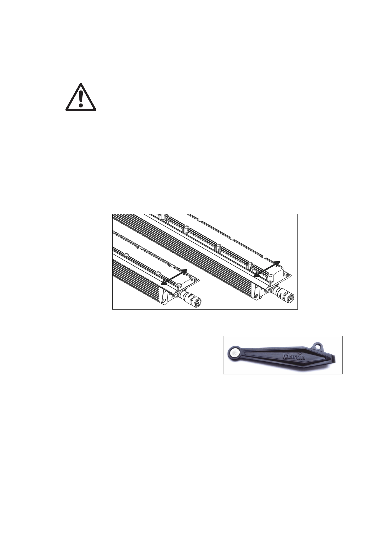
Running test sequences
Exterior Linear Series fixtures are programmed with a test sequence that is activated by ‘swiping’ (moving)
a magnet past a magnetic switch inside the fixture. The magnetic switch is located between the last two
LEDs at the end of the fixture with the power + data input connection as shown below.
Swipe magnet across Exterior Linear Cove (left) or Graze (right)
We recommend that you use the Martin Service Tool
shown to right, which contains a suitable magnet. See
‘Related Items’ on page 27.
Activating the magnetic switch lets you display the
product’s status and test the LEDs.
Exterior Linear RGBW/QUAD models (300/310/1200/1210 Cove, 300/310/1200/1210 Graze)
Swiping a magnet past the magnetic switch causes the fixture to step through the following sequence:
1. Display status code (see table below for meaning).
2. All LEDs at full intensity.
3. All red LEDs at full intensity.
4. All green LEDs at full intensity.
5. All blue LEDs at full intensity.
6. All white LEDs at full intensity.
7. All LEDs at 20% intensity.
8. Exit sequence and resume normal operation.
You can also resume normal operation by cycling power off and on. If you are sending a DMX signal to the
fixture, it will exit the sequence and enter normal DMX operation again after a short period.
20 Exterior Linear Series User Manual
Fixture status is indicated as follows:
LED color Signal Status
Blue Fast flash Busy (booting or uploading SW)
Blue Slow flash No DMX detected
Green/blue Alternating Running normally in DMX mode
Exterior Linear color temperature control (CTC) models (320/1220 Cove, 320/1220 Graze)
Swiping a magnet past the magnetic switch causes the fixture to step through the following sequence:
1. Display status code (see table below for meaning).
2. All LEDs at full intensity.
3. All cold white LEDs at full intensity.
4. All neutral white LEDs at full intensity.
5. All warm white LEDs at full intensity.
6. All LEDs at 20% intensity.
7. Exit sequence and resume normal operation.
You can also resume normal operation by cycling power off and on. If you are sending a DMX signal to the
fixture, it will exit the sequence and enter normal DMX operation again after a short period.
Fixture status is indicated as follows.
LED color Signal Status
Cold Fast flash Busy (booting or uploading SW)
Cold Slow flash No DMX detected
Cold/warm Alternating Running normally in DMX mode
Managing humidity
Exterior Linear Series fixtures are IP66-rated and are designed to resist water and moisture in
environments with widely varying climate, temperature and humidity conditions. But if fixtures are not
managed correctly during installation and service, water and moisture can enter, leading to humidity and
condensation inside the fixtures. Follow the precautions in this chapter to avoid this problem.
General
• Air, and even water, can be sucked along cables and into fixtures. A cracked or porous cable jacket
can allow water into the cable. Replace any cable that is not in perfect condition. Make sure that cables
from fixtures open into dry areas (e.g. junction boxes in dry locations).
• Do not clean fixtures with high-pressure water jets or immerse them.
Pressure relief valve
A valve with a Gore-Tex membrane on the back of the fixture equalizes pressure by allowing air to pass
through it when the fixture heats up and cools down, but at the same time it acts as a barrier to water in
liquid form. The expulsion of warm air (with a slightly higher water vapor content) and intake of cool air
(with a slightly lower water vapor content) prevents humidity buildup over time, provided that the valve
works correctly and the fixture is correctly sealed.
Pressure relief valves have a limited service life. They become blocked over time as the micropores in the
membrane fill with particles. When a valve becomes blocked, excess pressure can damage seals or cause
air and even water to be sucked into the fixture along cables. A blocked valve cannot be cleaned and must
be replaced if it shows any signs of contamination or is not in perfect condition.
For maximum fixture service life, have the pressure relief valve replaced after an extended period of use.
Intervals for valve replacement depend on the installation environment. Please consult your Martin dealer
about a suitable replacement schedule. To ensure optimum humidity control, valve replacement must be
carried out by Martin Service.

Exterior Linear Series User Manual 21
Cleaning
Regular cleaning is essential for fixture life and performance. Buildup of dust and dirt degrades the
fixture’s light output and cooling ability.
Cleaning schedules will vary greatly depending on the operating environment. It is therefore impossible to
specify precise cleaning intervals for the Exterior Linear Series. Inspect fixtures within their first few weeks
of operation to see whether cleaning is necessary. Check again at frequent intervals. This procedure will
allow you to assess cleaning requirements in your particular situation. If in doubt, consult your Martin
dealer about a suitable maintenance schedule.
Do not use products that contain solvents, abrasives or caustic agents for cleaning, as they can cause
surface damage to the fixture. The aluminum housing and front glass can be cleaned with mild detergents
such as those for washing cars.
To clean the housing and front glass:
1. Visually check that the silicone seals and the power and data cables are in good condition. If any seal
or cable shows signs of damage, cracking or loss of water resistance, stop cleaning the fixture and
contact a Martin authorized service technician for replacement.
2. If seals are in good condition, rinse off loose dirt with a hose or low-pressure water spray.
3. Wash the aluminum housing and front glass using warm water with a little mild detergent and a soft
brush or sponge. Do not use abrasive cleaners.
4. Rinse with clean water and wipe dry.
22 Exterior Linear Series User Manual
DMX protocol
Exterior Linear Series 300/310 & 1200/1210 RGBW/QUAD
models
RGBW color mixing models offer 0 to 100% intensity control of red, green, blue and white:
• Standard DMX mode gives RGBW control of the fixture using one channel per color. Fixtures in
standard mode therefore use four DMX channels.
• Extended DMX mode is available on 1200 models. Extended mode gives independent RGBW control
of four 300 mm segments. 1200 models in extended mode therefore use sixteen DMX channels.
Channel,
Standard
Mode
Channels,
Extended
Mode
Value Function
1 1, 5, 9, 13 0-255 Red: 0-100%
2 2, 6, 10, 14 0-255 Green: 0-100%
3 3, 7, 11, 15 0-255 Blue: 0-100%
4 4, 8, 12, 16 0-255 White: 0-100%
Exterior Linear Series 320 & 1220 color temperature control
(CTC) models
Variable white models offer 0 to 100% dimming control and color temperature control from 2700 K to
6500 K:
• Standard DMX mode uses one channel to control intensity and one channel to control color
temperature. Fixtures in standard mode therefore use two DMX channels.
• Extended DMX mode is available on 1220 models. Extended mode gives independent color
temperature control of four 300 mm segments. 1220 models in extended mode therefore use eight
DMX channels.
• Standard three-channel DMX mode uses one channel to control 2700 K intensity, one to control
4000 K intensity and one to control 6500 K intensity.
• Extended three-channel DMX mode is also available on 1220 models. Extended three-channel mode
uses one channel to control 2700 K intensity, one to control 4000 K intensity and one to control 6500 K
intensity independently on four 300 mm segments. 1220 models in extended mode therefore use
twelve DMX channels.
Standard and Extended modes
Channel,
Standard
Mode
Channels,
Extended
Mode
Value Function
1 1, 3, 5, 7 0-255 Intensity 0-100%
2 2, 4, 6, 8
0
1-255
No function
Color temperature 2700-6500 K
Exterior Linear Series User Manual 23
Standard 3-channel and Extended 3-channel modes
Channel,
Standard
3-Channel
Mode
Channels,
Extended
3-Channel
Mode
Value Function
1 1, 4, 7, 10 0-255 2700 K intensity 0-100%
2 2, 5, 8, 11 0-255 4000 K intensity 0-100%
3 3, 6, 9, 12 0-255 6500 K intensity 0-100%
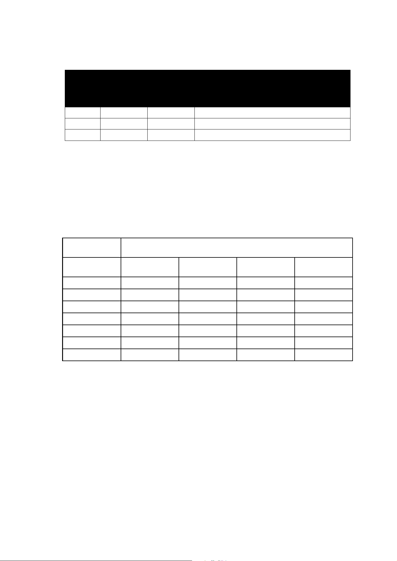
Matching color in older and newer QUAD fixtures
QUAD fixtures with part numbers starting MAR- are fitted with upgraded LEDs that provide improved light
output with the same overall power consumption for the fixture. If you mix the original QUAD fixtures with
newer MAR-xxxxxxxx QUAD fixtures in the same installation and if you want to match the color of the
original and newer fixtures, you will need to use different DMX values in the newer fixtures compared to
the original fixtures. The table below gives you an indication of the values that you can use as a starting
point, but note that further fine-tuning will probably be required.
Original QUAD
fixtures
Newer QUAD fixtures with upgraded LEDs
DMX value sent
to fixture
Red channel Green channel Blue channel White channel
100 100 100 x 0.85 = 85 100 x 0.80 = 80 100 x 0.90 = 90
75 75 75 x 0.85 = 64 75 x 0.80 = 60 75 x 0.90 = 68
50 50 50 x 0.85 = 43 50 x 0.80 = 40 50 x 0.90 = 45
25 25 25 x 0.85 = 21 25 x 0.80 = 20 25 x 0.90 = 23
10 10 10 x 0.85 = 9 10 x 0.80 = 8 10 x 0.90 = 9
5 5 5 x 0.85 = 4 5 x 0.80 = 4 5 x 0.90 = 5
0 0 0 x 0.85 = 0 0 x 0.80 = 0 0 x 0.90 = 0

24 Exterior Linear Series User Manual
Specifications
Physical
300/310/320 Cove
Length .............................................................................................................................. 305 mm (12.0 in.)
Width .................................................................................................................................... 72 mm (2.8 in.)
Height ....................................................................................................... 95 mm (3.8 in.) including bracket
Weight ................................................................................................................................. 1.6 kg (3.6 lbs.)
300/320 Graze
Length .............................................................................................................................. 305 mm (12.0 in.)
Width .................................................................................................................................... 72 mm (2.8 in.)
Height ....................................................................................................... 99 mm (3.9 in.) including bracket
Weight ................................................................................................................................. 1.5 kg (3.4 lbs.)
310 Graze
Length .............................................................................................................................. 305 mm (12.0 in.)
Width .................................................................................................................................... 72 mm (2.8 in.)
Height ..................................................................................................... 103 mm (4.1 in.) including bracket
Weight ................................................................................................................................. 1.5 kg (3.4 lbs.)
1200/1210/1220 Cove
Length ............................................................................................................................ 1219 mm (48.0 in.)
Width .................................................................................................................................... 72 mm (2.8 in.)
Height ....................................................................................................... 95 mm (3.8 in.) including bracket
Weight ............................................................................................................................... 6.4 kg (14.2 lbs.)
1200/1220 Graze
Length ............................................................................................................................ 1219 mm (48.0 in.)
Width .................................................................................................................................... 72 mm (2.8 in.)
Height ....................................................................................................... 99 mm (3.9 in.) including bracket
Weight ............................................................................................................................... 6.0 kg (13.3 lbs.)
1210 Graze
Length ............................................................................................................................ 1219 mm (48.0 in.)
Width .................................................................................................................................... 72 mm (2.8 in.)
Height ..................................................................................................... 103 mm (4.1 in.) including bracket
Weight ............................................................................................................................... 6.0 kg (13.3 lbs.)
Dynamic Effects
300/310/1200/1210 Cove, 300/310/1200/1210 Graze
Intensity ......................................................................................................................................... 0 - 100%
Color mixing ..................................................................................................................................... RGBW
320/1220 Cove, 320/1220 Graze
Intensity ......................................................................................................................................... 0 - 100%
Color temperature control ..................................................................................................... 2700 - 6500 K
Control and Programming
Control systems .........................................................................................................................DMX, RDM
DMX compliance ....................................................................................................... USITT DM
X512/1990
RDM compliance ............................................................................................................. ANSI/ESTA E1.20
User interface ........................................................ Magnetic switch to call up fixture status and test fixture
300/310/1200/1210 Cove, 300/310/1200/1210 Graze
DMX channels, standard / extended mode* .......................................................................................... 4/16
320/1220 Cove, 320/1220 Graze
DMX channels, standard / extended / 3-channel standard / 3-channel extended mode* ................ 2/8/3/12
*Extended modes are available on 1200, 1210 and 1220 models only

Exterior Linear Series User Manual 25
Optics
300/320/1200/1220 Cove
Light source .................................................................................................................. CREE XP-E2 LEDs
Minimum LED lifetime ................................................................. 50 000 hours (to >70% luminous output)*
Beam angle .......................................................................................................................................... 120°
310/1210 QUAD Cove
Light source ................................................................................................. OSRAM OSTAR S2WM LEDs
Minimum LED lifetime ................................................................. 50 000 hours (to >70% luminous output)*
Beam angle .......................................................................................................................................... 105°
300/320/1200/1220 Graze
Light source .................................................................................................................. CREE XP-E2 LEDs
Minimum LED lifetime ................................................................. 50 000 hours (to >70% luminous output)*
Beam angles:
Narrow .............................................................................................................................................. 12°
Medium ............................................................................................................................................. 18°
Wide .................................................................................................................................................. 70°
Asymmetric ........................................................................................................................... 12.5° x 74°
310/1210 QUAD Graze
Light source ................................................................................................. OSRAM OSTAR S2WM LEDs
Minimum LED lifetime ................................................................. 50 000 hours (to >70% luminous output)*
Beam angles:
Narrow .............................................................................................................................................. 15°
Wide .................................................................................................................................................. 62°
Asymmetric .............................................................................................................................. 17° x 67°
*Figure obtained under manufacturer's test conditions
Photometric Data
300/320 Cove
Total luminous output ................................................................................................................ 700 lumens
310 Cove
Total luminous output ................................................................................................................ 793 lumens
1200/1220 Cove
Total luminous output .............................................................................................................. 2800 lumens
1210 Cove
Total luminous output .............................................................................................................. 3180 lumens
300/320 Graze
Total luminous output ................................................................................................................ 600 lumens
310 Graze
Total luminous output ................................................................................................................ 705 lumens
1200/1220 Graze
Total luminous output .............................................................................................................. 2800 lumens
1210 Graze
Total luminous output .............................................................................................................. 2820 lumens
Please see www.martin.com for full photometric specifications.
Construction
Housing ....................................................................................................................................... Aluminum
Finish .....................................................................................Clear anodized (standard) or white (optional)
Lens .......................................................................................................................... Frosted polycarbonate
Ingress protection rating ....................................................................................................................... IP66
Impact protection rating ........................................................................................................................ IK08
Corrosion resistance ........................................................ C5-M (very high corrosivity / marine, ISO 12944)
RoHS compliant
26 Exterior Linear Series User Manual
Installation
Orientation ............................................................................................................................................ Any
Mounting ........................................................... Direct with included brackets and user-supplied fasteners
Minimum distance to illuminated surfaces .................................................................................0.2 m (8 in.)
Connections
Power and data in/thru .......................................................................................... 8-pin custom connectors
Electrical
AC power ..................................................................................................... 100 -277 V nominal, 50/60 Hz
Power supply unit ............................................................................... Auto-ranging electronic switch-mode
Maximum total length of fixtures in chain at 120 V .............................................................. 15.24 m (50 ft.)
Maximum total length of fixtures in chain at 240 V ............................................................ 30.48 m (100 ft.)
Typical power consumption
100-240 V, 50/60 Hz ...................................................................... 20 W per foot +/- 1 W, PF 0.95 +/- 0.05
277 V, 50/60 Hz ............................................................................. 20 W per foot +/- 1 W, PF 0.90 +/- 0.05
Power figures are typical, not maximum. Measurements made at nominal voltage. Allow for +/- 10%
deviation. PF = Power factor.
Thermal
Cooling ....................................................................................................................................... Convection
Maximum surface temperature.............................................................................................. 70° C (158° F)
Maximum ambient temperature (Ta max.) ............................................................................ 45° C (113° F)
Minimum ambient temperature (Ta min.) ............................................................................. -30° C (-22° F)
Approvals
EU safety ........................................... EN 60598-2-1, (EN 60598-1), EN 60598-2-5, EN 62471, EN 62493
EU EMC ....... EN 55015, EN 55032 (EN 55103-1), EN 55103-2, EN 61547, EN 61000-3-2, EN 61000-3-3
US safety .............................................................................................................................. ANSI/UL 1598
US EMC ................................................................................................................ 47 CFR Part 15 Class B
Canadian safety ........................................................................................................ CSA C22.2 No. 250.0
Australia/NZ ........................................................................................................................................ RCM
Included Items
User manual
Two adjustable mounting brackets
Accessories
Optical
Exterior Linear 300 Glare Shield, set of 4 ............................................................................. P/N 91611752
Exterior Linear 1200 Glare Shield, set of 4 ........................................................................... P/N 91611753
Exterior Linear 310/1210 Graze Louvre, set of 4................................................................... P/N 91611850
Cables
Power + Data Input Cable with 8-pin custom connector, 2 m (6.6 ft.), EU ............................ P/N 91611754
Power + Data Input Cable with 8-pin custom connector, 2 m (6.6 ft.), US ............................ P/N 91611755
Power + Data Input Cable with 8-pin custom connector, 10 m (32.8 ft.), EU ........................ P/N 91611156
Power + Data Input Cable with 8-pin custom connector, 10 m (32.8 ft.), US ........................ P/N 91611157
Power + Data Extension Cable with 8-pin custom connectors, 0.2 m (0.7 ft.), EU ................ P/N 91611758
Power + Data Extension Cable with 8-pin custom connectors, 0.2 m (0.7 ft.), US ................ P/N 91611759
Power + Data Extension Cable with 8-pin custom connectors, 1 m (3.3 ft.), EU ................... P/N 91611760
Power + Data Extension Cable with 8-pin custom connectors, 1 m (3.3 ft.), US ................... P/N 91611761
Power + Data Extension Cable with 8-pin custom connectors, 5 m (16.4 ft.), EU ................. P/N 91611762
Power + Data Extension Cable with 8-pin custom connectors, 5 m (16.4 ft.), US ................. P/N 91611763
Power + Data Extension Cable with 8-pin custom connectors, 10 m (32.8 ft.), EU ............... P/N 91611764
Power + Data Extension Cable with 8-pin custom connectors, 10 m (32.8 ft.), US ............... P/N 91611765
End Termination Cap for power + data link .......................................................................... P/N 91611766
Exterior Linear Series User Manual 27
Related Items
Martin® Test Tool with magnetic swiper, set of 10 ............................................................... P/N 91610139
Martin® Software Uploader 2 ............................................................................................... P/N 91611770
Ordering Information
Cove Lighting Fixtures
Exterior Linear 300 Cove, (1 ft., RGBW) .............................................................................. P/N 90356976
Exterior Linear 310 Cove, (1 ft., QUAD) ...................................................................... P/N MAR-90356997
Exterior Linear 1200 Cove, (4 ft., RGBW) ............................................................................ P/N 90356979
Exterior Linear 1210 Cove, (1 ft., QUAD) .................................................................... P/N MAR-90356996
Exterior Linear 320 Cove, (1 ft., CTC) .................................................................................. P/N 90356977
Exterior Linear 1220 Cove, (4 ft., CTC) ................................................................................ P/N 90356978
Graze Lighting Fixtures
Exterior Linear 300 Graze, narrow (1 ft., RGBW) ................................................................. P/N 90356987
Exterior Linear 300 Graze, medium (1 ft., RGBW) ............................................................... P/N 90356970
Exterior Linear 310 Graze, medium (1 ft., QUAD) ....................................................... P/N MAR-90356990
Exterior Linear 300 Graze, wide (1 ft., RGBW) ..................................................................... P/N 90356971
Exterior Linear 310 Graze, wide (1 ft., QUAD) ............................................................ P/N MAR-90356991
Exterior Linear 300 Graze, asymmetric (1 ft., RGBW) .......................................................... P/N 90356972
Exterior Linear 310 Graze, asymmetric (1 ft., QUAD) .................................................. P/N MAR-90356992
Exterior Linear 320 Graze, narrow° (1 ft., CTC) ................................................................... P/N 90356988
Exterior Linear 320 Graze, medium (1 ft., CTC) ................................................................... P/N 90356975
Exterior Linear 320 Graze, wide (1 ft., CTC) ........................................................................ P/N 90356974
Exterior Linear 320 Graze, asymmetric (1 ft., CTC) .............................................................. P/N 90356973
Exterior Linear 1200 Graze, narrow (4 ft., RGBW) ............................................................... P/N 90356986
Exterior Linear 1200 Graze, medium (4 ft., RGBW) ............................................................. P/N 90356980
Exterior Linear 1210 Graze, medium (4 ft., QUAD) ..................................................... P/N MAR-90356993
Exterior Linear 1200 Graze, wide (4 ft., RGBW) ................................................................... P/N 90356981
Exterior Linear 1210 Graze, wide (4 ft., QUAD) .......................................................... P/N MAR-90356994
Exterior Linear 1200 Graze, asymmetric (4 ft., RGBW) ........................................................ P/N 90356982
Exterior Linear 1210 Graze, asymmetric (4 ft., QUAD) ................................................ P/N MAR-90356995
Exterior Linear 1220 Graze, narrow (4 ft., CTC) ................................................................... P/N 90356989
Exterior Linear 1220 Graze, medium (4 ft., CTC) ................................................................. P/N 90356985
Exterior Linear 1220 Graze, wide (4 ft., CTC) ...................................................................... P/N 90356984
Exterior Linear 1220 Graze, asymmetric (4 ft., CTC) ............................................................ P/N 90356983
Specifications subject to change without notice. For latest product specifications, see www.martin.com
Disposing of this product
Martin® products are supplied in compliance with Directive 2012/19/EC
of the European Parliament and of the Council of the European Union on
WEEE (Waste Electrical and Electronic Equipment), where applicable.
Help preserve the environment! Ensure that this product is recycled at
the end of its life. Your supplier can give details of local arrangements for
the disposal of Martin products


www.martin.com
