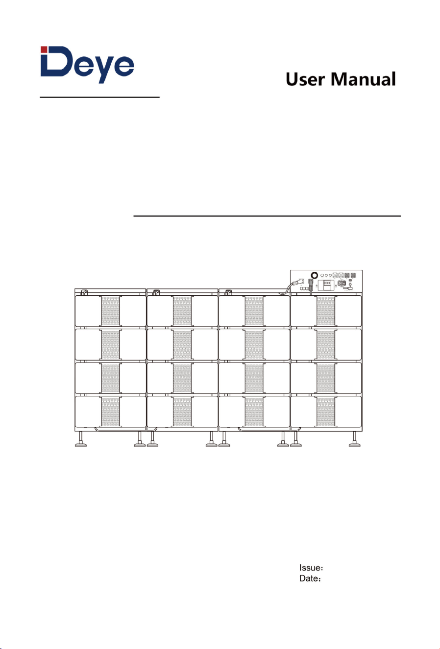
Lithium-ion Rechargeable Battery System
BOS-B Pro-A3
07
20260527

Preface
This manual provides information on safety, installation, electrical connection, operation,
maintenance, and other relevant aspects of the product.
In this manual, the terms “equipment”, “device”, and “product” refer to the product or its
components; the terms “manufacturer”, “producer”, and “the Company” refer to NINGBO
DEYE ESS TECHNOLOGY CO., LTD. (hereinafter referred to as the “Company”) or its authorized
agents.
The illustrations in this manual are for reference only and may differ from the actual
product. The Company reserves the right to modify the content without prior notice. For
the latest version, please visit our official website or contact our after-sales service.
The Company assumes no liability for any losses arising outside the scope of the warranty
policy.
Copyright
Copyright © 2026 NINGBO DEYE ESS TECHNOLOGY CO., LTD. All Rights Reserved.
No part of this manual may be reproduced, distributed, modified, or translated in any form
or by any means without the prior written permission of the Company.
Trademarks
All DEYE trademarks used in this manual in any form are the property of the Company.
Other trademarks, registered trademarks, logos or service marks mentioned in this
manual are the property of their respective owners.
Convention
Symbols Description
DANGER
Indicates an imminently hazardous situation which, if not avoided,
will result in death or serious injury.
WARNING
Indicates a potentially hazardous situation which, if not avoided,
could result in death or serious injury.
CAUTION
Indicates a potentially hazardous situation which, if not avoided,
could result in minor or moderate injury.
NOTE
Indicates supplementary explanation, clarification, or emphasis
on a particular content for better understanding.
NINGBO DEYE ESS TECHNOLOGY CO., LTD. hereby confirms that the products described in
this document comply with the fundamental requirements and other relevant provisions
of the applicable EU directives.
Technical Assistance
NINGBO DEYE ESS TECHNOLOGY CO., LTD
Add.: 6F No.8 building, No.568 Rixian South Road, Cixi Binhai Economic Development Zone,
Zhejiang, P. R. China.
Tel.: 0086 0574-63702591
E-mail: service-ess@deye.com.cn
Website: www.deyeess.com

Contents
1 Safety ................................................................................................................................................................................................................................... 1
1.1 Symbols .................................................................................................................................................................................................................. 1
1.2 Safety Precautions ................................................................................................................................................................................... 2
2 Product Introduction ........................................................................................................................................................................................ 7
2.1 Product Overview ...................................................................................................................................................................................... 7
2.2 Application Scenarios......................................................................................................................................................................... 7
2.3 Product Appearance .......................................................................................................................................................................... 8
3 Transportation....................................................................................................................................................................................................... 12
3.1 Transportation Precautions......................................................................................................................................................... 12
3.2 Transportation Methods ................................................................................................................................................................ 13
3.2.1 Handling ................................................................................................................................................................................................ 13
3.2.2 Forklift ..................................................................................................................................................................................................... 15
4 Installation ................................................................................................................................................................................................................. 16
4.1 Pre-Installation Preparation ........................................................................................................................................................ 16
4.1.1 Site Requirements ....................................................................................................................................................................... 16
4.1.2 Tool Requirements .................................................................................................................................................................... 19
4.2 Unpacking and Inspection ........................................................................................................................................................ 20
4.3 Installation Procedures ................................................................................................................................................................. 23
4.4 Post-Installation Inspection..................................................................................................................................................... 29
5 Electrical Connection .................................................................................................................................................................................. 30
5.1 Safety Precautions .............................................................................................................................................................................. 30
5.2 Preparation ................................................................................................................................................................................................ 30
5.2.1 Cable Preparation ................................................................................................................................................................... 30
5.2.2 Over-current Protection and Isolation Device ....................................................................................... 33
5.3 Cable Connection .............................................................................................................................................................................. 33
5.3.1 Grounding......................................................................................................................................................................................... 35
5.3.2 Power Cable ................................................................................................................................................................................. 35
5.3.3 Communication Cable .................................................................................................................................................... 35
5.3.4 Auxiliary Power Cable ........................................................................................................................................................ 36
5.4 Multi-System Connection .......................................................................................................................................................... 36
5.5 Post-Connection Inspection ................................................................................................................................................... 38
6 Operation .................................................................................................................................................................................................................. 39
6.1 Check Before Power-On ................................................................................................................................................................ 39
6.2 Power-On ..................................................................................................................................................................................................... 39
6.3 Power-Off ..................................................................................................................................................................................................... 39

7 Product Monitoring ........................................................................................................................................................................................... 41
7.1 DEYE Cloud Website .............................................................................................................................................................................. 41
7.2 DEYE Cloud APP ......................................................................................................................................................................................... 41
8 Maintenance and Storage .................................................................................................................................................................... 42
8.1 Safety Precautions .............................................................................................................................................................................. 42
8.2 Maintenance Schedule................................................................................................................................................................. 43
8.3 Post-Maintenance Requirements .................................................................................................................................... 44
8.4 Storage Precautions ........................................................................................................................................................................ 45
9 Product Specifications ................................................................................................................................................................................ 47
Appendix I Troubleshooting ...................................................................................................................................................................... 50
Appendix II Emergency Handling .......................................................................................................................................................... 61
1
1 Safety
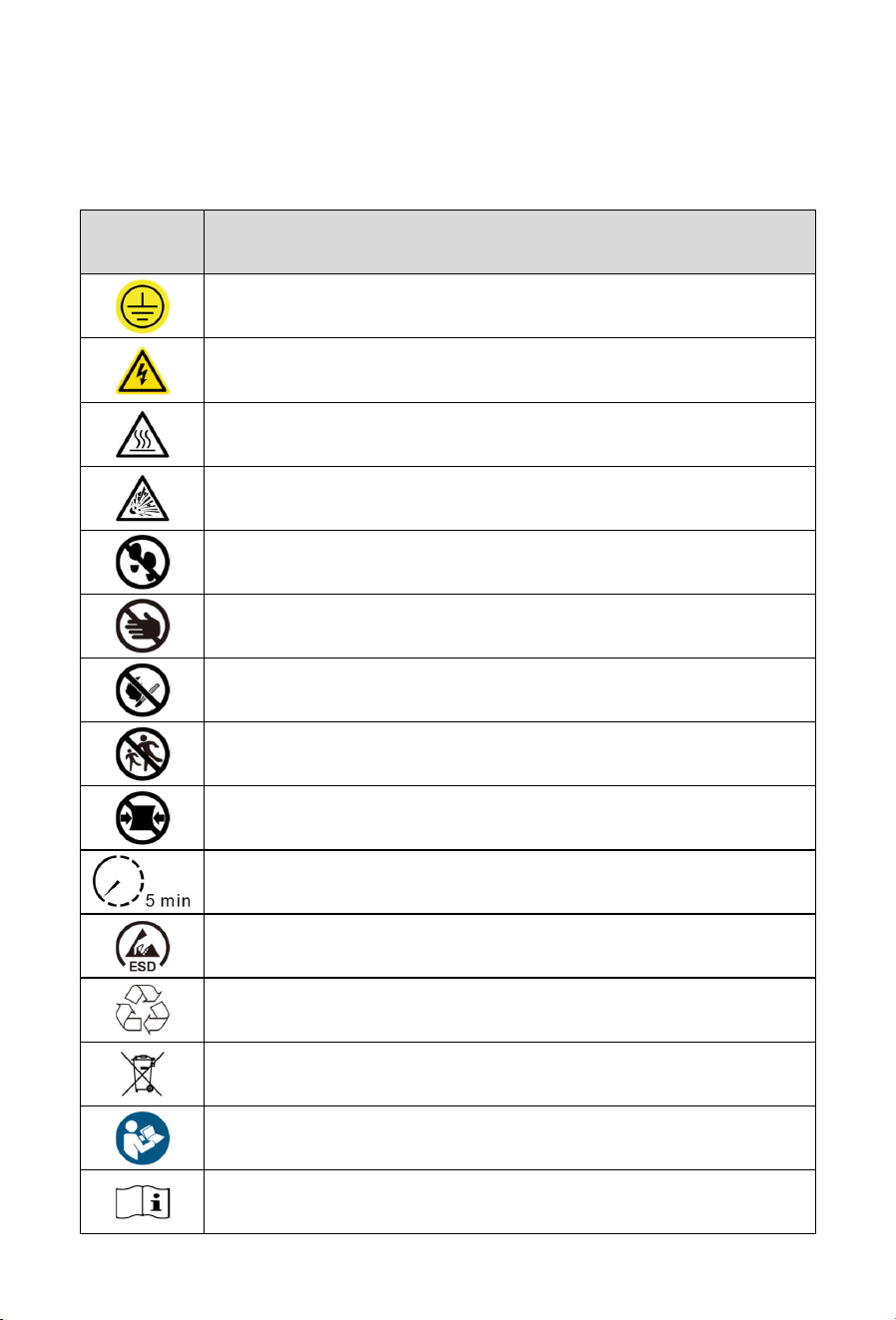
1.1 Symbols
Symbols Description
Connect an earth terminal to the ground.
Warning; Electricity.
Warning; Hot surface.
Warning; Explosive material.
Do not step on the product.
Do not touch with your hands. This is usually due to
being electrified, hot,
or being delicate and prone to damage.
Do not place the equipment near open flames or burn it. Do not use this
equipment near heaters or high-temperature sources.
No chasing.
The product / packaging is not
resistant to compression. Handle with
care to prevent internal damage.
5 min remaining before operation.
ESD protection area.
To indicate that the marked item or its material is part of a recovery or
recycling process.
Symbol for separate collection of batteries.
Refer to instruction manual/booklet.
Operator’s manual.
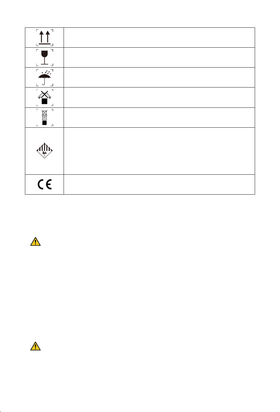
2
The package shall be kept upright during transportation and storage.
The package contains fragile objects and shall be handled with care.
The package shall be protected against rain, and rainproof measures
shall be taken during transportation and storage.
The package shall not be rolled during transportation.
Stacking limit by number
Lithium-ion battery transport falls under UN3480, Class 9 Miscellaneous
Dangerous Goods. For sea, land and air transportation, the battery is
classified into Packaging Group PI965 Section I. Class 9 Miscellaneous
Dangerous Goods labels and UN identification labels must be affixed
during transportation, and all operations shall be carried out in
accordance with relevant transport documents.
CE mark of conformity
1.2 Safety Precautions
Personal safety
DANGER
Operators must carefully read and comply with all safety information in this manual
and relevant document. Improper operation may cause casualties.
Keep the product out of reach of children and animals.
No one except DEYE staff or authorized personnel is allowed to open, repair or
disassemble the battery.
Only qualified professionals or trained personnel are permitted to install and
operate the equipment.
Only qualified professionals are permitted to remove safety facilities and inspect the
equipment.
WARNING
Personnel performing wiring operations on the equipment shall possess knowledge
of electronics, electrical wiring and mechanical expertise, and be familiar with the
electrical and mechanical schematics of this equipment.

3
In case of electrolyte contact with eyes or skin, flush thoroughly with clean water for
at least 10 minutes and seek immediate medical attention.
Only qualified personnel are permitted to service the battery. Unauthorized
operations void all liability.
CAUTION
Personnel operating this equipment shall understand and comply with the
requirements of this manual and other applicable documents.
Components may become extremely hot in case of malfunction; touching is
prohibited to prevent scalding.
Personnel planning to install and operate the equipment must master all necessary
safety precautions and local relevant standards.
This manual does not cover all conceivable scenarios; applicable standards and
relevant occupational health and safety regulations shall take precedence during
operation.
NOTE
Qualified professionals: Personnel who are familiar with the working principles and
structure of the equipment, have received training or have experience in equipment
operation, and are clear about the sources and degrees of various potential hazards
in equipment installation.
Trained personnel: Personnel who have received technical and safety training, have
the required experience, are aware of potential hazards to themselves during
certain operations, and can take protective measures to minimize hazards to
themselves and others.
Electrical Safety
DANGER
Lethal voltages exist inside the product. Touching the power grid and contact
points/terminals of equipment may cause electric shock.
Direct connection to AC power or PV solar wiring is strictly prohibited.
WARNING
Prior to installation, disconnect grid power and ensure the equipment is fully
powered off.
The battery may still be charged after power disconnection. Wait for 10 minutes and
use a standard voltmeter to confirm no voltage before operation.
4
The battery system must be well grounded with a grounding resistance of less than
1Ω.
Use insulated tools and gloves during operation, and remove metal accessories
such as watches and rings.
Prevent terminals from contacting exposed wires or metal objects.
Do not place any tools or metal parts on the battery module or PDU.
Adjacent live parts shall be covered or shielded.
CAUTION
Ensure correct wiring. Distinguish positive and negative poles strictly to prevent short
circuits with external devices.
Do not use faulty or incompatible power conversion unit.
Verify that battery system parameters are fully compatible with connected
equipment.
Mechanical Safety
DANGER
Installation or operation of the battery system in explosive or high-humidity areas is
strictly prohibited.
WARNING
Do not insert foreign objects into any part of the battery.
Place necessary warning signs or barriers near the product to prevent accidents
caused by misuse or unrelated persons.
CAUTION
Do not expose cables outside the designated routing.
NOTE
Unpack and inspect immediately. Contact your vendor if damaged or parts are
missing.
Maintain a State of Charge (SOC) above 5% during use. Recharge within 48 hours
after full discharge to avoid over-discharging.
Contact the supplier within 24 hours if any abnormality occurs to the battery.
Maintenance Safety
5
DANGER
Disassembling, modifying, or opening the battery is strictly prohibited.
WARNING
Power off the battery completely before moving or performing any maintenance.
All battery terminals and circuit connectors must be disconnected during
maintenance.
Maintenance shall follow the principles: power off, prevent restart, verify no voltage,
grounding and short-circuit protection, shield adjacent live parts.
Residual safety risks may arise from failure to observe warnings, improper
installation, or construction by untrained personnel.
NOTE
Do not paint any internal or external components of the battery.
Do not clean batteries with cleaning solvents.
Commissioning of the battery energy storage system shall be completed no later
than six months after delivery.
Environmental Safety
DANGER
Do not expose the battery to fire, heaters, high-temperature sources, or open flames.
In case of fire, use only dry chemical fire extinguishers. Liquid extinguishers are
forbidden.
Damaged or failed batteries may leak electrolyte, producing hydrofluoric acid and
other substances, causing chemical burns.
WARNING
Do not expose the battery to flammable substances, harsh chemicals, or their
vapors.
Do not submerge the battery in water or expose it to moisture when incomplete. (The
product’s protection rating is valid exclusively when the product is in its complete,
fully assembled configuration.)
Disposal Safety
WARNING

6
Immediately cease use of damaged, swollen, or leaking batteries.
Do not attempt to repair or disassemble damaged batteries. Contact your installer,
sales partner, or a qualified recycling service provider for safe handling and disposal.
Ensure damaged batteries are stored in a dry, cool environment, protected from
moisture and direct sunlight.
CAUTION
Waste batteries may contain hazardous pollutants and heavy metals. Improper
storage, handling, or disposal can:
Pose risks to human health.
Cause environmental pollution (soil, water, and air contamination)
In severe cases (e.g., damaged lithium-ion batteries), lead to leakage, fire, or
explosion.
NOTE
Used batteries must not be disposed of as household or domestic waste. You are
legally obligated to:
Remove any privacy-related information from the product before disposal.
Return used batteries and rechargeable batteries to designated or authorized
collection/recovery points in compliance with local regulations and standards for
waste battery management.
Batteries contain valuable raw materials (e.g., lithium, iron, cobalt, nickel) that can
be recycled and reused. Proper disposal supports resource conservation and
circular economy goals.
7
2 Product Introduction
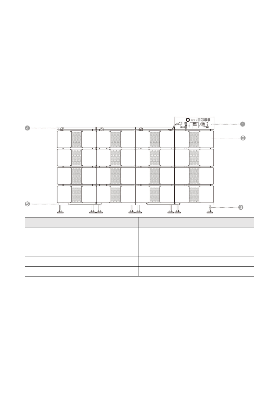
The Deye BOS-B Pro-A3 is a high-voltage energy storage system designed for small
commercial and industrial energy storage scenarios. It covers a capacity range of 80–257
kWh, meeting power and capacity requirements for a wide range of application scenarios.
In this system, the first three digits of the battery pack SN code are 261, and the first three
digits of the PDU SN code are 293.
2.1 Product Overview
N
o.
Item
1
PDU (Power Distribution Unit)
2
B
attery
P
ack
(
Optional:
5~16 pcs
)
3
Leveling Foot
4
Top Cover
5
Base
2.2 Application Scenarios
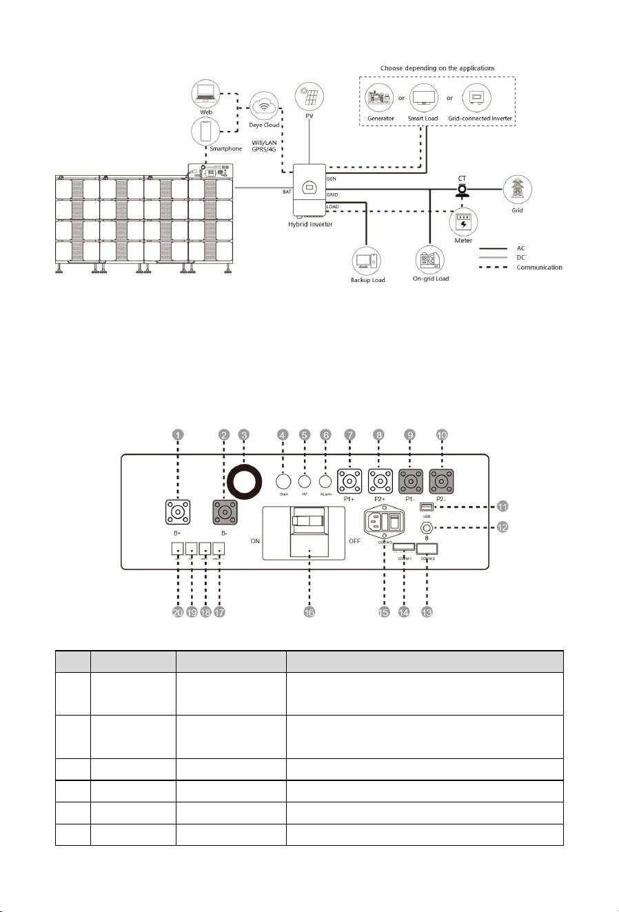
The following illustration shows basic application of this battery system. It also includes
following devices to have a complete running system:
Generator or Utility;
PV modules;
Power Conversion Unit (Charge & Discharge).
Consult with your system integrator for other possible system architectures depending on
your requirements.
8
The picture is only a reference picture, please refer to the actual product, the final
interpretation right belongs to DEYE.
2.3 Product Appearance
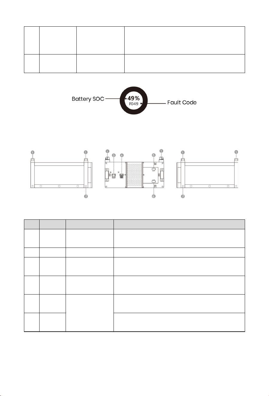
PDU: BOS-B-PDU-2-A
Front View
No.
Icon
I
tem
Description
1 B+
Positive
Terminal
Positive connection terminal for battery.
2 B-
Negative
Terminal
Negative connection terminal for battery.
3
/
Display
Screen
Displays system SOC
values and fault codes.
4
Start
Start Button
12 VDC internal power start switch for the PDU
5
HV
HV indicator
High
-
voltage
hazard
indicator (Yellow)
6
Alarm
Alarm indicator
Battery system alarm indicator (Red)

9
7 P1+
Positive
Terminal
1
Terminal for
the first Power Conversion Unit
positive connection
8 P2+
Positive
Terminal 2
Terminal for the second Power Conversion
Unit positive connection
9 P1-
Negative
Terminal
1
Terminal for the first Power Conversion Unit
negative connection
10 P2-
Negative
Terminal
2
Terminal for the second Power Conversion
Unit negative connection
11 USB USB Port
BMS upgrade port and storage expansion
port
12
Bluetooth Wireless connection port for mobile APP
13 COMM2
Communication
port
Communication port for the first battery
module; provides 12 VDC power supply to the
first battery module
14 COMM1
RS485
communication
interface
RS485 communication interface &
emergency power-off trigger interface
15 COMM3
Multi-function
interface
COMM3 is a multi-
function interface
integrating power input, fuse protection, and
a power switch. It features a 10A/250V~
standard power socket, a 250V-
only fuse
holder for overcurrent protection, and a slide
switch to control power supply.
This
port must be connected to the power
supply of 3A, 50-
60Hz, 200~240V when this
equipment is in use, otherwise the fan cannot
rotate normally.
16 ON/OFF
DC circuit
breaker
Manual switch for connecting / disconnecting
the battery
stack
and external devices.
17 HVBOUT OUT COM
Communication output port for connection
with the next BOS-B-PDU-2-
A communication
input.
18 HVBIN IN COM
Communication input port for connection
with the previous BOS-B-PDU-2-
A
communication output.
10
19 PCS PCS COM
PCS battery communication terminal; used to
transmit battery data to the
Power
Conversion Unit
.
20 LAN Ethernet
Standard RJ45 Ethernet port. Customizable for
different needs.
PDU: Display Screen
For the detailed fault codes, refer to Appendix I Troubleshooting.
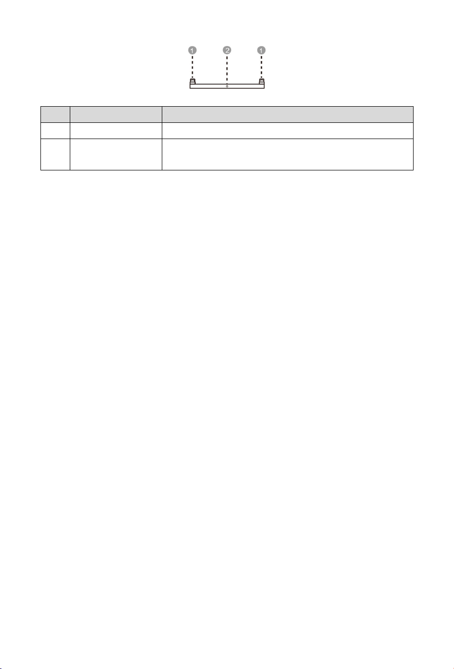
Battery Pack: BOS-B-Pack16-AX (X=1, 3, 4...)
Left View
Front View
Right View
No.
I
con
I
tem
Description
1 / Guide Block
Aligning the upper assembly with this battery
module.
2
/
Mounting Hole
/
3 B+
Positive
Terminal
Battery module positive terminal
4 B-
Negative
Terminal
Battery module positive terminal
5 COMM1
Low-voltage
C
ommunication
Port
Battery module communication and power
supply input
/
output interface
6 COMM2
Battery module communication and power
supply input/output interface
Base
11
Front View
No.
I
tem
Description
1
Guide Block
Aligning the upper assembly with this
base.
2
Protective
Grounding
Safety grounding terminal, ensuring reliable grounding of
the metal enclosure to prevent electric shock risks

12
3 Transportation
3.1 Transportation Precautions
DANGER
Transportation of end-of-life, damaged or recalled batteries may be prohibited in
some regions. Confirm local regulations before transportation; illegal transportation
is strictly prohibited.
It is strictly prohibited to mix dangerous goods with food, medicine, animal feed and
their additives in the same vehicle or container, and to transport with sharp objects
in the same vehicle or container.
WARNING
Lithium-ion batteries are classified as UN3480, Class 9 Miscellaneous Dangerous
Goods. For sea, land and air transportation, they fall under PI965 Section I. Class 9
dangerous goods labels and UN identification labels must be affixed during
transportation.
Transportation and storage service providers must hold the dangerous goods
operation certification required by local laws and standards; no relevant business
shall be undertaken without corresponding qualifications.
Sea transportation shall comply with the requirements of the International Maritime
Dangerous Goods Code (IMDG Code), and land transportation shall meet ADR or JT/T
617 transport standards; illegal selection of transport modes is strictly prohibited.
If the battery has peculiar smell, leakage, smoke, fire or any other abnormalities
before transportation, transportation is strictly prohibited.
Obtain MSDS certification before sea transportation, seal the external gaps of
containers and affix marks certified by the classification society; equip the outer
packaging with rainproof canvas covers to avoid paint film scratches.
Remove obstacles along the transport route, confirm that transport
vehicles/containers meet dangerous goods transport standards, and ensure
dangerous goods transport vehicles are equipped with two tested CO₂ fire
extinguishers.
Before removing the transport protector, check whether the packaging is damaged
and whether the impact indicator on the outer packaging of the battery converter
is triggered; if triggered, the risk of transport damage cannot be ruled out.
When transporting faulty batteries, avoid flammable and explosive material storage

13
areas, residential areas, mass transit facilities, elevators and other densely
populated places.
CAUTION
During the whole transportation process, strictly prevent severe vibration, impact
and extrusion, avoid direct sunlight, rain and moisture, and take rainproof, moisture-
proof and sun-protection measures.
Smoking is strictly prohibited in transportation, loading and unloading areas. Freight
personnel are not allowed to open the outer packaging of battery packs without
permission; handle with care during moving to prevent bumping.
Transport operators must wear protective gloves and toe-cap safety shoes for
personal protection, and pay special attention to avoiding scratches by sharp metal
panels and crushing injuries by heavy objects.
NOTE
All operations must be completed by professionally trained personnel, and
unauthorized operation by non-professionals is strictly prohibited.
Complete compliant and accurate declaration before transportation, and carefully
check whether the battery packaging, labels and markings are intact.
Transport vehicles/containers must meet dangerous goods transport standards to
ensure the product is firmly fixed throughout the transportation process.
Do not remove the product transport packaging before arrival at the installation site;
remove it after arrival.
3.2 Transportation Methods
3.2.1 Handling
DANGER
A single battery pack is heavy; forcible single-person handling is strictly prohibited.
Battery packs/stacks are top-heavy; side placement, upside-down placement and
unfixed transportation are strictly prohibited; measures must be taken to prevent
tipping during vertical transportation.
Before handling:
Confirm that all personnel are in good physical condition before handling, wear anti-
slip gloves, anti-slip shoes and necessary waist protection equipment to avoid injuries.
Clean the handling path in advance to ensure a safe ground; slow down on slopes with
special personnel assistance, and reserve sufficient operating space in narrow areas.
When assigning carriers, the number of personnel shall be reasonably determined in

14
accordance with the “Recommended Limits for Single Lifts by Healthy Adult Workers”
specified in ISO 11228-1:2003 (25kg for males, 15kg for females), combined with the
requirements for handling stability, load distribution and safety redundancy.
Example (for a 100kg product):
Short-distance handling on flat ground: at least 4 personnel working in coordination;
Long-distance handling, moving up/down slopes, operating in narrow spaces or
lifting/lowering: no less than 5 personnel are recommended.
Wear personal protective equipment such as protective gloves and safety shoes when
manually moving the equipment.
When handling:
When manually lifting an object, move close to it, squat down, and lift smoothly and
steadily using leg strength instead of back strength. Do not jerk or twist your body
during lifting.
Move or lift the equipment only by its designated handles or lower edges. Do not hold
the handles of modules installed inside the equipment.
Do not rapidly lift heavy objects above waist height. Place the object on a waist-height
workbench or other suitable surface, reposition your hands, and then continue lifting.
Move heavy objects smoothly, with balanced force and at a slow, constant speed.
Lower the object gently and steadily to avoid collisions, drops, scratches, or damage to
components and cables.
When moving heavy objects, pay attention to workbenches, slopes, stairs, and slippery
areas. When moving through a doorway, ensure the opening is sufficiently wide to
prevent impact or injury.
When carrying heavy objects, turn by moving your feet instead of twisting your waist.
When lifting and carrying, keep your feet pointing toward the intended direction of
movement.
After handling:
After handling, confirm that the load is placed stably to avoid injury caused by tipping.
15
3.2.2 Forklift
DANGER
During forklift operation, unrelated personnel must keep at least a 2m safe distance;
standing or riding on the forklift or cargo is strictly prohibited.
Overloading and lifting loads too high are strictly prohibited to avoid forklift
instability and rollover risks.
Only certified professional forklift operators may perform operations; unauthorized
operation by non-professionals is forbidden. Strictly follow all clauses; violators bear
full responsibility for equipment damage and personal accidents.
Equipment Parameter Requirements:
Item
Requirements
Rated load
capacity
more than 2 times of product weight
Fork length
no less than product width
Fork width
80mm~160mm
Fork thickness
25mm~70mm
Forklift lifting height
Subject to actual on
-
site installation
Driving & Steering:
Driving speed shall be strictly controlled below 3 miles per hour (3mph). Sharp turns are
strictly prohibited to avoid cargo shaking and imbalance.
Before reversing, the forklift operator must carefully check the rear area and confirm
safety before reversing. When reversing in confined spaces, a special commander
must be arranged to guide the operator throughout the process.
Operating forklifts on slopes with a gradient ≥5° is strictly prohibited. Slow down and
operate carefully when lifting loads on uneven roads.
Tilting or inverting the product is strictly prohibited during the whole transfer process. If
tilting or inversion is necessary under special circumstances, restore the product to
upright position as soon as possible, and leave it standing for 2 hours before power-on.
16
4 Installation
DANGER
There is a risk of static overload during the entire installation process, which may
cause damage to building structures. Be sure to verify the site bearing capacity and
anti-static measures in advance.
CAUTION
Only qualified professionals or trained personnel are permitted to install the
equipment.
Personnel planning to install the equipment must master all necessary safety
precautions and local relevant standards.
Only qualified professionals are permitted to remove safety facilities and inspect the
equipment.
Personnel installing this equipment shall understand and comply with the
requirements of this manual and other applicable documents.
WARNING
Product assembly must be carried out in strict accordance with the design scheme,
process requirements, relevant regulations and national standards; unauthorized
changes to assembly procedures and technical parameters are strictly prohibited.
4.1 Pre-Installation Preparation
4.1.1 Site Requirements
DANGER
Do not expose the equipment to flammable or explosive gases, smoke, or heat/fire
sources, and do not operate the equipment in such environments. Do not store any
flammable or explosive materials around the equipment, and do not cover or wrap
the battery. Otherwise, it may cause serious safety accidents such as fire, explosion,
or equipment damage.
The product should in principle be installed at least 15 ft (4.57 m) away from heat
sources. This distance may be reduced by 100 cm if a fire barrier or other equivalent
protective measure is provided.
Each battery pack requires ventilation of 112.6 m³/h. Total ventilation demand = 112.6
× number of packs. The installation space shall achieve minimum one air change

17
per minute or the calculated total ventilation volume, whichever is larger.
WARNING
Install the equipment in an area far away from liquids. Do not install it in areas prone
to condensation, such as under water pipes and air exhaust vents, or areas prone
to water leakage, such as air conditioner vents, ventilation vents, or feeder windows
of the equipment room. Ensure that no liquid enters the equipment to prevent faults
or short circuits.
To prevent damage or fire due to high temperature, ensure that the ventilation vents
or heat dissipation systems are not obstructed or covered by other objects while the
equipment is running, so as to ensure unobstructed heat dissipation.
The product poses a risk of burns. Do not touch hot surfaces to avoid personal injury.
Keep away from the air outlet of the product to prevent personal injury caused by
high-temperature air flow.
NOTE
The installation and usage environment must meet the requirements of relevant
international standards and local laws and regulations. The user is obliged to take
measures to protect the equipment against fire or other hazards.
Confirm that the installation site has sufficient bearing capacity in advance
according to the total weight of the battery storage system; installation in areas with
unqualified bearing capacity is strictly prohibited.
When selecting the installation site, plan a reasonable equipment transportation
route in advance, remove obstacles, debris and dust on the site to ensure a spacious
and unobstructed working space.
Keep the equipment out of the reach of children and away from daily working or
living areas, including but not limited to the following areas: studio, bedroom, lounge,
living room, music room, kitchen, game room, home theater, sunroom, toilet,
bathroom, laundry room, and attic.
Do not install the equipment in enclosed, poorly ventilated areas without proper fire-
fighting facilities, or in areas difficult for firefighters to access, to prevent failure to
dispose of fires in a timely manner.
Do not install the equipment on a moving object, such as a ship, train, or car, to avoid
damage or potential safety hazards caused by jolting and shaking of the equipment.
Ensure that the equipment is installed in a clean, dry and well-ventilated area with
proper temperature, humidity and altitude range. For more data, please check the
"Technical Specifications" section. It is recommended that the installation site have
an altitude no higher than 3000 meters (an increase in altitude will reduce the

18
battery output power)
Do not install the equipment in an environment with magnetic dust, volatile or
corrosive gases, infrared and other radiations, organic solvents, conductive metals,
or salty air, so as to avoid damaging equipment components. (This product, with
Anti-Corrosion Level C3, is only suitable for installation beyond 5 km from the
coastline.)
Do not install the equipment in an area conducive to the growth of microorganisms
such as fungi or mildew, to prevent microorganisms from eroding the equipment
and affecting its normal operation and service life.
Do not install the equipment in an area with strong vibration, noise, or
electromagnetic interference, to avoid affecting the operational stability and safety
of the equipment.
Do not install the equipment in a position that may be submerged in water, to
prevent short circuits, damage or safety accidents caused by water entering the
equipment.
The floor and wall at the installation location shall be fully waterproof with a flat and
level surface, to avoid affecting the installation and operation of the equipment due
to uneven ground or water leakage.
The equipment should be placed on a surface with sufficient load-bearing capacity.
The installation site shall adopt solid brick-concrete structures, concrete walls and
floors. If other types of walls or floors are used, they must be constructed of flame-
retardant materials and meet the load-bearing requirements of the equipment.
Before installing and powering up the system, dust and iron filings must be removed
to keep the environment clean. The system cannot be installed in desert areas
without a shell to protect against sand.
The product shall be installed at a location where the impact of its noise is minimized.
This product may be installed indoors.
Recommended Clearance
During product installation, the following clearance requirements shall be met between
the product and surrounding buildings and objects:
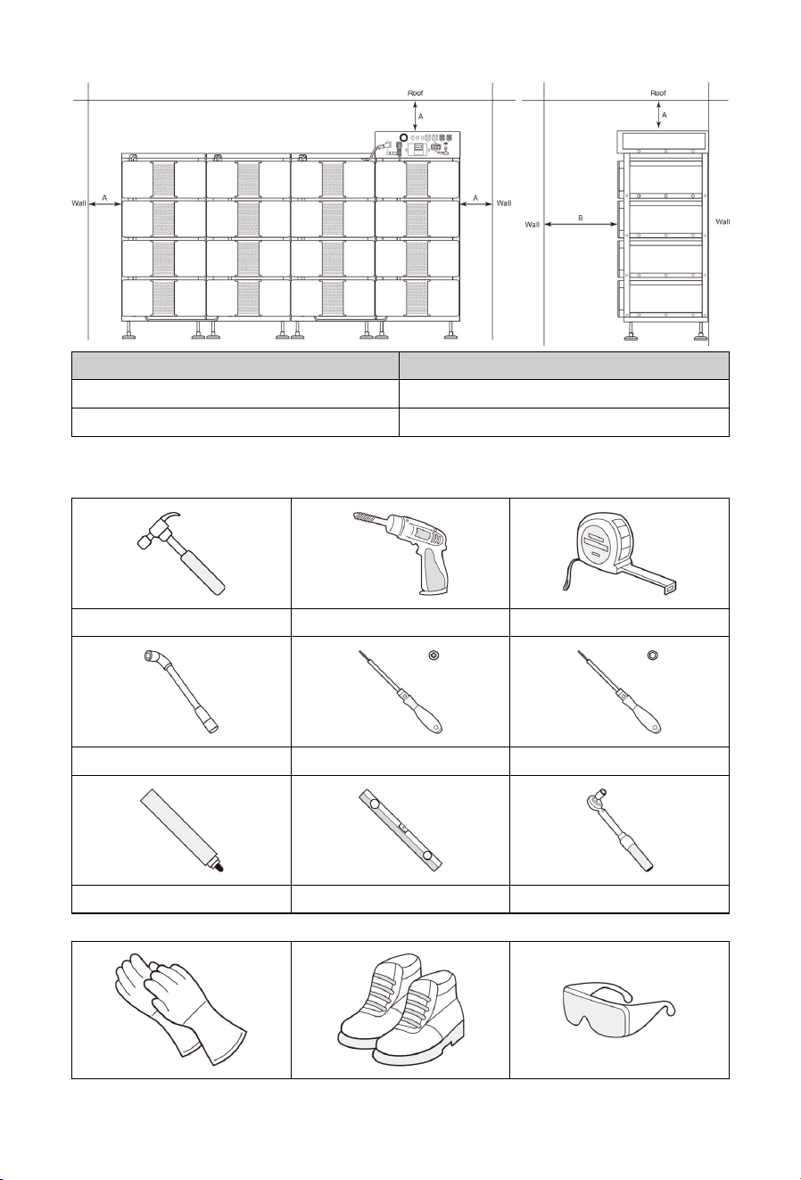
19
Item
Distance (mm)
A
1
00
B
100
0
4.1.2 Tool Requirements
These tools are required to install the device.
Hammer
Drill
Tape measure
Hexagon socket wrench
Phillips screwdriver
Hex screwdriver
Marker
Precision Level
T
orque wrench
It is recommended to wear the following safety gear when installing the device.

20
Insulated gloves
Safety shoes
Safety goggles
4.2 Unpacking and Inspection
If possible, do not remove the transport packaging until the equipment arrives at the
installation site.
After preparing the equipment for installation, unpack it carefully to avoid scratching
the equipment.
This product is mostly packaged with shock-resistant and easy-to-disassemble EPE
foam, which can be unpacked with tools such as cutters or knives.
Keep the equipment stable during unpacking.
If the installation environment is not conducive to equipment protection, take
measures to prevent internal battery failure caused by condensation or dust
corrosion (e.g., cover with woven cloth or dust cover).
After unpacking the equipment, check that the deliverable contents are intact and
complete, and free from any damage. If any items listed in the Packing List is missing
or damaged, contact your dealer or our after-sales service team.
All components shall be thoroughly cleaned prior to assembly to ensure surfaces
are free of dirt and impurities.
During component handling and storage, collision and scratch are strictly
prohibited. Take moisture-proof and rust-proof measures to avoid appearance
damage and performance failure of components.
This product is heavy. Handle it with care when taking it out of the packaging box;
rough handling is strictly prohibited to avoid personnel injuries and equipment
falling damage.
When connecting to Power Conversion Units or operating in parallel mode, only
standard cables included in the unpacking list must be used. If other cables are
required under special circumstances, ensure they meet relevant standards.
Packing List
Battery pack box
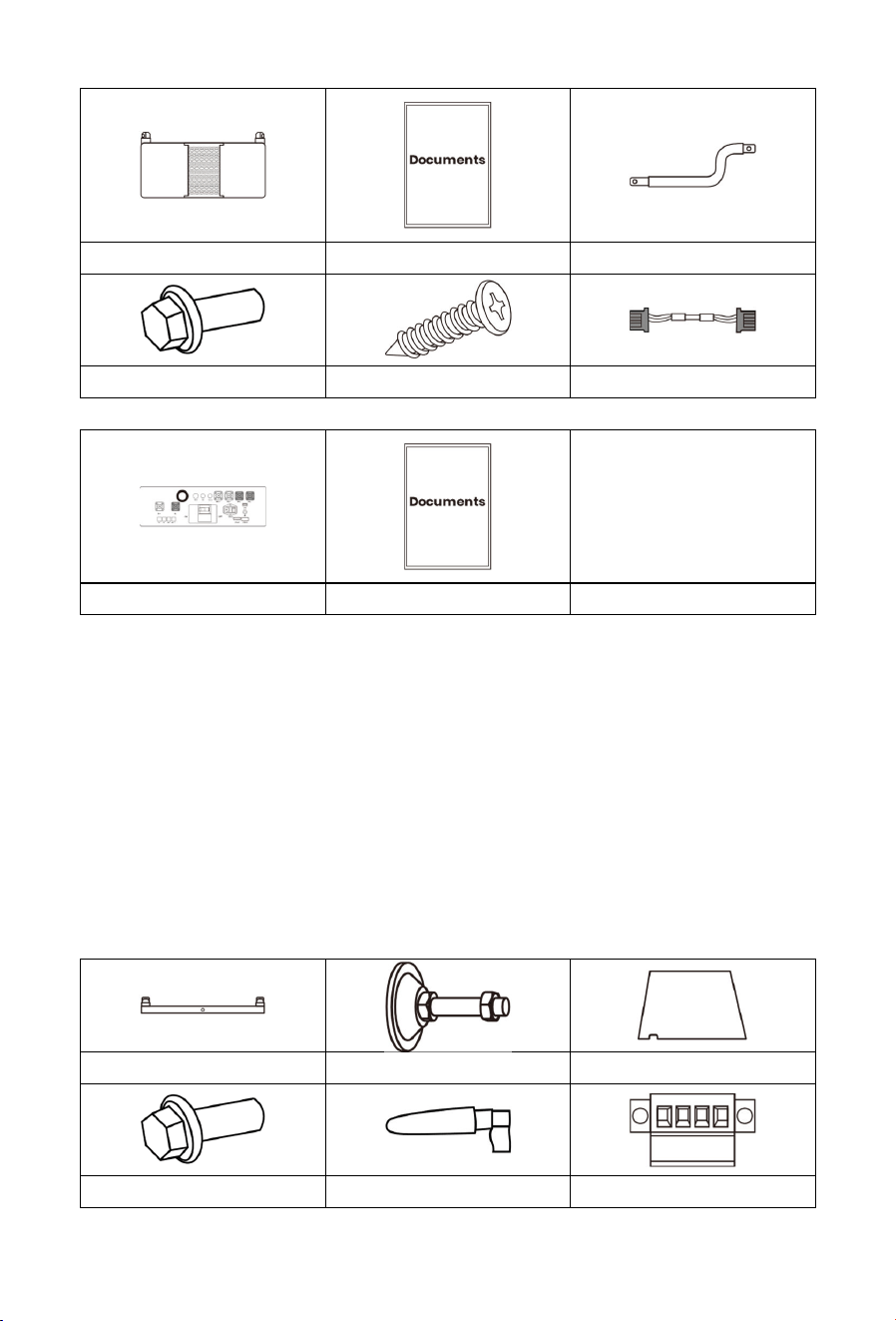
21
Battery
P
ack *1
Documents
Copper bar
*1
M5*14
Bolt
*4
M3*6
Bolt
*
4
Communication
C
able
*1
PDU box
P
DU *1
Documents
Base box
The Base box includes standard parts and inverter-specific parts for connection with
different inverter/PCS models.
Accessory Kit:
BOS-B-AP-A: Packing List 1 + Packing List 2
BOS-B-AP-B: Packing List 1 + Packing List 3
NOTE
BOS-B-AP-A is compatible with 100/125KW Power Conversion Unit (SUN-100K-PCS01HP3,
SUN-125K-PCS01HP3), while BOS-B-AP-B is compatible with 80KW Power Conversion Unit
(SUN-80K-SG02HP3-EU-EM6).
Packing list 1
Base *4
Leveling Foot
*16
Top Cover *3
M
5*14
Bolt
*24
4G External Antenna *1
Emergency
P
ower
-
off
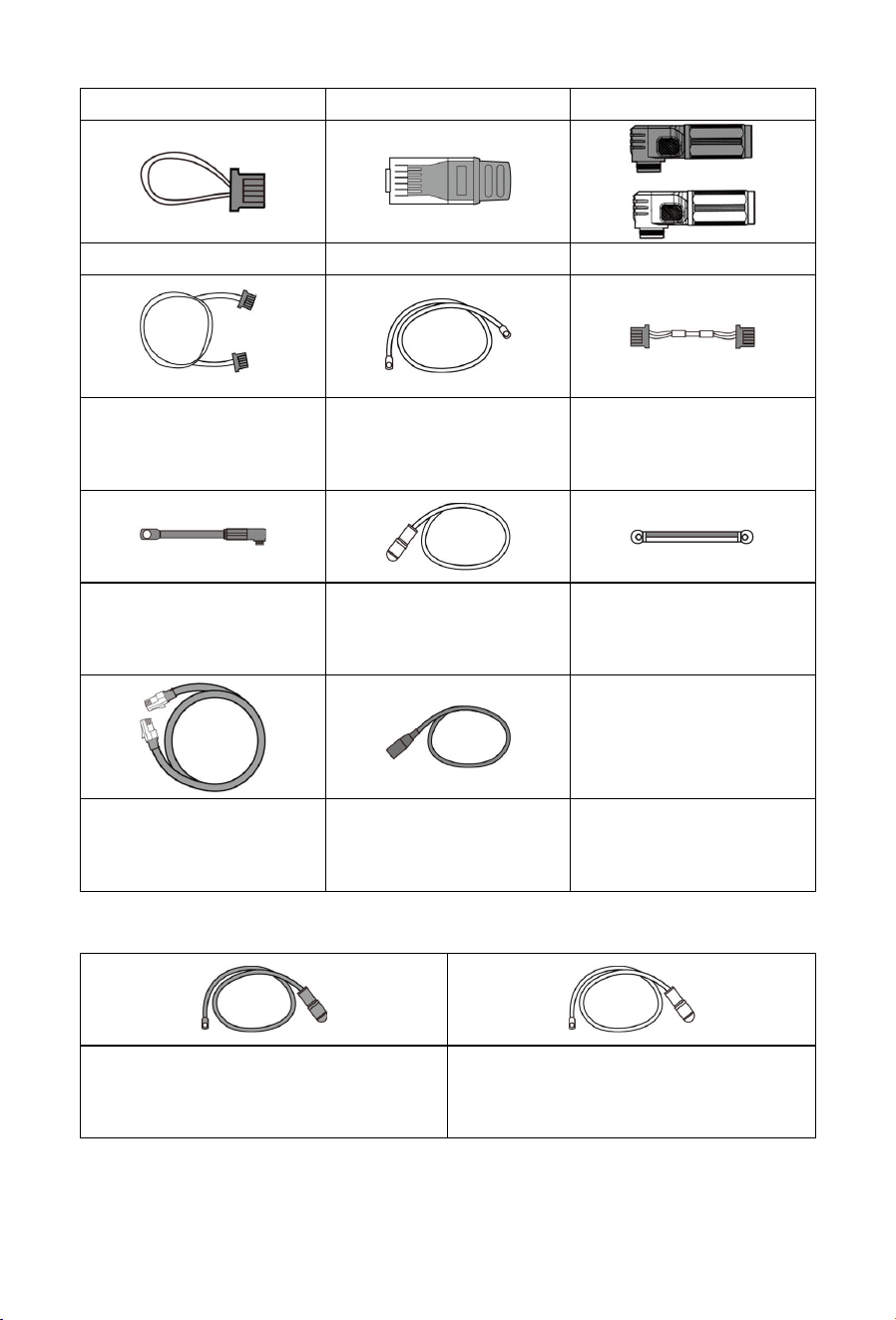
22
I
nterface
*1
T
erminal resistor A
*1
T
erminal resistor B
*1
ESS
Connector
×
1 set
Communication Cable *3
(For Battery Stacks
Connection)
Power Cable *3
(For Battery Stacks
Connection)
Communication Cable *1
(For Connecting PDU to
Battery Pack
)
Negative Power Cable *1
(For Connecting PDU to
Battery Pack
)
Positive Power Cable *1
(For Connecting PDU to
Battery Pack
)
Ground Wire *4
Communication Cable *1
(For Connecting PDU to
Power
Conversion Unit)
Auxiliary Power Supply
Cable *1
Packing list 2
For 100/125KW Power Conversion Unit (SUN-100K-PCS01HP3, SUN-125K-PCS01HP3)
Negative Power Cable *1
(For Connecting PDU to Power
Conversion Unit)
Negative Power Cable *1
(For Connecting PDU to Power
Conversion Unit)
Packing list 3
For 80KW Power Conversion Unit (SUN-80K-SG02HP3-EU-EM6)
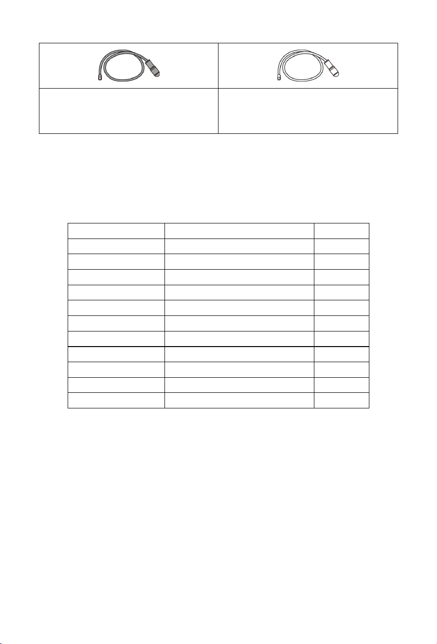
23
Negative Power Cable *2
(For Connecting PDU to Power
Conversion Unit)
Positive Power Cable *2
(For Connecting PDU to Power
Conversion Unit
)
Recommended Torque
Applicable for: sheet metal parts (Battery pack cabinet assembly / Sheet metal fixing /
Bracket connection/...)
Note: ① Strictly follow the recommended torque, avoid over-tightening/under-
tightening ② Unit: N·m (Newton meters)
Bolt Specification
Recommended Torque
Unit
M3
0.7
~
0.9
N·m
M4
1.6
~
2.2
N·m
M5
3.2
~
4.4
N·m
M6
5.3
~
7.4
N·m
M8
12
~
19
N·m
M10
25
~
38
N·m
M12
44
~
65
N·m
M14
54
~
108
N·m
M16
110
~
165
N·m
M18
150
~
240
N·m
M20
216
~
335
N·m
Supplementary Instructions
① The torque value is for reference only for standard bolts during normal assembly;
adjust appropriately for special working conditions (high vibration/harsh environment).
② Use a calibrated torque wrench for installation to ensure torque accuracy.
4.3 Installation Procedures
NOTE
Before installation, be sure to turn the manual switch of the components of the
product to the OFF position; live operation is strictly prohibited.
This product is heavy. If a forklift is used for handling and installation, ensure
cooperative operation by multiple personnel to prevent tipping or falling.
The maximum allowable stacking height for a single stack of battery packs is 4
24
layers.
All screws and expansion bolts must be tightened to ensure firm connection.
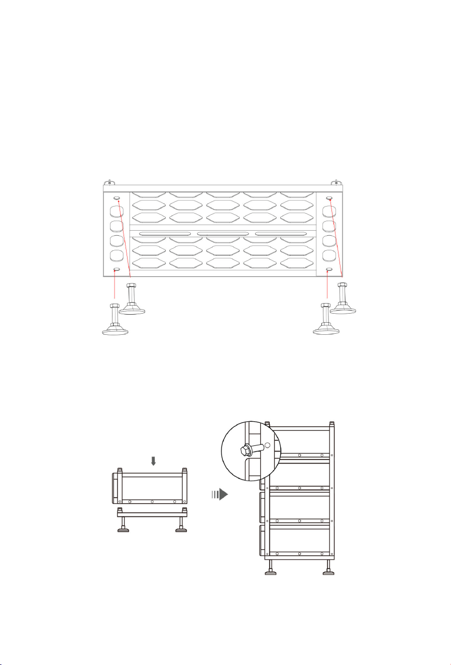
Step 1:
Take out the 4 bases, screw the 4 leveling feet into each base clockwise, and rotate
them for preliminary height adjustment.
Then check and fine-tune the levelness of the assembly with a precision level. After
confirming the surface is horizontal, fix the leveling feet in place.
Place the bases on a level and solid surface.
Step 2:
Install the battery packs one by one in a stacked manner.
After stacking, fasten the battery pack with 4 M5*14 Bolt (2 on each side).
Recommended torque: 3.2~4.4 N·m.
NOTE
The 2 or 3 or 4 battery stacks can only be arranged successively on the left side of
25
the first stack.
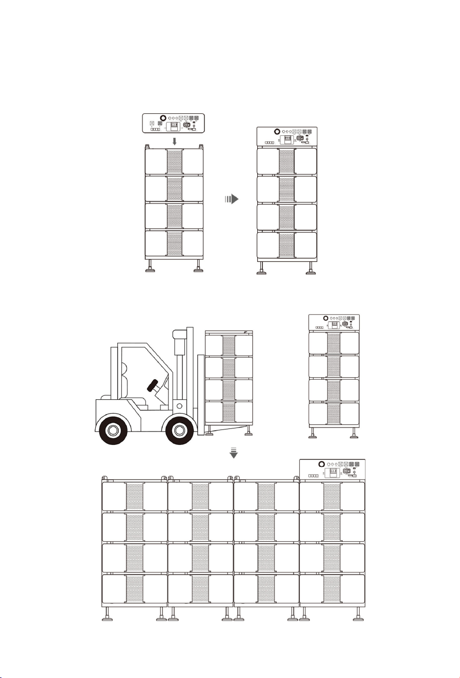
Step 3:
Mount the PDU on the top battery pack of the first stack using 4 M5*14 Bolt (2 on each
side). Recommended torque: 3.2~4.4 N·m.
Step 4:
Use a forklift to move the 2
nd
, 3
rd
, and 4
th
stacks to the left of the first stack.
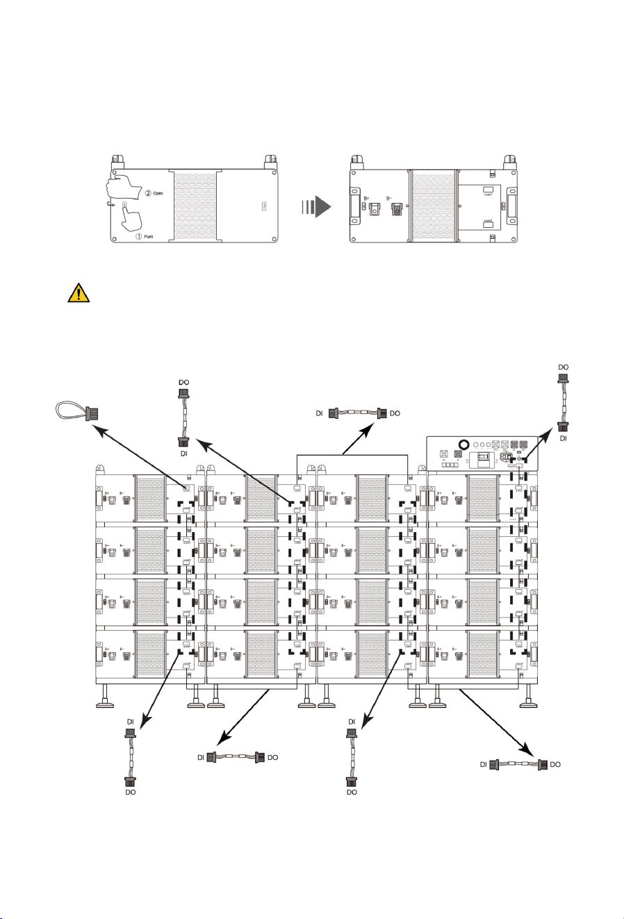
26
Step 5:
Apply force to the front panel by pressing the “PUSH” until its edges lift up. Grip the
edge of the front panel and pull it open to the desired angle as needed.
Open the front panel on the right side of the battery pack using the same method.
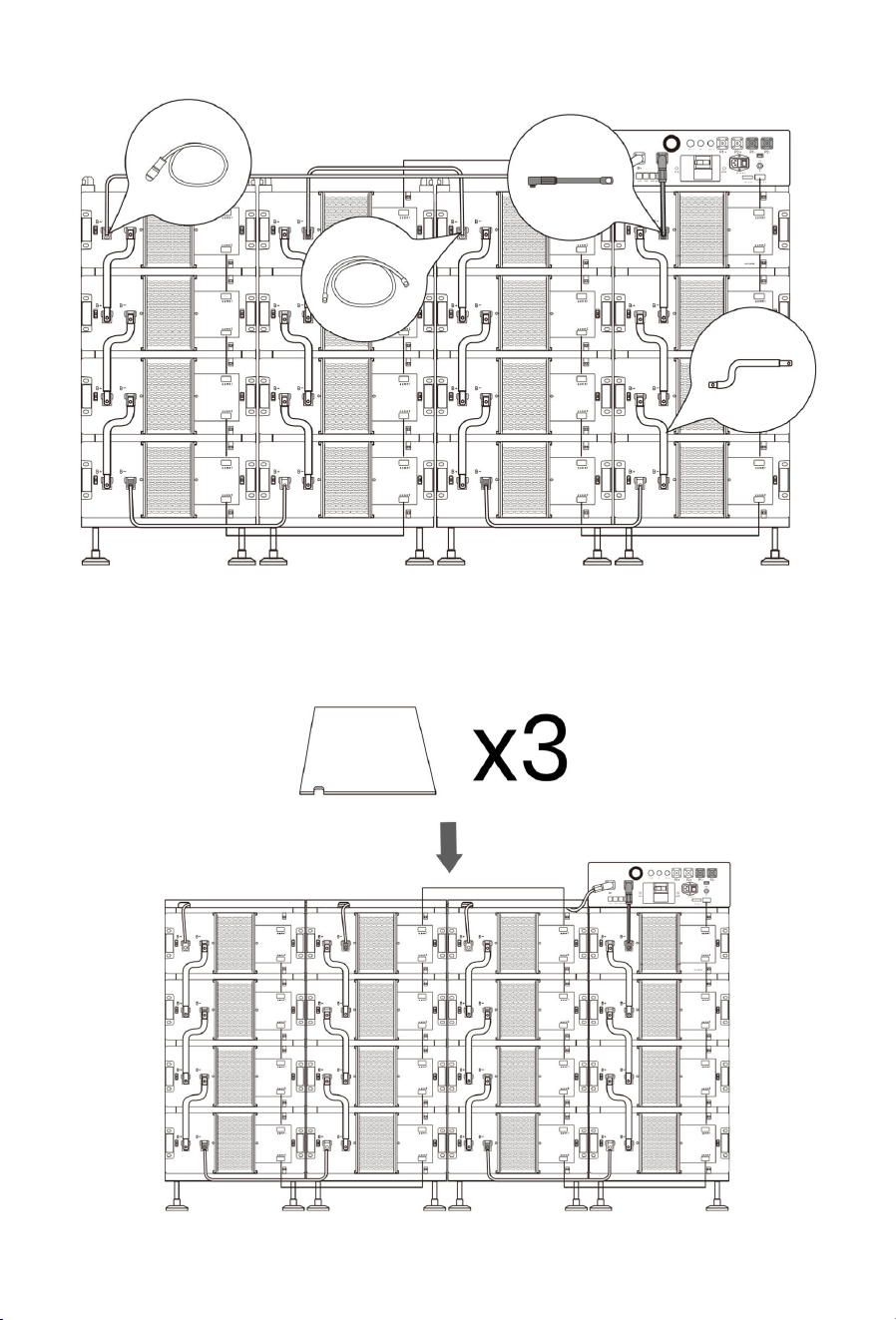
Step 6:
CAUTION: PAY ATTENTION TO THE DIRECTION OF THE CABLES
Perform communication cable connection. (Insert Terminal resistor A into the
comm1 port of the last battery pack.)
Perform power cable connection and copper bar connection
27
Step 7:
Put the top cover on the top battery pack of the 2
nd
, 3
rd
, and 4
th
stacks.
Lock the outermost top cover with 2 M5*14 Bolts on the outer side. Recommended
torque: 3.2~4.4 N·m.
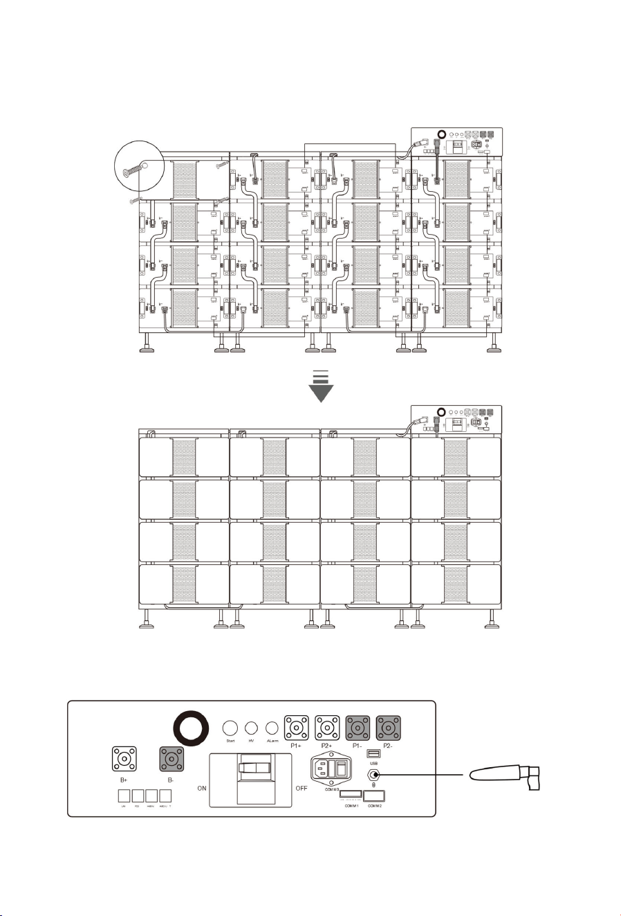
28
Step 8:
Secure the front panel of every battery pack using 4 M3*6 Bolts. Recommended
torque: 0.7~0.9 N·m.
Step 9:
Screw the 4G External Antenna from the Base box clockwise into the position shown
in the diagram and tighten firmly to ensure it does not come loose.

29
4.4 Post-Installation Inspection
Item
Inspection Criteria
The system/battery pack
Intact without deformation, collision or
scratch.
B
ase protective cover
Intact and effective.
Bracket, base and bolts
Tightened and firmly installed.
Grounding marking
Clear
A
ir
outlet
Not be blocked.
Fire-fighting equipment Be in place and meet on-
site
requirements.
Equipment
warning signs and parameter
nameplates
Complete and clear.
Passage in installation area
Unobstructed without flammable and
explosive materials.

30
5 Electrical Connection
5.1 Safety Precautions
WARNING
Only qualified electrical professionals may install and operate the product.
The product can only be used in situations equipped with overvoltage protection
devices.
Do not place the equipment on a flammable surface.
Do not perform electrical connections during sandstorms or when the relative
humidity of the surrounding environment is greater than 95%.
Do not contact live parts directly without protection
Before installation, ensure that there is no voltage on the AC side and DC side.
Only allow connection of “+” to “+” and “-” to “-”.
This system must be used in conjunction with compatible hybrid inverter models. It
needs to establish communication with the inverter to activate the lithium battery
mode, ensuring optimal battery performance.
When connecting to inverters or operating in parallel mode, please use the cables
provided in the accessory pack. If other cables must be used under special
circumstances, ensure they comply with relevant standards.
Before connecting cables, check that the polarity of all input cables is correct. Do
not pull wires and cables forcibly during electrical installation; otherwise, the
insulation performance may be affected. Ensure all cables have sufficient bending
space and take necessary auxiliary measures to reduce cable stress.
After each connection is complete, carefully check whether the connection is
correct and secure.
5.2 Preparation
5.2.1 Cable Preparation

31
Cable Type Use Quantity
Whether Needs
Modification
Provision
Status
Ground Wire
Grounding
4
No
In the
Base box
Positive Cable
Connecting PDU
to Power
Conversion Unit
1
or 2
No, for single
system;
Yes, for parallel
systems
Negative Cable 1 or 2
Communication
C
able
1 No
Auxiliary Power
S
upply
C
able
Power Supply
for
Fan
1 No
How to modify the cable for parallel systems?
Step 1
Dissemble the ESS Connector as follows.
N
o.
Name
1
Angled Plug
2 Cable Clamping Ring / Cable Gland
Silicone Seal
3
Cable Clamping Jaw / Cable Retainer
4
Cable Gland Nut
5
Crimping Sleeve
Use the cable cutter to cut the cable harness at the appropriate position
NOTE
The cut position shall be close to the end with the OT terminal of the positive or
negative power cable.
Step 2
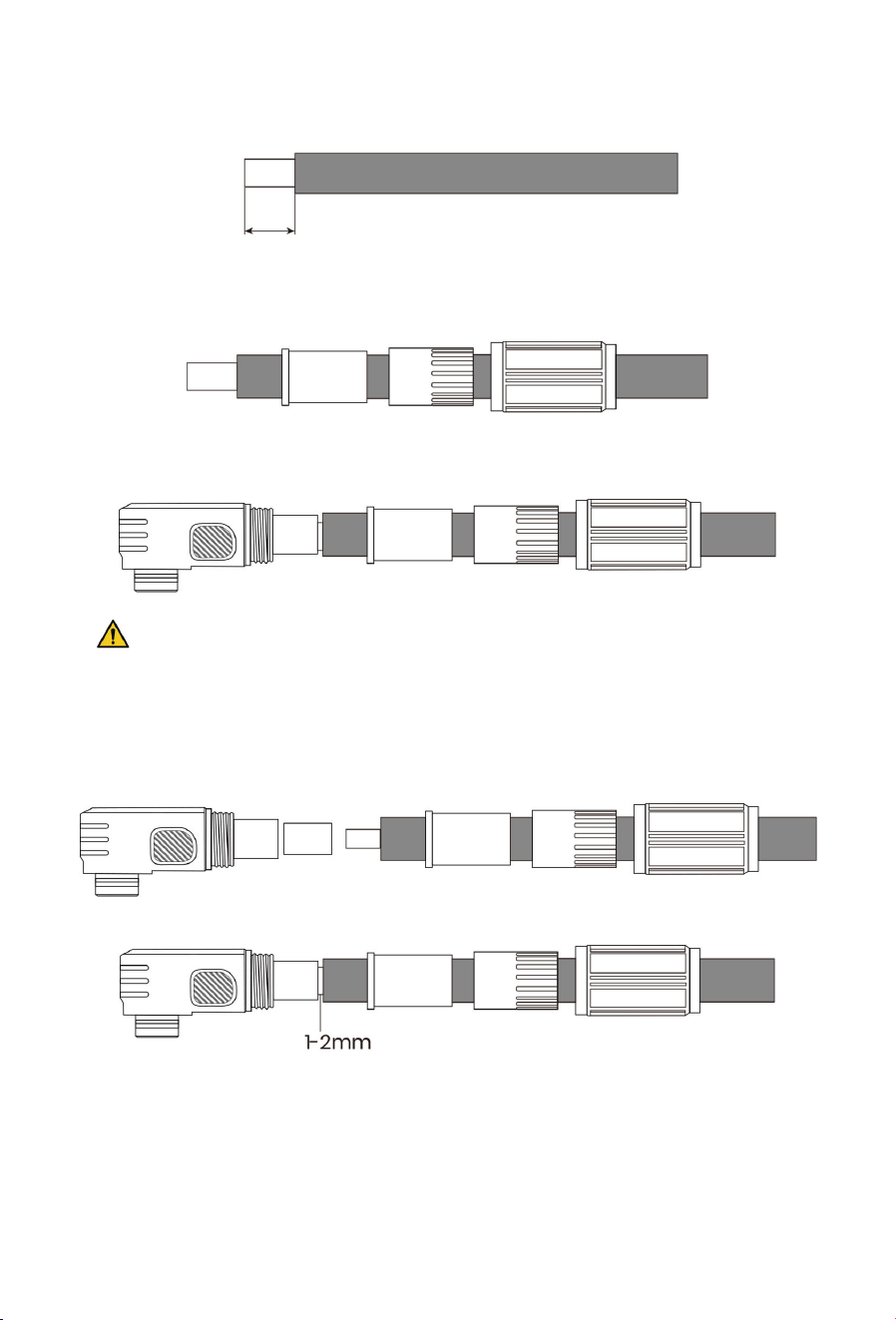
32
Strip the insulation from the end of the cable. Recommended Stripping Length: 20
mm
Step 3
Route the cable through the Cable Gland Nut first, then through the Cable Clamping
Jaw, finally through the Cable Clamping Ring.
Step 4
Insert the stripped cable conductor into the cavity of the Angled Plug.
CAUTION
When the customer provides self-prepared cable harness, the contact area
between the stripped conductor and the Angled Plug cavity may be insufficient.
Slide the Crimping Sleeve over the stripped cable first, then insert it into the Angled
Plug cavity.
Reserve a gap of 1-2 mm during insertion into the Angled Plug cavity
Step 5
Use crimping die and tool with matching specification, and crimp at the specified
terminal position.
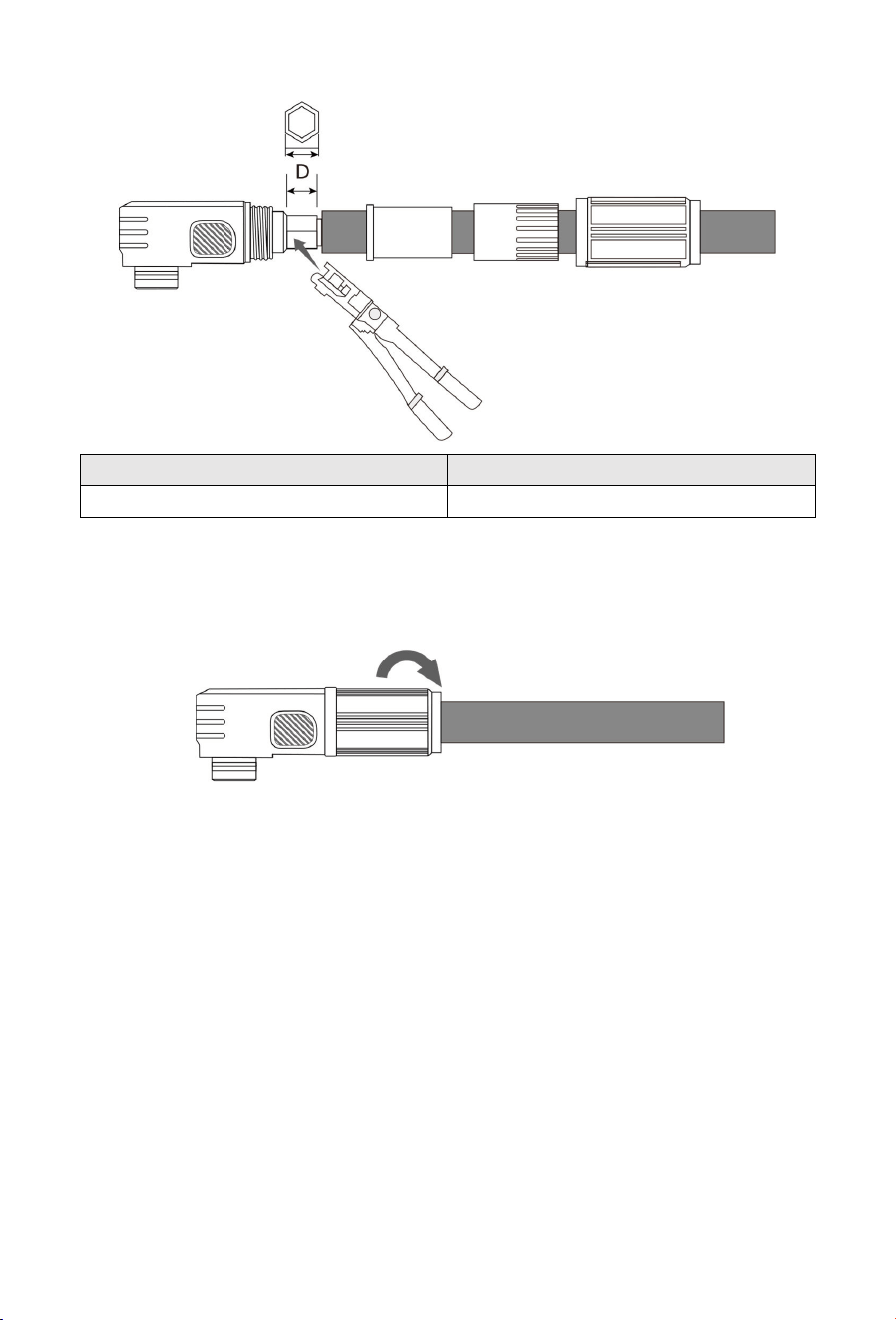
33
Item
Diameter
D
8.55
mm
±0.15
Step 6
Push the Cable Gland Nut forward to butt with the Angled Plug, then tighten the
Cable Gland Nut clockwise. Recommended tightening torque: 0.81 N·m.
Cable modification is completed.
5.2.2 Over-current Protection and Isolation Device
For the Australian Market, an over-current protection and isolation device that isolates
both positive and negative conductors simultaneously is required between the battery
system and Power Conversion Unit. The circuit breaker (over-current protection and
isolation device) selection requirements are as follows:
Type: DC Circuit Breaker
Pole Number: 2P (Recommended)
Rated Voltage: 1000V (Recommended)
Rated Current: 200A (Recommended)
5.3 Cable Connection
Cable connection overview
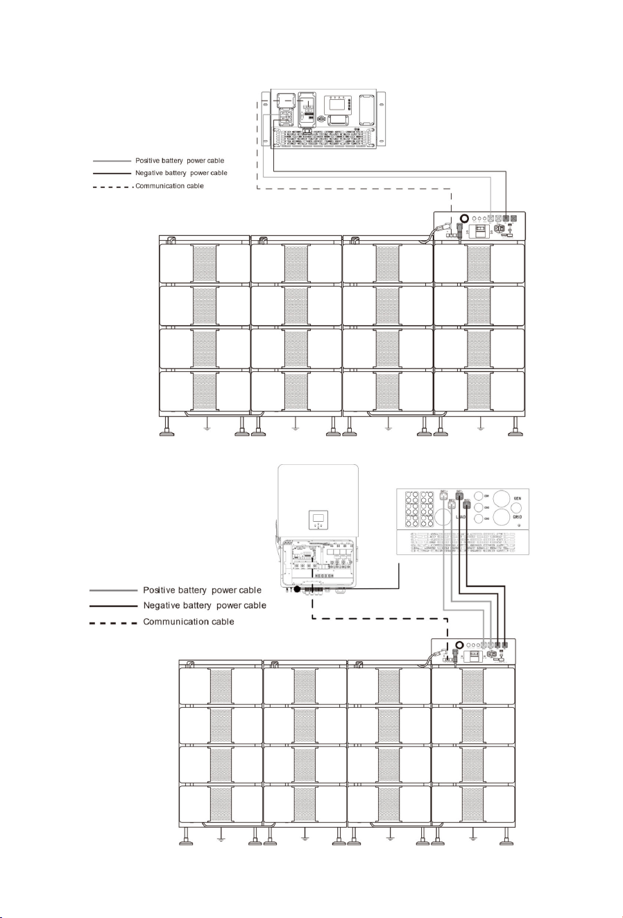
34
Connection between PDU and PCS:
Connection between PDU and inverter:
35
5.3.1 Grounding
EACH BATTERY STACK MUST BE GROUNDED.
Connect one end of the ground cable to the base with a M5*14 Bolt and the other end to
the ground bar at the installation site using a wrench. Recommended torque: 3.2~4.4 N·m.
5.3.2 Power Cable
- For 100/125KW Power Conversion Unit (SUN-100K-PCS01HP3, SUN-125K-PCS01HP3):
Power Cable and Terminal Configuration
Connection Point
Terminal Model
Cable Specification
Quantity
Attach to PCS BAT+
SC50
-
10
42mm
²
1
Attach to PCS BAT
-
SC50
-
10
42mm
²
1
- For 80KW Power Conversion Unit (SUN-80K-SG02HP3-EU-EM6):
Power Cable and Terminal Configuration
Connection Point
Terminal Model
Cable Specification
Quantity
Attach to PCS BAT+
SC25
-
6
26mm
²
2
Attach to PCS BAT
-
SC25
-
6
26mm
²
2
Connect the quick-plug end of the negative and positive Cable (For Connecting PDU to
Power Conversion Unit) to the P+/P- interface of the PDU, and connect the other end to the
positive and negative interfaces of the power conversion unit correspondingly.
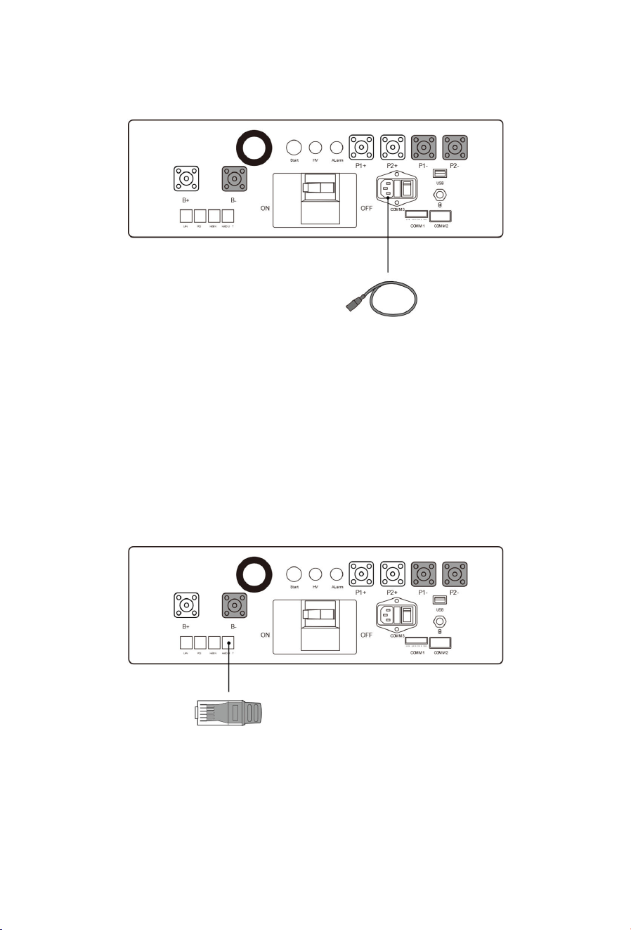
5.3.3 Communication Cable
Insert one end of the communication cable (For Connecting PDU to Power Conversion Unit)
into the PCS terminal of the PDU, and connect the other end to the communication
interface of the power conversion unit.
NOTE
The length of the communication line between the Power Conversion Unit and the PDU
should not exceed 30m.
36
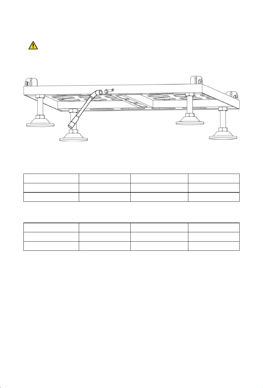
5.3.4 Auxiliary Power Cable
This port must be connected to the power supply of 3A, 50-60Hz, 200~240V when this
equipment is in use, otherwise the fan cannot rotate normally.
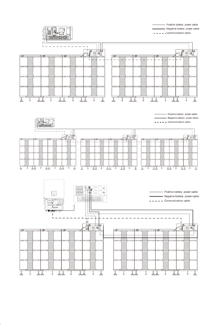
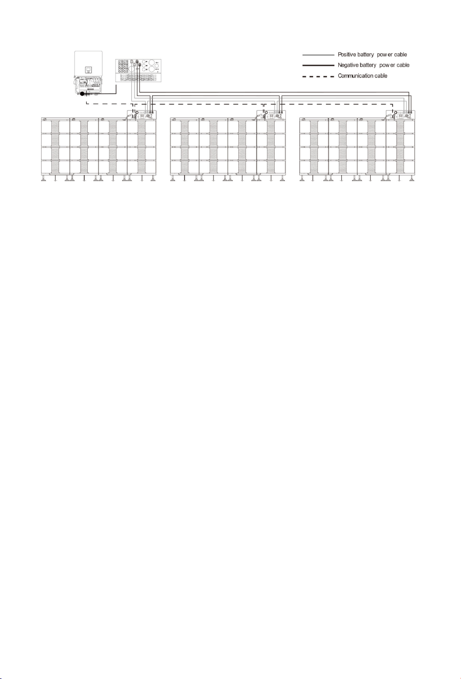
5.4 Multi-System Connection
Power cable:
Connect PDU to PDU using the modified power cables.
Communication cable:
Master PDU: HVBOUT connects to the next slave PDU’ s HVBIN in daisy chain.
Slave PDU: HVBIN connects to the preceding PDU’ s HVBOUT; HVBOUT may connect to the
next PDU or be inserted the Terminal resistor B.
Connection between PDUs and PCS:
37
Or
Connection between PDUs and inverter:
Or
38
5.5 Post-Connection Inspection
After connecting the battery, verify the following items:
Correct polarity of positive and negative cable connections;
Secure and reliable connection of positive and negative terminals;
All bolts are tightened to the specified torque values (refer to the installation torque
table);
Proper cable fastening and intact cable appearance.
39
6 Operation
6.1 Check Before Power-On
All cables are wired correctly and firmly connected, with no looseness or poor
contact.
All fasteners including bolts and screws are fully tightened, with no looseness or loss.
Clear the equipment working area, and strictly prohibit unrelated personnel and
animals from entering the operation range.
Keep foreign objects, especially metal debris, away from the battery area to avoid
short circuit risks.
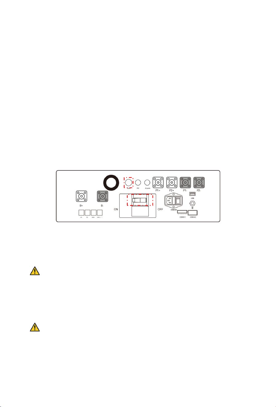
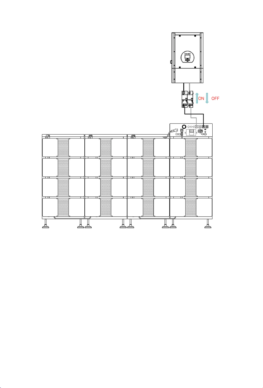
6.2 Power-On
① Turn the circuit breaker handle from “OFF” to “ON” position on the PDU.
② Press the start button on the PDU.
③ Wait for the system to initialize. The start-up sequence is completed when the yellow
HV indicator lights up.
④ Then close the circuit breaker between the Power Conversion Unit and the battery.
⑤ Turn on the Power Conversion Unit.
NOTE: PLEASE REFER TO THE INVERTER MANUAL FOR SPECIFIC OPERATION STEPS.
6.3 Power-Off
① Turn off the inverter.
NOTE: PLEASE REFER TO THE INVERTER MANUAL FOR SPECIFIC OPERATION STEPS.
② Press the start button again.
③ Wait for the yellow HV indicator to go off (about 3 seconds), after which you can turn
the circuit breaker handle from “ON” to “OFF” position.
④ Then open the circuit breaker between the Power Conversion Unit and the battery.
40
41
7 Product Monitoring
NOTE
When the battery system is equipped with a Bluetooth module, the Deye Cloud APP
can be used to monitor the battery status; when the battery is equipped with a Data
Collector Stick or used with a Deye inverter with WiFi function, the Deye Cloud
Website can be used for remote monitoring.
7.1 DEYE Cloud Website
1. Log in to the Deye Cloud with your account and password.
2. After logging in to the Deye Cloud, enter the SN code of the inverter collector in the
search bar (marked by the red box). The detailed information corresponding to the
device will be displayed in the table below. Click the device’s SN code in the table
(marked by the green box) to access the Device Details Page.
3. On the Device Details Page, click Architecture to navigate to the Inverter Architecture
Page.
4. Then, click Battery Module to view the corresponding battery data.
7.2 DEYE Cloud APP
The device can connect to the Deye Cloud App via Bluetooth. After successful login and
registration, you can view information about individual battery packs or the entire system.
Download the Deye Cloud App
Scan the correct code to download the app.
F
or Android
F
or
iOS
For more detailed instructions on using the Deye Cloud App, refer to the operation manual
by scanning the provided QR code. (scan QR code -search “APP” – select and download)

42
8 Maintenance and Storage
8.1 Safety Precautions
DANGER
Maintenance shall be performed or supervised by qualified professional personnel.
Wear personal protective equipment (PPE) and use dedicated insulated tools to
avoid electric shocks or short circuits.
Do not smoke or have open flames in the vicinity of batteries.
Do not wear jewelry, watches or other metallic accessories during servicing.
Disconnect the Li-ion battery from all loads and chargers before cleaning and
maintenance, and fit protective caps over the terminals.
All battery terminals must be disconnected for maintenance.
It is forbidden to dismantle, dissect or open the battery; no serviceable parts are
contained inside the battery.
Electrolyte released from a damaged battery is harmful to skin and eyes and may
be toxic; do not touch it.
WARNING
Never maintain energized batteries. Disconnect mains power and batteries before
moving or reconnecting the equipment, and wait 5 minutes until the equipment
powers off. Verify no hazardous voltage remains with a multimeter before
maintenance.
Improper decommissioning may cause damage to equipment and/or battery
inverters. Ensure the product is decommissioned in accordance with relevant
provisions before maintenance.
CAUTION
Place a warning sign indicating “DO NOT SWITCH ON” at the switch location.
Use an electroscope of the proper voltage level to verify the equipment is
completely de-energized.
Before maintenance or repair, securely connect the loop to be repaired to the main
ground loop; remove the grounding connection upon completion.
Insert and remove cables in accordance with regulations; violent or forced
operations are prohibited.
Clean tools and materials promptly after maintenance, and check for any metallic

43
objects left inside or on top of the product.
When replacing batteries, use spare parts of the same type and specification.
Contact the supplier within 24 hours if any abnormality occurs.
Contact the customer service center for any operation and maintenance queries;
unauthorized operation is prohibited.
8.2 Maintenance Schedule
Maintenance
Item
Frequency Description
Environment
& Safety
6 months
Ensure no flammable or explosive materials around
the product.
Ambient temperature and humidity within operating
ranges.
12 months
Check heat dissipation modules and
vents; clean with
a vacuum cleaner if necessary.
24 months Ensure air inlets and outlets are not blocked.
Appearance
& Structure
1 day
Check that status indicators are in normal condition.
Ensure no foreign objects wrap or cover the product
exterior.
3 months
Visual inspection of the product: no obvious paint
peeling or rust, no dust at vents, no vermin, fasteners
secured, parameter settings normal
12 months
Check screws for no loss or rust
Warning labels and marks legible and
intact; replace
if stained or damaged
24 months
No oxidation or rust
No damage or deformation
Electrical &
Connections
6 months
Cables: securely connected, undamaged, no water
ingress, intact insulation tape at terminals, proper
routing
12 months
Check and retighten electrical connections to
specified torque
Check grounding and equipotential bonding;
grounding resistance ≤ 0.4
Ω
2
4 months
Verify correct wiring
B
attery Pack
3 months
good appearance, proper ambient
44
temperature/humidity, normal operating voltage and
current
6 months
no rust or foreign objects, fan operates properly, BMS
free of alarms
Protection &
Safety
Devices
3 months Verify normal function of equipment switches
System
Operation
1 day
Log in to the management platform (WEB/EMS/APP,
etc.) to check system alarms.
12 months
Check battery module SoC, SoH, voltage, and
temperature via monitoring software.
Perform one system shutdown and restart.
24 months
Check for abnormal noise during equipment
operation.
CAUTION: THE FOLLOWING REPLACEMENT SUGGESTIONS ARE PROVIDED BY OUR
PROFESSIONAL AFTER-SALES PERSONNEL.
Battery replacement is recommended if any of the following is met:
- Battery runtime drops below 70% of the original runtime
- Battery charging time decreases significantly
8.3 Post-Maintenance Requirements
After completing maintenance operations, follows the steps below to retore the site and
archive the maintenance records:
S
tep
O
peration
1. Cleaning & Restoration
Remove all temporary measures (e.g., grounding and
warning signs) and wiring is restored to original condition.
Prevent foreign objects from being left behind or personnel
from inadvertently entering.
2. Power-up & Verification
Restore system power step by step per the power-up
procedure.
Verify that the system has no alarms and operating
parameters are normal.
3. Recording & Archiving
Create traceable maintenance records, including the time,
personnel and equipment status
, and archive the records.

45
8.4 Storage Precautions
DANGER
Keep the product far away from high-temperature heat sources, open flames,
flammable and explosive areas, and all ignition sources.
Do not expose the product to direct sunlight or rain.
During storage, ensure the product is completely disconnected from external
equipment, with all operation indicators off.
Batteries shall be stored in a separate area away from heat sources, stacked in
accordance with the marks on the packing case, and over-limit stacking is strictly
prohibited.
WARNING
Store the product in a dry, clean, well-ventilated indoor area, away from strong
infrared radiation, radiation sources, organic solvents, corrosive gases, and
conductive metal dust.
Handle with care. Dropping, collision, overturning, side placement, or tilting are
strictly prohibited.
Do not stack or roll the product improperly. Follow all outer packaging markings.
The storage ground must be flat and solid.
The storage area must be equipped with qualified fire-fighting facilities, including
fire sand and special fire extinguishers.
Only trained and qualified personnel may operate the product. Wear insulated
gloves and use dedicated insulated tools during operation.
Battery Storage
The optimal storage temperature is 0℃~35℃, and the maximum storage period at
normal room temperature is 6 months. During charge and discharge in lead-acid
mode, the temperature shall be controlled at 5℃~45℃, and the charge/discharge
current shall be kept at 0.2C.
For long-term battery storage, keep the SOC no less than 50%, complete at least one
charge-discharge cycle every 6 months, charge timely and calibrate the SOC to 50%.
Low SOC storage is strictly prohibited to avoid battery damage caused by over-
discharge.
Check the battery voltage monthly if stored for more than 6 months. Storage can be
continued if the voltage is higher than 51.2V; charge immediately in accordance with
46
the specified charging strategy if the voltage is lower than 51.2V.
Long-term storage of lithium batteries will cause capacity attenuation, so overdue
storage shall be avoided as much as possible.
Batteries shall be stored in separate zones, not mixed with other equipment, and ultra-
high stacking is prohibited. If any abnormality such as bulging or smoking occurs during
storage, stop operation immediately, isolate the battery and dispose of it as per
specifications.
Long-term idle storage is strictly prohibited. Regular maintenance and inspection shall
be carried out. Report to the person in charge immediately if the allowable storage
period is exceeded, and do not start use without inspection.
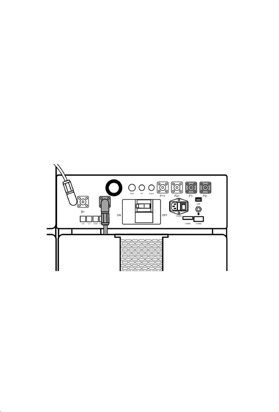
To minimize self-discharge in a long storage period, cut off the connection between the
HVB and batteries by disconnecting one end of the positive HVB power cord as the
picture shows. This will interrupt the use of the 12 V power supply installed in the HVB and
prevent the battery from self-discharging.

47
9 Product Specifications
Model
System
energy (kWh)
Rated DC
power
(kW)
Depth of
Discharge
Composition
BOS-B80
Pro-A3
80.3 40.19 90%
BOS-B-Pack16-AX*5+BOS-
B-PDU-2-A *1
BOS-B96
Pro-A3
96.4 48.23 90%
BOS-B-Pack16-AX*6+BOS-
B-PDU-2-A *1
BOS-B112
Pro-A3
112.5 56.26 90%
BOS-B-Pack16-AX*7+BOS-
B-PDU-2-A *1
BOS-B128
Pro-A3
128.6 64.30 90%
BOS-B-Pack16-AX*8+BOS-
B-PDU-2-A *1
BOS-B144
Pro-A3
144.6 72.34 90%
BOS-B-Pack16-AX*9+BOS-
B-PDU-2-A *1
BOS-B160
Pro-A3
160.7 80.38 90%
BOS-B-Pack16-AX*10+BOS-
B-PDU-2-A *1
BOS-B176
Pro-A3
176.8 88.42 90%
BOS-B-Pack16-AX*11+BOS-
B-PDU-2-A *1
BOS-B192
Pro-A3
192.9 96.46 90%
BOS-B-Pack16-AX*12+BOS-
B-PDU-2-A *1
BOS-B208
Pro-A3
208.9 104.49 90%
BOS-B-Pack16-AX*13+BOS-
B-PDU-2-A *1
BOS-B224
Pro-A3
225.0 112.53 90%
BOS-B-Pack16-AX*14+BOS-
B-PDU-2-A *1
BOS-B240
Pro-A3
241.1 120.57 90%
BOS-B-Pack16-AX*15+BOS-
B-PDU-2-A *1
BOS-B256
Pro-A3
257.2 128.61 90%
BOS-B-Pack16-AX*16+BOS-
B-PDU-2-A *1

48
*BOS-B-Pack16-AX (X=1, 3, 4...)
Cell Chemistry
LiFePO
₄
Battery Module
Energy (kWh)
16.08
Battery Module
Nominal Voltage
(V)
51.2
Battery Module
Capacity (Ah)
314
Battery Module
Number
BOS-B80
Pro
-
A3
BOS-B128 Pro-
A3
BOS-B208
Pro
-
A3
BOS-B256
Pro
-
A3
Battery Module Qty
in Series (Optional)
5 (Min) 8 13 16 (Max)
System Nominal
Voltage (V)
256 409.6 665.6 819.2
System Operating
Voltage (V)
208-292 332.8-467.2 540.8-759.2 665.6-934.4
System Energy
(kWh)
80.38 128.61 209.00 257.23
System Usable
Energy (kWh)
72.27 115.74 188.01 231.48
Max.
DC Power(kW)
46.08
73.73
119.81
147.46
Max.
Charge/Discharge
Current (A)
*1
180
Working
Temperature (
℃
)
Charge:0 ~ 55 Discharge:-20 ~ 55
Status Indicator Yellow:Battery High Voltage Power On
Red
:
Battery System Alarm
Communication
Port
TCP / RS485 / CAN
Humidity
5% ~ 85%
Altitude
≤ 3000m
IP Rating of
Enclosure
IP20

49
Dimension (W×D×H,
mm)
2150 × 1136 × 800
Installation
Rack Mounted
Storage
Temperature (
℃
)
0 ~ 35
Recommend Depth
of Discharge
90%
Cycle Life
25±2°C, 0.5C / 0.5C, EOL70%≥6000
Certification
CE / IEC62619 / IEC62040 / UN38.3
1.The current is affected by temperature and SOC.
2.Made in China.

50
Appendix I Troubleshooting
Screen displays the logic
1. After startup, the screen is on for 20 seconds and then off. Each time the touch screen is
lit behind the scenes for 20 seconds, and then turned off until the next touch.
2. The first 2s of boot, the screen shows all.
3. The fault code starts from F001 in ascending order.
4. Each fault is displayed for 5s, and then switch to the next fault.
5. If all faults are rectified, keep the previous fault on the screen for 5 seconds and clear
the screen.
F001 ALARM_ID_SUM_OVER_VOLT_LEV_2 Overvoltage
F002
ALARM_ID_SUM_LOW_VOLT_LEV_2
The total voltage is too
low
F003
ALARM_ID_CHG_OVER_TEMP_LEV_2
Charging temperature is
too high
F004
ALARM_ID_DSG_OVER_TEMP_LEV_2
High discharge
temperature
F005
ALARM_ID_CHG_LOW_TEMP_LEV_2
The charging
temperature is too low
F006
ALARM_ID_DSG_LOW_TEMP_LEV_2
The discharge
temperature is too low
F007
ALARM_ID_OVER_DIFF_VOLT_LEV_2
Excessive voltage
difference
F008
ALARM_ID_OVER_DIFF_TEMP_LEV_2
Excessive temperature
differentials
F009
ALARM_ID_CELL_OVER_VOLT_LEV_2 Cell overvoltage
F010 ALARM_ID_CELL_LOW_VOLT_LEV_2 Cell undervoltage
F011 ALARM_ID_PRE_CHG_RES_OVER_TEMP_LEV_2
The temperature of the
precharge resistance is
too high
F012 ALARM_ID_NORTH_CONNECTOR_OVER_TEMP_LEV_2
The temperature of the
BMS connector is too
high
F013 ALARM_ID_SOUTH_CONNECTOR_OVER_TEMP_LEV_2
The BMU connector
temperature is too high.
F014 ALARM_ID_CHG_OVER_CUR_LEV_2 Charging current fault

51
F015 ALARM_ID_DSG_OVER_CUR_LEV_2 Discharge current fault
F016 ALARM_ID_SOC_OVER_LEV_2 High SOC fault
F017 ALARM_ID_INSULATION_FAILURE_TWO Insulation fault
F018 ALARM_ID_HEAT_OVER_TEMP_LEV_2
The heating film is too
high
F019 ALARM_ID_SOC_LOW_LEV_2 The SOC is too low
F020
ALARM_ID_DSG_RELAY_ADHESION
Discharge relay
adhesion
F021 ALARM_ID_POS_RELAY_ADHESION
Total positive relay
bonding
F022
ALARM_ID_CHG_RELAY_ADHESION
The charging relay is
glued
F023
ALARM_ID_HEAT_RELAY_ADHESION The heating relay is glued
F024
ALARM_ID_ULTIMATE_PROTECTION Ultimate protection
F025
ALARM_ID_POWER_SUPPLY_FAULT Abnormal supply voltage
F026
ALARM_ID_FUSE_BLOWN Blown fuse
F027
ALARM_ID_BMU_ADDR_REPEAT The BMU repeatedly fails
F028
ALARM_ID_BMS_ADDR_REPEAT
The BMS is faulty
repeatedly
F029
ALARM_ID_INTERNAL_COMM_ERROR
The internal CAN
communication fails
F030
ALARM_ID_PCS_CAN_COMM_FAIL
The PCS CAN
communication fails
F031 MBMS_SAM_SIG_ID_PCS_ERROR_STATE
The PCS RS485
communication fails
F032
ALARM_ID_PCS_RS485_COMM_ERROR
The PCS RS485
communication is
abnormal
F033
ALARM_ID_FUSE_VOLT_SAMP_ERROR
The FUSE total voltage
collection is abnormal
F034
ALARM_ID_BAT_VOLT_SAMP_ERROR
The internal total voltage
collection is abnormal
F035
ALARM_ID_MOT_VOLT_SAMP_ERROR
The Mot total voltage
collection is abnormal

52
F036
ALARM_ID_HTP_VOLT_SAMP_ERROR
The total heating voltage
collection is abnormal
F037
ALARM_ID_CELL_VOLT_SAMPLE_ERROR Voltage collection fault
F038
ALARM_ID_TEMP_SAMPLE_ERROR
Temperature acquisition
fault
F039
ALARM_ID_CURRENT_SAMPLE_ERROR Current acquisition fault
F040
ALARM_ID_CURRENT_MODULE_FAULT Current module fault
F041 ALARM_ID_POS_RELAY_DRIVE_FAULT
Total positive relay drive
failure
F042
ALARM_ID_CHG_RELAY_DRIVE_FAULT
Charging relay drive
failure
F043
ALARM_ID_DSG_RELAY_DRIVE_FAULT
Discharge relay drive
failure
F044
ALARM_ID_HEAT_RELAY_DRIVE_FAULT
Heating relay drive
failure
F045
ALARM_ID_EEPROM_ERROR
The EEPROM storage is
faulty
F046
ALARM_ID_PRECHAGE_ERROR The precharge failed
F047
ALARM_ID_CHG_VOLT_LOW
The charging voltage is
too low
F048
ALARM_ID_BMU_COMM_ERROR
The BMU communication
is faulty
F049
ALARM_ID_BMU_NUMBER_ERROR
The number of BMUs is
abnormal
F050
ALARM_ID_MBMS_NTC_BREAKLINE_ERROR
Temperature collection
of the BMS connector is
abnormal
F051 ALARM_ID_BMU_NTC_BREAKLINE_ERROR
The temperature
collection of the BMU
connector is abnormal
F052
ALARM_ID_PACK_THERMAL_RUNAWAY
PACK thermal runaway
fault
F053
ALARM_ID_PACK_FIRE_FAULT PACK fire failure
F054
ALARM_ID_TCP_CONNECT_FAIL TCP connection failure
F055
ALARM_ID_W5500_SPI_COMM_FAIL
The W5500SPI
communication fails

53
F056
ALARM_ID_LC_COMM_LOST LC communication loss
F057
ALARM_ID_PACK_AFE_COMM_ERROR,
BMU AFE communication
fails
F058
ALARM_ID_BLE_INIT_FAULT
Description Bluetooth
initialization failed
F059
ALARM_ID_CELL_TYPE_MISMATCH_ERROR
The battery type does
not match
F060
ALARM_ID_SINGLE_CLUSTER_POWER_DOWN
Single cluster
emergency power
-
off
Different types of faults are below:
System
faults
Fault types Trigger conditions
Charge over-current alarm /
Charge over-
current
protection
Charging current exceeds 176A for 2
minutes; or exceeds 210A for 5 seconds; or
exceeds 235A for 0.5 seconds.
Discharge over-current alarm /
Discharge over-
current
protection
Discharge current exceeds 176A for 2
minutes; or exceeds 210A for 5 seconds; or
exceeds 235A for 0.5 seconds.
Charge overtemperature
alarm
Exceeding the parameter set value and
set time (Maximum cell
temperature >50°C, 5s)
Charge overtemperature
protection
Exceeding the parameter set value and
set time (Maximum cell
temperature >55°C, 2s)
Discharge overtemperature
alarm
Exceeding the parameter set value and
set time (Maximum cell
temperature >50°C, 5s)
Discharge overtemperature
protection
Exceeding the parameter set value and
set time (Maximum cell
temperature >55°C, 2s)
Charge under temperature
alarm
Exceeding the parameter set value and
set time (Minimum cell temperature <5°C,
5s)

54
Charge under temperature
protection
Exceeding the parameter set value and
set time (Minimum cell temperature <0°C,
2s)
Discharge under temperature
alarm
Exceeding the parameter set value and
set time (Minimum cell temperature <-
10°C, 5s)
Discharge under temperature
protection
Exceeding the parameter set value and
set time (Minimum cell temperature <-
20°C, 2s)
Excessive differential voltage
alarm
Exceeding the parameter set value and
set time (Voltage difference >500mV, 2s)
Excessive differential voltage
protection
Exceeding the parameter set value and
set
time (Voltage difference >800mV, 2s)
Excessive differential
temperature alarm
Exceeding the parameter set value and
set time (Temperature difference
between highest and lowest >10°C, 2s)
Excessive differential
temperature protection
Exceeding the parameter set value and
set time (Temperature difference
between highest and lowest >15°C, 2s)
SOC too high /
Cell overvoltage alarm
Exceeding the
parameter set
value and set time
(Maximum cell
voltage >3.62V, 1s)
To maintain
consistency, cut
off the charging
immediately when
the full charge
calibration rated
voltage of 3.6V is
reached. When the
voltage drops to
3.35V, restart it with
the turned-
off red
light indicator. All
protective red light
indicators are
always on!
Cell overvoltage protection
Exceeding the
parameter set
value and set time
(Maximum cell
voltage >3.65V, 1s)
Cell undervoltage alarm
Exceeding the
parameter set
value and set time
(Minimum cell
voltage <2.7V, 2s)
Cell undervoltage protection
Exceeding the
parameter set
value and set time
(Minimum cell
voltage <2.5V, 2s)

55
Pre-
charge resistor
overtemperature alarm
Exceeding the parameter set value and
set time (Precharge resistor
temperature >55°C, 2s)
Pre-
charge resistor
overtemperature protection
Exceeding the parameter set value and
set time (Precharge resistor
temperature >85°C, 2s)
Insulation level 1
Exceeding the parameter set value and
set time (Insulation resistance <500MΩ, 3
times)
Insulation level 2
Exceeding the parameter set value and
set time (Insulation resistance <100MΩ, 3
times)
Heating film overtemperature
alarm
/
Heating film overtemperature
protection
/
BMS connector
overtemperature alarm
Exceeding the parameter set value and
set time (Maximum temperature of BMS
connector >75°C, 2s)
BMS connector
overtemperature protection
Exceeding the parameter set value and
set time (Maximum temperature of BMS
connector >85°C, 2s)
BMU connector
overtemperature alarm
Exceeding the parameter set value and
set time (Maximum temperature of BMU
connector >75°C, 2s)
BMU connector
overtemperature protection
Exceeding the parameter set value and
set time (Maximum temperature of BMU
connector >85°C, 2s)
Power loop overtemperature
alarm
/
Power loop overtemperature
protection
/
SOC too low
Exceeding the parameter set value and
set time (SOC is 0%)
Total voltage too high alarm
Exceeding the parameter set value and
set time (Total voltage >57.6V*N (N=current
system PACK count), 1s)
Total voltage too high
protection
Exceeding the parameter set value and
set time (Total voltage >58.4V*N

56
(N=current system PACK count), 1s)
Total voltage too low alarm
Exceeding the parameter set value and
set time (Total voltage <44.8V*N
(N=current syst
em PACK count), 2s)
Total voltage too low
protection
Exceeding the parameter set value and
set time (Total voltage <41.6V*N (N=current
system PACK count), 2s)
Discharge relay adhesion
Discharge relay control command open,
but actual feedback indicates discharge
relay closed, 3s
Charge relay adhesion
Charge relay control command open, but
actual feedback indicates charge relay
closed, 3s
Heating relay adhesion
Heating circuit voltage high detected
after heating relay disconnection, 3s
Limit protection
Exceeding the parameter set value and
set time (Condition 1: Maximum cell
voltage ≥3.8V)
Condition 2: (Minimum cell voltage ≤1.5V
and no voltage acquisition fault) or
(Maximum cell temperature ≥65°C) or
(Minimum cell temperature ≤-30°C and no
temperature sensor disconnection fault)
or (Connector temperature ≥90°C) lasting
2s
Extreme protection triggered if either
Condition 1 or Condition 2 is met
Abnormal power supply
voltage
Exceeding the parameter set value and
set time (Supply voltage >14V or supply
voltage <10V, 5s)
Master positive relay adhesion
Main positive relay has no close
command, but actual feedback indicates
main positive relay closed, 3s
Fuse Blown
No high voltage detected after loop relay
closure, 5s
Repeated BMU address fault BMU with the same number
Repeated BMS address fault BMS with the same number

57
INTER-
CAN BUS
communication failure
Loss of communication between BMS
PCS-
CAN BUS communication
failure
The heartbeat message of the Power
Conversion Unit
is not received for a long
time
RS485 communication failure /
RS485 communication
abnormal
/
External(FUSE)
total voltage
acquisition fault
/
Internal total voltage
acquisition fault
The difference between the acquired
internal total
voltage and the
accumulated internal total voltage
exceeding the set value
(
10V
,
5s
)
SCHG total voltage acquisition
fault
/
Cell voltage acquisition fault Battery voltage sampling disconnection
Temperature acquisition
failure
BMS NTC sampling disconnection or BMU
NTC sampling disconnection or battery
temperature sampling disconnection
Current acquisition fault
Exceeding the parameter set value and
set time (Acquired charging current >500A
or discharging current >500A, 3s)
Current module fault
Current module reverse connection
(charging current and voltage drop, or
discharging current and voltage rise, 60s)
or current module not configured (shunt
sampling type configured incorrectly)
Main positive relay drive failure
fault
Control main positive relay close, but
actual feedback indicates open, 5s
Charging relay drive failure
fault
Control charging relay close, but actual
feedback indicates open, 5s
Discharging relay drive failure
fault
Control discharging relay close, but actual
feedback indicates open, 5s
Heating relay drive failure fault
Heating circuit low voltage detected after
heating relay connection, 5s

58
EEPROM storage failure EEPROM write failure during self-test
RTC clock fault
The external RTC failed to enabl
e the
charging function
Pre-charge failure Pre-charge timeout,4s
Charging voltage too low
The minimum cell voltage is lower than the
set value
BMU lost
BMU message not received for a long
time
,
10s
Abnormal number of BMU
The difference between the acquired
internal total voltage and the
accumulated internal total voltage
exceeding the set value(27.2V,5s)
Mot total pressure acquisition
abnormal
DC circuit is closed, but MOT total voltage
<10V, 5s
BMS connector temperature
acquisition abnormal
BMS connector north positive terminal
temperature, BMS connector south
positive terminal temperature, BMS
connector south negative terminal
temperature, BMS connector north
negative terminal temperature,
precharge resistor
temperature reads 0
for 20s (BMS NTC acquisition
disconnected)
BMU connector temperature
acquisition abnormal
BMU connector minimum temperature
reads 0 for 20s (BMU NTC acquisition
disconnected)
PACK fan fault Fan detected not rotating during startup
PACK thermal runaway fault
Condition 1: Maximum cell temperature
exceeds 65°C
Condition 2: Voltage drop rate exceeding
25%/s or temperature rise rate exceeding
1°C/s occurs continuously more than 30
times
Both Condition 1 and Condition 2 must be
met for thermal runaway to occur
PACK fire protection fault Battery pack detects aerosol discharge

59
TCP connection failure /
W5500 SPI communication
failure
/
LC communication loss /
BMU software version
discrepancy fault
BMU software version mismatch
BMU AFE communication
failure
BMU and AFE acquisition chip
communication failure
BMU cell type mismatch fault
Battery type filled in battery pack does not
match battery type filled in high-voltage
box during system power
-
on self
-
test
Single cluster emergency
power
-
off fault
Emergency power-off signal read from DI
is at low level, 2s
Bluetooth initialization failure
fault
Bluetooth initialization failed 10 times
Environmental controller
communication loss
/
Air conditioning
communication loss
/
Air conditioning alarm /
Lightning protection /
Exhaust valve alarm /
Lead-acid battery fault /
Cabin-level combustible gas
fault
/
Battery compartment door
open fault
/
Aerosol feedback fault /
Environmental control board
smoke sensor fault
/

60
Environmental control board
temperature sensor fault
/
Environmental control board
emergency stop fault
/
Environmental control board
water immersion fault
/

61
Appendix II Emergency Handling
DANGER
In the event of natural disasters (earthquake, typhoon, flood, wildfire, etc.): Prioritize
personnel safety, cut off power and stop the ESS immediately.
Do NOT operate damaged equipment without professional inspection and qualified
testing after the disaster.
Keep away from waterlogged or fire-damaged units and contact our service
engineers for professional handling.
WARNING
When the air intake/exhaust system is operating, do NOT face the exhaust vents
under any circumstance.
Refer to the user manual/product manual for product information. Do NOT ACCESS
the product if safety cannot be guaranteed.
Fire/Explosion Hazards
Evacuate immediately to at least 50 meters away from the site and call the fire
department.
Wear respiratory protection. Disconnect the upstream power supply only when safe.
Isolate the accident area only when safe to keep unauthorized personnel away.
Post-incident maintenance must be performed by professionals or our after-sales
engineers.
Electric Shock
Ensure personal safety, then disconnect the power supply immediately to avoid
secondary electric shock.
Use an insulated object to separate the victim from the power source and perform
first aid such as cardiopulmonary resuscitation (CPR).
Call the emergency medical number immediately to obtain professional medical
treatment.
Protect the accident scene for investigation and evidence preservation.
Contact professionals to conduct a comprehensive inspection of the ESS. The
system may only be put back into use after repair or replacement and passing
qualified testing.

62
Chemical Hazards
In case of electrolyte leakage, evacuate personnel from the affected area and notify
the relevant personnel immediately. Professionals shall conduct safe collection and
proper disposal of leaked substances.
Toxic gases may be released during battery combustion or damage; evacuate
personnel to a safe area immediately. If personnel are exposed or injured, call the
emergency medical number for professional treatment. Respiratory protection,
protective clothing and other safety equipment must be worn during hazard
handling.
Mechanical Injury
In the event of equipment tipping, battery pack dropping or component
detachment, disconnect power and stop ESS operation immediately.
In case of personnel injury, administer first aid (hemostasis, bandaging, etc.) and call
the emergency medical number immediately.
If obvious odor, damage, smoke or fire is detected, evacuate personnel immediately,
call the fire department, and allow professionals to handle firefighting and
subsequent treatment.
If any abnormalities are observed, professionals shall use move the battery pack to
an open, safe area, let it stand for 1 hour while monitoring temperature, and contact
the engineers.
Contact professionals to repair or replace damaged components. The system may
only be returned to service after passing inspection and testing.
Natural Disasters
In the event of natural disasters including earthquake, typhoon, flood, wildfire, etc.,
disconnect the power supply and stop ESS operation immediately.
If the ESS is submerged or flooded, do not touch the equipment and keep clear of
the waterlogged area.
Do not use water-soaked batteries under any circumstances. Contact a qualified
battery recycling service for proper disposal and scrapping.
Before a wildfire approaches, establish a firebreak around the ESS and prepare
adequate fire-fighting equipment such as fire extinguishers, fire sand, fire hoses, etc.
After the disaster, contact professionals to fully inspect the support structure, electrical
connections, etc. The system may only be reused after repair/replacement and qualified
testing.