Installation
Operation
Maintenance
Owner’s Manual
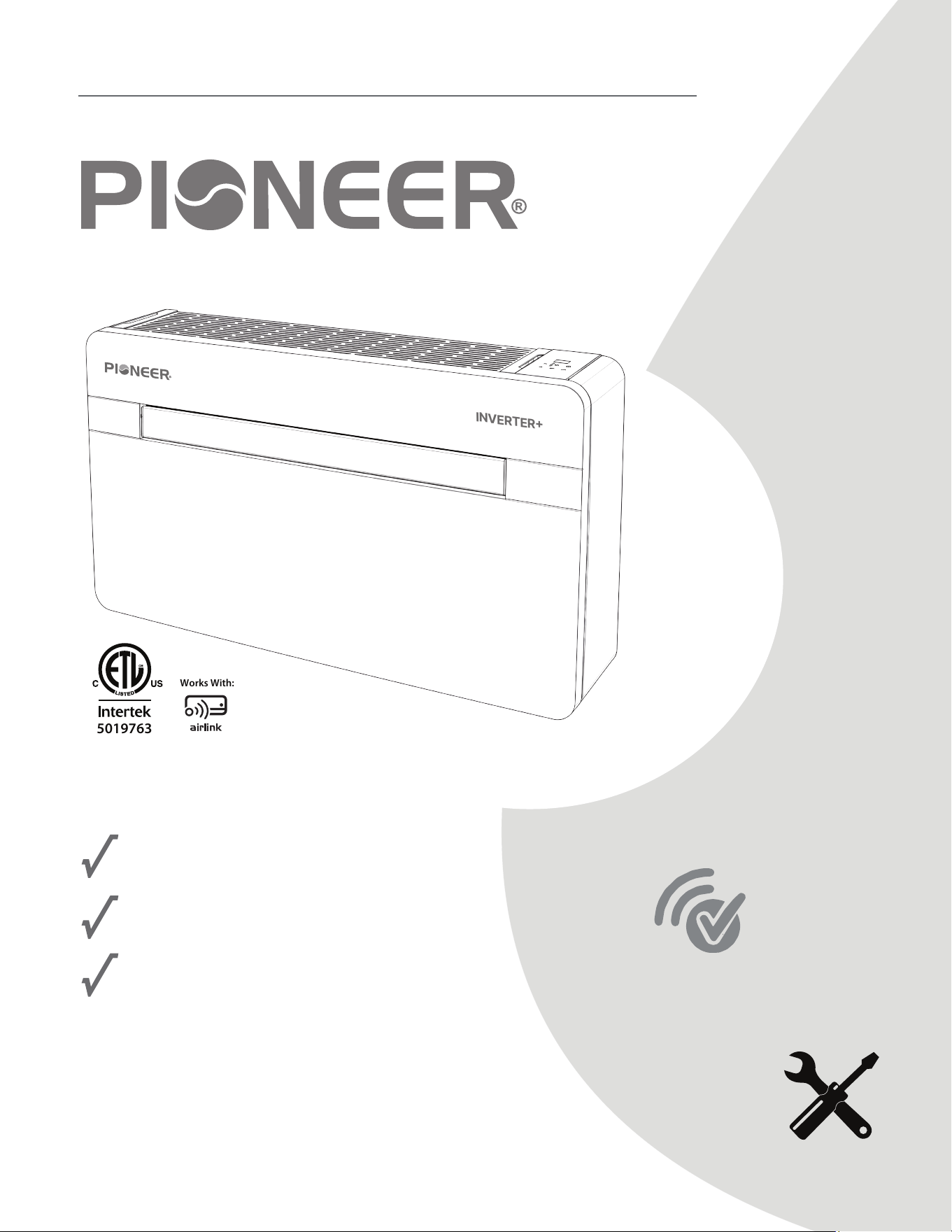
ALL-IN-ONE PACKAGED CONSOLE INVERTER HEAT PUMP
SELF-CONTAINED MONOBLOCK SYSTEM - NO OUTDOOR UNIT REQUIRED
MODEL NO: PYM012GZUI16RD
IMPORTANT NOTICE:
Please read this manual carefully before installing
or operating your new air conditioning system.
Be sure to save this manual for future reference.
Wi-Fi App
Control
Ready
FCC IDENTIFIER: 2ANDL-CB3S
5019763
Works With:
REV26429
INVERTER+

Table of Contents
I. General Information
II. Installation
III. Use and Maintenance
1. Important Safety Instructions......................................................................................................................................................................1
2. Introduction..............................................................................................................................................................................................................6
3. Receiving the Merchandise..................................................................................................................
........................................................7
4. Handling......................................................................................................................................................................................................................7
5. List of Accessories...............................................................................................................................................................................................7
6. Technical Aspects...............................................................................................................................................................................................8
7. Wiring Diagram......................................................................................................................................................................................................9
1. Air Conditioner Placement..........................................................................................................................................................................10
2. Drilling Template..................................................................................................................................................................................................11
3. Drilling the Wall...............................................................................................................................................
.......................................................12
4. Condensate Drain..............................................................................................................................................................................................12
5. Exterior Grilles Installation............................................................................................................................................................................13
6. Air Duct Pipes Installation..............................................................................................................................................................................14
7. Drainage Pipe Connection...........................................................................................................................................................................14
8. Cold Climate Drainage Configuration................................................................................................................................................15
9. Unit Wall Bracket Mounting.........................................................................................................................................................................15
10. Configuring External 24V Wall Thermostat....................................................................................................................................16
1. Introduction to Remote Icons.....................................................................................................................................................................18
2. Remote Control Functions............................................................................................................................................................................18
3. Heating Mode.................................................................................................................................................
.......................................................19
4. Cooling Mode........................................................................................................................................................................................................19
5. Dry Mode................................................................................................................................................................................................................20
6. Fan Mode................................................................................................................................................................................................................20
7. Sleep Mode............................................................................................................................................................................................................21
8. Auto Mode...............................................................................................................................................................................................................21
9. Timer Off Function...........................................................................................................................................................................................22
10. Timer On Function............................................................................................................................................................................................22
11. Electrical Heat Function................................................................................................................................................................................23
12. Onboard Control Function.........................................................................................................................................................................24
13. Wi-Fi Connection and Instructions for Usage...............................................................................................................................25
14. Remote Control Battery Installation....................................................................................................................................................25
15. Fresh Air System................................................................................................................................................................................................25
16. Maintenance...............................................................................................................................................
........................................................25
17. Troubleshooting................................................................................................................................................................26
18. Error Codes...........................................................................................................................................................................................................27
1
DANGER
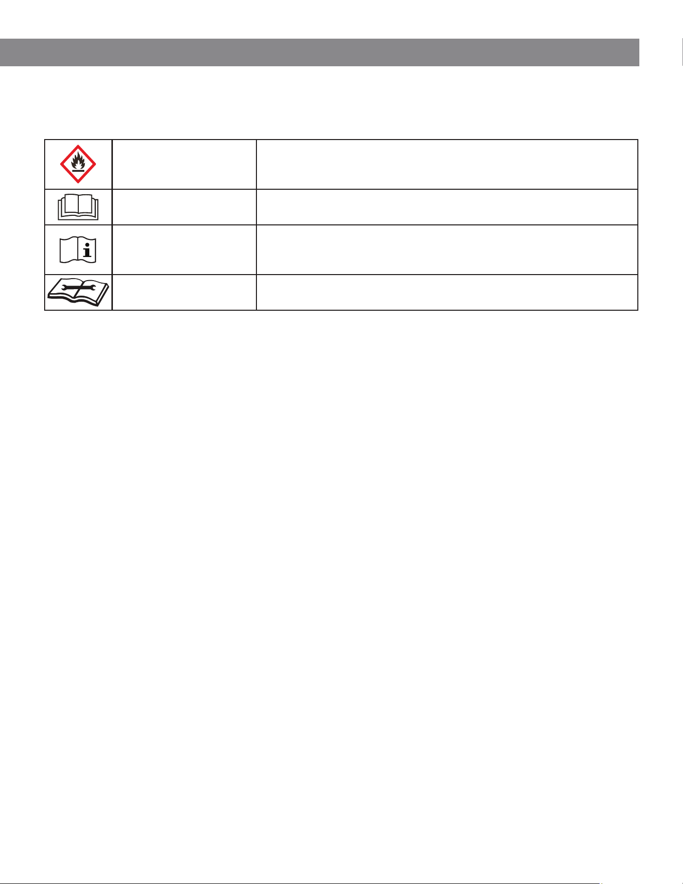
1. Important Safety Information
The following symbols are used throughout this manual to indicate important safety information.
Read and understand all safety instructions before installing, operating, or servicing the unit.
Safety Precautions
Flammable Refrigerant
This symbol indicates that the appliance uses a flammable
refrigerant. If refrigerant leaks and is exposed to an external
ignition source, there is a risk of fire.
WARNING
Read the Manual
This symbol indicates that the operation manual must be read
carefully before installing, operating, or servicing the equipment.
CAUTION
Service Personnel Only
This symbol indicates that installation, servicing, or repair must
be performed by qualified service personnel and should be
carried out in accordance with the installation manual.
NOTICE
Additional Informa
tion
This symbol indicates that additional information is available in
the operation or installation manual.
I. GENERAL INFORMATION
Read all instructions before installing or operating this unit.
This appliance is not intended for use by persons
(including children) with reduced physical, sensory, or
mental capabilities, or by individuals lacking experience
or knowledge, unless they are supervised or have been
instructed on safe operation by a person responsible for
their safety.
Children must be supervised to ensure that they do not
play with the appliance. Smoking, open flames, and other
ignition sources are strictly prohibited near the unit.
Installation and Service Requirements
• Installation and service must be performed only by
qualified personnel.
• Technicians working on the refrigerant circuit must
hold a current certification issued by an accredited
authority verifying their competence in handling
refrigerants safely.
• Servicing must only be performed as recommended
by the manufacturer.
• Maintenance or repair requiring assistance from
additional personnel must be carried out under the
supervision of a technician qualified to work with
flammable refrigerants.
• Ensure that air inlet and outlet openings remain
unobstructed at all times.
Servicing Precautions
Area Safety Checks
Before beginning work on equipment containing
flammable refrigerants, safety checks must be
performed to minimize the risk of ignition.
Prior to servicing the refrigeration system, ensure that the
work area is free of ignition sources and that adequate
ventilation is present.
Work Procedures
Service work must be carried out using controlled
procedures designed to minimize the presence of
flammable gas or vapor while work is being performed.
This product is a self-contained packaged heat pump
system designed for indoor installation.
No outdoor condensing unit is required.
WARNING
• Do not use methods to accelerate the defrosting
process or to clean the unit other than those
recommended by the manufacturer.
• Do not pierce, burn, or mechanically damage the
refrigeration circuit.
• Refrigerant may be odorless, and leaks may not be
easily detectable.
• The unit must be installed and operated in accordance
with all national and local codes and regulations.
The appliance must be stored in a well-ventilated area
where the room size complies with the minimum
installation requirements specified for the equipment.
The unit must not be stored in areas containing
continuously operating ignition sources such as:
• Open flames
• Gas appliances
• Electric heaters
The appliance must be stored in a manner that prevents
mechanical damage.

2
I. GENERAL INFORMATION
Work Area Safety
All personnel performing maintenance or service work
must be informed of the nature of the work being
performed.
Avoid working in confined spaces whenever possible.
The area surrounding the workspace should be secured
and controlled. Ensure the working environment is safe
and that any flammable materials are removed or
properly managed before work begins.
Ventilation Requirements
Ensure the work area is located outdoors or is adequately
ventilated before opening the refrigeration circuit or
performing hot work.
Ventilation must be maintained throughout the entire
service operation.
The ventilation system should safely disperse any
released refrigerant and preferably allow for released
refrigerant to discharge outdoors.
Inspection of Refrigeration Equipment
When electrical components are replaced, they must be
approved for the intended application and meet the
correct specifications.
The manufacturer's service and maintenance instructions
must always be followed.
If there is any uncertainty regarding equipment suitability
or service procedures, consult the manufacturer’s
technical support department.
For systems using flammable refrigerants, the following
checks must be performed:
• The refrigerant charge size must comply with the
room size where the equipment is installed.
• Ventilation equipment and air outlets must be
functioning properly and not obstructed.
• If an indirect refrigeration circuit is used, the
secondary circuit must be inspected for refrigerant
presence.
• Equipment markings and safety labels must remain
clearly visible and legible. Any damaged or
unreadable labels must be replaced.
• Refrigerant piping and components must be installed
in locations where they are not exposed to
substances that may cause corrosion, unless the
components are made from corrosion-resistant
materials or are adequately protected.
Checking for Presence of Refrigerant
Before and during service work, the area must be
monitored using an appropriate refrigerant leak
detector to ensure technicians are aware of potentially
flammable atmospheres.
Leak detection equipment used in areas containing
flammable refrigerants must be:
• Suitable for use with A2L refrigerants
• Non-sparking
• Properly sealed or intrinsically safe
Fire Extinguishing Equipment
If hot work is being performed on the refrigeration system
or associated components, appropriate fire
extinguishing equipment must be readily available.
A dry chemical or CO₂ fire extinguisher must be located
near the work area, particularly near charging or service
locations.
Elimination of Ignition Sources
Personnel performing work on refrigeration systems that
involve exposure of piping or components containing
flammable refrigerant must not introduce any ignition
sources that could create a fire or explosion hazard.
Possible ignition sources include, but are not limited to:
• Open flames
• Sparks
• Smoking materials
Smoking is strictly prohibited in areas where refrigerant
service, installation, repair, or disposal is being performed.
Before beginning work, inspect the surrounding area to
ensure that no flammable hazards or ignition sources
are present.
3
I. GENERAL INFORMATION
Electrical Component Safety Checks
Maintenance and repair of electrical components must
include initial safety inspections and component testing.
If a fault is identified that could compromise safety, do
not connect electrical power to the system until the issue
has been corrected.
If immediate repair is not possible but continued
operation is necessary, an appropriate temporary
solution must be implemented and the equipment
owner must be notified.
Initial safety checks must confirm:
• Capacitors are fully discharged before service work
begins, performed in a manner that prevents
sparking.
• No live electrical components or wiring are exposed
during charging, recovery, or purging of refrigerant.
• The equipment grounding (earth bonding) is
continuous and intact.
Repairs to Sealed Components
When servicing sealed electrical components, all
electrical power supplies must be disconnected from
the equipment before any sealed covers or enclosures
are removed.
If it is absolutely necessary for the equipment to remain
energized during servicing, a continuously operating
refrigerant leak detection device must be installed at
the most critical location to provide warning of any
potentially hazardous condition.
Particular attention must be given when working on
electrical components to ensure that the equipment
enclosure is not modified or damaged in a manner that
reduces its protective rating.
This includes avoiding:
• Damage to cables or wiring
• Excessive numbers of electrical connections
• Terminals that do not meet original specifications
• Damage to seals or gaskets
• Incorrect installation of cable glands
Ensure that the equipment is securely mounted and
properly supported. Verify that all seals and sealing
materials remain in good condition and have not
deteriorated to the point where they can no longer
prevent the ingress of flammable refrigerant vapors or
atmospheres.
Repairs to Sealed Components (Cont’d)
Replacement components must be approved by the
manufacturer and installed in accordance with the
manufacturer’s specifications.
IMPORTANT: The use of silicone sealants may reduce the
effectiveness of certain types of refrigerant leak
detection equipment.
Components classified as intrinsically safe do not need
to be electrically isolated prior to servicing.
Repairs to Spark-Protected Components
Do not apply permanent inductive or capacitive loads to
the circuit unless it has been verified that doing so will not
exceed the permissible voltage and current limits of the
equipment.
Intrinsically safe components are the only components
that may be serviced while energized in the presence of
a potentially flammable atmosphere.
Test equipment used during servicing must be properly
rated and suitable for the application.
Replacement parts must be those specified by the
manufacturer. The use of non-approved components
may result in ignition of refrigerant in the event of a leak.
Cabling
Inspect all wiring to ensure it is not exposed to:
• Wear or abrasion
• Corrosion
• Excessive mechanical pressure
• Vibration
• Sharp edges
• Adverse environmental conditions
Inspection should also account for the effects of aging
and continuous vibration caused by equipment such as
compressors and fans.
Detection of Flammable Refrigerants
Under no circumstances should potential ignition sources
be used to locate or detect refrigerant leaks.
The use of a halide torch or any flame-based detection
method is strictly prohibited.

4
I. GENERAL INFORMATION
Leak Detection Methods
The following leak detection methods are acceptable for
systems containing flammable refrigerants.
Electronic leak detectors may be used, however their
sensitivity may require adjustment or recalibration.
Leak detection equipment must be:
• Calibrated in a refrigerant-free environment
• Suitable for the refrigerant type being used
• Confirmed not to act as an ignition source
Leak detectors should be set to detect refrigerant
concentrations no greater than 25% of the Lower
Flammability Limit (LFL) and must be calibrated
accordingly for the refrigerant used.
Leak detection fluids are suitable for use with most
refrigerants. However, detergents containing chlorine
must not be used, as chlorine may react with the
refrigerant and corrode copper piping.
If a leak is suspected, all open flames must be removed
or extinguished immediately.
If a refrigerant leak is discovered and brazing repairs are
required, the entire refrigerant charge must first be
recovered from the system, or isolated using shutoff
valves in a section of the system remote from the leak.
Oxygen-free nitrogen (OFN) must be purged through
the system both before and during the brazing process.
Removal and Evacuation
These procedures apply only if refrigeration circuit
repairs are required by qualified service personnel.
When opening the refrigerant circuit for repair or service,
standard recovery procedures must be followed.
However, because flammability is a factor, additional
precautions must be taken.
The following procedure should be used:
1. Recover the refrigerant.
2. Purge the circuit with inert gas.
3. Evacuate the system.
4. Purge again with inert gas.
5. Open the circuit by cutting or brazing.
Recovered refrigerant must be stored in approved
recovery cylinders.
Removal and Evacuation (Cont’d)
The system should then be flushed with oxygen-free
nitrogen (OFN) to render the unit safe. This process may
need to be repeated multiple times.
Compressed air or oxygen must never be used for
purging the system.
Flushing is achieved by breaking the vacuum with OFN
and filling the system to working pressure, then venting to
atmosphere and returning the system to vacuum.
This process should be repeated until no refrigerant
remains within the system.
After the final OFN purge, the system must be vented to
atmospheric pressure to allow work to proceed.
This procedure is essential when brazing is required on
refrigerant piping.
Ensure the outlet of the vacuum pump is located away
from ignition sources and that adequate ventilation is
maintained.
Charging Procedures
In addition to conventional charging procedures, the
following requirements must be observed.
• Ensure that different refrigerants are not mixed
when using charging equipment.
• Charging hoses or lines must be kept as short as
possible to minimize refrigerant contained within
them.
• Refrigerant cylinders must be kept upright during
charging.
• Ensure the refrigeration system is properly grounded
before charging refrigerant.
• Label the system when charging is complete (if not
already labeled).
• Extreme care must be taken not to overcharge the
system.
Before recharging, the system must be pressure tested
with OFN.
Upon completion of charging, the system must be leak
tested prior to commissioning.
A final leak test must also be performed before leaving
the installation site.
5
I. GENERAL INFORMATION
Decommissioning
Before performing this procedure, the technician must be
fully familiar with the equipment and its operation. It is
recommended that all refrigerant be safely recovered
before beginning decommissioning work.
Prior to starting the procedure, an oil and refrigerant
sample should be taken if analysis may be required
before reuse or reclamation of the refrigerant. Ensure
that electrical power is available before beginning the
procedure.
Procedure
a) Become familiar with the equipment and its operation.
b) Electrically isolate the system.
c) Before beginning the procedure, confirm the following:
• Mechanical handling equipment is available if
refrigerant cylinders must be moved.
• Appropriate personal protective equipment (PPE) is
available and used correctly.
• The recovery process is supervised by a qualified
and competent person.
• Recovery equipment and cylinders comply with
applicable standards.
d) Pump down the refrigerant system, if possible.
e) If pump-down is not possible, connect a manifold
system so refrigerant can be removed from multiple
parts of the system.
f) Ensure that the recovery cylinder is placed on a scale
before recovery begins.
g) Start the recovery machine and operate it according
to the manufacturer’s instructions.
h) Do not overfill cylinders. Liquid charge must not
exceed 80% of the cylinder volume.
i) Do not exceed the maximum working pressure of the
cylinder, even temporarily.
j) After the cylinders have been correctly filled and the
recovery process is complete, ensure that the cylinders
and equipment are removed from the site promptly and
that all isolation valves on the equipment are closed.
k) Recovered refrigerant must not be charged into
another refrigeration system unless it has been properly
cleaned and verified for reuse.
Refrigerant Recovery
When removing refrigerant from a system for servicing
or decommissioning, all refrigerant must be safely
recovered using approved procedures. When
transferring refrigerant into cylinders, ensure that:
• Only proper refrigerant recovery cylinders are used.
• A sufficient number of cylinders are available to hold
the entire system charge.
• Cylinders are clearly labeled for the specific
refrigerant being recovered.
• Recovery cylinders must be equipped with:
▪ Pressure relief devices
▪ Shut-off valves in proper working condition
• Recovery cylinders should be evacuated and, where
practical, cooled prior to recovery.
• Recovery equipment must be in good working
condition, properly maintained, and suitable for the
recovery of flammable refrigerants.
• A calibrated weighing scale must be available and
in good working order.
• Hoses must be fitted with leak-free disconnect
couplings and maintained in good condition.
Before using the recovery machine, verify that:
• The equipment is functioning properly
• It has been properly maintained
• Associated electrical components are sealed to
prevent ignition in the event of a refrigerant release
• If there is any uncertainty regarding equipment
suitability, consult the manufacturer.
• Recovered refrigerant must be returned to the
refrigerant supplier in an approved recovery cylinder,
and the appropriate waste transfer documentation
must be completed where applicable.
• Different refrigerants must never be mixed, either in
recovery equipment or in cylinders.
• If compressors or compressor oil must be removed,
ensure they have been evacuated to an appropriate
level so that flammable refrigerant does not remain
dissolved in the lubricant.
The evacuation process must be completed before
returning the compressor to the supplier. Only electric
heating of the compressor housing may be used to
accelerate this process. When oil is drained from a
system, it must be handled and disposed of safely.
Equipment Labeling
Equipment must be labeled to indicate that it has been
decommissioned and emptied of refrigerant. The label
must be dated and signed. Ensure that the equipment
carries labels clearly stating that the system contains
flammable refrigerant.
6
I. GENERAL INFORMATION
2. Introduction
IMPORTANT: Do not dispose of any packaging materials
until the installation of the air conditioner has been
completed.
• After removing the packaging, verify that all
components are present and undamaged. Refer to
the accessory list for details. If any parts are missing
or damaged, contact your retailer immediately.
• This air conditioner is designed to heat and cool
indoor air and must only be used as intended.
• The manufacturer is not responsible for damage to
property or injury to persons or animals resulting
from improper installation, incorrect operation,
inadequate maintenance, or misuse.
This air conditioner contains R32 refrigerant. At the end of
the product’s service life, disposal must comply with all
applicable regulations governing the recovery and
recycling of refrigerants. Contact your local authority for
guidance on proper disposal.
Do not operate the unit until installation is complete and
the air conditioner is properly positioned.
Before operating the appliance, ensure that it is correctly
grounded (earthed) in accordance with local electrical
regulations.
Important Safety Instructions
When using electrical appliances, basic safety precautions
must always be followed.
• Do not place objects on the unit or allow objects to
obstruct the air inlet or outlet openings.
• Use caution when operating the unit near children or
pets.
• Never leave the appliance operating unattended.
Before Operating the Unit
Remove the air conditioner from its packaging and verify
that it is in good condition before use.
Do not allow children to play with packaging materials
such as plastic bags.
Do not operate the unit if:
• The power cord or plug is damaged.
• The unit has malfunctioned.
• The unit has been dropped or damaged in any way.
If any of the above conditions occur, return the unit to an
authorized service center for inspection and repair.
Electrical and Operational Safety
Do not attempt to repair or adjust any electrical or
mechanical components of this air conditioner. Doing so
may void the warranty. Contact a qualified service
technician if service is required.
Always operate the unit using a power supply that
matches the voltage and frequency specified on the
product rating label. This air conditioner is not intended
for use in wet or damp environments.
Do not install or operate the unit near:
• Open flames
• Cooking appliances
• Heating equipment
• Hot surfaces
Do not:
• Allow the power cord to hang over the edge of a
table or countertop, where it may be pulled or
tripped over.
• Place the power cord under carpets, rugs, or other
floor coverings.
• Operate the unit in areas where flammable liquids
such as gasoline, paint, or solvents are used or stored.
Disconnect the unit from the main power supply before
performing cleaning, maintenance, or accessing internal
components.
Do not modify or disable any safety devices or control
systems without the explicit authorization of the
manufacturer.
Do not pull, twist, or excessively bend the power cable
connected to the unit, even if the unit has been
disconnected from the power supply.
Avoid prolonged direct exposure to the airflow in
enclosed spaces without adequate ventilation.
Service and Maintenance
All repair and maintenance work must be performed by
a qualified technician or authorized service engineer,
following the instructions provided in this manual.
Do not modify the appliance. Unauthorized modifications
may create hazardous conditions, and the manufacturer
will not be responsible for any resulting damage or injury.
If this manual is lost or damaged, contact the
manufacturer or supplier to obtain a replacement copy.
3. Receiving the Merchandise
The air conditioner is shipped in protective packaging
and is supplied with this instruction manual.
This manual is an integral part of the product and must
be retained for future reference.
Upon unpacking, inspect the unit and all accessories to
ensure that they are complete and free from damage.
If any components are missing or damaged, contact your
retailer immediately.
4. Handling
Be aware of the unit weight before attempting to lift or
move the air conditioner.
Use proper lifting techniques and take all necessary
precautions to prevent injury or equipment damage.
It is recommended to remove the packaging only after
the unit has been positioned at the installation location.
Carefully remove all protective films and adhesive
materials from the unit.
Dispose of all packaging materials properly. Do not leave
packaging within reach of children, as it may pose a
safety hazard.
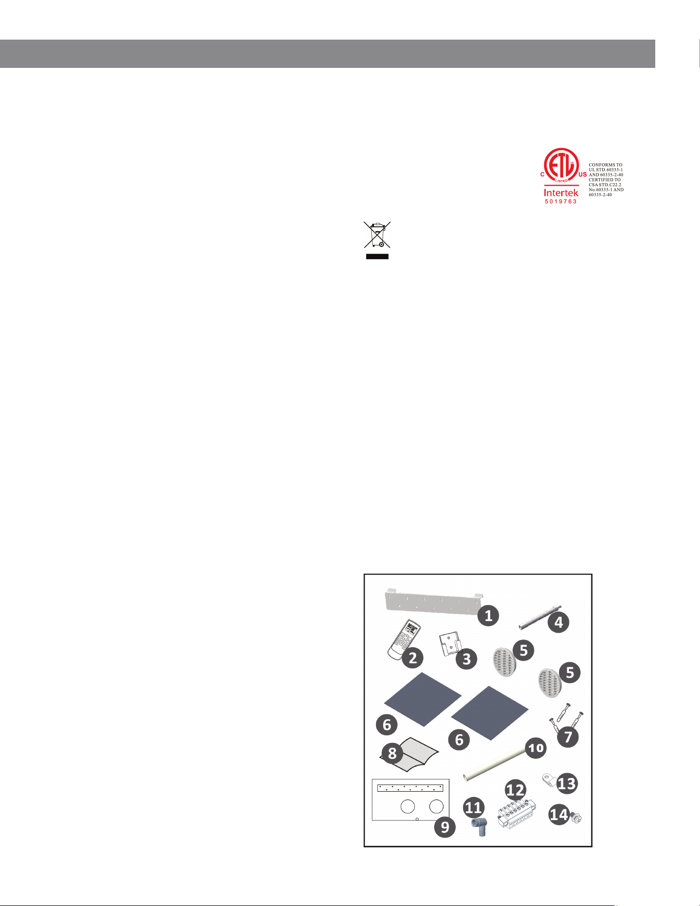
5. List of Accessories
Please refer to Diagram P0 for the appearance of each
of the listed accessories.
The following accessories are supplied with the unit:
1. Mounting bracket
2. Remote control
3. Remote control holder
4. Drain hose
5. Exterior grille(s)
6. Flexible air duct panel inserts
7. Screw kit
8. Instruction manual
9. Wall drilling template
10. Fresh air intake duct (18 in.)
11. Indoor drain adapter
12. Terminal connector (male end, pre-installed on 24V
thermostat wiring)
13. Cable clip
14. Screw for cable clip
Compliance and Certification
This product complies with applicable safety standards
and is ETL listed (Intertek) in accordance with:
• UL 60335-1
• UL 60335-2-40
• CSA C22.2 No. 60335-1
• CSA C22.2 No. 60335-2-40
Disposal and Environmental
Information
Electrical products must not be disposed of with
household waste.
Recycle this product at appropriate facilities where
available. Contact your local authority or retailer for
recycling information.
Batteries used in the remote control contain materials
that may be harmful to the environment.
Remove batteries at the end of their service life and
dispose of them in accordance with local regulations.
Electrical Supply Requirement
This product must be connected to a power supply
with a system impedance not exceeding 0.193 ohms.
If necessary, consult your local utility provider for
information regarding system impedance.
I. GENERAL INFORMATION
7
P0
8
I. GENERAL INFORMATION
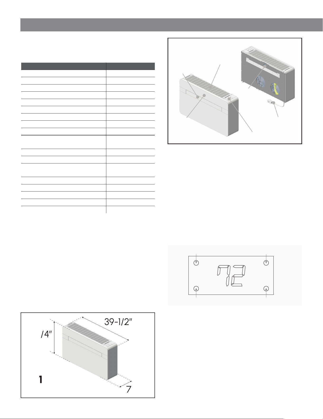
6. Technical Aspects (See P1, P2)
Model: PYM012GZUI16RD
* Specifications are subject to change without notice as part
of continuous product improvement.
22-3/4”
7-5/8”
39-1/2”
Parameter Value
Cooling Capacity (BTU/h) 11,800
Heating Capacity (BTU/h) 10,900
Electric Heat Capacity (BTU/h) 10,236
Rated Voltage / Frequency 208/230V, 60Hz
Rated Power – Cooling (W) 1,209
Rated Current – Cooling (A) 6.1
Rated Power – Heating (W) 947
Rated Current – Heating (A) 4.8
Rated Current – Electric Heater (A) 13.6
Rated Current – Heating + Electric
Heater (A)
—
Airflow (CFM) 330
Sound Level (dB(A)) 48 / 45 / 42
Temperature Setting Range
(Remote Control)
64–86°F
Refrigerant Type / Charge R32 / 22.9 oz
Global Warming Potential (GWP) 675
Dimensions (H × W × D) [inches] 22-3/4 × 39-1/2 × 7-5/8
Weight 117 lbs
PCBA Internal Fuse T20A 250VAC
Standard Test Conditions
P1
In accordance with ARI 310/380-2004
Cooling Mode Operating Range
• Indoor: 63°F to 90°F
• Outdoor: 63°F to 109°F
Heating Mode Operating Range
• Outdoor: 28°F to 75°F
• Indoor: 28°F to 81°F
Display Indicators
The display panel indicates system status and
temperature information.
Indicator Functions:
• Power indicator: Unit is powered on
• Night mode indicator: Night mode is active
• Compressor indicator: Compressor is operating
• Wi-Fi indicator:
▪ Flashing: Pairing mode
▪ Solid: Connected
Display Operation
The display shows both the set temperature and the
ambient room temperature.
After adjusting the temperature:
• The set temperature will flash approximately 15 times
• The display will then show the ambient temperature
for approximately 70 seconds
• After this period, the display will turn off until the next
adjustment is made
P2
Power cord
Filter grille
Onboard
system interface
Fresh air
intake system
Air directional
flap
Display
Panel
72
Power Indicator
Night Mode Indicator Compressor Indicator
Wi-Fi Indicator
9
I. GENERAL INFORMATION
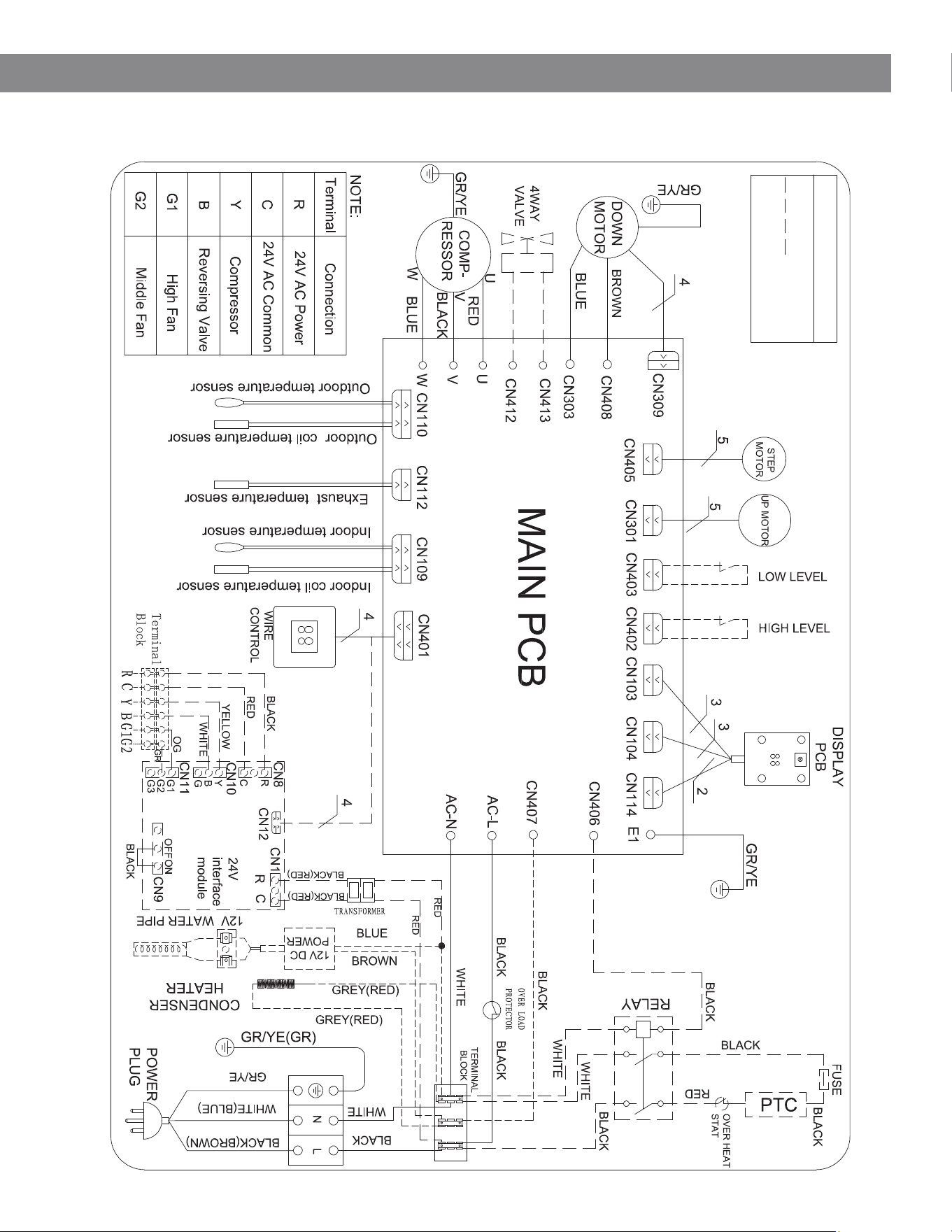
7. Control Board Layout
Wiring Description
Optional
10
II. INSTALLATION
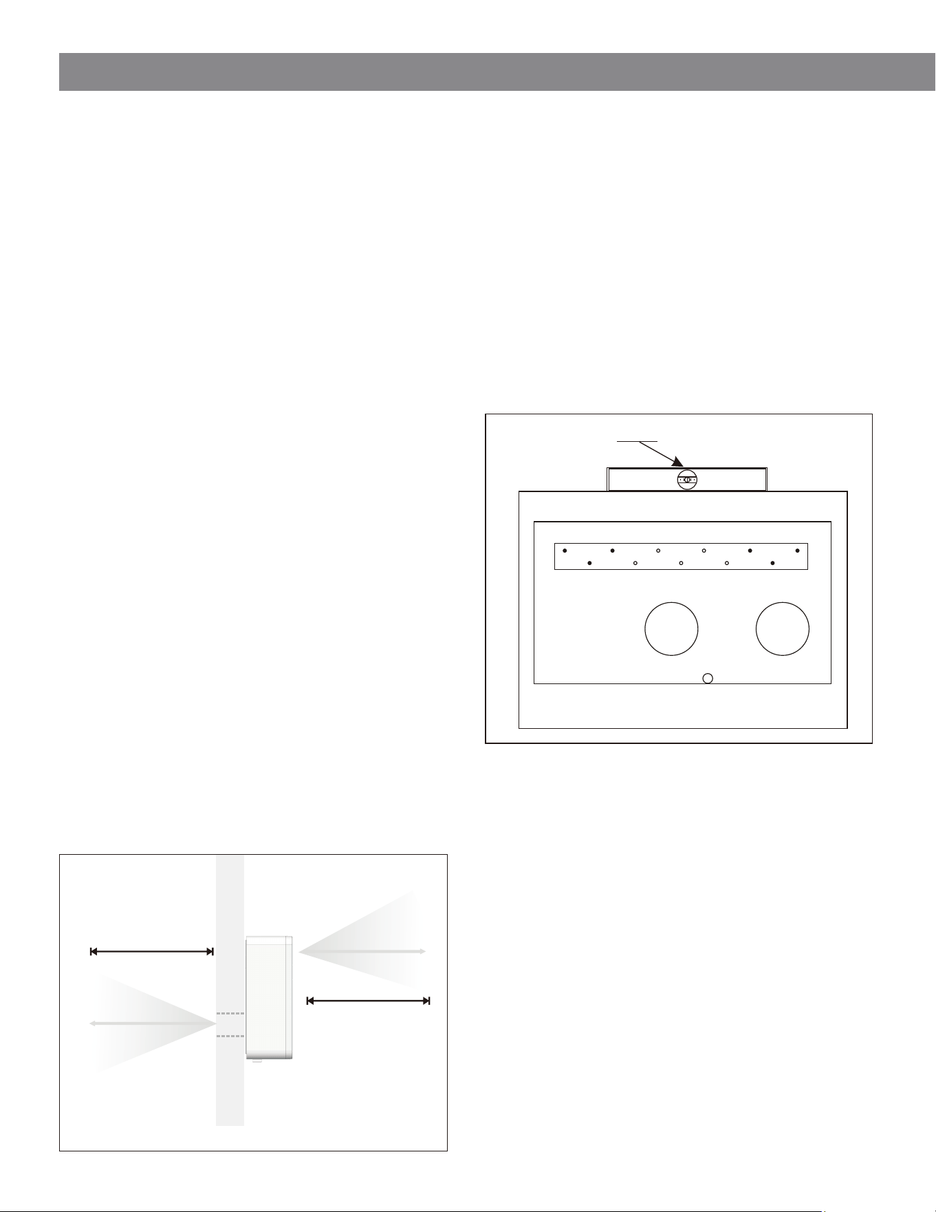
1. Unit Placement (Reference P3)
P3
Proper installation location is critical to ensure optimal
performance, safety, and reliability.
Follow all guidelines below carefully. Improper positioning
may result in reduced performance, installation issues, or
equipment damage.
Installation Requirements
• The unit must be installed on an exterior wall with
direct access to the outdoors.
• Maintain a minimum clearance of 6 ft on both the
indoor and outdoor sides of the unit.
• Maintain a minimum clearance of 6 ft from
combustible materials.
• Provide sufficient space around the unit as shown in
the installation template (P3).
• The mounting wall must be structurally sound and
capable of supporting the full weight of the unit.
Site Evaluation
Before installation, verify the following:
• The selected wall location can be drilled without
interfering with structural elements such as:
▪ Beams
▪ Columns
▪ Pipes
▪ Electrical wiring
• The exterior side of the wall is free from obstructions
that could restrict airflow, including:
▪ Vegetation (plants, leaves)
▪ Louvers or grilles
▪ Drain pipes or overflows
▪ Architectural features
Any obstruction may negatively impact system performance.
2. Wall Template Installation (P4)
Secure the supplied installation template to the wall only
after verifying all installation conditions.
Important Guidelines
• Do not drill any holes until you are certain that:
• No hidden obstructions are present inside the wall
• No electrical wiring, plumbing, or gas lines will be
affected
• Always use a level to ensure the unit is installed
perfectly level.
• Follow installation instructions carefully and
completely.
See Page 11 for Wall Template Layout.
Mounting Process for Packaged Heat Pump
Step 1 - Position Template
Attach the drilling template to the wall at the desired
installation location.
Step 2 - Level Template
Use a level to ensure the template is perfectly horizontal.
Step 3 - Mark Holes
Mark all mounting and duct openings.
Step 4 - Drill Openings
Drill holes according to the dimensions shown.
6 ft
6 ft
Outdoor Indoor
P4
Level
11
II. Installation
Minimum
8 inches
Minimum
8 inches
Minimum
6 inches
Minimum
6 inches
Minimum 4 inches
Outdoor Air Intake
IMPORTANT
Install the unit level to ensure proper drainage and operation.
Mounting Bracket Layout
Additional Mounting Points (for drywall or weak walls)
Required Mounting Points
Outdoor Air Exhaust
Fresh Air Intake
Minimum 4 inches
Minimum
6 inches
Minimum
6 inches
22-7/8”
18”
7-1/4”
2”
1-1/4”
8”
16-3/4”
4-7/8”
2-3/8”
3-3/4”
8”
12-5/8”
17-3/4”
2”
2-1/4”
39-3/8”
Condensate Drain
Wall Drilling Template (P4)
Use this template to mark and drill all required wall openings before mounting the unit.
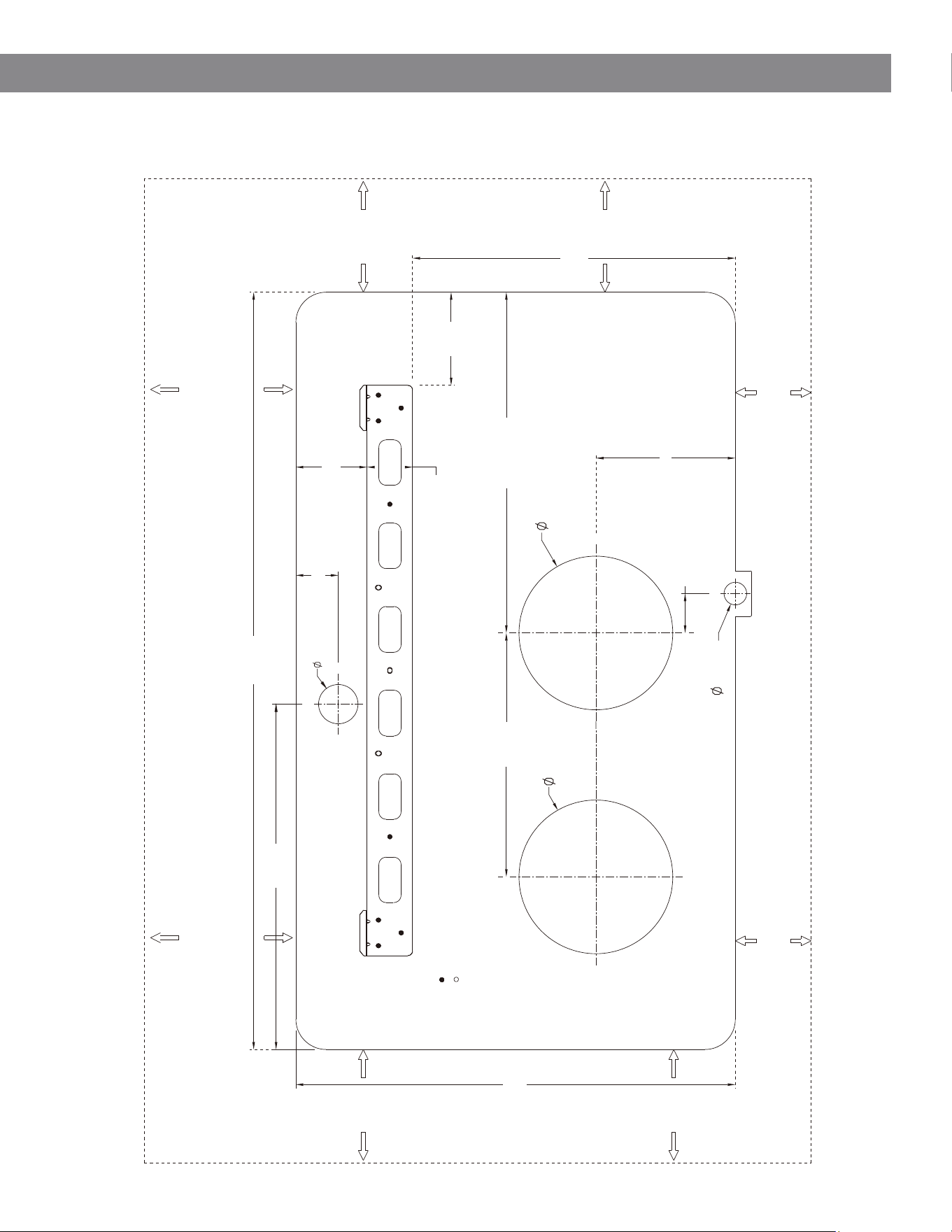
11
II. Installation
Minimum
8 inches
Minimum
8 inches
Minimum
6 inches
Minimum
6 inches
Minimum 4 inches
Outdoor Air Intake
IMPORTANT
Install the unit level to ensure proper drainage and operation.
Mounting Bracket Layout
Additional Mounting Points (for drywall or weak walls)
Required Mounting Points
Outdoor Air Exhaust
Fresh Air Intake
Minimum 4 inches
Minimum
6 inches
Minimum
6 inches
22-7/8”
18”
7-1/4”
2”
1-1/4”
8”
16-3/4”
4-7/8”
2-3/8”
3-3/4”
8”
12-5/8”
17-3/4”
2”
2-1/4”
39-3/8”
Condensate Drain
Wall Drilling Template (P4)
Use this template to mark and drill all required wall openings before mounting the unit.
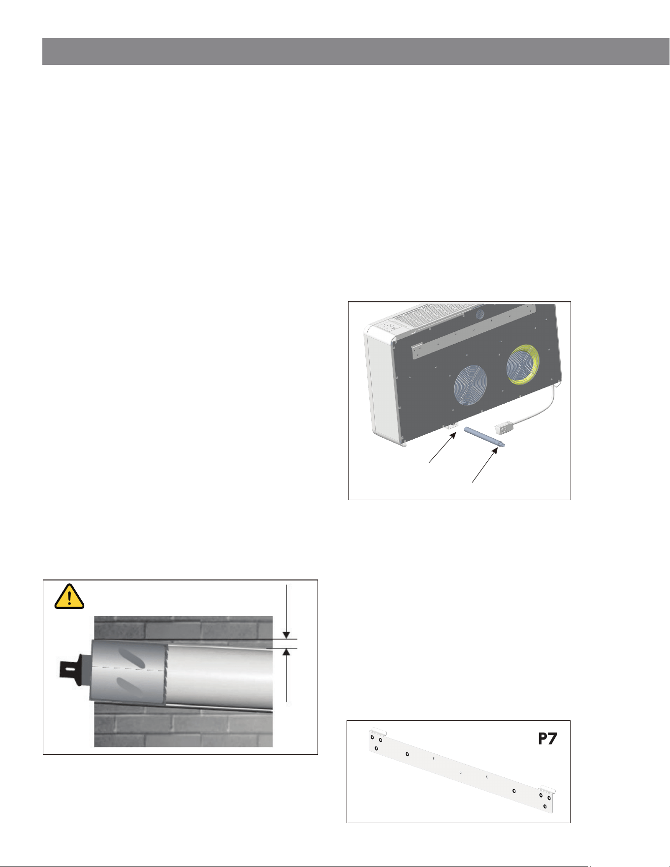
12
II. INSTALLATION
3. Drilling the Wall (Reference P5)
IMPORTANT:
When drilling through an exterior wall above ground level,
ensure the work area is secure and that the exterior side is
supervised during drilling.
Air Intake and Exhaust Openings
Use appropriate tools for wall penetration, such as:
• Diamond core drill
• Core boring bit with adjustable speed and high torque
Procedure
1. Secure the drilling template (P4) to the wall.
2. Verify all measurements and confirm the template is
level.
3. Mark the center of each hole using a pilot drill.
4. Drill two Ø8" holes for:
A. Outdoor Air Intake
B. Outdoor Air Exhaust
IMPORTANT - Hole Slope
The wall penetrations must be drilled with a downward
slope toward the exterior.
• Recommended slope: 3° to 5°.
• Purpose: Prevent water from entering the indoor
space.
WARNING
All wall penetrations must be properly sealed and
waterproofed after installation to prevent water ingress.
4. Condensate Drain (Ref. P6)
This unit uses a gravity-assisted condensate drainage
system.
Requirements
• Drill a Ø1-1/4" hole in the location shown on the
template (P4).
• Ensure drainage is directed outdoors.
Drain Line Installation
• Connect the drain pipe to the unit’s drain outlet
(bottom of the chassis).
• Maintain a minimum downward slope of 3° along the
entire drain line.
• Avoid traps, dips, or upward runs in the drain line.
5. Mounting the Bracket (Ref. P7)
Secure the mounting bracket to the wall using
appropriate fasteners.
Procedure
1. Drill mounting holes using the template (P4):
A. Use required fastener locations (primary holes)
B. Use additional fastener locations if the wall is
not structurally solid
2. The supplied anchors require approximately:
A. 5/16" (8 mm) diameter holes
3. Verify that the wall structure is suitable for anchoring:
A. Concrete / masonry → standard anchors
B. Stud wall → fasten into studs where possible
P5
3° INCLINATION
3°
Indoor Outdoor
P6
To: Flexible hose
(rubber connection)
To: Rigid pipe (PVC connection)
P7
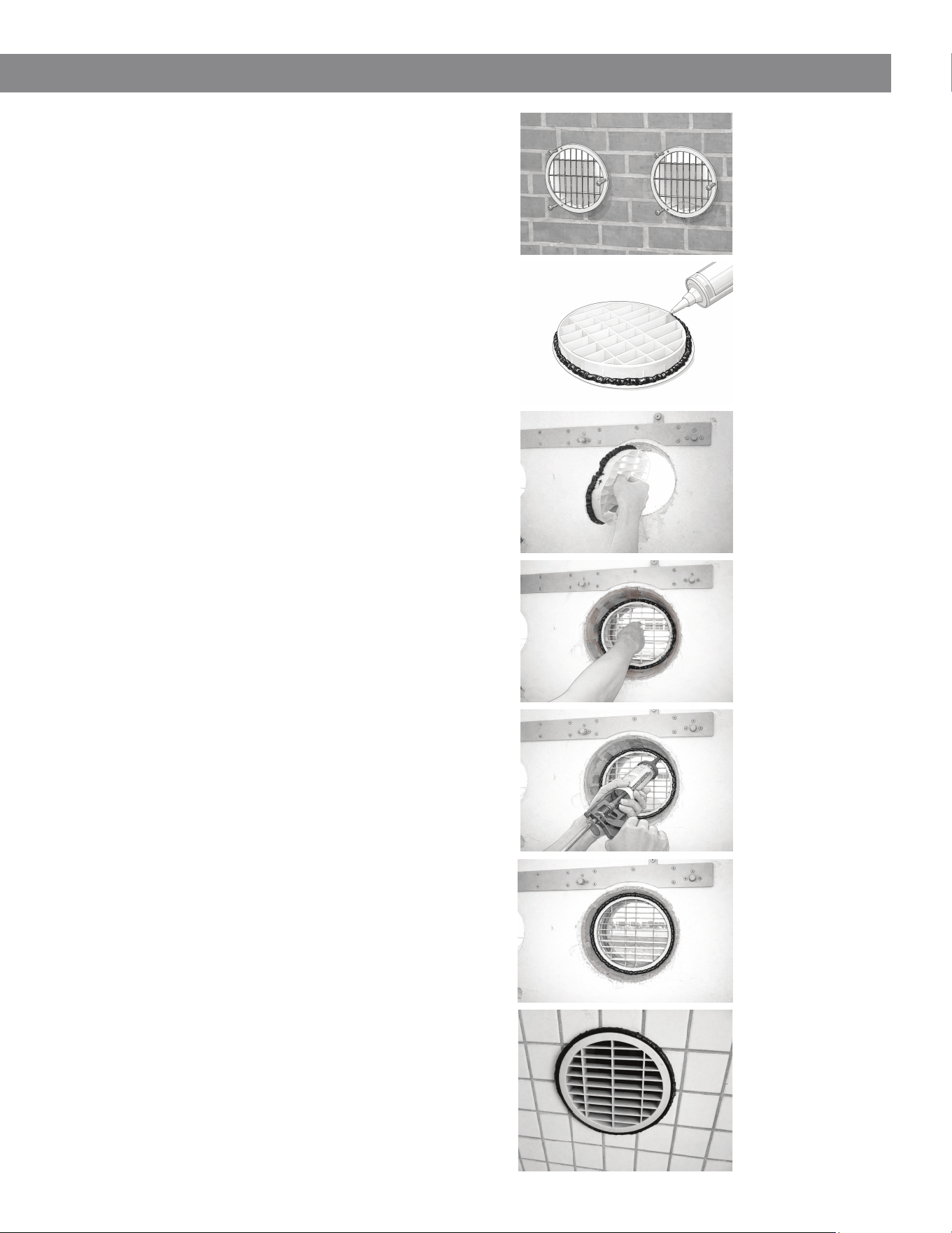
13
II. Installation
5. Installing the Exterior Grilles
WARNING
Apply proper waterproofing/sealing to the exterior wall
before installing the grilles to prevent water intrusion into
the indoor space.
General Installation
After drilling the wall openings, install the supplied
exterior grilles.
Method 1 - Installation from Outside
(Preferred)
If the exterior wall is accessible:
1. Position the grille over the wall opening.
2. Ensure the grille fins are oriented vertically.
3. Secure the grille to the wall using:
A. Wall anchors (plugs)
B. Screws (approx. 1/4" / 6 mm diameter)
Ensure the grille is installed with airflow direction
matching the intake/exhaust configuration shown in the
template. Refer to Fig. P8.
Method 2 - Installation from Inside (Limited
Exterior Access)
If the exterior side is not accessible:
1. Apply a continuous bead of sealant (silicone) around
the outer edge of the grille.
2. Gently compress or fold the grille as needed.
3. Insert the grille through the wall opening from inside.
4. Carefully position and pull the grille into place so it
seats properly on the exterior wall.
This may require patience and adjustment to ensure
proper alignment. Refer to Fig. P9–P11.
Sealing the Grille
After the grille is installed:
1. Apply additional exterior-grade sealant around the
perimeter between the grille and the wall.
2. Ensure a continuous seal to prevent water ingress.
Refer to Fig. P12-P13.
Sealant Recommendation
The sealant shown in the illustrations is for reference only.
Use white or clear exterior-grade silicone sealant for best
appearance and durability. Refer to Fig. P14.
P8
P9
P10
P11
P12
P13
P14
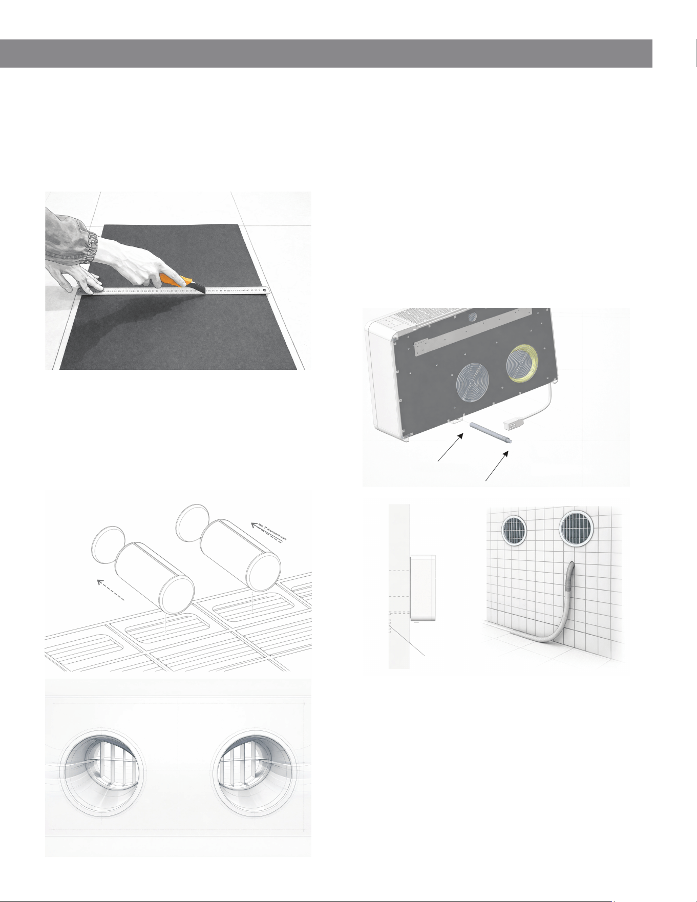
14
II. Installation
6. Installation of Air Duct Pipes
After drilling the wall openings, install the supplied plastic
air ducts as follows:
• Measure the wall thickness and cut the plastic duct
sleeves to the appropriate length.
• Roll the sheet into a cylindrical shape and insert it into
each wall opening. If desired, use a strip of adhesive
tape to maintain the air duct tubing shape.
• Ensure the seam of the duct is positioned at the top
(12 o’clock position).
• Maintain a slight downward slope (minimum 3°)
consistent with the drilled holes.
• Insert the rolled ducts in place within the wall holes.
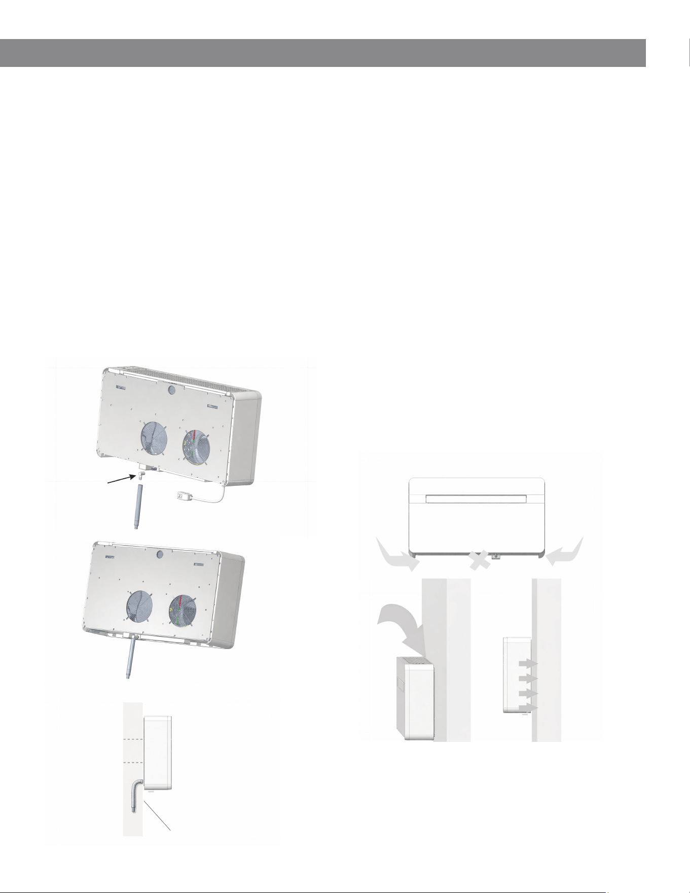
7. Connecting the Drainage Pipe
Connect the drain line from the unit to ensure proper
condensate removal:
• Attach the flexible drain hose to the drain outlet
located at the bottom of the unit chassis.
• Use the appropriate rigid connector if required to
secure the connection.
Note:
In standard or warm climates, route the drain line to
discharge outdoors at a suitable location. Ensure the line
maintains a continuous downward slope for proper
drainage. (See P17)
P16
P15
P17
Outdoor
Indoor
To: Drain Stub
To: Rigid Connector (PVC)
Drainage Line
15
II. InstallationII. Installation
8. Cold Climate Drain Configuration
In cold climate installations, the condensate drain line
may be subject to freezing. To prevent blockage or
damage, the drain line may be routed within the wall
cavity and discharged at an appropriate interior or
protected location.
• Connect the indoor drainage adapter to the unit’s
condensate outlet.
• Route the drain pipe downward, maintaining a
continuous slope for proper drainage.
• Ensure the discharge point is suitable and complies
with local building practices.
Refer to Fig. P18 for recommended configurations.
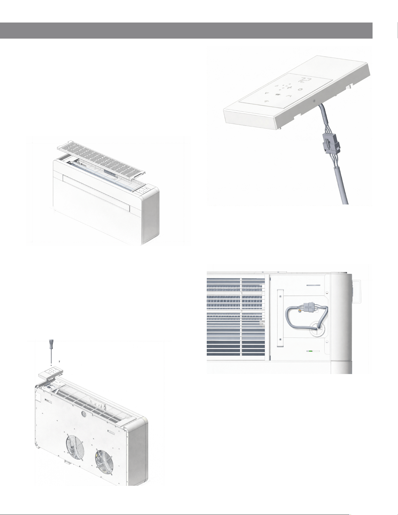
9. Mounting Unit on Wall Bracket
Indoor
Drainage
Adapter
(1)
P18
P19
P20
(2)
(3)
Drainage Pipe
Indoor
Outdoor
After confirming that the mounting bracket is securely
fastened to the wall, and that all electrical and drainage
preparations have been completed, proceed with
installing the unit.
1. Lift and Position
Lift the unit by holding the lower sides of the
chassis. Slightly tilt the unit toward you to align it
with the mounting bracket.
2. Engage the Bracket
Hook the unit onto the bracket and gently lower it
into place. Ensure the unit is properly seated.
3. Secure Against the Wall
Press the unit firmly against the wall. Verify the
following:
▪ The rear insulation panel is seated with no gaps
▪ No obstructions or misalignment are present
▪ The rear air channels are properly aligned with
the wall openings
4. Drain and Duct Alignment
Confirm that the rear plastic air ducts are
correctly inserted into the wall sleeves and that
the drain line is properly positioned.
Refer to Figs. P19 and P20 for lifting points and installation
orientation.
Important Installation Notes
• Do not install the unit in high-humidity environments
such as laundry rooms.
• Ensure the electrical plug remains accessible after
installation.
• Installation must comply with all applicable national
and local electrical codes.
Lift Here
Lift Here
16
II. Installation
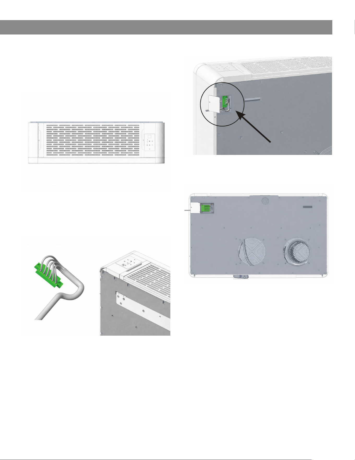
10. Configuring External 24V Wall
Thermostat Operation
This unit can be configured for control via an external
24V wall thermostat by connecting the supplied adapter
interface.
Step 1 - Remove the Top Grille Assembly
Carefully remove the top grille to access the internal
control components.
Step 2 - Disconnect the Internal Control Module
• Loosen the mounting screws securing the touchscreen
control module.
• Gently lift and remove the control module.
• Disconnect the wiring harness by separating the
control module’s plug (male connector) from the
main PCB socket (female connector).
Refer to Figures 2-1 and 2-2.
Step 3 - Connect the 24V Adapter Harness
• Connect the 24V adapter harness (male connector)
to the main PCB socket (female connector).
• Ensure the connection is fully seated and secure.
Important Notes
• Handle all connectors carefully to avoid damage to
pins or wiring.
• Do not force connections; verify proper alignment
before insertion.
• Ensure all wiring is routed safely and does not
interfere with moving components or panel
reinstallation.
2-1
2-2
17
II. Installation
10. Configuring External 24V Wall
Thermostat Operation
Step 4 - Reinstall Internal Components
Reinstall the touchscreen control module and secure
it in place. Reattach the top grille assembly.
Step 5 - Connect Thermostat Wiring
• Connect the 24V wall thermostat wiring to the
provided terminal (male connector).
• Match the wiring according to the terminal markings.
• Ensure all connections are fully seated and locked in
place.
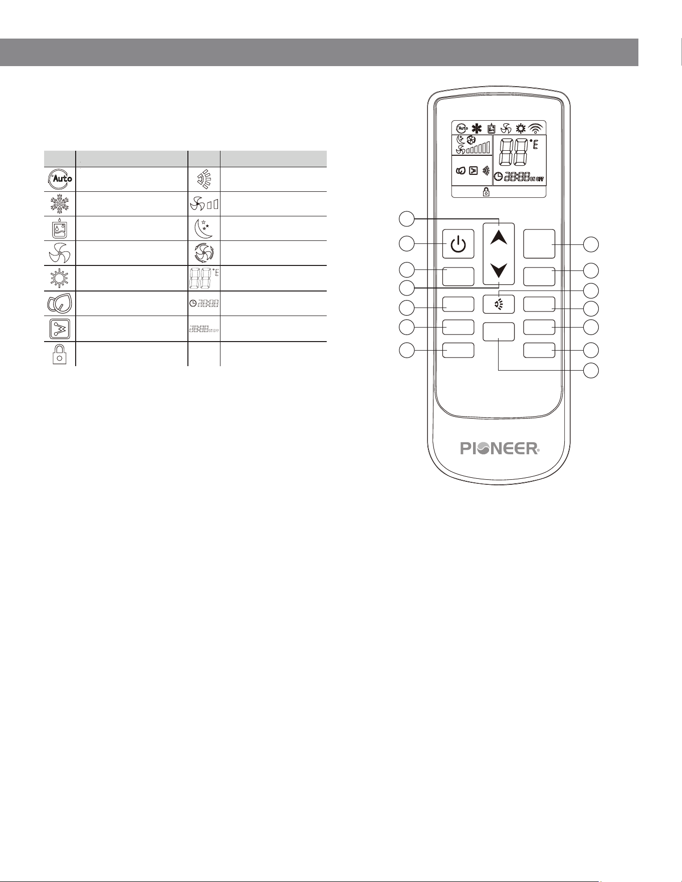
Step 6 - Route and Secure Thermostat Cable
• Remove the small metal access cover located on the
upper left side of the rear panel.
• Insert the thermostat wire terminal (male connector)
into the corresponding rear panel terminal (female
connector).
• Secure the thermostat cable using the provided cable
clip and screw.
• Ensure the cable is properly routed and free from
strain or interference.
Step 7 - Reinstall Rear Cover
• Reinstall the metal access cover.
• External thermostat configuration is now complete.
Important Notes
1. Included Components
The thermostat terminal (male connector), cable clip,
and mounting screw are included with the unit’s
accessory kit.
2. Control Behavior After Conversion
After enabling external thermostat operation:
• The unit’s onboard display and touchscreen controls
will be disabled
• The handheld remote control will no longer function
• The front panel display and indicator lights will remain
off during operation
• In the event of a fault, the front panel display will
illuminate to show the error code
3. Electrical Safety
All installation and wiring procedures must be
performed with power disconnected. Ensure the unit
is fully de-energized before beginning work.
18
III. Usage and Maintenance
1. LCD Icon Overview
The display uses the following icons to indicate operating
modes and system status:
1
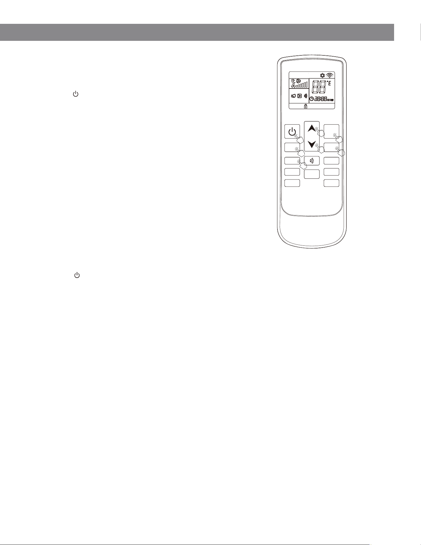
2. Remote Control Functions
Each button on the remote control corresponds to a specific function:
1. MODE: Selects the operating mode (Auto, Cool, Dry, Fan, Heat).
2. FAN SPEED (Increase): Increases the fan speed setting.
3. LOUVER SWING: Adjusts the airflow direction.
4. SLEEP: Automatically adjusts the set temperature for improved comfort during sleep.
5. TIMER: Sets the unit’s automatic start and stop times.
6. LIGHT (Optional): Turns the display light on or off (if equipped).
7. TEMP (°C / °F): Switches the temperature unit between Celsius and Fahrenheit.
8. UP (▲): Increases the set temperature or adjusts time settings.
9. ON/OFF: Turns the unit on or off.
10. FAN SPEED (Decrease): Decreases the fan speed setting.
11. DOWN (▼): Decreases the set temperature or adjusts time settings.
12. ELECTRIC HEATER (Optional): Activates the integrated electric heater to assist heating performance.
13. CLOCK: Sets or adjusts the system clock.
14. LOCK: Locks or unlocks the remote control to prevent unintended operation.
* Optional features may not be available on all models.
Refer to the illustration for button locations
*
*
FAN- FAN+
MODE
HEATER SLEEP
CLOCK TIMER
LOCK
LIGHT
°C / °F
Icon Description Icon Description
Automatic Operation Airflow Direction
Cooling Mode Fan Speed Level
Dehumidification Mode Sleep Mode
Fan-Only Operation Automatic Fan Speed
Heating Mode
Set Temperature
Display
Display Light (Optional) Time Display
Auxiliary Electric Heater
(Optional)
Timer Function
Control Lock Enabled - -
9
10
12
13
14
11
2
4
5
6
3
7
8
19
III. Usage and Maintenance
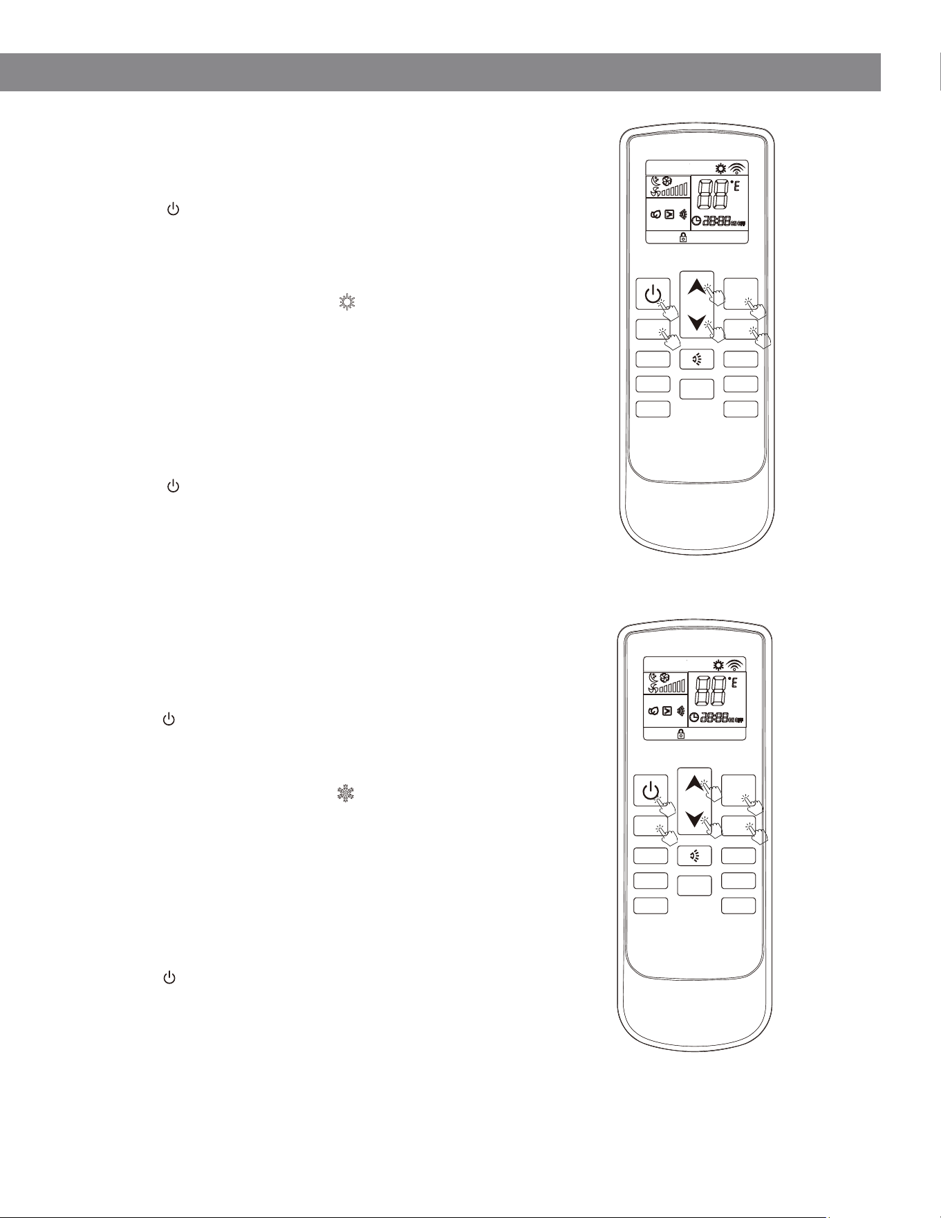
3. Heating Mode
Operating Sequence
1. Power On
Press ON/OFF to turn the unit on. The system will
resume the last operating state (memory
function).
2. Select Heating Mode
Press MODE and select Heating ( / heat icon).
3. Set Temperature
Use / (UP / DOWN) to adjust the desired
temperature.
4. Adjust Fan Speed
Press FAN SPEED (+ / −) to select airflow level:
◦ Low
◦ Medium
◦ High
◦ Auto
5. Power Off
Press ON/OFF to turn the unit off.
The current settings will be retained for the next
startup.
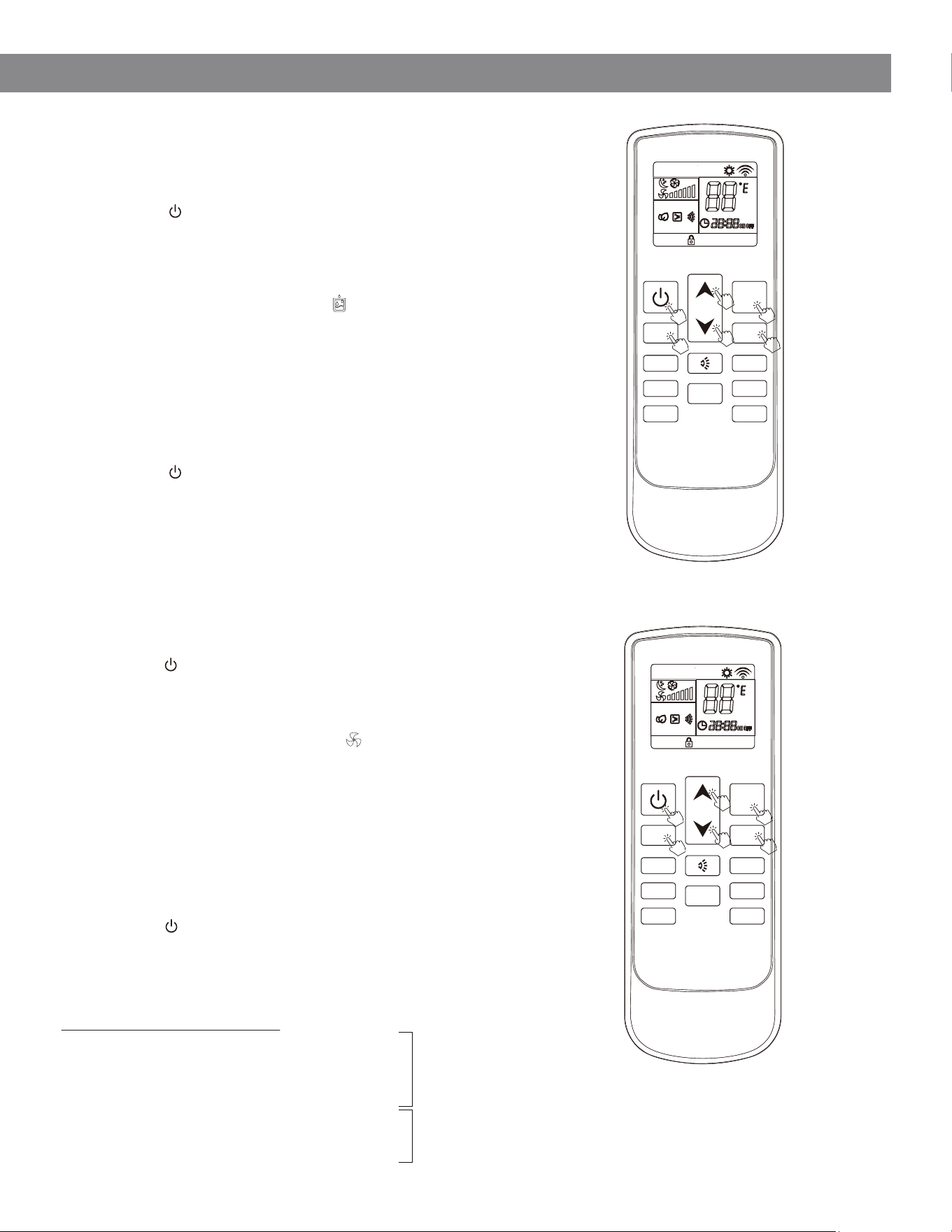
4. Cooling Mode
▲
Operating Sequence
1. Power On
Press ON/OFF to turn the unit on. The system will
resume the previous operating state.
2. Select Cooling Mode
Press MODE and select Cooling ( / icon).
3. Set Temperature
Use / (UP / DOWN) to adjust the desired
temperature.
4. Adjust Fan Speed
Press FAN SPEED (+ / −) to select airflow level:
◦ Low
◦ Medium
◦ High
◦ Auto
5. Power Off
Press ON/OFF to turn the unit off.
The selected settings will be stored for future
operation.
Notes
• The unit may require several minutes to reach stable
heating or cooling output.
• In heating mode, a brief delay may occur before
warm air is discharged (normal operation).
▲
▲
▲
FAN- FAN+
MODE
HEATER SLEEP
CLOCK TIMER
LOCK
LIGHT
0
C /
0
F
FAN- FAN+
MODE
HEATER SLEEP
CLOCK TIMER
LOCK
LIGHT
0
C /
0
F
20
DRY MODE
FAN MODE
III. Usage and Maintenance
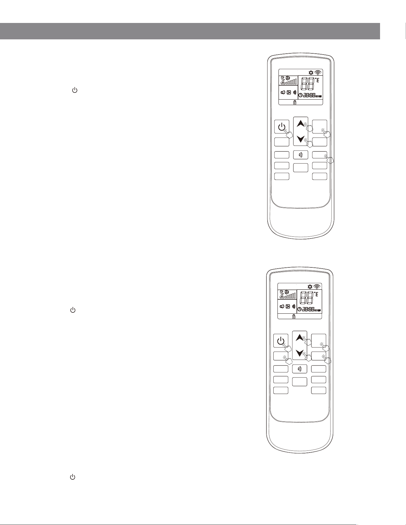
5. Dry Mode (Dehumidification)
Operating Sequence
1. Power On
Press ON/OFF to turn the unit on. The system will
resume the last operating state (memory
function).
2. Select Dry Mode
Press MODE and select Drying( / dry icon).
3. Set Temperature
Use / (UP / DOWN) to adjust the desired
temperature.
4. Adjust Fan Speed
In Dry mode, the fan speed is automatically
controlled and cannot be adjusted.
The indoor fan will operate at a low speed to
maximize moisture removal.
5. Power Off
Press ON/OFF to turn the unit off.
The current settings will be retained for the next
startup.
6. Fan Only Mode
▲
Operating Sequence
1. Power On
Press ON/OFF to turn the unit on. The system will
resume the previous operating state.
2. Select Fan Mode
Press MODE and select Fan Only( / icon).
3. Set Temperature
Use / (UP / DOWN) to adjust the desired
temperature.
4. Adjust Fan Speed
Press FAN SPEED (+ / −) to select airflow level:
◦ Low
◦ Medium
◦ High
◦ Auto
5. Power Off
Press ON/OFF to turn the unit off.
The selected settings will be stored for future
operation.
Expected Behavior Notes
• The unit prioritizes moisture removal over
temperature control
• The fan operates at low speed by design
• Light cooling may occur during operation
• No heating or cooling is performed
• Temperature setting has no effect
• This mode is intended for air circulation only
▲
▲
▲
FAN- FAN+
MODE
HEATER SLEEP
CLOCK TIMER
LOCK
LIGHT
0
C /
0
F
FAN- FAN+
MODE
HEATER SLEEP
CLOCK TIMER
LOCK
LIGHT
0
C /
0
F
21
III. Usage and Maintenance
7. Sleep Mode
Operating Sequence
1. Power On
Press ON/OFF to turn the unit on. The system will
resume the last operating state (memory
function).
2. Select Operating Mode
Press the MODE button and select Cooling,
Heating, or Auto mode.
Sleep mode operates in conjunction with these
modes.
3. Set Temperature
Use / (UP / DOWN) to adjust the desired
temperature.
4. Activate Sleep Mode
Press the SLEEP button. The Sleep icon will
appear on the display, indicating that Sleep
mode is active.
Press the SLEEP button again to cancel Sleep
mode.
5. Fan Operation
When Sleep mode is active, the indoor fan
operates at a low, consistent speed to reduce
noise and improve comfort.
8. Auto Mode
Operating Sequence
1. Power On
Press ON/OFF to turn the unit on. The system will
resume the previous operating state.
2. Select Auto Mode
Press the MODE button and select Auto mode.
The unit will automatically determine the
appropriate operating mode.
3. Automatic Operation
The system continuously monitors room
temperature and automatically switches
between:
◦ Cooling
◦ Heating
◦ Fan
to maintain the set temperature.
4. Adjust Fan Speed
Press FAN SPEED (+ / −) to select airflow level:
◦ Low
◦ Medium
◦ High
◦ Auto
5. Power Off
Press ON/OFF to turn the unit off. The selected
settings will be stored for future operation.
▲
▲
FAN- FAN+
MODE
HEATER SLEEP
CLOCK TIMER
LOCK
LIGHT
0
C /
0
F
FAN- FAN+
MODE
HEATER SLEEP
CLOCK TIMER
LOCK
LIGHT
0
C /
0
F
22
III. Usage and Maintenance
9. Timer Off Function
Operating Sequence
1. Power On
Press ON/OFF to turn the unit on. The system will
resume the last operating state (memory
function).
2. Select Dry Mode
Press the MODE button and choose the desired
operating mode.
3. Set Temperature
Use / (UP / DOWN) to adjust the desired
temperature.
4. Set Timer Off
▪ Press the TIMER button to initiate TIMER OFF function
▪ Use UP ( ) or DOWN ( ) to set the desired shut-off
time
▪ Time adjusts in increments (per model configuration)
▪ Press TIMER again to confirm
When the set time is reached, the unit will automatically turn off.
Press the TIMER button again before the countdown ends to
cancel the Timer Off function.
Expected Behavior Notes
• The unit continues operating normally until the timer expires
• Timer Off overrides manual operation at the scheduled time
• Canceling the timer returns the unit to normal operation
10. Timer On Function
Operating Sequence
1. Power Off
Ensure the unit is turned OFF.
2. Set Timer On
▪ Press the TIMER button to enter Timer On
settings.
▪ Use UP ( ) or DOWN ( ) to set the desired start
time
▪ Configure the desired MODE, TEMPERATURE,
and FAN SPEED
▪ Press TIMER again to confirm
When the set time is reached, the unit will automatically
start with the selected settings.
Press the TIMER button again before activation to cancel
the Timer On function.
Expected Behavior Notes
• The unit remains off until the scheduled start time
• The system starts using the pre-configured settings
• Timer On can be canceled at any time before
activation
▲
▲
▲
▲
▲
FAN- FAN+
MODE
HEATER SLEEP
CLOCK TIMER
LOCK
LIGHT
0
C /
0
F
FAN- FAN+
MODE
HEATER SLEEP
CLOCK TIMER
LOCK
LIGHT
0
C /
0
F
▲
23
III. Usage and Maintenance
11. Electric Heater Function (Optional)
Operating Sequence
1. Power On
Press ON/OFF to turn the unit on. The system will
resume the last operating state (memory
function).
2. Select Heating Mode
Press the MODE button and select Heating mode.
3. Set Temperature
Use / (UP / DOWN) to adjust the desired
temperature.
4. Activate Sleep Mode
Press FAN SPEED (+ / −) to select airflow level:
◦ Low
◦ Medium
◦ High
◦ Auto
5. Activate Electrical Heater
▪ Press the HEATER button to enable the auxiliary
electric heater.
▪ The heater icon will appear on the display when
active.
▪ Press the HEATER button again to turn the
function off.
6. Power Off
▪ Press the ON/OFF button to turn the unit off.
▪ The system will retain the selected settings for
the next startup.
Expected Behavior
• The electrical heater provides supplemental heating
to improve performance in low ambient conditions
• This function operates only in Heating mode
• Power consumption increases when the electrical
heater is active
• The unit may automatically cycle the heater on and
off to maintain the set temperature
Important Notes
• This feature is model-dependent and may not be
available on all units
• The electrical heater is intended as an auxiliary heat
source, not a primary heating system
• Ensure the unit is installed on an appropriate
electrical circuit capable of supporting increased load
▲
▲
FAN- FAN+
MODE
HEATER SLEEP
CLOCK TIMER
LOCK
LIGHT
0
C /
0
F
23
III. Usage and Maintenance
11. Electric Heater Function (Optional)
Operating Sequence
1. Power On
Press ON/OFF to turn the unit on. The system will
resume the last operating state (memory
function).
2. Select Heating Mode
Press the MODE button and select Heating mode.
3. Set Temperature
Use / (UP / DOWN) to adjust the desired
temperature.
4. Activate Sleep Mode
Press FAN SPEED (+ / −) to select airflow level:
◦ Low
◦ Medium
◦ High
◦ Auto
5. Activate Electrical Heater
▪ Press the HEATER button to enable the auxiliary
electric heater.
▪ The heater icon will appear on the display when
active.
▪ Press the HEATER button again to turn the
function off.
6. Power Off
▪ Press the ON/OFF button to turn the unit off.
▪ The system will retain the selected settings for
the next startup.
Expected Behavior
• The electrical heater provides supplemental heating
to improve performance in low ambient conditions
• This function operates only in Heating mode
• Power consumption increases when the electrical
heater is active
• The unit may automatically cycle the heater on and
off to maintain the set temperature
Important Notes
• This feature is model-dependent and may not be
available on all units
• The electrical heater is intended as an auxiliary heat
source, not a primary heating system
• Ensure the unit is installed on an appropriate
electrical circuit capable of supporting increased load
▲
▲
FAN- FAN+
MODE
HEATER SLEEP
CLOCK TIMER
LOCK
LIGHT
0
C /
0
F
24
III. Usage and Maintenance
12. Onboard Control Functions
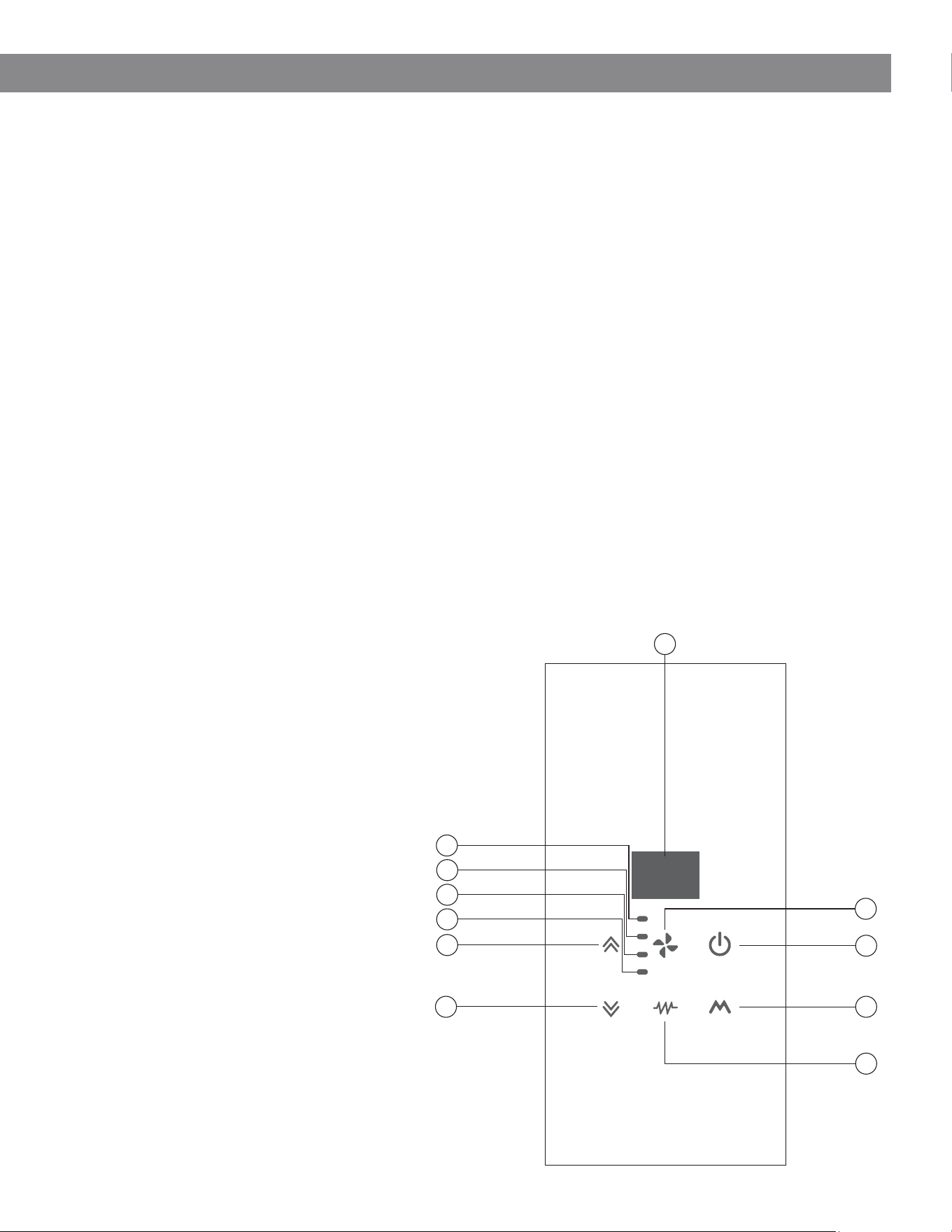
The unit is equipped with onboard controls for basic operation when the remote control is unavailable.
Control Panel Overview
1. ON/OFF Button: Turns the unit on or off.
2. MODE Button: Selects the operating mode (Cooling, Heating, Fan, Auto, etc.).
3. ELECTRICAL HEATER Button: Enables or disables the auxiliary electric heater.
4. FAN SPEED Button: Adjusts the indoor fan speed.
5. DOWN (▼) Button: Decreases the set temperature or adjusts time settings.
6. UP (▲): Increases the set temperature or adjusts time settings.
7. HIGH SPEED Indicator: Illuminates when the fan is operating at high speed.
8. MEDIUM SPEED Indicator: Illuminates when the fan is operating at medium speed.
9. LOW SPEED Indicator: Illuminates when the fan is operating at low speed.
10. AUTO FAN Indicator: Illuminates when fan speed is set to automatic.
11. Temperature Display Window: Displays system status and temperature information.
Display Behavior
• The display shows both the set
temperature and room (ambient)
temperature
• When the temperature is adjusted, the
set temperature briefly flashes
• After a short interval, the display returns
to showing the ambient temperature
• The display may turn off after a period
of inactivity and will reactivate upon user
input
1
2
5
6
7
8
9
10
11
3
4
24
III. Usage and Maintenance
12. Onboard Control Functions
The unit is equipped with onboard controls for basic operation when the remote control is unavailable.
Control Panel Overview
1. ON/OFF Button: Turns the unit on or off.
2. MODE Button: Selects the operating mode (Cooling, Heating, Fan, Auto, etc.).
3. ELECTRICAL HEATER Button: Enables or disables the auxiliary electric heater.
4. FAN SPEED Button: Adjusts the indoor fan speed.
5. DOWN (▼) Button: Decreases the set temperature or adjusts time settings.
6. UP (▲): Increases the set temperature or adjusts time settings.
7. HIGH SPEED Indicator: Illuminates when the fan is operating at high speed.
8. MEDIUM SPEED Indicator: Illuminates when the fan is operating at medium speed.
9. LOW SPEED Indicator: Illuminates when the fan is operating at low speed.
10. AUTO FAN Indicator: Illuminates when fan speed is set to automatic.
11. Temperature Display Window: Displays system status and temperature information.
Display Behavior
• The display shows both the set
temperature and room (ambient)
temperature
• When the temperature is adjusted, the
set temperature briefly flashes
• After a short interval, the display returns
to showing the ambient temperature
• The display may turn off after a period
of inactivity and will reactivate upon user
input
1
2
5
6
7
8
9
10
11
3
4
25
III. Usage and Maintenance
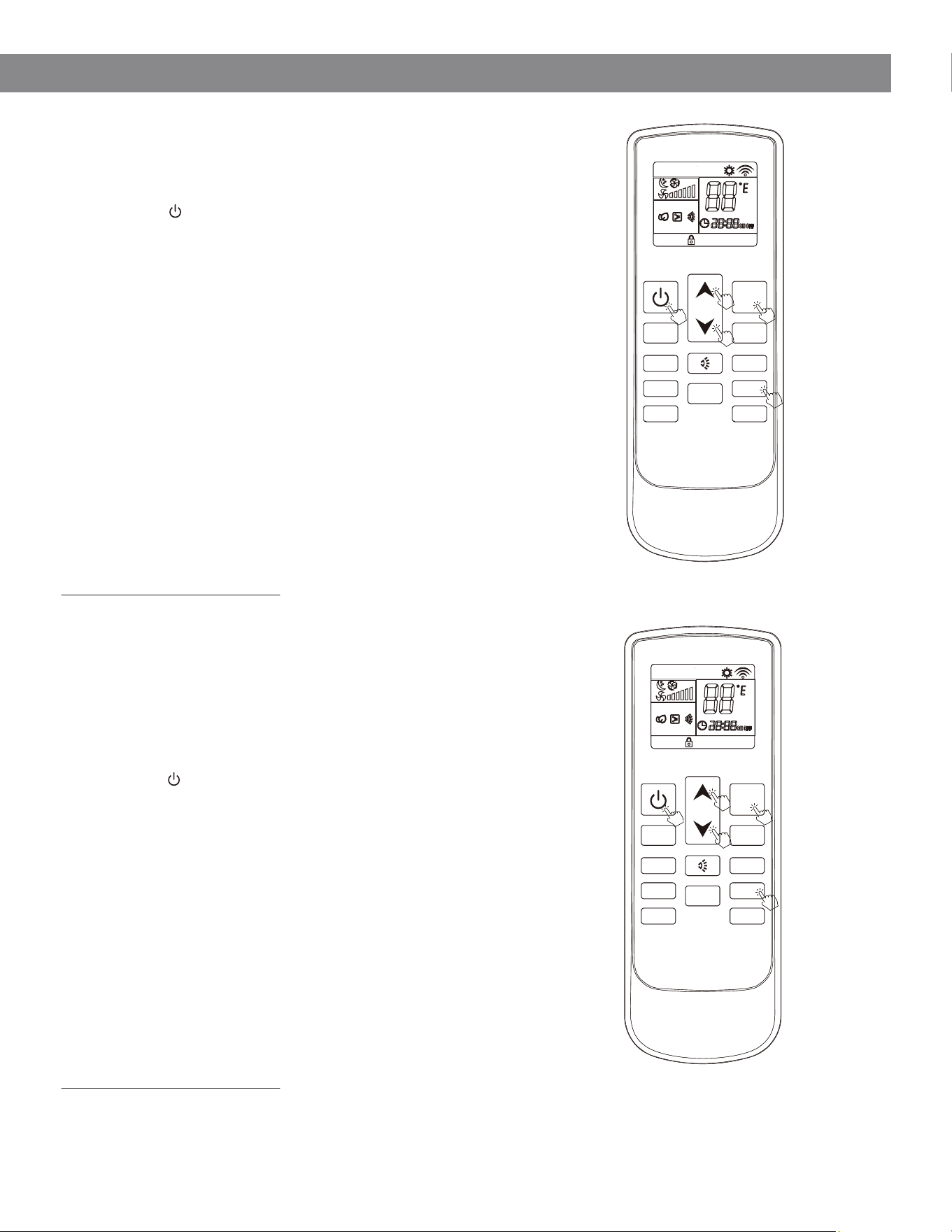
13. Wi-Fi Connection & App Setup
Download the App
Download the Pioneer Airlink app from your device’s
app store, or scan the QR code provided.
Account Setup
• Create an account and log in
• Add your device within the app
• Connect to your local Wi-Fi network by following the
on-screen instructions
•
Wi-Fi Pairing
1. Enter Pairing Mode
Press the LOUVER SWING button on the remote
five times within 5 seconds to enter pairing mode.
◦ First-time pairing: indicator flashes slowly
2. Switch Pairing Mode (if needed)
Press the LOUVER SWING button five times again
within 5 seconds to switch to fast flashing mode
3. Complete Pairing
Follow the app instructions to complete
connection
4. Clear Pairing
After successful pairing, press the LOUVER
SWING button five times within 5 seconds to reset
or clear Wi-Fi pairing
Wi-Fi Control
Once connected, the unit can be controlled remotely
through the mobile app.
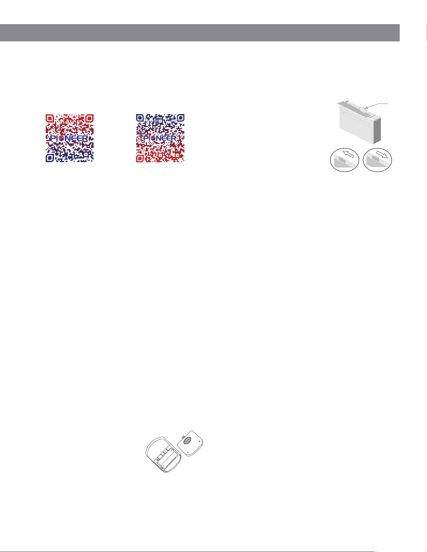
15. Fresh Air System
The unit is equipped with a fresh air intake
feature that allows outdoor air to be introduced
into the room.
Important Notes
• Cooling and heating performance may be
reduced when the fresh air intake is open
• For optimal efficiency, keep the intake
closed during normal operation
• Open the intake periodically to refresh
indoor air as needed
• Open or close the fresh
air inlet using the control
on the top of the unit
• When open, outside air
is drawn into the room
to improve ventilation
16. Maintenance
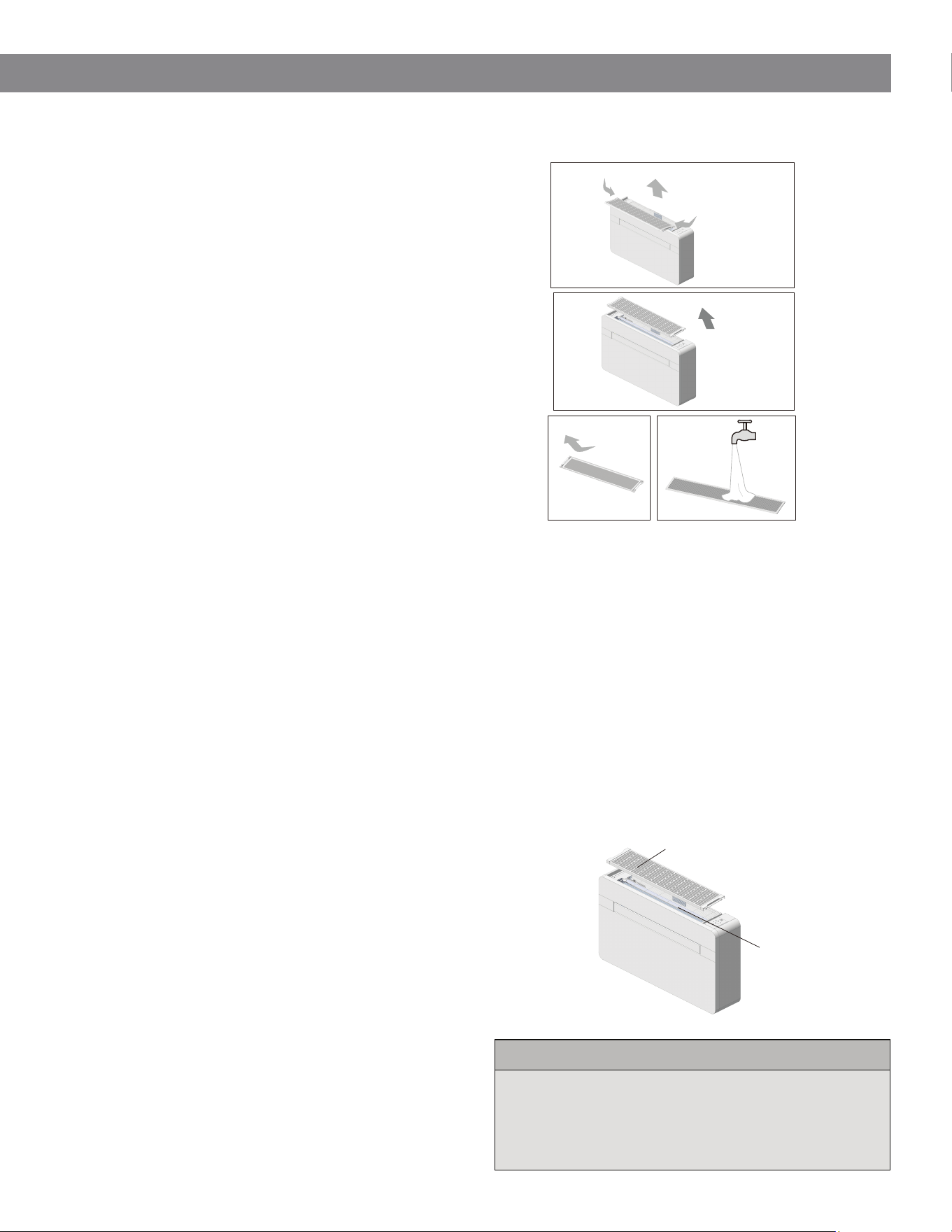
Filter Cleaning (See Page 26 for Illustration)
• Clean the air filters regularly to maintain
performance and air quality.
• Recommended interval: Every 2 weeks (or
as needed based on usage).
Procedure
1. Turn off the unit and disconnect power
2. Remove the air filter(s) as indicated
3. Wash with clean water (avoid hot water)
4. Allow filters to dry completely before
reinstalling
5. Reinstall filters securely in their original
position
Important
▪ Do not operate the unit without filters
installed. This may cause damage and
reduce performance.
External Cleaning
▪ Turn off the unit and disconnect power
▪ Wipe surfaces with a soft, damp cloth
Do Not:
▪ Use abrasive cleaners or solvents
▪ Use excessively wet cloths or allow
water to enter the unit
14. Remote Battery Installation
Check Operation
If the display does not respond after pressing
the ON/OFF button, verify battery installation
and replace if necessary.
1. Open the battery cover
by releasing the latch
and lifting gently
2. Insert two AAA batteries,
ensuring correct polarity
3. Reinstall the battery
cover securely
Download iOS App Download Android App
26
III. Usage and Maintenance
17. Troubleshooting Illustrated Filter Cleaning Steps
If the unit is not operating as expected, please review the
following before contacting service.
Common Issues & Solutions
Unit Does Not Turn On
• Check that power is connected and the circuit
breaker is not tripped
• Verify the ON/OFF button has been pressed
• Confirm timer settings are not preventing operation
Insufficient Cooling or Heating
• Ensure the temperature setting is appropriate
• Clean the air filters if dirty
• Check that air inlets and outlets are not blocked
• Close doors and windows to prevent heat gain/loss
Unit Delays Start-Up
• A delay of up to 3 minutes after restart is normal
• This is a built-in protection feature for the
compressor
Water Leakage
• Ensure the drainage pipe is properly installed and
unobstructed
• Verify the unit is installed level
• Check for excessive humidity in the room
Unusual Odor
• Odors may result from accumulated dust, moisture,
or room contaminants
• Clean the air filters and allow the unit to run in fan
mode
Remote Control Not Working
• Replace batteries if depleted
• Ensure batteries are installed with correct polarity
• Confirm there are no obstructions between the
remote and the unit
Additional Considerations
• High humidity from the environment (walls, carpets,
furnishings) may affect performance
• Improper installation can impact operation and
efficiency
• Blocked airflow or restricted grilles will reduce system
performance
Safety Notice
If the power supply cord is damaged, it must be replaced
by the manufacturer, an authorized service provider, or a
qualified technician to avoid hazard.
Operating Conditions
For optimal performance, operate the unit within the
following conditions:
• Cooling Mode (Maximum):
▪ Outdoor: 115°F DB / 75°F WB
▪ Indoor: 80°F DB / 67°F WB
• Heating Mode (Minimum):
▪ Outdoor: 17°F DB / 15°F WB
▪ Indoor: 70°F DB
Electrical Heater Location
The auxiliary electrical heater (if equipped) is located at
the top of the unit and is protected by the top grille.
When to Contact Support
• Unit does not power on after checks
• Repeated breaker trips
• Persistent water leakage
• Error codes displayed
Electrical Heater
Top Grille
Lift
Here
Lift
Here
P21
P22
P23
P24
26
III. Usage and Maintenance
17. Troubleshooting Illustrated Filter Cleaning Steps
If the unit is not operating as expected, please review the
following before contacting service.
Common Issues & Solutions
Unit Does Not Turn On
• Check that power is connected and the circuit
breaker is not tripped
• Verify the ON/OFF button has been pressed
• Confirm timer settings are not preventing operation
Insufficient Cooling or Heating
• Ensure the temperature setting is appropriate
• Clean the air filters if dirty
• Check that air inlets and outlets are not blocked
• Close doors and windows to prevent heat gain/loss
Unit Delays Start-Up
• A delay of up to 3 minutes after restart is normal
• This is a built-in protection feature for the
compressor
Water Leakage
• Ensure the drainage pipe is properly installed and
unobstructed
• Verify the unit is installed level
• Check for excessive humidity in the room
Unusual Odor
• Odors may result from accumulated dust, moisture,
or room contaminants
• Clean the air filters and allow the unit to run in fan
mode
Remote Control Not Working
• Replace batteries if depleted
• Ensure batteries are installed with correct polarity
• Confirm there are no obstructions between the
remote and the unit
Additional Considerations
• High humidity from the environment (walls, carpets,
furnishings) may affect performance
• Improper installation can impact operation and
efficiency
• Blocked airflow or restricted grilles will reduce system
performance
Safety Notice
If the power supply cord is damaged, it must be replaced
by the manufacturer, an authorized service provider, or a
qualified technician to avoid hazard.
Operating Conditions
For optimal performance, operate the unit within the
following conditions:
• Cooling Mode (Maximum):
▪ Outdoor: 115°F DB / 75°F WB
▪ Indoor: 80°F DB / 67°F WB
• Heating Mode (Minimum):
▪ Outdoor: 17°F DB / 15°F WB
▪ Indoor: 70°F DB
Electrical Heater Location
The auxiliary electrical heater (if equipped) is located at
the top of the unit and is protected by the top grille.
When to Contact Support
• Unit does not power on after checks
• Repeated breaker trips
• Persistent water leakage
• Error codes displayed
Electrical Heater
Top Grille
Lift
Here
Lift
Here
P21
P22
P23
P24
27
III. Usage and Maintenance
18. Error Codes
Indoor Unit Faults
• A1 - Indoor control board (EEPROM) fault
• A2 - Indoor fan malfunction
• A3 - Water temperature sensor fault
• A4 - Indoor coil temperature sensor fault
• A5 - Indoor ambient temperature sensor
fault
Outdoor Unit & System Faults
• A8 - Outdoor control board (EEPROM) fault
• C2 - Outdoor coil temperature sensor fault
• C3 - Outdoor ambient temperature sensor
fault
• C4 - Outdoor fan malfunction
Refrigeration & Valve Faults
• E5 - Four-way reversing valve fault
• E6 - Low refrigerant (charge deficiency)
Compressor & Drive Faults
• b4 - Compressor start failure (phase loss or
reverse phase)
• b5 - Compressor synchronization fault
• b6 - IPM (inverter power module) fault
• b8 - Discharge (exhaust) temperature
sensor fault
Protection & Safety Shutdowns
• FL - Drainage system full (water level
protection activated)
• d1 - Outdoor unit overcurrent protection
• d2 - Compressor phase current protection
• d3 - Supply voltage protection (over/under
voltage)
• d4 - DC bus voltage protection (over/under
voltage)
• d5 - IPM over-temperature protection
• d6 - Discharge temperature overheat
protection
• d7 - Indoor coil anti-freeze protection
(cooling mode)
• d8 / E1 - Outdoor coil overheat protection
Ambient Temperature Protections
• E2 - Cooling mode: outdoor ambient
temperature too low
• E3 - Heating mode: outdoor ambient
temperature too high
Inverter / Electrical Drive Faults
• C5 - DC bus overvoltage protection
• C6 - DC bus undervoltage protection
• C7 - Phase overcurrent fault
• C8 - Abnormal current detection
Important Notes
• Some codes indicate normal protective
behavior, not failure (e.g., voltage or
temperature protections).
• The unit may resume operation
automatically once conditions return to
normal.
• If an error persists after power cycling the
unit, service may be required.
When to Contact Support
Contact a qualified technician if:
• The same error code repeats frequently
• The unit does not resume operation after reset
• Electrical or compressor-related faults are
indicated (b-, C-, or d-series codes)
⚠
Service Required
⏳
Temporary Protection
⚠
⚠
⚠
⏳
⏳
⏳
⚠

The design and specifications of this product are subject to change without prior notice
as development continues. Consult with the sales agency or manufacturer for details.
Refer to the equipment nameplate for all other applicable specifications.
Copyright 2026, Parker Davis HVAC International, LLC., All rights reserved.
is a registered trademark of Parker Davis HVAC International, LLC.
Parker Davis HVAC International
7290 NW 77 Court, Miami, FL 33166 - USA
Tel
: (305) 513-4488
Fax
: (305) 513-4499
E-mail
Website: www.pdhvac.com
Pioneer product line, parts, and supplies are
available online for convenient ordering at:
www.highseer.com
www.pioneerminisplit.com
Scan the below code to visit our support page
where you can find more installation materials: