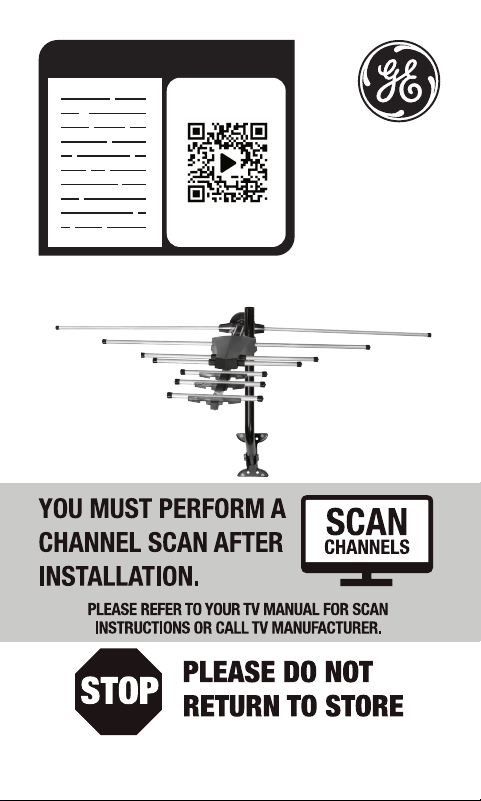
READ IT OR WATCH IT
Read instructions or watch easy-
to-follow video. Scan QR code or
visit https://byjasco.com/33685i
Questions? Contact our U.S.-based Consumer Care
at 1-800-654-8483 between 7AM-8PM CST.

2
WARNING: INSTALLATION OF
THIS PRODUCT NEAR POWER
LINES IS DANGEROUS, FOR
YOUR SAFETY, FOLLOW THE
INSTALLATION DIRECTIONS.
WATCH FOR WIRES! YOU CAN
BE KILLED IF THIS ANTENNA
COMES NEAR ELECTRIC POWER
LINES. READ INSTRUCTIONS!

3
TABLE OF CONTENTS
IMPORTANT SAFETY INSTRUCTIONS ....................................................4
SELECT AND MEASURE YOUR INSTALLATION SITE ......................... 5
CHOOSE A MOUNT TYPE ............................................................................6
ASSEMBLY INSTRUCTIONS - PARTS LIST .............................................7
ASSEMBLY INSTRUCTIONS ........................................................................9
ANTENNA GROUNDING & CONNECTION ........................................ 15
EASY INSTALLATION GUIDES .................................................................19
ANTENNA REMOVAL ................................................................................. 19
ANTENNA HELPFUL TIPS .........................................................................20

4
IMPORTANT SAFETY INSTRUCTIONS:
• NEVER touch ANYTHING or ANYONE in contact with a
power line. You can be electrocuted. In case of an accident
or emergency, call 911 immediately for help.
• INSPECT your installation site carefully for power lines.
Make sure there is no possibility the antenna, its mounting
structure or your ladder can contact power lines. Be sure
to consider what can go wrong during installation.
• KEEP the distance between power lines and the antenna
and its mounting structure at least 2 times the combined
height of the antenna and mounting structure. If the
antenna falls during or after assembly, there must be
sufficient distance to ensure it does not contact the
power lines.
• KEEP your ladder, antenna and its mounting structure
(such as the mast pole and mount) far away from power
lines at all times.
• GROUND the antenna and the antenna mounting
structure in accordance with the NEC electrical
code, all state and local electrical code requirements.
• COMPLETE the antenna assembly on the ground prior to
mounting.
• DO NOT use a metal ladder or install the antenna on a
windy day. If the antenna or mast starts to fall, allow it to
fall. Do not attempt to catch the antenna.
• EXERCISE caution when working on a roof.
• APPLY the included danger label to the base of the
antenna mounting structure.
• INFORM others about the danger of touching power lines
or objects in contact with power lines.
• CONTACT a professional installer in your area to do the
antenna installation if you are unsure how to safely install
and ground this antenna.

5
SELECT AND MEASURE YOUR INSTALLATION SITE
Key things to consider in choosing the antenna installation
site are:
1) Choose a SAFE location far away from power lines. Keep
the distance between power lines and the antenna and
its mounting structure at least 2 times the combined
height of the antenna and its mounting structure. Refer to
the Important Safety Instructions.
2) Determine the location of the broadcast towers in your
area. You need to point the small end of your antenna
toward those towers. There are online resources such as
www.antennaweb.org that can help you identify the
location of your local broadcast towers and the channels
you can expect to receive.
3) Check your local, city and state building and electrical
codes. Make sure your planned installation is safe and in
compliance with all applicable codes, rules and
regulations.
6
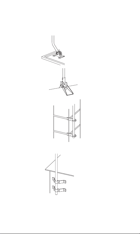
CHOOSE A MOUNT TYPE:
Some examples of common mounting options are shown
below. Follow the installation instructions for the mount you
will use:
1) J-Mount
(Provided)
2) Ridge Mount
(Not provided)
3) Chimney Mount
(Not provided)
4) Wall Mount
(Not provided)
IF YOU ARE UNSURE OR DO NOT FEEL CAPABLE
OF INSTALLING THIS ANTENNA, CONTACT
A PROFESSIONAL INSTALLER IN YOUR AREA.
7
ASSEMBLY INSTRUCTIONS:
Thank you for purchasing the Outdoor HD Antenna. This
antenna is a sturdy, high-performance antenna designed
to receive UHF and VHF broadcasted signals. The small,
compact design allows you to install the antenna almost
anywhere on the outside of your house.
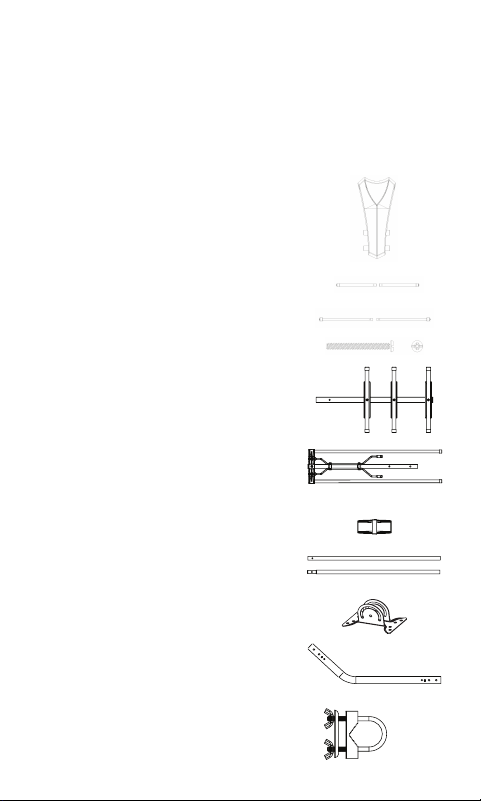
PARTS LIST:
1) Main Housing Unit – 1 ea.
2) Short UHF Elements – 2 ea.
3) Middle UHF Elements – 2 ea.
4) M3 x 25mm Bolts – 4 ea.
(pre-attached to the Main Housing Unit)
5) Main Boom 1 with Short Dipoles – 1 ea.
6) Main Boom 2 with VHF Elements – 1 ea.
7) Main Boom Connector Piece – 1 ea.
(pre-attached to the Main Boom 2)
8) UHF Elements (32.5cm) – 2 ea.
9) Mounting Bracket – 1 ea.
10) J-Mount (15/16 in or 2.5cm) – 1 ea.
11) U-Bolt and Clamp Assembly – 1 ea.
a) Brass plate – 1 ea.
b) Wing Nuts (#10 X 24) – 2 ea.
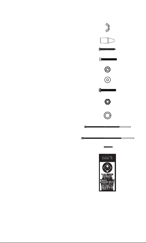
8
PARTS LIST (CONT.):
12) Wing Nuts (#6 X 32) – 4 ea.
(pre-attached to the Main Housing Unit)
13) Rubber Boot – 1 ea.
14) 1/4 X 2 in Lag Screws – 4 ea.
15) M6 X 50mm Bolts – 2 ea.
16) M6 Locking Nuts – 2 ea.
17) M6 Washers – 4 ea.
18) M5 X 40mm Bolt – 1 ea.
19) M5 Nut – 1 ea.
20) M4 Lock Washers – 2 ea.
(pre-attached to the Main Housing Unit)
21) Small Zip Tie – 1 ea.
22) Large Zip Tie – 2 ea.
23) M3 X 16mm Self-Tapping Screw – 1 ea.
24) Danger Label – 1 ea.
9
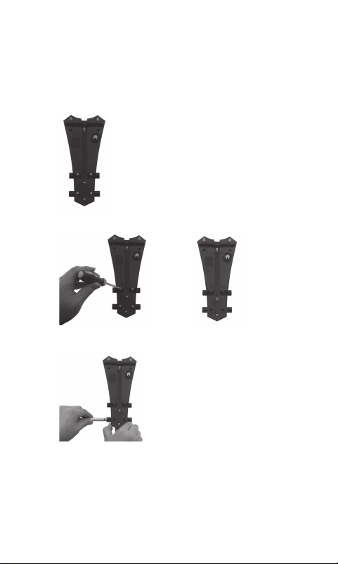
ASSEMBLING THE ANTENNA:
1) Connecting the UHF Elements
a) Turn the Main Housing Unit with the bottom side
facing up. (Fig. 1a)
Fig. 1a
b) Remove the four M3 x 25mm Bolts from the Main
Housing Unit. (Fig. 1b) & (Fig. 1c)
(Fig. 1b) (Fig. 1c)
c) Slide one of the Short UHF Elements into the Main
Housing Unit from the left side. (Fig. 1d)
(Fig. 1d)
d) Align the holes of the Short UHF Element with the
holes of the Main Housing Unit, then secure with the
M3 x 25mm bolts. (Fig. 1e)

10
(Fig. 1e)
e) Slide the other Short UHF Element into the Main
Housing Unit from the right side, and secure with the
M3 x 25mm bolts. The assembly steps are same.
2) Connecting the Middle UHF Elements. The
assembly steps are same as connecting the Short
UHF Elements.
3) Connecting the UHF Elements
a) Turn the Main Housing Unit with the bottom side
facing up. (Fig. 3a)
(Fig. 3a)
b) Slide one of the UHF Elements into the Main Housing
Unit from the left side. (Fig. 3a)
c) Slide the other UHF Element into the Main Housing
Unit from the right side into the first UHF Element.
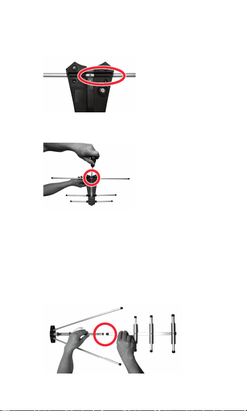
11
(Fig. 3b) Align the holes of the UHF Elements with the
embossed black markings in the center of the Main
Housing Unit.
(Fig. 3b)
d) Secure with the M3 x 16mm Self-Tapping Screw.
(Fig. 3c)
(Fig. 3c)
4) Main Boom Assembly
a) Take the Main Boom 1, turn it with the short
dipoles facing up.
b) Take the Main Boom 2, turn it with the VHF
connector rods marked L and R facing up, and slide
the Main Boom 2 onto the Main Boom Connector Piece
pre-attached to the Main Boom 1. (Fig. 4)
(Fig. 4)
12
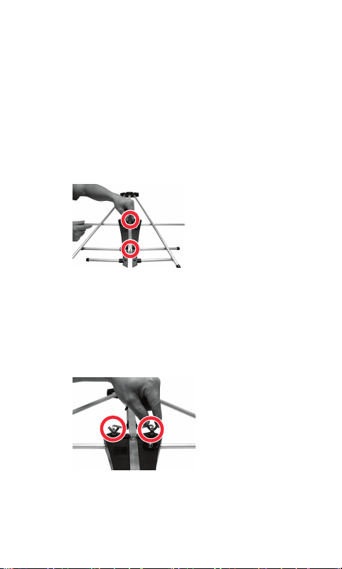
5) Attaching the Main Boom To The Main Housing Unit
a) Position the Main Housing Unit with the bottom side
facing up. Remove the four #6 X 32 Wing Nuts and
the two M4 Lock Washers.
b) Lay the assembled Main Boom into the Main Housing
Unit. (The Main Boom with the short dipoles is
positioned at the narrow end of the Main Housing Unit)
i. Secure the Main Boom assembly to the Main
Housing Unit using two #6 X 32 Wing Nuts just
removed. (Fig. 5a)
(Fig. 5a)
ii. Slide the two VHF connector rods marked L and
R over the two bolts on the Main Housing Unit,
then slide the M4 Lock Washers onto the bolts and
secure with the #6 X 32 Wing Nuts. (Fig. 5b)
(Fig. 5b)
iii. Unfold the two VHF element rods and snap into the
bracket. (Fig. 5c)
13
(Fig. 5c)
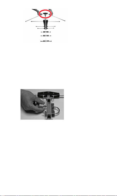
6) Attach the Mast Clamp to the Main Boom
a) Remove the two #10 X 24 Wing Nuts from the U-Bolt
and Clamp Assembly.
b) Attach the Brass Plate provided with the “U” Bolt and
Clamp Assembly to the Antenna Main Boom. (Fig. 6)
c) Slide the U-Bolt into the holes on the Antenna Main Boom
from the opposite side of the Brass Plate. (Fig. 6)
(Fig. 6)
e) Thread the Wing Nuts partially back onto the U-Bolt. (Fig. 6)
7) Installing the Assembled Antenna
a) Locate a position on the house that is far away from
power lines. Refer to the Important Safety Instructions.
b) Secure the Mounting Bracket to the location selected
for the antenna. The 1/4 X 2” Lag Screws have been
provided for some installations.
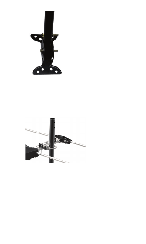
c) Connect the J-mount to the Mounting Bracket
(Fig. 5a) using the M6 X 50mm Bolts, M6 Locking Nuts
and M6 Washers.
14
(Fig. 7a)
d) Position the J-Mount perpendicular to the ground
using a small level.
e) Slide the Antenna onto the J-Mount. (Fig. 7b) Point
the small end of the antenna in the direction of
the broadcast towers in your area. Tighten
the Wing Nuts on the U-Bolt when the antenna is in
the desired position.
(Fig. 7b)
15
Antenna Grounding & Connection
The National Electric Code (NEC) requires your outdoor
antenna installation to be properly grounded. This involves
grounding both the antenna and the antenna mounting
structure. This helps protect you and your property in the
event of static build up on the antenna or lightning near your
home.
Note: If you had a satellite or cable system installed at your
home, you may be able to use some of the parts from this
system for your antenna installation.
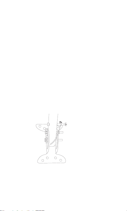
a) Ground the Antenna Mount: Attach an 8 AWG
aluminum or 10AWG copper grounding wire to the
antenna mounting structure, for example pole, mast,
tower, etc. In some cases, a bolt on the mount can be
used for making this connection. When using the J-
Mount provided, use the M5 Bolt and M5 Nut in
the hole on the J-Mount located above the
Mounting Bracket to make this connection. (Fig. 8a)
(Fig. 8a)
Tighten this connection securely. Ensure there is a
good electrical connection between your mounting
structure and grounding wire. Run the grounding wire
as straight as possible and use standoff insulators
spaced four (4) to six (6) feet apart. Attach the
grounding wire to an acceptable building ground
location.
16
Examples of acceptable building grounding
locations are:
• The building or structure grounding electrode
system as covered in 250.50 in the NEC.
• Grounded interior metal water piping system, within
5ft. from its point of entrance to the building.
• Grounded nonflexible metallic power service
raceway.
• Service equipment enclosure, the grounding
electrode conductor or the grounding electrode
conductor metal enclosure of the power service.
• An 8ft. grounding rod driven into the ground
can be used as long as it is connected to the central
building ground by a 6AWG or heavier bonding wire.
Refer to the NEC sections 250 and 810 for other
acceptable grounding methods.
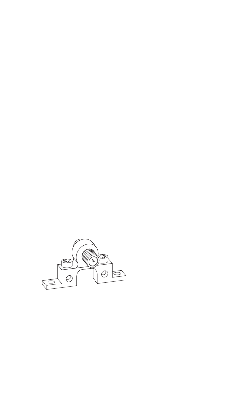
b) Antenna Connection: Connect one end of a coax
cable to the antenna and the other end to a 75 ohm
grounding block. Below (Fig. 8b) is an example of a 75
ohm grounding block.
(Fig. 8b)
If you make your own coax cable, slide the
Rubber Boot over the cable before you place the
connectors on the cable. Once you have attached the
cable to the antenna, slide the Rubber Boot into the
round channel on the Main Housing Unit.
17
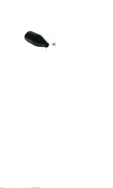
If you are using a pre-built cable that has connectors,
follow these steps.
i. Cut 4 slits spaced evenly apart at the narrow tip of the
provided Rubber Boot approximately 1/4in. in length.
(Fig. 8c)
(Fig. 8c)
ii. Run the coax cable through the narrow end of
the Rubber Boot and attach the cable to the
antenna.
iii. Slide the Rubber Boot into the round channel on
the Main Housing Unit.
iv. Using the Small Zip Tie, wrap the tie around the
narrow tip of the Rubber Boot around the four
slits and pull the tie tight.
Use a second coax cable and connect one end to the
mating port of the first coax cable on the 75 ohm
grounding block and run the other end into your home
for connecting to your TV. The 75 ohm grounding block
needs to be placed as close as possible to the point
where the second coax cable enters your home.
Note: Leave enough slack in the coax cable to create a
drip loop so moisture cannot enter the house. You
will also need to seal the coax cable entry point into
your house with an exterior caulk.
c) Ground the 75 ohm Grounding Block: Connect
an 8AWG aluminum or 10AWG grounding wire to
a screw terminal provided on the 75 ohm grounding
block. Connect the other end of the wire to an
acceptable building ground location.
Refer to step a) in this section for acceptable building
grounding locations.
18
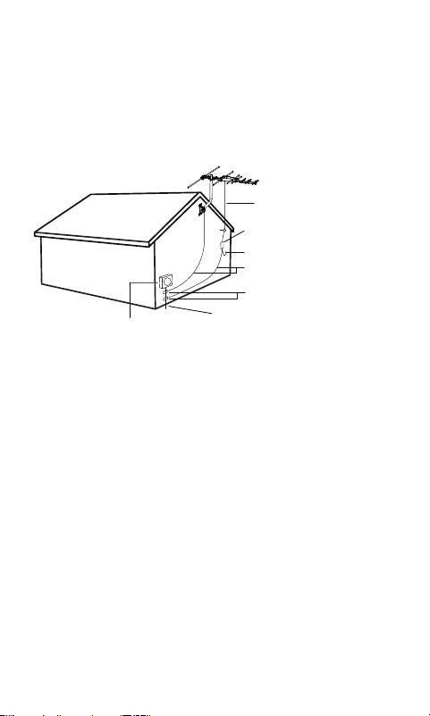
Double check all your connections after installation
is complete. Ensure there are good electrical
connections of your grounding wires and
coax cables. See Fig. 6d below for an example of a
properly grounded antenna installation.
Example of Antenna Grounding
as per NEC - National Electrical Code
ELECTIC SERVICE METER PANEL
POWER SERVICE GROUNDING ELECTRODE SYSTEM
(NEC ART 250. PART H)
GROUNDING CONDUCTORS
(NEC SECTION 810-21 )
GROUND CLAMPS
75 OHM GROUNDING BLOCK
(NEC SECTION 810-20)
ANTENNA COAX
RAIN DRIP LOOP FOR THE COAX TO TV
(Fig. 8d)
If you are unsure how to properly ground your antenna
installation, contact a professional installer in your area.
d) Danger Label Application: If your antenna mounting
structure, such as a mast, J-Mount or pole, does not
have a danger label, apply the label provided
to the base of the mounting structure in a clearly
visible location.

19
EASY INSTALLATION FOR HDTVs
1) Connect the coax cable from the antenna to the antenna
input on your HDTV.
2) Follow your HDTV’s instruction manual to scan for
channels on your television.
EASY INSTALLATION FOR ANALOG TVS WITH SET-TOP BOX
1) Connect the coax cable from the antenna to your set-top
box antenna input. Then, connect another coax cable
(not included) to the antenna output on the set-top box.
2) Connect the other end of that cable to the antenna input
on your TV.
3) Follow your set-top box instruction manual to scan for
channels on your set-top box.
ANTENNA REMOVAL
Inspect the area carefully for power lines. Look for any new
power lines that may have been installed. Make sure there
is no possibility the antenna, its mounting structure or your
ladder can come in contact with power lines. Be sure to
consider what can go wrong during the antenna removal.
Repeat the steps for antenna installation but in reverse order.

33685 V7
08/21/2020
MADE IN CHINA
GE is a trademark of General Electric Company and is under
license by Jasco Products Company LLC, 10 E. Memorial Rd.,
Oklahoma City, OK 73114.
This Jasco product comes with a limited-lifetime warranty.
Visit www.byjasco.com for warranty details.
Questions? Contact our U.S.-based Consumer Care at
1-800-654-8483 between 7AM—8PM CST.
ANTENNA HELPFUL TIPS
Maximize the number of channels you receive by aiming the
antenna in different directions to see which position provides
the best reception and the maximum number of channels. Be
sure to run a new channel scan for each position. Refer to the
instruction manual that came with your TV if you are not sure
how to do this.
Visit www.antennaweb.org or www.dtv.gov and look for the
DTV Reception Maps to determine the available television
stations and location of the broadcast towers in your area.
FOR FURTHER ASSISTANCE, CALL 1-800-654-8483 FOR
TECHNICAL SUPPORT.