1
American Dish Service
INSTALLATION INSTRUCTIONS
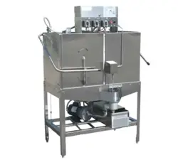
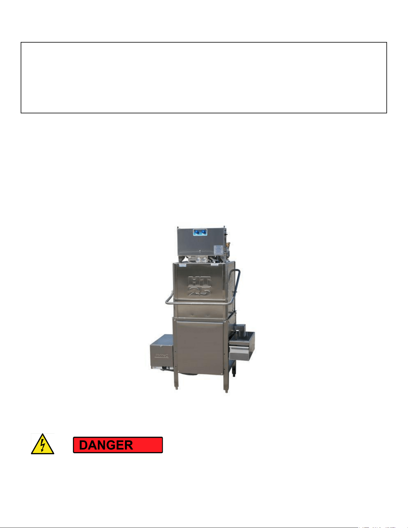
Model HT-25
208v/240v, 3-phase, 40a/4-Wire
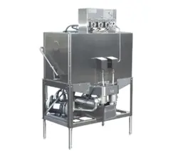
High Temp Dishmachine w/Built-on Booster Combo 208v/240v, 3-ph, 50a
Listed by UL #E68594, NSF/ANSI 3, ASSE 1004 #933, LA Test Labs File M-780089, Mass. License P3-0111-306
If you have questions, call 800-922-2178 or visit our website at www.AmericanDish.com
The electrical power supplied to this machine is an imminent hazard that could result in severe bodily injury
or death if not properly installed or hooked up correctly. When working in the control box or on electrical
Copyright ADS Installation Manual Model HT-25 (4 wire), Revision 3.1, 6/14/2017

2
parts, always disconnect power and tag-out before servicing. Replace cover to control box and other
protective covers when finished servicing this equipment.
READ Manufacturer’s Manual before Using this Product. For your safety read and observe all cautions
shown throughout these instructions. While performing installations described in this booklet, wear
approved Personal Protective Equipment, including Safety Eye-Wear.
There are potentially hazardous situations when working with industrial cleaning chemicals for
dishmachines. See chemical manufacturer’s MSDS sheets and safe practices for handling and installing
chemical feeders and supply containers.
WARNING: Cancer and Reproductive Harm – www.P65Warnings.ca.gov
#1 Before you begin: American Dish Service provides this information as a service to our customers. Keep all
instructions for future reference. ADS reserves the right to alter or update this information at any time.
Should you desire to make sure that you have the most up-to-date information, we would direct you to the
appropriate document on our web site: www.americandish.com. Set out below are the specifications and
requirements that you must use and follow to properly install the type or types of equipment listed above.
It is your obligation as the customer to ensure that the machine is installed safely and properly, and when
completed, the machine is left in proper and safe working order. Electrical, Plumbing, and Chemical hookup
should be performed by a qualified professional who will ensure that the equipment is installed in
accordance with all applicable Codes, Ordinances, and Safety requirements. Failure to follow the
installation instructions could void the warranty. ADS assumes no liability or control over the installation of
the equipment. Product failure due to improper installation is not covered under the ADS Warranty.
#2 This equipment is considered a heavy use item. It is not rated for outdoor use.
#3 Do not install spray arms until machine is flushed with water. When this machine is connected to power,
it will normally fill with water and complete one cycle. Do this without the spray arms. Dump that water
out before installing spray arms. Draining the water will flush installation debris from the tank and pump;
this prevents damage to spray arm bearings. To drain, pull the pump filter out of the sump.
#4 Important—Dishmachines must be installed to allow for servicing of motor and plumbing. Do not install
chemical dispensers on the top of the control box or machine.
Copyright ADS Installation Manual Model HT-25 (4 wire), Revision 3.1, 6/14/2017
3
#5 WATER HEATERS or boilers must provide the minimum temperature of 120F degrees required by the
machine listed above, which has a minimum demand of 61.2 gallons per hour. These specifications are for
the dishmachine only, which typically accounts for 70% of a restaurant’s hot water demand.
For HOT WATER SANITIZING, an additional booster heater must be installed to reach 180F minimum for the
final rinse. This booster will require a rise of 70-degrees. (The HT-25 does not have an internal booster
heater, but ADS offers a combo package with a booster built-on to the left side of the machine and wired for
a single point electrical connection. The combo option is only available in 3-phase electrical power.)
#6 INSPECT FOR DAMAGE—If you receive a damaged dishmachine, do not sign “Clear” but write
“Damaged” on the documents.
ELECTRICAL SECTION
The electrical power supplied to this machine is an imminent hazard that could result in severe bodily
injury or death if not properly installed or hooked up correctly.
#1 Before powering up the machine, CHECK ALL ELECTRICAL SCREW TERMINALS in the control box on top of
the machine and the heater box. Screws can loosen in transit. Loose connections on high amp load
terminals will cause wire burning and component damage during operation and will not be covered under
ADS warranty. The term “Clean Circuit” means the electrical circuit breaker supplies no other devices,
motors, machines, or lights.
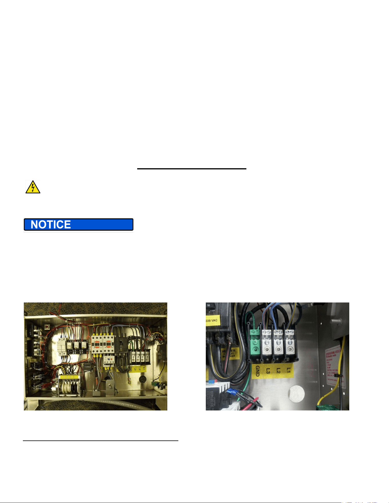
Showing HT-25, 4-wire control box Main distribution block for incoming wire & 1” conduit hole
Electrical HT-25 with Built-on Booster (3-phase, 50a/4-Wire)
Copyright ADS Installation Manual Model HT-25 (4 wire), Revision 3.1, 6/14/2017
4
ORDERING INSTRUCTIONS—Machines with heaters are voltage specific, order according to actual voltage at
the installation (see kW chart in the Appendix)
IT IS RECOMMENDED THAT THIS EQUIPMENT BE INSTALLED USING A NEW CIRCUIT BREAKER. No
neutral wire is required for this model. The power supply of 208 volts, 3-phase, 50-amps must consist of three
8-gauge wires and one suitable green ground wire. This is called a 4-wire connection. This is a single electrical
connection point for both dishmachine and the attached booster combination when purchased from the
factory. The 50-amp breaker or fuses must be on a clean circuit to the machine. ADS has provided a 1”conduit
hole (1 3/8”actual size) for electrical service in the back of the control box. Attach 8-gauge wires to terminals
marked L1, L2, & L3 on the main distribution block in the control box. Attach a green ground wire from the
building to the location marked GND on the main distribution block and tighten all wires. There is no control
circuit transformer. This control circuit is 230v and will require 230v coils, relays, solenoids, and lights for all
repairs. THIS MODEL IS ALSO AVAILABLE WITHOUT A BOOSTER AT 40 AMPS.
FOR 240 VOLT OR DELTA SYSTEMS— attach the high leg (200 volt line) to L3. Attach your 120 volt lines to L1
and L2. If power is 240v, see kW rating chart at the back of the manual for correct heater sizing and available
ADS heater elements.
3-Phase MOTOR ROTATION—Remove front panels and check rotation of motors. A rotational arrow is placed
on the wash pump motor. If this motor is running in reverse of the arrow, turn off main power and switch the
incoming power wires on L1 & L2. Verify proper rotation and tighten all wires.
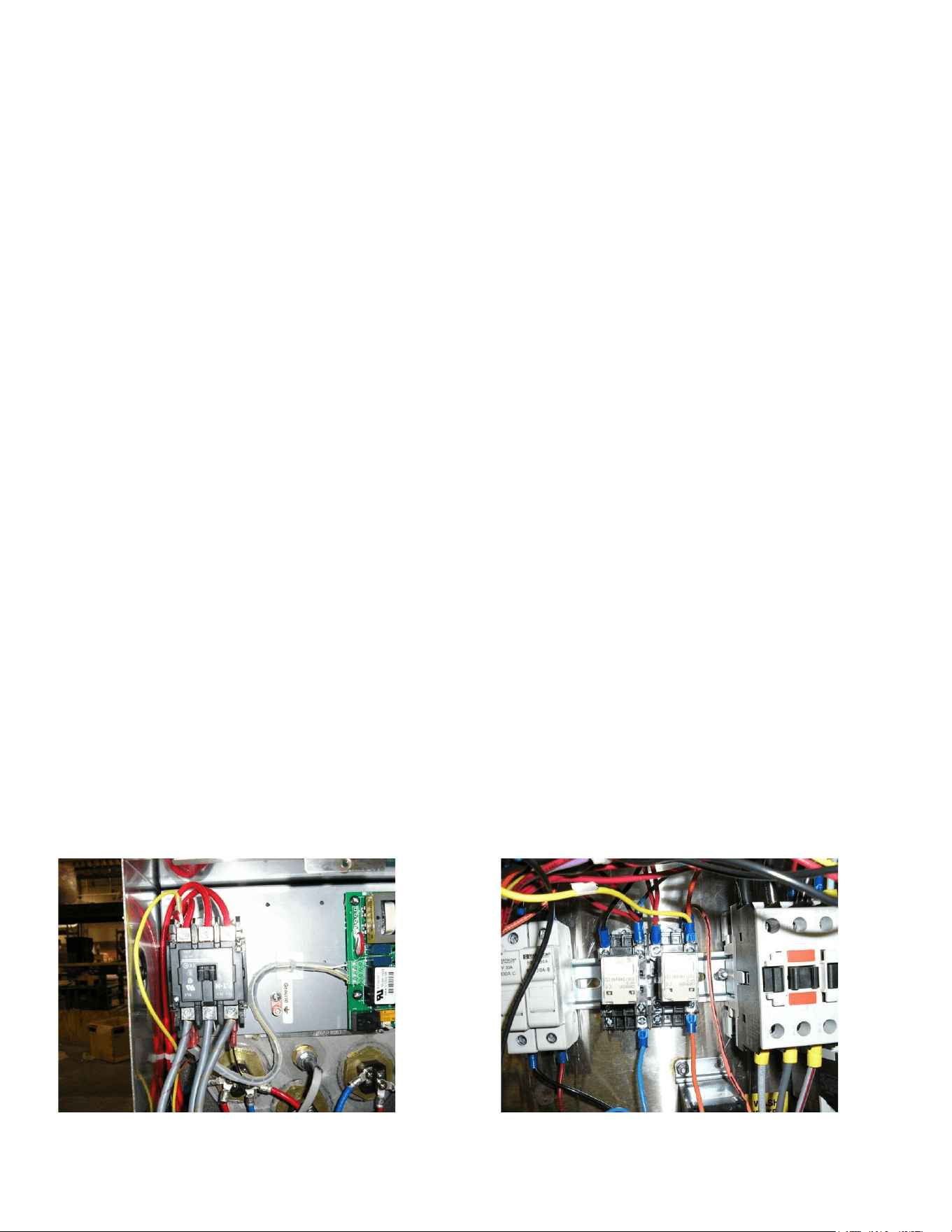
BUILT-ON BOOSTER COMBO ELECTRICAL—The combo package uses an inter-latch circuit to turn off the
dishmachine sustainer heater anytime the booster turns on. In this feature, there is only one heater circuit
energized at a time— allowing both booster and dishmachine to be installed on one 50a service. Connections
in the booster heater come from the HT-25 control box. The gray 3-phase power wires come from the 50a
breaker in the HT-25 control box and connect to the incoming side of the booster contactor. The single yellow
wire connects to the heater side of the contactor on the L1 terminal. The yellow wire connects in the HT-25
box to the relay controlling the dishmachine sustainer heater. The dishmachine and booster combination
come pre-wired from the factory.
Showing booster contactor, yellow signal wire Yellow signal wire from the booster controls heater relay
Copyright ADS Installation Manual Model HT-25 (4 wire), Revision 3.1, 6/14/2017

5
EXCEPTION—HT-25 4-Wire with booster is NOT AVAILABLE in single-phase
PLUMBING SECTION
#1 TANKLESS WATER HEATERS can be problematic for commercial dishmachines. The ADS model HT-25
dishmachine require heated water 61.2 gallons per hour at 20 psi as measured at the final rinse manifold,
with a minimum temperature of 120F. It has been the experience of ADS that tankless supply systems
require multiple units plumbed in sequence with a recirculation loop to achieve proper pressure and
temperature.
Check with the tankless water heater manufacturer, they may recommend a storage tank to guarantee
proper flow and line pressure to the machine. Failure to provide adequate water quantity, pressure and
temperature to the machine will cause the machine to function improperly and is not the responsibility of
ADS. Improperly installing ADS equipment in this manner could void the warranty. All costs associated with
providing an adequate water supply to the machine is the sole responsibility of the user.
#2 DRAIN SIZE—Gravity drain lines are 2” pipe size. Do not use reducing adapters for drain lines, always use
same diameter pipe or larger. Close pump petcocks if equipped.
#3 A PRESSURE REDUCING valve with by-pass should be installed before the booster heater if the line
pressure is 50 psi or above. This is according to booster manufacturer’s instructions.
#4 BURN HAZARD from hot water from pumped sprays or plumbing leaks.
#5 ELECTRICAL SHOCK HAZARD on bare electrical terminals in the thermostat box or control box.
#6 HOODS—Follow all local plumbing and mechanical codes. IMC 2012, section 507.2.2 requires Type II
hoods for all commercial dishwashers except where the heat and moisture loads are incorporated into the
building’s HVAC systems or dishwashing equipment designed with separate heat and moisture removal
systems. A door-type, single-rack, hot-water sanitizing dishwasher is rated at 4770 Btu/h by table 5E,
ASHRAE Research Project #1362, 8/5/2008. ADS DOES NOT SPECIFY BUILDING HVAC VALUES
Copyright ADS Installation Manual Model HT-25 (4 wire), Revision 3.1, 6/14/2017
6
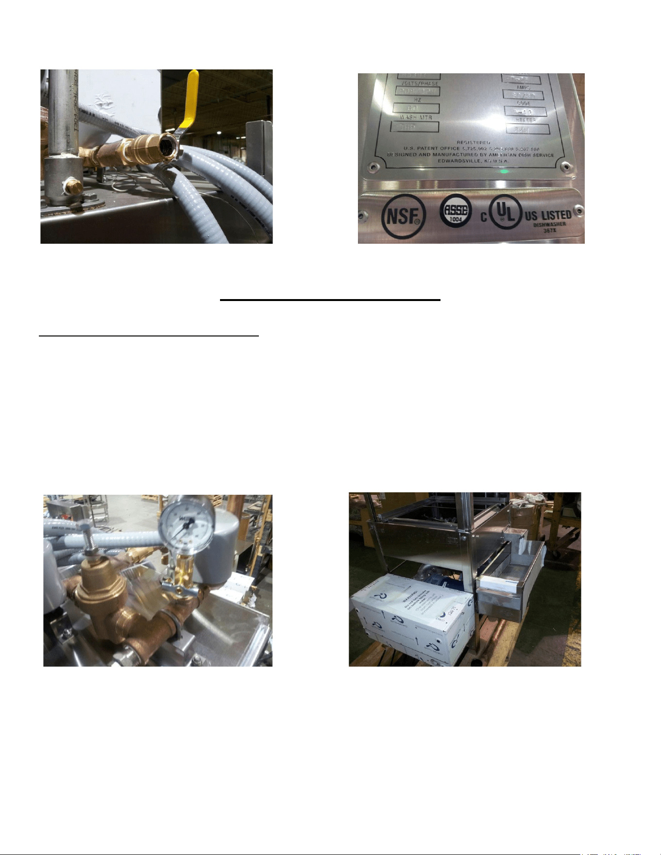
Showing final rinse mixing chamber, hot-water inlet to HT-25 Data plate information and listing marks
DUAL SANITIZING MODE
Hot Water Sanitizer Connection
Flush the building’s water lines before connecting to the dishmachine to avoid fouling the inlet water solenoid.
For high temp sanitizing this inlet water line must come from a stand-alone booster heater or the ADS HT25
w/built on booster. Connect ¾” MPT water supply line to the booster for the combo or a ½” MPT to the top of
the dishmachine inlet manifold when using a stand-alone booster. The requirement at the dishmachine is 180
F minimum at 20 PSI during final rinse, with a demand of 61.2 GPH. The pressure is measured at the pressure
gauge mounted next to the pressure reducing valve in the inlet plumbing on top of the machine’s hood. To
adjust pressure, turn adjustment screw atop the valve counter-clockwise to decrease pressure.
Showing pressure reducing valve for final rinse & gauge* Showing built-on booster mounted in corner position (front)
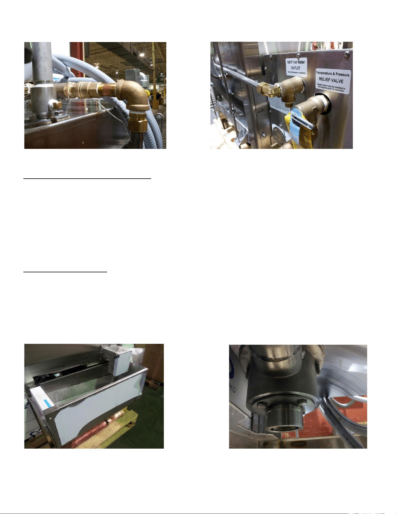
BUILT-ON BOOSTER COMBO PLUMBING—Incoming hot water attaches to the lower ¾”inlet on the booster
heater. This should come from the building’s hot water heater. The dishmachine and booster come
pre-plumbed from the factory and pre-wired. The only connection is the incoming hot water to the booster. A
pressure reducing valve with by-pass should be installed before the booster heater if the line pressure is 50 psi
or above.
Copyright ADS Installation Manual Model HT-25 (4 wire), Revision 3.1, 6/14/2017
7
HT hot water inlet ball valve, connected to booster line Booster hot outlet line going up to HT-25 inlet manifold
Chemical Sanitizer Connection
For chemical sanitizing the hot water line will come directly from the building’s water heater. Connect ½” MPT
water supply line to the inlet manifold. The requirement at the dishmachine is 120 F minimum at 20 PSI during
final rinse, with a demand of 61.2 GPH. The pressure is measured at the pressure gauge mounted next to the
pressure reducing valve in the inlet plumbing on top of the machine’s hood. To adjust pressure, turn
adjustment screw atop the valve counter-clockwise to decrease pressure. A chemical dispenser must be added
that has a third pump for chlorine.
Drain Requirements
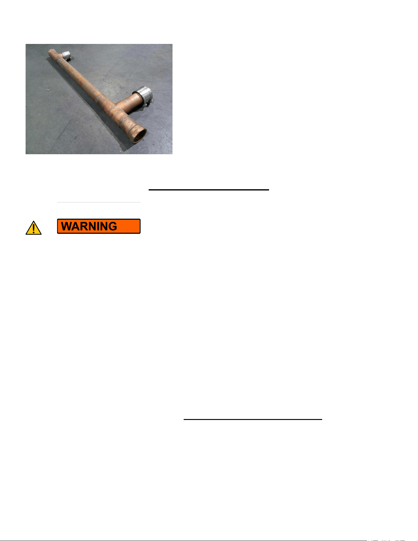
ADS provides a 2” copper drain manifold for the tank and scrap box, the manifold is shipped strapped to the
pallet of the dishmachine. After installation, attach the drain manifold using the rubber “no-hubs” on the
manifold. To prevent clogging, run drain lines as straight as possible. Do not plumb with tight radius elbows or
180-degree bends. Use of floor sinks for drains can cause flooding. Do not use reducing adapters for drain
lines, always use 2” diameter pipe or larger. Always run gravity drain lines downhill.
Scrap box and 2”drain manifold attached to pallet for shipping Drain sump connection for copper drain, bottom of tank
Copyright ADS Installation Manual Model HT-25 (4 wire), Revision 3.1, 6/14/2017
8
HT-25 drain manifold with “no-hub” connectors
DISPENSER HOOK-UP
You must wear approved safety eye-wear before connecting chemicals equipment. Commercial cleaning
chemicals are highly concentrated, they can cause damage to mechanical and electrical parts of the
dishmachine. Do not mount dispensers on top of the control box or run chemical lines over controls or
plumbing. Always secure chemical lines and check regularly for leaks. If not properly handled, chemicals
can cause serious bodily injury. In the event of chemical contact to skin or eyes; wash immediately with
fresh water and seek medical attention.
CONTAINERS: When a chemical delivery system is connected to the ADS high temp dishmachine using
5-gallon pails for industrial ware-washing chemical products, these must be equipped with Closed Loop
containers. Always use chemical resistant safety gloves and safety goggles (indirect- vented or non-vented)
when changing chemical buckets. Immediately report spills and refer to your chemical suppliers SDS safety
data sheet or MSDS material safety data sheet for information if chemical come in contact with skin or eyes.
Any modifications to the chemical delivery system for smaller containers must include Closed Loop Chemical
Containers (spill proof bottles) in a secured racking system. It is the responsibility of the user of the machine
to purchase chemicals in spill proof containers. FAILURE CAN RESULT IN SERIOUS INJURY. Never place
chemicals in open containers or containers that can be easily tipped over when moving or changing product.
Failure to do so is a safety hazard and will also void the ADS warranty.
There is NO CHEMICAL DISPENSER included with this model. Chemical dispensers must be provided and
installed prior to operation. The installation of the dispenser is typically provided by the chemical supplier.
DE-LIME SWITCH
Copyright ADS Installation Manual Model HT-25 (4 wire), Revision 3.1, 6/14/2017
9
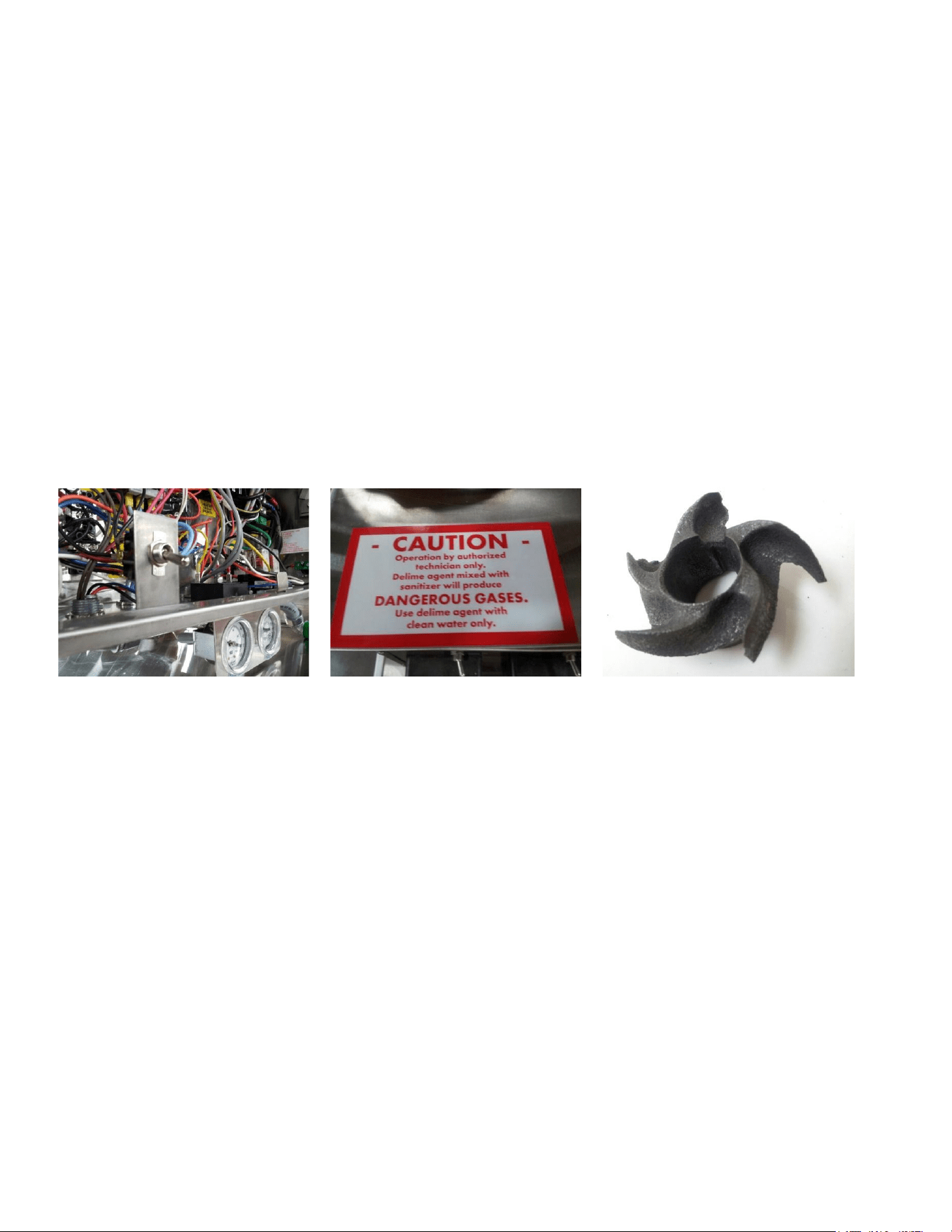
The de-lime switch is placed inside of the control box to avoid unauthorized operations. Because of
potentially hazardous gas resulting from the combination of chlorine with acid solution, only authorized
trained individuals should be allowed to de-lime a commercial dishmachine.
INSTRUCTIONS FOR USING THE DE-LIME FEATURE ON A HT-25 are first turn off the machine then empty all
water out of the machine by removing the pump filter/drain plug. After all water has emptied out, replace the
pump filter/drain plug and fill the machine with fresh water by turning on the master switch. After the tank is
filled and fill water has shut off, add the de-lime acid to the tank water. Turn on the de-lime switch to operate
the pump motor. READ THE DIRECTIONS ON THE CONTAINER FOR CORRECT CONCENTRATION OF THE
CHEMICAL. TYPICAL CONCENTRATION LEVELS 1:20 to 1:60.
Let the machine run long enough to return the inside of the machine to the appearance of shinny metal
surfaces. Then empty and refill the tank with fresh water. It is best to de-lime more often with milder acid
solutions than waiting until there is heavy build up of white minerals, then trying to remove the build up with
very strong acid concentrations. Using too strong of an acid solution or running it for very long periods of time
will erode the metal of the impeller because it is spinning in the acid solution. If the final rinse arms are
clogged with mineral deposits, remove from the machine and soak them in a pan with lime remover.
De-lime switch in HT25 control box Warning decal about mixing chemicals Impeller damaged from high acid solution
Copyright ADS Installation Manual Model HT-25 (4 wire), Revision 3.1, 6/14/2017
10
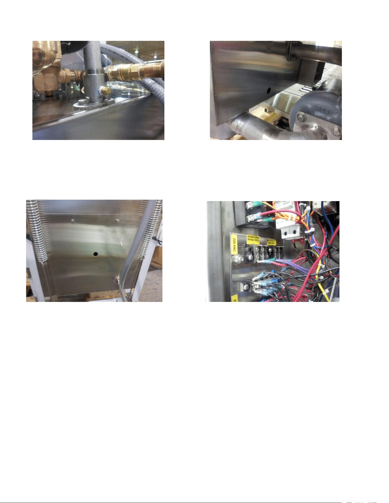
Mixing chamber with two 1/8” pipe threaded port Showing 7/8” detergent probe hole behind pump motor
ADS provides two (2) ports, 1/8” IPS female threads in the final rinse mixing chamber for dispenser check
valves. Probe hole (7/8”) is provided in the wash tank for probe installations (install probe before operating
the machine). Detergent hole (7/8”) is provided for bulk-head fitting (install fitting before operating machine).
Showing back of tank, 7/8” detergent bulkhead fitting hole Showing dispenser signal connection terminals
NOTE: Before turning on the water, if the chemical dispenser has not been installed, plug the probe and
chemical delivery holes in the wash tank and plug the mixing chamber injection ports.
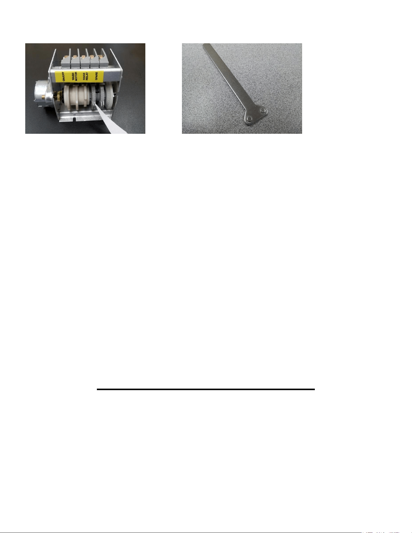
HT-25, 4-wire provides 230v dispenser signals. Connect to chemical dispenser terminal blocks located on the
left-hand side of the control box, look for yellow decal labeled detergent and rinse. The dispenser wash signal
comes from the 4
th
cam on the cam timer. This cam can be adjusted so a signal for detergent can be set for a
certain time or limit during the cycle. The rinse signal comes from the 3
rd
cam, it lasts for 10 seconds and is not
adjustable. The 5
th
cam is a spare for future features.
Copyright ADS Installation Manual Model HT-25 (4 wire), Revision 3.1, 6/14/2017
11
Showing HT-25 cam timer, arrow points to deter cam Cam adjusting tool
TESTING FOR TEMPERATURE—For high temp sanitizing, the measurement is taken at the manifold for a
minimum of 180F, NOT in or at the sprays. If tapes are used to verify temperature, then only 165F labels
should be used, this is the temperature required on the surface of the plates--NOT 180F. This is according to
the NSF/ANSI Standard 3 test protocol.
TYPE OF CHEMICALS—Use only commercial grade low-energy chemicals. For proper operation, use
non-foaming detergents and buffered sanitizers. Do not wash gold, pewter, silver, or silver-plate with chlorine
based sanitizers. High concentrations of chlorine sanitizers and caustic detergents will cause damage to metals
and welds. Do not exceed 50 parts-per-million (PPM) “free” or available chlorine, using higher than 50 ppm will
be dependent on local health requirements, however, the increased chlorine will result in higher corrosion of
metal parts. The resulting damage from overusing chlorine is not covered under the ADS warranty.
Purpose-built ware-washing dispensers are needed to properly meter chemicals for wash and rinse. These
dispensers are not included with this model but must be provided by the company that provides the
ware-washing chemicals. Manually adding industrial chemicals to the dishmachine is unsafe and not
approved.
HARD WATER—Water softeners should be used to correct hard water conditions. Treating hard water
conditions with acid solutions in the machine is discouraged. Hard water is often treated with more expensive
dishmachine chemicals, but it is more effective and less destructive to the metal when the water is softened
before it is used by the dishmachine.
CHECK LIST PRIOR TO INITIAL START UP
Open doors and remove all packaging, including cardboard supports found under the wash tank heater. Do
not dispose of packing material until you remove spray arms. Packing materials contain the installation
manual, QC check sheets; upper and lower wash and rinse arms. Prior to connecting the main power supply,
tighten all wire connections looking for those that loosened during shipping or moving. Before turning on the
water, if the chemical dispenser has not been installed, plug the probe and chemical delivery holes in the wash
tank and plug the mixing chamber injection ports. Turn on the water supply. Check and correct any leaks
throughout the machine. After the first fill and completed cycle, drain the tank then install wash and rinse
spray arms, both upper and lower. They are interchangeable top to bottom.
Copyright ADS Installation Manual Model HT-25 (4 wire), Revision 3.1, 6/14/2017
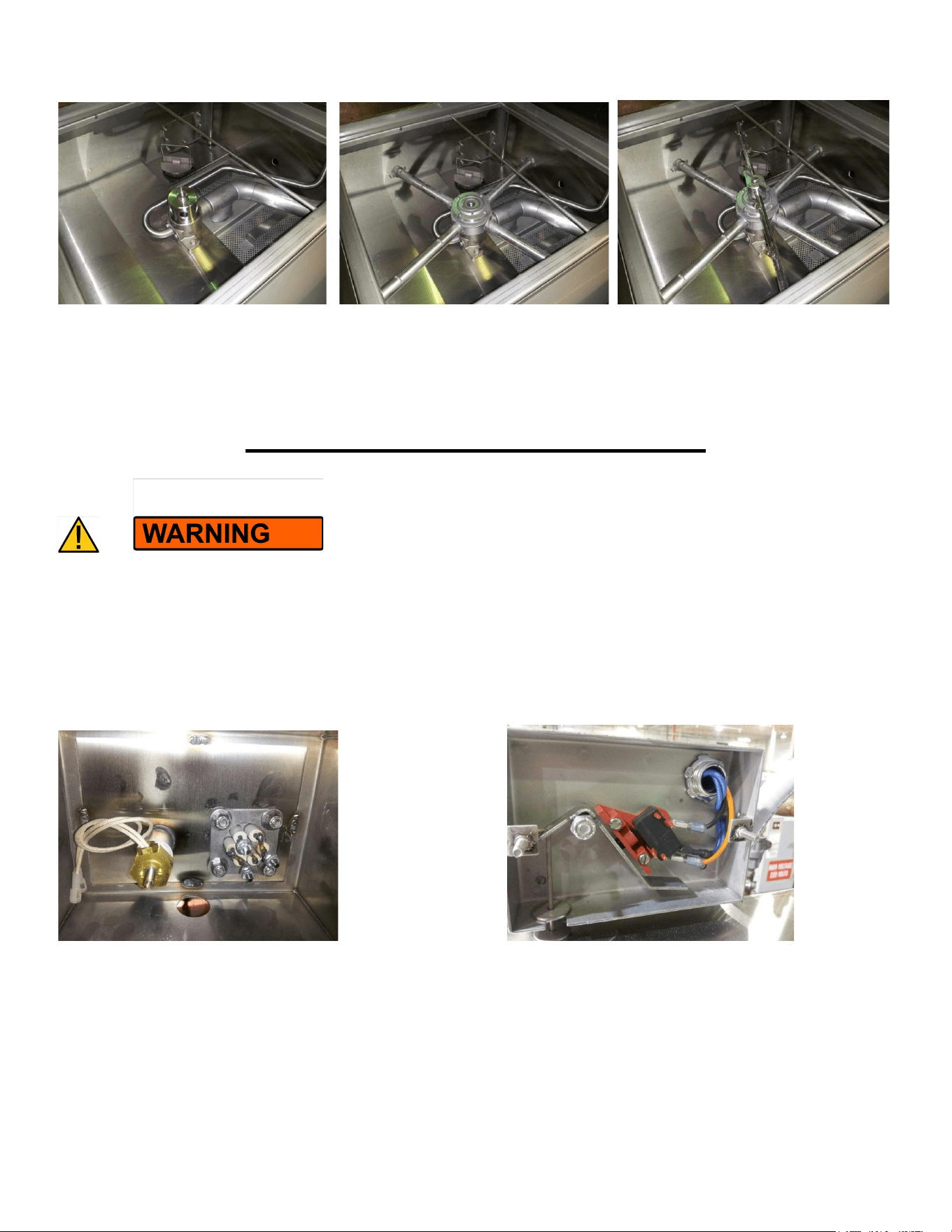
12
Showing spray arm base & transfer tube Wash arm w/bearing installed on base Final rinse arm twisted into transfer tube
Verify incoming water temperatures and final rinse pressure (20 psi during final rinse). Remove any of the
white protective film from stainless surfaces such as doors or panels.
DISHMACHINE OPERATIONAL TESTS
BURN HAZARD FROM HOT WATER. Do not open doors while machine is
in cycle. Doing so could result in serious bodily injury from spraying hot water and chemicals.
To operate, connect the breaker for main power and turn “ON” the dishmachine master switch. Water will
automatically fill to an operational level. After several cycles when final rinse water increases the tank water
level, the tank water will overflow to the scrap box. Place a rack of dishes in the machine, close the door and
the cycle will begin.
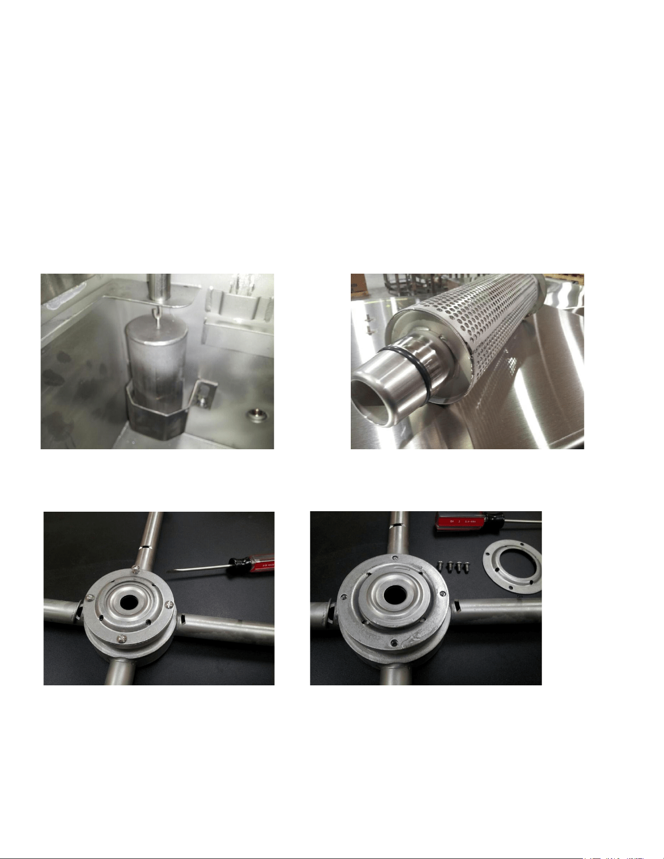
Showing thermostat and sustainer heater terminals* Showing “float” switch that controls fill water & heater
The wash temperature is maintained by a sustainer heater. Record tank temperature during the initial tests.
There are two gauges mounted under the control box. Gauges are marked Wash/Final Rinse. Wash tank
temperature should be 140F-degrees for chemical sanitizing and 160F-degrees for hot water sanitizing. If tank
temperatures are low, increase by adjusting the heater thermostat located behind the wash motor.*
Copyright ADS Installation Manual Model HT-25 (4 wire), Revision 3.1, 6/14/2017
13
Increase temp by turning center rod of the thermostat counter clock-wise or turn to left. Adjust thermostat in
small increments (1/4 turn). Heater is switched off when water levels are low and the fill has been activated.
Final rinse temperatures are 120F for chemical sanitizers, and 180F for hot water sanitizing. To increase the
final rinse temperatures turn up the thermostat on the booster heater or water heater respectively. Do not set
a booster heater above 195F. ADS DOES NOT SPECIFY BUILDING HVAC VALUES
“FLOAT” AND SWITCH—the float will not actually float. It is heavier than water but it weighs less in water than
in air. This difference allows the return spring in the float switch to push out against the lever, which raises the
float in water. In air the float weight will overcome the switch spring tension and drop down. The float switch
(#291-3014) is specifically made with this spring tension so the water control system will operate correctly. Do
not replace with a timer switch even though they look the similar.
Wash tank float and tank overflow Pump filter and drain plug, note O-ring seal
HT-25 WASH ARM BEARING REPLACEMENT OR CLEANING
Remove 4 screws and lift top shell Remove top shell, exposing top bearing race
Copyright ADS Installation Manual Model HT-25 (4 wire), Revision 3.1, 6/14/2017
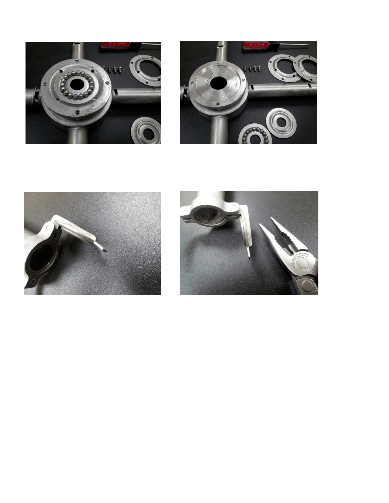
14
Top race removed, ball bearings for replacement Races are interchangeable, capture shells are also
Showing repair of loose end cap when tab on the cap has been forced close or bent on material such as seeds
or tooth picks.
Tab on endcap bent inward, causing loose fit Straighten tab in line with the coin edge to tighten
APPENDIX
089-9336---HT-25 Parts Manual
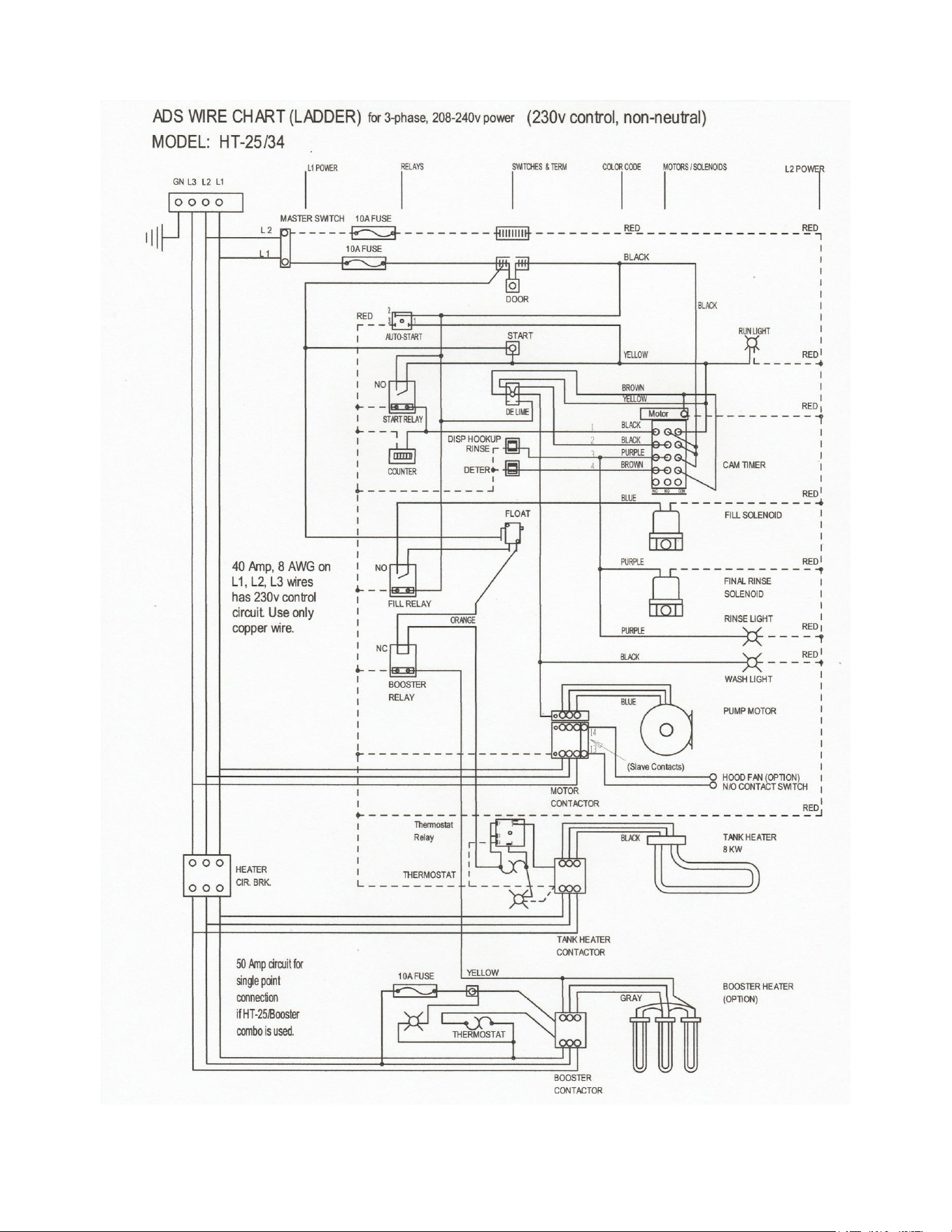
089-9450---Wire diagram
089-9404---Service Manual
089-9433---Brochure
089-9370---Wall Chart
089-9417---Spec Sheet
089-9378---Installation Manual HT-25 (4-wire)
Copyright ADS Installation Manual Model HT-25 (4 wire), Revision 3.1, 6/14/2017

15
HT-25 Single Tank High Temp
Voltage
Phas
e
Full Load Amps
208v
3
30.2
240v
3
33.5
HT-25 Single Tank High Temp
w/Booster
Voltage
Phas
e
Full Load Amps
208v
3
41.2
240v
3
36.9
Heaters are voltage specific, meaning voltage makes a difference in the wattage output of the heater. The
following chart will list the wattage (kW) output for various available 3-phase voltages. Also listed are the ADS
tank heaters available to match those voltages.
Heater
Rated
Supplied
Volts
Actual
Output
Amp Draw
Phase
12kW 208v
200 volts
11.1 kW
32.0a
3-ph
(291-9009)
208 volts
12.0 kW
33.4a
3-ph
240 volts
15.9 kW
38.4a
3-ph
12kW 220v
200 volts
9.9 kW
28.6a
3-ph
(291-9001)
208 volts
10.7 kW
29.7a
3-ph
220 volts
12.0 kW
33.4a
3-ph
240 volts
14.3 kW
34.4a
3-ph
8kW 208v
200 volts
7.4 kW
21.4a
3-ph
(391-9001)
208 volts
8.0 kW
22.2a
3-ph
220 volts
8.9 kW
23.4a
3-ph
240 volts
10.6 kW
25.5a
3-ph
Copyright ADS Installation Manual Model HT-25 (4 wire), Revision 3.1, 6/14/2017
16
Copyright ADS Installation Manual Model HT-25 (4 wire), Revision 3.1, 6/14/2017

17
WARNING!
This product is manufactured
solely for commercial use. It is
not to be used in residential
installations of any kind. Doing
so will immediately void all
warranties. American Dish
Service assumes no liability for
such unintended uses.
Copyright ADS Installation Manual Model HT-25 (4 wire), Revision 3.1, 6/14/2017

18
FOR PARTS &
SERVICE
MANUALS
GO TO
www.americandish.com
Copyright ADS Installation Manual Model HT-25 (4 wire), Revision 3.1, 6/14/2017

19
f. Overloads will operate in test mode
14. Control box cover fits square and straight, no pits or burns
a. Door will latch open and slide closed easily
b. Front skirt of machine: straight
15. No leaks from inlet plumbing, final rinse mixing chamber, or drain manifold
16. Water control Weight are free moving, no contact with retaining
bracket
a. Micro switch mounted flush to flipper lever
b. Micro switch tested and marked: 6.5 oz
c. Weights: 238 grams test
d. Water cut off level is 3/8" from weight's top
e. Weight's retaining bracket is installed and tightened
(no contact with weight itself)
______ f. Operate flipper 10 or 15 times, should not stay on when tank is full
17. Name plate with correct serial number
18. Decals: electrical source, NSF data plate, wire diagram, temperatures,
controls, safety, rotation, labels in control box. (all decals put on straight)
19. General appearance and cleanliness (free of scratches or marks)
20. Check all wire connections: tight, no crimps on insulation
21. Check door cut off switch adjustment
22. End caps welded correctly
a. 4 point welds on casting
b. All pins flash welded on only one side
______ c. Latch holds without binding
23. Check cycle light operation
24. Final rinse arms alignment correct, rotation must be
55 min / 70 max rpm @ 20psi
25. High Potential test: 1700 volts @ 60 seconds
26. Check all wires for loose connection
Special Notes:
______Make sure door moves up and down smoothly and
______Rinse jets are set to correct fan pattern
______End caps close and open securely
MODEL:__________________
MACHINE SERIAL NUMBER:______________
INSPECTORS NAME:____________________________________DATE:_________
Copyright ADS Installation Manual Model HT-25 (4 wire), Revision 3.1, 6/14/2017

20
PRODUCTION FINAL INSPECTION
AMERICAN DISH SERVICE
MODEL: HT-25
03/09/2020
1. Clean out all grit and shavings from inside, clean under tank heater also. Level machine
2. Connect power source, leave heater c/b and motor contactor off
3. Fill tank by turning on master switch
4. Check tray track (no binding)
a. Door moves easily and gently, up and down
b. Final rinse: clear jets, check for leaks at manifold
5. Check timer, finger movement and shut off of master, wash, and rinse
______ a. Check timer with order-- 45 sec or 60 sec
6. Check all studs (should not deform metal by drawing down on torque)
7. Turn on heater c/b, let tank equalize to temp. (Must maintain temp. through 5
operations)
a. Adjust thermostats to 120F min. wash for Chemical Sanitizing
160F min. wash for Hot Temp
180F min. for booster heater
b. Calibrate thermometers with thermocouple tester
8. Check door for leaking when wash pump is operated
9. Easy movement and rotation of spray arm as they are installed or removed for
cleaning
10. Scrap trays fit without binding or excessive gaps.
11. Check screws on bearing shells, no cross thread or slot deformation
12. Turn on heater circuit breaker
a. Check amp draw on each leg: wash heater:
21a-23.3a, 8kw, 3PH-208v
18.2a-20.1a, 8kw, 3PH-240v
36.6a-40.4a, 8kw, 1PH-208v
31.6a-34.9a, 8kw, 1PH-240v
Amp draw can vary 10% of rated draw at rated voltage. Current imbalance of 5% is acceptable
13. Connect motor on contactor test window and operate
a. Check rotation
b. Check for seal leaks
c. Amp draw test: wash motor: 9 amps, (3PH-208v)
8 amps, (3PH-240v)
15 amps (1PH-208v)
14 amps (1PH-240v)
d. Pressure test: Wash pump 6min-7max psi lower base,
______ lower 8min-9max psi upper base, rotation 60 rpm
______upper 10 seconds final rinse ______________sec.
Final rinse 20 psi (adjust at pressure reg.) Rotation: 60 rpm (visually check)
e. Check for leaks with machine running
Copyright ADS Installation Manual Model HT-25 (4 wire), Revision 3.1, 6/14/2017