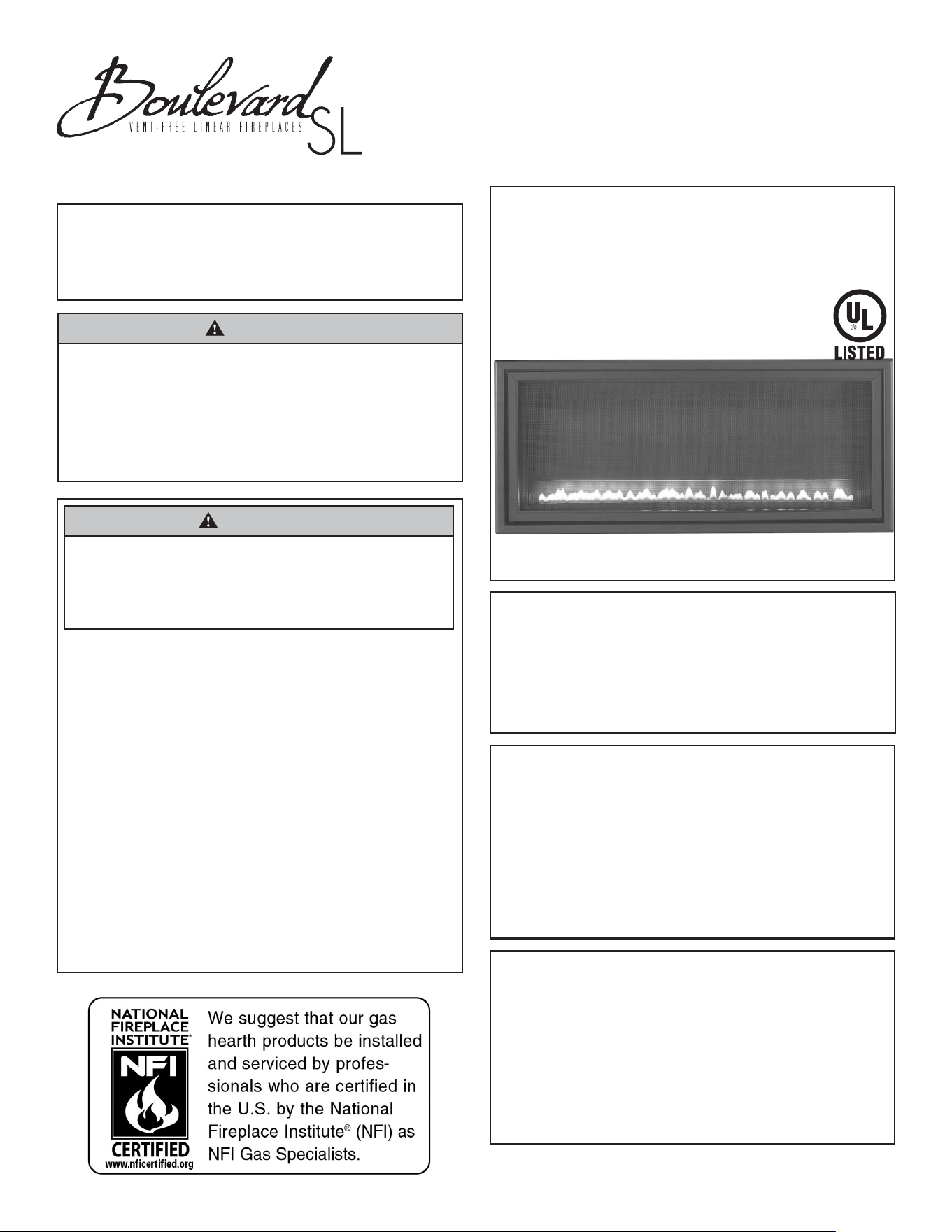
INSTALLATION INSTRUCTIONS
AND OWNER'S MANUAL
CONTEMPORARY LINEAR
VENT-FREE GAS FIREPLACE
MODELS
VFSL30FP7010(N,P)-1
VFSL30FP70(N,P)-1
VFSL30FP70 Shown
VFMH46389
GAS-FIRED
Installer: Leave this manual with the
appliance.
Consumer: Retain this manual for future
reference.
This appliance may be installed in
an aftermarket, permanently located,
manufactured (mobile) home, where not
prohibited by local codes.
This appliance is only for use with the type
of gas indicated on the rating plate. This
appliance is not convertible for use with
other gases.
WARNING
If the information in this manual is not
followed exactly, a re or explosion may
result causing property damage, personal
injury or loss of life.
— Do not store or use gasoline or other
ammable vapors and liquids in the
vicinity of this or any other appliance.
— WHAT TO DO IF YOU SMELL GAS
• Do not try to light any appliance.
• Do not touch any electrical switch; do
not use any phone in your building.
• Immediately call your gas supplier
from a neighbor’s phone. Follow the
gas supplier’s instructions.
• If you cannot reach your gas supplier,
call the re department.
— Installation and service must be
performed by a qualied installer,
service agency or the gas supplier.
This is an unvented gas-red heater. It uses
air (oxygen) from the room in which it is
installed.
Provisions for adequate combustion and
ventilation air must be provided. Refer to
page 13.
WATER VAPOR: A BY-PRODUCT OF
UNVENTED ROOM HEATERS
Water vapor is a by-product of gas
combustion. An unvented room heater
produces approximately one (1) ounce
(30ml) of water for every 1,000 BTU's
(.3KW's) of gas input per hour. Refer to
page 13.
DANGER
If not installed, operated and maintained
in accordance with the manufacturer's
instructions, this product could expose
you to substances in fuel or from fuel
combustion which can cause death or
serious illness.
Page 1

35775-0-0915Page 2
TABLE OF CONTENTS
BEFORE YOU START .......................................................................................................... 3
HOMEOWNER REFERENCE INFORMATION .................................................................... 4
CARTON CONTENTS .......................................................................................................... 4
HARDWARE PACK CONTENTS ......................................................................................... 5
IMPORTANT SOOT PREVENTION STEPS ........................................................................ 6
PRODUCT SPECIFICATIONS ............................................................................................. 6
INTRODUCTION .................................................................................................................. 7
ACCESSORIES.................................................................................................................... 8
IMPORTANT SAFETY INFORMATION .........................................................................9 - 10
SAFETY INFORMATION FOR USERS OF LP GAS .......................................................... 11
IMPORTANT INSTALLATION GUIDELINES ...................................................................... 12
WATER VAPOR: A BY-PRODUCT OF UNVENTED ROOM HEATERS ............................ 13
PROVISIONS FOR ADEQUATE COMBUSTION & VENTILATION AIR .....................13 - 14
SURFACE MOUNTED FIREPLACE ........................................................15 - 21
SURFACE MOUNTED FIREPLACE DIMENSIONS ....................................................16 - 17
SURFACE MOUNTED FIREPLACE INSTALLATION .................................................18 - 21
PARTIALLY RECESSED FIREPLACE ....................................................23 - 31
PARTIALLY RECESSED FIREPLACE DIMENSIONS ................................................24 - 25
PARTIALLY RECESSED FIREPLACE INSTALLATION .............................................. 26 - 31
RECESSED FIREPLACE ........................................................................33 - 41
RECESSED FIREPLACE DIMENSIONS ....................................................................34 - 35
RECESSED FIREPLACE INSTALLATION ..................................................................36 - 41
GAS SUPPLY ..............................................................................................................42 - 43
COMBUSTIBLE MATERIALS ............................................................................................. 43
MANTEL CLEARANCES .................................................................................................... 44
CLEANING AND SERVICING ............................................................................................ 45
LIGHTING INSTRUCTIONS ............................................................................................... 46
PILOT FLAME CHARACTERISTICS .................................................................................47
OPERATING INSTRUCTIONS / FLAME APPEARANCE .................................................. 47
IP OPERATING INSTRUCTIONS ...................................................................................... 48
IP WIRING ..........................................................................................................................49
ELECTRICAL CONSIDERATIONS .................................................................................... 50
IP TROUBLESHOOTING ............................................................................................51 - 53
PARTS LIST ....................................................................................................................... 54
EXPLODED VIEW .............................................................................................................. 55
MASTER PARTS DISTRIBUTOR LIST .............................................................................. 56
HOW TO ORDER REPAIR PARTS .................................................................................... 56
APPLIANCE SERVICE HISTORY ............................................................................... 57 - 58
WARRANTY .......................................................................................................................59
SECTION PAGE
35775-0-0915 Page 3
BEFORE YOU START
1. Record serial number, model number, etc. on the next page
and page 56.
2. Read the soot-prevention information on page 6.
3. Read the safety information on pages 9 - 11.
4. Determine type of installation. See illustrations on this page.
5. Verify clearances to combustibles. See pages 43 - 44.
6. Determine type of gas shutoff valve to use.
7. Frame the opening.
• SurfaceMountedInstallation:Noopeningrequired.
• PartiallyRecessedInstallation:Seepage27.
• RecessedInstallation:Seepage37.
8. Install the gas line basics. See page 42 - 43.
9. Install the Fireplace.
• SurfaceMountedInstallation:Seepages15-21.
• PartiallyRecessedInstallation:Seepages23-31.
• RecessedInstallation:Seepage33-41.
10. Install the wiring. See page 49.
11. Perform a Leak Test. See page 42.
12. Lightthereplace.Seepages46.
13. Showthehomeownerhowtooperatethereplace.
14. Show the homeowner how to do the basic maintenance.
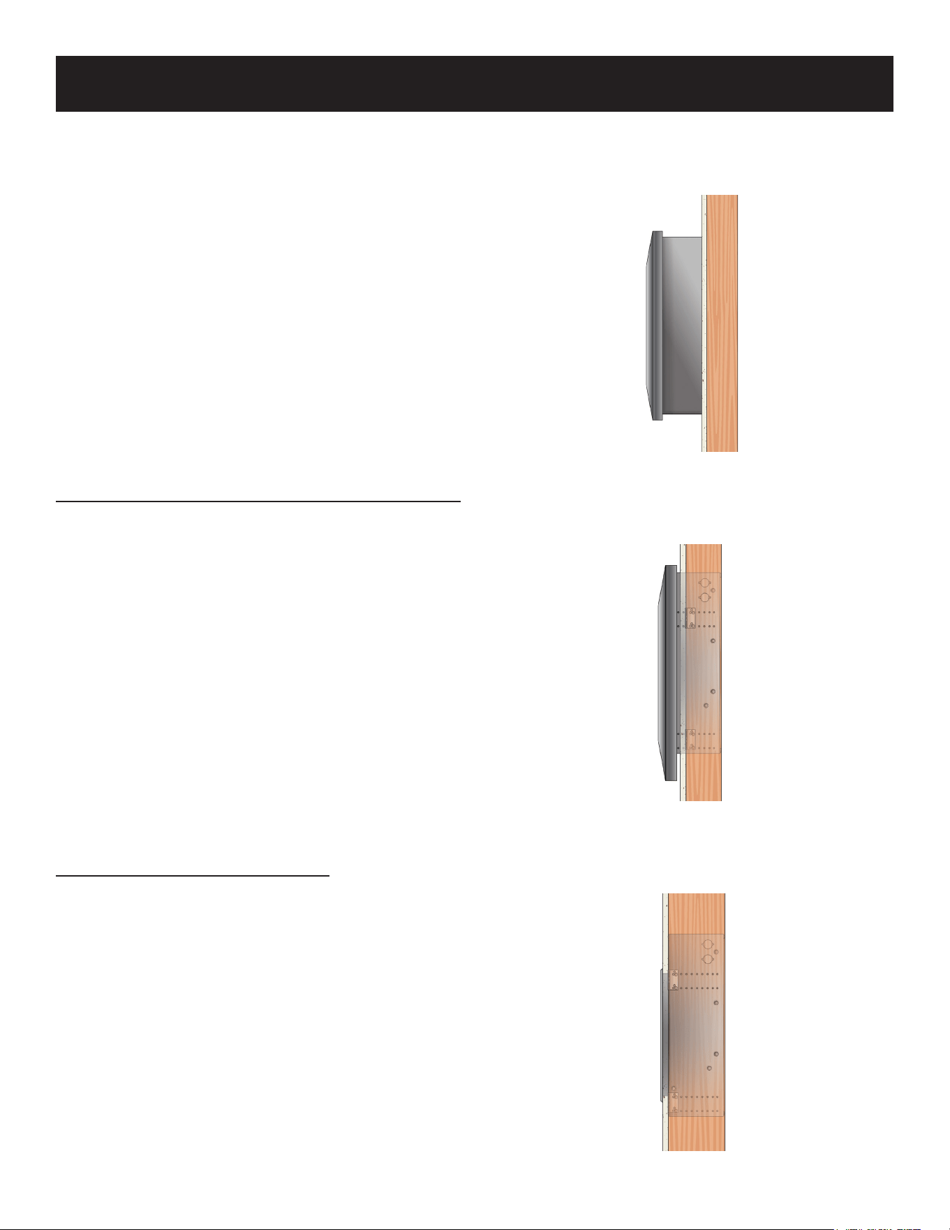
Installation Considerations - Fireplace Installation Guidelines
Nopartofthereplace,gasline,orwiringmaybeinstalledina
wall cavity serving as a cold air return.
Inplanningtheinstallationforthereplace,determinewherethe
unitistobeinstalled.Thereplacecanbemountedthreeways:
1. Surface mounted on a wall.
2. Partially recessed in a 2 x 4 or 2 x 6 wall.
3. Recessed in a 2 x 6 wall.
Fireplace must only be permanently installed on or in a wall.
This unit is designed to be installed in a zero-clearance
enclosure. This means the combustible material can come in
contact with the top standoff (recessed in a 2 x 6 wall installation
only)orreplacetop(partiallyrecessed),bottom,andsecuredto
combustibleframingusingthenailingangeprovided.
Determine the following before installation:
• Installationtype
• Anydesiredaccessories
• Gassupplypiping(leftsideaccess).
• Electricalsupplyrequirementsforpoweradaptor.
(120V, 60Hz, 1 Amp) (right side access)
Operating the Fireplace for the First Time
Duringmanufacture,thisreplaceistreatedwithoils,lmsand
bonding agents. These are not harmful but may produce smoke
andodorastheyburnoffduringinitialoperationofthereplace.
This is normal. Open a window during the initial bake out
period. The following procedure will cure the materials used to
manufacturethereplace.
• Thereplaceshouldberunthreetofourhourscontinuously.
• Turnthereplaceoffandallowittocompletelycool.
• Cleantheglass.
NOTICE:Openwindowsforaircirculationduringreplacebreak-
in.
• Somepeoplemaybesensitivetosmokeandodors.
• Smokedetectorsmayactivate.
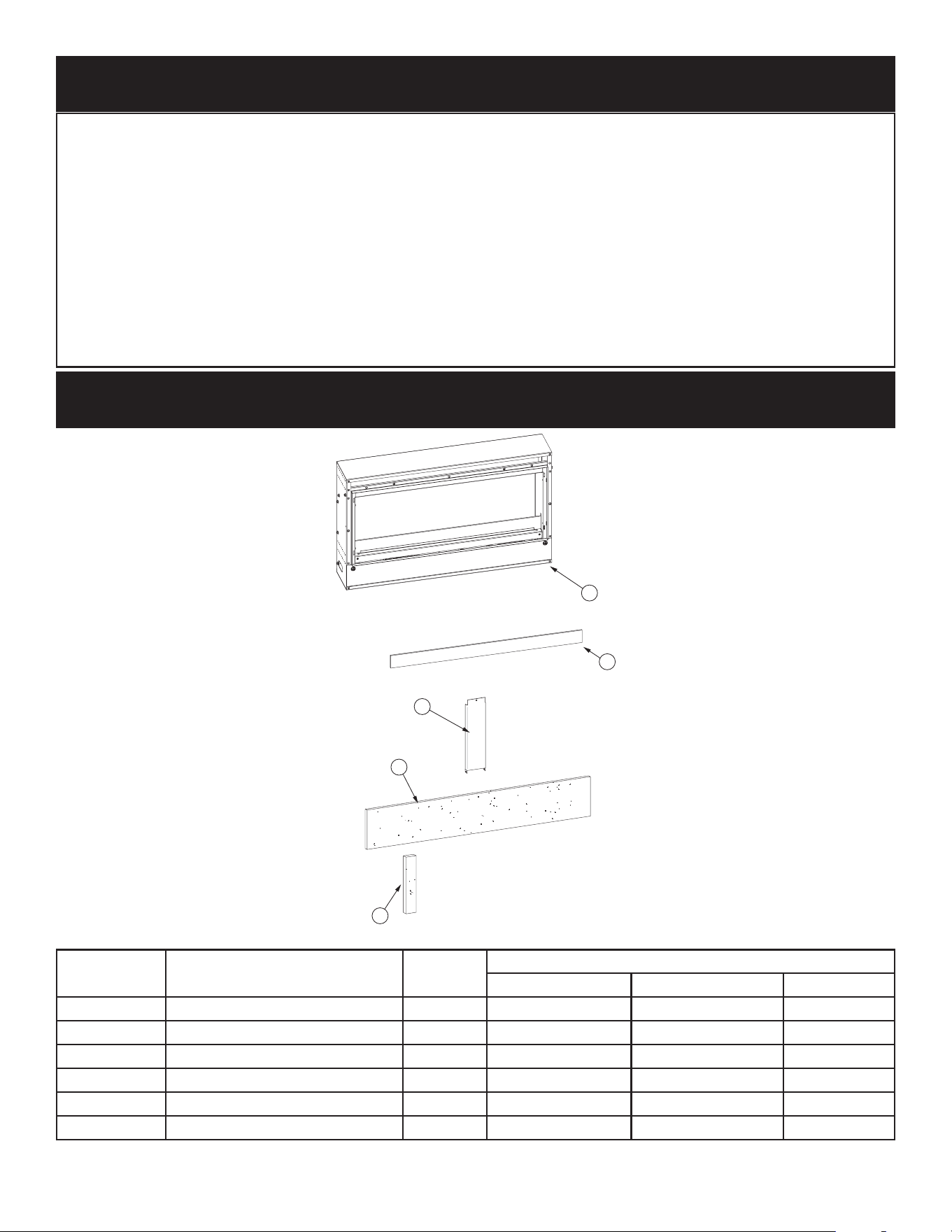
INSTALLATION TYPE
SURFACE MOUNTED INSTALLATION
Pages 15 - 21
PARTIALLY RECESSED INSTALLATION
Pages 23 - 31
RECESSED INSTALLATION
Pages 33 - 41
35775-0-0915Page 4
HOMEOWNER REFERENCE INFORMATION
Werecommendthatyourecordthefollowinginformationaboutyourreplace.
Model Number: _____________________________ Date purchased: ________________________
Serial Number: _____________________________ Locationofreplace: _____________________
Dealer Name: ______________________________ Dealer Phone: _________________________
Notes: ______________________________________________________________________________
____________________________________________________________________________________
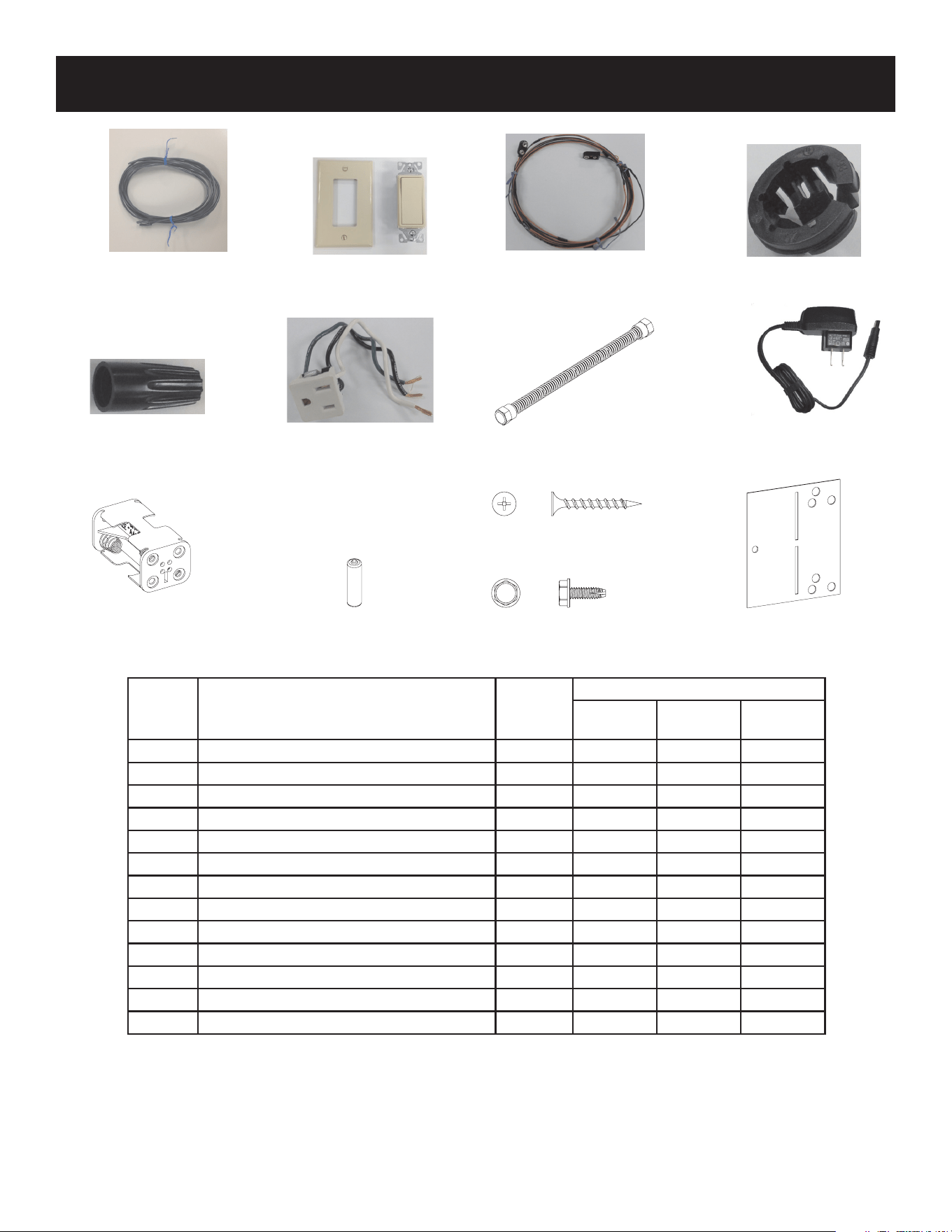
CARTON CONTENTS
2
3
5
1
4
Items not shown to scale.
Index No. Description Quantity Used On Installation Type:
Surface Mounted Partially Recessed Recessed
1 Fireplace 1 YES YES YES
2 Non-combustible board - Top 1 NO YES YES
3 Non-combustible board - Side 2 NO NO YES
4 Glass Panel 1 YES YES YES
5 Standoff 1 NO NO YES
Not Shown Hardware Pack 1 YES YES YES
See Parts Lists on page 54 for ordering replacement parts. Do not order batteries, bolts, screws, washers or nuts. They are standard
hardware items and can be purchased at any local hardware store.
35775-0-0915 Page 5
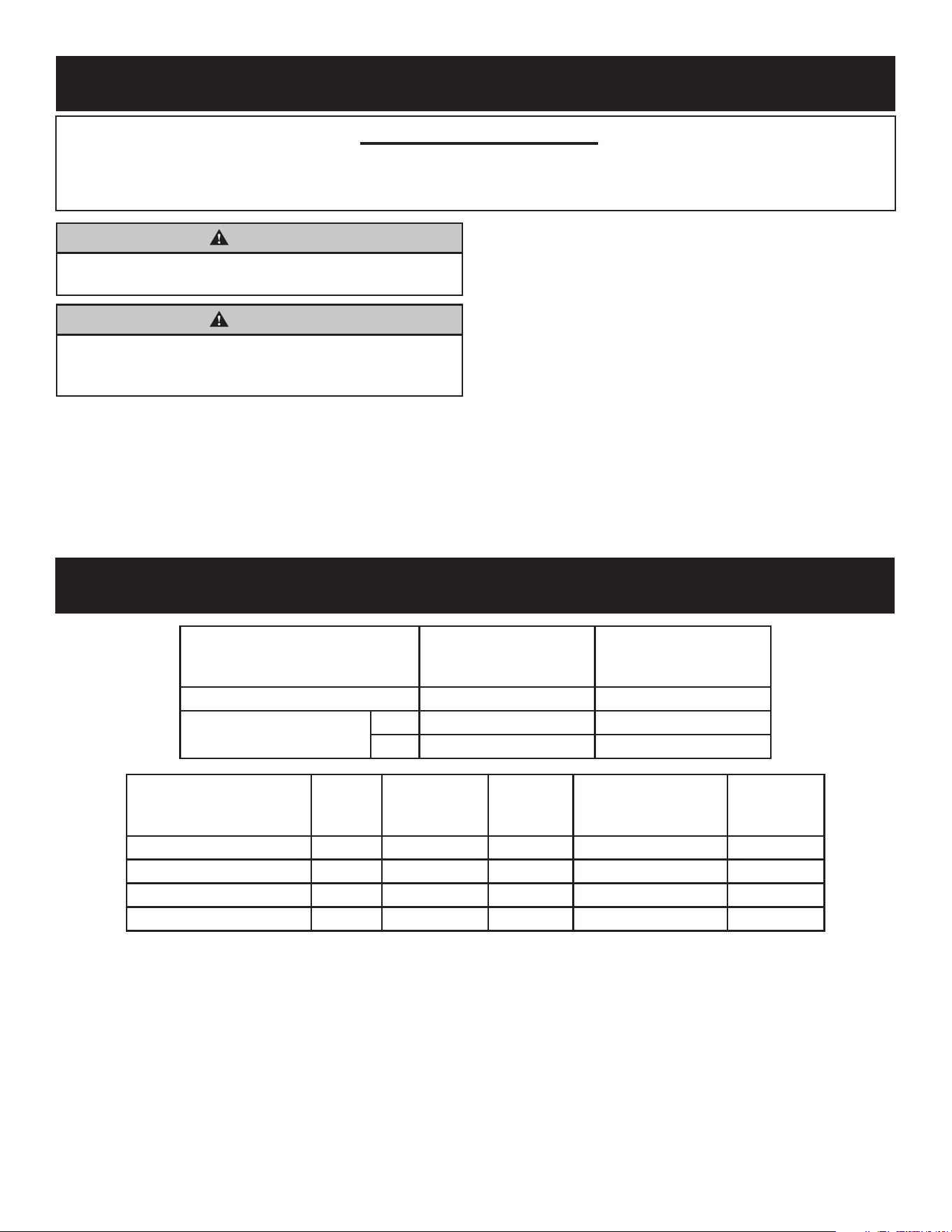
HARDWARE PACK CONTENTS
Items not shown to scale.
Index
Number
Description
Quantity
Supplied
Used On Installation Type:
Surface
Mounted
Partially
Recessed
Recessed
1 Switch Extension Wire Kit 1 YES YES YES
2 Switch and Cover 1 YES YES YES
3 Battery Pack Extension Wire Kit 1 YES YES YES
4 Cord Grip 2 YES YES YES
5 Wire Nut 2 YES YES YES
6 Snap-In Receptacle 1 YES YES YES
7 Flex Line 1 YES YES YES
8 AC Power Adaptor 1 YES YES YES
9 Battery Pack 1 YES YES YES
10 AA Battery 4 YES YES YES
11 #10-32 x 1/2 inch Hex Head Screw* 10 NO YES YES
12 1-1/4 inch Phillips Drywall Screw* 16 NO YES YES
13 Nailing Flange 4 NO YES YES
* Not all of the screws will be used on each installation.
See Parts Lists on page 54 for ordering replacement parts. Do not order batteries, bolts, screws, washers or nuts. They are standard
hardware items and can be purchased at any local hardware store.
1-1/4” PHILLIPS DRYWALL SCREW
#10-32 X ½” HEX HEAD SCREW
NAILING FLANGES
SWITCH EXTENSION WIRE KIT
BATTERYPACK EXTENSION WIRE KIT
CORD GRIP
FLEX LINE
WIRE NUT
SWITCH AND COVER
BATTERYPACK
AA BATTERY
SNAP-IN RECEPTACLE
POWER ADAPTER
VFSL30\CDR\Hardware Pack Contents -111815
35775-0-0915Page 6
CAUTION
Failure to keep the primary air openings of the burner
clean may result in sooting and property damage.
CAUTION
Donotallowfanstoblowdirectlyintooratthereplace.
Avoidanydraftsthatalterburneramepatterns.Pay
particular attention to ceiling fans and exhaust fans.
IMPORTANT SOOT PREVENTION STEPS
IMPORTANT NOTICE
INSTALLER - SERVICE PERSON - HOMEOWNER
SOOT MAY BE CREATED IF THE FOLLOWING DIRECTIONS ARE NOT FOLLOWED.
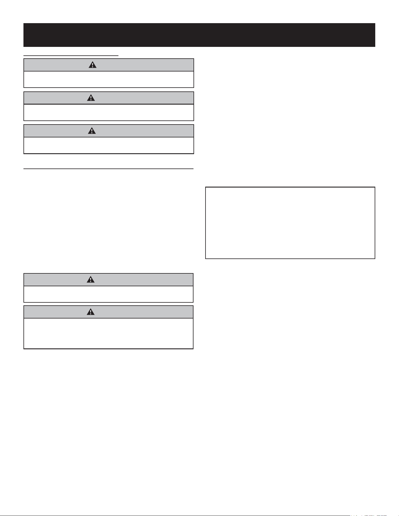
PRODUCT SPECIFICATIONS
VFSL30FP(70,7010)N
Natural Gas
(inches w.c.)
VFSL30FP(70,7010)P
Propane Gas
(inches w.c.)
Manifold pressure setting 3.5 10.0
Gas inlet pressure
Max. 10.5 13.0
Min. 5.0 11.0
Model
Gas
Type
Valve Type Orice
Recommended
Manifold Pressure
(inches w.c.)
BTUH
Max. Rate
VFSL30FP70P LP IP #60 10.0 12,000
VFSL30FP70N NAT IP #50 3.5 14,000
VFSL30FP7010P LP IP #64 10.0 10,000
VFSL30FP7010N NAT IP 1.50mm 3.5 10,000
• Ensureburnerandprimaryairholesarefreeofdust,
lint, animal hair (i.e. cat and dog) or anything that may
blocktheneededairow.SeeCleaningandServicing,
page 45.
• Donotplaceanythingontheburnerincludinglogs,
rock wool, decorative glass, etc.
• Donotusescentedairfreshenersorcandleswhilethe
replaceisinoperation.Theycancausesoot.
• Haveyourdealerorqualiedservicetechnician
perform an annual inspection and cleaning to prevent
malfunction or sooting.
• Verifytheburnertubeisnotbentordistorted.The
mainburneroricemustbecenteredintheburner
tube for proper combustion to prevent sooting.
35775-0-0915 Page 7
INTRODUCTION
Important
All correspondence should refer to complete Model Number and
Serial Number.
Notice: Duringinitialringofthisreplace,itspaintwillbakeout,
and smoke will occur. To prevent triggering of smoke alarms,
ventilate the room in which the unit is installed.
Qualied Installing Agency
Installation and replacement of gas piping, gas utilization
equipmentoraccessoriesandrepairandservicingofequipment
shallbeperformedonlybyaqualiedagency.Theterm"qualied
agency"meansanyindividual,rm,corporationorcompany
which either in person or through a representative is engaged
in and is responsible for (a) the installation or replacement of
gas piping or (b) the connection, installation, repair or servicing
ofequipment,whoisexperiencedinsuchwork,familiarwithall
precautionsrequiredandhascompliedwithalltherequirements
of the authority having jurisdiction.
Commonwealth of Massachusetts: The installation must be
madebyalicensedplumberorgastterintheCommonwealth
of Massachusetts.
Sellersofunventedpropaneornaturalgas-redsupplemental
replacesshallprovidetoeachpurchaseracopyof527CMR
30 upon sale of the unit.
In the Sate of Massachusetts, unvented propane and natural
gas-redspaceheatersshallbeprohibitedinbedroomsand
bathrooms.
The installation must conform with local codes or, in the absence
of local codes, with the National Fuel Gas Code, ANSI Z223.1.*
*Available from the American National Standards Institute, Inc.
1430 Broadway, New York, N.Y. 10018.
High Altitudes
For altitudes/elevations above 2,000 feet (610m), ratings should
be reduced at the rate of 4 percent for each 1,000 feet (305m)
above sea level. Contact the manufacturer or your gas company
beforechangingoricesize.
Well Head Gas Installations
Somenaturalgasutilitiesuse"wellhead"gas.Thismayaffect
the Btu output of the unit. Contact the gas company for the
heating value. Then, contact the manufacturer to verify what
oriceisneededforoperationofthereplace.
Sample Warnings and Denitions:
DANGER
Indicates a hazardous situation which, if not avoided, will result
in death or serious injury.
WARNING
Indicates a hazardous situation which, if not avoided, could
result in death or serious injury.
CAUTION
Indicates a hazardous situation which, if not avoided, could
result in minor or moderate injury.
NOTICE: Addresses practices not related to personal injury.
Instructions to Installer
1. Leave instruction manual with owner after installation.
2. Haveownerlloutproductregistrationcardsuppliedwiththe
vent-freereplace.
3. Showownerhowtostartandoperatethereplace.
Consult your local Building Department regarding regulations,
codes or ordinances which apply to the installation of an
unventedreplace.
Thisreplacemaybeinstalledinanaftermarket*manufactured
(mobile) home, where not prohibited by state or local codes.
*Aftermarket: Completion of sale, not for purpose of resale,
from the manufacturer.
WARNING
Thisapplianceisequippedfornaturalorpropanegas.Field
conversion is not permitted.
WARNING
Anychangetothisreplaceoritscontrolscanbedangerous.
Improperinstallationoruseofthereplacecancauseserious
injuryordeathfromre,burns,explosionorcarbonmonoxide
poisoning.
Thisreplaceseriesisdesigncertiedinaccordancewith
American National Standard Institute (ANSI) Z21.11.2 by the
Canadian Standards Association Laboratories (CSA) as an
Unvented Room Heater and should be installed according to
these instructions.
Any alteration of the original design, installed other than as
shown in these instructions or use with a type of gas not
shown on the rating plate is the responsibility of the person
and company making the change.
35775-0-0915Page 8
ACCESSORIES
Required Accessories for Surface Mounted Installation
Decorative Front (One Required)
Part Number Description
DFSL30MBL Decorative Front - Mitered, Black
DFSL30VBL Decorative Front - Convex, Black
Decorative Wrap (One Required)
DCSL30LBL Decorative Wrap - Black
Required Accessories for Partially Recessed Installation
Decorative Front (One Required)
Part Number Description
DFSL30MBL Decorative Front - Mitered, Black
DFSL30VBL Decorative Front - Convex, Black
Optional Accessory for Recessed Installation
Part Number Description
DFSL30PBL Decorative Trim - Black
Optional Control Accessories - All Installation Types
Part Number Description
FRBC* Battery Remote, ON/OFF
FRBTC* Battery Remote, Thermostat
FRBTP* Programmable Remote
TRW* Wireless Wall Thermostat
TMV Wall Thermostat - Reed Switch
*Requiresjunctionboxoutsideofthereplace.
Attention: Certainaccessoriesarerequired,butsoldseparately.
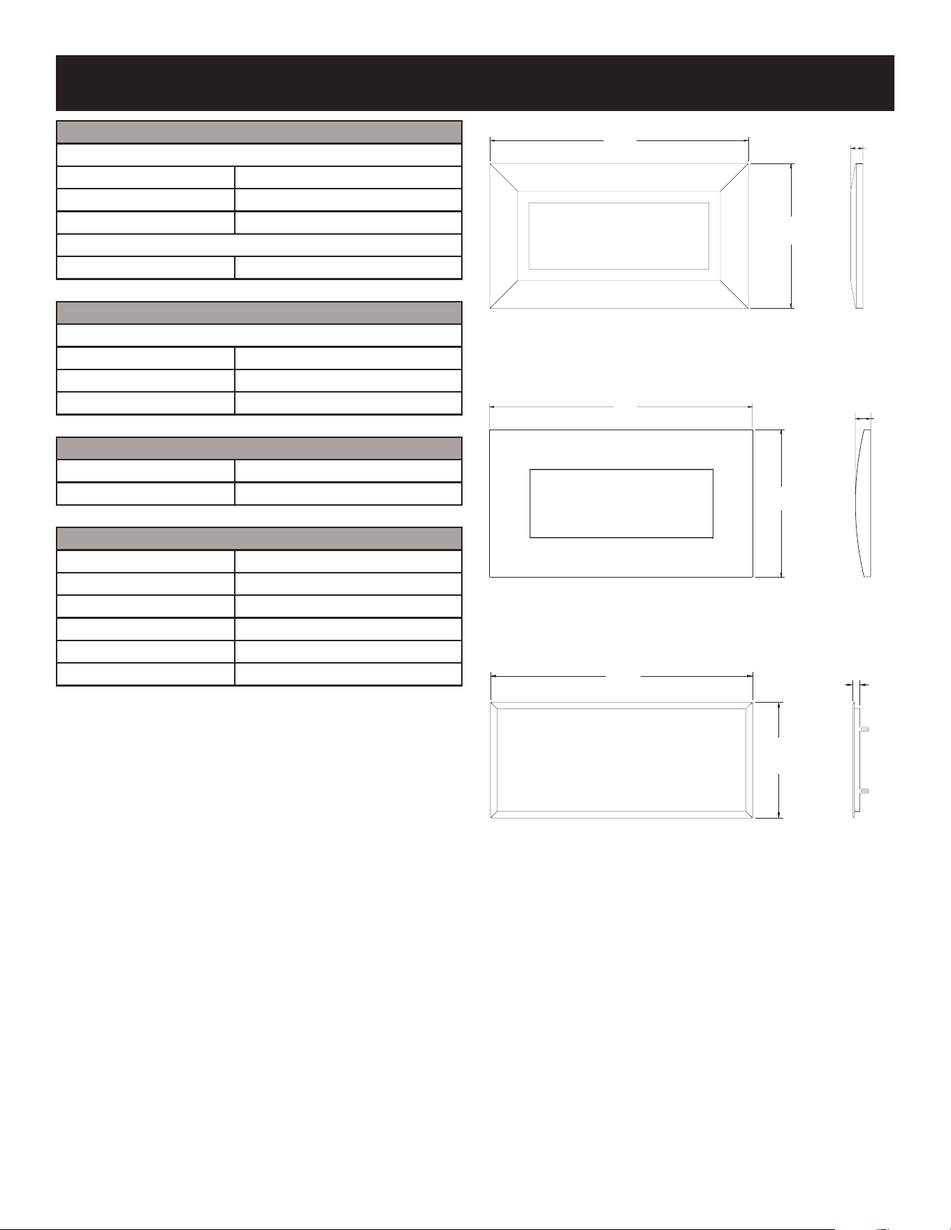
Mitered Front Dimensions
21-3/32”
37-13/16”
1-13/16
”
Convex Front Dimensions
21-1/4”
37-7/8”
2-1/4
”
Wall Trim Dimensions
13-5/32”
29-3/4”
13/16
”
35775-0-0915 Page 9
WARNING
Whenusedwithoutadequatecombustionandventilationair,
appliance may give off CARBON MONOXIDE, an odorless,
poisonous gas.
Do not install appliance until all necessary provisions are
made for combustion and ventilation air. Consult the written
instructions provided with the appliance for information
concerning combustion and ventilation air. In the absence
of instructions, refer to the National Fuel Gas Code, ANSI
Z223.1/NFPA 54, Air for Combustion and Ventilation, or
applicable local codes.
ThisapplianceisequippedwithaPILOT LIGHT SAFETY
SYSTEM designed to turn off the appliance if not enough fresh
air is available.
Do not tamper with pilot light safety system!
Ifreplaceshutsoff,donotrelightuntilyouprovidefreshair.
Ifreplacekeepsshuttingoff,haveitserviced.Keepburner
and control compartment clean. See installation and operating
instructions accompanying heater.
Carbon monoxide poisoning may lead to death.
Earlysignsofcarbonmonoxidepoisoningresembletheu,with
headache, dizziness and/or nausea. If you have these signs,
replacemaynotbeworkingproperly.Get fresh air at once!
Havereplaceserviced.
Some people — pregnant women, persons with heart or lung
disease,anemia,thoseundertheinuenceofalcohol,those
at high altitudes — are more affected by carbon monoxide than
others.
DANGER
The installer of this product is responsible for testing all
connections for gas leaks. A gas leak will create a situation
whereare,explosion,orproductionofcarbonmonoxidemay
result causing property damage, personal injury or loss of life.
WARNING
Do not use a blower insert, heat exchanger insert or other
accessory not approved for use with this heater.
WARNING
Thisreplaceneedsfreshairforventilationtorunproperly.
ThisreplacehasanPilotLightSafetySystem(Oxygen
DepletionSensor-ODS)whichwillshutdownthereplaceif
adequatefreshairisnotavailable.Seetroubleshootingsection
in the instructions.
WARNING
Donotallowfanstoblowdirectlyintooratthereplace.Avoid
anydraftsthatalterburneramepatterns.
WARNING
DONOToperatethisreplaceunlessallcomponentsincluding
burners and controls are in good working condition.
Replacement components are available through your local
dealer as indicated in the How to Order Repair Parts section of
thereplacemanual.
WARNING
Failure to keep the primary air opening(s) of the burner(s) clean
may result in sooting and property damage.
IMPORTANT SAFETY INFORMATION

35775-0-0915Page 10
• Donotusescentedairfresheners(plugintypeair
fresheners,etc.)whilethereplaceisinoperation.Air
fresheners produce a residue in the air similar to candles
and may produce soot.
• Donotusescentedordecorativecandleswhilethereplace
is in operation. Candles produce a residue in the air that
createssoot.Burningcandleswhilethereplaceisoperating
magniestheproblem.Itshouldbenotedthatcandles,in
general, produce soot. The amount of time burned and the
quantityofcandlesburnedwilldeterminetheamountofsoot
produced and deposited.
• Installation and repair should be done by a QUALIFIED
SERVICE PERSON. Thisreplaceshouldbeinspected
before use and at least annually by a professional service
person.Morefrequentcleaningmayberequireddueto
excessive lint from carpeting, bedding materials, etc. It
is imperative that control compartments, burners and
circulatingairpassagewaysofthereplacebekeptclean.
• Donotplacedebris,logsorotherarticlesontheburner
during operation.
• Donotinstallanunventedroomreplacewithaninputrating
of more than 6,000 Btu per hour in a bathroom.
• Donotinstallanunventedroomreplacewithaninputrating
of more than 10,000 Btu per hour in a bedroom or bathroom.
• Duetohightemperatures,thereplaceshouldbelocatedout
oftrafcandawayfromfurnitureanddraperies.
• Alertchildrenandadultstothehazardofhighsurface
temperatures. High surface temperatures can cause burns or
ignite clothing.
• Youngchildrenshouldbecarefullysupervisedwhentheyarein
thesameroomwiththereplace.
• Donotplaceclothingorotherammablematerialonornear
thereplace.
• DONOTuse this room heater if any part has been under
water.Immediatelycallaqualiedservicetechnicianto
inspect the room heater and to replace any part of the
control system and any gas control which has been under
water.
• Youmustoperatereplacewithglasspanelinplace.
• Duringmanufacture,thisreplaceistreatedwithcertainoils,
lmsandbondingagents.Thesebondingagentsarenot
harmful but may produce annoying smoke and odors as they
areburnedoffduringinitialoperationofthereplace.Thisis
a normal temporary occurrence. A window should be opened
during the initial bake out period.
• Keepreplaceareaclearandfreefromcombustible
materials,gasolineandotherammablevaporsandliquids.
• Sooting: Avent-freereplaceorburnerdrawsroomairto
support combustion. Lightweight particles suspended in the
air–includingdust,carpetbers,candleortobaccosmoke,
andpethair–willbedrawntowardthereplace.Thesecan
leadtosootbuilduponreplacewallsandevenwallsofthe
room. To prevent malfunctions and sooting, have your dealer
perform an inspection and cleaning each year – before the
heating season. If you have pets or excessive dust, more
frequentcleaningmaybenecessary.Seecleaningand
service section in this manual.
• UseNon-CombustibleMaterialswhereindicatedforthe
replaceinstallation.Non-combustiblematerialdonot
igniteorburnasaresultofusingthereplace.These
include metal, brick, ceramic, concrete, slate, glass, and
plaster. Adhesives must be rated for high temperatures. Any
mechanical fasteners used to install material must also be
non-combustible, including wall anchors and tile spacers.
Materials that pass the ASTM E 136 test (Standard Test
Method for Behavior of Materials in a Vertical Tube Furnace
at 750C) are considered non-combustible.
• Combustiblematerialsincludewood,compressedpaper,
plantbers,orothermaterialsthatwillburn.Thesematerials
areconsideredcombustibleevenwhentreatedwithre-
retardantchemicals.See"ClearancestoCombustibles"for
your installation.
• Donotplaceembers(rockwool)orlavarocksinthis
replace.
• Avoidanydraftsthatalterburneramepatterns.Donot
allowfanstoblowdirectlyintooratthereplace.Donot
placeablowerinsidetheburnerareaoftherebox.Ceiling
fansmaycreatedraftsthatalteramepatterns.Sootingand
improper burning will result.
• Installingatelevisionaboveareplacehasbecomea
desirable feature; however, the following information should
be considered.
Allreplaces,whetherdecorativeorheaterrated,create
heat. Most television manufacturers recommend not placing
a television near a heat source. Because there is a large
variety of television manufacturers, styles and sizes, it is
impractical to test every potential installation. If you install
atelevisionabovethisreplace,EmpireComfortSystems
accepts no responsibility for damage or injuries. Follow the
television manufacturer’s installation instructions, including
any recommendations regarding proximity to heat sources.
IfyouhaveaTVaboveyourreplace,turnoffthereplace
and let it cool completely before servicing or touching any
buttons on the TV. In all cases, the television manufacturer’s
instructions and warnings should be followed.
IMPORTANT SAFETY INFORMATION

35775-0-0915 Page 11
SAFETY INFORMATION FOR USERS OF LP GAS
Propane (LP Gas) is a ammable gas which can cause res
and explosions. In its natural state, propane is odorless
and colorless. You may not know all the following safety
precautions which can protect both you and your family
from an accident. Read them carefully now, then review
them point by point with the members of your household.
Someday when there may not be a minute to lose,
everyone’s safety will depend on knowing exactly what
to do. If, after reading the following information, you feel
you still need more information, please contact your gas
supplier.
LP GAS WARNING ODOR
If a gas leak happens, you should be able to smell the gas
because of the odorant put in the LP Gas.
That's your signal to go into immediate action!
• Donotoperateelectricswitches,lightmatches,useyour
phone. Do not do anything that could ignite the gas.
• Geteveryoneoutofthebuilding,vehicle,trailer,orarea.Do
that IMMEDIATELY.
• Closeallgastankorcylindersupplyvalves.
• LPGasisheavierthanairandmaysettleinlowareassuch
as basements. When you have reason to suspect a gas leak,
keep out of basements and other low areas. Stay out until
reghtersdeclarethemtobesafe.
• Useyourneighbor’sphoneandcallatrainedLPGasservice
personandtheredepartment.Eventhoughyoumaynot
continue to smell gas, do not turn on the gas again. Do not
re-enter the building, vehicle, trailer, or area.
• Finally, lettheservicemanandreghterscheckfor
escaped gas. Have them air out the area before you return.
Properly trained LP Gas service people should repair the
leak,thencheckandrelightthegasreplaceforyou.
NO ODOR DETECTED - ODOR FADE
Some people cannot smell well. Some people cannot smell
the odor of the chemical put into the gas. You must nd
out if you can smell the odorant in propane. Smoking can
decrease your ability to smell. Being around an odor for a time
can affect your sensitivity or ability to detect that odor. Sometimes
other odors in the area mask the gas odor. People may not smell
the gas odor or their minds are on something else. Thinking
about smelling a gas odor can make it easier to smell.
The odorant in LP Gas is colorless, and it can fade under
some circumstances. For example, if there is an underground
leak,themovementofthegasthroughsoilcanltertheodorant.
Odorants in LP Gas also are subject to oxidation. This fading can
occur if there is rust inside the storage tank or in iron gas pipes.
The odorant in escaped gas can adsorb or absorb onto or into
walls, masonry and other materials and fabrics in a room. That
will take some of the odorant out of the gas, reducing its odor
intensity.
LP Gas may stratify in a closed area, and the odor intensity could
vary at different levels. Since it is heavier than air, there may be
more odor at lower levels. Always be sensitive to the slightest
gas odor. If you detect any odor, treat it as a serious leak.
Immediately go into action as instructed earlier.
SOME POINTS TO REMEMBER
• LearntorecognizetheodorofLPGas.YourlocalLPGas
Dealer can give you a “Scratch and Sniff” pamphlet. Use it
tondoutwhatthepropaneodorsmellslike.Ifyoususpect
that your LP Gas has a weak or abnormal odor, call your LP
Gas Dealer.
• Ifyouarenotqualied,donotlightpilotlights,perform
service,ormakeadjustmentstoreplacesontheLP-Gas
system.Ifyouarequalied,consciouslythinkabouttheodor
of LP Gas prior to and while lighting pilot lights or performing
service or making adjustments.
• Sometimesabasementoraclosed-uphousehasamusty
smell that can cover up the LP Gas odor. Do not try to light
pilot lights, perform service, or make adjustments in an area
where the conditions are such that you may not detect the
odor if there has been a leak of LP-Gas.
• Odorfade,duetooxidationbyrustoradsorptiononwalls
of new cylinders and tanks, is possible. Therefore, people
should be particularly alert and careful when new tanks or
cylinders are placed in service. Odor fade can occur in new
tanks,orreinstalledoldtanks,iftheyarelledandallowed
tosettoolongbeforerelling.Cylindersandtankswhich
have been out of service for a time may develop internal rust
which will cause odor fade. If such conditions are suspected
to exist, a periodic sniff test of the gas is advisable. If you
have any question about the gas odor, call your LP
Gas dealer. A periodic sniff test of the LP Gas is a good
safety measure under any condition.
• If,atanytime,youdonotsmelltheLPGasodorantand
you think you should, assume you have a leak. Then take
the same immediate action recommended above for the
occasion when you do detect the odorized LP Gas.
• Ifyouexperienceacomplete“gasout,”(thecontainer
is under no vapor pressure), turn the tank valve off
immediately. If the container valve is left on, the container
may draw in some air through openings such as pilot light
orices.Ifthisoccurs,somenewinternalrustingcouldoccur.
If the valve is left open, then treat the container as a new
tank. Always be sure your container is under vapor pressure
by turning it off at the container before it goes completely
emptyorhavingitrelledbeforeitiscompletelyempty.
35775-0-0915Page 12
Fans and Cold Air Returns Near the Fireplace
Anydraftcreatedaroundavent-freereplacecancausethe
ametocreatesoot.Uponinstallation,beawareofanycoldair
returnsorventsintheproximityofthereplace.Ceilingfansand
oortypefansneedtobemonitoredduringtheoperationofthis
vent-freereplace.Iftheairowdisruptstheame,thesource
ofairowshouldbeturnedofforredirected.Reversingtheblade
directionceilingfansmaypossiblyeliminateameimpingement.
Floor fans should be redirected.
WARNING
Donotallowfanstoblowdirectlyintooratthereplace.Avoid
anydraftsthatalterburneramepatterns.
NOTICE: Nopartofthereplace,gasline,orwiringmaybe
installed in a wall cavity serving as a cold air return.
Candles
Avoidtheuseofscentedordecorativecandleswhilethereplace
is in operation. Candles produce a residue in the air that creates
soot.Burningcandleswhilethereplaceisoperatingmagnies
the problem. It should be noted that candles, in general,
producesoot.Theamountoftimeburnedandthequantityof
candles burned will determine the amount of soot produced and
deposited.
Plug-In Air Fresheners
Avoidtheuseofscentedairfreshenerswhilethereplaceisin
operation. Air fresheners produce a residue in the air similar to
candles and may produce soot.
Television Considerations
Installingatelevisionaboveareplacehasbecomeincreasingly
popular;however,theareaaboveanyreplacegetshotandmost
TV manufacturers recommend against placing their products
near a heat source.
Ifyouinstallatelevisionabovethisreplace,EmpireComfort
Systems accepts no responsibility for damage or injuries. Follow
the television manufacturer’s installation instructions, including
any recommendations regarding proximity to heat sources.
IfyouhaveaTVaboveyourreplace,turnoffthereplaceand
let it cool completely before servicing or touching any buttons on
the TV.
IMPORTANT INSTALLATION GUIDELINES

35775-0-0915 Page 13
Water vapor is a by-product of gas combustion. An unvented
room heater produces approximately one (1) ounce (30ml) of
water for every 1,000 BTU's (.3KW's) of gas input per hour.
Unventedroomreplacearerecommendedassupplemental
heat (a room) rather than a primary heat source (an entire
house). In most supplemental heat applications, the water vapor
does not create a problem. In most applications, the water vapor
enhances the low humidity atmosphere experienced during cold
weather.
The following steps will help insure that water vapor does not
become a problem.
1. Besurethereplaceissizedproperlyfortheapplication,
including ample combustion air and circulation air.
2. Ifhighhumidityisexperienced,adehumidiermaybeusedto
help lower the water vapor content of the air.
3. Donotuseanunventedroomheaterorreplaceasthe
primary heat source.
Thisreplaceshallnotbeinstalledinaroomorspaceunless
therequiredvolumeofindoorcombustionairisprovidedbythe
method described in the National Fuel Gas Code, ANSI Z23.1/
NFPA 54, the International Fuel Gas Code, or applicable local
codes.
Installation in a Conned Space
Aconnedspaceisanareawithvolumelessthan50cubic
feetper1,000Btuhofthecombinedinputratesofallreplaces
drawing combustion air from that space. Small areas such as
equipmentroomsareconnedspaces.Furnacesinstalledin
aconnedspacewhichsupplyheatedairtoareasoutsidethe
space must draw return air from outside the space through tightly
sealedreturnairducts.Aconnedspacemusthave2openings
into the space for combustion air. One opening must be within
12 inches of the ceiling and the other must be within 12 inches
oftheoor.Therequiredsizingoftheseopeningsisdetermined
by whether inside or outside air is used to support combustion,
the method by which the air is brought to the space (vertical or
horizontalduct)andbythetotalinputrateofallreplacesinthe
space.
Unusually Tight Construction
The air that leaks around doors and windows may provide
enough fresh air for combustion and ventilation. However, in
buildings of unusually tight construction, you must provide
additional fresh air.
Unusually tight construction is dened as construction
where:
a. Walls and ceilings exposed to the outside atmosphere
have a continuous water vapor retarder with a rating of
one perm or less with openings gasketed or sealed, and
b. Weather-stripping has been added on openable windows
and doors, and
c. Caulking or sealants are applied to areas such as joints
around window and door frames, between sole plates and
oors,betweenwall-ceilingjoints,betweenwallpanels,at
penetrations for plumbing, electrical, and gas lines, and at
other openings.
If your home meets all of the three criteria above, you must
provide additional fresh air. See “Ventilation Air From
Outdoors,” page 14.
Determining if You Have a Conned or Unconned Space
Usethisworksheettodetermineifyouhaveaconnedor
unconnedspace.
Space:Includestheroominwhichyouwillinstallreplaceplus
any adjoining rooms with doorless passageways or ventilation
grills between the rooms.
1. Determine the volume of the space (length x width x height).
Length x Width x Height =
cu. ft. (volume of
space)
Example: Space size 16 ft. (length) x 10 ft. (width) x 8 ft.
(ceiling height) = 1,280 cu. ft. (volume of space)
If additional ventilation to adjoining room is supplied with
grills or openings, add the volume of these rooms to the total
volume of the space.
2. Divide the space volume by 50 cu. ft. to determine the
maximum BTU/hr the space can support.
(volume of space) ÷ 50 cu. ft. = (maximum
BTU/hr the space can support)
Example: 1,280 cu. ft. (volume of space) ÷ 50 cu. ft. = 25.6 or
25,600 (maximum BTU/hr the space can support)
3. AddtheBTU/hrofallfuelburningreplacesinthespace.
Vent-freereplace
BTU/hr
Gas water heater BTU/hr
Gas furnace BTU/hr
Ventedgasreplace BTU/hr
Gasreplacelogs BTU/hr
Othergasreplaces* + BTU/hr
Total = BTU/hr
Example: Ventedgasreplace 20,000 BTU/hr
Vent-freereplace + 18,000 BTU/hr
Total = 38,000 BTU/hr
*Donotincludedirect-ventgasreplaces.Directventdraws
combustion air from the outdoors and vents to the outdoors.
4. Compare the maximum BTU/hr the space can support with the
actual amount of BTU/hr used.
BTU/hr (maximum the space can support)
BTU/hr (actual amount of BTU/hr used)
Example:
25,600 BTU/hr (maximum the space can support)
38,000 BTU/hr (actual amount of BTU/hr used)
WARNING
Iftheareainwhichthereplacemaybeoperatedissmaller
thanthatdenedasanunconnedspaceorifthebuildingisof
unusuallytightconstruction,provideadequatecombustionand
ventilation air by one of the methods described in the National
Fuel Gas Code, ANSI Z223.1/NFPA 54, Air for Combustion and
Ventilation, or applicable local codes.
WATER VAPOR: A BY-PRODUCT OF UNVENTED ROOM HEATERS
PROVISIONS FOR ADEQUATE COMBUSTION & VENTILATION AIR
35775-0-0915Page 14
PROVISIONS FOR ADEQUATE COMBUSTION & VENTILATION AIR (continued)
Thespaceintheexampleonpage12isaconnedspace
because the actual BTU/hr used is more than the maximum BTU/
hr the space can support. You must provide additional fresh air.
Your options are as follows:
A. Rework worksheet, adding the space of an adjoining room. If
theextraspaceprovidesanunconnedspace,removedoor
to adjoining room or add ventilation grills between rooms.
See Ventilation Air From Inside Building.
B. Vent room directly to the outdoors. See Ventilation Air
From Outdoors.
C. InstallalowerBTU/hrreplace,iflowerBTU/hrsizemakes
roomunconned.
If the actual BTU/hr used is less than the maximum BTU/hr the
spacecansupport,thespaceisanunconnedspace.Youwill
need no additional fresh air ventilation.
Ventilation Air
Ventilation Air From Inside Building
Thisfreshairwouldcomefromanadjoiningunconnedspace.
Whenventilatingtoanadjoiningunconnedspace,youmust
provide two permanent openings: one within 12 inches of
theceilingandonewithin12inchesoftheooronthewall
connecting the two spaces (see options 1 and 2, Figure 1). You
can also remove door into adjoining room (see option 3, Figure
1). Each ventilation grill or opening shall have a minimum free
areaofonesquareinchper1,000BTUHofthetotalinputrating
ofthegasequipmentintheconnedspace.
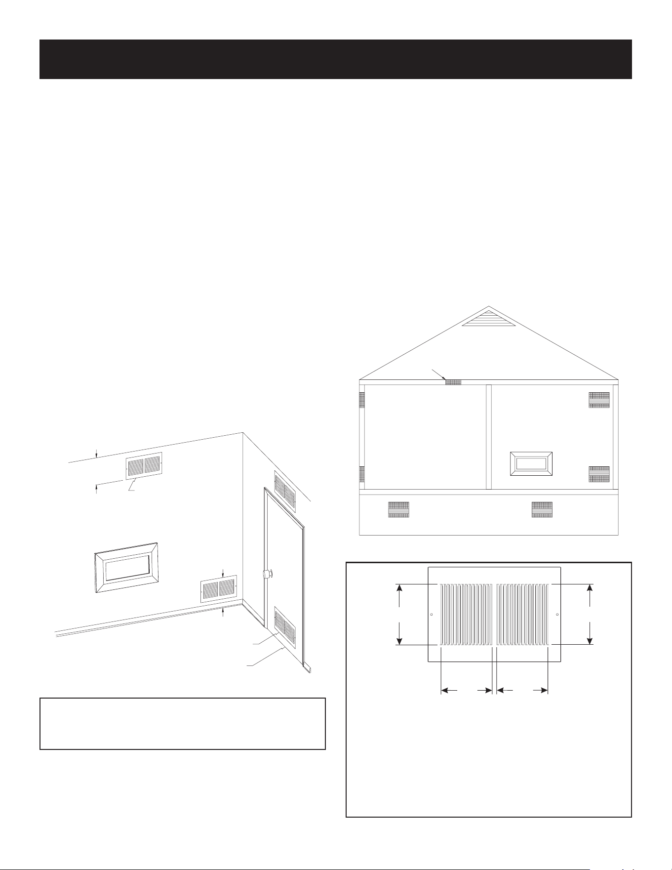
12”
(305mm)
OPTION 1.
VENTILATION GRILLS
INTO ADJOINING ROOM
12”
(305mm)
OPTION 2. VENTILATION GRILLS
INTO ADJOINING ROOM
OPTION 3. REMOVE DOOR INTO ADJOINING ROOM
Figure 1
Rework worksheet on page 13, adding the space of the
adjoining unconned space. The combined spaces must
have enough fresh air to supply all appliances in both
spaces.
Ventilation Air From Outdoors
Provide extra fresh air by using ventilation grills or ducts. You
must provide two permanent openings: one within 12 inches of
theceilingandonewith12inchesoftheoor.Connectthese
items directly to the outdoors or spaces open to the outdoors.
These spaces include attics and crawl spaces. In most cases for
direct communication with the outdoors or direct communication
throughaverticalductafreeareaopeningofonesquareinchper
4,000BTU/hrofreplaceinputratingforeachgrill.Ifahorizontal
duct is used, a grill free area or duct opening shall have a free
areaopeningofonesquareinchper2,000BTU/hrforeachgrill.
Follow the National Fuel Code ANSI Z223.1/NFPA54, Air for
Combustion and Ventilationforrequiredsizeofventilationgrills
or ducts.
IMPORTANT: Do not provide openings for inlet or outlet air into
attic if attic has a thermostat-controlled power vent. Heated air
entering the attic will activate the power vent.
OUTLET
AIR
OUTLET
AIR
VENTILATED
ATTIC
INLET
AIR
TO
ATTIC
TO
CRAWL
SPACE
INLET
AIR
VENTILATED
CRAWL SPACE
Figure 2
A1 A2
B1
B2
A1 x B1 = C1
A2 x B2 = C2
C1+C2=Sq.In.Required
Example:Fora30,000BTUFireplace,1sqinper1,000BTU
equals30sq.in.ofopening.
(A1) 5in
2
x (B1) 3in
2
= (C1) 15in
2
(A2) 5in
2
x (B2) 3in
2
= (C2) 15in
2
(C1) 15in
2
+(C2)15in
2
= 30in
2
Figure 3
35775-0-0915 Page 15
SURFACE MOUNTED FIREPLACE
35775-0-0915Page 16
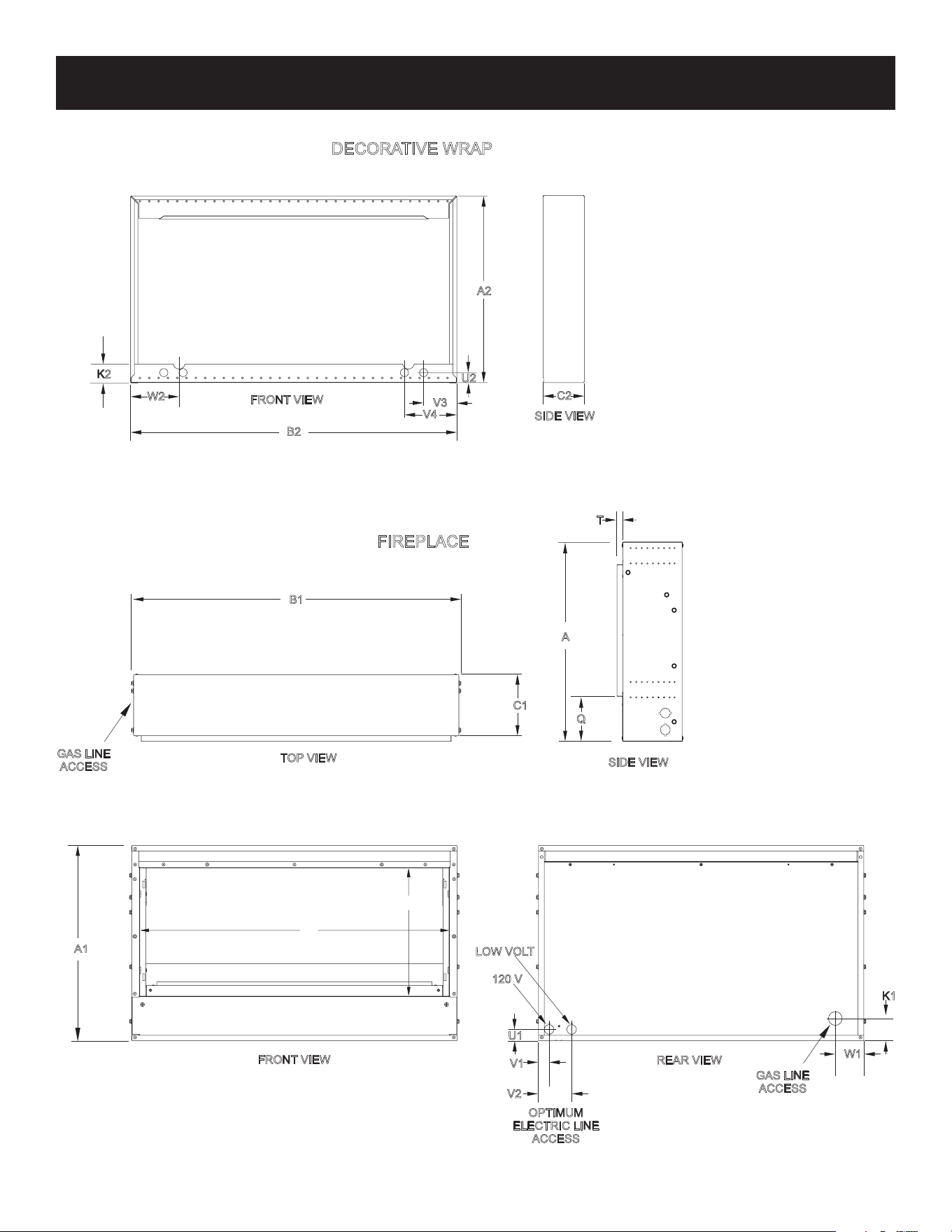
SURFACE MOUNTED FIREPLACE DIMENSIONS
GAS LINE
ACCESS
REAR VIEW
K1
W1
U1
V1
V2
OPTIMUM
ELECTRIC LINE
ACCESS
LOW VOLT
120 V
A1
E
D
FRONT VIEW
A
T
Q
SIDE VIEW
C1
B1
GAS LINE
ACCESS
TOP VIEW
K2
W2
B2
V3
V4
U2
A2
C2
FRONT VIEW
SIDE VIEW
FIREPLACE
DECORATIVE WRAP

35775-0-0915 Page 17
INDEX
LETTER
DIMENSION DESCRIPTION
VFSL30FP
Dimensions in Inches
A1 Themaximumheightofreplaceface 17-7/8
A2 The maximum height of decorative wrap 20
B1 Themaximumwidthofthereplaceface 30-1/4
B2 The maximum width of decorative wrap 35
C1 Themaximumdepthofthereplace 5-1/2
C2 The maximum depth decorative wrap 4-1/2
D Theheightofthereplaceopening 11-3/4
E Thewidthofthereplaceopening 28-3/8
F Theinteriordepthofthereplace(notshown) 4-3/16
K1 Heightfromthebottomofthereplacetothegaslineaccess 2-1/16
K2 Height from the bottom of the decorative wrap to the gas line access 2-1/16
N Glasspanelheight(notshown)inreplace 2
O Glasspanelwidth(notshown)inreplace 27-1/2
Q Distancefromoortoreplaceopening 4-1/16
T Openinglipofreplace 9/16
U1 Heighttoelectricalaccessofreplace 1-1/16
U2 Height to electrical access of decorative wrap 1-1/16
V1 Distancefromrightsideofreplaceto120Vaccess 1
V2 Distancefromrightsideofreplacetolow-voltageaccess 3-1/16
V3 Distance from right side of decorative wrap to 120V access 3-9/16
V4 Distance from right side of decorative wrap to low voltage access 5-5/8
W1 Distancefromleftsideofreplacetogasaccess 2-5/8
W2 Distance from left side of decorative wrap to gas access 5-1/4
SURFACE MOUNTED FIREPLACE DIMENSIONS
35775-0-0915Page 18
SURFACE MOUNTED FIREPLACE INSTALLATION
Provided Materials:
Fireplace
Battery Pack with 10-ft extension wire
(4) AA Batteries
AC Power Adaptor
Gas Flexline
Glass Panel
(2) Cord Grip
(2) Wire Nut
Snap-in Receptacle
ON/OFF Switch with 10-ft extension wire and cover (or other
control accessory - sold separately)
Required Materials - Not Provided:
Decorative Front (Sold Separately, contact your Empire Dealer)
Decorative Wrap (Sold Separately, contact your Empire Dealer)
Shutoff Valve
(2) Electrical Junction Boxes (external)
Junction Box Cover (external)
120V Wire
Gas Piping
(4) 2 inch Cabinet Drywall Screw
Tools Needed:
Level
Drill/Phillips Screwdriver
Wrenches
LeakDetectionLiquid
Tape Measure
DANGER
ThisreplacemustbeinstalledbyadealerorcertiedNational
Fireplace Institute technician. A professional will understand
therequirementsforgas,electrical,andframingneedsforthis
installation.
Step 1: Find location for replace and install decorative
wrap.
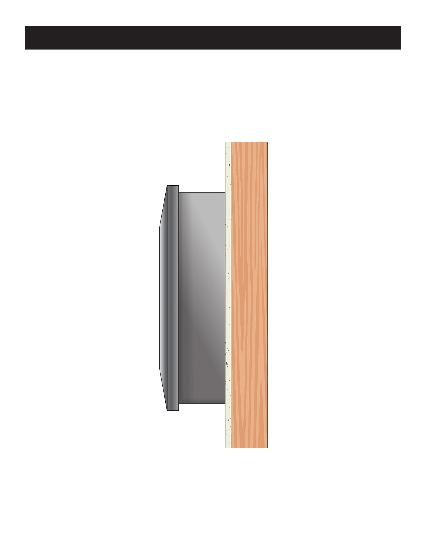
1. Surface-mountedinstallationmeansthatthereplacewill
be completely outside of the wall. In selecting a location, be
cautious of electrical wires, air ducts, water pipes, cold air
returns, etc. that may make gas line or electric installation
difcult.
2. See Clearances to Combustibles, pages 43 - 44.
3. Once the location has been found, arrange for gas lines
toruntothereplace.Allgaslinesmustbeinstalledbya
qualiedinstaller.Ashut-offvalvemusttobeincludedinthe
gas line installation. Follow local codes for installing the gas
line and shutoff valve.
4. Arrangefora120Vlinetoruntotherightofthereplace.
5. To ensure the proper location of the gas line and electrical
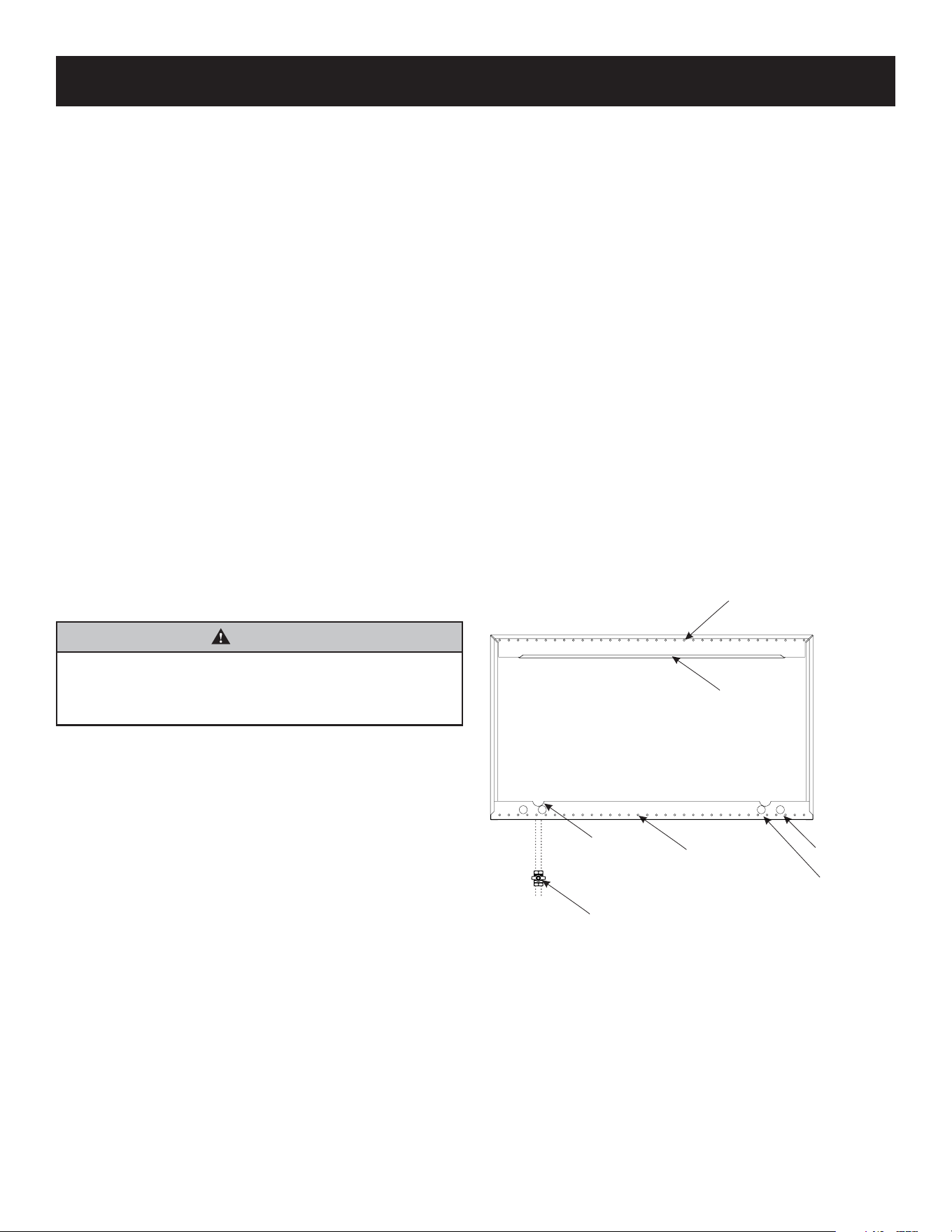
line, install the decorative wrap. See Figure 4.
a. Locate two studs behind the decorative wrap.
b. Start one cabinet screw into a stud on the top set of
holes, but leave screw loose. Place the level under
the hook and level the wrap. Insert the second cabinet
screw into the other stud on the top set of holes. Tighten
both screws.
c. Place the level on the side of the wrap along the rear
wall. When the side is plumb, insert two cabinet screws
into studs in the bottom set of mounting holes.
d. Testthesquarenessofthewrapbymeasuringthe
diagonals. The diagonal distances must match.
GAS INLET
BOTTOM
MOUNTING HOLES
LOW-VOLT
AGE
ACCESS
120V ACCESS
HOOK FOR
FIREPLACE
TOP MOUNTING HOLES
SHUT OFF VALVE
(NOT PROVIDED)
Figure 4
6. The decorative wrap can be used as a template for locating
the gas inlet and wiring locations.
7. Bringgaslinewithshutoffvalvelocatedoutsideofreplace
and 120V power to the locations indicated above. Gas line
mustbeinstalledbyaqualiedinstaller.
NOTICE for this application only: The battery back-up
may be placed inside the decorative wrap outside of the
replace'srightside.Forthistypeofinstallation,onlyone
junctionboxandswitchextensionwireharnessisrequired.
35775-0-0915 Page 19
SURFACE MOUNTED FIREPLACE INSTALLATION
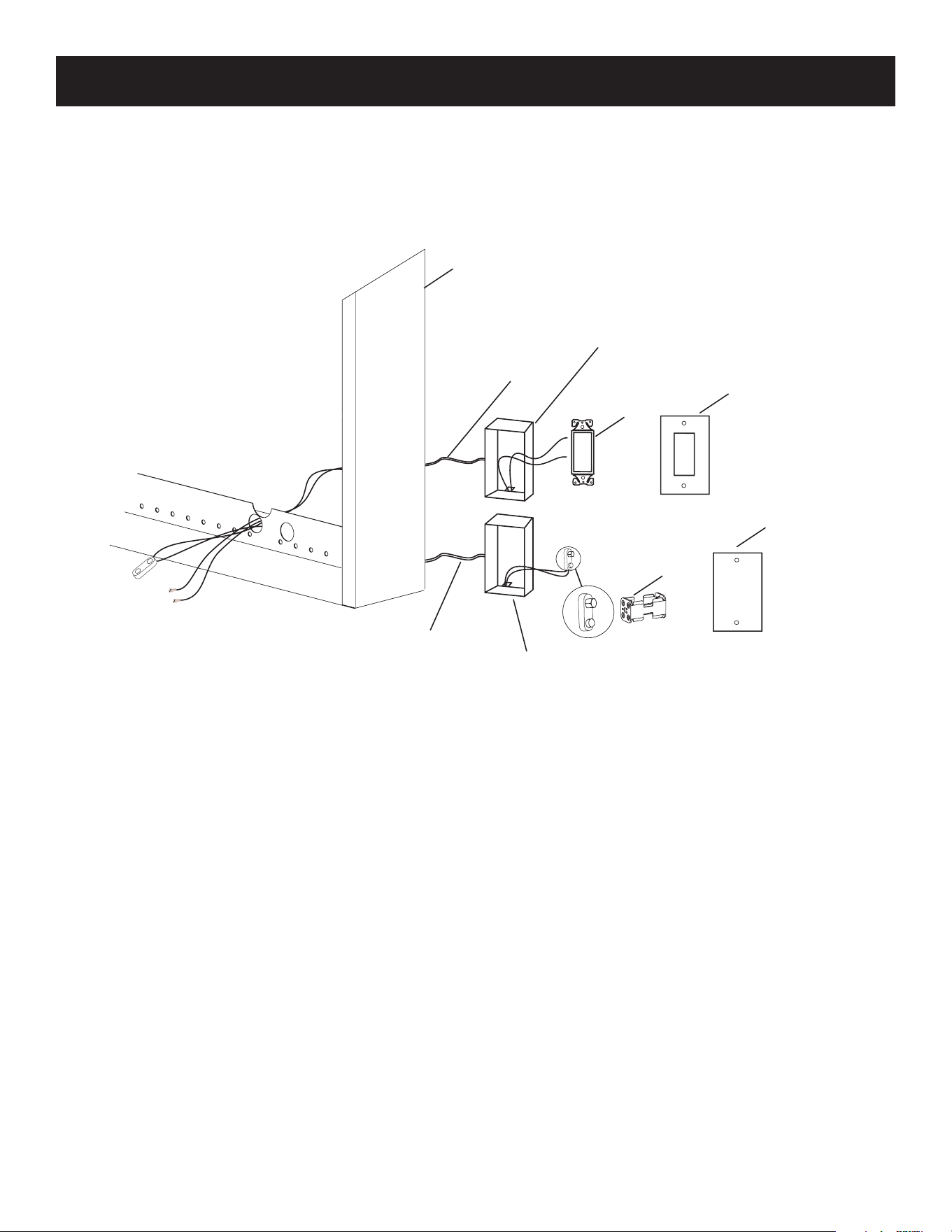
8. Run extension wire harness(es) from opening to junction
box(es)(notprovided)outsideofthereplace.Onejunction
box is for the switch (or other control). The other junction box
isforthebatterypackandwillrequireacover.Extension
wires are 10-ft in length and must connect to battery pack
using the connector end with side walls. Do not extend wires
beyond the 10 feet provided as this will cause the controls to
malfunction. See Figure 5.
DECORATIVE
WRAP
ON\OFF
SWITCH
BATTERY
PACK
10FT
EXTENSION
WIRE
SWITCH
COVER
JUNCTION BOX
COVER
10FT
EXTENSION
WIRE
EXTERNAL
JUNCTION BOX
EXTERNAL
JUNCTION BOX
Figure 5
35775-0-0915Page 20
SURFACE MOUNTED FIREPLACE INSTALLATION
Step 2: Prepare Fireplace
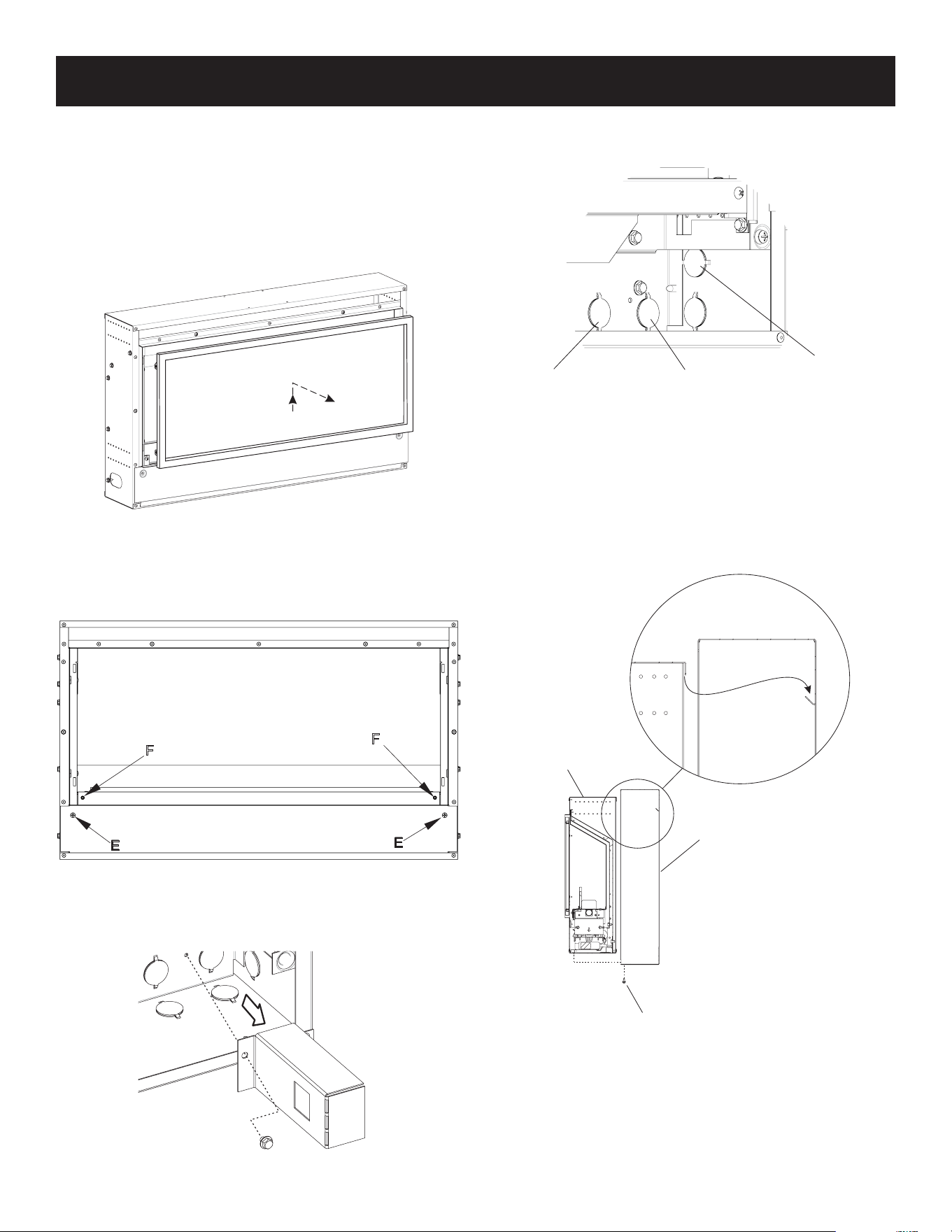
1. Remove the screw securing the standoff on top of the
replace.Discardboththescrewandthestandoff;theyare
not used in this installation.
2. The glass panel is wrapped in cardboard and shipped in the
spaceabovethereplaceopening.Locateglasspanel,and
set aside in a safe location.
3. Remove screen by lifting slightly and pulling out. Remove
contents above burner assembly. See Figure 6.
Figure 6
4. Removescrewsat"E".Removethebottompanelbylifting
and set aside in a safe location. See Figure 7.
5. Removescrewsat"F".Removeburnerassemblyandset
aside in a safe location. See Figure 7.
E
F
F
E
Figure 7
6. Remove junction box on right by removing the screw
securingittothereplace.See Figure 8.
Figure 8
7. Removetheknockoutsinthebackofthereplaceonly.If
using battery pack inside of decorative wrapper, open top
knockoutonthesideofthereplace.See Figure 9.
REMOVE KNOCKOUT
FOR LOW
-VOLTAGE WIRING
REMOVE KNOCKOUT
FOR 120V WIRING
REMOVE KNOCKOUT
FOR BATTERYPACK
IF LOCATED INSIDE
DECORATIVE WRAP
Figure 9
8. Locate snap-in receptacle and snap into junction box.
9. Wire the junction box. See Figure 66, page 50.
Step 3: Install the Fireplace
1. Liftreplaceandhooktoplipontowrapperhook.Let
replacebottomswingintowrap.Carefullyadjustany
wiringthatmaygetintothepathofthereplacethroughthe
corresponding hole. See Figure 10.
FIREPLACE
DECORATIVE
WRAP
TRUSS
HEAD
SCREWS
Figure 10
2. Insert two truss-head screws (provided with the decorative
wrap kit) through the bottom of the decorative wrap and into
thebottomofthereplace.
3. Connecttheexlinetothegasline.
35775-0-0915 Page 21
SURFACE MOUNTED FIREPLACE INSTALLATION
4. Connect battery pack extension wire to connection inside
replace.
5. Connectthegreenandwhitewiresinreplacetothecontrol
extensionwires.Snapcordgripinsideofreplace.
6. Place cord grip around both extension wire harnesses.
7. Run control extension wire to external junction box.
8. Run battery pack wiring to either external junction box or to
location inside decorative wrap.
9. Run120Vpowerlinetoreplace.Placeasnap-incordgrip
over the 120V power line to receptacle in internal junction
box.Snapcordgripinsideofreplace.Usewirenutstojoin
120V power line. See Figure 66, page 50. Re-attach internal
junctionboxinsidereplacethatwasremovedearlierinthe
installation.
10. Plug power adaptor into receptacle in internal junction box.
Connect Power Adaptor terminal into its receiver on the right
of the burner assembly. See Figure 11.
AC POWER ADAPTER
TERMINAL
Figure 11
11. Insert four AA batteries to the battery pack. Place battery
pack inside external junction box (or inside the decorative
wrap) and attach cover.
12. Connect On/Off switch (or optional control) to wiring, connect
extension wire harness and battery pack in external junction
box and attach switch (or optional control) to junction box.
See IP Wiring on page 49 for wiring optional control to green
andwhitewiresinreplace.
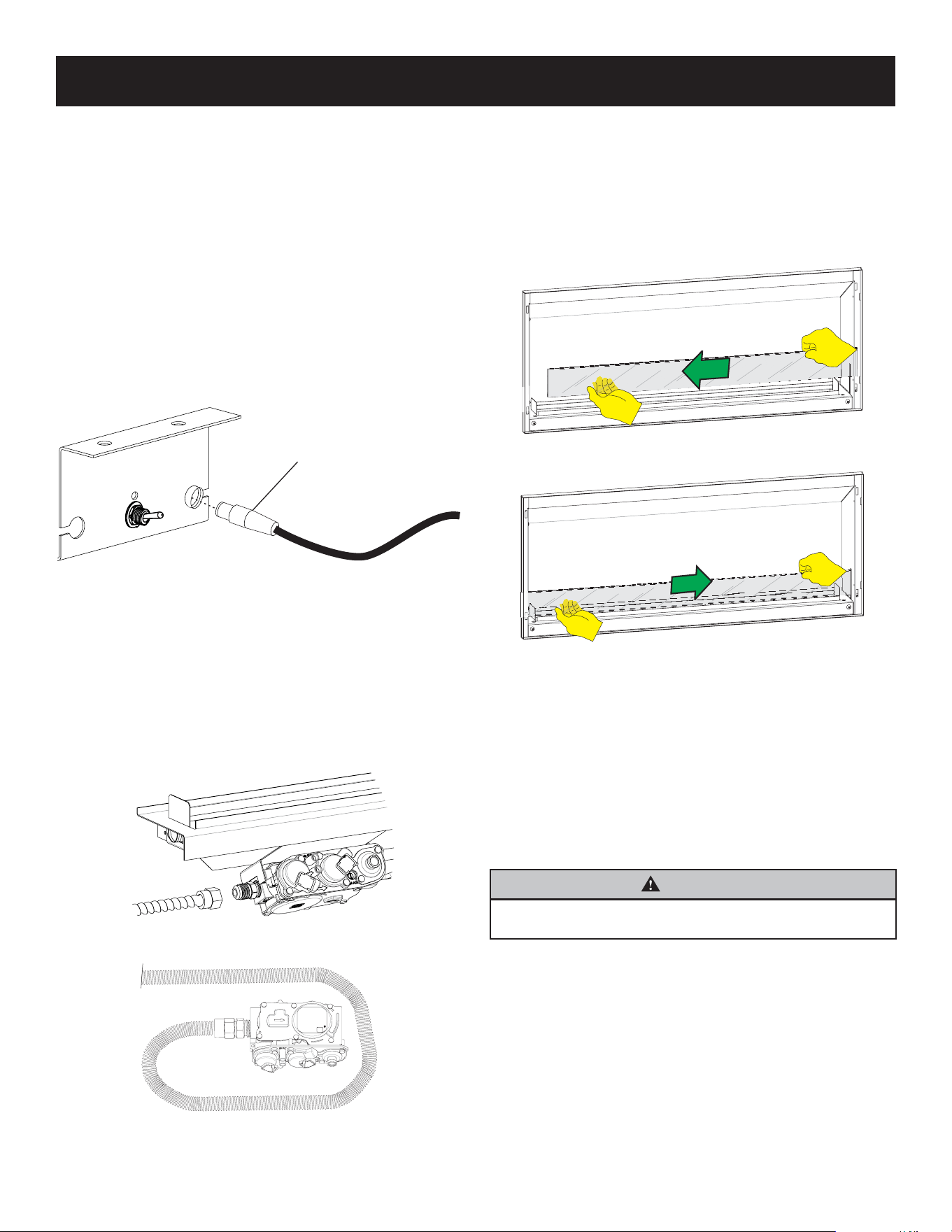
13. Connectgasexlinetoburnerassembly.See Figures 12
and 13 forroutingtheexline.
Figure 12
TOP VIEW
Figure 13
14. Turn gas on and test for leaks at gas inlet.
15. Placeburnerassemblyinsidereplaceandreplacethetwo
truss-headscrews("F"inFigure 7).
16. Verify desired pilot selector switch position. See page 48.
17. Install glass panel in front of burner as shown in Figures 14
and 15.Placeoneendintoslotinsidethereplaceasshown
in Figure 14.Moveotherendofglassintoreplaceopening
andintoslotonothersideofreplace.Moveglasspanel
from side to side until it falls in place.
Figure 14
Figure 15
18. If using optional remote, follow the procedures in the remote
instructions to enable receiver and remote to communicate.
19. Turn on the burner. See Lighting Instructions, Page 46.
20. Testforleaks.Turnreplaceoff.Compoundsusedon
threaded joints of gas piping shall be resistant to the action
ofliqueedpetroleumgases.Thegaslinesmustbechecked
for leaks by the installer. Testing for leaks on all exposed
connections should be done with leak test solution or a
soap solution. After testing is complete, all solution should
be cleaned off. On unexposed connections, a pressure test
should be made.
WARNING
Neveruseanexposedametocheckforleaks.SeeGas
Supply on page 42.
21. Ensure the wire harness is away from the front of the
replaceandnotincontactwithscrewsorsharpedges.
22. Replace bottom panel and re-insert two black, truss-head
screws("E"in Figure 7).
23. Replace screen making certain all four clips catch in
replaceslots.
35775-0-0915Page 22
SURFACE MOUNTED FIREPLACE INSTALLATION
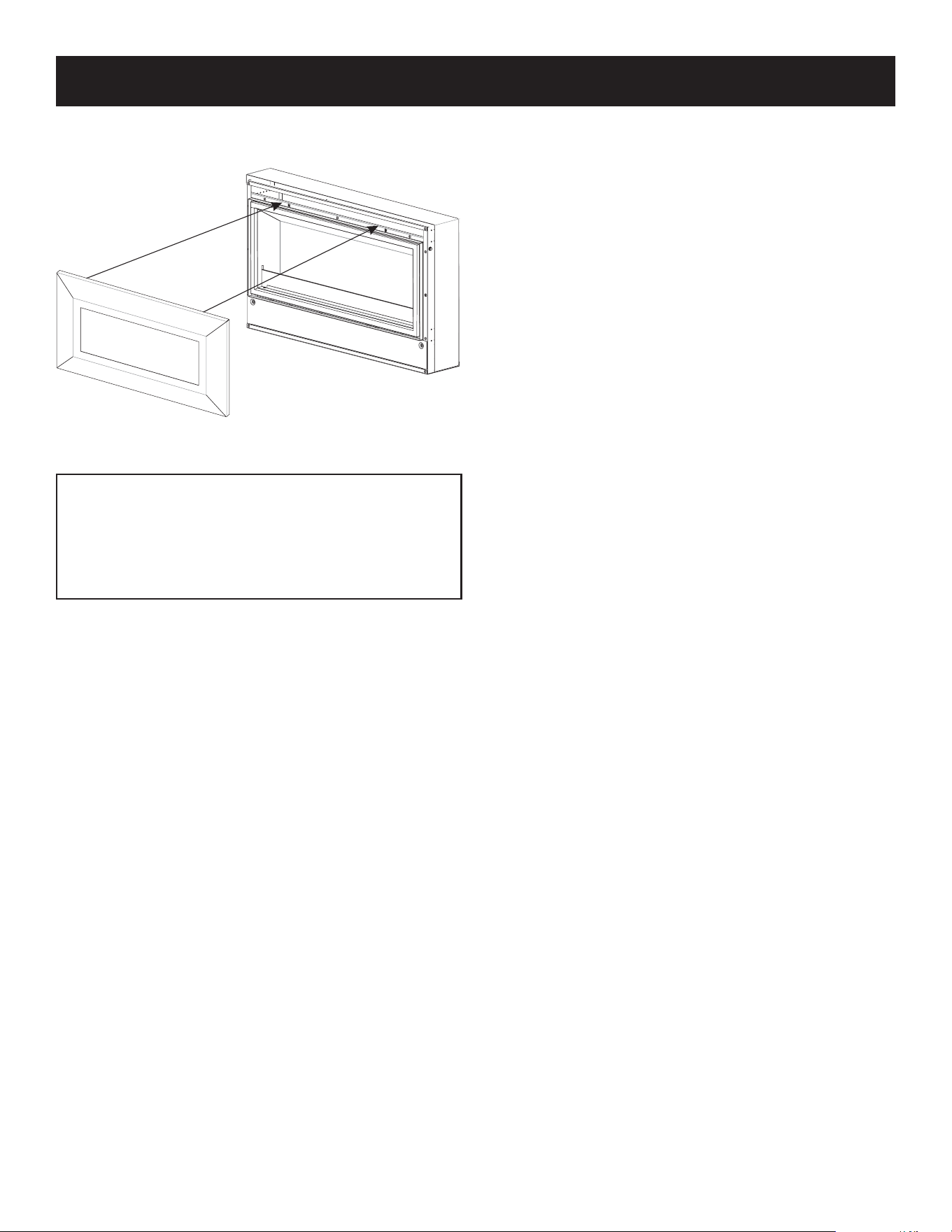
24. Install decorative front by inserting hook on the front above
thetopopeninginthereplace.Verifythatthedecorative
front is level and fully seated. See Figure 16.
Note: Miter Decorative Front Shown
Figure 16
Notice for Finishing with Paint
Use a coating designed for 300°F environments and follow the
manufacturer's instructions for surface preparation, application
andcuring.Heatfromthereplacemaycauseincorrectly
applied coatings to fail or discolor. Light colors may show
some discoloration. Contact paint manufacturer for application
questions.
35775-0-0915 Page 23
PARTIALLY RECESSED FIREPLACE
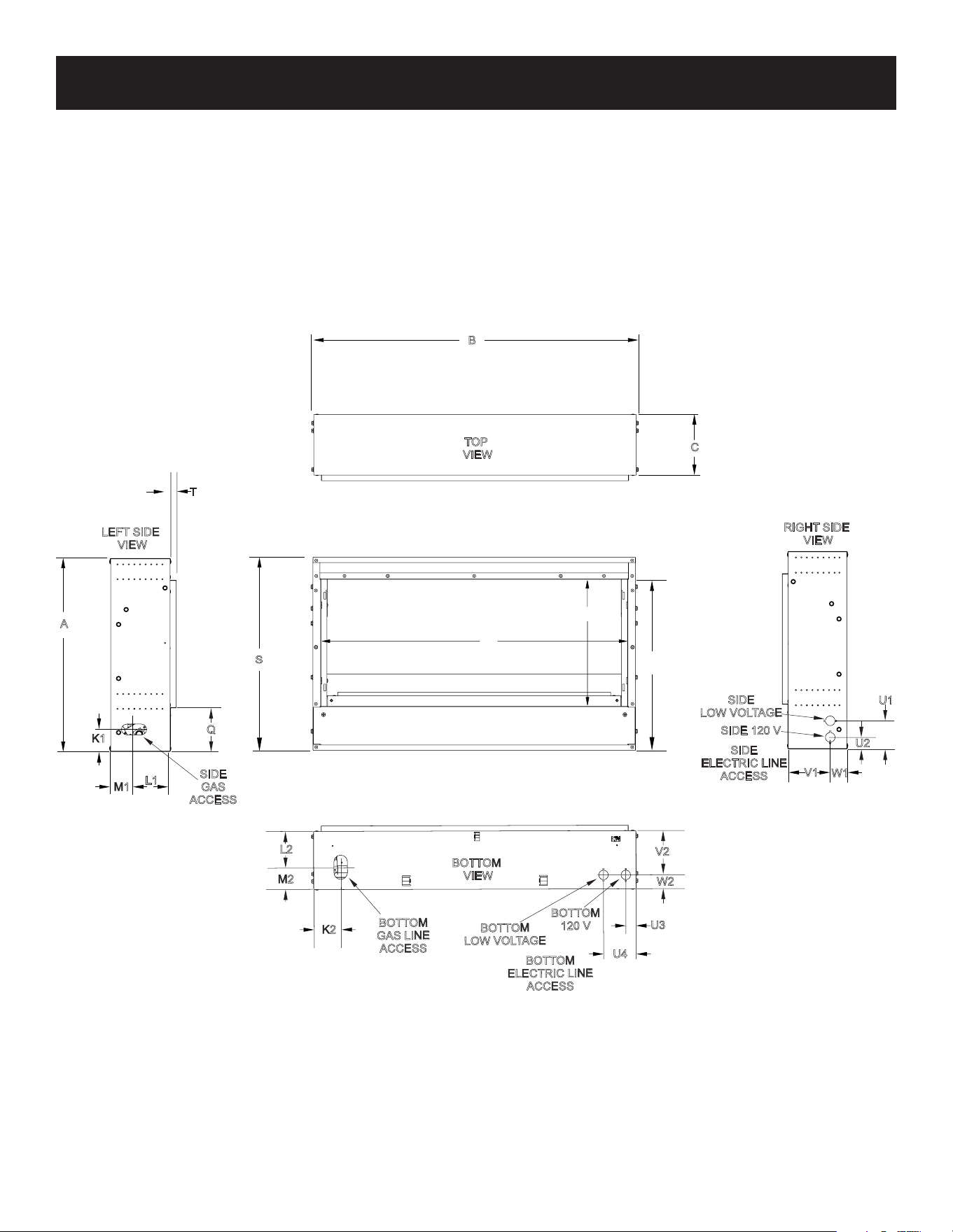
35775-0-0915Page 24
PARTIALLY RECESSED FIREPLACE DIMENSIONS
S
E
D
A
K1
M1
L1
Q
T
SIDE
ELECTRIC LINE
ACCESS
SIDE
LOW VOLTAGE
SIDE 120 V
U1
U2
V1
W1
C
B
TOP
VIEW
RIGHT SIDE
VIEW
BOTTOM
GAS LINE
ACCESS
V2
W2
U3
M2
L2
K2
LEFT SIDE
VIEW
BOTTOM
VIEW
Y
SIDE
GAS
ACCESS
U4
BOTTOM
120 V
BOTTOM
ELECTRIC LINE
ACCESS
BOTTOM
LOW VOLTAGE

35775-0-0915 Page 25
INDEX
LETTER
DIMENSION DESCRIPTION DIMENSIONS
IN INCHES
A Themaximumheightofthereplaceface 17-7/8
B Themaximumwidthofthereplaceface(excludingnailinganges) 30-1/4
C Themaximumdepthofthereplace 5-1/2
D Theheightofthereplaceopening 11-3/4
E Thewidthofthereplaceopening 28-3/8
F Theinteriordepthofthereplace(notshown) 4-3/16
K1 Heightfrombottomofthereplacetothesidegaslineaccess 2-1/16
K2 Distancefromsideofreplacetobottomgaslineaccess 2-11/16
L1 Depthfromfrontofthereplacetosidegaslineaccess 3-5/16
L2 Depthfromfrontofthereplacetobottomgaslineaccess 3-5/16
M1 Depthfromrearofreplacetosidegaslineaccess 2-3/16
M2 Depthfromrearofreplacetobottomgaslineaccess 2-3/16
N Glasspanelheight(notshown)inreplace 2
O Glasspanelwidth(notshown)inreplace 27-1/2
Q Distancefromreplacebottomtoreplaceaccess 4-1/16
S Overall height to top plate 17-7/8
T Openinglipofreplace 9/16
U1 Height to side low voltage electrical line access 2-1/2
U2 Height to side 120V electrical line access 1-1/16
U3 Distancefromsideofreplaceto120Vaccessonbottom 1-1/8
U4 Distancefromsideofreplacetolowvoltageaccessonbottom 3-3/16
V1 Depthfromfrontofreplacetosideelectricallineaccess 3-7/8
V2 Depthfromfrontofreplacetobottomelectricallineaccess 4-3/16
W1 Depthfromrearofreplacetosideelectricallineaccess 1-5/8
W2 Depthfromrearofreplacetobottomelectricallineaccess 1-1/4
Y Distancefrombottomofreplacetotopofopening 15-7/8
PARTIALLY RECESSED FIREPLACE DIMENSIONS
35775-0-0915Page 26
PARTIALLY RECESSED FIREPLACE INSTALLATION
Provided Materials:
Fireplace
Glass Panel
Battery Pack with 10-ft extension wire
Top Non-Combustible Board
Gas Flexline
ON/OFF Switch with 10-ft extension wire and cover (or other
control accessory - sold separately, contact your Empire Dealer)
Snap-in Receptacle
(4) AA Batteries
AC Power Adaptor
(2) Cord Grip
(2) Wire Nut
(12) 1-1/4 Drywall Screws for non-combustible board and nailing
anges
(8) #10 Hex Screws
(4) Nailing Flange
Required Materials - Not Provided:
Decorative Front (Sold Separately, contact your Empire Dealer)
Shut-off valve
(2) Electrical junction boxes (external)
120V wire
Gas piping
Junction Box Cover (for battery pack)
Paper Drywall Tape
Fast-set Drywall Joint Compound
Finish Mud
Tools Needed:
Level
Drill/Phillips Screwdriver
Wrenches
LeakDetectionLiquid
Tape Measure
DANGER
ThisreplacemustbeinstalledbyadealerorcertiedNational
Fireplace Institute technician. A professional will understand
therequirementsforgas,electrical,andframingneedsforthis
installation.
PartiallyRecessedinstallationofthisreplaceinvolvesinstalling
thereplaceintoaframed-inenclosure.A framed-in enclosure
is an enclosure that does not allow drafts through the
rebox from the top, bottom, sides or rear. These drafts
could cause the ame to roll back producing soot or a poor
ame pattern. Follow the framing information in Figure 18.
Thereplaceshouldbeinstalledbyyourdealerorbyacertied
National Fireplace Institute technician. A professional installer
willunderstandthestructuralrequirementsandhaveaccessto
localbuildingcodes.Becauseinstallingthereplacerequires
cutting out one or more studs inside the wall, your installer must
rstdeterminewhetherthewallisloadbearing.Installingthis
replaceinaload-bearingwallwillrequireopeningthewall
beyondthewidthofthereplacetoaddstructuralframingandto
route the gas line and wiring.
Attention: Directions are for non-load bearing walls. For load
bearing walls, consult local codes.
STEP 1: Determine location for replace and prepare
wall.
1. Partiallyrecessedinstallationmeansthatthereplacewill
be both inside the wall and extend from the wall at least
2 inches. An application would be a 2 x 4 framed wall. For a
2x4wall,thereplacewillbeabletogobacktothewall
boardbehindthereplace.Beforeopeningawall,makesure
there are no electrical wires, air ducts, water pipes, cold air
returns,etc.insidethewall.Thisreplacewilltbetweentwo
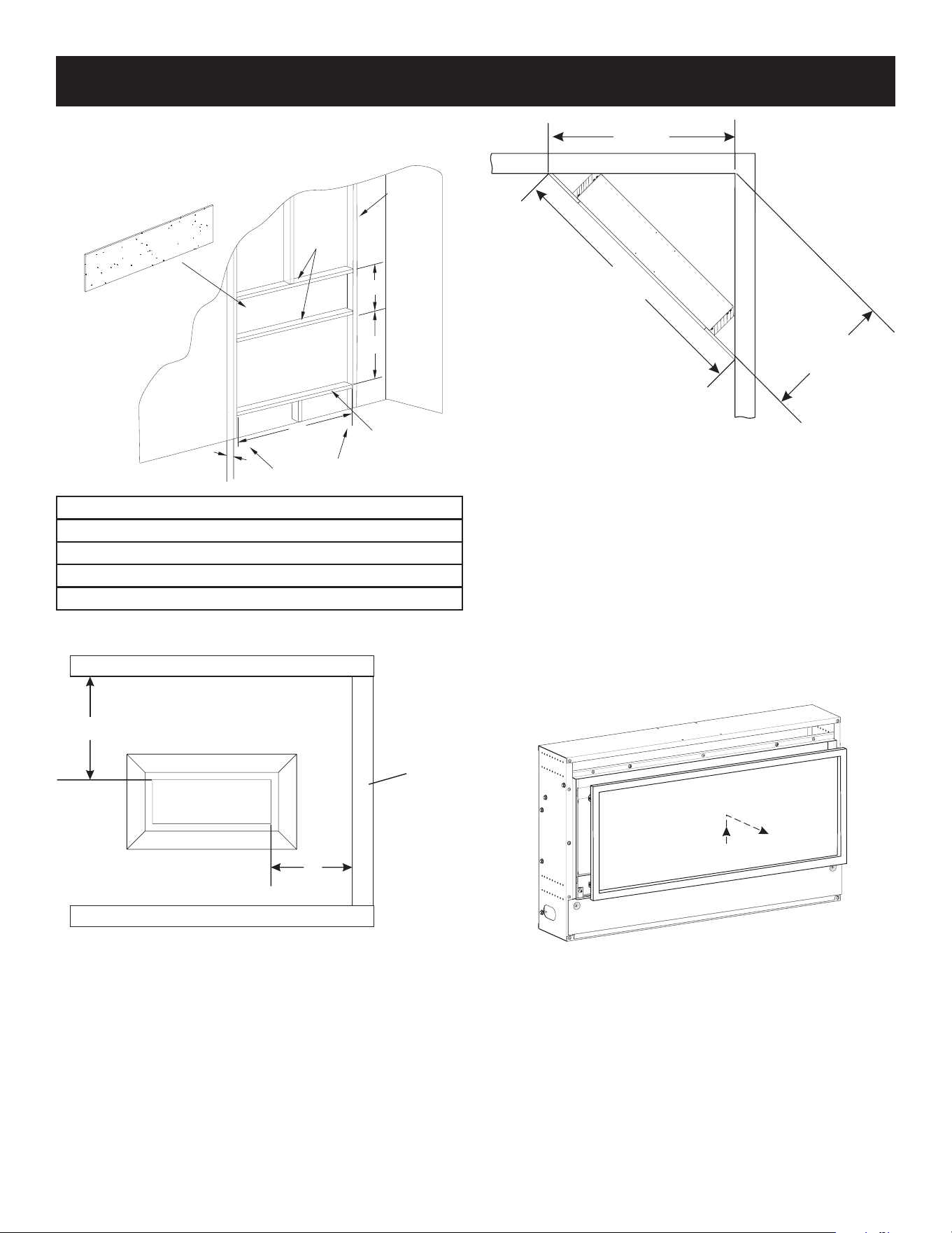
16-inch stud spans. See Figure 18.
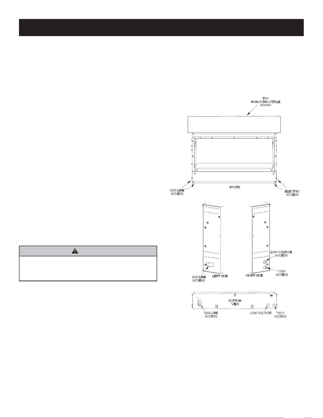
GAS LINE
ACCESS
LEFT SIDE
LOW VOLTAGE
ACCESS
120V
ACCESS
RIGHT SIDE
GAS LINE
ACCESS
ELECTRIC
ACCESS
FRONT
LOW VOLTAGE
120 V
ACCESS
GAS LINE
ACCESS
BOTTOM
VIEW
TOP
NON-COMBUSTIBLE
BOARD
Figure 17
2. See Clearances to Combustibles on pages 43 - 44.
35775-0-0915 Page 27
PARTIALLY RECESSED FIREPLACE INSTALLATION
3. Onceyoudeterminethelocation,andhaveveriedthewall
cavity is free of ducts, pipes, and wires, cut an opening in the
wallforframingthereplace.See Figure 18.
A
B
C
NON-COMBUSTIBLE
BOARD
2 X 4
TOP PLATE
2 X 4
BOTTOM PLATE
2 X 4 STUD
D
GAS
120V
Dimensions (in inches)
A = 3-1/2
B = 30-3/4”
C = 18
D = 14
Figure 18
18” MIN
6”
MIN
CEILING
SIDE WALL
FLOOR
Figure 19 - Ceiling Clearance Illustration
40 3/4
28 3/4
20 3/8
Figure 20 - Corner Clearances Illustration
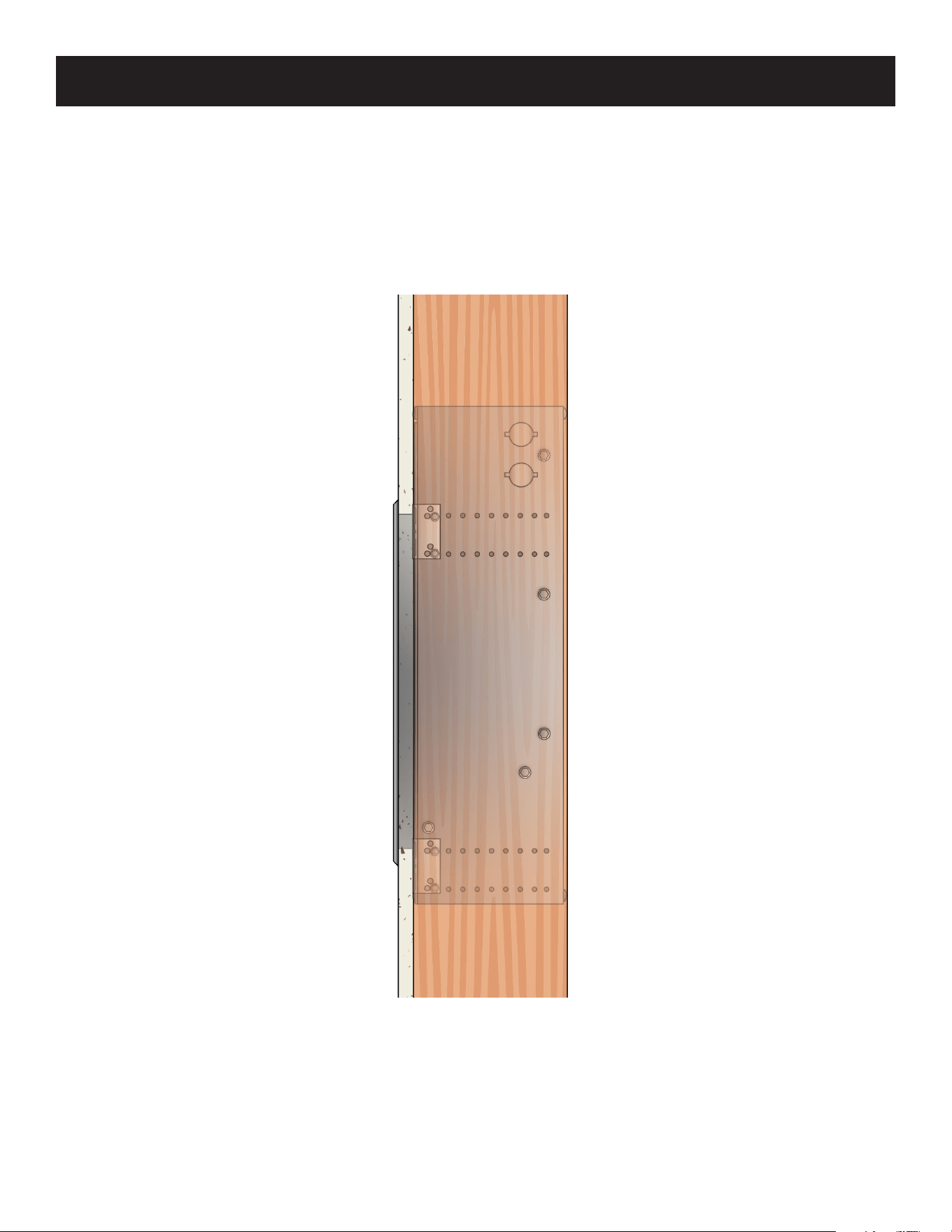
4. Placea2x4topplateoverwherethereplacewillsitanda
2x4bottomplateunderthatwillsupportthereplace.Verify
plates are level.
5. Place a 2 x 4 to support top of non-combustible board.
STEP 2: Prepare the replace
1. Remove the screw securing the standoff on top of the
replace.Discardboththescrewandthestandoff;theyare
not used in this installation type.
2. The glass panel is wrapped in cardboard and shipped in the
spaceabovethereplaceopening.Locateglasspaneland
set aside in a safe location.
3. Remove screen by lifting slightly. Pull screen out. Remove
contents above burner. See Figure 21.
Figure 21
35775-0-0915Page 28
PARTIALLY RECESSED FIREPLACE INSTALLATION
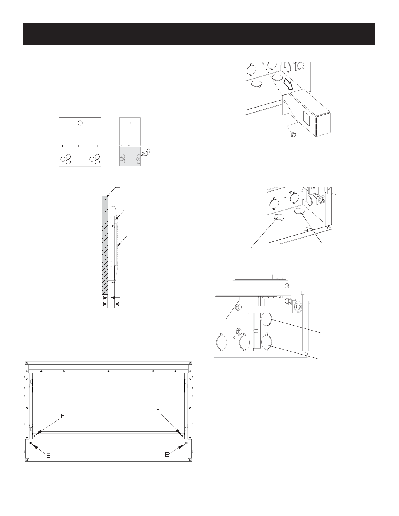
4. Nailingangesareprovided.Bendnailingangestoform
right angles. Locate the pairs of holes on the side of the
replacethatwillallowthefacetobe1-1/2inchesplusthe
thicknessofthenishingmaterial.Forexample,ifusinga
1/2-inch board without tile or other facing material covering
theboard,thedistancefromthefrontofthereplacewill
be 2 inches. If a covering goes over the board, then add 2
inchestothecovering’sthickness.Attachnailingangesto
replaceusinghexscrews.See Figures 22 and 23.
Figure 22
½”
1½”
FINISHED
WALL
FIREPLACE
DECORATIVE
FRONT
FRONT OF
FINISHING MATERIAL
GAP AFTER
COMPLETED
FRONT OF
FIREPLACE
Figure 23
5. Removescrewsat"E".Removethebottompanelbylifting
and set aside in a safe location. See Figure 24.
6. Removescrewsat"F".Removeburnerassemblyandset
aside in a safe location. See Figure 24.
E
F
F
E
Figure 24
7. Remove internal junction box by removing single screw. See
Figure 25.
Figure 25
8. Removetheknockoutrequiredforelectricalinstallation.
See Figure 17, 26 and 27 to determine which knockout that
best meets your needs. Leave other knockouts closed. See
Figures 26 and 27.
KNOCKOUT
FOR BOTTOM ACCESS
OF LOW VOLTAGE
KNOCKOUT FOR BOTTOM
ACCESS
120V WIRING
Figure 26
KNOCKOUT FOR SIDE
ACCESS OF LOW VOLT
AGE
KNOCKOUT FOR SIDE
ACCESS 120V WIRING
Figure 27
9. Locate snap-in receptacle and snap into internal junction
box. See Electrical Considerations, Figure 66, page 50.
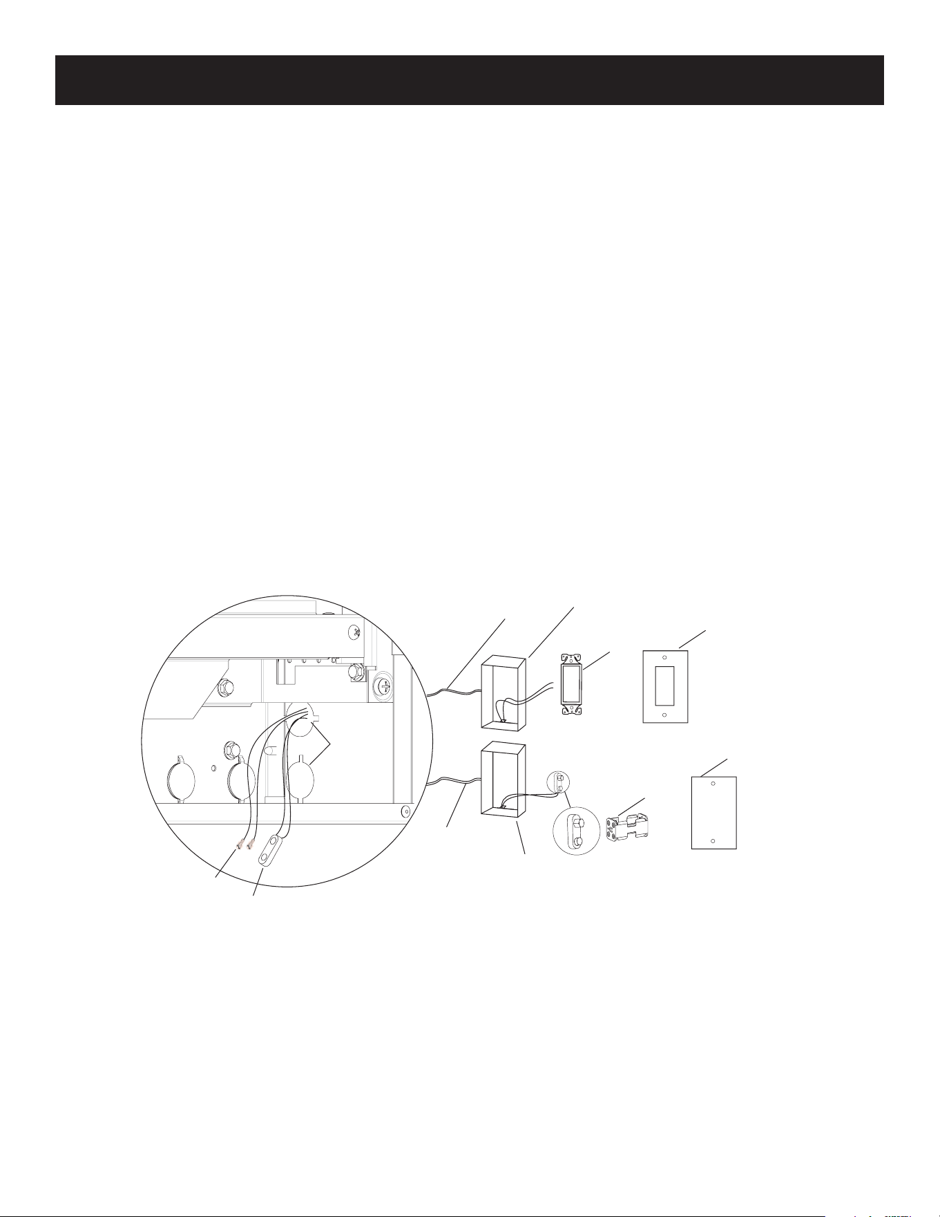
35775-0-0915 Page 29
PARTIALLY RECESSED FIREPLACE INSTALLATION
STEP 3: Install the replace
1. Installreplaceintowall.Securetostudswithfourdrywall
screws.
2. Have the gas tech run gas supply to the desired gas access
location. See Figure 17, Page 26.
3. Have the electrician run the 120V wiring to the 120V access
location. See Figure 17, Page 26.
4. Snap cord grip in place.
5. Wire junction box. See Figure 66, Page 50.
6. Re-attachjunctionboxinsidereplacethatwasremoved
earlier in the installation.
7. Connectexlinetogassupplyline.
8. Run the 10-ft extension wire harness from ON/OFF switch
to the external junction box through low-voltage access in
replace.Connectextensionwirestothegreenandwhite
terminalsinsidethereplace.
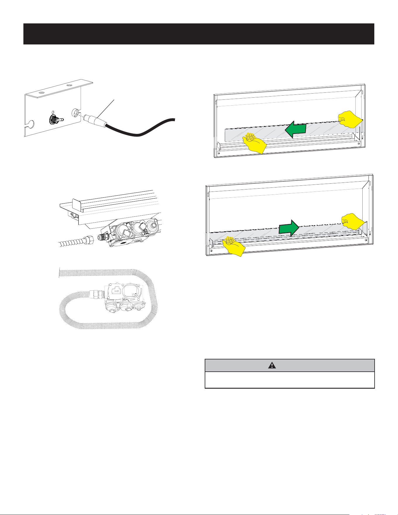
9. Run the 10-ft extension wire from battery pack to the
externaljunctionboxthroughlow-voltageaccessinreplace.
See Figure 28. Connect battery pack extension wire to
terminalsinsidereplace.Snapcordgripsinplacearound
both extension wire harnesses.
10. Connect switch extension wires in external junction box to
On/Off switch (or optional control). See IP Wiring on page
49 for wiring optional control to green and white wires in
replace.Secureswitchandcovertojunctionbox.
11. Place batteries inside battery pack.
12. Connect battery pack to battery pack extension wire in
external junction box. Secure cover to junction box.
OPEN
HOLE
TO BATTERYPACK
TO SWITCH
ON\OFF
SWITCH
BATTERY
PACK
10FT
EXTENSION
WIRE
SWITCH
COVER
JUNCTION BOX
COVER
10FT
EXTENSION
WIRE
EXTERNAL
JUNCTION BOX
EXTERNAL
JUNCTION BOX
Figure 28
Cord grips removed for clairty.
35775-0-0915Page 30
13. Plug power adaptor into plug in junction box on right of
replace.Connectotherendofpoweradaptorterminalinto
its receiver on the right of the burner assembly. See Figure
29.
AC POWER ADAPTER
TERMINAL
Figure 29
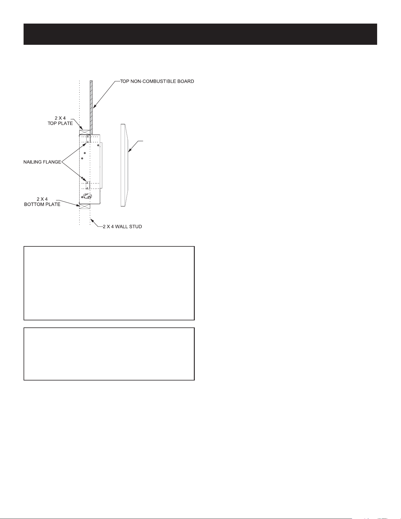
14. Connectgasexlinetoburnerassembly.Wheninstalling
the burner assembly. See Figures 30 and 31 for routing the
exline.Flexlineshouldlooparoundvalvetotheright,tothe
front and back to the valve inlet.
Figure 30
TOP VIEW
Figure 31
15. Turn gas on and test for leaks at gas inlet. Tighten any that
leak.
16. Placeburnerassemblyinsidereplaceandreplacescrews
removedearlier("F"inFigure 24).
17. Verify desired pilot selector switch position. See page 48.
18. Install glass panel in front of burner as shown in Figures 32
and 33.Placeoneendintoslotinsidethereplaceasshown
in Figure 32.Moveotherendofglassintoreplaceopening
andintoslotonothersideofreplace.Moveglasspanel
from side to side until it falls in place.
Figure 32
Figure 33
19. If using optional control, follow procedures in remote
instructions to enable receiver and remote to communicate.
20. Use the switch (or optional remote) to turn on the burner.
See Lighting Instructions, Page 46.
21. Testforleaks.Turnreplaceoff.Compoundsusedon
threaded joints of gas piping shall be resistant to the action
ofliqueedpetroleumgases.Thegaslinesmustbechecked
for leaks by the installer. Testing for leaks on all exposed
connections should be done with leak test solution or a
soap solution. After testing is complete, all solution should
be cleaned off. On unexposed connections, a pressure test
should be made.
WARNING
Neveruseanexposedametocheckforleaks.SeeGas
Supply on page 42.
22. Ensure the wire harness is away from the front of the
replaceandnotincontactwithscrewsorsharpedges.
23. Replace bottom panel and re-insert two black, truss-head
screws("E"inFigure 24).
24. Attachtopnon-combustibleboardabovethereplacewith
drywall screws.
Attention: Allow recommended cure times for mud, tile, paint,
etc.Donotburnreplaceduringthiscuretime.
25. Replace screen making certain all four clips catch in the
replace.
PARTIALLY RECESSED FIREPLACE INSTALLATION
35775-0-0915 Page 31
PARTIALLY RECESSED FIREPLACE INSTALLATION
26. Install decorative front by inserting hook on the front above
thetopopeninginthereplace.Verifythatthedecorative
front is level and fully seated. See Figure 34.
DECORATIVE FRONT
(REQUIRED TO
PURCHASE SEPARATELY)
(MITER DECORATIVE
FRONT SHOWN)
Figure 34
Notice for Finishing with Tile or Stone
Thewallabovethereplacewillbecomehot.Installthe
non-combustibleboardsuppliedwiththereplace.Tileor
other non-combustible materials can be applied to the board
surroundingthereplace.Alladhesivesmustbedesigned
for high-temperature applications (minimum rating of 300°F).
Follow the manufacturer's instructions for application and
curing times. See step 2, # 4 (page 28) for correct placement
ofthenailinganges.Heatfromthereplacemaycause
incorrectly installed materials to fail.
Notice for Finishing with Paint
Use a coating designed for 300°F environments and follow the
manufacturer's instructions for surface preparation, application
andcuring.Heatfromthereplacemaycauseincorrectly
applied coatings to fail or discolor. Light colors may show
some discoloration. Contact paint manufacturer for application
questions.
Non-combustible Board Requirements
1. Donotattachnon-combustibleboardtothereplace.Attach
non-combustible board only to studs and top plate board.
2. Predrill holes into non-combustible board and counter-sink
before installing screws.
3. Use only high-temperature adhesive and high-temperature
paints with the non-combustible board (rating of 300°F or
higher).

35775-0-0915Page 32
This page intentionally blank.
35775-0-0915 Page 33
RECESSED FIREPLACE
35775-0-0915Page 34
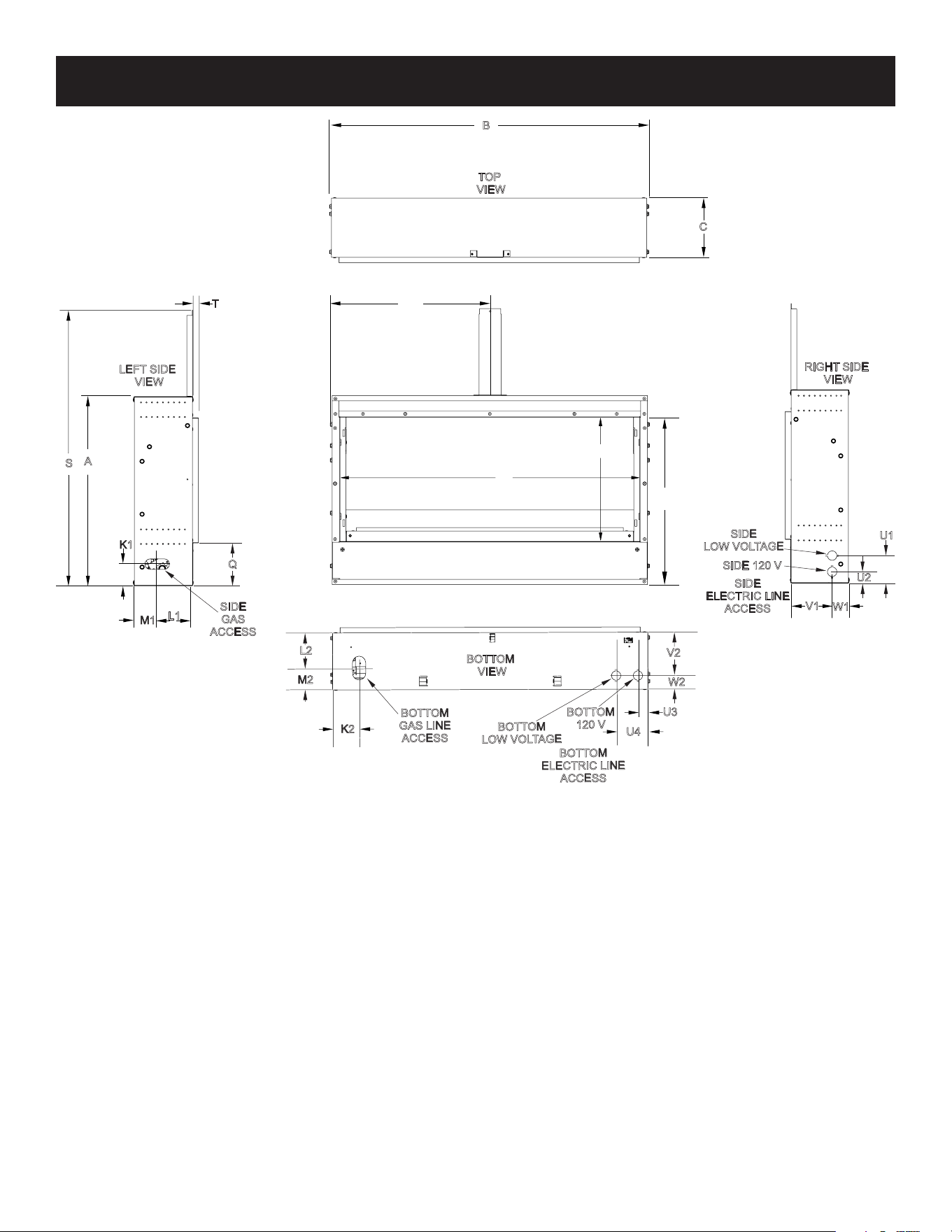
RECESSED FIREPLACE DIMENSIONS
C
B
E
D
A
K1
M1
L1
Q
T
S
U1
U2
V1
W1
TOP
VIEW
RIGHT SIDE
VIEW
LEFT SIDE
VIEW
BOTTOM
120 V
V2
W2
U3
M2
L2
K2
BOTTOM
VIEW
X
Y
SIDE
ELECTRIC LINE
ACCESS
SIDE
LOW VOLTAGE
SIDE 120 V
BOTTOM
ELECTRIC LINE
ACCESS
BOTTOM
LOW VOLTAGE
BOTTOM
GAS LINE
ACCESS
SIDE
GAS
ACCESS
U4

35775-0-0915 Page 35
INDEX
LETTER
DIMENSION DESCRIPTION DIMENSIONS
(IN INCHES)
A Themaximumheightofreplaceface(excludingstandoffs) 17-7/8
B Themaximumwidthofthereplaceface(excludingnailinganges) 30-1/4
C Themaximumdepthofthereplace 5-1/2
D Theheightofthereplaceopening 11-3/4
E Thewidthofthereplaceopening 28-3/8
F Theinteriordepthofthereplace(notshown) 4-3/16
K1 Heightfrombottomofthereplacetothesidegaslineaccess 2-1/16
K2 Distancefromsideofreplacetobottomgaslineaccess 2-11/16
L1 Depthfromfrontofthereplacetosidegaslineaccess 3-5/16
L2 Depthfromfrontofthereplacetobottomgaslineaccess 3-5/16
M1 Depthfromrearofreplacetosidegaslineaccess 2-3/16
M2 Depthfromrearofreplacetobottomgaslineaccess 2-3/16
N Glasspanelheightinreplace(notshown) 2
O Glasspanelwidthinreplace(notshown) 27-1/2
Q Distancefromreplacebottomtoreplaceopening 4-1/16
S Overall height to top plate 29-1/8
T Openinglipofreplace 9/16
U1 Height to side low voltage electrical line access 2-1/2
U2 Height to side 120V electrical line access 1-1/16
U3 Distancefrombottomofreplaceto120Vaccess 1-1/8
U4 Distancefrombottomofreplacetolowvoltageaccess 3-3/16
V1 Depthfromfrontofreplacetosideelectricallineaccess 3-7/8
V2 Depthfromfrontofreplacetopoweraccess 4-3/16
W1 Depthfromrearofreplacetosideelectricallineaccess 1-5/8
W2 Depthfromrearofreplacetopoweraccess 1-1/4
X Sideofreplacetocenterofreplace 15-1/8
Y Distancefrombottomofreplacetotopofopening 15-7/8
RECESSED FIREPLACE DIMENSIONS
35775-0-0915Page 36
RECESSED FIREPLACE INSTALLATION
Provided Materials:
Fireplace
Glass Panel
(2) Side Non-Combustible Board
Top Non-Combustible Board
(4) AA Batteries
(2) Cord Grip
Gas Flexline
Snap-in Receptacle
(16) 1-1/4 Drywall Screws (for non-combustible board and nailing
anges)
AC Power Adaptor
(4) Nailing Flanges
(2) Wire Nut
Battery Pack with 10-ft extension wire
(10) #10 screws
ON/OFF Switch with 10-ft extension wire (or other control
accessory - (Sold Separately, contact your Empire Dealer))
Not Provided Required Materials:
Shut-off valve
(2) Single electrical junction boxes
Junction box cover
120V wire
Gas piping
Optional Materials:
Decorative Trim (sold separately)
NOTICE:Noncombustiblenishingmaterialislimitedto1/2inch
to 1 inch when using optional trim.
Tools Needed:
Level
Drill/Phillips Screwdriver
Wrenches
LeakDetectionLiquid
Tape Measure
Paper Drywall Tape
Fast-set Drywall Joint Compound
Finish Mud
DANGER
ThisreplacemustbeinstalledbyadealerorcertiedNational
Fireplace Institute technician. A professional will understand
therequirementsforgas,electrical,andframingneedsforthis
installation.
Built-ininstallationofthisreplaceinvolvesinstallingthereplace
intoaframed-inenclosure.Thismakesthereplacewindowush
with a wall. A framed-in enclosure is an enclosure that does
not allow drafts through the rebox from the top, bottom,
sides, or rear. These drafts could cause the ame to roll
back producing soot or a poor ame pattern.
Forpartiallyandfullyrecessedapplications,thereplaceshould
beinstalledbyyourdealerorbyacertiedNationalFireplace
Institute technician. A professional installer will understand the
structuralrequirementsandhaveaccesstolocalbuildingcodes.
Becauseinstallingthereplacerequirescuttingoutoneormore
studsinsidethewall,yourinstallermustrstdeterminewhether
thewallisloadbearing.Installingthisreplaceinaload-bearing
wallwillrequireopeningthewallbeyondthewidthofthereplace
to add structural framing and to route the gas line and wiring.
Attention: Directions are for non-load bearing walls. For load
bearing walls, consult local codes.
STEP 1: Find location for replace and prepare wall.
1. Recessedinstallationmeansthatthereplacewillbeinside
the wall. An application would be a 2 x 6 wall studs. For a
2x6wall,thereplacewillbeabletogobacktothewall
boardbehindthereplace.Inselectingalocationbe
cautious of electrical wires, air ducts, water pipes, cold air
returns,etc.thatmayalsobeinsidethewall.Thisreplace
willtbetweentwo16-inchstudspans.See Figure 36.
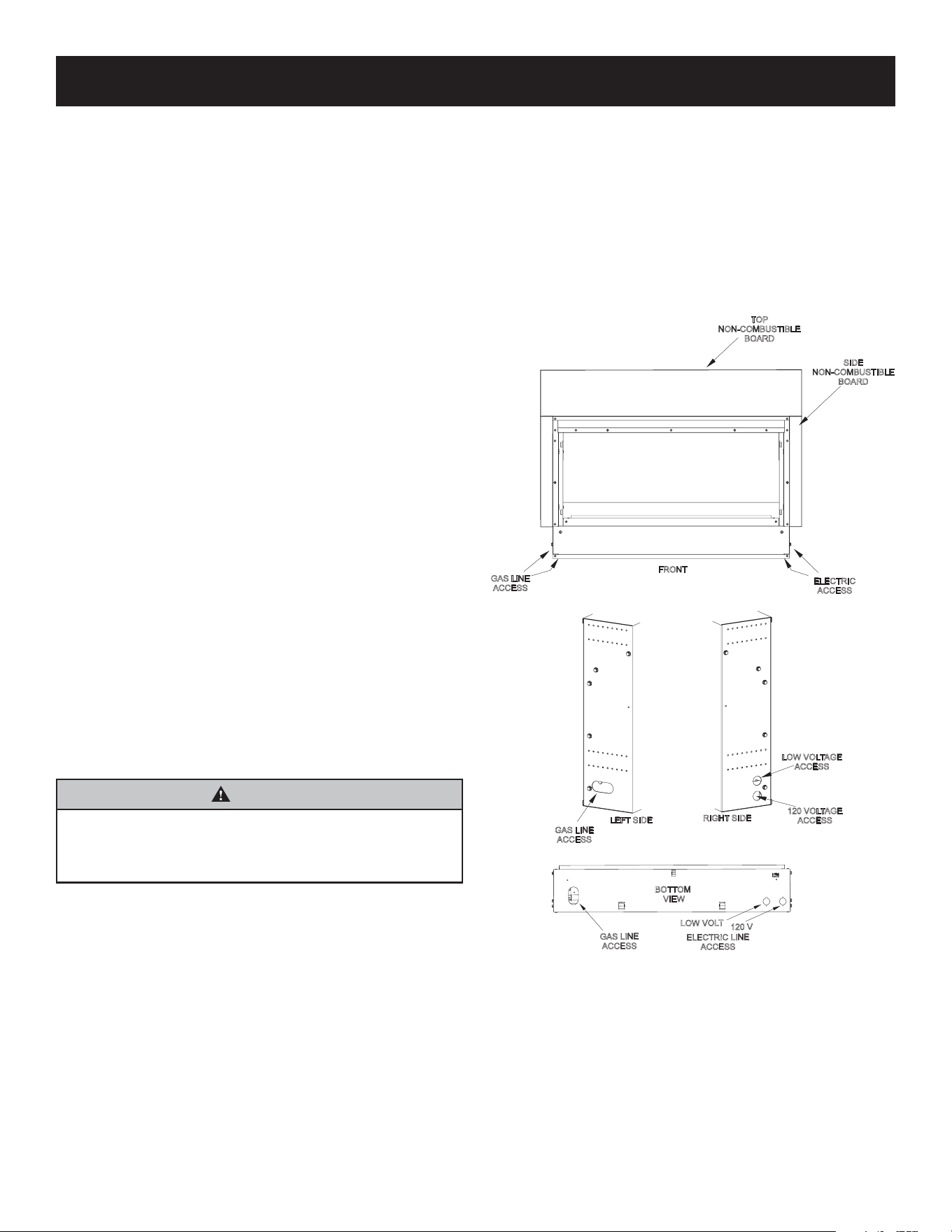
GAS LINE
ACCESS
LEFT SIDE
LOW VOLTAGE
ACCESS
120 VOLTAGE
ACCESS
RIGHT SIDE
GAS LINE
ACCESS
ELECTRIC
ACCESS
FRONT
TOP
NON-COMBUSTIBLE
BOARD
SIDE
NON-COMBUSTIBLE
BOARD
ELECTRIC LINE
ACCESS
LOW VOLT
120 V
GAS LINE
ACCESS
BOTTOM
VIEW
Figure 35
35775-0-0915 Page 37
RECESSED FIREPLACE INSTALLATION
2. See Clearances to Combustibles on pages 43 - 44.
3. Onceyoudeterminethelocation,andhaveveriedthewall
cavity is free of ducts, pipes, and wires, cut an opening in the
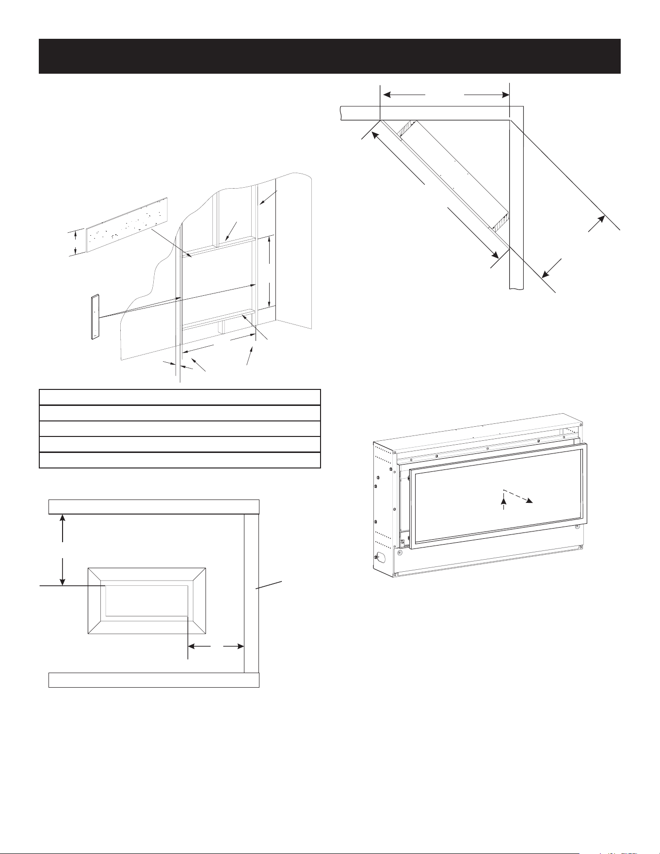
wallforframingthereplace.See Figure 36.
4. Theframingmustsupportthereplace.Placea2x6bottom
platethatwillsupportthereplace.Verifytheplateislevel.
5. Place a 2 x 6 top plate that will support the top of the
non-combustible board. Verify the plate is level.
A
B
C
NON-COMBUSTIBLE
BOARD
2 X 6
TOP PLATE
2 X 6
BOTTOM PLATE
2 X 6 STUD
SIDE
NON-COMBUSTIBLE
BOARD
D
GAS
120V
Dimensions (in inches)
A = 5-1/2
B = 30-3/4
C = 29-1/2
D = 14
Figure 36
18” MIN
6”
MIN
CEILING
SIDE WALL
FLOOR
Figure 37 - Ceiling Clearance Illustration
40 3/4
28 3/4
20 3/8
Figure 38 - Corner Clearances Illustration
STEP 2: Prepare replace
1. Remove the screw securing the standoff on top of the
replace.Setthescrewandstandoffasideinasafelocation.
2. The glass panel is wrapped in cardboard and shipped in the
spaceabovethereplaceopening.Locateglasspaneland
set aside in a safe location.
3. Remove screen by lifting slightly. Pull screen out. Remove
contents above burner. See Figure 39.
Figure 39
35775-0-0915Page 38
RECESSED FIREPLACE INSTALLATION
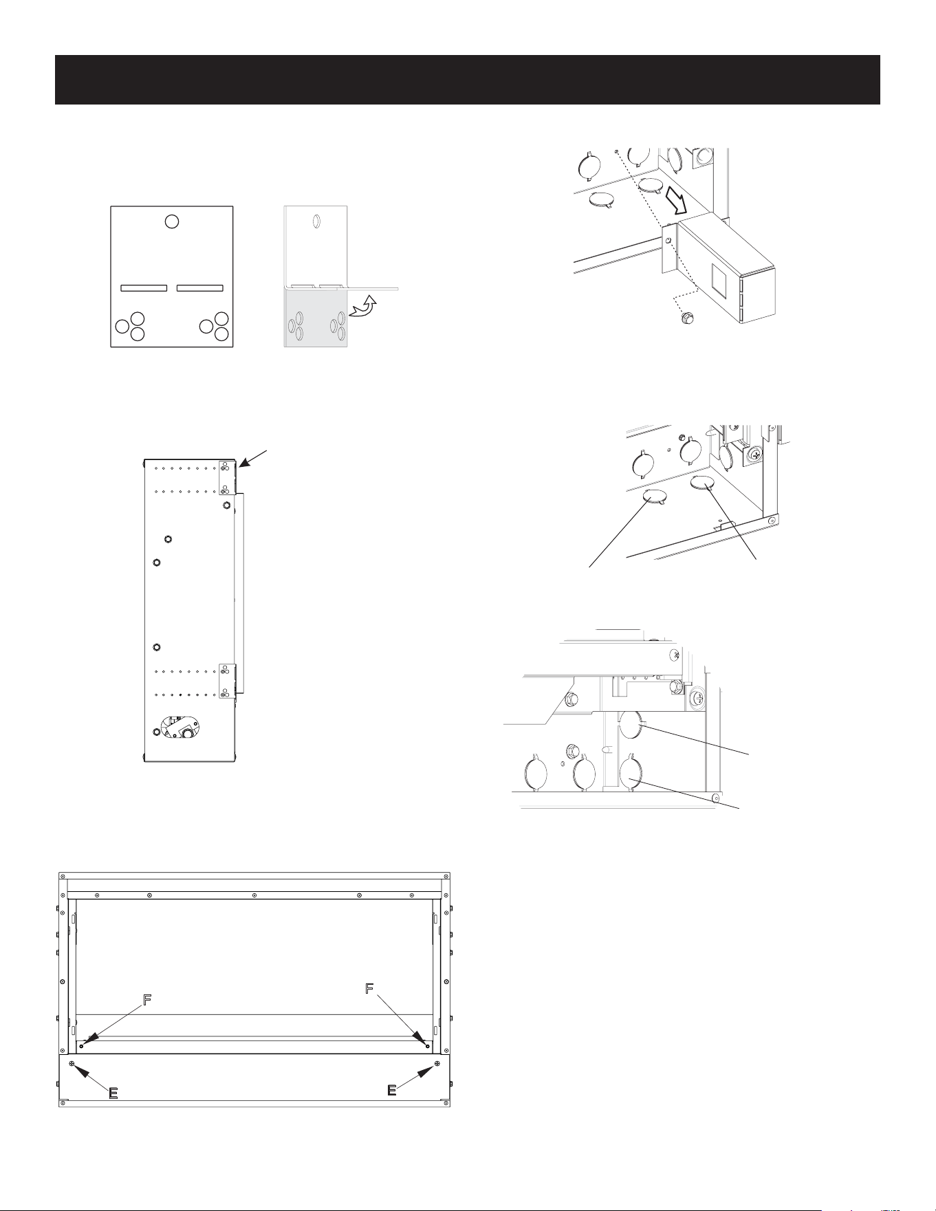
4. Nailingangesareprovided.Theangesincludedareat
but easily bend to form a right angle. Locate the pairs of
holesonthesideofthereplacethatwillplacetheoutsideof
thewallcoveringatthe1/16-inchpastthereplaceopening.
See Figure 40.
Figure 40
5. Screwnailingangesintothereplacewithhexscrews
provided in hardware pack. See Figure 41.
RECESSED POSITON
OF NAILING FLANGE
Figure 41
6. Remove screws at “E”. Remove bottom of face by lifting and
set aside in a safe location. See Figure 42.
7. Remove screws at “F”. Remove burner assembly and set
aside in a safe location. See Figure 42.
E
F
F
E
Figure 42
8. Remove junction box on right by removing single screw. See
Figure 43.
Figure 43
9. Usingbackandforthaction,opentheknockoutsrequiredfor
installation. Leave other knockouts closed. See Figures 44
and 45.
KNOCKOUT
FOR BOTTOM ACCESS
OF LOW VOLTAGE
KNOCKOUT FOR BOTTOM
ACCESS
120V WIRING
Figure 44
KNOCKOUT FOR SIDE
ACCESS OF LOW VOLTAGE
KNOCKOUT FOR SIDE
ACCESS 120V WIRING
Figure 45
10. Locate snap-in receptacle and snap into junction box. Set
aside. See Electrical Considerations - See Figure 66, page
50.
11. Retrievestandoffandinstallontotopofreplacebybending
bottom tabs and attach with #10 hex screws.
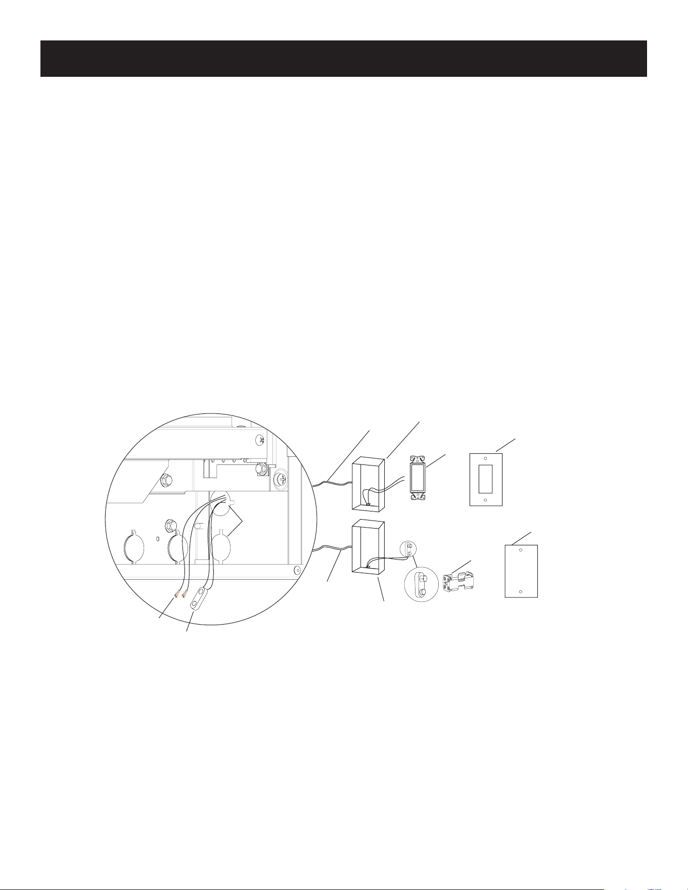
35775-0-0915 Page 39
Figure 46
RECESSED FIREPLACE INSTALLATION
STEP 3: Install the replace
1. Installthereplaceintothecutoutinthewall.Attachtoside
studs with drywall screws. Attach the top standoff to the top
plate with a drywall screw.
2. Have the gas technician run gas supply to the desired gas
access location. See Figure 36, Page 36.
3. Have the electrician run the 120V wiring to the 120V access
location. See Figure 36, Page 36.
4. Connectexlinetogassupplyline.
5. Run the extension wire harnesses from low-voltage access
to the electrical junction boxes (not provided). Extension
wires are 10-feet lengths and must connect to the battery
pack with the connector having side walls. See Figure 46.
6. Run the 10-ft switch extension wires from ON/OFF switch
through low-voltage access to external junction box. Connect
extension wires to the green and white terminals inside the
replace.Placecordgriparoundlow-voltagewiresandsnap
intoreplace.
7. Securebatterypackconnectionwireinsidereplace.
8. Connect extension switch wires in external junction box to
On/Off switch (or optional controls). See IP Wiring on page
49 for wiring optional control to green and white wires in
replace.Secureswitchandcovertoexternaljunctionbox.
9. Place batteries inside battery pack.
10. Connect battery pack to battery pack extension wires in
external junction box. Secure cover to external junction box.
OPEN
HOLE
TO BATTERYPACK
TO SWITCH
ON\OFF
SWITCH
BATTERY
PACK
10FT
EXTENSION
WIRE
SWITCH
COVER
JUNCTION BOX
COVER
10FT
EXTENSION
WIRE
EXTERNAL
JUNCTION BOX
EXTERNAL
JUNCTION BOX
Cord grips removed for clairty.
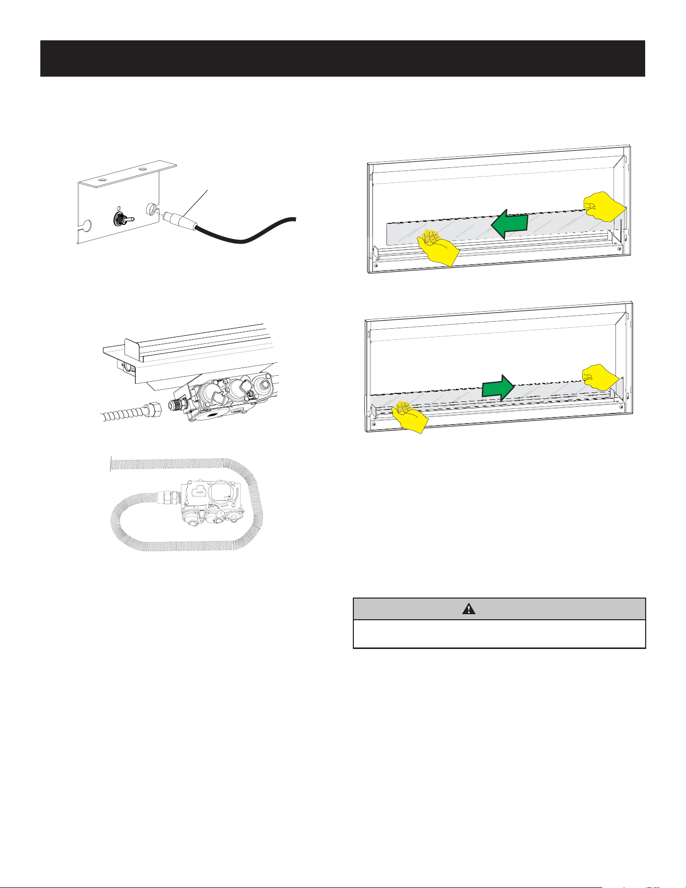
35775-0-0915Page 40
11. Connect the 120V power line to receptacle in internal
junction box. See Figure 66, page 50. Re-attach junction
boxinsideofreplace.
12. Plug power adaptor into receptacle in junction box inside
replace.Connectpoweradaptorterminalintoitsreceiveron
the right of the burner assembly. See Figure 47.
AC POWER ADAPTER
TERMINAL
Figure 47
13. Connectgasexlinetoburnerassembly.Wheninstallingthe
burnerassembly,looptheexlinearoundvalvetotheright,
to the front and back to the valve inlet. See Figures 48 and
49forroutingtheexline.
Figure 48
TOP VIEW
Figure 49
14. Turn gas on and test for leaks. Tighten any connection that
leak.
15. Placeburnerassemblyinsidereplaceandreplacescrews
removedearlier("F"inFigure 42).
16. Verify desired pilot selector switch position. See page 48.
RECESSED FIREPLACE INSTALLATION
17. Install glass panel in front of burner as shown in Figures 50
and 51.Placeoneendintoslotinsidethereplaceasshown
in Figure 50.Moveotherendofglassintoreplaceopening
andintoslotonothersideofreplace.Moveglasspanel
from side to side until it falls in place.
Figure 50
Figure 51
18. If using optional control, follow procedures in remote
instructions to enable receiver and remote to communicate.
19. Use the switch (or optional remote) to turn on the burner.
20. See Lighting Instructions, Page 46. Test for leaks. Turn
replaceoff.Compoundsusedonthreadedjointsofgas
pipingshallberesistanttotheactionofliqueedpetroleum
gases. The gas lines must be checked for leaks by the
installer. Testing for leaks on all exposed connections should
be done with leak test solution or a soap solution. After
testing is complete, all solution should be cleaned off. On
unexposed connections, a pressure test should be made.
WARNING
Neveruseanexposedametocheckforleaks.SeeGas
Supply on page 42.
21. Ensure the wire harness is away from the front of the
replaceandnotincontactwithscrewsorsharpedges.
22. Replace bottom panel and re-insert two black, truss-head
screws("E"inFigure 42).
23. Use drywall screws to attach top non-combustible board
abovereplace.See Figure 36.
24. Use drywall screws to attach side non-combustible board on
eachsideofthereplace.See Figure 36.
Attention: Allow recommended cure times for mud, tile, paint,
etc.Donotoperatereplaceduringthiscuretime.
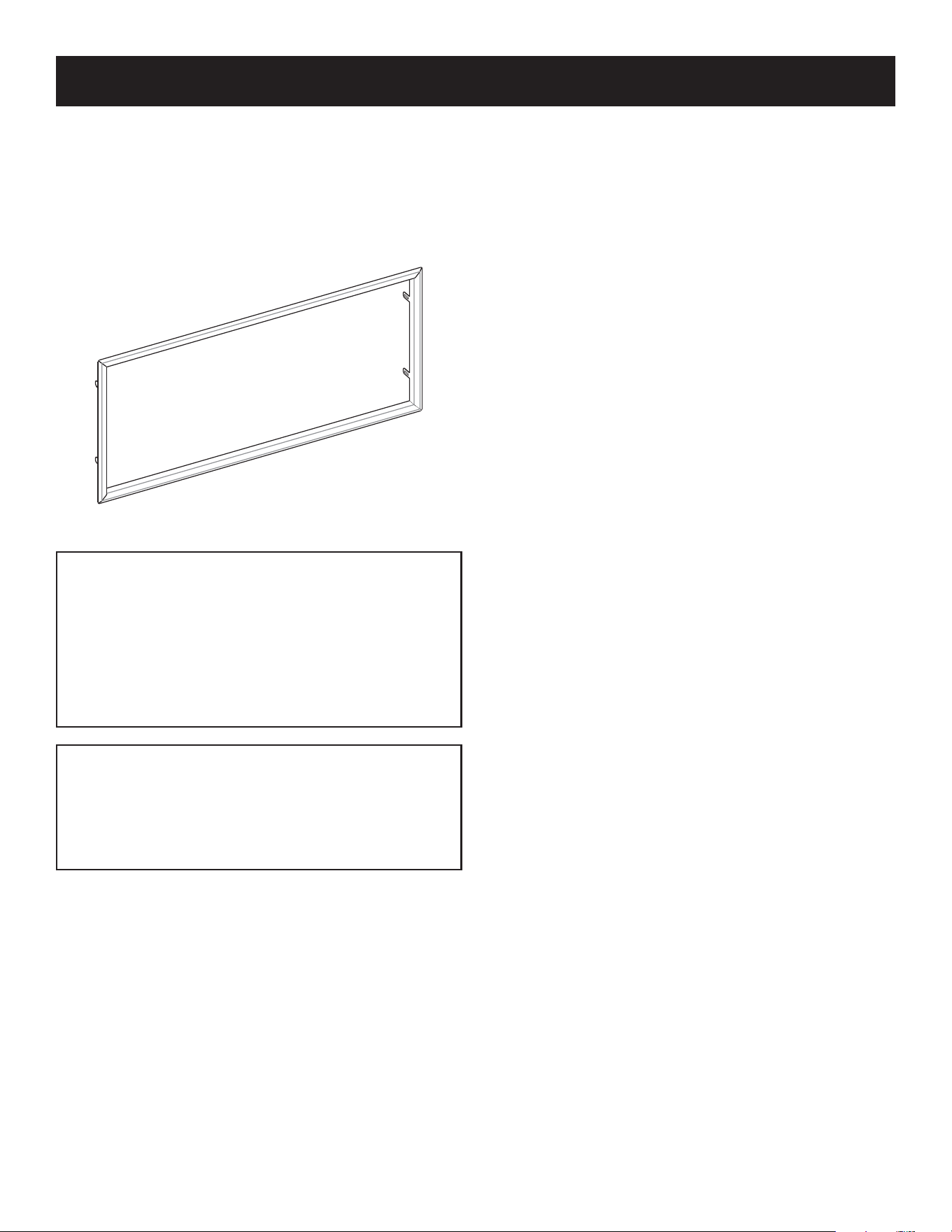
35775-0-0915 Page 41
25. Install optional decorative trim by inserting tabs into the
smallslotstotheleftandrightoftheopeninginthereplace.
Insertscrewfromdecorativetrimkitintosidesofreplace.
Screws will go through slots in the decorative trim tabs.
26. Replace screen making certain all four clips catch in the
replace.
Optional Drywall Trim for Non-Combustible Surface
Installation
Figure 52
Notice for Finishing with Tile or Stone
Thewallabovethereplacewillbecomehot.Installthenon-
combustibleboardsuppliedwiththereplace.Tileorother
non-combustible materials can be applied to the board or face
ofthereplace.Alladhesivesmustbedesignedforhigh-
temperature applications (minimum rating of 300°F). Follow the
manufacturer's instructions for application and curing times.
See step 2, # 4 (page 28) for correct placement of the nailing
anges.Heatfromthereplacemaycauseincorrectlyinstalled
materials to fail.
Notice for Finishing with Paint
Use a coating designed for 300°F environments and follow the
manufacturer's instructions for surface preparation, application
andcuring.Heatfromthereplacemaycauseincorrectly
applied coatings to fail or discolor. Light colors may show
some discoloration. Contact paint manufacturer for application
questions.
Non-combustible Board Requirements
1. Donotattachnon-combustibleboardtothereplace.Attach
non-combustible board only to studs and top plate board.
2. Predrill holes into non-combustible board and counter-sink
before installing screws.
3. Use only high-temperature adhesive and high-temperature
paints with the non-combustible board (adhesive and paints
must have a minimum temperature rating of 300°F).
RECESSED FIREPLACE INSTALLATION
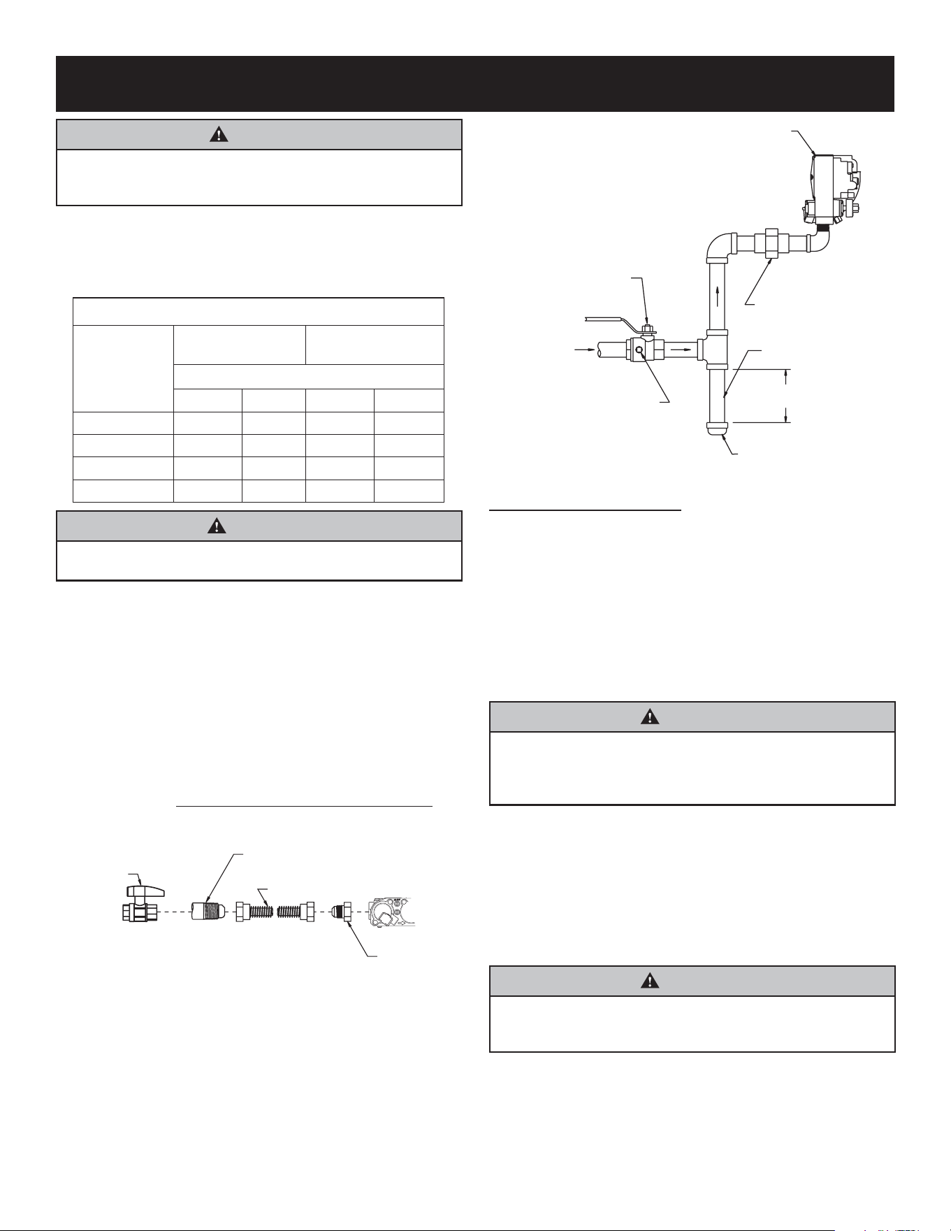
35775-0-0915Page 42
GAS SUPPLY
CAUTION
Two gas line installations at the same time are prohibited. The
access plate to the switching means shall not be opened while
the heater is in operation.
The gas pipeline can be brought in through the left side or
bottomofthereplace.TheinserthasaFlexlinewithshutoff
valve located on the left side or bottom when facing the unit. See
Figure 35. Consult the current National Fuel Gas Code, ANSI
Z223.1 CAN/CGA-B149 (.1 or .2) installation code.
Recommended Gas Pipe Diameter
Pipe Length
(in feet)
Schedule 40 Pipe
Inside Diameter
Tubing, Type L
Outside Diameter
(in inches)
NAT LP NAT LP
0 - 10 1/2 3/8 1/2 3/8
11 - 40 1/2 1/2 5/8 1/2
41 - 100 1/2 1/2 3/4 1/2
101 - 150 3/4 1/2 7/8 3/4
WARNING
Neveruseplasticpipeforgasline.Checktoconrmwhether
your local codes allow copper tubing or galvanized.
NOTICE: Because some municipalities have additional local
codes, it is always best to consult your local authority and
installation code.
The use of the following gas connectors is recommended:
— ANSI Z21.24 Fireplace Connectors of Corrugated Metal
Tubing and Fittings.
— ANSI Z21.45 Assembled Flexible Fireplace Connectors of
Other Than All-Metal Construction
The above connectors may be used if acceptable by the authority
having jurisdiction. The Commonwealth of Massachusetts
requiresthataexiblereplaceconnectorcannotexceed3feet
in length.
TEE HANDLE
FLEX TUBING
FLARE FITTING
FLEXIBLE GAS LINE CONNECTION
GAS SUPPLY
Figure 53
A gas valve and ground joint union should be installed in the gas
lineupstreamofthegascontroltoaidinservicing.Itisrequired
by the National Fuel Gas Code that a drip leg be installed near
the gas inlet. See Figure 54. This should consist of a vertical
length of pipe tee connected into the gas line that is capped
on the bottom in which condensation and foreign particles may
collect.
GAS
VALVE
GAS SUPPLY PIPING
SHUT-OFF VALVE
GAS SUPPLY
INLET
1/8 NPT PLUGGED HOLE
FOR TEST GAGE
3” MINIMUM
GROUND JOINT UNION
DRIP LEG
CAP
Figure 54
Installing the Main Gas Valve
Eachreplaceshouldhaveitsownmanualgasvalvelocatedin
the vicinity of the unit that can be easily accessed after assembly.
Wherenoneexists,orwhereitssizeorlocationisnotadequate,
contact your local authorized installer for installation or relocation.
Compounds used on threaded joints of gas piping shall be
resistanttotheactionofliqueedpetroleumgases.Thegaslines
must be checked for leaks by the installer. Testing for leaks on all
exposed connections should be done with leak test solution or
a soap solution. After testing is complete, all solution should be
cleaned off. On unexposed connections, a pressure test should
be made.
WARNING
Neveruseanexposedametocheckforleaks.Fireplacemust
be disconnected from piping at inlet of control valve and pipe
capped or plugged for pressure test. Never pressure test with
replaceconnected;controlvalvewillsustaindamage!
Whenusingcopperorexconnectoruseonlyapprovedttings.
Thereplaceandit’sindividualshutoffvalvemustbe
disconnected from supply piping system during any pressure
testing of that system at test pressures in excess of 1/2 psig
(3.5kPa).
Thereplacemustbeisolatedfromthegassupplypipingsystem
by closing its individual manual shut off valve during any pressure
testingofthegassupplypipingsystemattestpressuresequalto
or less than 1/2 psig (3.5kPa).
WARNING
If one of the procedures results in pressures in excess of
1/2psig(14inchesw.c.)(3.5kPa)onthereplacegasvalve,it
will result in a hazardous condition.
Shut off valve must be accessible after installation.
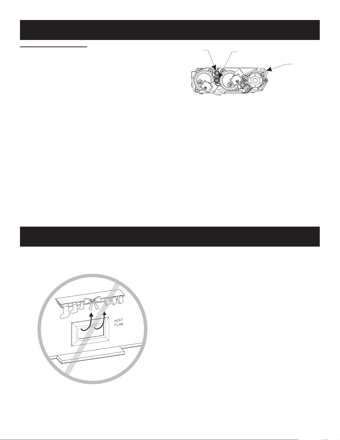
35775-0-0915 Page 43
COMBUSTIBLE MATERIALS
Combustible Material
Do not attach combustible material to the mantel of your
replace.Thisisarehazard.
Figure 55
Usenon-combustiblematerialswhereindicatedforthereplace
installation. Non-combustible materials do not ignite or burn
asaresultofusingthereplace.Theseincludemetal,brick,
ceramic, concrete, slate, glass, and plaster. Adhesives must be
ratedforreplacehightemperatureapplications.Anymechanical
fasteners used to install materials must also be non-combustible,
including wall anchors and tile spacers. Materials that pass
the ASTM E-136 test (Standard Test Method for Behavior of
Materials in a Vertical Tube Furnace at 750C) are considered
non-combustible.
Do not allow combustible materials adjacent to or in contact with
thereplace.Combustiblematerialsincludewood,compressed
paper,plantbers,orothermaterialsthatwillburn.These
materials are considered combustible even when treated with
re-retardantchemicals.
Television Considerations
Installingatelevisionaboveareplacehasbecomeincreasingly
popular;however,theareaaboveanyreplacegetshotandmost
TV manufacturers recommend against placing their products
near a heat source.
Ifyouinstallatelevisionabovethisreplace,EmpireComfort
Systems accepts no responsibility for damage or injuries. Follow
the television manufacturer’s installation instructions, including
any recommendations regarding proximity to heat sources.
IfyouhaveaTVaboveyourreplace,turnoffthereplaceand
let it cool completely before servicing or touching any buttons on
the TV.
GAS SUPPLY
Checking Manifold Pressure
Natural gas will have a manifold pressure of approximately
3.5 inches w.c. at the pressure regulator outlet with the
inlet pressure to the pressure regulator from a minimum of
5.0 inches w.c. for the purpose of input adjustment to a maximum
of 10.5 inches w.c.
Propane gas will have a manifold pressure approximately
10.0 inches w.c. at the pressure regulator outlet with the
inlet pressure to the pressure regulator from a minimum of
11.0 inches w.c. for the purpose of input adjustment to a
maximum of 13.0 inches w.c.
A test gage connection is located downstream of the gas
replacepressureregulatorformeasuringgaspressure.The
connection is a 1/8 inch N.P.T. plugged tapping.
GAS VALV
E
OUTLET
PRESSURE
TA
P
INLET
PRESSURE
TAP
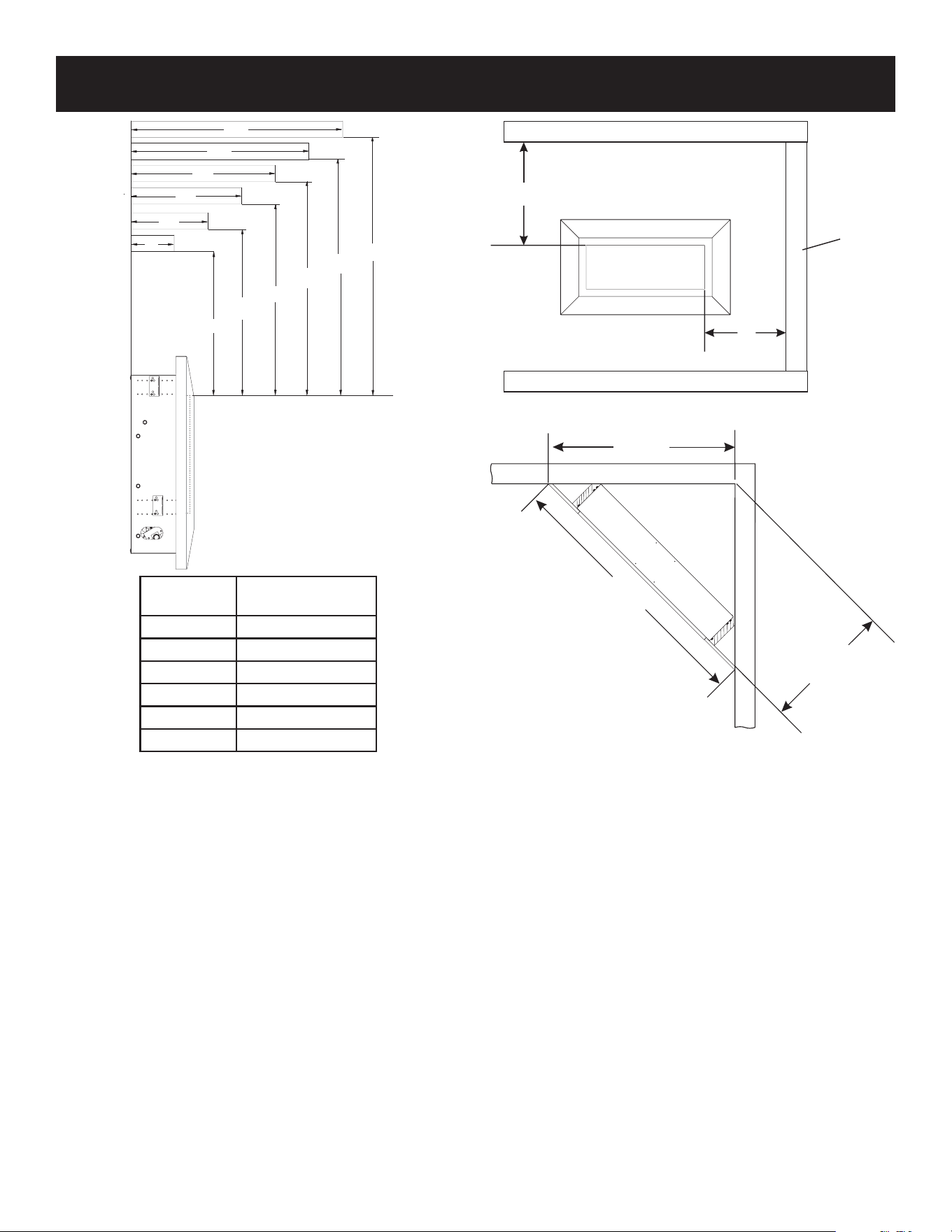
35775-0-0915Page 44
MANTEL CLEARANCES
12”
10”
8”
6”
4”
2”
OPENING
A
D
C
E
F
B
Index Letter
Dimension
(in inches)
A 18
B 20
C 22
D 24
E 26
F 28
Attention: Surface mounted installation shown. Mantel clearances
are the same for recessed, partially recessed, and surface
mounted installations.
Figure 56
Theminimumclearancefromreplaceopeningtocombustible
materialsis18inchesabovethereplaceopeningand6inches
to the side walls.
18” MIN
6”
MIN
CEILING
SIDE WALL
FLOOR
Figure 57 - Ceiling Clearance Illustration
40 3/4
28 3/4
20 3/8
Figure 58 - Corner Clearances Illustration
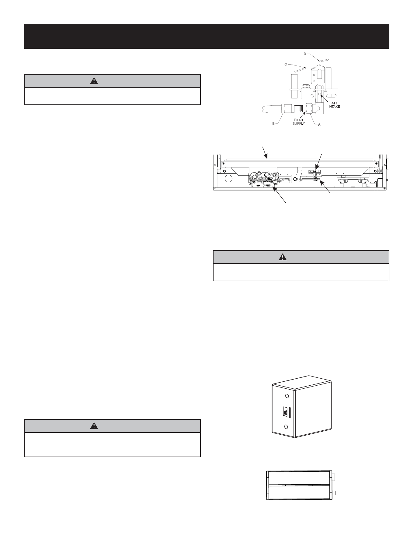
35775-0-0915 Page 45
Annual inspection and cleaning by your dealer or qualied
service technician is recommended to prevent malfunction
and/or sooting.
WARNING
Toavoidburns,turnoffreplaceandallowtocoolbefore
cleaning.
PERIODIC CLEANING - Refer to parts diagram for location of
items discussed below.
Always turn off gas to the pilot before cleaning. For relighting,
refer to lighting instructions located on the rating plate of the
replace.
• Donotusecleaninguidtocleananypartofreplace.
• Cleantheglasswithammonia-freecleaner.Ammoniawill
etch or stain glass when heated.
• Removelooseparticlesanddustfromtheburner,controls
and air shutter.
• Inspectandcleanburnerairintakehole.Removelintor
particles with brush. Failure to keep air intake hole clean will
result in sooting and poor combustion.
ANNUAL CLEANING/INSPECTION - Refer to parts diagram
for location of items discussed below.
Always turn off gas to the pilot before cleaning. For relighting,
refer to lighting instructions located on the rating plate of the
replace.
• Inspectandcleanburnerairintakehole.Removelintor
particles with vacuum or brush. Failure to keep air intake
hole clean will result in sooting and poor combustion.
• Inspectandcleanallburnerports.
• InspectODSpilotforoperationandaccumulationoflintatair
intake holes.
• Verifyamepatternforproperoperation.
• Verifysmoothandresponsiveignitionofmainburner.
CLEANING AND MAINTAINING PILOT
Oxygen Depletion Sensor Pilot
Always turn off gas to the pilot before cleaning. For relighting,
refer to lighting instructions located on the rating plate of the
replace.
Whenthepilothasalargeyellowtipame,cleantheOxygen
Depletion Sensor as follows:
1. Clean the ODS pilot by loosening nut B from the pilot tubing.
Whenthisprocedureisrequired,graspnutAwithanopen
end wrench.
2. Use canned air to blow through the holes indicated by the
arrows. This will blow out foreign materials such as dust, lint
and spider webs. Use a wrench to hold Nut A as you tighten
Nut B.
WARNING
Toavoiddamagingthepilotthatcontrolsthegasow,never
use needles, wires, or similar cylindrical objects to clean the
pilot.
3. Ifintermittentpilotunitstopsworking,cleanamesensorC
(Figure 59) with a damp cloth.
4. If intermittent pilot ignitor does not spark, clean ignitor D
(Figure 59) with a damp cloth.
A
B
C
D
PILOT
SUPPLY
AIR
INTAKE
Figure 59
GAS VALVE
PILOT TUBE
BURNER COVER
PILOT
Figure 60 (Note: Burner may vary)
CONTROL COMPARTMENT AND BURNER MAINTENANCE
Keep the control compartment and burner area clean by
vacuuming or brushing area at least twice a year.
WARNING
Thereplacecangetveryhot.Toavoidburns,handleonly
when cool.
Always turn off gas to the pilot before cleaning. For relighting,
refer to lighting instructions located on the rating plate of the
replace.
Neverobstructtheowofthecombustionandventilationair.
Keepthefrontofthereplaceclearofallobstaclesandmaterials.
Anintermittentpilotmayrequirebatterychanges.Toreplacethe
batteriesinanintermittentunitndabatterypackand/orreceiver
locationoutsideofthereplace:
1. Replace the four AA batteries in battery pack (and optional
remote receiver). The receiver has a sliding door that will
reveal the AA batteries.
OPTIONAL REMOTE RECEIVER
Figure 61
BATTERYPACK FOR
BATTERY BACK-UP
BATTERY
BACK-UP
Figure 62
CLEANING AND SERVICING
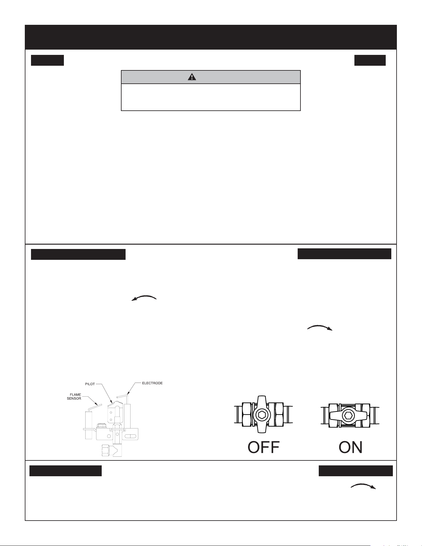
35775-0-0915Page 46
TO TURN OFF GAS TO FIREPLACE
1. STOP! Read the safety information above.
2. Turn OFF electric power to the appliance.
3. Remove the front surround panel assembly, or bottom
louver if included.
4. Turn gas valve counterclockwise
to"ON"position.
5. Wait ten minutes to clear out any gas. Then smell for gas,
includingneartheoor.Ifyousmellgas,STOP!Follow"B"
in the safety information above on this label. If you do not
smell gas, go to the next step.
6. Turn ON electric power to the appliance.
7. Find pilot - Follow metal tube from gas control. The pilot is
behind the burner on the right side.
8. Turnmainametoon.Ifthepilotdoesnotlightwithin60
seconds, stop and go to Step 5.
9. Refer to remote control instructions for detailed information,
control features, and operation. Note: There is a CPI/
IPI switch behind the right side panel that allows for a
continuous standing pilot mode or an intermittent pilot
mode. If the pilot or burner does not stay lit (in the standing
pilotmode),stopandimmediatelycallaqualiedservice
technician or gas supplier.
10. If the burner or pilot does not operate properly after several
tries, turn the gas clockwise to"OFF"andcall
your service technician or gas supplier.
11. Replace the front surround assembly or close bottom louver
assembly.
12. Operation of the gas valve is controlled by a manual on/
off switch or a hand held remote control. Refer to remote
instructions for detailed operation information.
FOR YOUR SAFETY READ BEFORE LIGHTING
A. This appliance has a pilot which can be lighted with the
manual on/off switch, a remote control, or by switching
the remote receiver switch to the "ON" position. When
lighting the pilot, follow these instructions exactly.
B. Before lighting smell all around the appliance area for
gas. Be sure to smell next to the oor because some gas
is heavier than air and will settle on the oor.
What To Do If You Smell Gas
• Do not try to light any appliance.
• Do not touch any electrical switch.
• Do not use any phone in your building.
• Immediately call your gas supplier from a neighbor's
phone. Follow the gas supplier's instructions.
• If you cannot reach your gas supplier, call the re
department.
C. Use only the remote control or manual remote receiver
switch to operate the gas valve. Never use tools. If valve
does not operate, don't try to repair it, call a qualied
service technician. Force or attempted repair may result
in a re or explosion.
D. Do not use this appliance if any part has been under
water. Immediately call a qualied service technician
to inspect the appliance and to replace any part of the
control system and any gas control which has been
under water.
LIGHTING INSTRUCTIONS
1. If applicable, turn off all electric power to the appliance if
service is to be performed.
2. If applicable, remove the surround panel assembly to gain
access to the control compartment.
3. Locate On/Off gas valve and turn clockwise
to
"OFF".Donotforce.
4. If applicable, close the bottom louver assembly.
LIGHTING INSTRUCTIONS
GAS VALVE
WARNING
Ifyoudonotfollowtheseinstructionsexactly,areor
explosion may result causing property damage, personal
injury or loss of life.
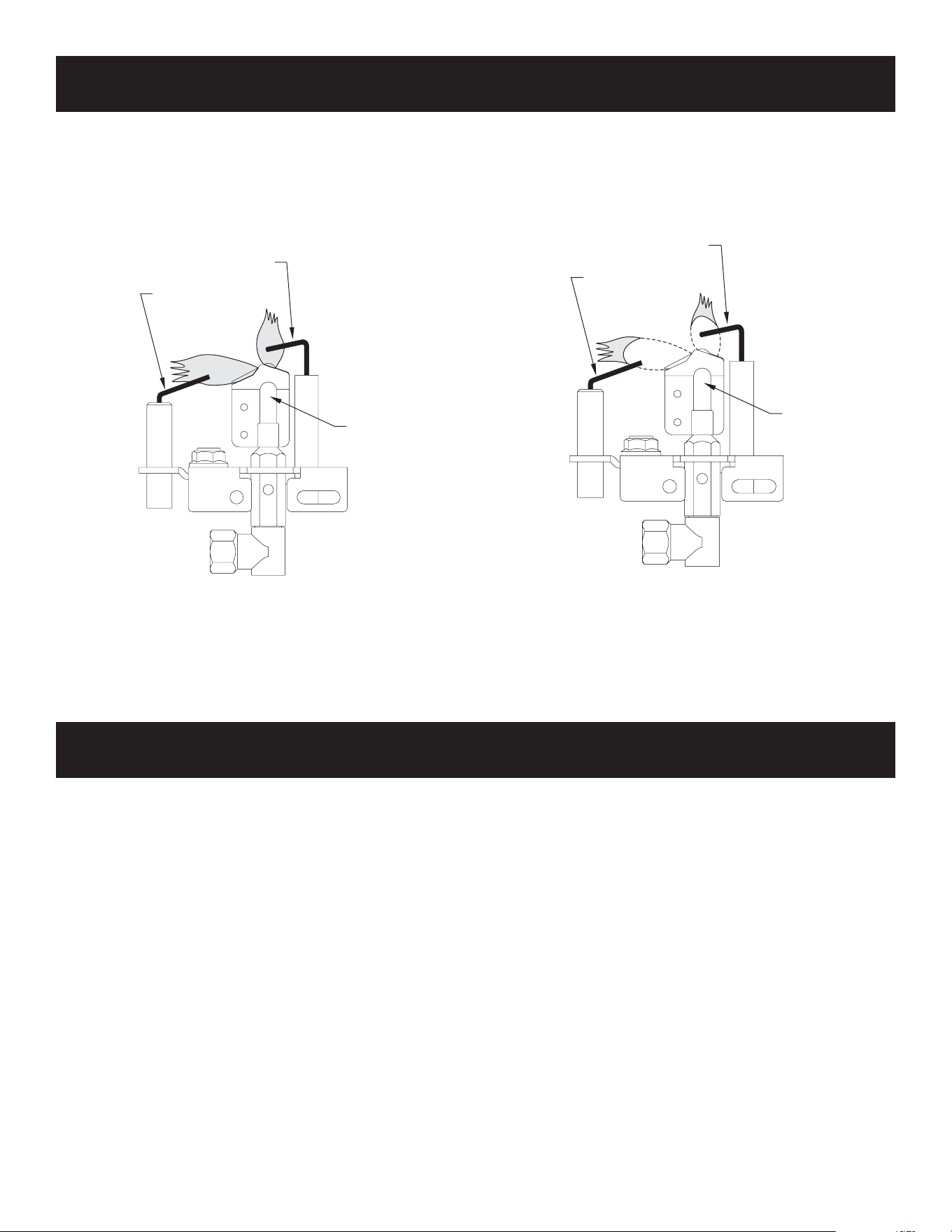
35775-0-0915 Page 47
Figure 63 showsacorrectpilotamepattern.Thecorrectame
willbeblueandwillextendbeyondtheamesensor.Theame
willsurroundtheamesensorjustbelowthetip.Aslightyellow
amemayoccurwherethepilotameandmainburnerame
meet. Figure 64showsanincorrectpilotamepattern.The
incorrectpilotameisnottouchingtheamesensor.Thiswill
causetheamesensortocool.Whentheamesensorcools,the
replacewillshutdown.
PILOT
FLAME
SENSOR
IGNITOR
Correct Pilot Flame Pattern - Figure 63
PILOT FLAME CHARACTERISTICS
PILOT
FLAME
SENSOR
IGNITOR
Incorrect Pilot Flame Pattern - Figure 64
Ifpilotamepatternisincorrect,asshowninFigure 64:
• SeeIPTroubleshooting,pages51-53.
Flamesfromthepilotaswellasthemainameshouldbevisually
checkedafterthereplaceisinstalled.
Innormaloperationatfullrateafter10to15minutes,theame
appearanceshouldbesetsofyellowames.
Notice:Allameswillberandombydesign,ameheightwillgo
up and down.
Avoidanydraftsthatalterburneramepatterns.Donotallow
fanstoblowdirectlyintooratthereplace.Donotplaceablower
insidetheburnerareaoftherebox.Ceilingfansmaycreate
draftsthatalteramepatterns.Sootingandimproperburningwill
result.
During manufacturing, fabricating and shipping, various
componentsofthisreplacearetreatedwithcertainoils,lms
or bonding agents. These chemicals are not harmful, but may
produce annoying smoke and smells as they are burned off
duringtheinitialoperationofthereplace,possiblycausing
headaches or eye or lung irritation. This is a normal and
temporary occurrence.
The initial break-in operation should last 2-3 hours. Provide
maximum ventilation by opening windows or doors to allow odors
to dissipate. Any odors remaining after this initial break-in will be
slight and will disappear with continued use.
OPERATING INSTRUCTIONS/FLAME APPEARANCE
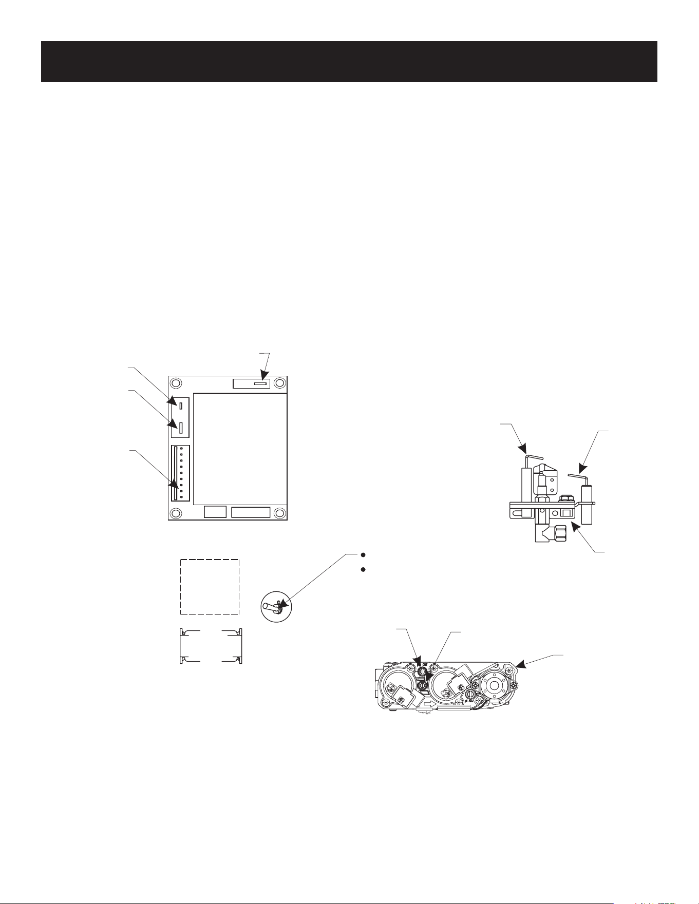
35775-0-0915Page 48
IP OPERATING INSTRUCTIONS
5.25 VDC ELECTRONIC CONTROL VALVE
The electronic control valve system includes the ability to switch
the pilot from a standing pilot mode to an intermittent pilot mode.
• IP Mode - In the Intermittent Pilot mode, when the unit is
turned ON, it will cause spark to the pilot, light the pilot,
then allow the burner to light. When the unit is turned to
OFF, both the burner and pilot will be OFF.
• CPI Mode - In the Continuous Pilot mode, the pilot
remains ON continuously even when the burner is
turned OFF.
Attention: A small toggle switch is located on a bracket beneath
the burner that is used to switch from IP (upward position) to the
CPI (downward position). See Figure 65.
When the unit is turned to ON, the electrical current will energize
a spark to the pilot igniter. Once the pilot sensor heats up (after a
fewseconds),thevalvewillbeenergized,allowinggastoowto
the burner.
1. Follow the SAFETY and LIGHTING INSTRUCTIONS for
Intermittent Pilot controls found in this manual, and on labels
found in the control compartment located in the lower cavity
ofthereplace.
2. During the operating season (or in power outage periods), it
is recommended that the pilot remain in the CPI (continuous
pilot mode) to conserve battery backup power during a
power outage.
3. The gas valve has inlet and outlet pressure taps as shown in
Figure 65.Refertopage42forgaspressurerequirements.
ELECTRONIC
CONTROL
MODULE
CONTROL
DEVICE
AA (4)
BATTERY
BACKUP
IPI
CPI
PILOT SELECTOR SWITCH
IPI - INTERMITANT PILOT (UP)
CPI - CONTINUOUS PILOT (DOWN)
IGNITOR
GROUND
9 PIN CONNECT
OR
PILOT
SENSOR
GAS VALVE
OUTLET
PRESSURE
TAP
INLET
PRESSURE
TAP
IGNITOR
FLAME
SENSOR
PILOT
ASSEMBL
Y
Figure 65
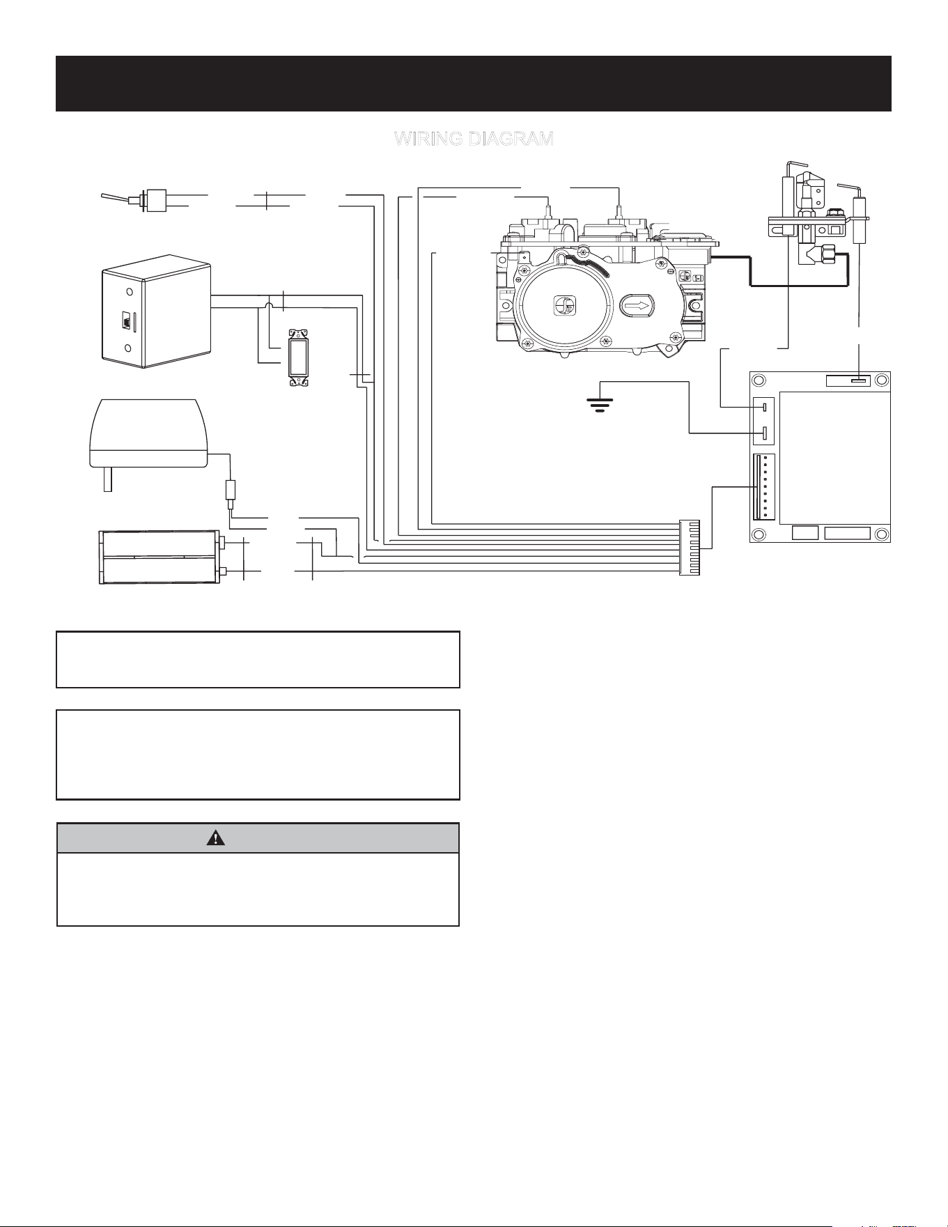
35775-0-0915 Page 49
IP WIRING
If any of the original wire as supplied with this unit must be
replaced,itmustbereplacedwithequivalentgaugeand
temperature rated wire.
Thisreplaceisonlyforusewiththetypeofgasindicated
on the rating plate and may be installed in an aftermarket,
permanently located, manufactured (mobile) home where not
prohibitedbylocalcodes.Thisreplaceisnotconvertiblefor
use with other gases.
WIRING DIAGRAM
(GND)
PILOT
CPI/IPI
SWITCH
GAS CONTROL
VALVE
ELECTRONIC
CONTROL MODULE
BATTERY HOLDER
BATTERY
BACK-UP
RED
BLACK
WHITE
BLUE
BLUE
WHITE
ORANGE
GREEN
YELLOW
BLACK
BLACK
AC/DC
POWER ADAPTOR
REMOTE RECEIVER
(OPTIONAL)
(
+ ON
REMOTE
- OFF
(
(
(
RED
BLACK
ON/OFF
SWITCH
WARNING
Improper installation, adjustment, alteration, service or
maintenance can cause property damage, personal injury or
loss of life. Installation and service must be performed by a
qualiedinstaller,serviceagencyorthegassupplier.
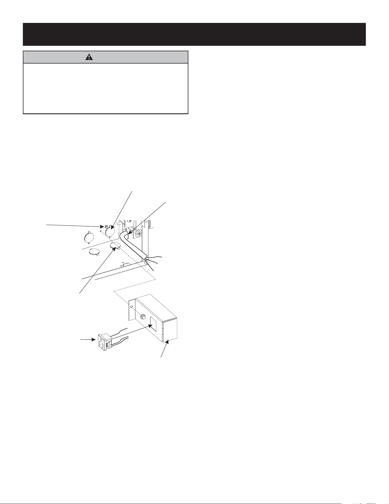
35775-0-0915Page 50
ELECTRICAL CONSIDERATIONS
CAUTION
Allwiringshouldbedonebyaqualiedelectricianandshall
be in compliance with all local, city and state building codes.
Before making the electrical connection, make sure that the
main power supply is disconnected. The appliance, when
installed, must be electrically grounded in accordance with
local codes, or in the absence of local codes, with the National
Electrical Code ANSI/NFPA 70 (Latest Edition).
A factory-installed junction box is located on the lower right
sideofthereplace.Wiringmustbefedtothejunctionboxand
attached to the receptacle that is provided. Leave approximately
6 inches of wire in the junction box for connection.
Use wire nuts to attach black wire to black wire of the receptacle
and white wire to white wire of receptacle. The ground wires
should be attached to the ground screw from the receptacle and
the 120V line.
SNAP IN
RECEPTACLE
JUNCTION BOX COVER
BOTTOM 120V LINE
REAR 120V LINE
(SURFACE MOUNT ONLY)
SIDE 120V LINE
NOTE: CHOOSE 1 OF 3
120V LINE LOCATIONS WHICH
IS NECESSARY FOR INSTALLATION
GROUND
SCREW
WHITE
COPPER WIRE
BLACK
Figure 66
35775-0-0915 Page 51
IP TROUBLESHOOTING
• The control module is an automatic gas ignition system
based on a single micro-controller core. This control
managesallfunctionsrelatedtoignition,amesensing.
• The control module can be set to provide continuous or
intermittentignitioncontrolsequencesandamemonitoring
with safety shutdown in case of failure.
• The control module is set up as a stand alone (AC powered
system with battery back up. See IP Lighting Instructions on
page 46 and Wiring Diagram on page 49.
Troubleshooting
Before proceeding to the troubleshooting table, verify that the
power supply (AC/DC adapter) is present and that the batteries
inside the optional receiver and/or battery pack are fresh and
installed with correct polarity.
Make sure all the connections between the wire harnesses and
system components are proper and positive.
If the recommended actions for the following troubleshooting
chart do not help to address the problem consider replacing the
wiring harnesses.
WARNING
Any actions performed on the gas valve must be performed in
accordance with this instruction manual. Likewise, any actions
performed on the control module or other system components
must be done in accordance with the individual component
instructions.
Replacement of components must be performed in accordance
with this instruction manual.
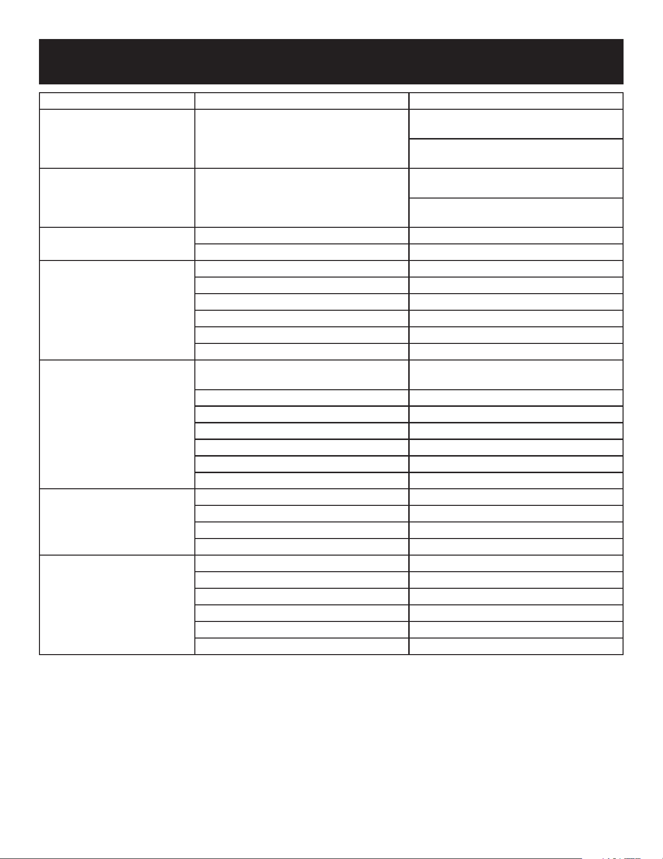
35775-0-0915Page 52
INTERMITTENT PILOT CONTROL SYSTEM TROUBLESHOOTING
PROBLEM OBSERVED POSSIBLE CAUSE CORRECTIVE MEASURE
Gas odor during setup Gas Leak
See “What to do if you smell gas” Pages 1
and 46.
Check all gas connections. Tighten all
loose connections.
Gasodorbeforerstignition Gas Leak
See “What to do if you smell gas” Pages 1
and 46.
Check all gas connections. Tighten all
loose connections.
Fireplaceis“on”butnoame
and pilot is not trying to light
Gas Line Valve turned “off” Turn shutoff valve to “open” position
Control module in “lockout” Turnreplace“off”andthenback“on”
Pilot continues to spark when
pilot is lit.
Not enough gas to pilot Waitforpilotametostrengthen
Low Gas Pressure Check pressures. See page 6.
Pilot igniter/sensor is dirty Clean pilot. See maintenance page 45.
Pilot not grounded well Check ground connections
Draftinrebox Redirect draft from room or wall
Pilot sensor has been bent Replace pilot
Pilot will not ignite, or will not
stay lit
Pilot igniter/sensor is dirty
Cleanamesensorandpilotigniter.See
maintenance page 45.
Pilot not grounded well Check ground connections
Sensor Wire loose Check sensor wire terminals
Gas pressure incorrect Adjust gas pressure
Pilot Gas Line bent or kinked Replace pilot tube
Faulty pilot, Sensor bent Replace Pilot
Faulty valve Replace Valve
Burner takes too long to fully
light
Low gas pressure Check gas supply pressure
Clogged or dirty carryover/burner ports Clean ports
Blockedorice Checkoriceopening
Faulty valve Replace valve
Burner does not light but pilot
remains on
Low gas pressure Check gas supply pressure
Clogged or dirty burner ports Clean burner ports
Blockedorice Checkoriceopening
Loose wire connections Check valve/control module connections
Faulty pilot Replace pilot
Faulty valve Replace valve
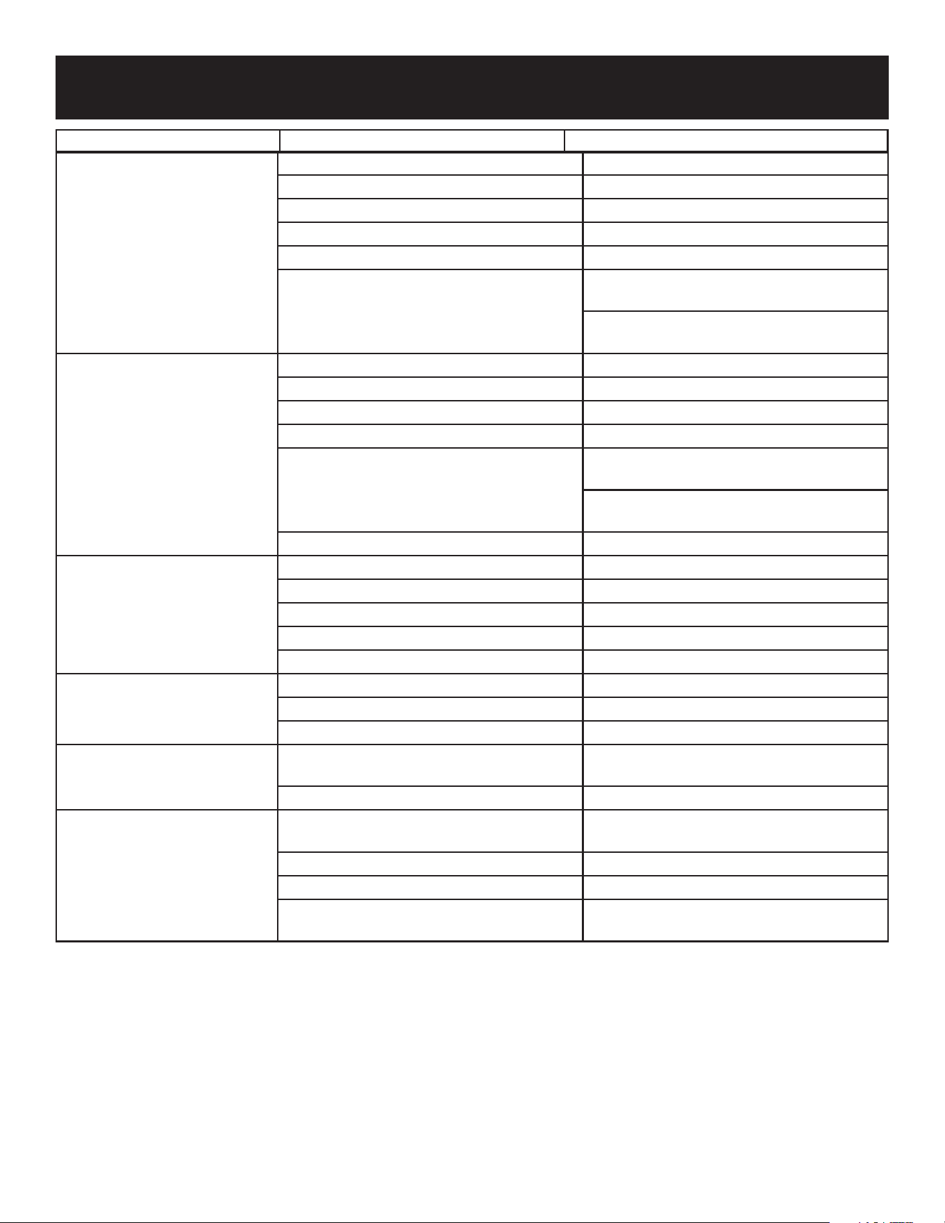
35775-0-0915 Page 53
INTERMITTENT PILOT CONTROL SYSTEM TROUBLESHOOTING
Burner lights but does not stay
lit while pilot remains on
Low gas pressure Check gas supply pressure
Loose sensor wire Check wire connection
Faulty valve Replace valve
Faulty pilot or thermocouple Replace Safety pilot
Clogged or dirty burner ports Clean burner ports
(Forreplaceequippedwithoptional
thermostat or thermostat remote) Room
temperature is higher than thermostat
setting
Move (optional) remote away from
replace
Set higher temperature on (Optional)
remote/thermostat
Burner & pilot light but will not
stay lit
Flame sensor dirty Clean pilot sensor
Low gas pressure Check gas supply pressure
Not enough fresh air for pilot Open door or window - ventilate
Clogged or dirty burner ports Clean burner ports
(Forreplaceequippedwithoptional
thermostat or thermostat remote) Room
temperature is higher than thermostat
setting
Move (optional) remote away from
replace
Set higher temperature on (Optional)
remote/thermostat
Faulty pilot or thermocouple Replace pilot
Incorrectburnerame
Incorrect gas supply or pressure Check gas supply pressure
Blockedorice Checkoriceopening
Clogged or dirty burner ports Clean burner ports
Faulty valve Replace valve
High altitude Adjustoricesizeforaltitude
Backreofburner
Blockedorice Checkoriceopening
Clogged or dirty burner ports Clean burner ports
Low gas pressure Check gas supply pressure
Appliance produces unwanted
odors
Vapors from paint, hairspray, glue, etc.
Ventilate room until odor stops. Do not use
paint,hairspray,glue,etcaroundreplace
Initial burn-off of manufacturing chemicals Ventilate room until odor stops
Whistle noise from appliance
Check gas pressure
Adjust gas pressure to recommended
setting.
Air in gas line Bleed lines
Control knob not in fully open position Open control knob to full position
Spiralgasexlinepinchedortoosmall
diameter line
Straightenexlinewherepinchedor
replace gas feed line with larger diameter
PROBLEM OBSERVED POSSIBLE CAUSE CORRECTIVE MEASURE

35775-0-0915Page 54
PARTS LIST
Index
Number
Part Number Description
VFSL30FP70(N,P) VFSL30FP7010(N,P)
1 35700 35351 Burner Plate Assembly, Black
2 35699 35699 Screen Assembly, Black
3 35551 35551 Valve Bracket
4 35552 35552 Control Module Bracket
5 35547 35547 Junction Box
6 35555 35555 Nailing Flange (4 supplied)
7 R11232 R11232 Glass Panel
8 35548 35348 Burner Assembly Bracket
9 35539 35539 Outer Wrapper Front
10 R11210 R11210 Valve - Nat
10 R11211 R11211 Valve - LP
11 R11127 R11127 Control Module
12 R11328 R11328 Pilot - Nat
12 R11327 R11327 Pilot - LP
13 FWS1 FWS1 Switch and Cover
14 R12144 R12144 Switch Extension Harness
15 R11332 R11332 Wire Sensor
16 R11333 R11333 Wire Ignitor
17 R11123 R11123 Wire Harness - Valve
19 P245 P293 Orice-Nat
19 P315 P193 Orice-LP
20 P313 P313 OriceHolder
21 R12092 R12249 Burner - Nat
21 R12093 R12250 Burner - LP
22 35763 35763 Tubing, Valve to Regulator - Nat
23 35764 35764 Tubing, Regulator to Pilot - Nat
24 35765 35765 Tubing, Valve to Pilot - LP
25 B100100 B100100 Brass 3/8-inch Flare Fitting
26 R11128 R11128 Power Adaptor
27 R11122 R11122 Battery Pack
28 R7063 R7063 Regulator, 5 w.c. - Nat
29 R9987 R9987 Flexline
30 R12091 R12091 Cord Grip
31 R12097 R12097 OriceGasket-Nat
32 R11441 R11441 Snap-In Receptacle
33 35754 35754 Non-Combustible Board - Top
34 35755 35755 Non-Combustible Board - Side (2 supplied)
35 WXB10 WXB10 Backup Battery Extension Wire
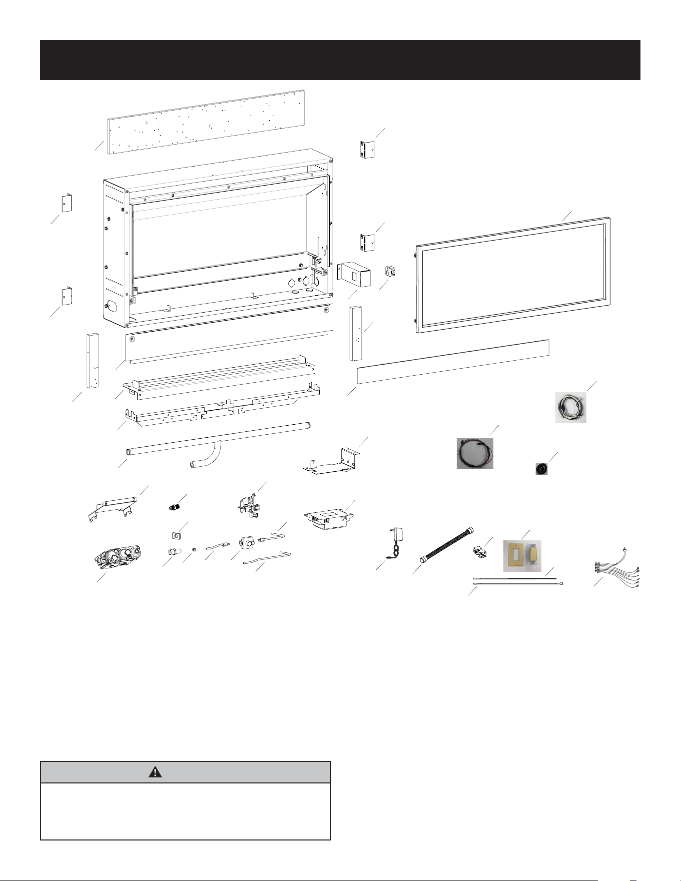
35775-0-0915 Page 55
EXPLODED VIEW
17
16
13
27
15
29
26
11
4
7
35
30
24
28
22
19
20
10
31
23
12
25
3
21
8
34
5
32
2
6
33
6
6
6
14
9
34
1
WARNING
Failure to position the parts in accordance with these
diagramsorfailuretouseonlypartsspecically
approved with this appliance may result in property
damage or personal injury.

35775-0-0915Page 56
To Order Parts Under Warranty, please contact your local Empire dealer. See the dealer locator at www.empirecomfort.
com. To provide warranty service, your dealer will need your name and address, purchase date and serial number, and the
nature of the problem with the unit.
To Order Parts After the Warranty Period, please contact your dealer or one of the Master Parts Distributors listed below.
This list changes from time to time. For the current list, please click on the Master Parts button at www.empirecomfort.com.
Please note: Master Parts Distributors are independent businesses that stock the most commonly ordered Original
EquipmentrepairpartsforHeaters,Grills,andFireplacesmanufacturedbyEmpireComfortSystemsInc.
MASTER PARTS DISTRIBUTOR LIST
Parts Not Under Warranty
Parts can be ordered through your Service Person, Dealer, or a Master Parts Distributor. See this page for the Master Parts Distributors
list. For best results, the service person or dealer should order parts through the distributor. Parts can be shipped directly to the
service person/dealer.
Warranty Parts
Warranty parts will need a proof of purchase and can be ordered by your Service Person or Dealer. Proof of purchase is required for
warranty parts.
AllpartslistedinthePartsListhaveaPartNumber.Whenorderingparts,rstobtaintheModelNumberandSerialNumberfromthe
nameplateonyourequipment.ThendeterminethePartNumber(not the Index Number) and the Description of each part from the
following illustration and part list. Be sure to give all this information . . .
Fireplace Model Number Part Description
Fireplace Serial Number Part Number
Type of Gas (Propane or Natural)
Do not order bolts, screws, washers or nuts. They are standard hardware items and can be purchased at any local hardware store.
Shipmentscontingentuponstrikes,resandallcausesbeyondourcontrol.
HOW TO ORDER REPAIR PARTS
Dey Distributing
1401 Willow Lake Boulevard
Vadnais Heights, MN 55101
Phone: 651-490-9191
Toll Free: 800-397-1339
Website: www.deydistributing.com
Parts: Heater, Hearth and Grills
Victor Division of F. W. Webb Company
200 Locust Street
Hartford, CT 06114
Phone: 860-722-2433
Toll Free: 800-243-9360
Fax: 860-293-0479
Toll Free Fax: 800-274-2004
Websites: www.fwwebb.com & www.victormfg.com
Parts: Heater, Hearth and Grills
East Coast Energy Products
10 East Route 36
West Long Branch, NJ 07764
Phone: 732-870-8809
Toll Free: 800-755-8809
Fax: 732-870-8811
Website: www.eastcoastenergy.com
Parts: Heater, Hearth and Grills
35775-0-0915 Page 57
APPLIANCE SERVICE HISTORY
Date Dealer Name Service Technician Name Service Performed/Notes
35775-0-0915Page 58
APPLIANCE SERVICE HISTORY
Date Dealer Name Service Technician Name Service Performed/Notes

35775-0-0915 Page 59
WARRANTY
Empire Comfort Systems Inc. warranties this hearth product to be free from defects at the time of purchase and for the
periodsspeciedbelow.Hearthproductsmustbeinstalledbyaqualiedtechnicianandmustbemaintainedandoperated
safely,inaccordancewiththeinstructionsintheowner’smanual.EmpirewillnotwarrantyanyBoulevardreplacethatis
not installed by the selling dealer or that dealer’s direct contract agents.
This warranty applies to the original purchaser only and is not transferable. All warranty repairs must be accomplished by
aqualiedgasappliancetechnician.
Limited Lifetime Parts Warranty with a Five-Year
Limited Labor Warranty – Combustion Chamber and
Heat Exchanger
• Ifthecombustionchamberorheatexchanger(see
parts list) fails because of defective workmanship or
material, Empire will repair or replace at Empire’s
option.
• Withinveyearsfromthedateofpurchase,Empire
will pay reasonable labor to have the defective part
repaired or replaced at Empire’s option.
Limited Five-Year Parts & Labor Warranty – All Other
Components (Except Remote Controls, Thermostats,
Accessories and Replacement Parts)
• Shouldanypartfailbecauseofdefective
workmanshipormaterialwithinveyearsfromthe
date of purchase, Empire will repair or replace at
Empire’s option.
• Withinveyearsfromthedateofpurchase,Empire
will pay reasonable labor to have that defect repaired
at Empire’s option.
Limited One-Year Parts Warranty – Remote Controls,
Thermostats, Accessories, and Parts
• Shouldanyremotecontrol,thermostat,accessory,
or other part fail because of defective workmanship
within one year from the date of purchase, Empire will
repair or replace at Empire’s option.
Duties Of The Owner
• Theappliancemustbeinstalledbyaqualied
installer and operated in accordance with the
instructions furnished with the appliance.
• Abillofsale,cancelledcheck,orpaymentrecord
should be kept to verify purchase date and establish
warranty period.
• Readyaccesstotheapplianceforservice.
What Is Not Covered
• Damagesthatmightresultfromtheuse,misuse,or
improper installation of this appliance.
• Travel,diagnosticcostsandfreightchargeson
warranted parts to and from the factory.
• Claimsthatdonotinvolvedefectiveworkmanshipor
materials.
• Unauthorizedserviceorpartsreplacements.
• Removalandreinstallationcost.
• Inoperableduetoimproperorlackofmaintenance.
How To Get Service
• Tomakeaclaimunderthiswarranty,pleasehave
your receipt available and contact your installing
dealer. Provide the dealer with the model number,
serialnumber,typeofgas,andpurchaseverication.
The installing dealer is responsible for providing
service and will contact the factory to initiate any
warranted parts replacements. Empire will make
replacement parts available at the factory. Shipping
expenses are not covered.
• If,aftercontactingyourEmpiredealer,service
received has not been satisfactory, contact:
Consumer Relations Department, Empire Comfort
Systems Inc., PO Box 529, Belleville, Illinois 62222,
or send an e-mail to [email protected] with
“Consumer Relations” in the subject line.
Your Rights Under State Law
• Thiswarrantygivesyouspeciclegalrights,andyou
may also have other rights, which vary from state to
state.

35775-0-0915Page 60
Empire Comfort Systems Inc.
918 Freeburg Ave. Belleville, IL 62220
Ifyouhaveageneralquestionaboutourproducts,pleasee-mailusat
Ifyouhaveaserviceorrepairquestion,pleasecontactyourdealer.
www.empirecomfort.com