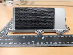

LinkTag20
Manual
Revision History
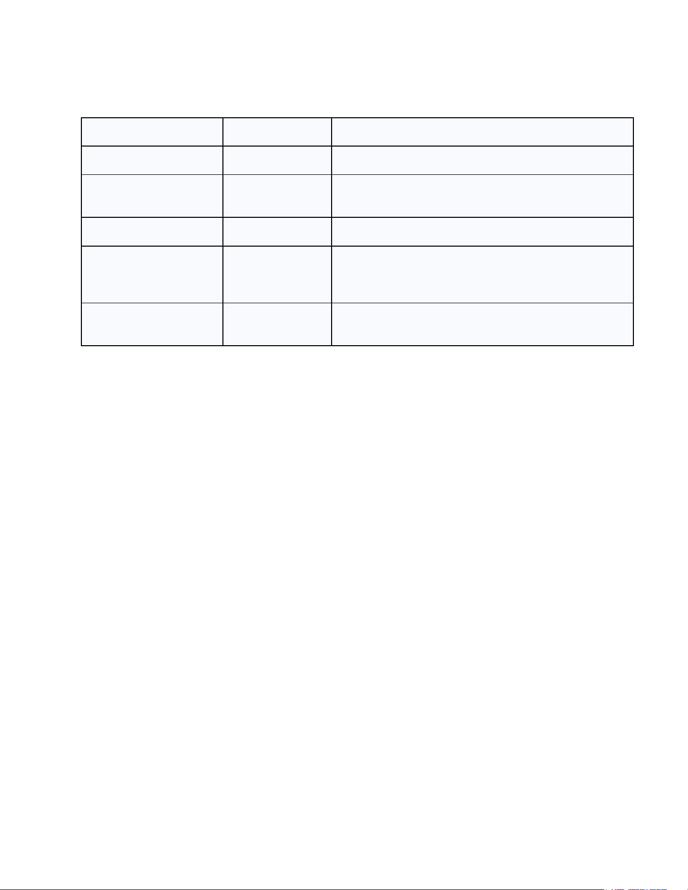
Date
Version
Description
Nov 14, 2025
V 1.0
Initial version
Nov 30, 2025
V 1.1
Updated with FW 1.0.3 specifications and
hardware photos
Feb 3, 2026
V 1.2
Updated with FW 1.0.5 specifications
Mar 5, 2026
V 1.3
Updated with technical specifications and
regulatory information for Mexico IFT certification
compliance.
Mar 6, 2026
V 1.4
Added FCC compliance and RF exposure
statement (Section 8).

Contents
1. Product Introduction ............................................................................................................. 4
1.1 Overview .................................................................................................................. 4
1.2 Features ................................................................................................................... 4
1.3 Regulatory and Safety Information ........................................................................ 5
2. Hardware Introduction .......................................................................................................... 6
2.1 Development Specifications ................................................................................... 6
2.2 BLOCK DIAGRAM .................................................................................................... 7
2.3 Hardware Components ........................................................................................... 7
3. Device Installation ................................................................................................................. 8
3.1 Power Activation and Network Preparation ........................................................... 8
3.2 Physical Mounting and Orientation ........................................................................ 8
3.3 Firmware Management ............................................................................................ 8
4. Operation and Working Principle ......................................................................................... 9
4.1 Summary of Operating Modes ................................................................................ 9
4.2 Automatic Operation Flow ...................................................................................... 9
4.2.1 Install Mode (Installation and Field Verification) .......................................... 9
4.2.2 Standing State (Stationary State - General Mode) ...................................... 10
4.2.3 Moving State (In-Motion State - General Mode) .......................................... 10
4.2.4 Model-Specific Behavior .............................................................................. 11
5. Device Specifications ......................................................................................................... 12
5.1 Configuration ......................................................................................................... 12
5.2 LoRaWAN Configuration ....................................................................................... 12
5.3 LED Behavior ......................................................................................................... 13
5.4 Button Behavior ..................................................................................................... 14
6. Communication Overview .................................................................................................. 15
6.1 STM UART Communication .................................................................................. 15
6.2 LoRaWAN Communication ................................................................................... 15
6.3 Notice ..................................................................................................................... 16
7. Warranty Information .......................................................................................................... 17
7.1 Warranty Period ..................................................................................................... 17
7.2 Coverage ................................................................................................................ 17
7.3 Warranty Exclusions ............................................................................................. 17
7.4 Claim Procedure .................................................................................................... 17
8. Regulatory Information ....................................................................................................... 18

1. Product Introduction
1.1 Overview
The LinkTag20 is a fully autonomous GPS tracking device operating in the LoRaWAN US915
band. It is designed for the long-range wireless transmission of location and device status data
with minimal user interaction.
The device periodically acquires GNSS coordinates, evaluates movement using an integrated
IMU, and transmits the location, battery status, and operational metrics to the LoRaWAN
network via unconfirmed uplink messages. It automatically determines its operational state
(Standing or Moving) and adjusts its reporting interval accordingly to maximize power efficiency.
Once deployed, the device operates independently in outdoor environments without requiring
additional configuration or control by the user. This makes the LinkTag20 suitable for asset
tracking, equipment monitoring, infrastructure management, and other field applications.
The LinkTag20 is a high-performance, solar-assisted wireless tracking device designed for long-
range asset monitoring and data logging. The product is intended to be used by end-users
without requiring disassembly, modification, or access to the internal firmware interface.
1.2 Features
● LoRaWAN US915 Compliance: Supports LoRaWAN 1.0.3 in the US915 frequency band
using the Quectel KG200Z module. All application data is transmitted via unconfirmed
uplink messages.
● High-Precision GNSS: The integrated Quectel LC76G GNSS receiver provides accurate
latitude and longitude data.
● Autonomous Operating Cycle: Upon activation, the device continuously performs GNSS
acquisition, data transmission, and low-power standby mode in a fully automated manner.
● Integrated Motion Detection: Equipped with a TDK ICM-42670-P IMU that allows for
reliable Standing/Moving state classification and motion-triggered activation.
● Adaptive Reporting Logic: Reporting intervals are automatically adjusted based on the
device's movement state to optimize battery life.
● Low Power Design: Utilizes RTC-based wake-up scheduling and STOP2 low-power mode
for an extended operational lifespan.
● Outdoor Environmental Resistance: Designed to withstand temperature variations,
humidity, and dust exposure typical of long-term outdoor installations.
● Reliable Data Retention: The device stores uplink data in its internal Flash memory only
when a connection attempt fails (e.g., gateway out of range). Stored data is buffered and
retransmitted during the next successful cycle.
● Optional Solar Charging: Supports supplementary charging via an external photovoltaic
module.

1.3 Regulatory and Safety Information
Regulatory Compliance
This device is designed to comply with international regulations applicable to
radiocommunication equipment, including the requirements established by the IFT of Mexico
and other regional authorities. The device must be operated in accordance with the instructions
provided in this manual.
Any unauthorized modification, disassembly, software alteration, or replacement of parts may
void the regulatory approval, certification status, and manufacturer's warranty. Users are
prohibited from making changes that may affect radio performance, frequency operation,
transmission characteristics, or the security functionality of the device. Only accessories,
antennas, and components approved by the manufacturer should be used.
Safety Instructions
● Do not expose the device to excessive heat or fire for prolonged periods.
● Do not submerge the device in water unless it is specifically rated as waterproof.
● Do not operate the device in environments with explosive gases or flammable materials.
● Do not attempt to open, disassemble, puncture, repair, or modify the device or its internal
battery.
● Avoid dropping or subjecting the device to strong physical shocks.
● Keep the device out of reach of children and pets.
● Dispose of the device and internal battery in accordance with local e-waste recycling
regulations.
● If abnormal heat, smoke, swelling, noise, or odor is detected, contact authorized service
personnel immediately.
2. Hardware Introduction
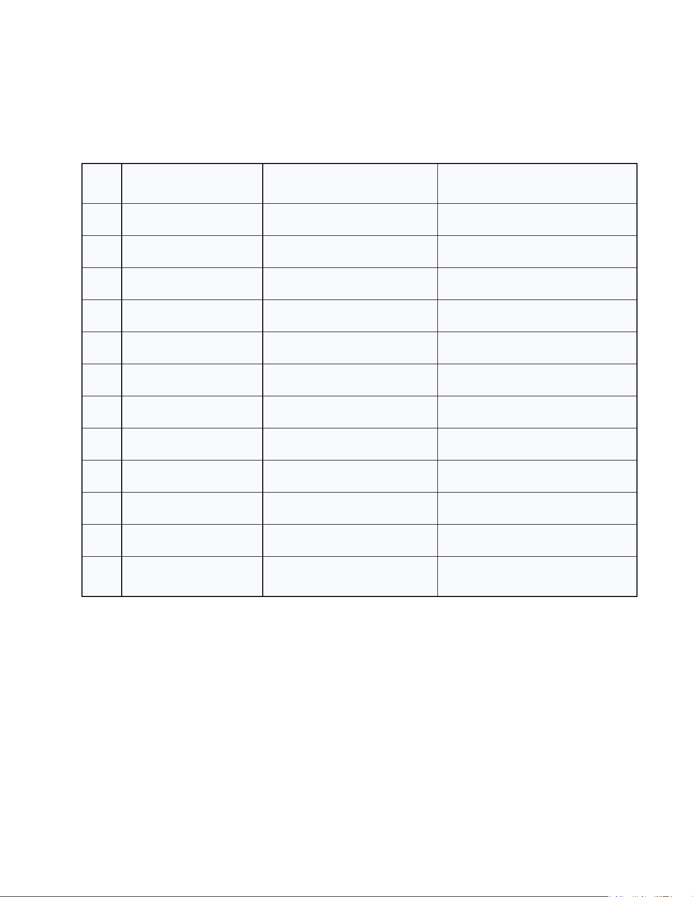
2.1 Development Specifications
NO.
Descriptions
SPEC
NOTE
1
LoRa RF Frequency
902.3MHz ~ 927.5MHz (200kHz)
2
Spreading Factor
SF 7
3
Total Channels
127 Channels
FCC certified range
4
LoRa Bandwidth
125kHz
5
LoRa RF TX Power
20dBm
6
BATTERY
Li-Polymer (3.7V/4000mAh)
7
Solar Charging
Vmp 6V / Imp 167mA
8
GNSS
L1
9
LoRa Communication Range
Up to 10km
Open area
10
LoRa Antenna
PCB Antenna
11
GNSS Antenna
Patch Antenna
12
Flash Memory
32MB
Configurable storage up to 15 days. FIFO
structure.
The RF hardware supports configurable channel allocation; however, the regulatory operating
configuration is defined in Section 5.2.
2.2 Hardware Components
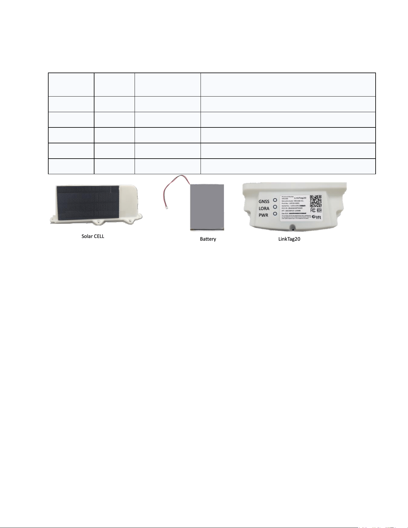
Component
Indicator
Function
Description
LED
GNSS
GNSS Indicator
Indicates GNSS function status and satellite positioning.
LED
LORA
LoRa Indicator
Indicates LoRaWAN communication and data transmission status.
LED
PWR
Charge Indicator
Shows the current battery charge and power status.
Solar CELL
Solar Module
High-efficiency solar panel for supplementary charging.
Battery
Rechargeable Battery
Internal battery (3.7V/4,000mAh) that powers the device.

3. Device Installation
3.1 Power Activation and Network Preparation
● Simple Activation: The device does not require special manual procedures. Upon
applying battery power, it automatically begins to operate according to the flow described in
Section 4.
● Mandatory Network Configuration: To comply with IFT regulations, the device must be
registered on the authorized LoRaWAN gateway server prior to deployment.
● Boot Signal: Confirm the status by observing that the GNSS and LoRa LEDs blink once
simultaneously immediately after power is applied.
3.2 Physical Mounting and Orientation
● Upward Orientation: The device must be installed with the Solar Cell facing upwards
(directly towards the sky).
● Optimal Performance: This orientation is essential for the internal GNSS antenna to
maintain a line of sight with satellites and for the Solar Cell to charge the battery.
● Secure Fixation: Firmly attach the device to a flat surface using high-strength adhesives
or screws.
3.3 Firmware Management
The firmware comes pre-installed from the factory. Any maintenance is performed exclusively
by authorized personnel. Debugging or ST-LINK instructions are omitted from this manual.
4. Operation and Working Principle
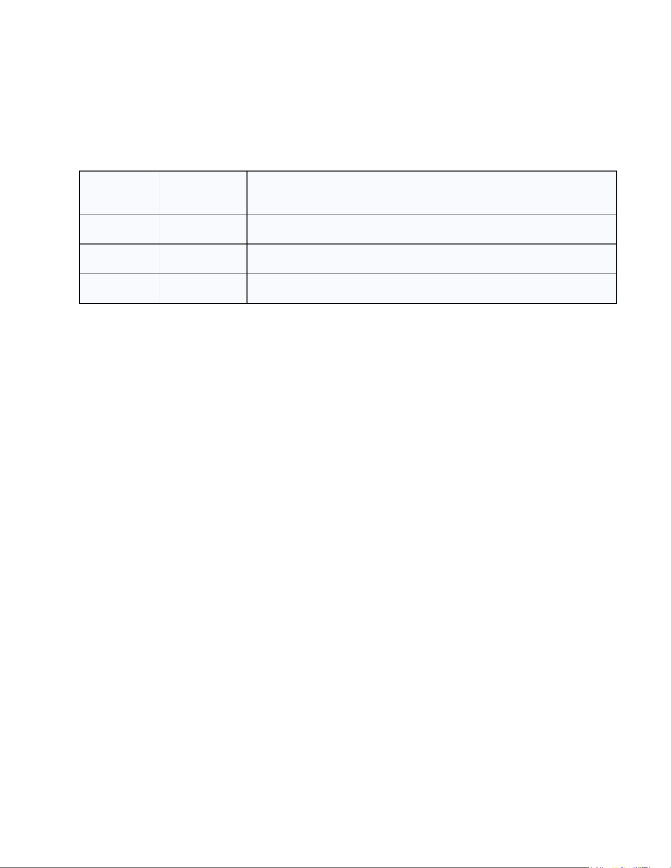
4.1 Summary of Operating Modes
Mode
State
Function
Install
-
Verification mode for GNSS/LoRa via LEDs during deployment.
General
Standing
Low-power mode activated when no movement is detected.
General
Moving
Active tracking mode triggered by movement.
4.2 Automatic Operation Flow
Upon field deployment, LinkTag20 operates autonomously based on its embedded algorithms
without requiring manual user intervention. The operational phases are divided into Install Mode
for initial verification and General Mode for real-time operation.
4.2.1 Install Mode (Installation and Field Verification)
Designed for installers to verify data acquisition and communication immediately upon deploying
the device.
[Detailed Operational Flow]
1. Power Application (ON): The system initiates booting. Upon completion, the GNSS and
LoRa LEDs blink once.
2. GNSS Positioning: Performs positioning for a maximum of 2 seconds.
○ In progress: GNSS LED blinks (1/sec).
○ Success: GNSS LED solid ON.
○ Failure: GNSS LED blinks rapidly.
3. LoRa Communication: Communicates with the LoRaWAN server.
○ In progress: LoRa LED blinks (1/sec).
○ Success: LoRa LED solid ON.
○ Failure: LoRa LED blinks rapidly.
4. State Maintenance: LEDs maintain their state for installer verification.
5. Cycle and Transition: The sequence repeats for five (5) cycles, then automatically
transitions to the Standing state.
4.2.2 Standing State (Stationary State - General Mode)
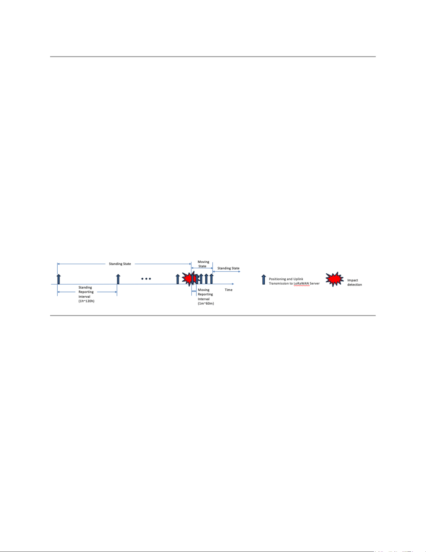
Minimizes power consumption while the asset is stationary.
[Detailed Operational Flow]
1. RTC Wake-up: The system wakes up based on the internal Real-Time Clock.
2. GNSS and Data: Performs positioning for a maximum of 5 minutes.
3. LoRa Connectivity: Checks session status. If not connected, attempts to connect (Default:
2 retries, range: 1 to 12).
4. LoRa Transmission: Sends current data and any data stored in Flash.
5. Verification: If successful, prepares for the next cycle. If it fails, stores the data in Flash for
retransmission.
6. Configurable Interval: Default 24 hours (range 1 to 120 hours).
7. Deep Sleep: Enters ultra-low power mode immediately after transmission.
[State Transition]
● To Moving State: Transitions immediately if the IMU detects acceleration exceeding the
threshold (Default: Level 1 / 80mg).
4.2.3 Moving State (Motion State - General Mode)
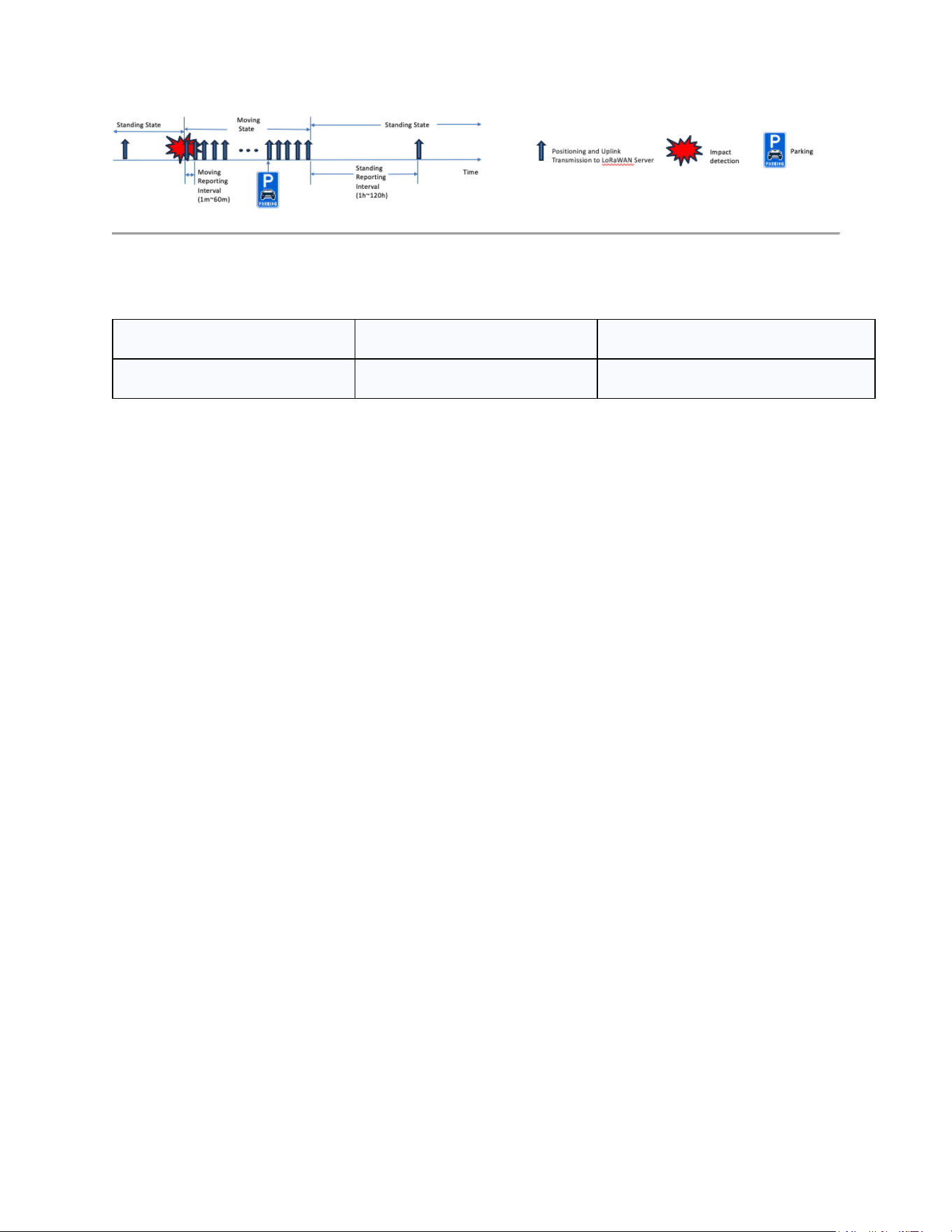
Activated upon detecting movement and focuses on high-frequency tracking.
[Detailed Operational Flow]
1. RTC Wake-up: Wakes up based on the internal RTC.
2. GNSS and Data: Performs positioning and data collection for 2 seconds.
3. LoRa Connectivity: Checks session status. If not connected, attempts to connect (Default:
2 retries, range: 1 to 12).
4. LoRa Transmission: Sends current data and any data stored in Flash.
5. Verification: If successful, prepares for the next cycle. If it fails, stores the data in Flash for
retransmission.
6. Reporting Loop: Repeats according to the Moving Reporting Interval (Default: 1 min).
[State Transition]
● To Standing State: Returns if no movement is detected for 5 times the reporting interval
AND the GNSS speed (SOG) is ≤ 1 knot.
4.2.4 Model-Specific Behavior
Model
Battery Format
Low Battery Warning
Solar Charging Model
0–100% (1% resolution)
Below 5%
5. Device Specifications
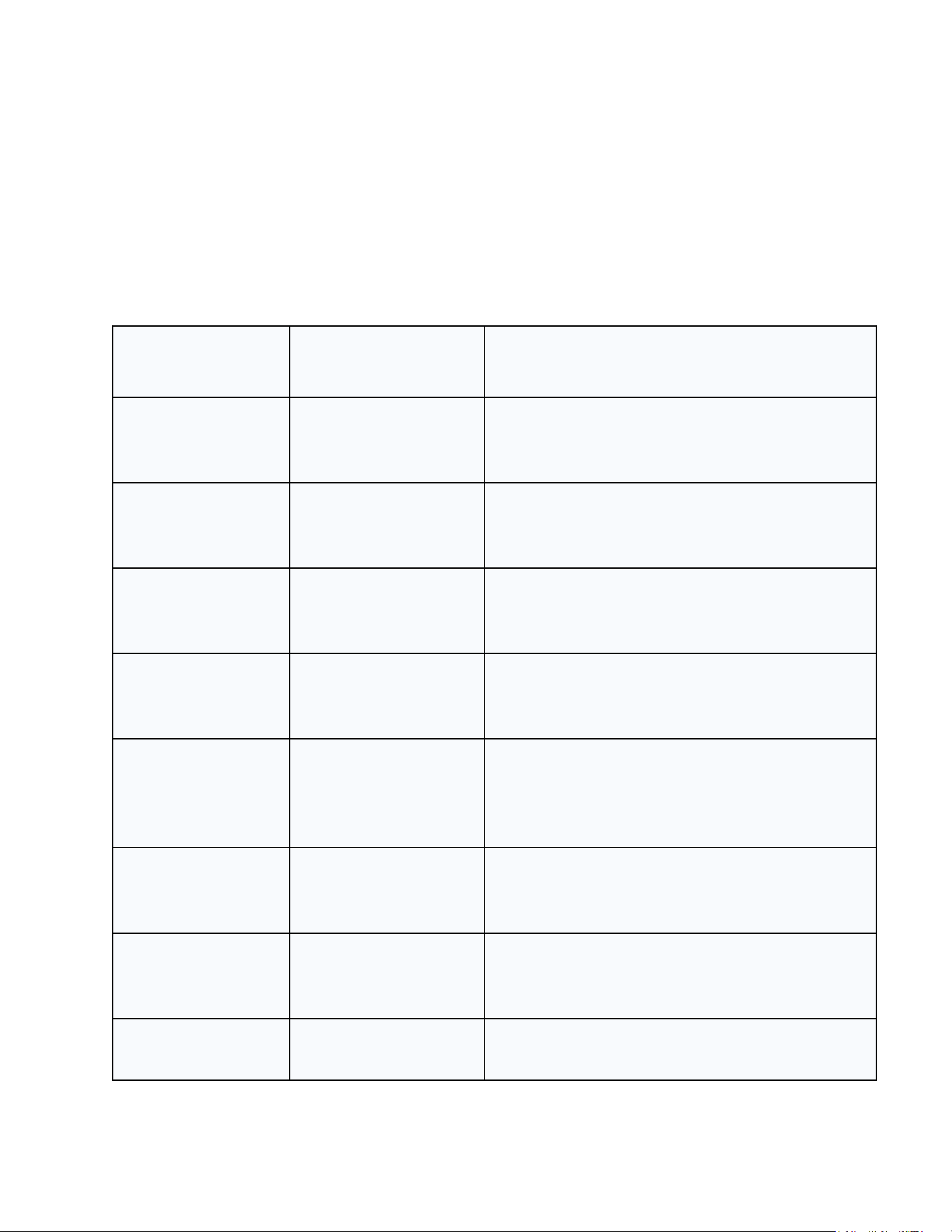
5.1 Configuration
The following are the default configuration values stored in the device.
All items can be modified through the communication protocol.
Item
Default Value
Description
LoRa Retries
2
Join attempts (range 1–12)
Moving Interval
1 min
Interval in moving state (range 1–60)
Standing Interval
24 h
Interval in stationary state (range 1–120)
Flash Retention
7 days
Days of storage in Flash (range 1–15)
IMU Threshold
3
Sensitivity: 0=50mg, 1=80mg, 2=100mg,
3=200mg, 4=400mg, 5=600mg, 6=800mg,
7=1000mg.
IMU Mode
0
0=OR Logic / 1=AND Logic
IMU Duration
1
0=1st event, 1=2nd, 2=3rd, 3=4th
Battery Mode
0
0 = solar charging model
5.2 LoRaWAN Configuration
The following configuration represents the operational configuration evaluated for regulatory
compliance.
The commercial firmware configuration evaluated for regulatory compliance is as follows:
● Join Method: OTAA
● Class: A
● Region: US915
● TX Power: +20 dBm
● DR: 3 (SF7 / 125kHz)
5.3 LED Behavior
The PWR LED indicates the battery charging state.
The LoRa and GNSS LEDs (BLUE) are active only during:
● Install Mode
Low-battery thresholds differ by model (see Section 4.2.4).
Function
Action
General
Install Mode
Battery
Charging
LED PWR ON
LED PWR ON
Not charging
LED PWR OFF
LED PWR OFF
Boot
Startup ready
LORA/GNSS OFF
1 BLINK
Sleep
Low power
LORA/GNSS OFF
LORA/GNSS OFF
GPS
Fix attempt
GNSS OFF
SLOW BLINK
Success
GNSS OFF
LED ON
Failure
GNSS OFF
FAST BLINK
LoRa
Connecting
LORA OFF
SLOW BLINK
Success
LORA OFF
LED ON
Failure
LORA OFF
FAST BLINK
5.4 Button Behavior
The device includes two physical buttons: a Reset Button and a Test Button, each providing
distinct hardware-level and firmware-level functionality. The operational behavior of these
buttons is described below.
Button
Duration
Action
Description
Reset
Short click
Hardware Reset
Immediate reset. Does not erase
data.
Test
1–3 sec
Config Reset
Restores factory defaults and
reboots.
Test
> 3 sec
Test Mode
Factory functional test mode.

6. Communication Overview
The LinkTag20 supports two communication interfaces during normal operation:
UART for basic maintenance tasks and LoRaWAN for long-range wireless communication.
This section provides a high-level description of each interface required for standard device
usage. Developer-level protocol details, payload definitions, and internal command structures
are intentionally omitted from this manual.
6.1 STM UART Communication
The UART interface is intended for authorized maintenance and diagnostics, allowing users to
interact with the device to check or update configuration settings.
UART Settings
● Baudrate: 115200
● Data Bits: 8
● Stop Bit: 1
● Parity: None
● Flow Control: None
The UART interface is available only when the MCU is awake. When the device enters low-
power mode, the UART interface is automatically disabled.The UART interface is not required
for normal user operation and is used solely for service or technical support purposes.
6.2 LoRaWAN Communication
The LinkTag20 communicates with the network server using LoRaWAN unconfirmed uplink
messages without requiring acknowledgment.
Operating Parameters
● LoRaWAN Version: 1.0.3
● Region: US915
● Join Method: OTAA
During normal operation, the device automatically performs the following tasks:
● Joining the LoRaWAN network
● Transmitting GNSS and sensor data via uplink
All LoRaWAN-related processes are handled internally by the firmware. No user configuration
or manual intervention is required.

6.3 Notice
Detailed payload formats are internal and are provided only to technical personnel upon
request.

7. Warranty Information
7.1 Warranty Period
The LinkTag20 is covered by a limited warranty of one (1) year from the original date of
purchase.
7.2 Coverage
This warranty covers defects in manufacturing and workmanship under normal use and in
accordance with the instructions in this manual. If a hardware defect arises during the warranty
period, the manufacturer will, at its sole discretion, repair or replace the product free of charge.
7.3 Warranty Exclusions
This warranty does not cover the following:
● Damage caused by misuse, abuse, negligence, or accidents (e.g., severe drops).
● Unauthorized modifications, repairs, or disassembly performed by non-certified personnel.
● Damage resulting from exposure to liquids beyond the environmental protection rating of
the device.
● Use of accessories, batteries, or power supplies not approved by the manufacturer.
● Damage caused by acts of God (e.g., lightning, floods, fires, earthquakes).
7.4 Claim Procedure
To request warranty service, please contact your local authorized distributor or the technical
support team. A valid proof of purchase and the device's serial number (DevEUI) will be
required to process the claim.

8. Regulatory Information
This device complies with part 15 of the FCC Rules. Operation is subject to the following two
conditions: (1) this device may not cause harmful interference, and (2) this device must accept
any interference, including interference that may cause undesired operation of the device.
The user manual for an intentional or unintentional radiator shall caution the user that changes
or modifications not expressly approved by the party responsible for compliance could void the
user’s authority to operate the equipment.
RF Radiation Exposure Statement:
This equipment complies with FCC radiation exposure limits set forth for an uncontrolled
environment.
This equipment should be installed and operated with minimum distance 20cm between the
radiator & your body.
WARNING: This equipment may generate or use radio frequency energy. Changes or
modifications to this equipment may cause harmful interference unless the modifications are
expressly approved in the instruction manual. The user could lose the authority to operate this
equipment if an unauthorized change or modification is made.

