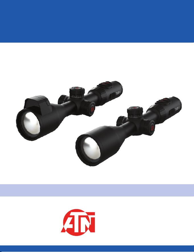
ThOR 6 Series
THERMAL IMAGING SCOPE
MANUAL
AMERICAN
TECHNOLOGIES
NETWORK CORP.

2
Welcome to the ATN Family!
Thank you for choosing the ThOR 6 Elite Thermal Riflescope!
This manual will guide you through the setup, operation, and maintenance
of your device to ensure optimal performance and long service life.
Please read this manual carefully before using the product and retain it
for future reference.
REVISION HISTORY
Version Revision Text Released
V1.0.0 First release November 2025

3
ABOUT THIS MANUAL
• This manual is provided for reference only. Minor differences may
exist between the descriptions in this manual and the actual product.
• We are not liable for any loss or damage resulting from operation of
the product in ways that are not in accordance with this manual.
• The manual may be updated in accordance with the latest laws,
regulations, or product revisions. For detailed or updated
information, please refer to the printed manual, QR code, or our official
website.
• All designs, features, and software are subject to change without
prior notice. Product updates may result in differences between your
device and the information in this document.
• Printing errors or discrepancies in function descriptions,
operations, or technical data may occur. In case of doubt or dispute,
we reserve the right of final interpretation.
• If the PDF version of this manual cannot be opened, please update
your reader software or try another standard PDF reader.
• All trademarks and registered trademarks mentioned in this
manual are the property of their respective owners.
• If any issues occur while using the device, please contact your
supplier, local distributor, or customer service for assistance.
• In the event of any uncertainty or disagreement, the manufacturer
reserves the right of final explanation.

4
TABLE OF CONTENTS
About This Manual ............................. 3
1. Product Introduction ............................ 6
2. Product Overview ...............................6
2.1 Package Contents .......................... 6
2.2 Device Description ..........................7
2.3 Button Description ..........................8
2.4 Specifications ............................ 10
2.5 Mounting the Riflescope .................... 14
3. Device Operation .............................. 15
3.1 Power Supply ............................. 15
3.1.1 Installing the Battery .................... 15
3.1.2 Charging the Device .................... 15
3.2 Controls ................................. 16
3.3 Power On / Off ............................ 16
3.4 Initial Setup .............................. 17
3.5 Image Adjustment ......................... 18
3.5.1 Diopter Adjustment .................... 18
3.5.2 Focus Adjustment ..................... 18
3.5.3 Status Bar Display ..................... 19
3.5.4 Adjusting Brightness ...................20
3.5.5 Adjusting Sharpness ...................20
3.6 Videos Recording and Capturing Images ....... 21
3.6.1 Recording Videos. . . . . . . . . . . . . . . . . . . . . . 21
3.6.2 Capturing Images ..................... 21
4. Configuring the Riflescope ......................22
4.1 Quick Menu ..............................22
4.2 Main Menu ............................... 24
4.2.1 Thermal ............................. 24
4.2.2 Reticles .............................28
4.2.3 Zeroing Profile ........................29

5
4.2.4 Zeroing Setup ........................30
4.2.5 Ballistic Calculator (for LRF models) ....... 31
4.2.6 Optical Ranging Mode (for non-LRF models) 34
4.2.7 Laser Ranging – Measurement Considerations
(for LRF models) ...........................35
4.2.8 Gallery ..............................36
4.2.9 RAV (Recoil Activated Video) ............36
4.2.10 Functionalities .......................37
4.2.11 Settings ............................ 41
5. System Update ................................ 47
5.1 Manual Firmware Update .................... 47
5.2 Firmware Update via Mobile App .............. 48
6. Exporting Files ................................49
7. Important Safety Information ....................50
8. FCC Compliance Statement .....................52
9. Prop 65 warning ...............................53
Proposition 65 Warning for California Consumers .... 53
Export Disclaimer ............................53
10. Warranty and Support Information ............... 54
5-Year Limited Product Warranty ................. 54
Limitation of Liability ..........................54
Product Warranty Registration ..................55
Obtaining Warranty Service .................... 55
6
1. PRODUCT INTRODUCTION
The ThOR 6 Elite Thermal Riflescope provides high-precision thermal
imaging with exceptional clarity and a fast frame rate, ensuring smooth and
accurate target tracking even in dynamic environments.
Designed for continuous operation under all lighting and weather
conditions, the riflescope detects the thermal signatures of objects,
animals, and structures in complete darkness, fog, haze, or intense light —
maintaining optimal situational awareness in every scenario.
The ThOR 6 Elite Thermal Riflescope is available in two configurations:
ThOR 6 LRF model — equipped with an integrated Laser Range Finder
(LRF) for precise distance measurement and enhanced targeting accuracy.
ThOR 6 model — identical in performance, but without the built-in LRF
module.
Built for demanding field applications, the ThOR 6 delivers reliable
performance, advanced image processing, and consistent visual quality
across a wide range of operational environments.
2. PRODUCT OVERVIEW
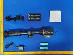
2.1 PACKAGE CONTENTS
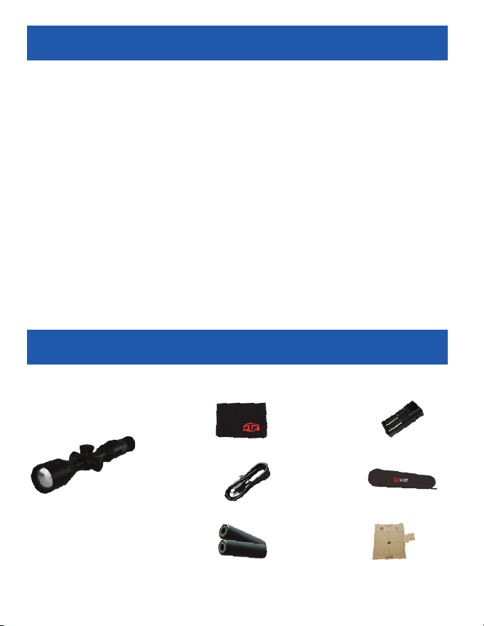
ATN ThOR 6
Thermal Scope
2x18650 rechargeable
batteries
USB Type-C cable
Carrying bag
Battery charger
Lens cloth
Heated target for
zeroing
7
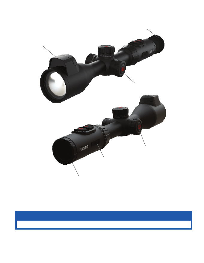
2.2 DEVICE DESCRIPTION
* For ThOR 6 LRF models only.
THIS PRODUCT CONTAINS NATURAL RUBBER LATEX, WHICH MAY CAUSE ALLERGIC REACTIONS
CAUTION!
The instructions in this manual are for informational use only and subject to change without notice.
This manual is not to be construed as a commitment by ATN Corp. ATN Corp. assumes no
responsibility or liability for any errors or inaccuracies that may appear in this book.
©2025 ATN Corp. All rights reserved.
USB TYPE-C PORT
BATTERY COMPARTMENT
DIOPTER ADJUSTMENT RING
FOCUS ADJUSTMENT KNOB
LASER RANGEFINDER*
EYESHADE
8
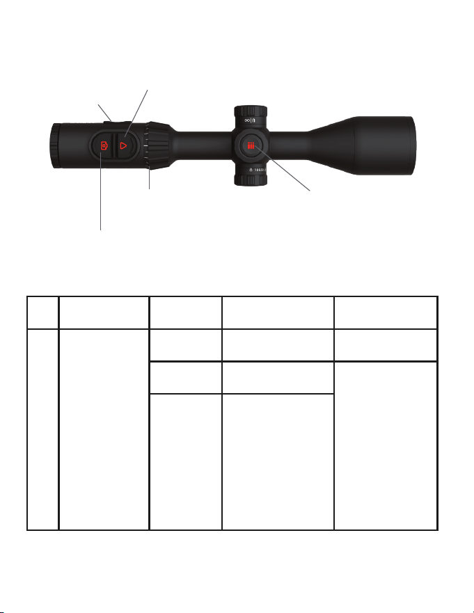
2.3 BUTTON DESCRIPTION
POWER BUTTON
CONTROL WHEEL
ZOOM
CONTROLLER
UP BUTTON
DOWN BUTTON
Table 2.3.1 Button description
No. Button
Current
Status
Short Press Long Press
1
POWER
BUTTON
Powered off ––––
Power on the
device
Home
screen
NUC (Non-Uniformity
Correction)
On the Home
screen, a 3-2-1
countdown prompt
appears:
If the Power button
is released during
the countdown, the
device enters into
Standby mode.
When the count-
down completes,
the device will
power off.
Quick/
Main menu
interface
Return to home
screen /Return to
the previous inter-
face without saving

9
No. Button
Current
Status
Short Press Long Press
2
UP BUTTON
(FOR LRF
MODELS)
Home
screen
LRF Measurement Change Palette
UP BUTTON
(FOR NON-
LRF MODELS)
Change Palette ––––––
3
DOWN BUT-
TON
Home
screen
Take a photo
Start/Stop video
recording
4
CLICK
CONTROL
WHEEL
Home
screen
Enter the Quick
Menu interface
Enter the Main
Menu interface
Quick Menu
interface
Adjust parameters Save and back
Main Menu
interface
Adjust parameters /
Enter the submenu
Save and back
Zeroing/
Pixel
Correction
interface
Switch the move-
ment direction
Save and back
ROTAT E
CONTROL
WHEEL
Home
screen
–––––
Quick menu
interface
Change options and values
Main menu
interface
Change options and values
Zeroing/
Pixel
Correction
interface
Change reticle position
5
ZOOM
CONTROLLER
Home
screen
PIP is ON: zoom PIP image
PIP is OFF: zoom main image
6 FOCUS KNOB ––––– Rotate the focus knob to adjust the image

10
2.4 SPECIFICATIONS
ThOR 6 325 ThOR 6 335 ThOR 6 635 ThOR 6 650
ThOR 6 335
LRF
ThOR 6 635
LRF
ThOR 6 650
LRF
Model
TIWST6325A TIWST6335A TIWST6635A TIWST6650A TIWST6335LRF TIWST6635LRF TIWST6650LRF
Detector Type
12μm VOx Uncooled Focal Plane Array
Sensor Resolution
384×288 384×288 640×512 640×512 384×288 640×512 640×512
Refresh Rate
50 Hz
Thermal Sensitivity
(NETD)
≤15mK
SharpIR©
Yes
Non-Uniformity
Correction (NUC)
Auto / Semi Auto / Manual
Lens System
25 mm
(Ge); F/1.0
35 mm
(Ge); F/1.0
35 mm
(Ge); F/1.0
50 mm
(Ge); F/1.0
35 mm (Ge);
F/1.0
35 mm (Ge);
F/1.0
50 mm (Ge);
F/1.0
Field of View (HxV)
10.53° ×
7.91°
7.53° ×
5.65°
12.52° ×
9.41°
8.78° ×
6.59°
7.53° ×
5.65°
12.52° ×
9.41°
8.78° × 6.59°
Focus Mechanism
Manual, Central Knob Control
Magnification
2.5-20× 3.5-28× 2-16× 3-24× 3.5-28× 2-16× 3-24×
Digital Zoom
1x, 2x, 4x, 8x
Zoom Type
Step & Smooth Zoom
Detection Range
2300 m 2750 m 3100 m 3650 m 2750 m 3100 m 3650 m

11
ThOR 6 325 ThOR 6 335 ThOR 6 635 ThOR 6 650
ThOR 6 335
LRF
ThOR 6 635
LRF
ThOR 6 650
LRF
Display Resolution
0.49” OLED, 1920×1080 Resolution
Eye Relief
50 mm
Diopter Range
-5 to +5 D
Picture-in-Picture
(PIP)
Yes
Reticle Types
10 Styles
Reticle Transparency
Control
Yes
Zeroing Freeze
Yes
Color Palettes
White Hot, Black Hot, Iron Red, Alarm, Green Hot, Sepia
Battery Type
1 × 18650 (Internal) & 1 × 18650 Rechargeable (Replaceable)
Battery Life
~9 hrs
Supports External
Power Supply
Yes, USB Type-C (5 VDC / 2A)
Standby / Sleep
Mode
Yes
Startup Time
<7 seconds (instant from Standby)
Internal Storage
Capacity
64 GB

12
ThOR 6 325 ThOR 6 335 ThOR 6 635 ThOR 6 650
ThOR 6 335
LRF
ThOR 6 635
LRF
ThOR 6 650
LRF
Video / Audio
Recording
Yes
Internal Gallery
Yes
Recoil Activated
Video (RAV)
Yes
Media Output
USB Type-C
Built-in Wi-Fi
(Hotspot)
Yes
App (Apple Store/
Google Play)
Yes (ATN Connect 6 – iOS & Android)
Built-in Laser
Rangefinder (LRF)
– Yes
LRF Range
– 1000 m
LRF Accuracy
– ±1 m
LRF Laser Specs
– 905 nm, Class 1 (Eye Safe)
Ballistic
Calculator
– Yes
Hot Point Tracking
Yes
Geomagnetic +
Gyroscope
Yes

13
ThOR 6 325 ThOR 6 335 ThOR 6 635 ThOR 6 650
ThOR 6 335
LRF
ThOR 6 635
LRF
ThOR 6 650
LRF
Material
Magnesium Alloy
Mounting
30 mm Rings (not included)
Weight
790 g /
1.74 lbs
830 g /
1.83 lbs
830 g /
1.83 lbs
830 g /
1.83 lbs
830 g /
1.83 lbs
855 g /
1.89 lbs
855 g /
1.89 lbs
Dimensions
(L x W x H)
410×85×66
mm/
16.14×3.35×
2.60 in
430×85×72
mm/
16.93×3.35×
2.83 in
430×85×72
mm/
16.93×3.35×
2.83 in
430×85×72
mm/
16.93×3.35×
2.83 in
430×85×72
mm/
6.93×3.35×
2.83 in
430×85×80
mm/
6.93×3.35×
3.15 in
430×85×80
mm/
16.93×3.35×
3.15 in
Max Recoil Rating
6000 Joules / 1000g acceleration over 0.4 ms
Operating
Temperature
-30°C to 55°C (-22°F to 131°F)
Waterproof /
IP Rating
IP67
Actual battery life may vary depending on the frequency of feature usage such as Wi-Fi, video
recording, and other power-consuming functions.
Design and software improvements may be implemented to enhance product performance without
prior notice.
The latest version of this user manual is available for download at: www.atncorp.com

14
2.5 MOUNTING THE RIFLESCOPE
Follow the steps below to correctly mount your ThOR 6 Elite Thermal
Riflescope onto your weapon rail to ensure secure and accurate alignment.
Steps:
1. Prepare the Mount
Use an Allen wrench to unscrew the top part of the mounting ring.
2. Position the Riflescope
Place the riflescope into the bottom half of the mounting ring, ensuring
the screw holes on the top and bottom parts align properly.
3. Secure the Top Screws
Insert and tighten the screws to secure the riflescope within the mounting
ring.
4. Attach to the Rail
Loosen the screws on the lower half of the ring. Place the assembly onto
the rifle’s rail and ensure the scope is level.
5. Final Tightening
Tighten all screws evenly to firmly secure the riflescope to the rail.
NOTE
The mounting ring is sold separately — please refer to the actual
product for compatibility.
NOTE
Ensure both the riflescope base and the rail surface are clean. Use a
lint-free cloth to remove dust or debris before installation.
NOTE
Do not overtighten the screws to avoid damaging the mounting
system or the riflescope body.

15
3. DEVICE OPERATION
3.1 POWER SUPPLY
The riflescope is powered by a dual-battery system — one built-in
rechargeable battery and one removable 18650 battery (included in the
package).
You can also charge the device directly via the USB Type-C port.
NOTE
The riflescope can operate with a single battery, but for extended
operation, it is recommended to use both batteries simultaneously.
3.1.1 INSTALLING THE BATTERY
1. Open the cover of the external battery compartment located on the
right side of the riflescope’s center section.
2. Insert the provided 18650 battery, ensuring it is installed according to
the polarity markings on the device housing.
3. Close and tighten the battery compartment cover securely.
TIP
Use only high-quality, button-top 18650 batteries to ensure proper
contact and avoid power interruptions under recoil.
3.1.2 CHARGING THE DEVICE
You can charge the riflescope through the Type - C por t using the
included data cable.
The battery level indicator is displayed on the status bar when the
device is powered on. Charge the unit promptly when the level is low to
ensure proper operation.
Charging Guidelines:
Maintain a battery temperature between 32°F and 140°F during charging.
Always use the original charging cable supplied with the device.

16
Charging Steps:
Open the rubber cover protecting the Type-C port.
Connect the provided Type-C cable to the port and a power source.
Charging Indicator States:
Red and green flashing alternately – Charging error.
Red light on – Charging in progress.
Green light on – Fully charged.
Light off – Not connected or not charging.
RECOMMENDATION
Fully charge the device before first use and recharge every 3–6
months during long-term storage to maintain battery health.
3.2 CONTROLS
When the riflescope is powered on, press and hold the Control Wheel to
open the main menu.
The functions of the buttons are as follows:
• Rotate the Control Wheel to navigate up or down through the menu.
• Press the Control Wheel to select or confirm a setting.
• Press and hold the Control Wheel or press the Power button to exit
the menu.
3.3 POWER ON / OFF
Power On
Press and hold the Power button until the ATN logo appears on the
display. After startup, remove the lens cover before operation.
Power Off
Press and hold the Power button until the countdown 3-2-1 finishes.
Once the countdown completes, the riflescope will power off automatically.

17
Standby Mode
To enter Standby Mode, press and hold the Power button, then release
it before the countdown 3-2-1 ends.
To wake the riflescope from Standby Mode, short-press the Power
button once.
TIP
If you hold the button until the countdown finishes, the device will
shut down completely.
Releasing it early activates Standby Mode, allowing faster wake-up
and lower power consumption.
3.4 INITIAL SETUP
When starting the riflescope for the first time, or after performing a factory
reset, you will need to set the language, Wi-Fi password, and device time.
Step 1: Power On
Press and hold the Power button to turn on the riflescope. The
Language Selection screen will appear.
Step 2: Set Language
1. Rotate the Control Wheel to highlight your preferred language.
2. Press the Control Wheel to confirm. The Wi-Fi Password screen
will appear.
Step 3: Set Wi-Fi Password
1. Rotate the Control Wheel to select a digit, or choose Skip to use the
default password “12345678.”
2. Press the Control Wheel to confirm the selection.
3. Rotate again to adjust the value, then press to save. Repeat steps 1–3
for each digit of the password. Once complete, select Next and press
the Control Wheel.
Step 4: Set Device Time
1. Rotate the Control Wheel to select the time field (hours, minutes,
seconds).
18
2. Press to confirm, then rotate to adjust. Repeat for each field. Once
done, select Next and press the Control Wheel.
The main viewing screen will appear, and the riflescope is ready for use.
3.5 IMAGE ADJUSTMENT
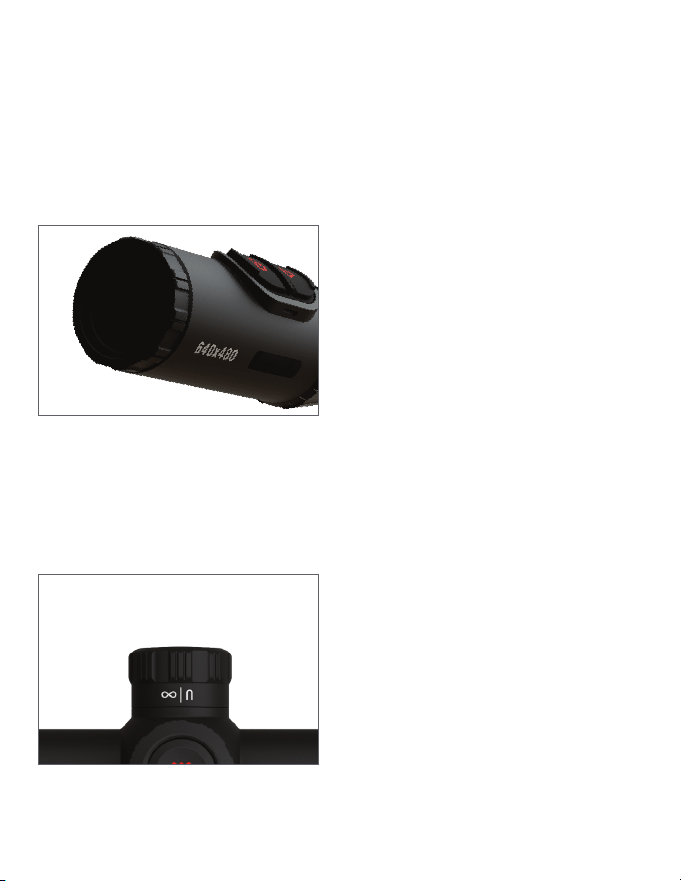
3.5.1 DIOPTER ADJUSTMENT
To achieve a sharp and comfortable
view, adjust the diopter ring
according to your eyesight. It is
recommended to perform this
adjustment before configuring other
settings.
Steps:
1. Aim the riflescope at a well-lit
target or a clear background.
2. Look through the eyepiece
and slowly rotate the diopter adjustment ring clockwise or
counterclockwise until the on-screen icons and image appear sharp
and clear.
3.5.2 FOCUS ADJUSTMENT
Manually rotate the Focus knob to
achieve a clear image of the target.
Steps:
1. Aim the riflescope at your target.
2. Rotate the Focus knob clockwise
or counterclockwise until the image
becomes crisp and well-defined.
19
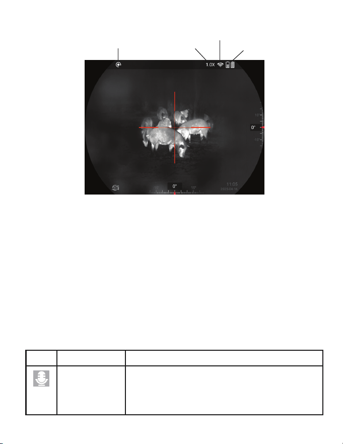
3.5.3 STATUS BAR DISPLAY
The Status Bar provides real-time information such as battery level,
zoom, and connection status.
To enable or disable the status bar:
1. Press and hold the Control Wheel to open the Main Menu.
2. Rotate the wheel to navigate to Settings → Status Bar.
3. Press the Control Wheel to toggle the Status Bar On or Off.
4. The status bar will now appear (or disappear) on the display.
TIP
Keeping the status bar enabled ensures you can monitor key system
parameters during operation.
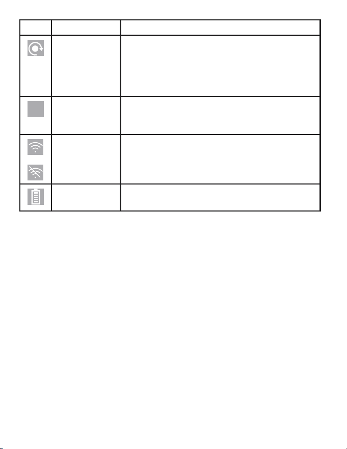
Table 3.5.3 Description of status bar
Icon Name Description
Record Audio • The microphone is active — videos will be
recorded with sound.
• The microphone is turned off — videos will
be recorded without sound.
RAV
ZOOM
WI-FI
BATTERY LEVEL
20
Icon Name Description
RAV • When RAV is enabled, the riflescope auto-
matically starts video recording once the im-
pact sensor detects a shot.
• When RAV is disabled, the riflescope will not
start recording automatically.
1.0 x
Digital Zoom Supports multiple levels of digital zoom.
The available zoom magnification may vary de-
pending on the model.
Wi-Fi • The Wi-Fi module is active — the device can
connect to a smartphone or other devices.
• Wi-Fi is turned off — wireless connection is
unavailable.
Battery level Displays the current battery charge level in real
time.
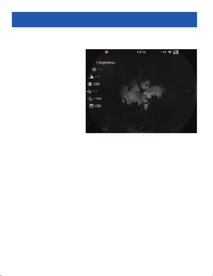
3.5.4 ADJUSTING BRIGHTNESS
Adjusts the overall display brightness. Increasing the level makes the
image appear brighter.
To adjust brightness:
1. Press the Control Wheel to open the Quick Menu.
2. Rotate the Control Wheel to select Brightness.
3. Press the Control Wheel to confirm.
4. Rotate the Control Wheel to increase or decrease brightness.
TIP
Higher brightness levels improve visibility in daylight, while lower
levels are recommended for night operations.
3.5.5 ADJUSTING SHARPNESS
Controls the clarity of object edges in the image. Higher sharpness levels
make contours appear more defined.

21
To adjust sharpness:
1. Press the Control Wheel to open the Quick Menu.
2. Rotate the Control Wheel to select Sharpness.
3. Press the Control Wheel to confirm.
4. Rotate the Control Wheel to increase or decrease sharpness.
TIP
A moderate sharpness level provides a natural and balanced image.
3.6 VIDEOS RECORDING AND CAPTURING
IMAGES
3.6.1 RECORDING VIDEOS
To manually record a video, follow these steps:
1. On the viewing screen, press and hold the Down button for 3
seconds to start recording.
• The recording icon will flash on the screen.
• The recording timer will appear, showing the elapsed time.
2. To stop recording, press and hold the Down button again for 3
seconds.
• The recording icon will disappear.
• The video camera icon with a check mark will display briefly on screen.
TIP
Make sure you have enough storage space before recording long
videos.
3.6.2 CAPTURING IMAGES
To take a still image:
1. Press the Down button once.
2. When the image is successfully saved, a camera icon will appear
briefly on the screen.
NOTE
Images are automatically saved in the Gallery and can be viewed or
exported later through the Type-C connection.
22
4. CONFIGURING THE RIFLESCOPE
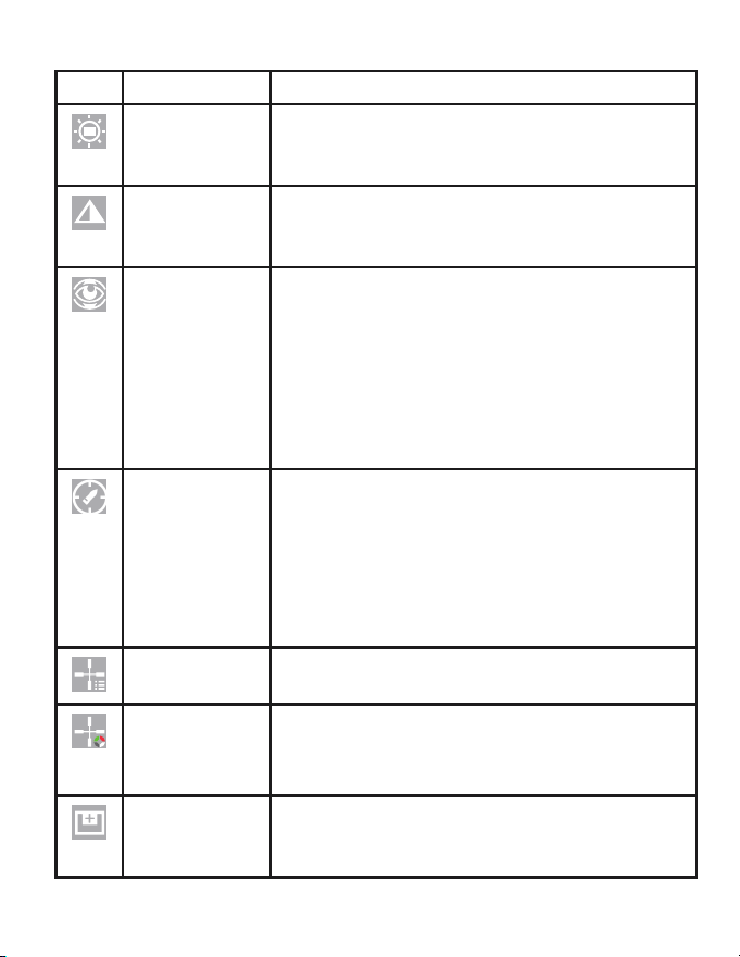
4.1 QUICK MENU
The Quick Menu
provides fast access to the
most commonly used image
settings, allowing you to
adjust the display without
entering the full system
menu.
You can quickly modify
Brightness, Sharpness,
SharpIR, Ballistic
Calculator (for LRF
models), Reticle Type,
Reticle Color (for non-LRF
models), PIP.
To access and use the Quick Menu:
1. Press the Control Wheel to open the Quick Menu.
2. Rotate the Control Wheel to highlight the parameter you wish to adjust.
3. Press the Control Wheel to confirm and modify the selected parameter.
4. Rotate the Control Wheel again to fine-tune the value.
5. Press and hold the Control Wheel to exit and save the configuration.
TIP
The Quick Menu is designed for rapid adjustments in the field—ideal
when lighting or environmental conditions change suddenly.
23
Table 4.1 Quick menu
Icon Name Description
Brightness
Adjusts the overall screen brightness. Increasing
brightness helps in daylight, while lowering it
improves visibility at night.
Sharpness Controls the clarity of image edges. Higher
sharpness enhances detail, while lower settings
make the image smoother.
SharpIR Powered by ATN’s proprietary SharpIR© tech-
nology, the device uses advanced AI-driven
algorithms to enhance image sharpness and
clarity in real time.
This intelligent processing dynamically refines
edge definition and contrast, making it easier
to distinguish heat signatures in cluttered or
low-visibility environments.
Ballistic
Calculator
(for LRF
models)
Activating Ballistic Calculator enables automatic
bullet drop compensation based on your ballis-
tic profile and environmental data. When turned
On, an additional POI reticle appears, indicating
the adjusted point of impact according to ballistic
calculations. When Off, the riflescope operates
in standard mode without ballistic correction.
Reticle Type Allows you to select the reticle style that best
suits your shooting or observation needs.
Reticle Color
(for non-LRF
models)
Changes the color of the reticle for better visibil-
ity against different backgrounds.
PIP (Picture
-in-Picture)
Enables a small magnified view of the central
area on the screen, helping with precise aiming
while maintaining full field awareness.

24
4.2 MAIN MENU
The Main Menu provides access to all advanced configuration options
of the riflescope.
Press and hold the Control Wheel to open the Main Menu. Rotate the
Control Wheel to navigate through the categories and press it to enter a
selected item.
MAIN MENU STRUCTURE
1. Thermal
2. Reticles
3. Zeroing Profile
4. Zeroing Setup
5. Ballistic Calculator (for LRF models)
6. Ranging (for non-LRF models)
7. Gallery
8. RAV
9. Functionalities
10. Settings
4.2.1 THERMAL
This section allows you to adjust key image parameters to achieve the
best thermal performance under different environmental conditions.
Use it to fine-tune brightness, contrast, sharpness, and color palettes for
optimal image clarity, detail, and target detection.
Table 4.2.1 Thermal menu
Icon Name Description
Brightness Adjusts the overall screen brightness.
Increasing brightness helps in daylight, while
lowering it improves visibility at night.
Contrast Adjusts the difference between warm and cold are-
as to enhance image depth and object separation.
25
Icon Name Description
Sharpness Controls the clarity of image edges. Higher
sharpness enhances detail, while lower settings
make the image smoother.
SharpIR Enables or disables the SharpIR™ image en-
hancement algorithm. When enabled, it im-
proves image definition and object contrast.
Palette Selects the thermal color scheme used to repre-
sent temperature variations on the display.
Available Color Palettes:
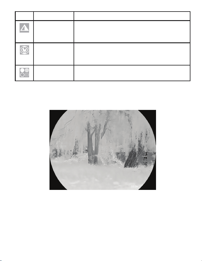
White Hot: Hotter objects appear white. The higher the temperature, the
brighter the image.
26
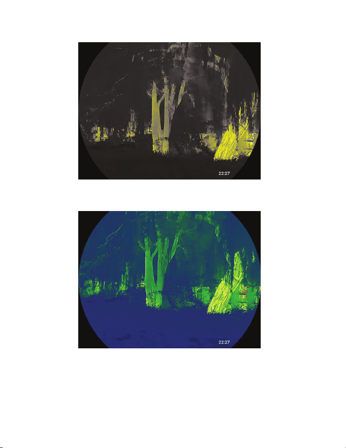
Sepia: Hotter objects appear amber. Higher temperatures produce
brighter tones.
Green Hot: Hotter objects appear green. Brighter green indicates higher
heat.
27
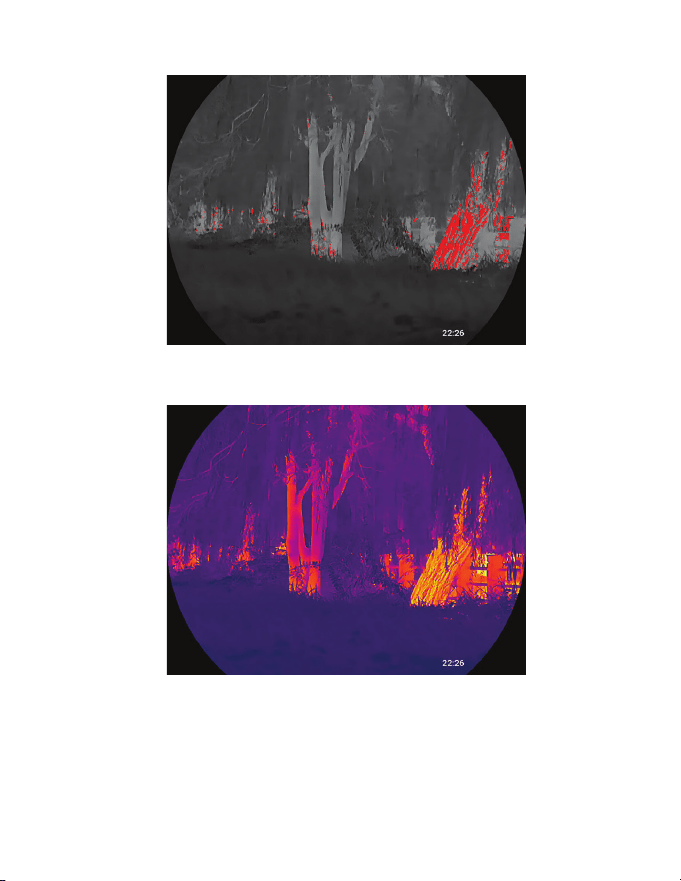
Alarm: Hot objects appear red for quick visual detection.
Iron Red: Hotter objects appear in red or orange tones.
28
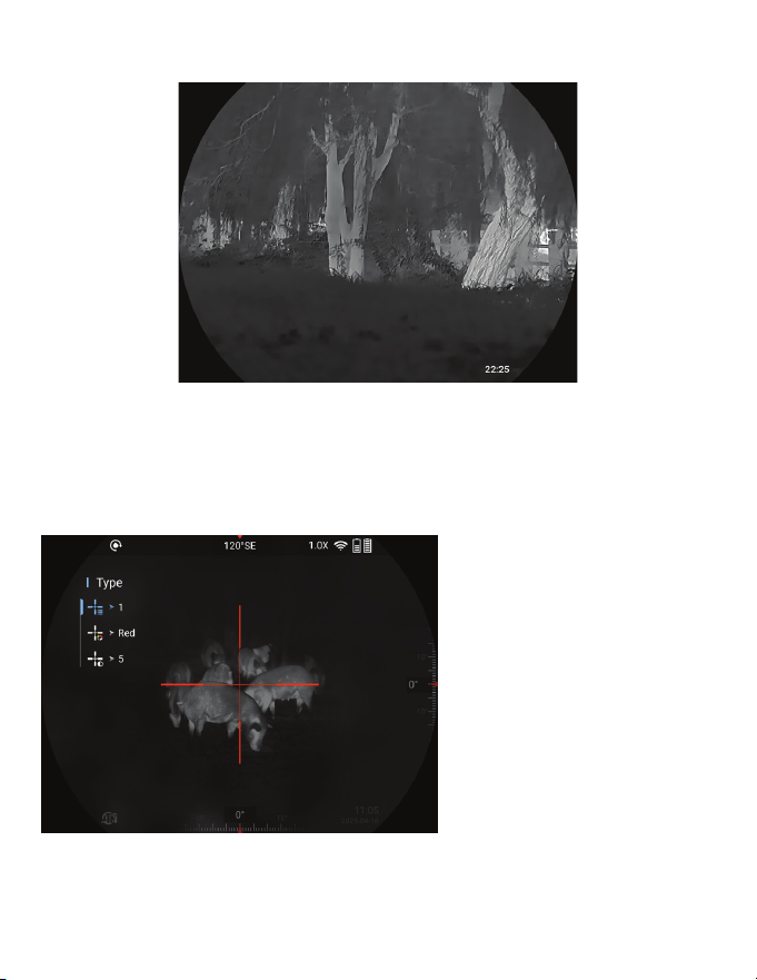
Black Hot: Hotter objects appear darker; colder areas are lighter.
TIP
Choose the palette that provides the best contrast for your
environment or preference.
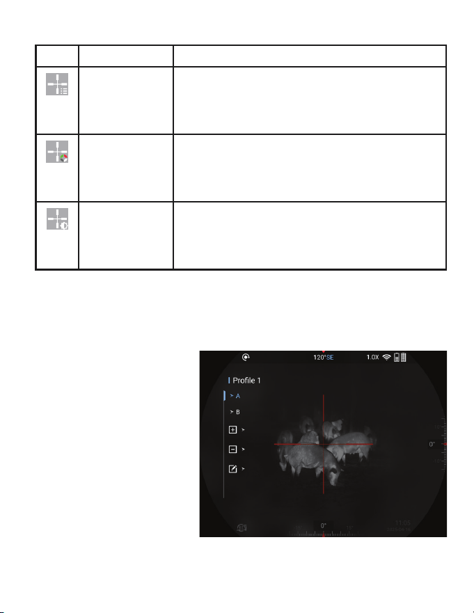
4.2.2 RETICLES
This section allows you
to customize the aiming
reticle according to your
shooting preferences and
environmental conditions.
You can adjust the reticle
type, color, and transparency
to achieve the best visibility
and precision under different
lighting and background
conditions.
29
Table 4.2.2 Reticle menu
Icon Name Description
Reticle Type Choose from multiple reticle designs to match
your shooting style and preferences. Different
types provide better visibility and alignment for
various distances and conditions.
Reticle Color Adjust the reticle color to ensure optimal con-
trast and visibility against different backgrounds
and lighting environments. This helps maintain
accuracy in diverse field conditions.
Transparency Control the reticle’s opacity to achieve a comfort-
able balance between visibility and target clarity,
ensuring that the reticle remains clear without
obscuring the target image.
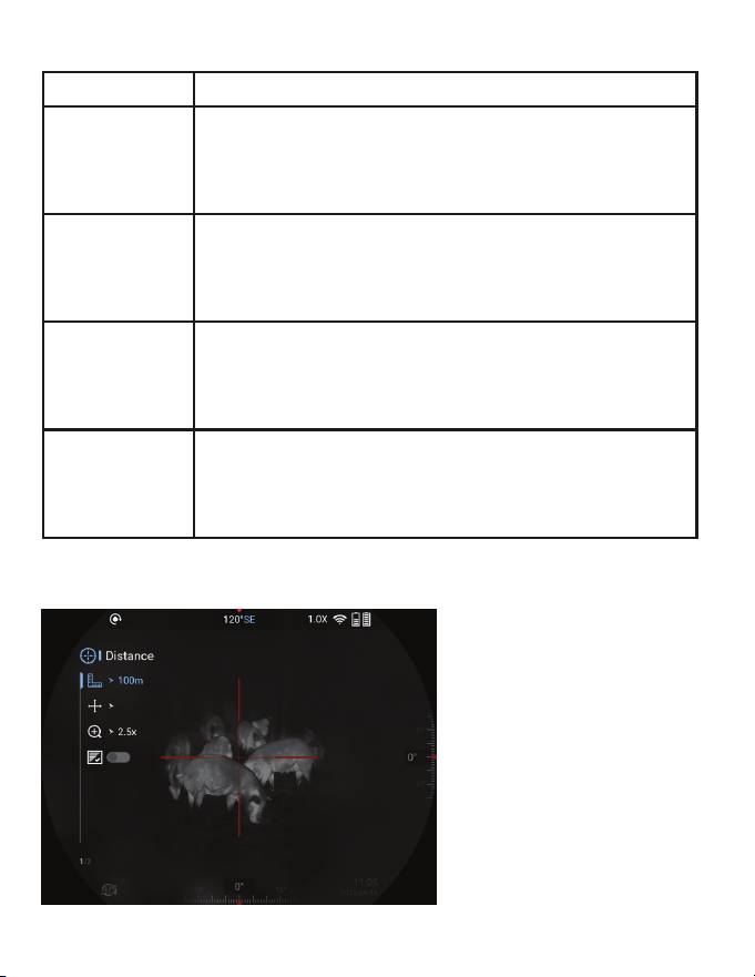
4.2.3 ZEROING PROFILE
This menu displays all
existing zeroing profiles and
allows basic management
functions. You can create
new profiles, rename them,
or delete unnecessary
ones.
30
Table 4.2.3 Zeroing Profile menu
Name Description
List of
Profiles
Displays the list of available zeroing profiles stored in
the device. Each profile can contain a unique zeroing
configuration, allowing you to maintain different setups for
various rifles, ammunition types, or shooting distances.
Add Profile
Create a new zeroing profile. This allows you to store
additional zeroing configurations without overwriting
existing ones. Each newly added profile can later be
customized and renamed for easier recognition.
Delete Profile
Delete the selected zeroing profile from the list. Use this
function to remove outdated or unnecessary profiles and
keep your list organized. A confirmation prompt will appear
before deletion to prevent accidental data loss.
Rename
Profile
Rename the selected profile to a custom label that reflects
its use — for example, the rifle model, ammunition type, or
specific zeroing distance. Custom names make it easier to
identify and switch between profiles in the field.
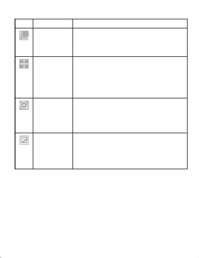
4.2.4 ZEROING SETUP
The Zeroing Setup section
allows you to precisely align
the riflescope’s reticle with
the point of impact for each
saved profile.
From this menu, you can
select the shooting distance,
fine-tune reticle position,
adjust zoom, and use the
freeze-frame function for
accurate one-shot zeroing.
31
Table 4.2.4 Zeroing Setup menu
Icon Name Description
Distance
Select the target distance at which you are
performing zeroing. Use the Control Wheel
to choose a distance value according to your
shooting setup.
Position
Adjustment
Adjust the position of the reticle along the X
(horizontal) and Y (vertical) axes to align the point
of aim with the actual point of impact. After firing a
shot, rotate the Control Wheel to move the reticle
to the bullet impact position. Press and hold the
Control Wheel to confirm and save the adjustment.
Zoom
Change the magnification level during the zeroing
process for greater precision when aligning the
reticle with the impact point. Rotate the Control
Wheel to zoom in for fine adjustments or zoom out
for a wider field of view.
Freeze Frame
Capture a still frame of the current image to
simplify zeroing.
After firing, activate Freeze Frame to lock the display
image, then adjust the reticle without worrying
about target movement or heat dissipation.
4.2.5 BALLISTIC CALCULATOR (FOR LRF MODELS)
Before configuring Ballistic Calculator, complete the zeroing procedure
for the selected profile (see 4.2.4 Zeroing Setup).
The Ballistic Calculator feature computes the bullet’s point of impact
using stored ballistic parameters, environmental data, and the selected
zeroing profile. Enable it to get aim corrections automatically for a given
range.
To enable and configure Ballistic Calculator
1. Press and hold the Control Wheel to open the Main Menu.

32
2. Rotate the Control Wheel to highlight the Ballistic Calculator and
press the Control Wheel to Enable / Disable the function:
• On: the riflescope will calculate aim corrections automatically
using the parameters below.
• Off: no automatic ballistic corrections will be computed.
3. To set ballistic parameters, rotate to Parameters and press the
Control Wheel to open the configuration screen. Then:
• Rotate the Control Wheel to select a parameter.
• Press the Control Wheel to edit.
• Rotate to change the value and press to save.
• Repeat for each parameter required.
4. Press and hold the Control Wheel to save all changes and exit.
Ballistic Parameters and their description:
Parameter Description / How to obtain
Zeroing Profile The zeroing profile currently selected (from
Zeroing Profile).
Zeroing Range The distance saved in the profile for which
the zero was performed.
Ballistic Coefficient (BC) Enter the bullet’s BC from the ammunition
manufacturer (package or datasheet).
Ballistic Type Select the ballistic model/type (if applicable)
used by the rifle/ammo.
Ballistic Weight Bullet mass (typically in grains). Enter the
value from ammo specs.
Init Velocity Muzzle velocity (m/s or ft/s) — measured or
provided by the ammo manufacturer.
Sight Height Vertical distance between the bore axis and
the riflescope optical axis (mm or inches).

33
Parameter Description / How to obtain
Altitude Shooting site elevation above sea level
(meters or feet).
Temperature Air temperature at the shooting location (°C
or °F).
Air Pressure Current barometric pressure (hPa / mbar or
inHg).
Humidity Relative humidity (%) at the shooting site.
Wind Speed Wind speed (m/s, km/h or mph) used for
drift calculation.
Wind Direction Wind direction relative to shooting azimuth
(e.g., 0° = headwind, 90° = right).
NOTE
Enter environmental parameters as accurately as possible to
improve calculation accuracy. Units follow the device Units setting;
ensure consistency.
Save & Exit
After configuring all required fields, press and hold the Control Wheel
to save the configuration. Confirm when prompted.
TIPS
• Confirm zeroing and ballistic parameters under real conditions
(test fire) and adjust values if required.
• If you change ammunition, create or update a zeroing profile and
ballistic parameters for the new load.
• For field use, enable automatic sensors (if available) to populate
temperature, pressure, and humidity automatically.
34
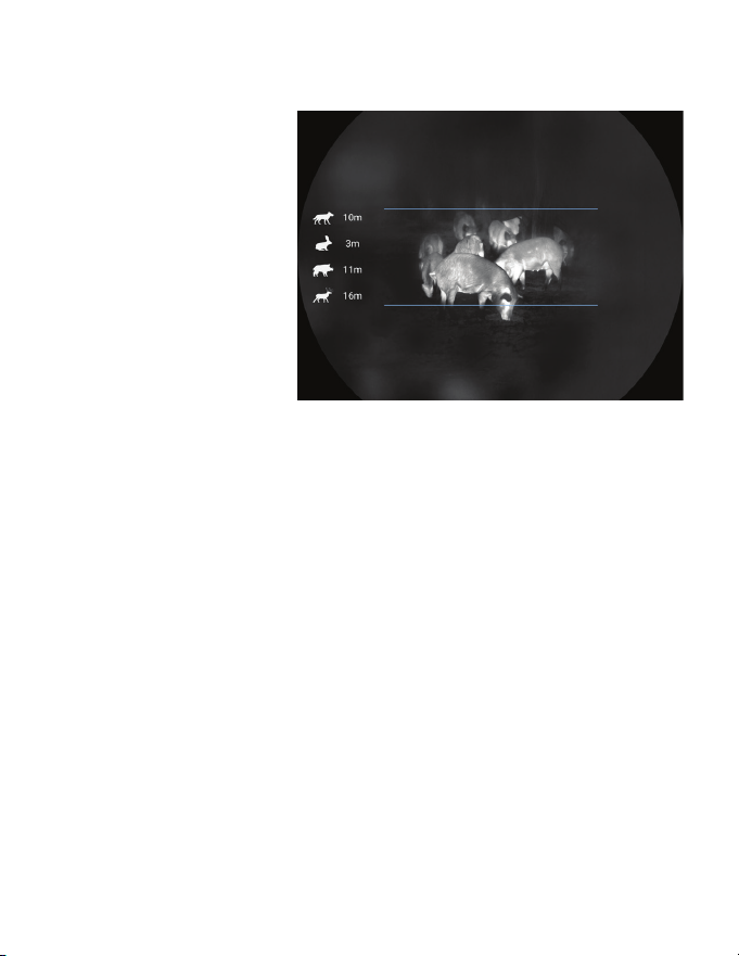
4.2.6 OPTICAL RANGING MODE (FOR NON-LRF
MODELS)
This feature allows
manual range estimation
using the reticle’s reference
marks or on-screen scale.
It is available only on
riflescope models that
do not include a built-in
Laser Range Finder (LRF).
For LRF-equipped
models, see Laser Ranging
Mode.
The optical ranging mode
estimates the distance to
the target by adjusting two horizontal reference lines so that they align with
the top and bottom of the target’s silhouette.
The system then calculates and displays the approximate distance
based on the selected target type and apparent size.
Steps
1. Press and hold the Control Wheel to open the Main Menu.
2. Rotate the Control Wheel to highlight Ranging and press to open it.
3. Rotate the Control Wheel to move the blue lines until they touch the
top and bottom edges of the target.
Once aligned, the system will display the estimated distance between the
target and the riflescope.
NOTE
The accuracy of optical ranging depends on the steadiness of the
device and the size assumptions of the selected animal profile. For
higher precision, use models equipped with the integrated LRF.

35
4.2.7 LASER RANGING – MEASUREMENT
CONSIDERATIONS (FOR LRF MODELS)
The Laser Range Finder (LRF) measures the distance between the
riflescope and a target by detecting the reflected laser beam.
For optimal accuracy and performance, several environmental and
physical factors must be considered.
Suitable Measurement Targets
The LRF is designed to measure distances to targets with different levels
of surface reflectivity:
• High Reflectivity: Road signs, metal surfaces, or bright reflective panels.
• Medium Reflectivity: Building walls, rocks, or painted surfaces.
• Low Reflectivity: Trees, utility poles, animals, or dark matte objects.
NOTE
Targets with extremely low reflectivity (e.g., water, glass, or shiny
black surfaces) may not return a measurable signal.
Factors Affecting Ranging Accuracy
• Target Reflectivity:
The higher the reflectivity, the greater the effective measurement
distance.
• Target Shape and Size:
Small, narrow, or irregularly shaped objects provide less reflected
laser energy, reducing accuracy and range.
• Measurement Angle:
Accuracy is highest when the target surface is perpendicular to the
laser beam.
At steep angles, reflection is weakened, causing potential
measurement errors or loss of reading.
• Environmental Conditions:
Atmospheric factors such as fog, rain, snow, smoke, haze, or direct
sunlight can scatter or absorb the laser signal, reducing range
performance.

36
Optimal Conditions for Accurate Measurement
• Target with medium reflectivity (e.g., wall).
• Target surface perpendicular to the laser beam.
• Weather conditions: Clear skies, without direct sunlight or heavy
atmospheric interference.
TIP
For consistent accuracy, avoid aiming at water, glass, or moving objects,
and perform measurements under stable environmental conditions.
4.2.8 GALLERY
All photos and videos captured on the riflescope are automatically stored
in the internal memory.
You can access and review them directly from the device through the
Gallery menu.
Steps
1. Press and hold the Control Wheel to open the Main Menu.
2. Rotate the Control Wheel to select Gallery, then press to open it.
3. Browse and view content:
• Rotate the Control Wheel to scroll through the list of saved images
and videos.
• Press the Control Wheel to open and play the selected file.
TIP
Long-press the Control Wheel to exit the Gallery and return to the
Main Menu.
4.2.9 RAV (RECOIL ACTIVATED VIDEO)
The RAV function automatically starts video recording when the
riflescope detects recoil from a shot.
This ensures you never miss a key moment without needing to manually
press record.
37
Steps
1. Press and hold the Control Wheel to open the Main Menu.
2. Rotate the Control Wheel to select RAV.
3. Press the Control Wheel to toggle the feature:
• On — The riflescope will automatically record when recoil is detected.
• Off — Recording will only occur manually when the user presses
the record button.
TIP
Ensure the device is securely mounted to detect recoil accurately.
NOTE
The RAV function may not trigger with low-recoil calibers or when
using suppressors.
4.2.10 FUNCTIONALITIES
The Functionalities menu provides access to additional tools and features
that enhance the operation and user experience of your riflescope.
These options allow you to customize interface elements, enable useful
widgets, and optimize the device for different field conditions.
Table 4.2.10 Functionalities menu
Icon Name Description
Zoom
Step
Defines the increment used when changing digital zoom
levels. Smaller steps allow for smoother, more precise
adjustments, while larger steps enable faster zoom
changes.
38
Icon Name Description
Laser
Ranging
The LRF Mode defines how the Laser Range Find-
er operates when measuring distances to a target. To
ensure accurate readings, always keep the riflescope
steady and avoid aiming at reflective or uneven sur-
faces.
• Single Measurement:
In this mode, the riflescope emits a single laser
pulse when you press the Laser button. It meas-
ures the distance once and displays the result on
the screen. Ideal for quick, one-time measure-
ments on stationary targets.
• Continuous Measurement:
The riflescope continuously measures the distance
to the target for a set duration (15, 30, or 60 sec-
onds), updating the display in real time.
This mode is useful for tracking moving targets or
when scanning across varied terrain.
NOTE
Laser radiation can cause eye injury. Never look
directly into the beam or observe it through
optical devices.
Compass When the compass feature is active, the current
heading is displayed at the top of the screen.
Сompass calibration:
To begin compass calibration, rotate the riflescope
along all three axes within 20 seconds, ensuring
each axis completes at least one full 360° rotation.
Once the rotation phase is complete, the device will
display a pop-up prompting you to point the rifle-
scope north. After aligning the device and confirming
the north direction, the calibration process will final-
ize, and the system will return to the main menu.
39
Icon Name Description
Burning
Warning
When the system detects a potential overheating risk
for the sensor, a warning message will appear on the
screen and the shutter will automatically close to pre-
vent damage.
RECOMMENDATION
Avoid aiming at extremely hot objects for long
durations.
Pitch &
Roll
Displays device tilt and inclination relative to the hori-
zon. These indicators help maintain proper leveling of
the riflescope, improving long-range shot consistency.
TIP
Use this feature to ensure accurate zeroing and
stability when shooting from uneven terrain.
PIP Displays a magnified section of the thermal image in
a small window while keeping the full scene visible.
Enhances target precision without losing situational
awareness.
Hot Point Highlights the hottest object detected in the field of
view with a small marker. Useful for quickly locat-
ing heat sources such as game, vehicles, or human
presence.
NOTE
The marker dynamically updates as the scene
changes.
For more details, see “4.2.10.2 Hot Point
Tracking”.
40
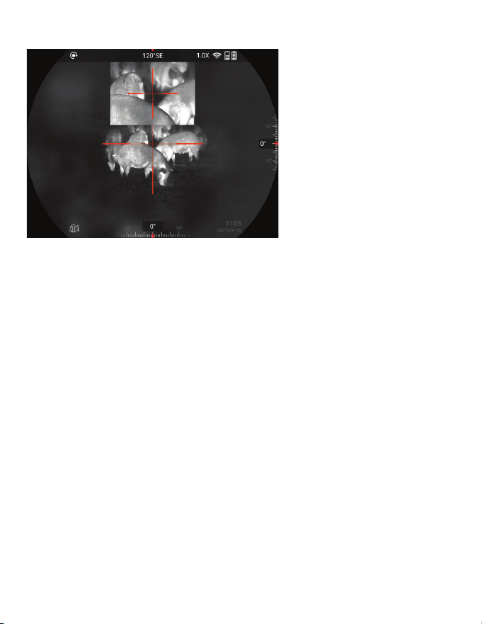
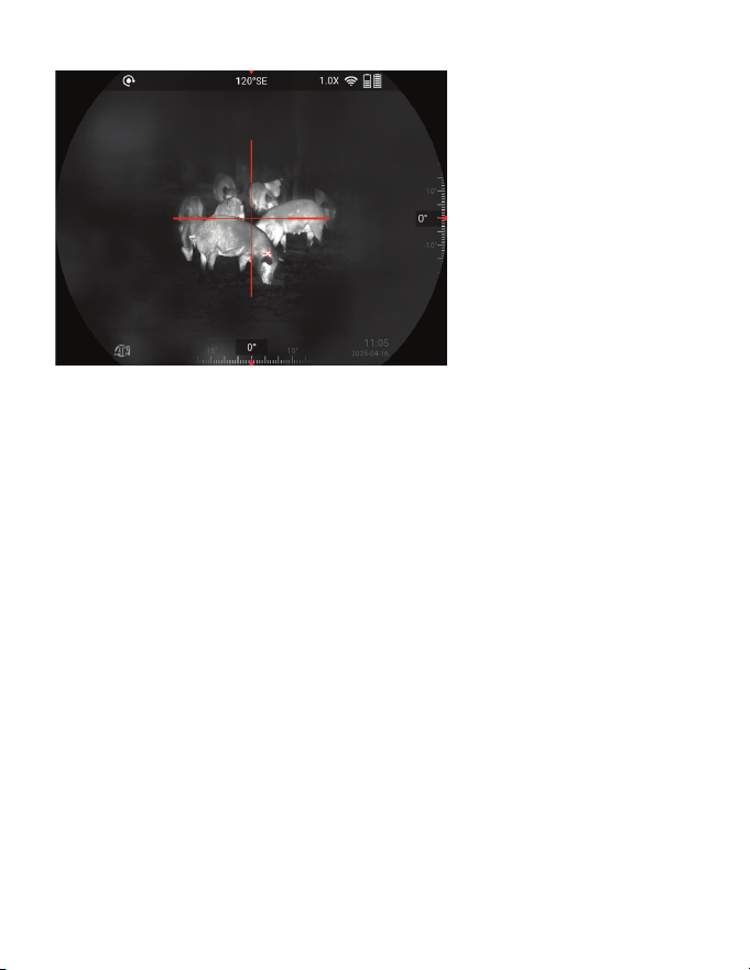
4.2.10.1 PIP (PICTURE-IN-PICTURE) MODE
The PIP (Picture-in-
Picture) mode allows you
to view a magnified portion
of the thermal image in
a smaller window while
maintaining a wide field of
view on the main screen.
This helps with precise
aiming or observation
without losing situational
awareness.
Steps:
1. Press and hold the Control Wheel to open the main menu.
2. Rotate the Control Wheel to select Functionalities -> PIP.
3. Press the Control Wheel to enable or disable PIP mode.
When enabled, a zoomed-in window of the image center will appear at
the top center of the screen.
TIP
• Use PIP mode for accurate long-distance aiming while
maintaining visibility of your surroundings.
• PIP settings can also be quickly accessed through the Quick
Menu.
41
4.2.10.2 HOT POINT TRACKING
The Hot Point function
automatically detects and
marks the hottest object
in the visible area, making
it easier to identify heat
sources in real time.
Steps:
1. Press and hold the
Control Wheel to open the
main menu.
2. Rotate the Control
Wheel to select
Functionalities -> Hot Point.
3. Press the Control Wheel to enable or disable the function.
When enabled, a small hot point icon will appear on the screen,
continuously tracking the area with the highest temperature.
NOTE
The Hot Point feature is most effective in stable environments and
may fluctuate in scenes with multiple strong heat sources.
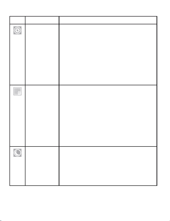
4.2.11 SETTINGS
The Settings menu allows you to configure core system parameters,
manage power options, and adjust device behavior to match your personal
preferences and operational needs.
42
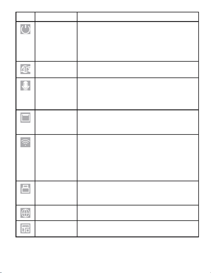
Table 4.2.11 Settings menu
Icon Name Description
NUC
Corrects temperature drift and sensor noise to
maintain image quality.
• Auto: The system performs NUC
automatically when needed.
• Semi-Auto: NUC can be triggered manually
or occurs occasionally.
• Manual: The user can initiate NUC anytime
from the menu or by pressing the assigned
button.
For more details, see “4.2.11.1 Setting NUC”.
Pixel
Correction
Fixes defective (stuck or dead) pixels on the
thermal sensor.
• Auto: The device automatically detects and
corrects bad pixels after user confirmation.
• Manual: Opens the manual correction menu
where you can individually mark and correct
defective pixels.
• Restore: Restores the default pixel map.
For more details, see “4.2.11.2 Setting Pixel
Correction”.
Sleep Mode Sets the period of inactivity after which the
riflescope enters low-power standby mode.
Options: Off, 1 min, 3 mins, 5 mins, 10 mins.
NOTE
Press any button to wake the device from
sleep.
43
Icon Name Description
Shutdown Specifies the duration of inactivity before the
riflescope powers off automatically.
Options: Off, 5 mins, 10 mins, 30 mins, 60 mins.
Use this feature to conserve battery power
during extended downtime.
Logo When enabled, the logo appears in the lower-
left corner of the screen.
Record Audio Press the wheel to enable or disable audio
recording.
• On: Videos are recorded with sound.
• Off: Videos are recorded without sound.
Status Bar Press the Control Wheel to show or hide the
status bar at the top of the screen.
For more details, see “3.5.3 Status Bar Display”
Wi-Fi • Wi-Fi: Turns the wireless connection On/Off
for mobile app pairing or file transfer.
• Wi-Fi Password: Displays the SSID and
current password in an information window.
For more details, see “4.2.11.3 Wi-Fi
Connection Setup”
USB Mode • ON: The riflescope will function as a storage
device for file transfer.
• OFF: The USB port will only charge the device.
Language Select your preferred interface language.
Units Switch between Metric and Imperial
measurement systems.
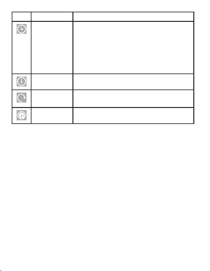
44
Icon Name Description
Time Settings • Time Display: Enable or disable on-screen
time display.
• Time Format: Choose the preferred date/
time format.
• Date & Time: Manually set the current date
and time using the Control Wheel to adjust
each value.
Device Info Device Information page, displaying firmware
version, serial number, and other system data.
Restore
Default
Resets all menu parameters and user
configurations to their factory defaults.
Format Deletes all images and videos stored in the
device memory.
4.2.11.1 SETTING NUC (NON-UNIFORMITY CORRECTION)
NUC (Non-Uniformity Correction), is used to optimize the thermal
image by compensating for small temperature variations across the sensor.
This process ensures uniformity and helps detect even subtle temperature
changes more accurately.
Procedure
1. Press and hold the Control Wheel to open the Main Menu.
2. Rotate the Control Wheel to select Settings → NUC.
3. Press the Control Wheel to access the NUC configuration screen.
Modes
• Auto:
The riflescope performs automatic flat-field calibration at regular
intervals. This helps maintain consistent image quality during long
observation periods.

45
• Semi-Auto:
Press the Power button on the viewing screen to manually trigger
calibration at any time. Recommended when the image appears
slightly uneven or blurry.
• Manual:
Close the lens cap, then press the Power button to manually perform
calibration. This is useful for precise control or when environmental
conditions (e.g., rapid temperature changes) affect image stability.
TIP
Regularly performing NUC ensures the best image uniformity and
helps eliminate fixed-pattern noise, especially after large temperature
fluctuations.
4.2.11.2 SETTING PIXEL CORRECTION
The Pixel Correction function allows you to fix defective (hot, dead, or
stuck) pixels on the thermal sensor to maintain a clean, high-quality image.
Procedure
1. Press and hold the Control Wheel to open the Main Menu.
2. Rotate the Control Wheel to select Settings → Pixel Correction.
3. Press the Control Wheel to open the Pixel Correction configuration
screen.
Modes
• Auto:
The riflescope automatically detects and corrects defective pixels.
1. Select Auto.
2. Follow on-screen instructions to close the lens cap.
3. Rotate the Control Wheel to select Confirm, then press the Control
Wheel to begin correction.
• Manual:
Allows you to manually locate and correct defective pixels.
1. Press the Control Wheel to select X-axis and Y-axis.
46
2. Rotate the Control Wheel to move the cursor over the defective
pixel.
3. Double-press the Control Wheel to save the correction. The center
of the cursor marks the corrected pixel.
• Restore:
Restores the pixel correction map to its factory default state.
A confirmation message appears once the reset is complete.
TIP
Run Pixel Correction if you notice fixed bright or dark points that do
not move with the image — this will recalibrate your thermal sensor for
optimal image quality.
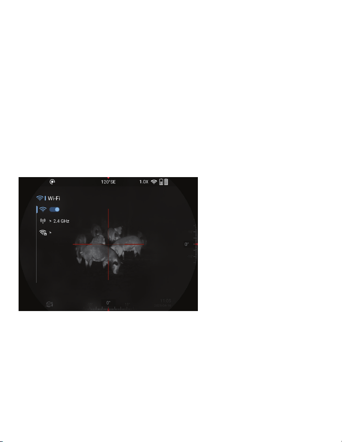
4.2.11.3 WI-FI CONNECTION SETUP
After enabling Wi-Fi,
the riflescope creates its
own wireless hotspot,
allowing you to connect a
smartphone or tablet and
access live view, media
files, or control features
through the ATN mobile app.
Connection Procedure
1. On your smartphone,
open the App Store (iOS) or
Google Play (Android) and
search for “ATN Connect 6”
to download and install the application.
2. Press and hold the Control Wheel to open the Main Menu.
3. Rotate the Control Wheel to select Settings > Wi-Fi, then press the
Control Wheel to enter.
4. Enable Wi-Fi. The device will broadcast its hotspot with the following
credentials:

47
• Wi-Fi Name (SSID): You can find it on the label attached to the
lens cap, or by navigating to Main Menu → Settings → Wi-Fi
Password.
• Password: The password you created during the initial setup. If
you skipped that step, the default password is 12345678. (See “3.4
Initial Setup” for details.).
5. Then launch the ATN Connect 6, choose the device, and follow the
on-screen prompts.
NOTE
The Wi-Fi password can also be changed directly through the ATN
Connect 6 mobile app in the Settings section.
5. SYSTEM UPDATE
You can update the riflescope firmware manually using a USB
connection.
NOTE
Always ensure the device battery level is above 30% before starting
the update. If the charge is below this level, the update will be blocked
and a notification will appear prompting you to recharge the device.
5.1 MANUAL FIRMWARE UPDATE
Follow these steps to update the firmware manually:
1. Download the latest firmware file from the official ATN website.
2. Copy the firmware file (.bin) to the root directory of the riflescope’s
internal storage.
3. Disconnect the device safely from the computer.
4. Reboot the device.
5. When a new firmware version is detected, a message will appear:
“A newer firmware version has been found. Update now?”
6. Confirm by selecting OK with the Control Wheel.
7. The update process will begin automatically.

48
NOTE
During Update: Do not power off or disconnect the device. The
process may take several minutes.
If the installed firmware is already the latest version, a message will
appear:
“The device is already up to date.”
If the battery charge is insufficient, the message will state:
“Low battery. Please charge before updating.”
After a successful update, the riflescope will automatically restart.
5.2 FIRMWARE UPDATE VIA MOBILE APP
When the mobile app detects a new firmware version available for your
riflescope, it will display a notification on your screen.
1. Open the app and connect to your device via Wi-Fi.
2. When prompted, tap Push-message to begin the update process.
3. The firmware will download and install automatically.
4. Once the installation is complete, the riflescope will restart to finalize
the update.
NOTE
Keep your phone close to the device and ensure a stable Wi-Fi
connection throughout the process. Interrupting the update may
cause firmware corruption or incomplete installation.

49
6. EXPORTING FILES
You can transfer recorded videos and captured images from the
riflescope to a computer via a USB Type-C connection for viewing, editing,
or storage.
Steps
1. Connect to a Computer
• Use a Type- C data cable to connect the riflescope to your
computer.
• The driver will install automatically during the first connection.
IMPORTANT
Connect the cable before powering on the riflescope. Avoid hot-
swapping the Type-C port while the device is running.
2. Enable USB Mode
• When prompted on the riflescope screen, select USB Mode → On
to activate file transfer.
3. Access Files on the Computer
• On your desktop, open This PC (My Computer) → locate and
open the riflescope drive under Removable Storage.
• Browse to find your photo and video files.
• Copy the desired files to your computer.
4. Playback
• To view exported videos, use a compatible media player for
optimal performance.
5. Disconnect Safely
• When finished, safely eject the drive and disconnect the Type-C
cable.
TIP
Keep the device powered and stable during file transfer to avoid data
corruption.

50
7. IMPORTANT SAFETY
INFORMATION
This section provides essential information on the safe handling and
operation of the device.
Please read this section carefully before use to avoid personal injury,
prevent equipment damage, and ensure reliable performance.
Follow all safety instructions and warnings strictly during operation,
transportation, and maintenance of the device.
Transportation Requirements
• Transport the device only within the recommended temperature
and humidity limits.
• Avoid drops, impacts, excessive vibration, or liquid exposure
during transport. Handle the device gently to prevent internal damage
or loose cable connections.
• Always use the original packaging or equivalent protective
materials. Transporting the device without proper packaging may
result in damage.
Storage Requirements
• Store the device within the allowed temperature and humidity
range.
• Keep it away from humid, dusty, extremely hot or cold
environments, and areas with strong electromagnetic radiation
or unstable lighting.
• Avoid squeezing, vibration, or mechanical shock during storage.
• Store the device in a well-ventilated, dry area free from
electromagnetic interference.
• If storing for long periods, fully recharge the battery every six
months to maintain performance and prevent damage.
Operation Requirements
• Prevent liquids from entering the device to avoid internal damage.

51
• Do not insert foreign objects into any openings — this may cause a
short circuit or injury.
• Avoid high-dust or high-radiation environments.
• Never aim the lens at the sun or intense light sources, as this can
permanently damage the sensor.
• Improper battery use or replacement may cause an explosion
hazard.
• Use only the provided charger and ensure no flammable materials
are within 2 meters during charging.
• Ensure the power plug is securely connected to the socket.
• Do not connect multiple devices to one power adapter to avoid
overheating or fire hazards.
• If smoke, odor, or abnormal noise occurs, immediately power off
the device, unplug it, and contact customer service.
• Do not disassemble the device. Repairs must be performed by
qualified professionals only. Unauthorized disassembly may cause
water ingress or image quality degradation.
• Operating temperature:–22°F to +121°F; humidity: ≤95% RH.
Maintenance and Repair Requirements
• Prevent liquids from entering the device. If liquid intrusion occurs,
power off immediately, disconnect all cables, and contact customer
service.
• Use only manufacturer-approved accessories. Maintenance
should be performed by qualified technicians.
• Disconnect power before cleaning to prevent electric shock.
• Clean the device using a soft, dry cloth. For stubborn dirt, lightly
dampen the cloth with neutral detergent and wipe gently, then dry
completely.
• Do not use alcohol, benzene, thinner, or abrasive cleaners — they
can damage the coating and impair performance.
• Retain the original packaging. If service is required, pack the device
securely in its factory packaging before shipping.
52
Laser Safety Requirements
WARNING
The integrated laser can cause permanent eye injury.
• Never look directly into the laser beam or through
optical instruments while the laser is active.
• Always ensure the laser is used in compliance with
local safety regulations.
8. FCC COMPLIANCE STATEMENT
This device complies with part 15 of the FCC Rules. Operation is subject
to the following two conditions:
(1) This device may not cause harmful interference, and
(2) this device must accept any interference received, including
interference that may cause undesired operation.
This device has been tested and found to comply with the limits for a
Class B digital device, pursuant to Part 15 of the FCC Rules. These limits
are designed to provide reasonable protection against harmful interference
in a residential installation.
This device generates, uses, and can radiate radio frequency energy
and, if not installed and used in accordance with the instructions, may
cause harmful interference to radio communications. However, there is no
guarantee that interference will not occur in a particular installation.
If this device does cause harmful interference to radio or television
reception, which can be determined by turning the device off and on, the
user is encouraged to try to correct the interference by one or more of the
following measures:
• Reorient or relocate the receiving antenna.
• Increase the separation between the device and the receiver.
• Connect the device into an outlet on a circuit different from that to
which the receiver is connected.
• Consult the dealer or an experienced radio/TV technician for help.

53
WARNING
Changes or modifications not expressly approved by the party
responsible for compliance could void the user’s authority to operate
the equipment.
This product complies with the SAR exclusion provisions of the FCC.
9. PROP 65 WARNING
PROPOSITION 65 WARNING FOR CALIFORNIA
CONSUMERS
For more information go to www.p65warnings.ca.gov
WARNING
This product can expose you to Nickel (Metallic), which is known
to the State of California to cause cancer. For more information go to
www.P65Warnings.ca.gov.
EXPORT DISCLAIMER
Important Export Restrictions! Commodities, products, technologies
and services contained in this manual are subject to one or more of the
export control laws and regulations of the U.S. Government and they fall
under the control jurisdiction of either the US Department of State or the
US BIS-Department of Commerce. It is unlawful and strictly prohibited
to export, or attempt to export or otherwise transfer or sell any hardware
or technical data or furnish any service to any foreign person, whether
abroad or in the United States, for which a license or written approval of the
U.S. Government is required, without first obtaining the required license
or written approval from the Department of the U.S. Government having
jurisdiction. Diversion contrary to U.S. law is prohibited.

54
10. WARRANTY AND SUPPORT
INFORMATION
5-YEAR LIMITED PRODUCT WARRANTY
Your ATN product is warranted to be free from defects in materials and
workmanship under normal use for a period of five (5) years from the
original date of purchase.
If a covered defect arises during the warranty period, ATN Corporation, at
its discretion, will repair or replace the product. This action represents the
full extent of ATN’s liability, and the customer’s exclusive remedy.
This warranty does not cover:
• Products used outside normal operating conditions or subjected to
misuse, abuse, or unauthorized repair/modification.
• Products sold “as-is,” special order, or discontinued items.
• Damage resulting from improper storage, handling, or operation with
incompatible equipment.
This warranty applies only to the original purchaser and is non-
transferable.
All implied warranties, including merchantability or fitness for a particular
purpose, are expressly disclaimed.
LIMITATION OF LIABILITY
ATN shall not be liable for any indirect, incidental, or consequential
damages, including loss of profit, data, or revenue.
ATN’s total liability under this warranty is limited to the purchase price of
the product.
Operation and use of the product are the sole responsibility of the
customer.

55
PRODUCT WARRANTY REGISTRATION
To validate your warranty, please complete the Product Warranty
Registration online at www.atncorp.com or mail the completed registration
card to: ATN Corporation 2400 NW 95 Ave, Doral, FL 33172, USA.
OBTAINING WARRANTY SERVICE
To obtain service under warranty:
1. Contact ATN’s Service Department at (800) 910-2862 or
(650) 989-5100, or email service@atncorp.com to receive a Return
Merchandise Authorization (RMA) number.
2. Return the product (postage paid) with proof of purchase and a note
describing the issue to: ATN Corporation, 2400 NW 95 Ave, Doral,
FL 33172, USA.
3. Mark the RMA number clearly on the outside of the package.
4. Include your contact details (phone, email, return address).
ATN is not responsible for uninsured or improperly shipped items.
Service time: approximately 10–20 business days.
Customers are responsible for inbound shipping; ATN covers return
shipping within the continental USA for valid warranty repairs.
NEED HELP?
For technical assistance, visit our support center:
www.atncorp.com/support
or contact our service team directly at
service@atncorp.com

©2025 ATN CORPORATION
FOR CUSTOMER SERVICE AND TECHNICAL SUPPORT,
PLEASE CONTACT
AMERICAN TECHNOLOGIES NETWORK CORP.
2400 NW 95 AVE, DORAL, FL 33172
PHONE: 800-910-2862, 650-989-5100
E-MAIL: SERVICE@ATNCORP.COM
WWW.ATNCORP.COM