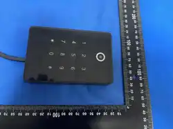
TWR-QM
A. Package Content
■ Reader, Installation manual
Accessory kit: Anchor Screw x 2, Anchor x 2, Screwdriver x 1, Screw x 2
■ Specification
˙:Dimension 120 x 80 x 20 mm
˙:~Voltage range DC 9 24V
˙:Current Max 200mA (DC 12V)
˙:Wiegand range up to 100M
RS485 range up to 1KM˙:
LED Triple color (Red/ Green/ Blue)˙:
B. Installation Guide
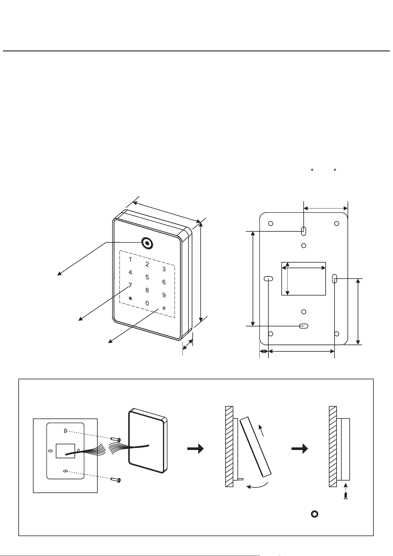
86mm
60mm
40mm
40mm
30mm
60mm
8mm
Install back case on the
wall and connect cable
Install reader : clip top side first then press down
Fasten torx screw
1
2
WallWall
WallWall
Wall
˙:Communication
˙WG 26/ 34/ 66
RS485 OSDP V1/ V2˙
˙Tamper Alarm
˙:-~Working temperature 20 C 70 C
˙Recommend shielded cable
Touch Keypad
80mm
120mm
20mm
QR Code Scanner
&
LED Status Ring
Sensing Area
1
7
2
DC 9~24V Input
5
6
3
4
8
C. Cable Instruction
D. Connection Example
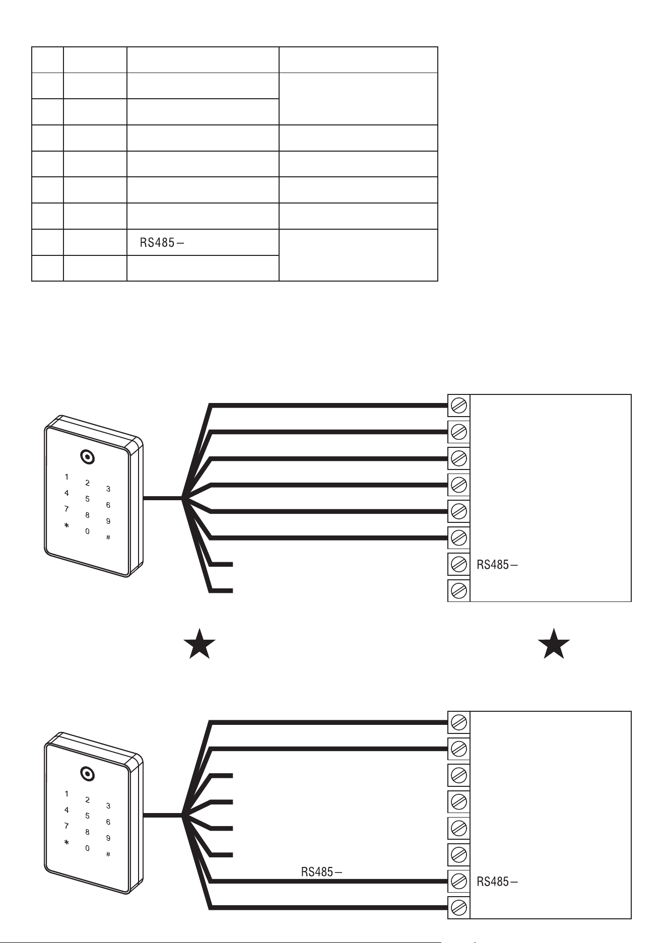
˙WG Communication
ORANGE
GREEN
WHITE
YELLOW
BLUE
BLACK
RED
Wiegand Data 1 Output
BROWN
No.
Color
DATA 1
DATA 0
VIN+(Power Positive)
GND (Power Negative)
Green LED Control
Red LED+Buzzer Control
RS485+
Function Description
Wiegand Data 0 Output
Grounding to work
Grounding to work
OSDP V1/ V2 Communication
Access Controller
˙OSDP Communication
VIN+
GND
WG IN D1
LED
Buzzer
WG IN D0
RS485+
Access Controller
VIN+
GND
WG IN D1
LED
Buzzer
WG IN D0
RS485+
BROWN
VIN+
GND
DATA 1
DATA 0
GREEN
WHITE
YELLOW
BLUE
BLACK
RED
Green LED Control
Red LED + Buzzer Control
ORANGE
RS485+
VIN+
GNDBLACK
RED
1
2
3
4
5
6
7
8
1
2
3
4
5
6
7
8
Disconnect power before wiring

FCC Warnning:
This equipment has been tested and found to comply with the limits for a Class B digital device,
pursuant to part 15 of the FCC Rules. These limits are designed to provide
reasonable
protection againstharmful interference in a residential installation. This equipment generates,
uses and can radiateradio
frequency
energy
and,
if
not
installed
and
used
in
accordance
with
the
instructions,
maycause
harmful
interference
to
radio
communications.
However,
there
is
no
guarantee
thatinterference
will
not
occur
in
a
particular
installation.
If
this
equipment
does
cause
harmfulinterference to radio or television reception, which can be
determined by turning the equipmentoff
and
on,
the
user
is
encouraged
to
try
to
correct
the
interference
by
one
or
more
of
thefollowing measures:
•
Reorient or relocate the receiving antenna.
•
Increase the separation between the equipment and receiver.
•
Connect the equipment into an outlet on a circuit different from that to which the receiver is
connected.
• Consult the dealer or an experienced radio/TV technician for help.
Caution:
Any
changes
or
modifications
to
this
device
not
explicitly
approved
by
manufacturer
could void your authority to operate this equipment.
This
device
complies
with
part
15
of
the
FCC
Rules.
Operation
is
subject
to
the
following
two
conditions:
(1)This
device
may
not
cause
harmful
interference,
and
(2)
this
device
must
accept
any
interference received, including interference that may cause undesired operation.
This
equipment
complies
with
FCC
radiation
exposure
limits
set
forth
for
an
uncontrolled
environment.
This
equipment
should
be
installed
and
operated
with
minimum
distance
20cm
between the radiator and your body.