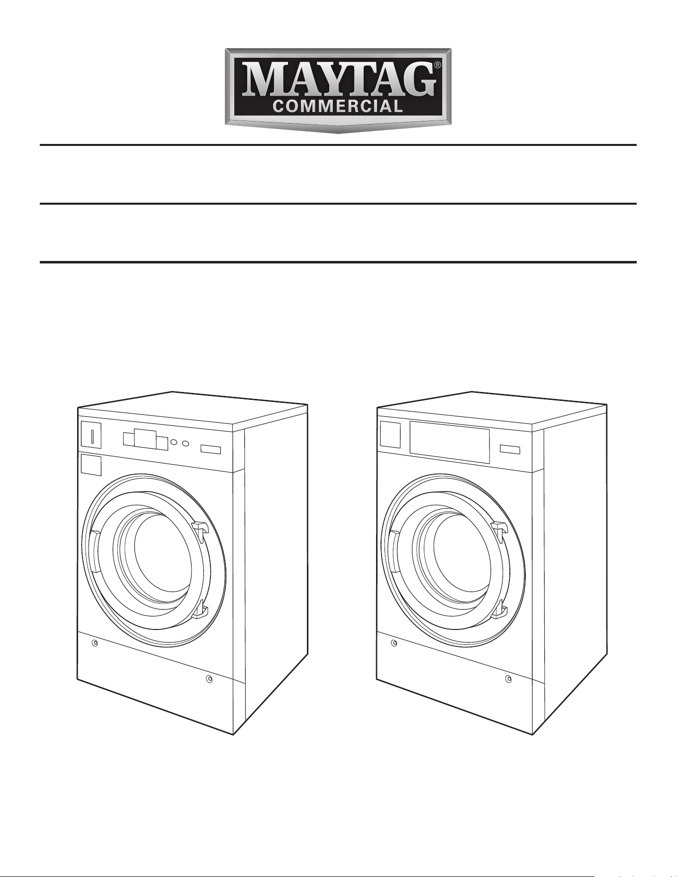
INSTALLATION INSTRUCTIONS
COMMERCIAL WASHER-EXTRACTOR
MYR20, MYR25, MYR30, MYR40, MYR55, MYR65
MYS20, MYS30, MYS40, MYS55, MYS65
www.maytagcommerciallaundry.com
WFR124390J
2
TABLE OF CONTENTS
WASHER SAFETY .......................................................................2
DIMENSIONS AND TECHNICAL SPECIFICATIONS ...............4
INSTALLATION REQUIREMENTS .............................................. 8
LOCATION REQUIREMENTS ..................................................... 8
ELECTRICAL REQUIREMENTS ................................................. 9
OPTIONS...................................................................................... 9
FLOOR REQUIREMENTS .........................................................10
INSTALLATION OF THE WASHER-EXTRACTOR
WITHOUT PEDESTAL BASE ....................................................11
INSTALLATION OF THE RIGID WASHER-EXTRACTOR
WITHOUT PEDESTAL BASE ....................................................12
INSTALLATION INSTRUCTION ................................................13
ELECTRICAL CONNECTION ...................................................14
WASHER MAINTENANCE ........................................................16
WARRANTY ...............................................................................17
WASHER SAFETY
You can be killed or seriously injured if you don't immediately
You
can be killed or seriously injured if you don't
follow
All safety messages will tell you what the potential hazard is, tell you how to reduce the chance of injury, and tell you what can
happen if the instructions are not followed.
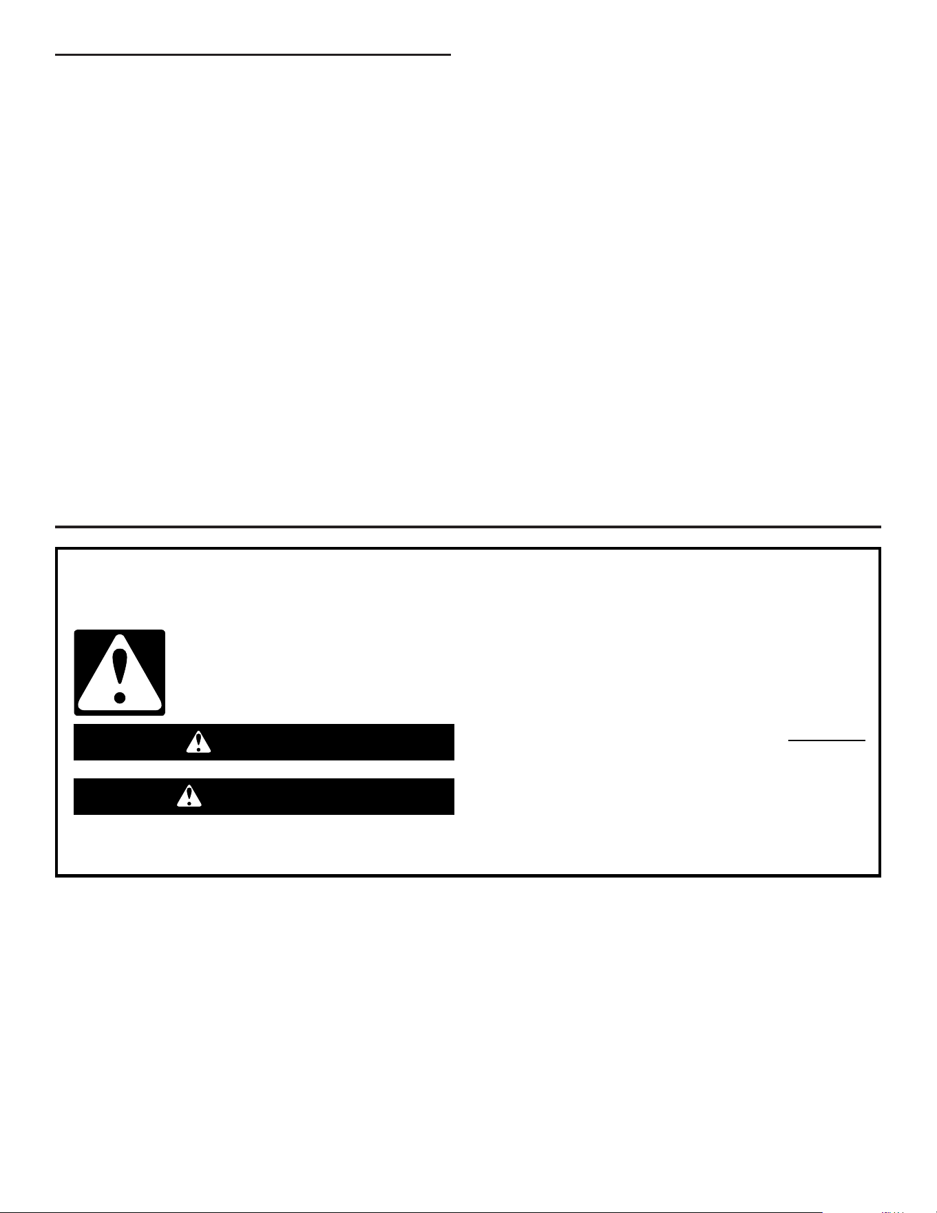
Your safety and the safety of others are very important.
We have provided many important safety messages in this manual and on your appliance. Always read and obey all safety
messages.
This is the safety alert symbol.
This symbol alerts you to potential hazards that can kill or hurt you and others.
All safety messages will follow the safety alert symbol and either the word “DANGER” or “WARNING.”
These words mean:
follow instructions.
instructions.
DANGER
WARNING

3
IMPORTANT:
■
The Circuit must be a dedicated circuit and may not be
combined with any lighting circuit.
■
Adequate grounding is essential to washer operation.
■
Do not fuse the neutral or grounding circuit.
■
Certain internal parts are intentionally not grounded and may
present a risk of electrical shock only during service. Do
not contact the inlet valve coil straps while the appliance is
energized.
■
This appliance must be connected to a grounded metal,
permanent wiring system, or an equipment-grounding
conductor must be run with the circuit conductors and
connected to the equipment-grounding terminal or lead on
the appliance.
■
Read all instructions before using the washer.
■
Do not wash articles that have been previously cleaned
in, washed in, soaked in, or spotted with gasoline,
dry-cleaning solvents, or other ammable or explosive
substances as they give off vapors that could ignite or
explode.
■
Do not add gasoline, dry cleaning solvents, or other
ammable or explosive substances to the wash water.
These substances give off vapors that could ignite or
explode.
■
Under certain conditions, hydrogen gas may be produced
in a hot water system that has not been used for 2 weeks
or more. HYDROGEN GAS IS EXPLOSIVE. If the hot water
system has not been used for such a period, before using
the washer, turn on all hot water faucets and let the water
ow from each for several minutes. This will release any
accumulated hydrogen gas. As the gas is ammable, do
not smoke or use an open ame during this time.
■
Do not allow children to play on, in, or with the washer.
Close supervision of children is necessary when the
washer is used near children.
■
Before the washer is removed from service or discarded,
remove the door or lid.
■
Do not reach into the washer if the drum, tub, or agitator is
moving.
■
Do not install or store the washer where it will be exposed
to the weather.
■
Do not tamper with controls.
■
Do not repair or replace any part of the washer or attempt
any maintenance unless specically recommended in this
manual that you understand and have the skills to carry
out.
■
See “Electrical Requirements” for grounding instructions.
■
This appliance must have power locked out using proper
lockout and tag out procedure during service and when
replacing parts. Refer to the OSHA standard for “The
Control of Hazardous Energy (Lockout/Tag out)”, Title 29
Code of Federal Regulations (CFR) Part 1910.147.
IMPORTANT SAFETY INSTRUCTIONS
WARNING: To reduce the risk of fire, electrical shock, or injury to persons when using the washer, follow basic precautions,
including the following:
SAVE THESE INSTRUCTIONS
Some models and features depicted in this booklet may not be available in your region or country.
4
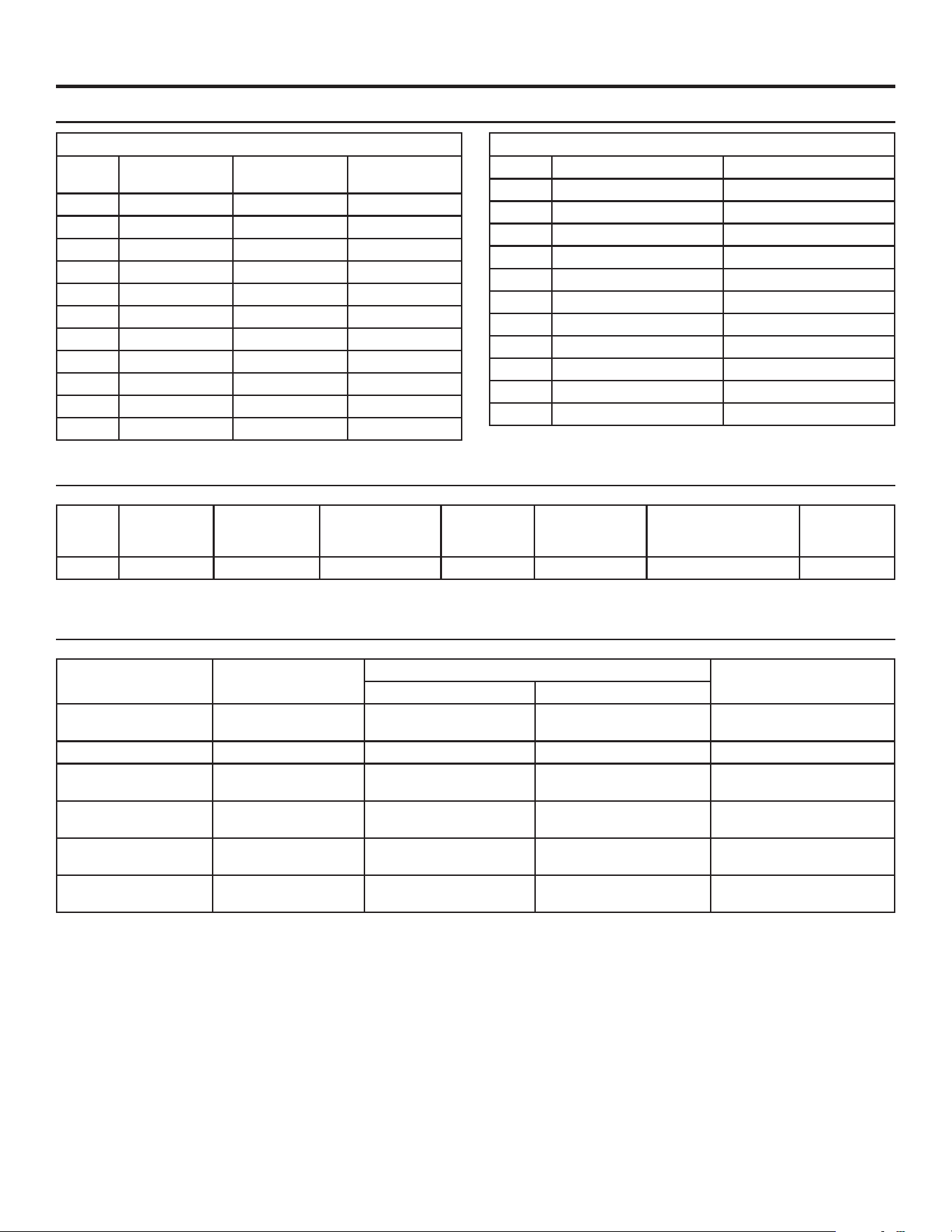
DIMENSIONS AND TECHNICAL SPECIFICATIONS
Model
Cylinder Volume
Liters (cubic feet)
Cylinder diameter
mm (in)
Cylinder depth
mm (in)
Dry load
capacity kg (lb)
Maximum
spin RPM
Maximum extract
force (G-force)
MYR20 73 (2.58) 530 (20.9) 352 (13.9) 9 (20) 838 200
MYR25 101 (3.55) 620 (24.4) 352 (13.9) 11 (25) 760 200
MYR30 131 (4.61) 620 (24.4) 454 (17.9) 14 (30) 760 200
MYR40 171 (6.04) 750 (29.5) 411 (16.2) 18 (40) 693 200
MYR55 230 (8.14) 750 (29.5) 548 (21.6) 25 (55) 693 200
MYR65 262 (9.25) 750 (29.5) 621 (24.4) 30 (65) 693 200
MYS20 73 (2.58) 530 (20.9) 352 (13.9) 9 (20) 1,165 400
MYS30 131 (4.61) 620 (24.4) 454 (17.9) 14 (30) 1,085 400
MYS40 171 (6.04) 750 (29.5) 411 (16.2) 18 (40) 985 400
MYS55 230 (8.14) 750 (29.5) 548 (21.6) 25 (55) 985 400
MYS65 262 (9.25) 750 (29.5) 621 (24.4) 30 (65) 912 350
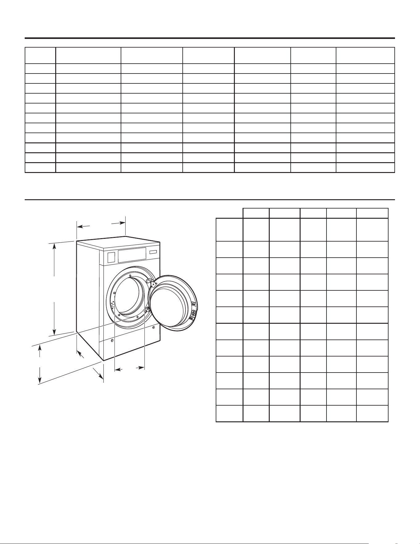
Dimensions
Washer Dimensions
C
D
A
E
B
A B C D E
Model
Width
mm
(in)
Door
Opening
mm (in)
Depth
mm
(in)
Height
mm (in)
Door
Height
mm (in)
MYR20
660
(26)
328
(12.9)
686
(27)
1,112
(43.8)
425
(16.8)
MYR25
750
(29.5)
410
(16.1)
725
(28.5)
1,222
(48.1)
419
(16.5)
MYR30
750
(29.5)
410
(16.1)
840
(33.1)
1,222
(48.1)
419
(16.5)
MYR40
890
(35.0)
459
(18.1)
876
(34.5)
1,410
(55.5)
537
(21.2)
MYR55
890
(35.0)
459
(18.1)
1,011
(39.8)
1,410
(55.5)
537
(21.2)
MYR65
890
(35.0)
459
(18.1)
1,085
(42.7)
1,410
(55.5)
537
(21.2)
MYS20
710
(28.4)
328
(12.9)
721
(28.4)
1,112
(43.8)
423
(16.7)
MYS30
795
(31.3)
410
(16.1)
872
(34.3)
1,222
(48.1)
420
(16.5)
MYS40
970
(38.2)
459
(18.1)
901
(35.5)
1,410
(55.5)
546
(21.5)
MYS55
970
(38.2)
459
(18.1)
1,037
(40.8)
1,410
(55.5)
546
(21.5)
MYS65
970
(38.2)
459
(18.1)
1,110
(43.7)
1,410
(55.5)
546
(21.5)
Additional Clearances:
■ Additional spacing of 1" (25 mm) on both sides of the washer
is required.
■ Additional spacing of 20" (500 mm) between the rear of the
washer and the wall is required.
■ Additional spacing of 34" (865 mm) above the washer is
required.
5
DIMENSIONS AND TECHNICAL SPECIFICATIONS
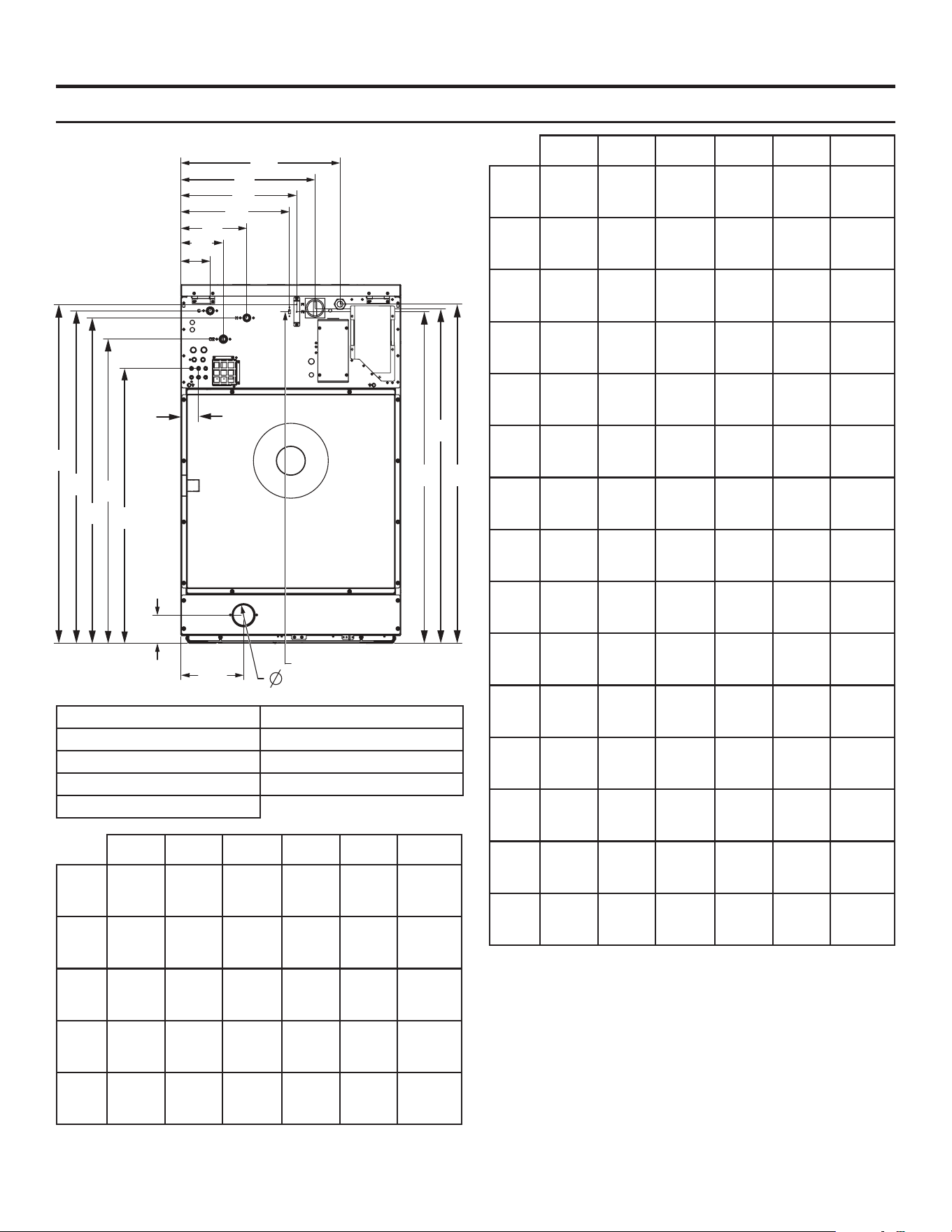
Dimensions
Washer Rear Dimensions
A. Electrical Connection F. Liquid Soap Connection
B. Hot Water G. Disconnect
C. Cold Water H. USB Port
D. 2
nd
Cold Water (Option) I. Fuses
E. Drain
MYR20 MYR25 MYR30 MYR40 MYR55 MYR65
A1
mm
(in)
451
(17.7)
543
(21.4)
543
(21.4)
578
(22.7)
578
(22.7)
578
(22.7)
A2
mm
(in)
1,045
(41.1)
1,156
(45.5)
1,156
(45.5)
1,343
(52.8)
1,343
(52.8)
1,343
(52.8)
B1
mm
(in)
225
(8.8)
225
(8.8)
225
(8.8)
289
(11.4)
289
(11.4)
289
(11.4)
B2
mm
(in)
1,000
(39.4)
1,108
(43.6)
1,108
(43.6)
1,224
(48.2)
1,224
(48.2)
1,224
(48.2)
C1
mm
(in)
101
(4.0)
101
(4.0)
101
(4.0)
175
(6.8)
175
(6.8)
175
(6.8)
MYR20 MYR25 MYR30 MYR40 MYR55 MYR65
C2
mm
(in)
1,023
(40.3)
1,133
(44.6)
1,133
(44.6)
1,321
(52)
1,321
(52)
1,321
(52)
D1
mm
(in)
146
(5.7)
146
(5.7)
146
(5.7)
175
(6.8)
175
(6.8)
175
(6.8)
D2
mm
(in)
927
(36.5)
1,035
(40.8)
1,035
(40.8)
1,224
(48.2)
1,224
(48.2)
1,224
(48.2)
E1
mm
(in)
168
(6.6)
213
(8.4)
213
(8.4)
283
(11.1)
283
(11.1)
283
(11.1)
E2
mm
(in)
95
(3.7)
95
(3.7)
95
(3.7)
133
(5.2)
133
(5.2)
133
(5.2)
E3
mm
(in)
70
(2.8)
70
(2.8)
70
(2.8)
70
(2.8)
70
(2.8)
70
(2.8)
F1
mm
(in)
60
(2.3)
70
(2.7)
70
(2.7)
70
(2.7)
70
(2.7)
70
(2.7)
F2
mm
(in)
826
(32.5)
937
(36.9)
937
(36.9)
1,095
(43.1)
1,095
(43.1)
1,095
(43.1)
G1
mm
(in)
368
(14.5)
458
(18)
458
(18)
492
(19.4)
492
(19.4)
492
(19.4)
G2
mm
(in)
1,032
(42.6)
1,140
(44.9)
1,140
(44.9)
1,330
(52.3)
1,330
(52.3)
1,330
(52.3)
H1
mm
(in)
280
(11)
371
(14.6)
371
(14.6)
406
(16.0)
406
(16.0)
406
(16.0)
H2
mm
(in)
1,019
(40.1)
1,130
(44.5)
1,130
(44.5)
1,317
(51.8)
1,317
(51.8)
1,317
(51.8)
I1
mm
(in)
305
(12)
394
(15.5)
394
(15.5)
429
(16.8)
429
(16.8)
429
(16.8)
I2
mm
(in)
1,054
(41.5)
1,155
(45.5)
1,155
(45.5)
1,343
(52.9)
1,343
(52.9)
1,343
(52.9)
I3
mm
(in)
1,019
(40.1)
1,130
(44.5)
1,130
(44.5)
1,318
(51.8)
1,318
(51.8)
1,318
(51.8)
I2
C1
D1
B1
A1
I1
H1
G1
F1
C2
B2
D2
I3
G2
A2
F2
E2
E1
E3
H2
6
DIMENSIONS AND TECHNICAL SPECIFICATIONS
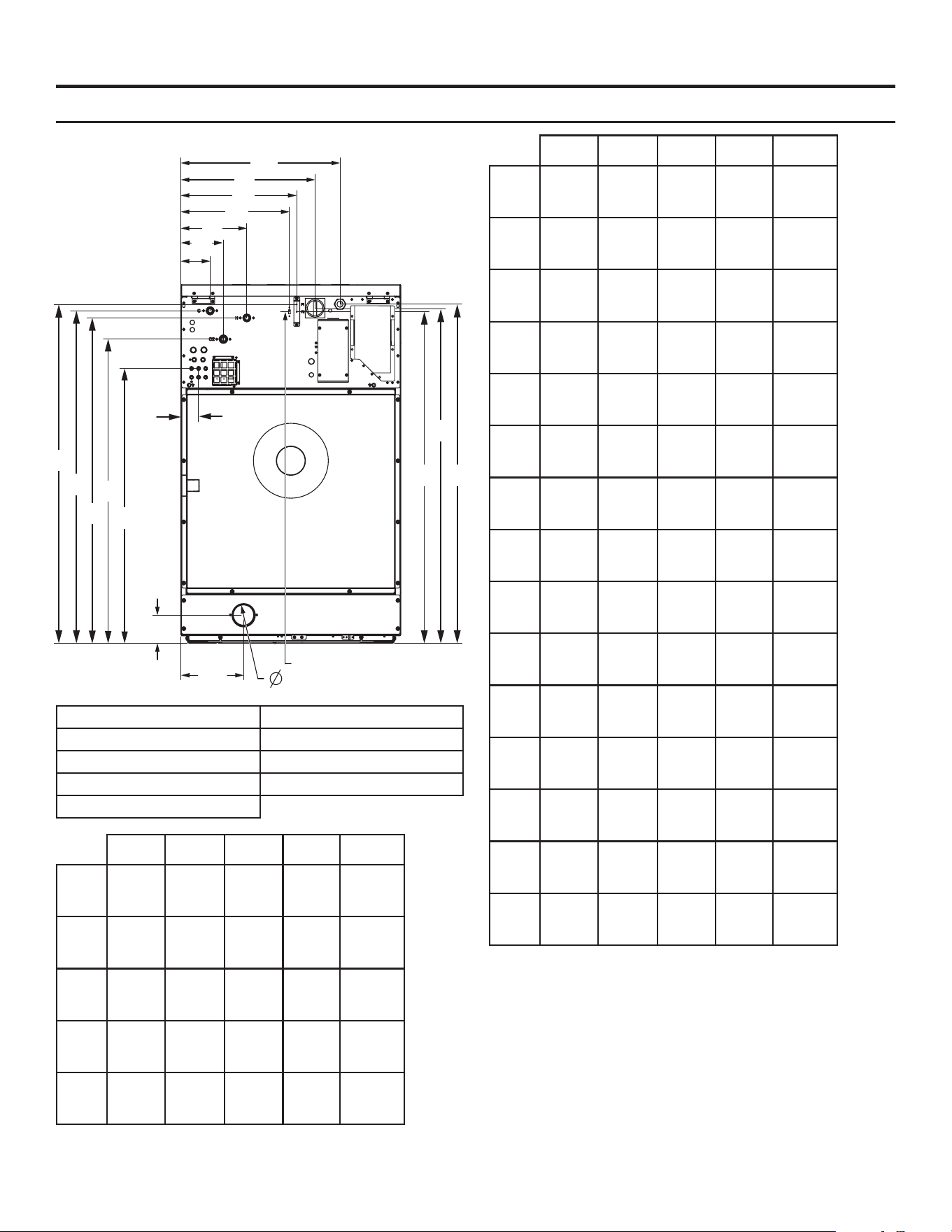
Dimensions
Washer Rear Dimensions
A. Electrical Connection F. Liquid Soap Connection
B. Hot Water G. Disconnect
C. Cold Water H. USB Port
D. 2
nd
Cold Water (Option) I. Fuses
E. Drain
MYS20 MYS30 MYS40 MYS55 MYS65
A1
mm
(in)
502
(19.8)
588
(23.2)
657
(25.8)
657
(25.8)
657
(25.8)
A2
mm
(in)
1,048
(41.3)
1,159
(45.7)
1,347
(53)
1,347
(53)
1,347
(53)
B1
mm
(in)
225
(8.8)
225
(8.8)
300
(11.8)
300
(11.8)
300
(11.8)
B2
mm
(in)
1,003
(39.4)
1,112
(43.8)
1,228
(48.4)
1,228
(48.4)
1,228
(48.4)
C1
mm
(in)
101
(4.0)
101
(4.0)
175
(6.9)
175
(6.9)
175
(6.9)
MYS20 MYS30 MYS40 MYS55 MYS65
C2
mm
(in)
1,028
(40.5)
1,137
(44.8)
1,324
(52.2)
1,324
(52.2)
1,324
(52.2)
D1
mm
(in)
146
(5.8)
146
(5.8)
175
(6.9)
175
(6.9)
175
(6.9)
D2
mm
(in)
930
(36.7)
1,041
(41)
1,228
(48.8)
1,228
(48.8)
1,228
(48.8)
E1
mm
(in)
229
(9)
229
(9)
270
(10.7)
270
(10.7)
270
(10.7)
E2
mm
(in)
90
(3.5)
90
(3.5)
111
(4.4)
111
(4.4)
111
(4.4)
E3
mm
(in)
70
(2.8)
70
(2.8)
70
(2.8)
70
(2.8)
70
(2.8)
F1
mm
(in)
70
(2.8)
70
(2.8)
70
(2.8)
70
(2.8)
70
(2.8)
F2
mm
(in)
826
(32.5)
936
(36.9)
1,094
(43.1)
1,094
(43.1)
1,094
(43.1)
G1
mm
(in)
419
(16.5)
502
(19.8)
572
(22.5)
572
(22.5)
572
(22.5)
G2
mm
(in)
1,035
(40.8)
1,146
(45.2)
1,334
(52.5)
1,334
(52.5)
1,334
(52.5)
H1
mm
(in)
330
(13)
416
(16.4)
486
(19.2)
486
(19.2)
486
(19.2)
H2
mm
(in)
1,023
(40.3)
1,133
(44.6)
1,321
(52)
1,321
(52)
1,321
(52)
I1
mm
(in)
355
(14)
441
(17.4)
511
(20.2)
511
(20.2)
511
(20.2)
I2
mm
(in)
1,048
(41.3)
1,159
(45.7)
1,347
(53)
1,347
(53)
1,347
(53)
I3
mm
(in)
1,023
(40.3)
1,133
(44.6)
1,321
(52)
1,321
(52)
1,321
(52)
I2
C1
D1
B1
A1
I1
H1
G1
F1
C2
B2
D2
I3
G2
A2
F2
E2
E1
E3
H2
7
DIMENSIONS AND TECHNICAL SPECIFICATIONS
Dimensions
Crated Dimensions
Model
Crated Width
mm (in)
Crated Depth
mm (in)
Crated Height
mm (in)
MYR20 705 (27.8) 841 (33.1) 1,270 (50.0)
MYR25 800 (31.5) 880 (34.6) 1,381 (54.4)
MYR30 800 (31.5) 991 (39.0) 1,381 (54.4)
MYR40 940 (37.0) 1,029 (40.5) 1,560 (61.43)
MYR55 940 (37.0) 1,169 (46.0) 1,560 (61.4)
MYR65 940 (37.0) 1,242 (48.9) 1,560 (61.4)
MYS20 756 (29.8) 854 (33.4) 1,270 (50.0)
MYS30 841 (33.1) 1,010 (39.8) 1,381 (54.4)
MYS40 1,003 (39.5) 1,042 (41.0) 1,560 (61.4)
MYS55 1,003 (39.5) 1,178 (46.4) 1,560 (61.4)
MYS65 1,003 (39.5) 1,251 (49.3) 1,560 (61.4)
Approximate Weight
Model Uncrated-kg (lb) Crated-kg (lb)
MYR20 151 (333) 166 (365)
MYR25 203 (447) 218 (480)
MYR30 222 (489) 237 (523)
MYR40 312 (688) 328 (724)
MYR55 332 (732) 349 (769)
MYR65 347 (764) 364 (802)
MYS20 188 (415) 202 (446)
MYS30 264 (582) 279 (616)
MYS40 386 (851) 403 (889)
MYS55 406 (894) 423 (933)
MYS65 428 (944) 446 (984)
Water, Drain, External Supply Connections
Model
Number of
water inlets
Optional third
water inlet
Inlet sizes
(BSPP*)
Operating
Pressure
Bar (Psi)
Number of
dispenser
compartments
External chemical
connections, number
Drain valve
drain, Size
mm (in)
ALL 2 Yes 3/4" 1-8 (20-120) 4 10 76 (3)
* = 3/4" GHT adapter included for machines sold in North America.
Energy/Water Usage
Model
Capacity
(lbs)
Average Cycle Water Use (Gallons)
Total/Hot Ratio
Hot Water Total Water
MYR20
MYS20
20 4 11.7 2.925
MYR25 25 6 17.6 2.925
MYR30
MYS30
30 8 23.4 2.925
MYR40
MYS40
40 11 32.2 2.925
MYR55
MYS55
55 14 41 2.925
MYR65
MYS65
65 17 49.7 2.925
8
INSTALLATION REQUIREMENTS
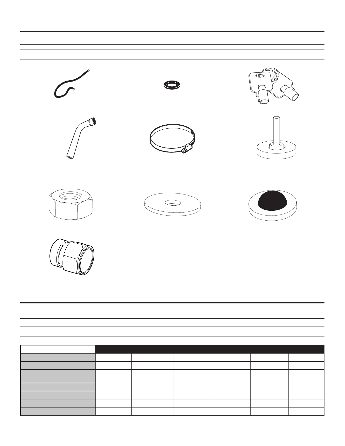
Tools and Parts
Parts supplied:
Water inlet hoses (2) Inlet hose washers (4) Service Keys
Drain hose Hose clamp
Foot Leveling (4)
(MYS20, MYS30, MYS40, MYS55,
MYS65 only)
LOCATION REQUIREMENTS
Forces transmitted by the washing machine
MYR20 MYR25 MYR30 MYR40 MYR55 MYR65
Static oor load (kN - lb) 1.49 (334) 1.99 (447) 2.18 (489) 3.07 (688) 3.26 (731) 3.40 (764)
Dynamic oor load (kN - lb) 2.42 (543) 4.01 (900) 5.12 (1,150) 5.60 (1,260) 7.52 (1,690) 8.82 (1,981)
Maximum vertical load
(kN - lb)
3.91 (877) 6.00 (1,347) 7.30 (1,639) 8.67 (1,948) 10.80 (2,421) 12.22 (2,745)
Dynamic load fr
equency (Hz) 13.97 13.20 13.17 11.59 11.55 11.59
G factor 200 200 200 200 200 200
Anchorage points 4 4 4 8 8 8
Min Concrete Thk. (mm - in) 100 (4) 100 (4) 150 (6) 150 (6) 200 (8) 200 (8)
Nut (4)
(MYS20, MYS30, MYS40, MYS55, MYS65 Only)
Filter screen (2)
(MYR55, MYS55, MYR65, MYS65 only)
Washer
(4) (MYR20, MYR25, MYR30 only)
(8) (MYR40, MYR55, MYR65 only)
Metric thread adapter (2)
(Countries with metric pipe connections)
9
Model
Capacity
(lb)
RPM
Voltage
(1P)
Frequency
(Hz)
Total
Amps
Circuit
Breaker
Conductor
Size
MYR20 20 838
115 60 9.6 15 14
208-240 50/60 4.8 15 14
MYR25 25 790
115 60 14.3 20 12
208-240 50/60 8.1 15 14
MYR30 30 790
115 60 16.2 20 12
208-240 50/60 8.1 15 14
MYR40 40 693 208-240 50/60 12.5 15 14
MYR55 55 693 208-240 50/60 12.5 15 14
MYR65 65 693 208-240 50/60 12.5 15 14
MYS20 20 1,165
115 60 14.3 20 12
208-240 50/60 8.1 15 14
MYS30 30 1,085 208-240 50/60 13.2 20 12
MYS40 40 985 208-240 50/60 16.2 20 12
MYS55 55 985 208-240 50/60 18.6 25 12
MYS65 65 915 208-240 50/60 18.6 25 12
This appliance is intended to be connected to a supply circuit protected by an over current-protective device (fuse breaker) sized
according to the “Circuit Breaker (D-Curve)” column appropriate to your location.
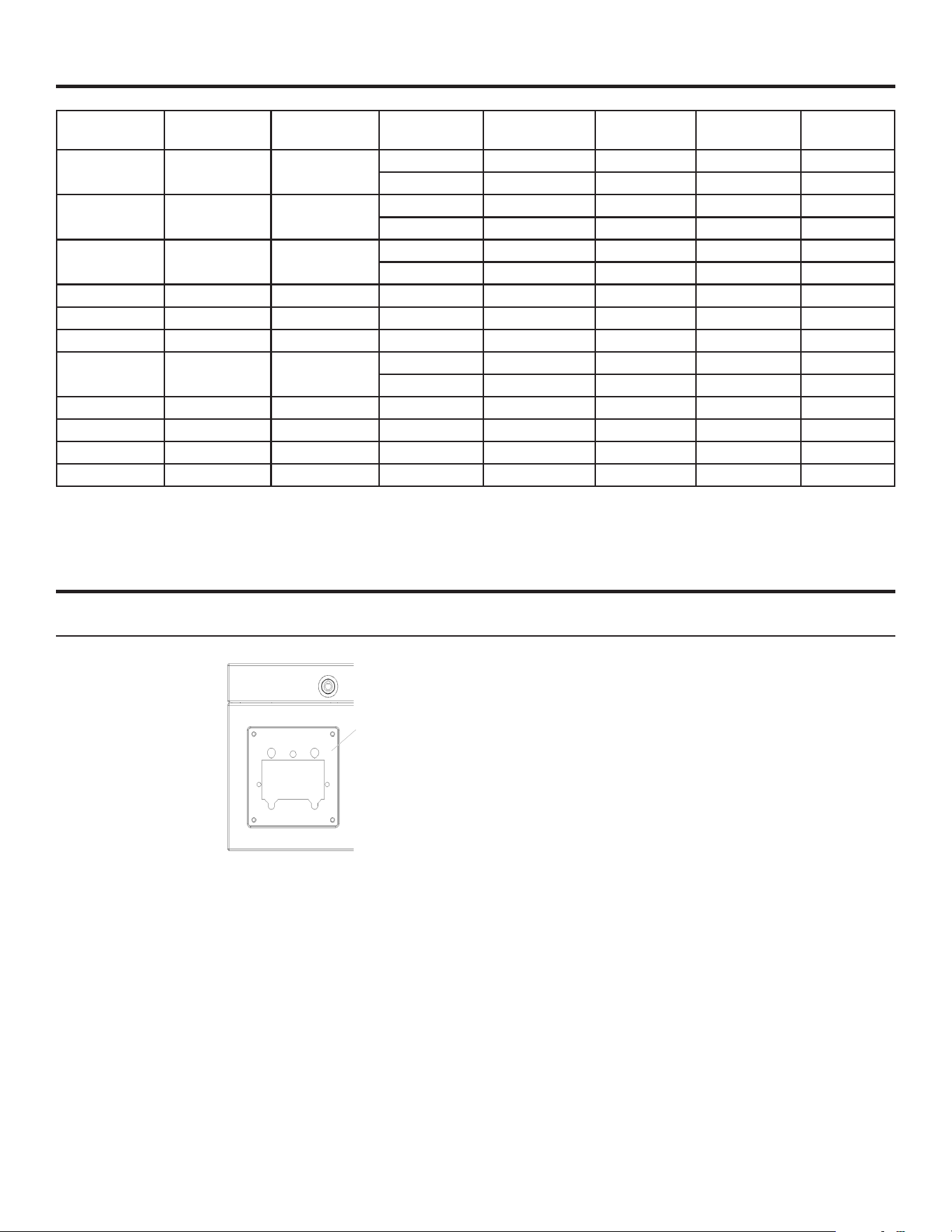
OPTIONS
PX (Coin Ready) and PR (Card Reader Ready) models only
A card reader adapter plate is provided with PX and PR models.
PX: This washer is coin acceptor ‘cable’ ready. It will accept a variety of coin acceptors, but does NOT come with a coin acceptor.
Refer to the coin acceptor manufacturer for proper washer set-up. Prior to installing a coin accepter, remove the card reader adapter
plate by removing (x4) M4 nuts.
PX models are also debit card ‘cable’ ready (refer to PR information, below for proper setup).
PR: This washer is debit card ‘cable’ ready. It will accept a variety of debit card systems, but does NOT come with a debit card reader.
Refer to the debit card reader manufacturer for proper washer set-up. In models converted to a generation 1 debit card system, debit
pulses represent the equivalent of one coin (coin 1).
Card reader
adapter plate
ELECTRICAL REQUIREMENTS
10
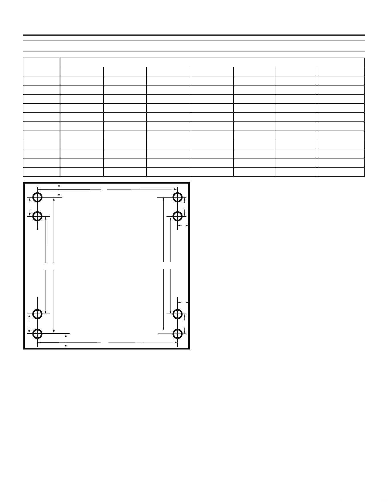
FLOOR REQUIREMENTS
Mounting Holes Placement
Model
Distance
A (mm/in) B (mm/in) C (mm/in) D (mm/in) E (mm/in) F (mm/in) G (mm/in)
MYR20
519/20.4 474/18.7 N/A N/A 70/2.7
65
/2.6
167
/6.6
MYR25
615/24.2 474/18.7 N/A N/A 67/2.6
65
/2.6
186
/7.3
MYR30
615/24.2 574/22.6 N/A N/A 67/2.6
65
/2.6
201
/7.9
MYR40
751/29.6 580/22.8 82/3.2 416/16.4 70/2.7
52
/2
253
/9.9
MYR55
751/29.6 716/28.2 82/3.2 552/21.7 70/2.7
52
/2
253
/9.9
MYR65
751/29.6 789/31.0 82/3.2 625/24.6 70/2.7
52
/2
253
/9.9
MYS20
379/14.9 592/23.3 N/A N/A 166/6.5
45
/1.8
84
/3.3
MYS30
499/19.7 708/27.9 N/A N/A 148/5.8
47
/1.8
177
/4.6
MYS40
669/26.3 661/26.0 N/A N/A 151.0/5.9
50
/2.0
190
/7.5
MYS55
669/26.3 797/31.4 N/A N/A 151.0/5.9
50
/2.0
190
/7.5
MYS65
669/26.3 870/34.3 N/A N/A 151.0/5.9
50
/2.0
190
/7.5
There are separate instructions if using a pedestal (those
instructions are in the pedestal installation manual).
There are separate instructions if using an optional front mount
adapter plate (those details are in the front mount adapter plate
installation manual).
A
A
B
B
C
C
C
C
D
D
E
E
Front
G
F
11
INSTALLATION OF THE WASHER-EXTRACTOR WITHOUT
PEDESTAL BASE
Anchoring MYR models (Rigid Machines)
A static engineer must be consulted to evaluate the static
requirements with respect to permissible loads, vibrations, and
noise level in the building where the washer is installed.
The manufacturer does not recommend installing the washer
in a room with a cellar underneath or on a oor with rooms
underneath. The washer must be leveled from side to side, as
well as from front to rear. If the washer is not properly leveled,
it may become out of balance even though the drum remains
balanced.
Rigid washers must be anchored to the oor. Correct
construction of the anchorage to the oor is essential to ensure
correct operation of the appliance and to prevent serious
damage to its structure.
Rigid washers must not be installed on non-foundation oors
without authorization from a technician familiar with the structure
and weight-bearing capacity of the building.
Check the weight of the washer and its contents, plus the
dynamic forces generated during spinning. The manufacturer
does not accept responsibility for any damage due to vibration in
this type of installation.
Anchoring MYS models (Soft Machines)
Shipping brackets need to be uninstalled from the soft washers
prior to operation. Remove the toe panel, front panel, and rear
cover to access the shipping bracket. The shipping brackets are
painted white for ease of identication.
Leveling feet are provided with soft machines. Use the feet to
level the machine in it's nal operating location. Use the level to
level the top of the washer. Turn the leveling legs to adjust the
setting. Check that the washer does not move front-to-back,
side-to-side, or diagonally when pushed on its top edges. Keep
the legs as short as possible for best performance.
Once the washer is leveled the lock nuts must be tightened up
against the top of the foot bushing with the 17 mm (11/16") open
end wrench. This will keep the setting from changing.
Anchoring is not required but four 12 mm holes are provided if
anchoring is desired.
There is a whisker switch behind the toe panel, located below
the tub and to the left of the drain. This switch is set at the
factory, but in the event that it falls out of adjustment, with the
shipping brackets installed, this switch should be set so the
whisker is centered in the opening.
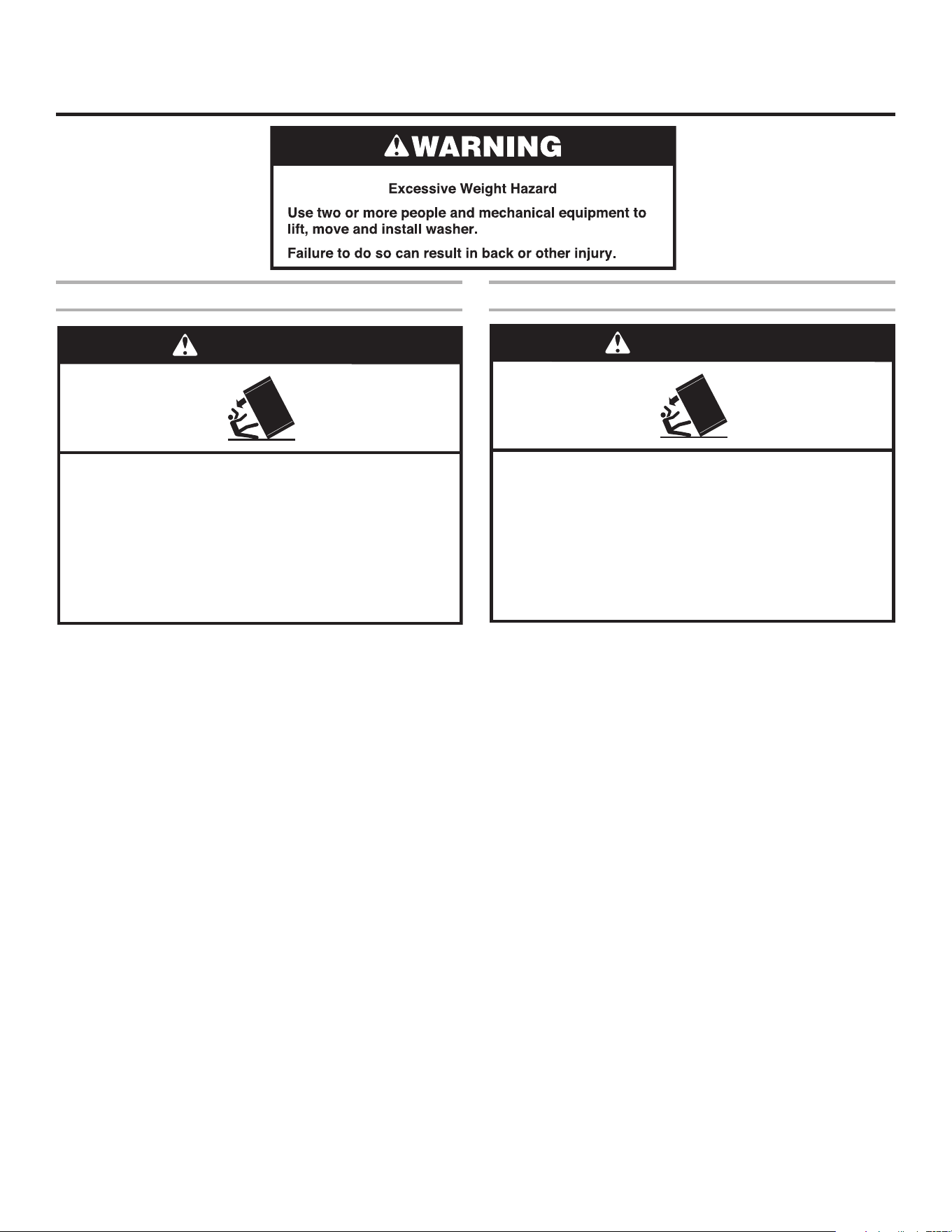
WARNING
Crush Hazard
Washer can tip over if not properly installed on
platform or pedestal.
Shipping brackets must be removed per installation
instructions before operating.
Failure to follow these instructions can result in death
or serious injury.
WARNING
Crush Hazard
Washer can tip over if not properly installed on
platform or pedestal.
Washer must be bolted to the floor per installation
instructions.
Failure to follow these instructions can result in death
or serious injury.

12
INSTALLATION OF THE RIGID WASHER-EXTRACTOR
WITHOUT PEDESTAL BASE
Using Expansion Bolts
Before anchoring the machine to the oor, make sure that its
minimum resistance is equal or higher than 3,500 psi (25 N/mm
2
).
First mark the locations of the mounting holes using the
dimensions specied in the “Rigid Washing Machines” chart.
Next drill the mounting holes. Follow the manufacturing
installation instructions, but the holes must be at least 4"
(100 mm) deep. The holes must not go all the way through the
oor. Clean the holes with compressed air.
For the smoothest operation Whirlpool recommends that the
washer be set with a precision, high strength, non-metallic,
non-shrink grout designed for precision grouting. Grout should
have a minimum compressive strength of 10,000 psi (69 MPa),
when mixed to a plastic consistency and fully cured.
a. If the washer is to be grouted in, it should be level and
spaced between 3/8" (9 mm) and 1/2" (13 mm) off the oor
to make room for the grout.
b. Remove the washer leaving the spacers behind.
c. Mix the grout to a plastic consistency per the manufacturer's
instructions.
d. Trowel the grout in to a depth slightly greater than the height
of the spacers.
e. Reinstall the washer over the mounting fasteners. Use the
fasteners to pull the washer down securely on the spacers.
Do not fully torque the fasteners.
f. Clean away any excess grout outside the washer as per the
manufacturer's instructions.
g. Allow the grout to set for the minimum time recommended
by the grout manufacturer for light use.
h. Tighten the bolts until the machine is securely fastened.
If not using grout, place the washer-extractor in position over the
holes, then insert the expansion bolts in the holes. Be sure to
use 5/8-11 (M16) expansion bolts, and that they protrude above
the surface by 2" (50 mm). Once in place, tighten the bolts. Place
the washer-extractor in position above the bolts, and gradually
tighten the nuts one after another to 195 Nm (144 ft lb).
Using J-bolts
Before anchoring the machine to the oor, make sure that its
minimum resistance is equal or higher than 3,500 psi (25 N/mm
2
).
First mark the locations of the mounting holes using the
dimensions specied in the “Rigid Washing Machines” chart.
Next make holes to a depth, at minimum, equal to 4" (100 mm).
Make the holes big enough to insert the J-bolt and clean using
compressed air. Insert the J-bolts in the holes and secure using
a suitable anchoring compound, ensuring that the bolt protrudes
above the surface by 2" (50 mm). Be sure to use 5/8-11 (M16)
J-bolts.
Place the washer-extractor in position above the bolts, and
gradually tighten the nuts one after another 195 Nm (144 ft lb).
Check the condition of the J-bolts one week after installation.
4"
minimum
(100 mm)
minimum
4"
(100 mm)
13
INSTALLATION INSTRUCTION
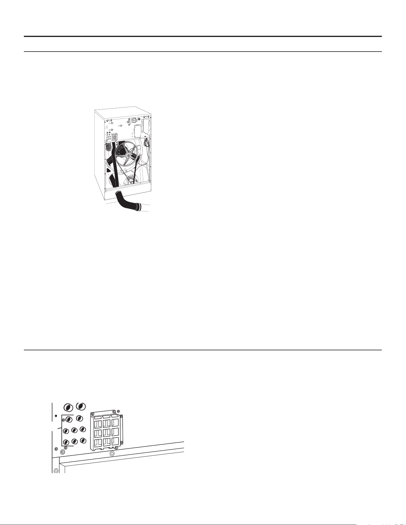
Connect the Drain Hose
1. The drain hose can be found shipped inside the drum
with the installation kit. The clamp for this hose is in the
installation kit. Attach the drain to the drain connection
located near the bottom of the rear of the washer. This is a
gravity-fed system, so you must install the drain hose with
the outlet lower than the drain connection to ensure proper
drainage. Do not kink the hose.
Drain Hose
2. The drain hose should end over, or in a floor drain or
drainage canal.
3. The drainage canal or drain pipe must be sized properly
to handle the total output of all washers connected to the
system. Each time a washer is added to the drain pipe,
the size of the pipe must increase to accommodate the
additional volume. The drain pipe at the first washer must
be 3" (76 mm) diameter. The pipe must increase to
4" (100 mm) diameter before the second washer and
5" (127 mm) diameter before the third washer.
Drain Connections
Use the provided drain hose to connect the washer’s drain pipe
to the facility drain or drain channel. Secure with the provided
clamp. The capacity of discharged water for each washer model
is 55.5 gallon/min (210 L/min).
Water Hardness
Determine the water hardness level in water supply. Good wash
results are dependent on water hardness. In areas that have
medium and very hard water levels, a water softener may be
required.
Contact your water or soap distributor for determining the proper
soap and detergents to be used with your hardness levels for the
best wash results.
Water Supply Connections
Washers have 2 water inlets. For connection dimensions, see
“Dimensions and Technical Specications”.
1. Always use the exible hoses delivered with the washer. Do
not use a xed connection to the water supply.
2. Keep proper water pressure within range. See “Dimensions
and Technical Specifications”.
3. The water connection to the washer requires a 3/4" British
Standard Pipe Thread fitting. The British Standard Pipe
Thread end is identified with a label. Threading an GHT fitting
or the GHT end of the adapter hose will damage the threads
of the washer.
4. Flush water lines to remove debris. For countries with metric
water supply connection, see “NOTE” below. Install the GHT
(the end with no label) side of the inlet hoses to the hot and
cold supply lines. Tighten fittings.
NOTE: Metric thread adapters are provided in countries
that require them. These brass adapters have internal BSPP
threads and external NPT threads. One adapter should be
attached (with sealing washer) to the GHT end of each water
inlet hose. With this assembly, metric threads are now on
both ends of the water inlet hose.
5. Attach the BSPP (the end with the label) end of adapter
hoses to the washer. (On 55R, 55S, 65R, and 65S models,
there is a hose screen included in the installation kit that
needs to be placed here). Tighten fittings.
6. Turn on water and check for leaks in the system.
External Supply Connections
All external liquid soap hose connections must be tight. Double
check that the clamps are tight after connections are made.
Make sure any unused open connections are sealed with an
appropriate cover.
The connections for the liquid soap are on the rear of the
washer and must be drilled open in order to use them. Only drill
out the connections that will be used. There are 8
3/8" (9 mm) diameter connections; use a 5/16" (8 mm) diameter
drill bit to drill out these holes. There can only be 8 pumps in the
system. Be sure to clean out all the drill shavings completely so
they do not clog the inlets and hoses. Connect to liquid soap
pumps to the left openings rst. Set the ow rate of the pumps
between 16 and 26 gallon/hr (60 and 100 L/hr).
IMPORTANT: The incoming water dilutes the liquid soap and
brings it into the tub assembly.
Check with your liquid soap provider to ensure that your soap
is inert to Polypropylene (PP) and Polyvinyl Chloride (PVC)
materials.
Make sure the hoses and wiring for the liquid soap pumps are
not damaged, pinched, rubbed or damage to the machine could
occur.
The liquid soap pumps used must be capable of providing the
requested quantity in less than 30 seconds.
Liquid Soap
Connections
14
ELECTRICAL CONNECTION
Connection to Washer:
The washer must be electrically grounded in accordance with all
local codes or, in the absence of local codes, with the National
Electrical Code, ANSI/NFPA 70, latest edition, or Canadian
Electrical Code, CSA C22.1
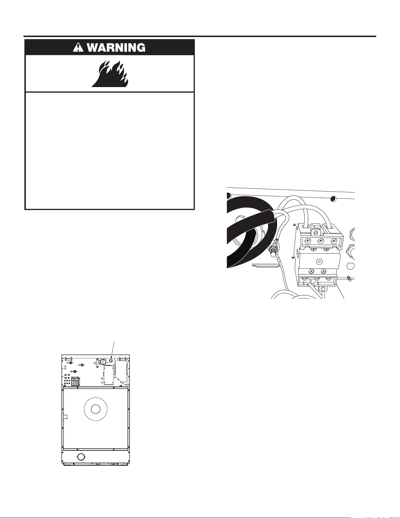
Direct Wire Installation:
Power supply cable must match power supply (3-wire) and be:
■
To access the disconnect, lift the top cover and support it
with the prop rod.
■
Copper wire of appropriate gauge for amperage requirement
(see “Manufacturer’s Recommended Minimal Conductor
section”). Solid wire is recommended. Do not use aluminum
wire.
■
Flexible armored cable or exible conduit must be used
for the supply connections. Use the hole in the rear of the
washer for routing. Connection is made directly to the
disconnect switch inside the back top panel of the washer.
The Aluminum Lug for Ground is next to that disconnect
body. A Flat-head screwdriver can be used for the power
wires to the disconnect as well as the ground to the
lug. Incoming service wires are applied to the top of the
disconnect body. If the washer is single phase, (only
2 power wires) the outside positions of the disconnect should
be used (leaving the center pole empty). Tighten down all
connections including the unused position in the single-
phase service case. Leaving a small radius of slack for the
wires inside the washer, check that the cable is well held in
place.
■
Check the rating plate on the washer. Make sure that the
supply phase and voltage match the rating of the washer.
Some locations require an autonomous power switch (I) at
the current input, with a minimum of 0.12" (3 mm) between
contacts. Fit a 300 mA, type A, immediate response
differential protection. Check your local regulations. Insert the
exible armored cable or exible conduit through the hole in
the rear panel. Secure the armored cable or conduit to the
rear panel. Connect the wiring per the correct illustration.
Knock out for
Electrical Connection
PE
L1
L2
Single Phase
Fire Hazard
Use appropriate gauge of solid copper wire. (See chart
in “Electrical Requirements” section).
Use a UL listed strain relief.
Disconnect power before making electrical connections.
Connect neutral wire (white) to terminal (N).
Ground wire (green or bare wire) must be connected
to ground connector (PE).
Connect remaining 3 supply wires to remaining
3 terminals (L1, L2 and L3).
Securely tighten all electrical connections.
Failure to do so can result in death, fire, or
electrical shock.
15
ELECTRICAL CONNECTION
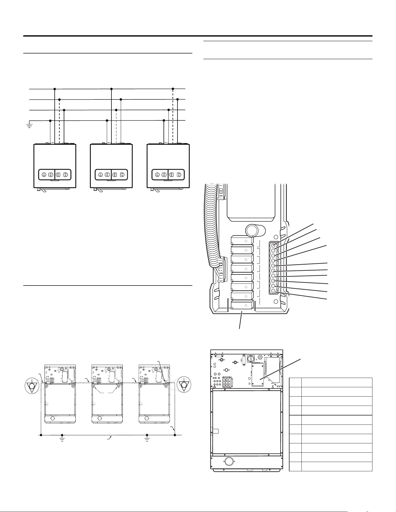
Multiple Single-Phase Machines in Line
When installing multiple single-phase washers into an existing
3-phase power supply, alternating the phases used as the hot
leg is recommended to evenly distribute power on the system.
See illustration.
Instructions For Grounding
This appliance must be connected to an equipment grounding
conductor that must run with the circuit conductors and
connected to the aluminum ground lug inside the rear electric
panel.
Connect the terminal strip and check that the connections
correspond to the operating voltage. Fit a 300 mA, type A,
immediate response differential protection.
The machine must be grounded. See the illustration on the
previous page.
Equipotential Bonding
In addition to the equipment-grounding conductor discussed
earlier that runs with the circuit conductor's and is connected
to the equipment grounding terminal, all washers or appliances
in the vicinity must be permanently interconnected with a
equipotential bonding conductor.
The external connection points marked on the back of the
washer serve for this purpose. See illustration below.
The cross-sectional area of the conductor must be at least
electrically equivalent to the cross-sectional area of the copper
conductor used to power the washer.
1. Protective grounding structure
2. External protective conductor connection point
3. Protective conductor
4. Grounding identication
Electrical connection of the liquid soap supply
system, if supplied (Optional on vended machines)
The power supplied to the liquid soap system must come from
an external electric source. Do not connect the system in the
washer. All work must be performed by a qualied technician in
compliance with all applicable local codes. Refer to the wiring
diagram found inside the washer attached to the side panel.
There is a labeled terminal block on the rear of the washer for
control signal connections. There is a corresponding strip of LED
lights to show when each signal is active. Refer to the wiring
diagram found inside the washer attached to the side panel.
Supply pump control signals are 24 VAC, maximum current is
10 mA. Wiring from the liquid soap system must be UL
Recognized (AVLV2 and AVLV8) and rated for 300 V minimum.
Route all wires through the supplied plastic bushing, making
sure to secure them with the cable clamp. Afx the cover to
the terminal block access before applying electric power to the
washer. See the Programming Guide for details on programming
the liquid soap system.
C2
C
H
F1
F2
LED
Lights
External Liquid Soap
Connection Cover
1
2
10
9
8
5
7
3
4
6
PE L1 L2 L3
L1
L2
L3
PE L1 L2 L3
PE L1 L2 L3
C2
C
H
F1
F2
C2
C
H
F1
F2
C2
C
H
F1
F2
2
3
1
3
2
3
4
1 Detergent signal
2 Bleach signal
3 Softener signal
4 Programmable signal 1
5 Programmable signal 2
6 Programmable signal 3
7 Programmable signal 4
8 Programmable signal 5
9 No output (do not use)
10 Neutral (common)
16
WASHER MAINTENANCE
Maintenance Schedule
After Each Load
■
Remove debris from the wash drum including paper clips,
coins, and other hard items.
■
When not in use, leave the washer door open to allow the
washer to air out and prolong gasket life.
■
When not in use, leave detergent lids open to allow dispenser
to air out.
Daily Maintenance
■
Clean water, detergent, and other stains off of the washer with
a soft cloth dampened with a mild detergent solution.
■
Dry with a soft cloth. Do not use abrasives.
■
Clean detergent residue and other contamination off the door
seal with a soft cloth dampened only with a mild detergent
solution. Do not use solvents or acids. Do not lubricate seal
with oil or grease.
■
Remove residue from the detergent hoppers with a plastic
scraper. Wipe the hoppers with a soft cloth dampened with
water.
■
Check water inlets for leaks. Correct as necessary.
■
Check drain valve for leakage during a wash cycle (the valve
is in open position when there is no electricity to it).
Maintenance Every 200 Working Hours or Every Month
Make sure external liquid soap supply system is not leaking.
Check all hose joints, screw joints and all connections in the
system.
Maintenance Every 500 Working Hours or 3 Months
■
Observe the washer from the back for one wash cycle.
Be sure that water does not leak out of the drain during
the wash part of the cycle and that it drains freely at the
beginning of extraction. Clean the drain if either of these
symptoms are observed.
1. Turn off power to washer at the circuit breaker or fuse box.
2. Check the tightness of the bolts securing the rear panel
of the washer.
3. Check the belt for damage and proper tightness.
4. Check mounting bolt tightness. Retighten if necessary.
5. Inspect all hoses and connections inside the washer for
leaks and correct as necessary.
6. Wipe off any stains with a soft cloth dampened with water
or a mild detergent solution. Be sure that control components
are not exposed to dust and moisture during cleaning.
7. Put covers back on and check that all bolts are properly
torqued.
8. Turn on power at circuit breaker or fuse box.
Maintenance Every 1,000 Working Hours or 6 Months
■
Turn off hot and cold water to the washer at the valves.
Clean water lters.
■
Clean and remove dirt and dust from:
– the inverter cooling n
– the motor cooling ns
– the inverter internal fan
– the external fan
– the external air relieves
■
Make sure the fan in the inverter cool ns is functioning.
WARNING
Electrical Shock Hazard
Disconnect power before servicing.
Replace all parts and panels before operating.
Failure to do so can result in death or electrical shock.
17
The cost of repair or replacement under these excluded circumstances
shall be borne by the customer.
1. All other costs including labor, transportation, shipping, or custom duties
for covered parts.
2. Factory specified replacement parts if this commercial appliance is
used for other than normal, commercial use or when it is used in a manner
that is inconsistent to published user or operator instructions and/or
installation instructions.
3. Service calls to correct the installation of your commercial appliance,
to instruct you on how to use your commercial appliance, to replace
or repair house fuses, or to correct external wiring or plumbing.
4. Service calls to repair or replace appliance light bulbs, air filters, or water
filters. Consumable parts are excluded from warranty coverage.
5. Damage resulting from improper handling of product during delivery, theft,
accident, alteration, misuse, abuse, fire, flood, acts of God, improper
installation, installation not in accordance with local electrical or plumbing
codes, or use of products not approved by Maytag.
6. Pick up and delivery. This commercial appliance is designed to be
repaired on location.
7. Repairs to parts or systems resulting from unauthorized modifications
made to the commercial appliance.
8. The removal and reinstallation of your commercial appliance if it is
installed in an inaccessible location or is not installed in accordance
with published installation instructions.
9. Damage resulting from exposure to chemicals.
10. Changes to the building, room, or location needed in order to make the
commercial appliance operate correctly.
11. Factory specified replacement parts on commercial appliances with
original model/serial numbers that have been removed, altered, or cannot
be easily determined.
12. Discoloration, rust, or oxidation of stainless steel surfaces.
13. Factory specified replacement parts as a result of incorrect diagnosis
or repair by an “unauthorized” service company.
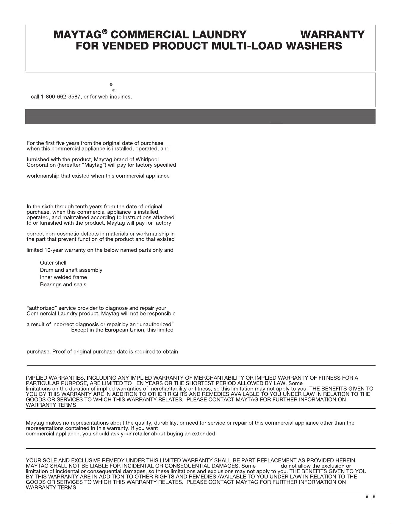
14. Replacement parts during the sixth through tenth years from the date of
original purchase where the commercial appliance is installed, operated
and maintained in a setting other than a vended and/or multi-housing
environment.
15. Replacement parts during the sixth through tenth years from the
date of original purchase where the defective part is not preventing the
functioning of the product.
•
•
•
•
YOUR SOLE AND EXCLUSIVE REMEDY UNDER THIS
LIMITED WARRANTY SHALL BE PART REPLACEMENT AS
PROVIDED HEREIN. Maytag recommends that you use an
under this warranty to provide additional replacement parts as
service company.
warranty is valid only when the commercial appliance is used
in the country in which it was purchased. This limited
warranty is effective from the date of the original consumer
service under this limited warranty.
FIVE YEAR LIMITED WARRANTY
(PARTS ONLY — LABOR NOT INCLUDED)
maintained according to the instructions attached to or
replacement parts to correct defects in materials or
was purchased. This limited warranty does not include labor.
SIXTH THROUGH TENTH YEAR LIMITED WARRANTY
(CERTAIN COMPONENT PARTS ONLY –
LABOR NOT INCLUDED)
specified replacement parts for the following components to
when this commercial appliance was purchased. This is a
does not include labor.
DISCLAIMER OF IMPLIED WARRANTIES
T locations do not allow
.
LIMITATION OF REMEDIES; EXCLUSION OF INCIDENTAL AND CONSEQUENTIAL DAMAGES
locations
.
0 /1
TEN YEAR LIMITED WARRANTY
WHAT IS COVERED
WHAT IS NOT COVERED
DISCLAIMER OF REPRESENTATIONS OUTSIDE OF WARRANTY
a longer or more comprehensive warranty than the limited warranty that comes with this
service plan. The benefits to you given by this warranty are in
addition to other rights and remedies available to you under law in relation to the goods or services to which this warranty relates. Please
contact Maytag for further information on warranty terms.
For written correspondence:
Maytag Commercial Laundry
®
Service Department
2000 N M 63
Benton Harbor, Michigan 49022-2632 USA
IF YOU NEED SERVICE:
Contact your authorized Maytag Commercial Laundry
distributor.
To locate your authorized Maytag Commercial Laundry
distributor,
visit
www.maytagcommerciallaundry.com.
LIMITED
MYS20, MYS30, MYS40, MYS55, MYS65
MYR20, MYR25, MYR30, MYR40, MYR55, MYR65
18
The cost of repair or replacement under these excluded circumstances
shall be borne by the customer.
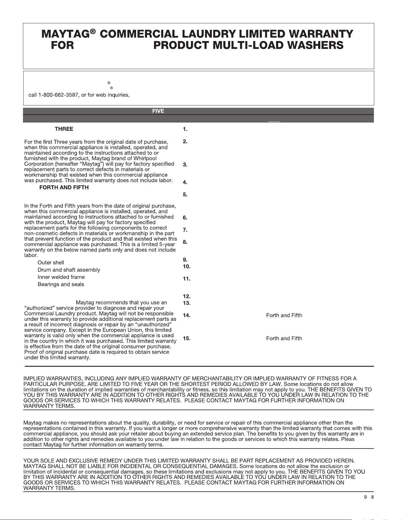
YEAR LIMITED WARRANTY
(PARTS ONLY — LABOR NOT INCLUDED)
All other costs including labor, transportation, shipping, or custom duties
for covered parts.
Factory specified replacement parts if this commercial appliance is
used for other than normal, commercial use or when it is used in a manner
that is inconsistent to published user or operator instructions and/or
installation instructions.
Service calls to correct the installation of your commercial appliance,
to instruct you on how to use your commercial appliance, to replace
or repair house fuses, or to correct external wiring or plumbing.
Service calls to repair or replace appliance light bulbs, air filters, or water
filters. Consumable parts are excluded from warranty coverage.
Damage resulting from improper handling of product during delivery, theft,
accident, alteration, misuse, abuse, fire, flood, acts of God, improper
installation, installation not in accordance with local electrical or plumbing
codes, or use of products not approved by Maytag.
Pick up and delivery. This commercial appliance is designed to be repaired
on location.
Repairs to parts or systems resulting from unauthorized modifications
made to the commercial appliance.
The removal and reinstallation of your commercial appliance if it is installed
in an inaccessible location or is not installed in accordance
with published installation instructions.
Damage resulting from exposure to chemicals.
Changes to the building, room, or location needed in order to make the
commercial appliance operate correctly.
Factory specified replacement parts on commercial appliances with
original model/serial numbers that have been removed, altered, or cannot
be easily determined.
Discoloration, rust, or oxidation of stainless steel surfaces.
Factory specified replacement parts as a result of incorrect diagnosis
or repair by an “unauthorized” service company.
Replacement parts during the years from the date of
original purchase where the commercial appliance is installed, operated
and maintained in a setting other than a vended and/or multi-housing
environment.
Replacement parts during the years from the
date of original purchase where the defective part is not preventing the
functioning of the product.
•
•
•
•
YEAR LIMITED WARRANTY
(CERTAIN COMPONENT PARTS ONLY –
LABOR NOT INCLUDED)
DISCLAIMER OF IMPLIED WARRANTIES
YOUR SOLE AND EXCLUSIVE REMEDY UNDER THIS
LIMITED WARRANTY SHALL BE PART REPLACEMENT AS
PROVIDED HEREIN.
LIMITATION OF REMEDIES; EXCLUSION OF INCIDENTAL AND CONSEQUENTIAL DAMAGES
0 /1
YEAR LIMITED WARRANTY
WHAT IS COVERED
WHAT IS NOT COVERED
DISCLAIMER OF REPRESENTATIONS OUTSIDE OF WARRANTY
e
For written correspondence:
Maytag Commercial Laundry
®
Service Department
2000 N M 63
Benton Harbor, Michigan 49022-2632 USA
IF YOU NEED SERVICE:
Contact your authorized Maytag Commercial Laundry
distributor.
To locate your authorized Maytag Commercial Laundry
distributor,
visit
www.maytagcommerciallaundry.com.
ON-PREMISE
MYS20, MYS30, MYS40, MYS55, MYS65
MYR20, MYR25, MYR30, MYR40, MYR55, MYR65

19
NOTES

20
NOTES

21
NOTES

22
NOTES

NOTES

WFR124390J
04/23
®
/
TM
©2023 Maytag. All rights reserved. Used under license in Canada.