SAFETY INSTRUCTIONS
Before installing the sensor, read the installation and safety
instructions carefully. For reasons of safety and for optimal
operation, we recommend that any maintenance and repair
work be carried out by trained experts only, in accordance with
the guidelines of the vehicle manufacturer. The valves are
safety-relevant parts which are intended for professional
installation only. Failure to do so may result in the failure of the
TPMS sensor. AUTEL does not assume any liability in case of
faulty or incorrect installation of the product.
CAUTION
AUTEL guarantees that the sensor is free from material and
manufacturing defects for a period of twenty-four (24) months
or for 24,000 miles, whichever comes first. AUTEL will at its
discretion replace any merchandise during the warranty period.
The warranty shall be void if any of the following occurs:
1. Improper installation of products
2. Improper usage
3. Induction of defect by other products
4. Mishandling of products
5. Incorrect application
6. Damage due to collision or tire failure
7. Damage due to racing or competition
8. Exceeding specific limits of the product
WARRANTY
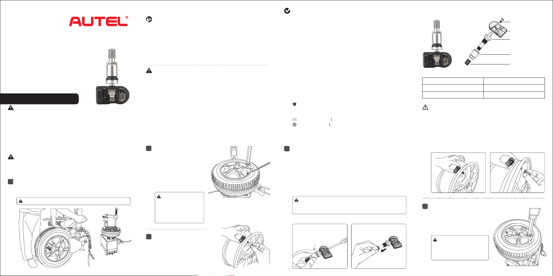
EXPLODED VIEW OF SENSOR
Technical data of the sensor
CAUTION: Each time a tire is serviced or dismounted, or if the
sensor is removed or replaced, it is mandatory to replace the
rubber grommet, screw nut and valve core with our parts to
ensure proper sealing.
It is mandatory to replace the sensor if it is externally damaged.
Correct sensor nut torque: 4.0 Nm.
Weight of sensor without valve 11 g
Dimensions approx. 42.4*24.1*16.0 mm
Max. pressure range 800 kPa
Screw
Cap
Sensor Body
Angle Adjustable 1-Sensor
Metal Valve (Screw-in)
INSTALLATION GUIDE
Loosening the tire
IMPORTANT: Before operating or maintaining this unit, please
read these instructions carefully and pay extra attention to the
safety warnings and precautions. Use this unit correctly and with
care. Failure to do so may cause damage and/or personal injury
and will void the warranty.
Remove the valve cap and core and deflate the tire.
Use the bead loosener to unseat the tire bead.
1
CAUTION: The bead loosener must be facing the valve.
Dismounting the sensor3
Mounting sensor and valve
Step 3 Step 4
4
Place the tire on the rim, make
sure that the valve faces the
separation head at an angle of
180
o
. Mount the tire over the rim.
Mounting the tire
5
CAUTION: The tire should
be mounted to the wheel
using tire changer manuf-
acturer’s instructions.
Dismounting the tire
Clamp the tire onto the tire
changer, and adjust the valve
at 1 o'clock relative to the tire
separation head. Insert the
tire tool and lift the tire bead
onto the mounting head to
dismount the bead.
2
• The TPMS sensor assemblies are replacement or maintenance
parts for vehicles with factory installed TPMS.
• Make sure to program the sensors by AUTEL sensor program-
ming tools by the specific vehicle make, model and year before
installation.
• Do not install programmed TPMS sensors in damaged wheels.
• In order to guarantee optimal function, the sensors may only be
installed with original valves and accessories provided by AUTEL.
• Upon completing the installation, test the vehicle's TPMS
following the procedures described in the original manufactur-
er's user guide to confirm proper installation.
CAUTION:
This starting position
must be o bserved
duri n g the wh o l e
dismounting process.
Remove the screw nut
from the valve stem, and
then remove the sensor
assembly from the rim.
Step1. Connect the sensor body and valve stem at a suitable
angle(Normally use the maximum angle of 30°) and
tighten the screw.
Step2. Remove the screw nut from the valve stem.
Step3. Slide the valve stem through the valve hole of the rim
with the sensor on the inside of the rim.
Step4. Assemble the screw nut back on the valve stem with
4.0 Nm power, then tighten the cap.
Valve stem, rubber
grommet and valve
core assembly
Washer and screw
nut assembly
30°
Step 1 Step 2
Please ensure the sensor
body and valve stem are
firmly connected.
CAUTION:30° is suitable for most rims. If the angle
does not match the rim while installing in step 3, please
loosen the screw then re-operate from step 1.
CUSTOMER & TECH SUPPORT
855-288-3587 (US)
0049 (0) 61032000522 (EU)
0086-755-86147779 (CN)
www.autel.com www.maxitpms.com
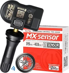
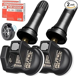
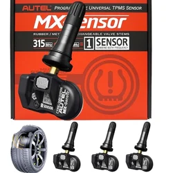
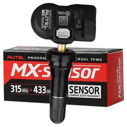
PROGRAMMABLE
UNIVERSAL
TPMS SENSOR
W e b : w w w. a utel.c o m
www.maxitpms.com
• Autel MX-Sensors arrive blank and must be programmed with Autel TPMS
tool, which is recommended to program prior to installation.
• Do not race with the vehicle on which the Clamp-in MX-Sensor is mounted,
and always keep the drive speed under 240km/h.
CAUTION:
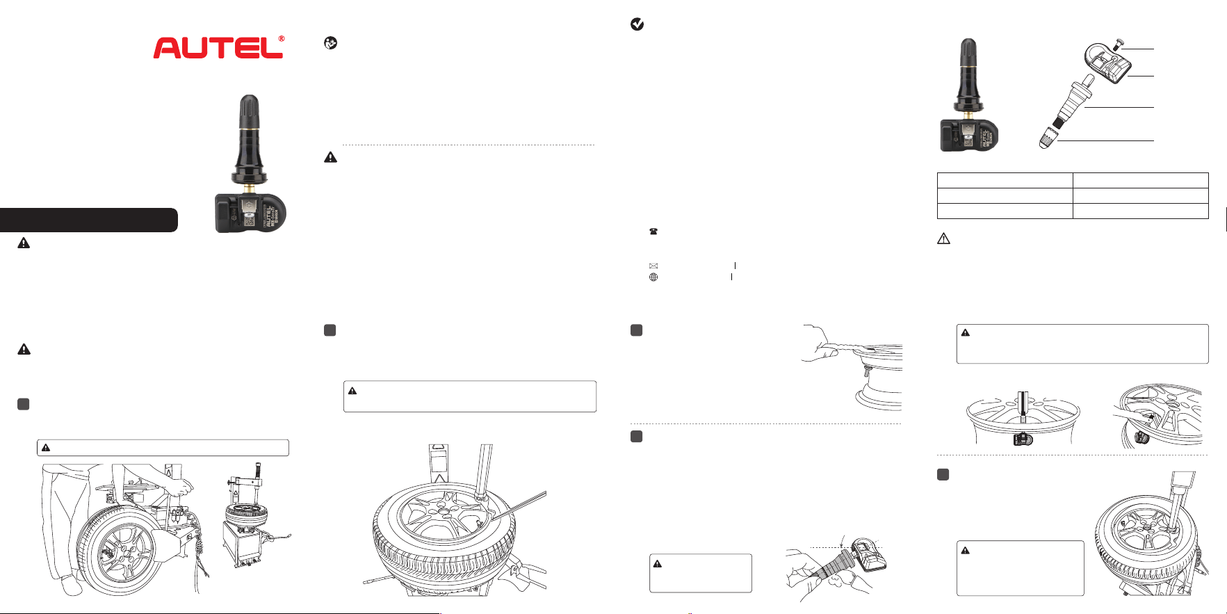
Angle Adjustable 1-Sensor
Rubber Stem (Screw-in)
Sensor body
Screw
Cap
Rubber
valve stem
SAFETY INSTRUCTIONS
Before installing the sensor, read the installation and safety
instructions carefully. For reasons of safety and for optimal
operation, we recommend that any maintenance and repair
work be carried out by trained experts only, in accordance with
the guidelines of the vehicle manufacturer. The valves are
safety-relevant parts which are intended for professional
installation only. Failure to do so may result in the failure of the
TPMS sensor. AUTEL does not assume any liability in case of
faulty or incorrect installation of the product.
• The TPMS sensor assemblies are replacement or maintenance
parts for vehicles with factory installed TPMS.
• Make sure to program the sensors by AUTEL sensor program-
ming tools by the specific vehicle make, model and year before
installation.
• Do not install programmed TPMS sensors in damaged wheels.
• In order to guarantee optimal function, the sensors may only be
installed with original valves and accessories provided by AUTEL.
• Upon completing the installation, test the vehicle's TPMS
following the procedures described in the original manufactur-
er's user guide to confirm proper installation.
CAUTION
AUTEL guarantees that the sensor is free from material and
manufacturing defects for a period of twenty-four (24) months or
for 24,000 miles, whichever comes first. AUTEL will at its
discretion replace any merchandise during the warranty period.
The warranty shall be void if any of the following occurs:
1. Improper installation of products
2. Improper usage
3. Induction of defect by other products
4. Mishandling of products
5. Incorrect application
6. Damage due to collision or tire failure
7. Damage due to racing or competition
8. Exceeding specific limits of the product
WARRANTY
INSTALLATION GUIDE
Loosening the tire
IMPORTANT: Before operating or maintaining this unit, please
read these instructions carefully and pay extra attention to the
safety warnings and precautions. Use this unit correctly and with
care. Failure to do so may cause damage and/or personal injury
and will void the warranty.
Remove the valve cap and core and deflate the tire.
Use the bead loosener to unseat the tire bead.
1
CAUTION: The bead loosener must be facing the valve.
Dismounting the tire
Clamp the tire onto the tire changer, and adjust the valve at 1
o'clock relative to the tire separation head. Insert the tire tool and
lift the tire bead onto the mounting head to dismount the bead.
2
CAUTION: This starting position must be observed during
the whole dismounting process.
3
4
EXPLODED VIEW OF SENSOR
Technical data of the sensor
Weight of sensor without valve
Dimensions
Max. pressure range 800 kPa
Dismounting the sensor
Mounting sensor and valve
Step 1
PROGRAMMABLE
UNIVERSAL
TPMS SENSOR
Place the tire on the rim, make
sure that the valve faces the
separation head at an angle of
180
o
.Mount the tire over the rim.
Mounting the tire
5
CAUTION: The tire should
be mounted to the wheel
using tire changer manuf-
acturer’s instructions.
Step 2 Step 3
11 g
approx. 42.4*24.1*16.0mm
CAUTION:The valve
and rim hole should
be concentric.
CAUTION: Each time a tire is serviced or dismounted, or if the
sensor is removed or replaced, it is mandatory to replace the
rubber valve stem and plastic cap with our parts to ensure
replace the proper sealing. Please ensure the operating
temperature is less than 100℃ (212℉).
30°
Depress the Press button on the
sensor body, carefully pull the sensor
body straight back off the valve. Cut
the rubber bulb and attach a
standard tire valve extractor to the
valve. Remove the valve from the
rim by pulling through the rim.
CAUTION:30° is suitable for most rims. If the angle does
not match the rim after installation, please loosen the
screw and adjust the angle by moving the sensor body.
Step 1.
Connect the sensor body and valve stem at a suitable angle
(Normally use the maximum angle of 30°) and tighten the screw.
Apply tire soap or lube solution to the rubber valve stem.
Step 2. Line the sensor up with the rim hole and attach a
standard tire valve extractor to the end of of the valve.
Step 3. Pull the valve stem straight through the valve hole, then
assemble the cap back. Note the rubber bulb of the valve
resting against the rim.
CAUTION:
• Autel MX-Sensors arrive blank and must be programmed with Autel TPMS
tool, which recommended to program prior to installation.
• Do not race with the vehicle on which the Snap-in MX-Sensor is mounted,
and always keep the drive speed under 210 km/h.
W e b : w w w. a utel.c o m
www.maxitpms.com
CUSTOMER & TECH SUPPORT
855-288-3587 (US)
0049 (0) 61032000522 (EU)
0086-755-86147779 (CN)
www.autel.com www.maxitpms.com