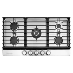
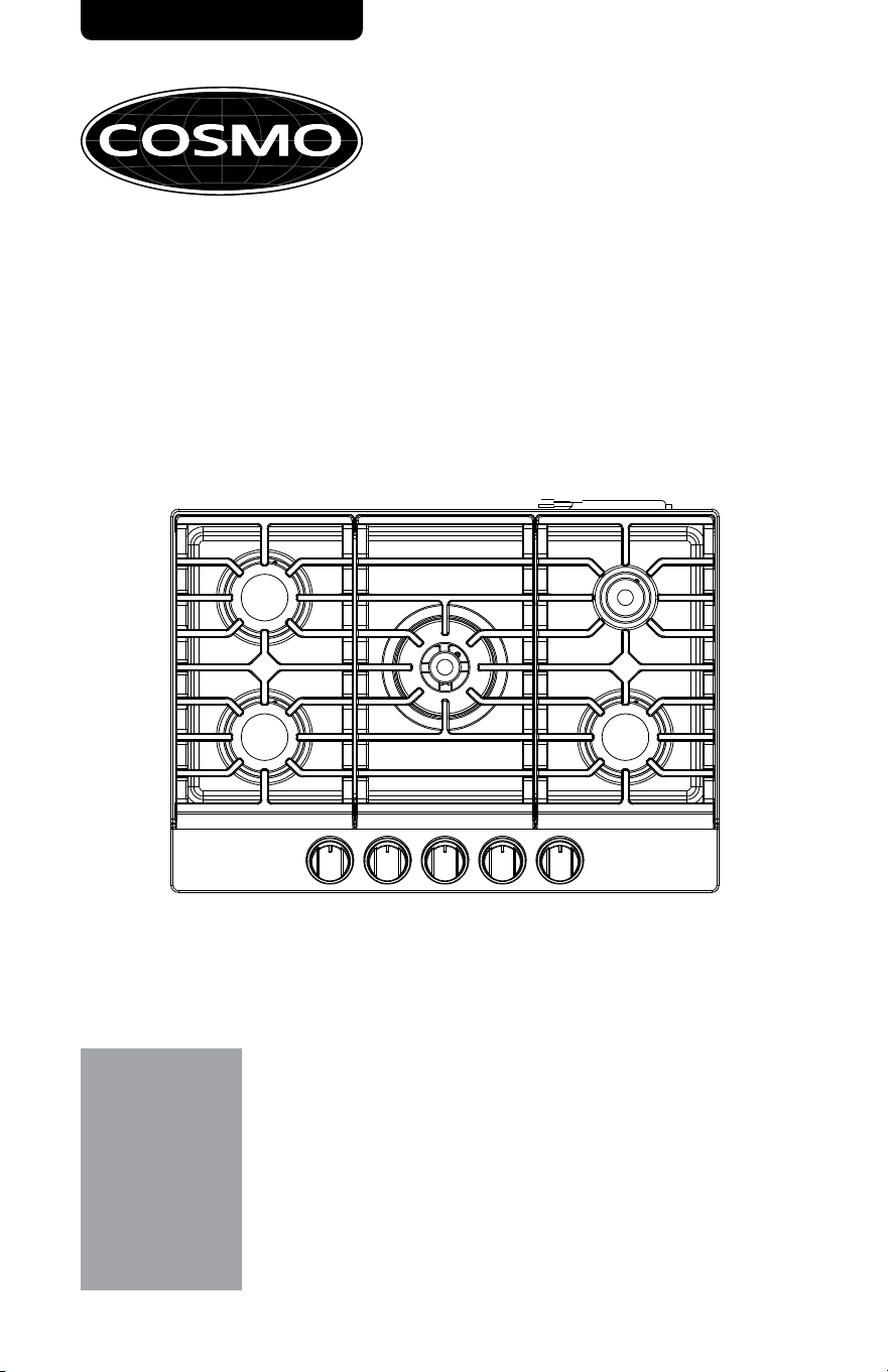
GAS COOKTOP
INSTALLATION & USER MANUAL
READ AND SAVE THESE INSTRUCTIONS.
FOR RESIDENTIAL USE ONLY.
PLEASE LEAVE THIS GUIDE WITH THE HOMEOWNER.
PLEASE KEEP THIS GUIDE FOR FUTURE REFERENCE.
IMPORTANT:
INSTALLER:
HOMEOWNER:
DROP-IN COOKTOP SERIES
COS-CTGH305SS
COS-CTGH365SS
Rev.25.12
THANK YOU FOR YOUR PURCHASE
Thank you for your purchase. We know that you have many brands and
products to choose from and we are honored to know that you have decided
to take one of our products into your home and hope that you enjoy it.
COSMO Appliances are designed according to the strictest safety and
performance standard for the North American market. We follow the most
advanced manufacturing philosophy. Each appliance leaves the factory after
thorough quality inspection and testing. Our distributors and our service
partners are ready to answer any questions you may have regarding how to
install, use and case for your products. We hope that this manual will help you
learn to use the product in the safest and most effective manner.
Before using this product, please read through this manual carefully. Keep
this user manual in a safe place for future reference. Please ensure that other
persons using this product are familiar with these instructions as well.
If you have any questions or concerns, please contact the dealer from whom you
purchased the product, or contact our Customer Support at:
1-888-784-3108
Reach us online at:
www.cosmoappliances.com
2
TABLE OF CONTENTS
COOKTOP SAFETY ............................................................................................. 4
Important Safety Instructions ................................................................................. 7
INSTALLATION REQUIREMENTS ...................................................................... 10
Tools and Parts ........................................................................................................ 10
Location Requirements ........................................................................................... 12
Product Dimensions ................................................................................................. 13
Clearances ................................................................................................................. 15
Cutout Dimensions ................................................................................................... 16
Electrical Requirements ........................................................................................... 17
Gas Supply Requirements ...................................................................................... 18
INSTALLATION INSTRUCTIONS ........................................................................ 21
Unpack Cooktop....................................................................................................... 21
Install Cooktop ......................................................................................................... 22
Gas Connection ....................................................................................................... 23
Complete Connection ............................................................................................ 25
Adjust Flame Height ............................................................................................... 27
GAS CONVERSION ........................................................................................... 29
Convert Gas Pressure Regulator .......................................................................... 29
Convert Surface Burners ......................................................................................... 31
Complete Gas Conversion ..................................................................................... 33
OVERVIEW ........................................................................................................ 34
COOKTOP USE ................................................................................................... 36
Power Failure ........................................................................................................... 37
Cookware ................................................................................................................. 38
COOKTOP CARE ............................................................................................... 39
TROUBLESHOOTING ......................................................................................... 41
LIMITED WARRANTY ........................................................................................ 43
3
Fire Hazard
If the information in this manual is not followed exactly, a fire or explosion
may result causing property damage, personal injury or death.
WARNING
Never Operate the Top Surface Cooking Section of this Appliance
Unattended.
DO NOT ATTEMPT TO EXTINGUISH AN OIL/GREASE FIRE WITH WATER
COOKTOP SAFETY
WARNING
- Do not store or use gasoline or other flammable vapors and liquids in
the vicinity of this or any other appliance.
- WHAT TO DO IF YOU SMELL GAS
• Do not try to light any appliance.
• Do not touch any electrical switch.
• Do not use any phone in your building.
• Clear the room, building, or area of all occupants.
• Immediately call your gas supplier from a neighbor's phone. Follow
the gas supplier's instructions.
• If you cannot reach your gas supplier, call the fire department.
- Installation and service must be performed by a qualified installer,
service agency or the gas supplier.
• Failure to follow this warning statement could result in fire, explosion, or
burn hazard that could cause property damage, personal injury, or
death.
• If a fire should occur, keep away from the appliance and immediately
call your fire department.
4
WARNING: Gas leaks cannot always be detected by smell.
Gas suppliers recommend that you use a gas detector approved by UL or
CSA.
For more information, contact your gas supplier.
WARNING: Do not install a ventilation system that blows air downward
toward this cooking appliance. This type of ventilation system may cause
ignition and combustion problems with this cooking appliance resulting in
personal injury or unintended operation.
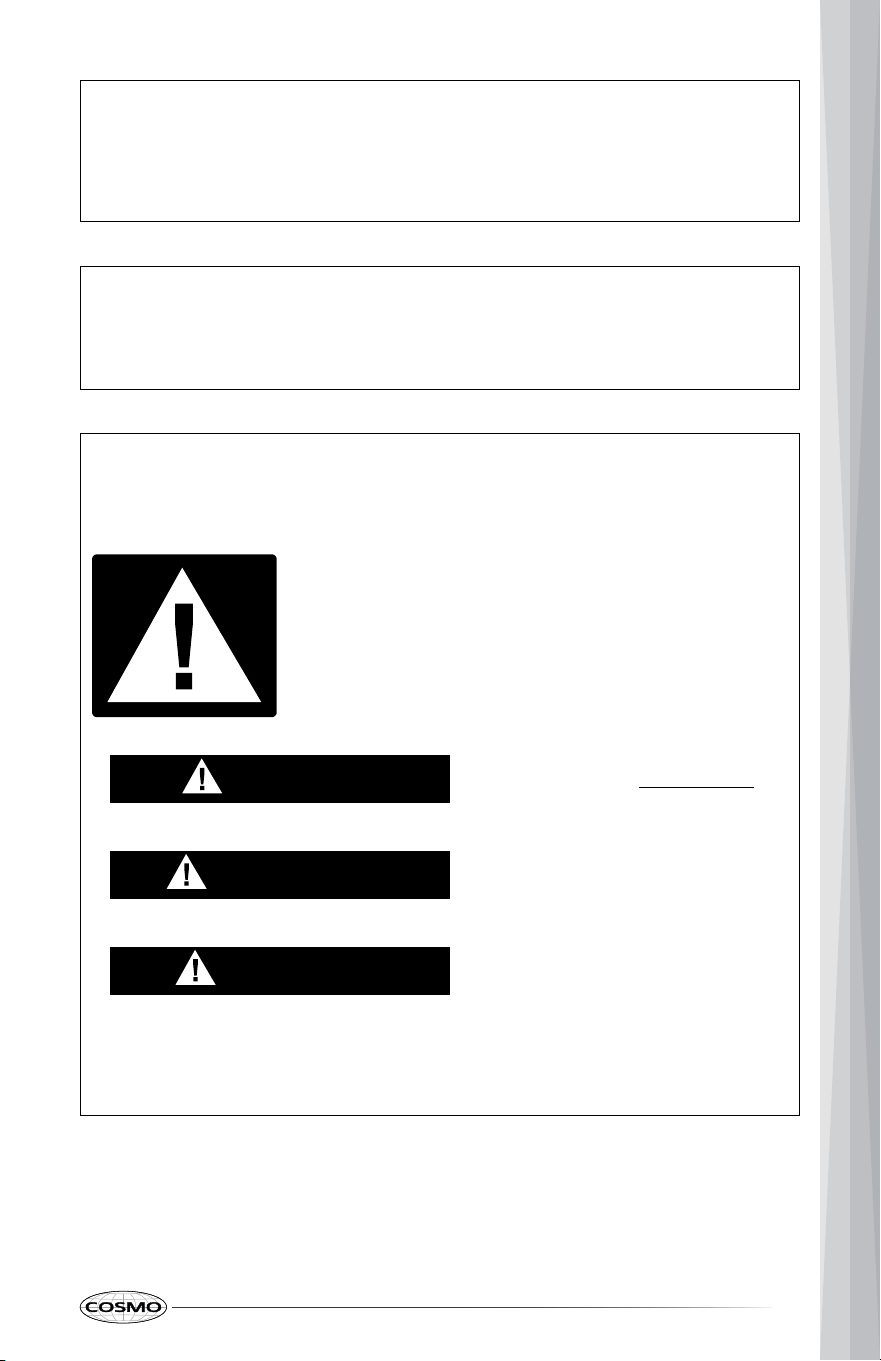
Your safety and the safety of others are very important.
We have provided many important safety messages in this manual and on
your appliance. Always read and obey all safety messages.
This is the safety alert symbol.
This symbol alerts you to potential hazards that can
kill or hurt you and others.
All safety messages will follow the safety alert symbol
and either the word "DANGER," "WARNING" or
"CAUTION." These words mean:
DANGER
WARNING
You can be killed or seriously
injured if you don't immediately
follow instructions.
You can be killed or seriously
injured if you don't follow
instructions.
A potentially hazardous situation
which, if not avoided, could result
in minor or moderate injury.
CAUTION
All safety messages will tell you what the potential hazard is, tell you how
to reduce the chance of injury, and tell you what can happen if the
instructions are not followed.
5
In the State of Massachusetts, the following installation instructions apply:
• Installations and repairs must be performed by a qualified or licensed
contractor, plumber, or gasfitter qualified or licensed by the State of
Massachusetts.
• If using a ball valve, it shall be a T-handle type.
• A flexible gas connector, when used, must not exceed 3 feet.
6
California Proposition 65 Warning
WARNING:
Cancer and Reproductive Harm - www.P65Warnings.ca.gov.
READ AND SAVE
TH
ESE INSTRUCTIO
NS
IMPORTANT SAFETY
INSTRUCTIONS
WARNING: To reduce the risk of fire, electrical shock, injury to persons, or
damage when using the cooktop, follow basic precautions, including the
following:
• WARNING: NEVER use this
appliance as a space heater to
heat or warm the room. Doing so
may result in carbon monoxide
poisoning and overheating of the
oven.
• Do not touch any part of the
cooktop, including but not limited
to cooktop burners during or
immediately after cooking.
• CAUTION: Do not store items of
interest to children in cabinets
above the cooktop – children
climbing on the cooktop to reach
items could be seriously injured.
• Do Not Leave Children Alone –
Children should not be left alone
or unattended in area where
appliance is in use. They should
never be allowed to sit or stand
on any part of the appliance.
• Wear Proper Apparel – Loose-
fitting or hanging garments
should never be worn while using
the appliance.
• User Servicing – Do not repair or
replace any part of the appliance
unless specifically recommended
in the manual. All other servicing
should be referred to a qualified
technician.
• Storage in or on appliance –
Flammable materials should not
be stored in an oven or near
surface units.
• Do Not Use Water on Grease
Fires – Smother fire or flame or
use dry chemical or foam-type
extinguisher.
• Use Only Dry Potholders – Moist
or damp potholders on hot
surfaces may result in burns from
steam. Do not let potholder touch
hot surface units. Do not use a
towel or other bulky cloth.
• Never Leave Surface Units
Unattended at High Heat
Settings – Boilover causes
smoking and greasy spillovers
that may ignite.
• Glazed Cooking Utensils – Only
certain types of glass,
glass/ceramic, ceramic,
earthenware, or other glazed
utensils are suitable for range-
top service without breaking due
to the sudden change in
temperature.
7
READ AND SAVE
TH
ESE INSTRUCTIO
NS
IMPORTANT SAFETY
INSTRUCTIONS
• Utensil Handles Should Be Turned
Inward and Not Extend Over
Adjacent Surface Units – To
reduce the risk of burns, ignition
of flammable materials, and
spillage due to unintentional
contact with the utensil, the
handle of a utensil should be
positioned so that it is turned
inward, and does not extend over
adjacent surface units.
• Make sure the cooktop hold-
down brackets are properly
installed.
• Disconnect the electrical supply
before servicing.
• Do not use replacement parts
that have not been
recommended by the
manufacturer (e.g. parts made at
home using a 3D printer).
• Clean Cooktop With Caution – If
a wet sponge or cloth is used to
wipe spills on a hot cooking area,
be careful to avoid steam burn.
Some cleaners can produce
noxious fumes if applied to a hot
surface.
• Do Not Heat Unopened Food
Containers – Build-up of pressure
may cause container to burst and
result in injury.
• Proper Installation – The
appliance, when installed, must
be electrically grounded in
accordance with local codes, or
in the absence of local codes,
with the National Electrical Code,
ANSI/NFPA 70 or the Canadian
Electrical Code, CSA C22.1-02. In
Canada, the appliance must be
electrically grounded in
accordance with Canadian
Electrical Code. Be sure your
appliance is properly installed
and grounded by a qualified
technician.
• This cooktop is equipped with a
three-prong grounding plug for
your protection against shock
hazard and should be plugged
directly into a properly grounded
receptacle. Do not cut or remove
the grounding prong from this
plug.
• Disconnect the electrical supply
before servicing.
• Injuries may result from misuse of
the cooktop such as stepping,
leaning, or sitting on the top
surface.
• Maintenance – Keep cooktop
area clear and free from
combustible materials, gasoline,
and other flammable vapors and
liquids.
8
READ AND SAVE
TH
ESE INSTRUCTIO
NS
IMPORTANT SAFETY
INSTRUCTIONS
• Do not let cooking grease or
other flammable materials
accumulate on the cooktop.
Grease on the cooktop may
ignite.
• Top burner flame size should be
adjusted so it does not extend
beyond the edge of the cooking
utensil. This instruction is based
on safety considerations.
• Have the installer show you the
location of the cooktop gas shut-
off valve and how to turn it off if
necessary.
• Proper Disposal of Your
Appliance – Dispose of or recycle
your appliance in accordance
with Federal and Local
Regulations. Contact your local
authorities for the
environmentally safe disposal or
recycling of your appliance.
For units with ventilating hoods:
• Clean Ventilating Hoods
Frequently – Grease should not
be allowed to accumulate on
hood or filter.
• When flaming foods under the
hood, turn the fan on.
9
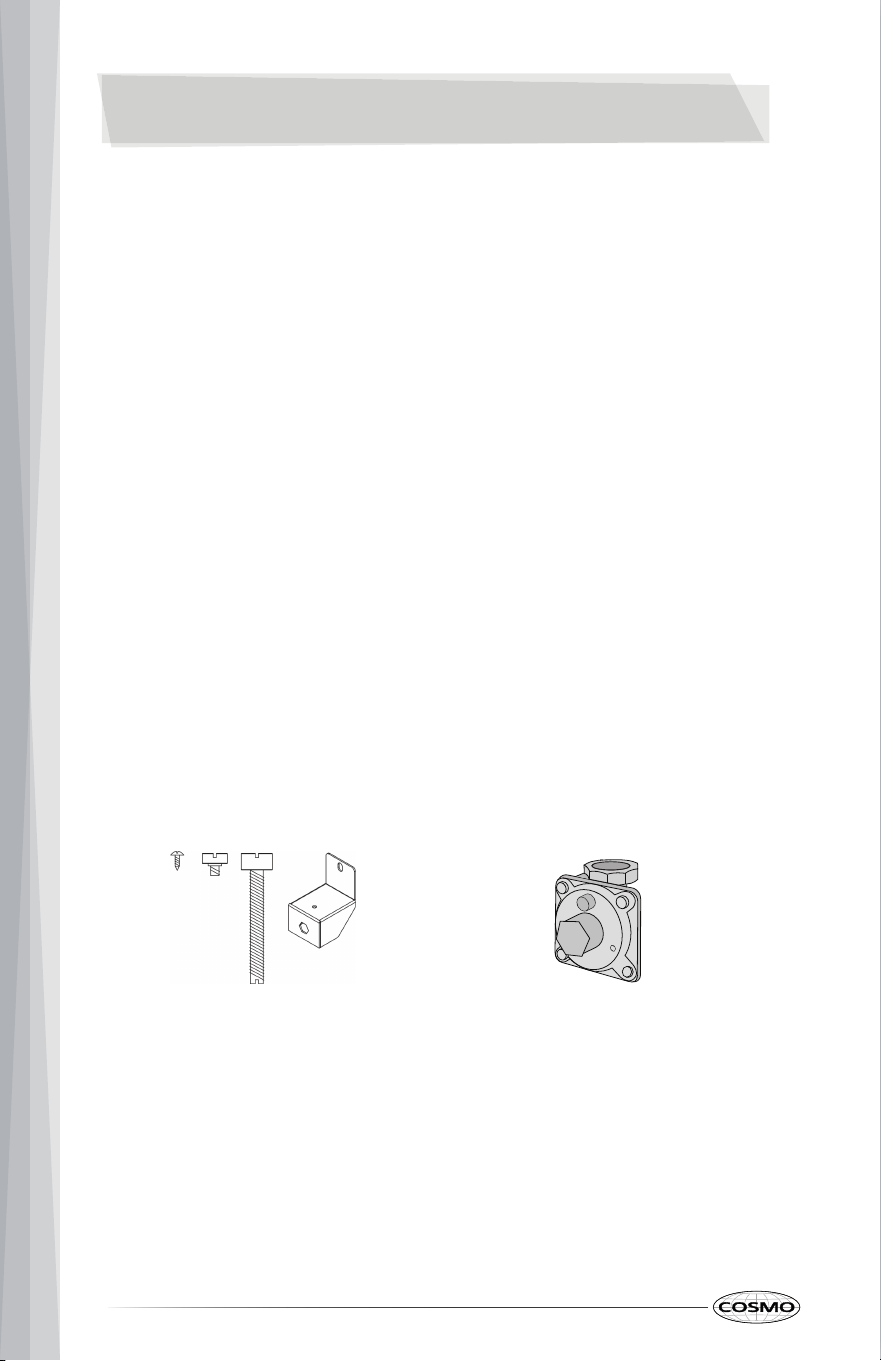
Parts Supplied
Hold-down bracket with screws
(4 sets)
INSTALLATION REQUIREMENTS
• Tape measure
• Flat-blade screwdriver
• Phillips screwdriver
• Wrench or pliers
• Pipe wrench
• 15/16" (2.4 cm) combination
wrench
• Marker or pencil
• Pipe-joint compound resistant to
Propane gas
• Noncorrosive leak-detection
solution
For Propane/Natural Gas Conversions
• 1/2" (1.3 cm) combination wrench
• 1/4" (6 mm) nut drive
• 9/32" (7 mm) nut drive
• Masking tape
TOOLS AND PARTS
Gather the required tools and parts before starting installation. Read and
follow the instructions provided with any tools listed here.
Tools Needed
10
Gas pressure regulator
Parts Needed
Scan to find
available NG/LP
kits
Optional Parts
To purchase these or any other accessories, please visit
www.cosmoappliances.com or reference the contact information at the end
of this manual.
• Replacement NG/LP conversion kit
11
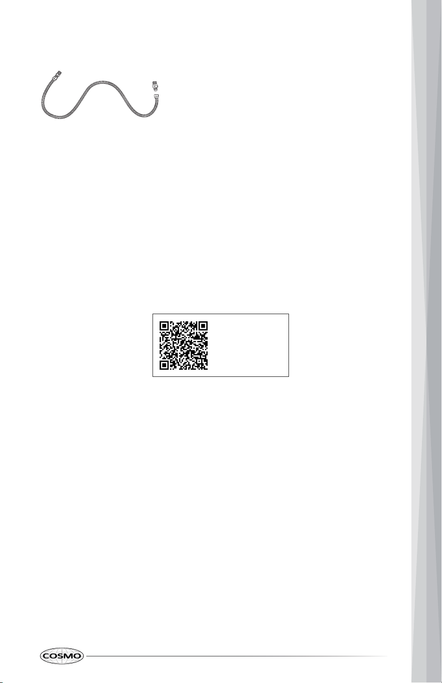
Gas supply line kit
(supply line and 2 adapters)

• This cooktop is for indoor household use only.
• It is the installer's responsibility to comply with installation clearances
specified on the model/serial rating plate. The model/serial rating plate is
located on the underside of the cooktop base.
• The cooktop should be installed in a location away from strong draft
areas, such as windows, doors, and strong heating vents or fans.
• All openings in the wall or floor where cooktop is to be installed must be
sealed.
• Cabinet opening dimensions that are shown must be used.
• Grounded electrical supply is required. See "Electrical Requirements"
section.
• Proper gas supply connection must be available. See "Gas Supply
Requirements" section.
• The cooktop is designed to hang from the countertop by its side or rear
flanges.
• The gas and electric supply should be accessible without requiring
removal of the cooktop.
IMPORTANT: To avoid damage, check with your builder or cabinet supplier to
make sure that the materials used will not discolor, delaminate or sustain
other damages.
Mobile Home - Additional Installation Requirements
• The installation of this cooktop must conform to the Manufactured Home
Construction and Safety Standard, Title 24 CFR, Part 3280 (formerly the
Federal Standard for Mobile Home Construction and Safety, Title 24, HUD
Part 280). When such standard is not applicable, use the Standard for
Manufactured Home Installations, ANSI A225.1/NFPA 501A or with local
codes.
In Canada, the installation of this cooktop must conform with the current
standards CAN/CSA-Z240-latest edition, or with local codes.
LOCATION REQUIREMENTS
IMPORTANT: Observe all governing codes and ordinances. Do not obstruct
flow of combustion and ventilation air.
12
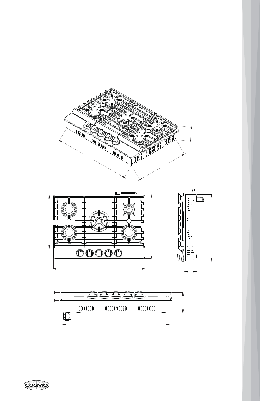
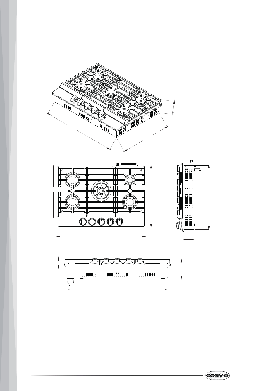
COS-CTGH305SS
PRODUCT DIMENSIONS
Note: Cooktop features may differ.
287⁄₁₆” (722 mm)
57⁄₁₆” (137.8 mm)
199⁄₁₆” (496.9 mm)
21” (533 mm)
30” (762 mm)
171⁄₄” (437.9 mm)
199⁄₁₆” (497.5 mm)
31⁄₈” (79.8 mm)
21⁄₁₆” (53 mm)
57⁄₁₆” (137.8 mm)
287⁄₁₆” (722 mm)
13
COS-CTGH365SS
51⁄₄” (132.8 mm)
199⁄₁₆” (497.5 mm)
343⁄₈” (873.5 mm)
171⁄₄” (437.9 mm)
31⁄₈” (79.8 mm)
3515⁄₁₆” (913.3 mm)
21”” (533 mm
199⁄₁₆” (497.5 mm)
51⁄₄” (132.8 mm)
21⁄₁₆” (53 mm)
343⁄₈” (873.5 mm)
14
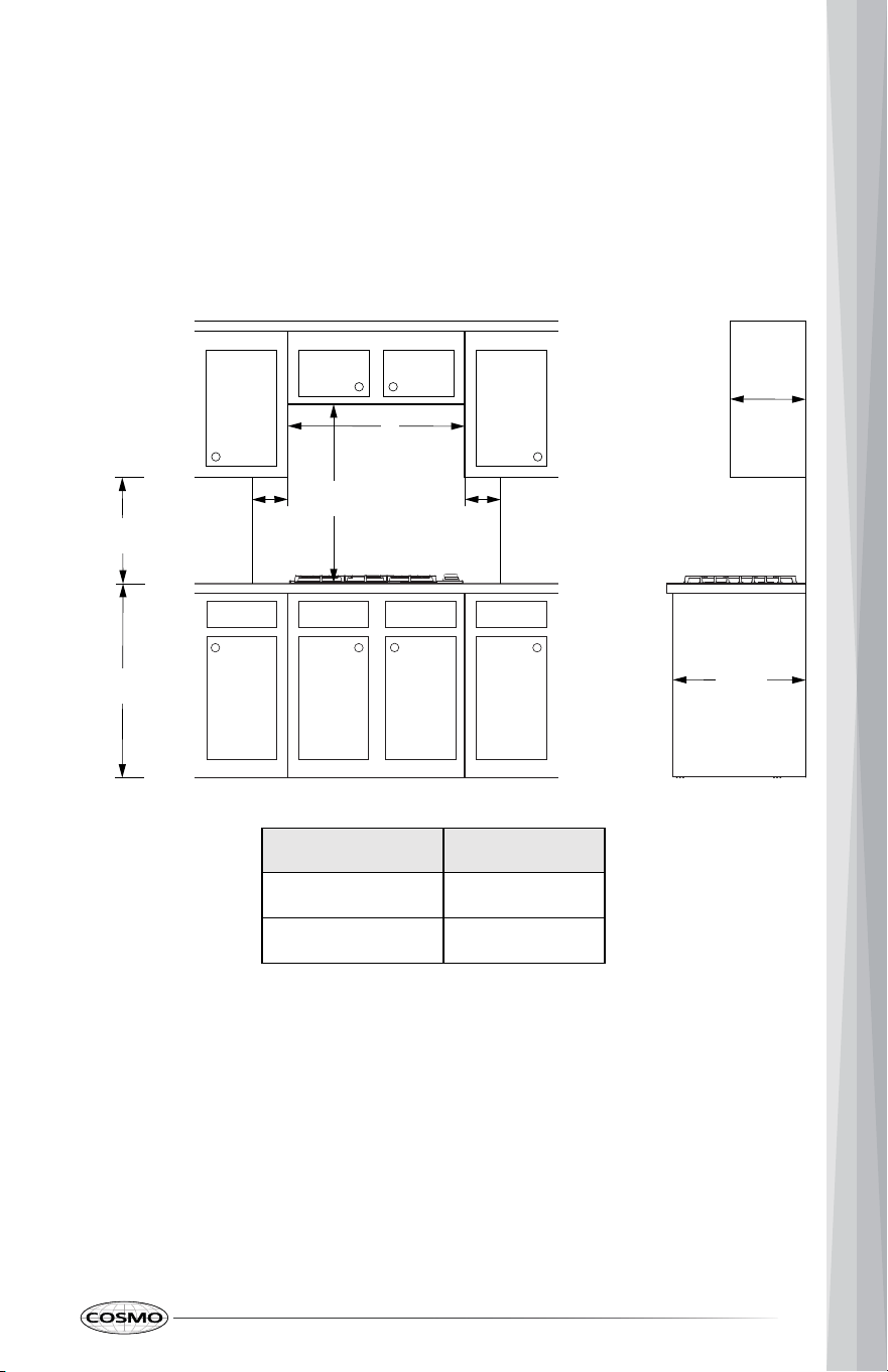
24 in
(610 cm)
Lower
Cabinet
Depth
13 in
(33 cm)
Maximum
36 in
(91.4 cm)
18 in
(45.7 cm)
30 in
(76.2 cm)
A
6 in
(15.2 cm)
to right
wall
6 in
(15.2 cm)
to left
wall
Overhead
Cabinet
Depth
CLEARANCES
IMPORTANT: Some cabinet and building materials are not designed to
withstand the heat produced by the cooktop. Check with your builder or
cabinet supplier to make sure that the materials used will not discolor,
delaminate or sustain other damage.
GIVEN DIMENSIONS ARE MINIMUM CLEARANCES.
MODEL A
COS-CTGH305SS
30" (76.2 cm)
COS-CTGH305SS
36" (91.4 cm)
NOTE:
• 30" (76.2 cm) minimum clearance between cooking surface and bottom
of the overhead cabinet.
IMPORTANT: If installing a range hood, hood liner, or microware hood
combination above the cooking surface, follow the range hood or
microwave hood combination installation instructions for dimensional
clearances above the cooktop surface.
• 18" (45.7 cm) minimum clearance from upper cabinet to countertop on
either side of unit.
15
Back Wall
D
B
Side Wall
A
C
Side Wall
F
G
E
Countertop Front Edge
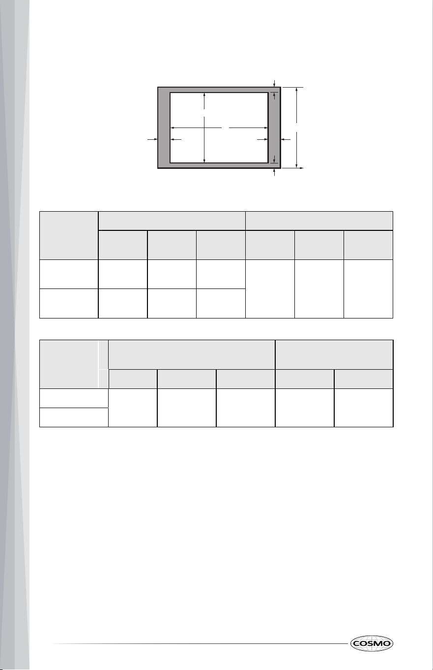
CUTOUT DIMENSIONS
MODEL
A B
Min
Recom-
mended
Max Min
Recom-
mended
Max
COS-CTGH305SS
28
9
/
16
"
(72.6 cm)
29"
(73.6 cm)
29
3
/
8
"
(74.6 cm)
19
1
/
4
"
(48.9 cm)
19
3
/
4
"
(50.1 cm)
20
3
/
16
"
(51.3 cm)
COS-CTGH365SS
34
9
/
16
"
(87.8 cm)
34
15
/
16
"
(88.9 cm)
35
3
/
8
"
(89.8 cm)
MODEL
Back Wall and Countertop Front
Side Walls
(Combustible Surfaces)
C D E F G
COS-CTGH305SS
24"
(61.0 cm)
2.5"
(6.35 cm)
2.5"
(6.35 cm)
6"
(15.2 cm)
6"
(15.2 cm)
COS-CTGH365SS
NOTE:
• After making the countertop cutout, some installations may require
notching down the base cabinet side walls to clear the cooktop base. To
avoid this modification, use a base cabinet with sidewalls wider than the
cutout.
• If a built-in wall oven is to be installed below this cooktop, the grounded
outlet and gas supply piping must be located in an adjacent cabinet. If
installing a range hood or microwave hood combination above the
cooking surface, follow the range hood or microwave hood combination
installation instructions for dimensional clearances above the cooktop.
• This cooktop and its gas and electrical supply sources must be installed
before the undercounter built-in wall oven is installed.
16
WARNING
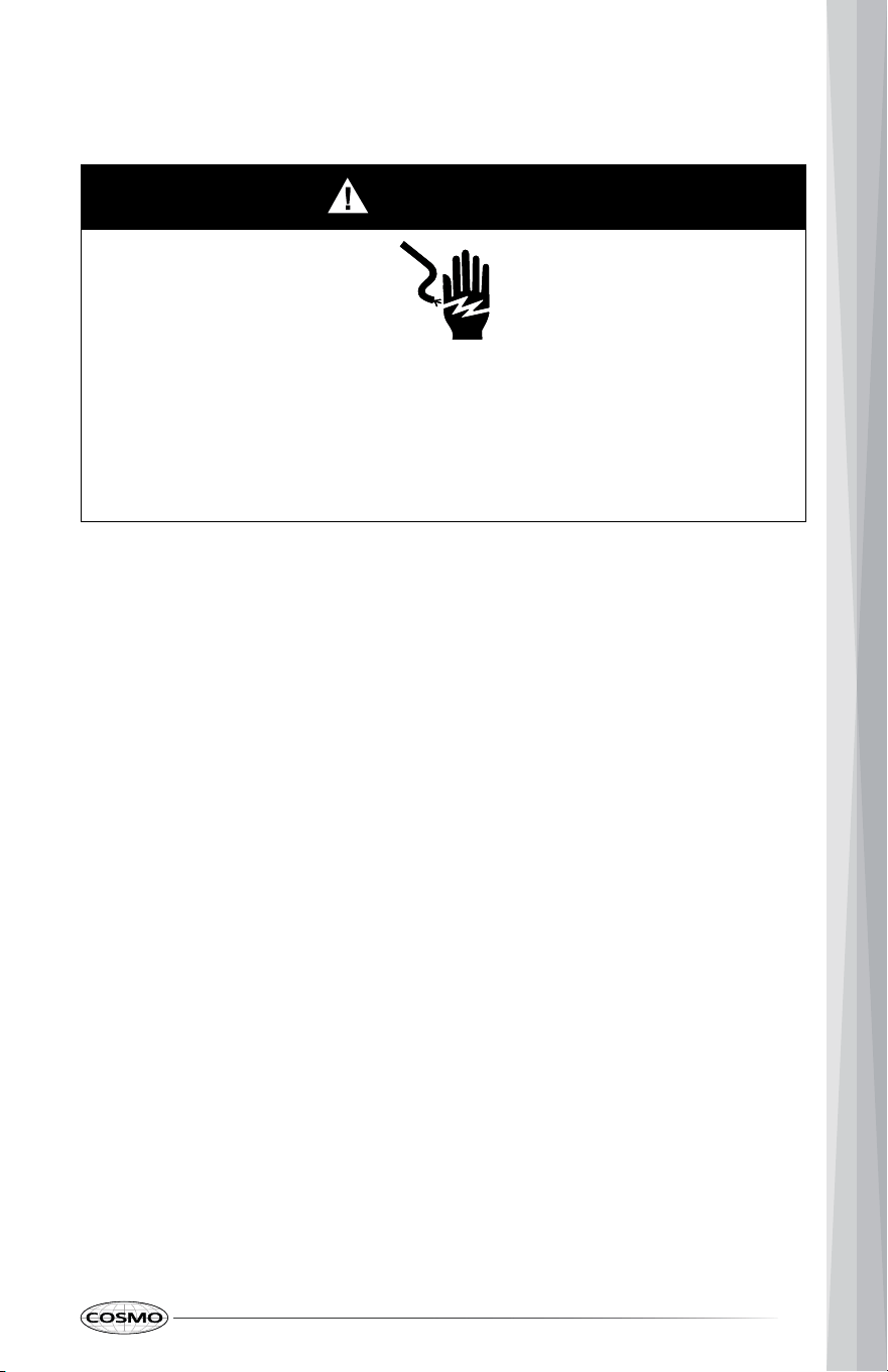
Electrical Shock Hazard
Plug into a grounded 3 prong outlet.
Do not remove ground prong.
Do not use an adapter or extension cord.
Failure to do so can result in death, fire or electrical shock.
IMPORTANT: The cooktop must be electrically grounded in accordance with
local codes and ordinances, or in the absence of local codes, with the
National Electrical Code, ANSI/NFPA 70 or Canadian Electrical Code, CSA
C22.1.
Do not ground the cooktop to any gas line or gas pipe.
This cooktop is equipped with an electronic ignition system that will not
operate if plugged into an outlet that is not proper polarized.
If codes permit and a separate ground wire is used, it is recommended that a
qualified electrical installer determine that the ground path is adequate and
wire gauge is in accordance with local codes.
A copy of the above code standards can be obtained from:
National Fire Protection Association
1 Batterymarch Park
Quincy, MA 02169-7471
CSA International
8501 East Pleasant Valley Road
Cleveland, OH 44131-5575
A 120 V, 60 Hz, AC only, 15 A, fused electrical circuit is required. A time-delay
fuse or circuit breaker is also recommended. It is recommended that a
separate circuit serving only this cooktop is provided.
ELECTRICAL REQUIREMENTS
17
Explosion Hazard
Use a new CSA International approved gas supply line and install a shut-
off valve for new installations.
Securely tighten all gas connections.
If connected to LP, have a qualified person make sure gas pressure does
not exceed the maximum pressure listed in this section.
Examples of a qualified person include:
Failure to do so can result in death, explosion or fire.
IMPORTANT:
• Observe all governing codes and ordinances.
• This installation must conform with all local codes and ordinances. In the
absence of local codes, installation must conform with National Fuel Gas
Code, ANSI Z223.1/NFPA 54 or, in Canada, the Natural Gas and Propane
Installation Code, CSA B149.1 - latest edition.
• Cooktop must be connected to a regulated gas supply.
Electronic ignition systems operate within wide voltage limits, but proper
grounding and polarity are necessary. Check that the outlet provides 120 V
power and is correctly grounded.
WARNING: Improper connection of the equipment-grounding conductor can
result in a risk of electric shock. Check with a qualified electrician or service
technician if you are in doubt as to whether the appliance is properly
grounded. Do not modify the power supply cord plug. If it will not fit the
outlet, have a proper outlet installed by a qualified electrician.
GAS SUPPLY REQUIREMENTS
WARNING
• licensed heating personnel,
• authorized gas company personnel, and
• authorized service personnel.
18
• Leak testing of the cooktop must be conducted according to the
manufacturer's instructions.
TYPE OF GAS
Natural Gas:
This cooktop is factory-set for use with Natural gas. The model/serial rating
plate located on the underside of the cooktop base has information on the
types of gas that can be used. If the types of gas listed do not include the type
of gas available, check with the local gas supplier.
LP Gas Conversion:
Conversion must be performed by a qualified service technician. The qualified
agency performing this work assumes the gas conversion responsibility.
No attempt shall be made to convert the appliance from the gas specified on
the model/serial rating plate for use with a different gas without consulting
the serving gas supplier. See "GAS CONVERSION" section.
GAS SUPPLY LINE
Provide a gas supply line of 3/4" (1.9 cm) rigid pipe to the cooktop location. A
smaller size pipe on longer runs may result in insufficient gas supply. Pipe-joint
compounds that resist the action of LP gas must be used. With LP gas, piping
or tubing size can be 1/2" (1.3 cm) minimum. Usually, LP gas suppliers
determine the size and materials used in the system.
IMPORTANT: All connections must be wrench-tightened. Do not make
connections to the gas pressure regulator too tight. Making the connections
too tight may crack the regulator and cause a gas leak. Do not allow the
regulator to turn or move when tightening fittings.
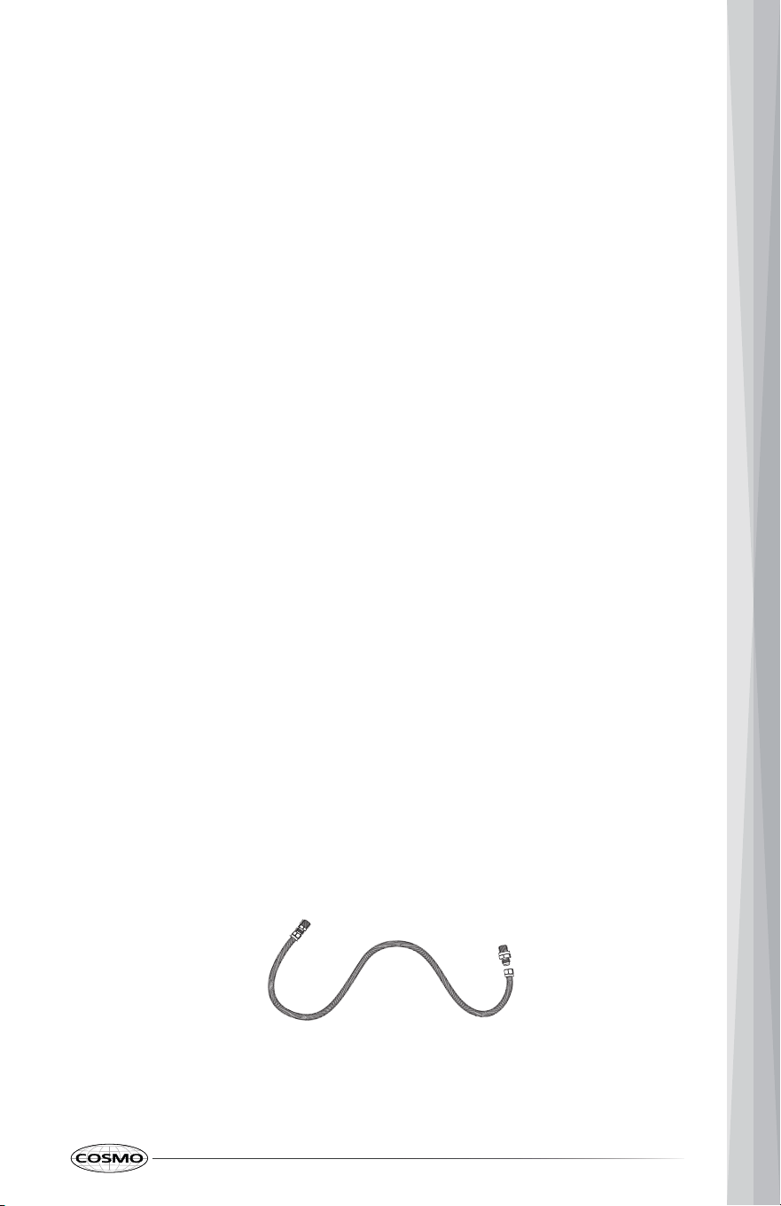
Flexible metal appliance connector:
• If local codes permit, a new CSA design-certified, 4 - 5 ft (122 - 152.4 cm)
long, 1/2" (1.3 cm) or 3/4" (1.9 cm) I.D., flexible metal appliance connector
may be used for connecting cooktop to the gas supply line.
• A 1/2" (1.3 cm) male pipe thread is needed for connection to the female
pipe threads of the inlet to the appliance pressure regulator.
• Do not kink or damage the flexible metal tubing when moving the
cooktop.
19
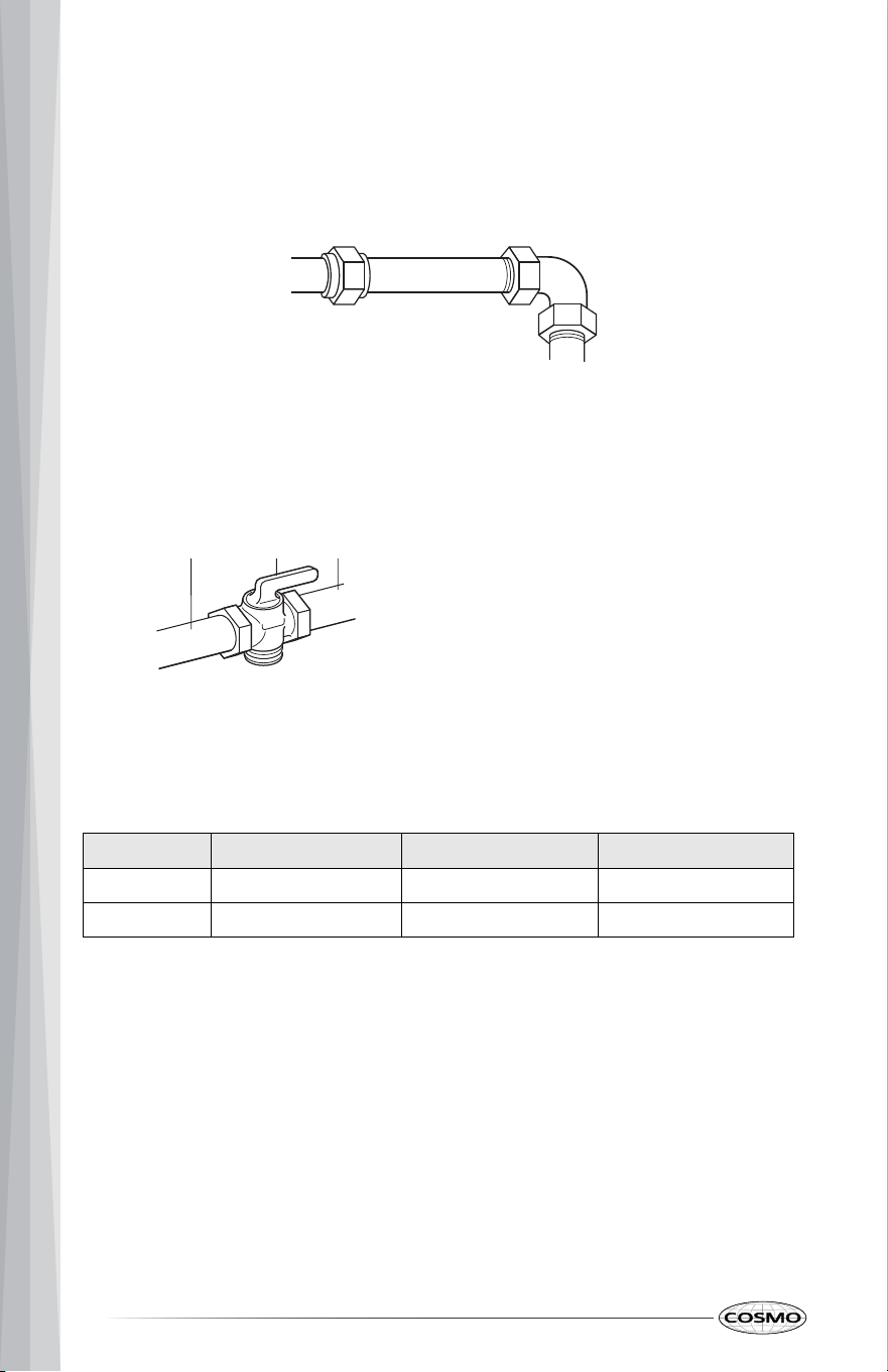
Rigid pipe connection:
The rigid pipe connection requires a combination of pipe fittings to obtain an
in-line connection to the cooktop. The rigid pipe must be level with the
cooktop connection. All strains must be removed from the supply and fuel
lines so cooktop will be level and in line.
Gas shutoff valve:
A manual gas line shut-off valve must be installed in an easily accessible
location. Do not block access to shut-off valve. The valve is for turning on or
shutting off gas to the cooktop.
GAS PRESSURE REGULATOR
The gas pressure regulator supplied with this cooktop must be used. The inlet
pressure to the regulator should be as follows for proper operation:
TYPE OF GAS
MANIFOLD PRESSURE MINIMUM PRESSURE
N
atural gas
5
" WCP
5
" WCP
L
P gas
10"
WCP
10" WCP
Contact local gas supplier if you are not sure about the inlet pressure.
Burner Input Requirements
Input ratings shown on the model/serial rating plate are for elevations up to
2,000 ft (609.6 m).
For elevations above 2,000 ft (609.6 m), ratings are reduced at a rate of 4%
for each 1,000 ft (304.8 m) above sea level (not applicable for Canada).
a
b
c
Gas supply line
Shutoff valve "open" position
To cooktop
MAXIMUM PRESSURE
10" WCP
13" W
CP
20
a b c
WARNING
Excessive Weight Hazard
Use two or more people to move and install cooktop.
Failure to do so can result in back or other injury.
GAS SUPPLY PRESSURE TESTING
Gas supply pressure for testing regulator must be at least 1" (2.5 cm) water
column pressure above the manifold pressure shown on the model/serial
rating plate.
Line pressure testing above 0.5 psi gauge (14" WCP)
The cooktop and its individual shutoff valve must be disconnected from the
gas supply piping system during any pressure testing of that system at test
pressures in excess of 0.5 psi (3.5 kPa).
Line pressure testing at 0.5 psi gauge (14" WCP) or lower
The cooktop must be isolated from the gas supply piping system by closing its
individual manual shutoff valve during any pressure testing of the gas supply
piping system at test pressures equal to or less than 1/2 psi (3.5 kPa).
INSTALLATION INSTRUCTIONS
IMPORTANT: This appliance shall be installed only by authorized persons and
in accordance with the manufacturer's installation instructions, local gas
fitting regulations, municipal building codes, electrical wiring regulations,
local water supply regulations.
UNPACK COOKTOP
1. Remove shipping materials, tape and film from the cooktop. Do not
dispose of anything until the installation is complete.
2. Set aside the surface burners and grates if they are not pre-installed.
21
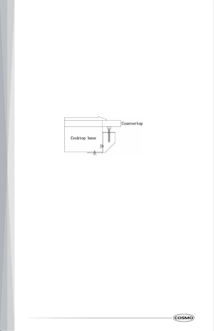
INSTALL COOKTOP
1. Determine whether your cabinet construction provides clearance for
installing hold-down brackets at cooktop base ends.
2. Using two or more people, place cooktop right side up into the cutout.
Note: Make sure that the front edge of the cooktop is parallel to the front
edge of the counter top. If repositioning is needed, lift entire cooktop up
from cutout to avoid scratching the countertop.
3. Attach hold-down brackets to cooktop base bottom with the screws
supplied. Securely tighten screws.
22
Explosion Hazard
Use a new CSA International approved gas supply line and install a shut-
off valve for new installations.
Securely tighten all gas connections.
If connected to LP, have a qualified person make sure gas pressure does
not exceed the maximum pressure listed in the "Gas Supply Requirement"
section.
Examples of a qualified person include:
• licensed heating personnel,
• authorized gas company personnel, and
• authorized service personnel.
Failure to do so can result in death, explosion or fire.
This appliance shall be installed only by authorized persons and in
accordance with the manufacturer's installation instructions, local gas fitting
regulations, municipal building codes, electrical wiring regulations, local
water supply regulations.
This cooktop is factory-set for use with Natural gas. To use this cooktop with
Propane gas, see the "Gas Conversions" section before connecting this
cooktop to the gas supply. Gas conversions from Natural gas to Propane gas
or from Propane gas to Natural gas must be done by a qualified installer.
TYPICAL FLEXIBLE CONNECTION
The following shows a typical connection. Your connection may be different
according to the supply line type, size, and location.
WARNING
GAS CONNECTION
1. Make sure the gas line shut-off valve is close.
2. Apply pipe-joint compound made for use with Natural and LP gas to the
smaller thread ends of the flexible connector adapters.
23
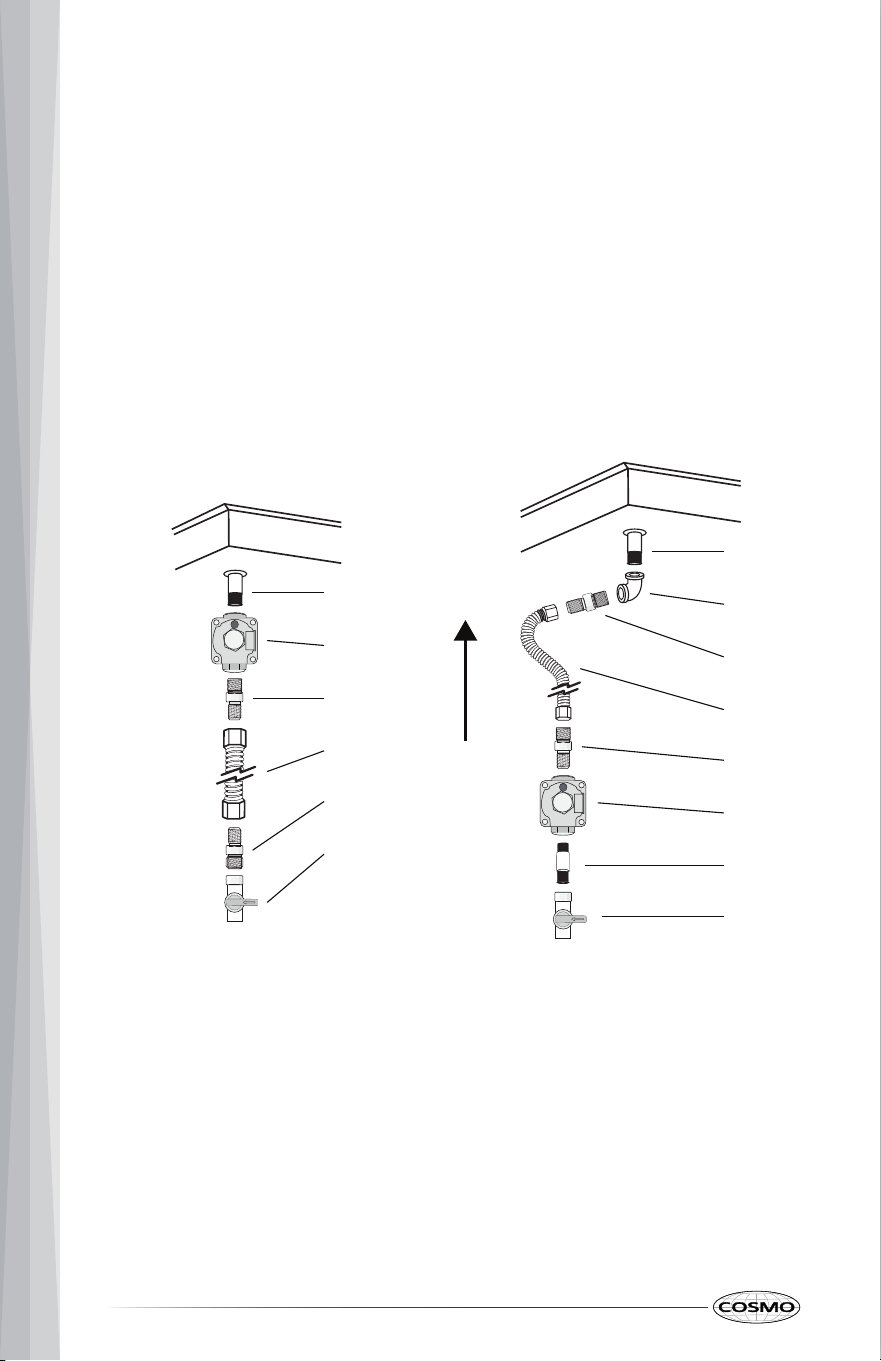
Gas flow into cooktop
No obstructions below cooktop Suggested installation to avoid
interference below cooktop
A
B
C
D
E
F
A
B
C
D
E
F
G
H
A. Manifold entrance
B. Gas pressure regulator
C. Flare union adapter
D. Flexible connector
E. Flare union adapter
F. Manual gas shutoff valve
A. Manifold entrance
B. 3/4" (1.9 cm) elbow
C. Flare union adapter
D. Flexible connector
E. Flare union adapter
F. Gas pressure regulator
G. 1/2" (1.3 cm) or 3/4" (1.9 cm)
gas pipe
H. Manual gas shutoff valve
3. Attach one adapter to the gas pressure regulator and the other adapter
to the gas shutoff valve. Tighten both adapters, being certain not to
move or turn the gas pressure regulator.
Note: Install the gas pressure regulator with the arrow pointing in the
direction toward the bottom of the cooktop base and in a position where
you can reach the regulator access cap.
4. Use a 15/16" (2.4 cm) combination wrench and channel lock pliers to
attach the flexible connector to the adapters. Check that connector is not
kinked.
24
WARNING
Electrical Shock Hazard
Disconnect power before servicing.
Plug into a grounded 3-prong outlet.
Do not use an adapter or an extension cord.
Failure to do so can result in death, fire, or electrical shock
1. Open the manual shutoff valve in the gas supply line. The valve is open
when the handle is parallel to the gas pipe.
2. Test all connections by brushing on an approved noncorrosive leak-
detection solution. If bubbles appear, a leak is indicated. Correct any leak
found.
3. Remove, if any, packaging tapes securing the burners on the surface. If
the cooktop burner bases and caps are not pre-installed, remove them
from package containing parts, align and place the burner bases and
caps accordingly.
CONVERT TO LP GAS (OPTIONAL)
This cooktop is shipped from the factory set up to use natural gas. It can
be converted to use LP gas by a qualified service technician. The LP kit is
not included with this unit, it is sold seperately.
The conversion to LP requires all surface burner orifices to be changed. In
addition, the nozzle on the gas pressure regulator needs to be reversed.
See "GAS CONVERSION" section for detailed instructions.
NOTE: All replaced orifices must be left with the consumer, including the
instructions and retrofit sizes and orifice indication.
COMPLETE CONNECTION
25
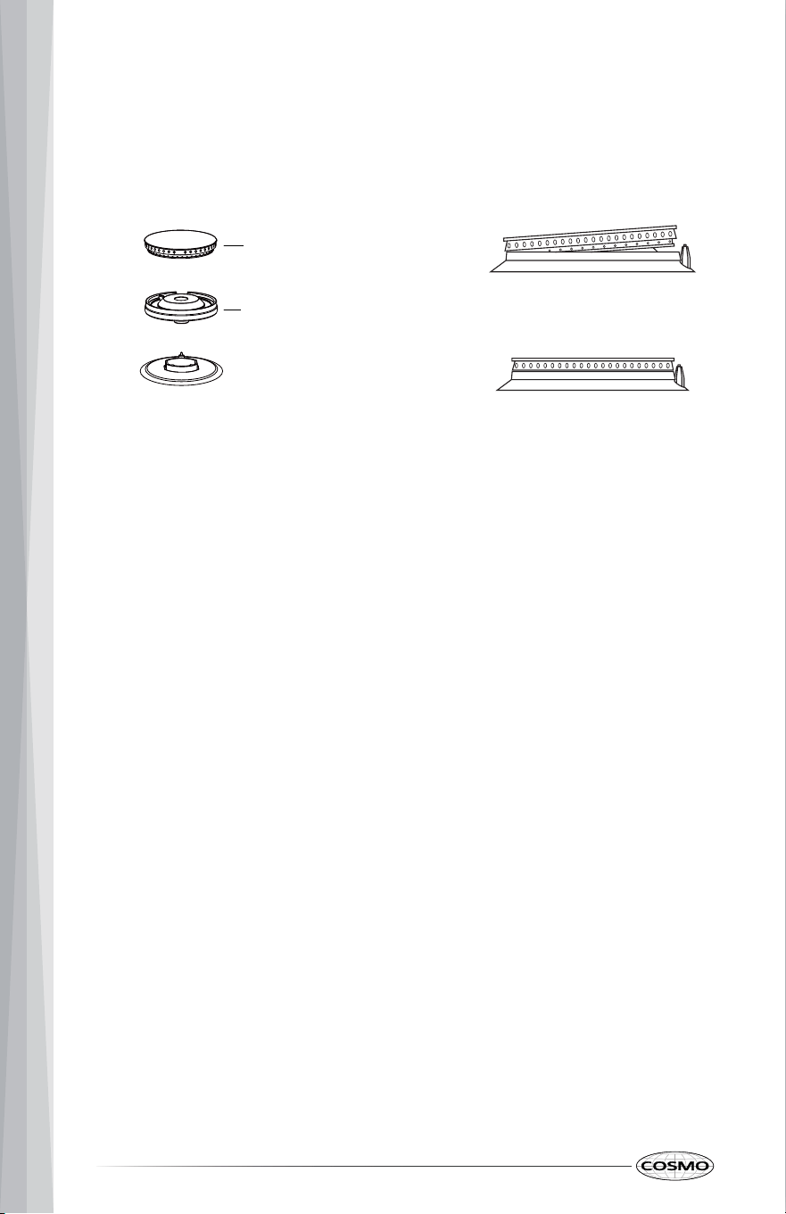
Note: Align notches in burner caps with pins in burner base. Burner caps
should be level when properly positioned. If burner caps are not properly
positioned, surface burners will not light.
4. Place burner grates over burners and caps.
5. Plug in cooktop or reconnect power.
26
Cap
Base
Standard burner
Incorrectly positioned
Correctly p
ositioned
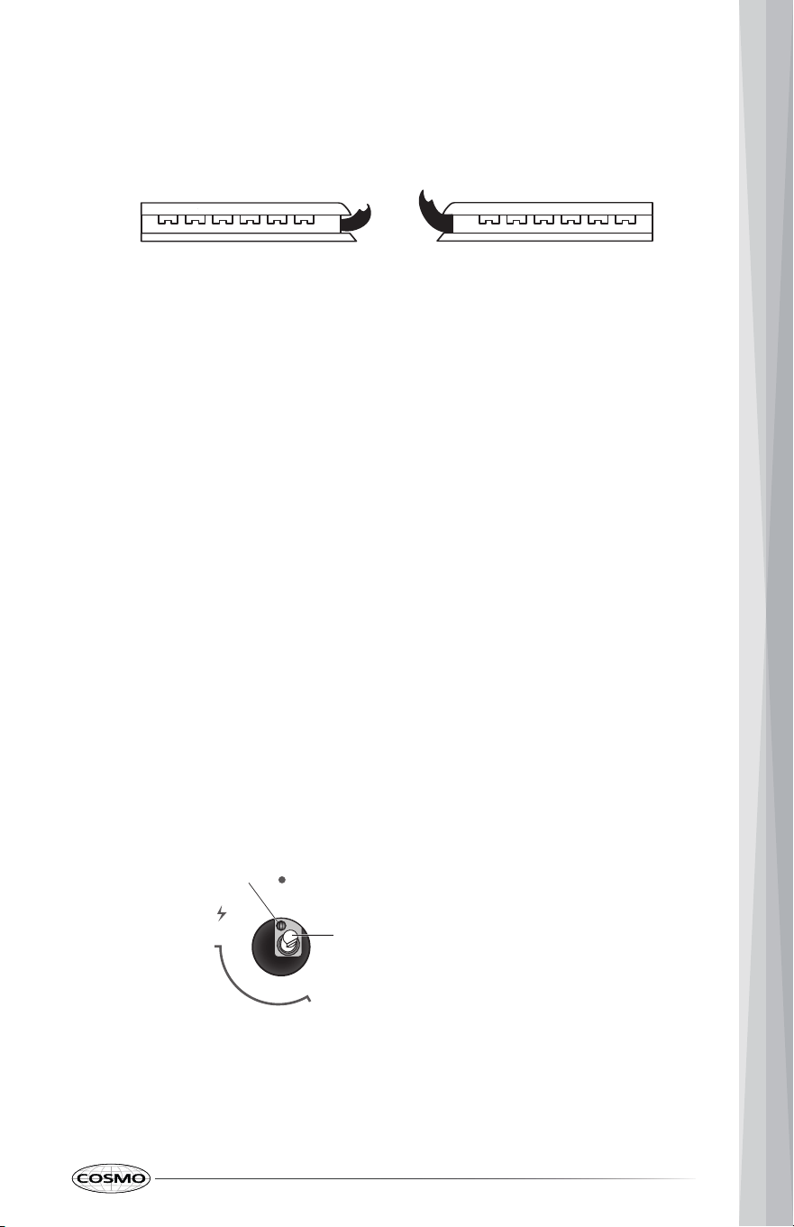
If burners do not light properly:
a
b
ADJUST FLAME HEIGHT
Check and adjust the height of top burner flames. The cooktop "low" burner
flame should be a steady blue flame approximately 1/4" (6 mm) high. Propane
gas flames have a slightly yellow tip.
To adjust standard burner:
IMPORTANT: Adjustments must be made with two other burners in operation
on a medium setting. This prevents the upper row of flames from being set too
low, resulting in the flame being extinguished when other burners are turned
on.
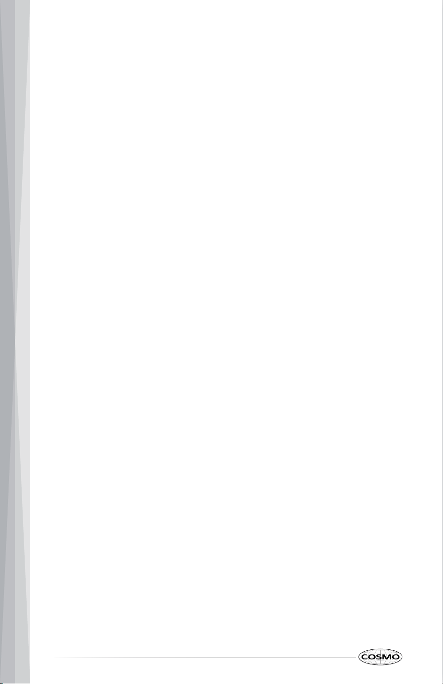
The flame can be adjusted using the adjustment screw in the center of the
valve stem. The valve stem is located directly behind the control knob.
Adjustment screw
Control k
nob s
tem
1. Turn burner control knob to the "OFF" position.
2. Check that the cooktop is plugged in. Check that the circuit breaker has
not tripped or the household fuse has not blown.
3. Check that the gas shutoff valves are set to the "open" position.
4. Check that burner caps are properly positioned on burner bases.
1. Light the burner and turn the knob to the lowest setting (MIN).
2. Pull and remove the control knob.
3. Insert a small, flat-blade screwdriver into the adjustment screw, and
slowly turn the screw until the flame appearance is correct.
• Open the valve more if the flames are too small or fluttered.
• Close the valve more if the flames are too large.
4. Replace the control knob.
5. Test
and check the flame by turning the control knob from the lowest to
the highest settings.
27
ig lameLow lame
MAX
MIN
OFF
a
b
NOTE: For burners (on some models) with safety valve, make sure that the
regulation obtained is sufficient to maintain heating of the thermocouple. If it
is not, increase the minimum flame.
ABNORMAL OPERATION
ANY OF THE FOLLOWING ARE CONSIDERED TO BE ABNORMAL OPERATION
AND MAY REQUIRE SERVICING:
• Yellow tipping of the hob burner flame
• Sooting up of cooking utensils.
• Burners not igniting properly.
• Burners failing to remain lit.
• Burners extinguished by oven door.
• Gas valves, which are difficult to turn.
IN CASE THE APPLIANCE FAILS TO OPERATE CORRECTLY, CONTACT THE
AUTHORIZED SERVICE PROVIDE IN YOUR AREA.
THE BURNERS REQUIRE NO REGULATION OF THE PRIMARY AIR.
28
GAS CONVERSION
WARNING
Explosion Hazard
Use a new CSA International approved gas supply line.
Install a shut-off valve.
Securely tighten all gas connections.
If connected to LP, have a qualified person make sure gas pressure does
not exceed the maximum pressure listed in the "Gas Supply Requirement"
section.
Examples of a qualified person include:
• licensed heating personnel,
• authorized gas company personnel, and
• authorized service personnel.
Failure to do so can result in death, explosion or fire.
LP/PROPANE GAS CONVERSION
IMPORTANT: Gas conversions must be done by a qualified service technician
in accordance with the manufacturer's instructions and all codes and
requirements of the authority having jurisdiction. The qualified agency
performing this work assumes the gas conversion responsibility.
Convert Gas Pressure Regulator
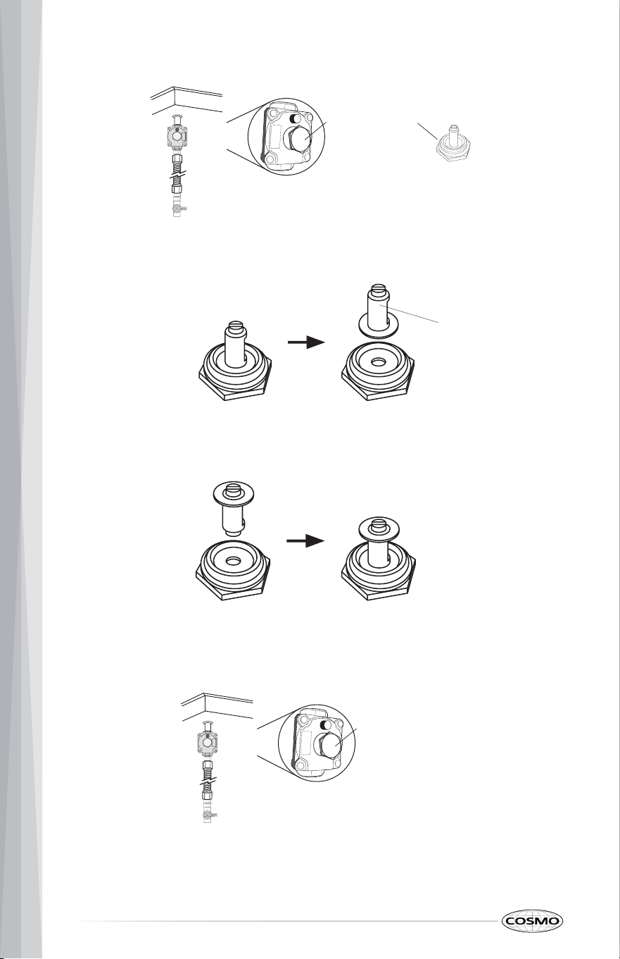
1. Turn manual shutoff valve to the closed position.
2. Unplug cooktop or disconnect power.
3. Locate the gas pressure regulator below the cooktop.
IMPORTANT: Do not remove the gas pressure regulator.
29
Natural gas
position
Propane gas
position
Retainer pin
Regulator cap
4. Unscrew the regulator cap with the wrench.
5. Remove the retainer pin that is currently positioned for use with natural
gas.
6. Turn the retainer pin upside down and place it back into the regular cap.
The regular cap is now positioned for use with LP gas.
7. Screw and tighten the regulator cap back into the gas pressure regulator
with the wrench.
30
Regulator cap
07
5
Convert Surface Burners
Orifice size
(075 - Denotes 0.75 mm)
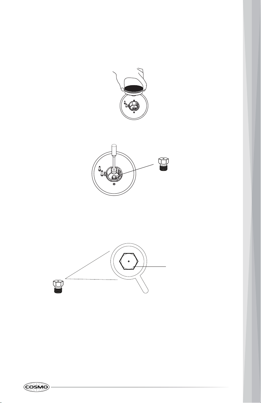
1. If installed, remove the burner grates.
2. Remove the burner grates, burner caps, and the burner base.
3. Remove the natural gas orifices with a 9/32" (7 mm) nut driver.
4. Replace the natural gas orifices with the correct LP gas orifices from the
LP conversion kits. LP gas orifices are stamped with a size. Refer to the
following chart for correct LP gas orifice ratings and sizes for proper
placement.
31
Orifice
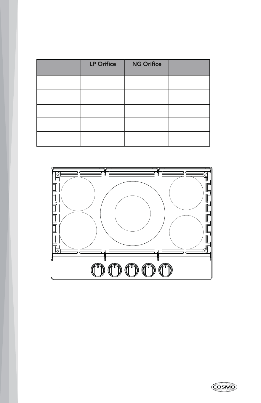
Orifice Chart for Surface Burners:
COS-CTGH305SS and COS-CTGH365SS
Placement
Burner
Size (mm) Size (mm) Rating
Front Left 1.03 1.57 12,000 BTU
Front Right 0.95 1.43 10,000 BTU
Rear Left 0.91 1.36 9,000 BTU
Rear Right 0.75 1.09 6,000 BTU
Center
Inner: 0.56 Inner: 0.78
Outer: 1.19 Outer: 2.09
22,000 BTU
9K BTU
Outer
6K BTU
LP: 0.91
LP: 1.
19
LP: 0.75
NG: 1.36
NG: 1.09
Inner
LP: 0.56
NG: 0.78
12K BTU
10
K BTU
LP: 1.03
LP: 0.95
NG: 1.57
Outer
NG: 2.09
NG: 1.43
LP and NG Orifices are in size (mm)
Total: 22K BTU
32
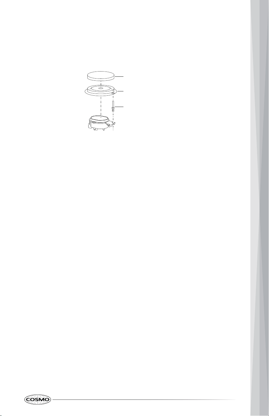
5. Keep and store natural gas orifices in case of re-installation with natural
gas.
6. Replace the burner base, the burner caps, and the burner grates.
Complete Gas Conversion
1. Open shutoff valve in the gas supply line.
2. Plug in cooktop or reconnect power.
• Refer to "Gas Connection" section in the "Installation Instructions" section
for proper connection of the cooktop to the gas supply.
• Refer to "Complete Connection" section to complete this procedure.
• Refer to the "Adjust Flame Height" section for burner flame adjustments.
IMPORTANT: You may have to adjust the low setting for each cooktop
burner.
Burner cap
Burner base
Igniter
33
a
b
c
a
b
c
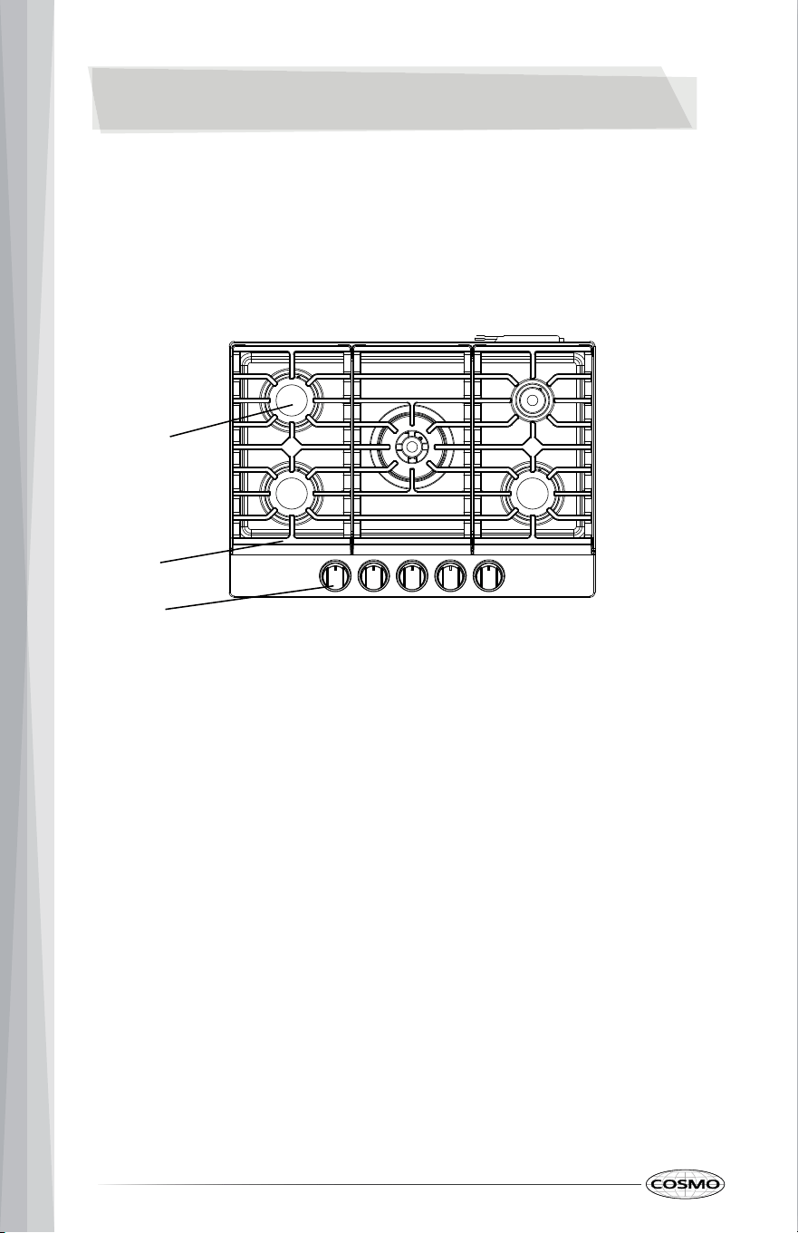
Surface burner
Grate
Burner control knob
OVERVIEW
COOKTOP LAYOUT
This illustration covers several different models. The cooktop you have
purchased may have some or all of the items listed. The locations and
appearances of the features shown here may not match those of your model.
34
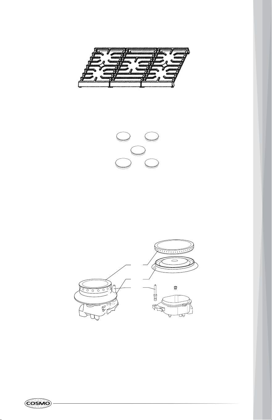
Surface burners and caps (5)
Model: COS-CTGH305SS and COS-CTGH365SS
Surface burner grates (3)
Model: COS-CTGH305SS and COS-CTGH365SS
WHAT'S INCLUDED
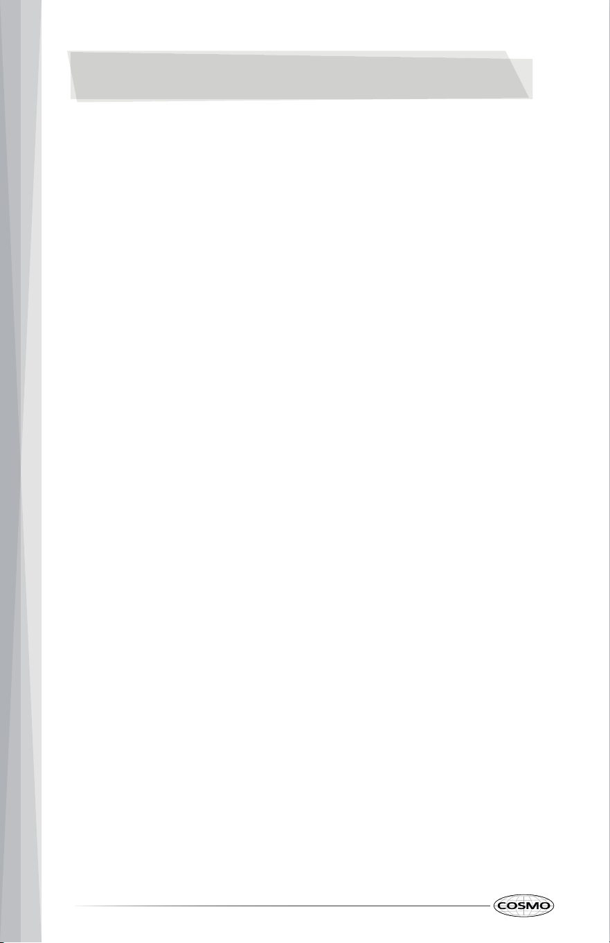
BURNER LAYOUT
35
a
b
c
Burner cap
Burner head
c
Electrode
a
b
COOKTOP USE
Read the instructions before installing or using this appliance.
• This appliance shall be installed in accordance with the regulations in
force and only used in a well-ventilated space.
• The use of a gas-cooking appliance results in the production of heat and
moisture in the room in which it is installed. Ensure that the kitchen is well
ventilated: keep natural ventilation holes open or install a mechanical
ventilation device (mechanical extractor hood).
• Prolonged intensive use of the appliance may call for additional
ventilation, for example opening of a window, or more effective
ventilation, for example increasing the level of mechanical ventilation
where present.
• Burners should be operated only when covered by cookware. Burner
flames not covered by cookware present a risk of fire or clothing ignition.
• Never let flames extend beyond the sides of the cookware. Failure to
comply may result in serious injury.
• Always turn off the surface burners before removing cookware. All
surface burners should be turned off when you are not cooking.
• When removing hot cookware from the burner, be sure to lift it high
enough to not come in contact with the control knobs. Hot cookware
coming into contact with the control knobs could cause damage, such as
melting or warping.
• If you smell gas, turn off the gas to the cooktop and call a qualified
service technician. NEVER use an open flame to locate a leak.
• Do not operate the burner for an extended period of time without
cookware on the grate. The finish on the grate may discolor or chip
without cookware to absorb the heat.
• Do not attempt to disassemble any burner while another burner is on.
Damage to the product may occur.
• Be sure the burners and grates are cool before you place your hand, a
pot holder, or cleaning materials on them.
36
USING THE COOKTOP BURNERS
IMPORTANT: Make sure all cooktop burners are properly installed.
1. To ignite a burner, push down on the burner control knob and turn it
counter-clockwise towards the "HI" position. The clicking sounds indicate
the system is igniting.
2. After the cooktop burner lights, release and turn the control knob
between HI, Med, and Low to adjust the flame level.
3. To turn off the burner, turn the control knob to the OFF position.
POWER FAILURE
In case of prolonged power failure, the surface burners can be lit manually
with a match. Using extreme caution, hold a lit match near the ports beneath
the surface burner cap, then push down on the burner control knob and
slowly turn it counter-clockwise towards the "Hi" position. Once lit, release and
turn the control knob to adjust the flame level, and surface burner will
continue to operate normally.
NOTES:
The electric igniter must not be actuated for longer than 15 seconds. Should
the burner not light, or should the burner be unintentionally turned off,
immediately close the burner, and wait at least 1 minute before repeating.
Once ignited, adjust the flame as desired.
For lower gas consumption and a better result, use saucepans with a diameter
matching the diameter of the burner, to avoid the flame coming up around
the sides of the saucepan. See the Container Table. Use only flat-bottomed
pans.
As soon as liquid starts to boil, turn the flame down to a level sufficient to
maintain boiling.
37
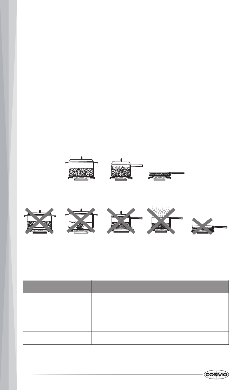
CONTAINER TABLE
COOKWARE
MATCH PAN DIAMETER TO FLAME SIZE
The flame should be the same size as the bottom of the pan or smaller. Do not
use small pans with high flame settings as the flames can lick up the sides of
the pan. Oversize pans that span two burners are placed front to rear, not
side to side.
USE BALANCED PANS
Pans must sit level on the cooktop grate without rocking. Center the pan over
the burner.
USE A LID THAT FITS PROPERLY
A well-fitting lid helps shorten the cooking time. Flat, heavy bottom pans
provide even heat and stability.
Burner Min Saucepan Max Saucepan
Front Left /Rear Left
3.5" (9.0 cm) 6.3" (16 cm)
Front Right 5.1" (13 cm) 7.1" (18 cm)
Rear Right 5.9" (15 cm) 10.2" (26 cm)
Center 8.3" (21 cm) 10.2" (26 cm)
38
BALANCED PAN
UNBALANCED
PAN
CONVEX
(ROUNDED)
CONCAVE
(HOLLOW)
FLAME TOO LARGE
FOR PAN SIZE
USE LIDS THAT
FIT PROPERLY
COOKTOP CARE
CLEANING
IMPORTANT: Before cleaning, make sure all controls are off and the cooktop
is cool. Always follow label instructions on cleaning products. Soap, water,
and a soft cloth or sponge are suggested first, unless otherwise noted. Do not
use abrasive cleaning products.
CONTROL KNOBS
• To remove the knobs, be sure the knobs are in the OFF position.
• Pull knobs straight away from control panel to remove.
Cleaning Recommendation:
• The knobs should be cleaned with soap and water.
• Do not clean knobs in the dishwasher or use abrasive cleaners or steel
wool.
• Do not remove the seals under the knobs.
BURNER GRATES
• To avoid chipping, do not bang grates against each other or hard
surfaces, such as cast iron cookware. Although the grates are durable,
they will gradually lose their shine due to exposure to high temperatures.
Cleaning Recommendation:
• Soap and Water: Use a nonabrasive plastic scrubbing pad and mildly
abrasive cleanser, soap, and water.
• Dishwasher: The grates may be cleaned in the dishwasher. Remove any
burnt-on food prior to placing the grates in the lowest rack in the
dishwasher.
BURNER CAPS
• Do not place caps in the dishwasher or reassemble caps on burners when
wet.
Cleaning Recommendation:
• Use a nonabrasive plastic scrubbing pad and mildly abrasive cleanser,
soap, and water.
39
BURNER BASE
• The holes in the burner bases must be kept clean for proper ignition and
a complete, even flame. Spillovers should be cleaned immediately since
they can clog the openings in the burners.
IMPORTANT: Before cleaning, make sure all controls are OFF and the
cooktop is cool.
Cleaning Recommendation:
• Remove the burner cap from the base. Clean the burner cap with hot
soapy water, and then rinse it.
• Remove the burner base and clean the gas tube opening under the base.
• Clean clogged burner ports with a straight pin, needle, or small-gauge
wire as shown. Do not use a wooden toothpick or clean in the dishwasher.
• Gently clean the igniter with a damp cloth.
STAINLESS STEEL COOKTOP SURFACE
• Food spills containing acids, such as vinegar and tomato, should be
cleaned as soon the cooktop is cool. These spills may affect the finish.
• Do not use scouring pads, abrasive cleaners, cooktop cleaner, steel wool
pads, gritty washcloths, or abrasive paper towels.
Cleaning Recommendation:
• For best results, use a soft cloth or non-scratch sponge.
• Rub in direction of the grain to avoid damaging the surface.
• Use stainless steel or all-purpose cleaner.
PORCELAIN ENAMEL COOKTOP SURFACE (ON SOME MODELS)
Cleaning Recommendation:
• Use a nonabrasive scrubbing pad and glass cleanser or a mild liquid
cleaner.
40
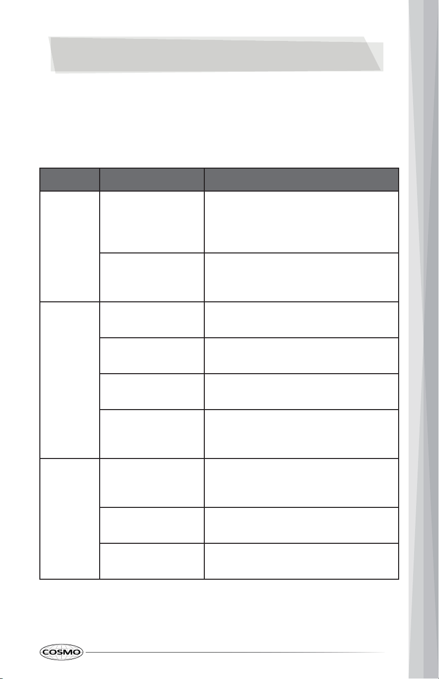
TROUBLESHOOTING
First try the solutions suggested here to possibly avoid the cost of a service
call.
COOKTOP PROBLEMS
PROBLEM POSSIBLE CAUSE SOLUTION
Burner
will not
ignite
There is no power to
the cooktop.
Make sure electrical plug is plugged
into a live, properly grounded outlet.
Replace the fuse or reset the circuit
breaker.
Burner parts or
igniters may be wet,
dirty, or misaligned.
Check that the burner parts and igniter
are clean, dry, and correctly assembled.
Burner
will not
operate
Gas shut-off valve is
close.
Open the gas shut-off valve.
First time use. Air
still in the gas line.
Turn on any one of the surface burner
knobs to release air from the gas lines.
Control knob is not
set correctly.
Push in knob before turning to a
setting.
The burner port is
clogged.
Clean burner port opening using a stiff,
nylon toothbrush or a straightened
paper clip.
Burner
Flames
are
uneven,
yellow
and/ or
noisy
Burner port(s) are
clogged.
Clean burner port opening using a stiff,
nylon toothbrush or a straightened
paper clip.
Burner caps are not
positioned properly.
Place burner caps so that the alignment
pins are properly aligned with the slots.
Propane gas is
being used.
The cooktop should be converted to LP
gas by a qualified technician.
41
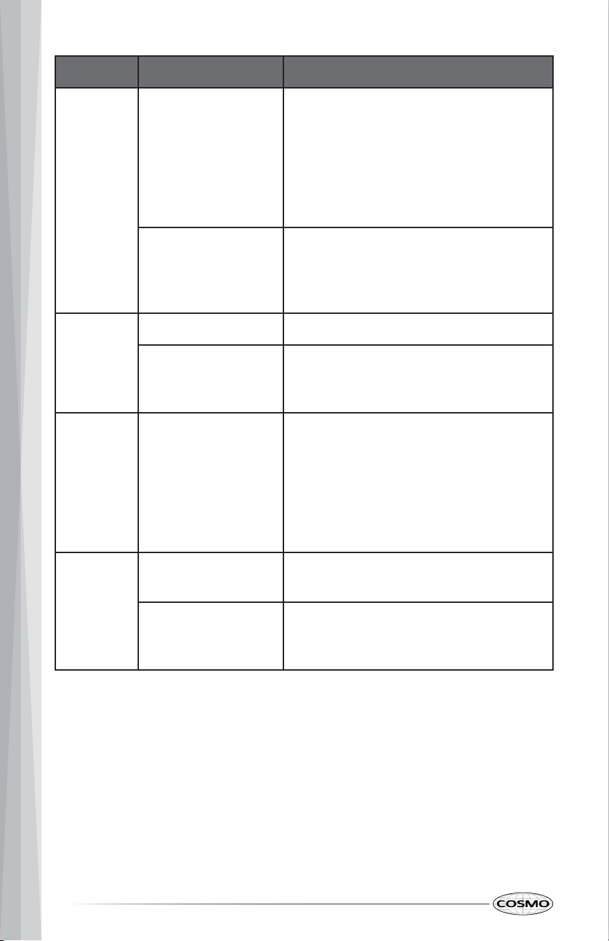
PROBLEM POSSIBLE CAUSE SOLUTION
Burner
flame is
too high
or too low
Cooktop gas supply
is not correct.
Ensure the cooktop is set for the correct
gas type. It is factory set for natural
gas. If connecting to LP gas, the burners
should be converted to LP gas with the
orifice kit supplied and the pressure
regulator converted to the LP gas
setting by a qualified technician.
The gas pressure is
not correct.
Make sure the pressure regulator is
installed correctly and the gas line
pressure is correct. See Installation
Instructions.
Burner
makes
popping
noises
The burner is wet. Allow the burner to dry before using.
The burner cap or
gas spreader is not
positioned correctly.
Place burner caps so that the alignment
pins are properly aligned with the slots.
Excessive
heat
around
cookware
on
cooktop
The cookware is not
the proper size for
the burner.
Use cookware with a bottom surface
approximately the same size as the
cooking area and burner. Cookware
should not extend more than 1" (2.5 cm)
outside the cooking area. Adjust the
flame so that it does not come up
around the cookware.
Cooking
results
are not
what
expected
Using incorrect
cookware.
See the "Cookware" section.
The control knob is
not set to the
proper heat level.
See the "Adjust Flame Height" section.
42
LIMITED WARRANTY
WARRANTY AND SERVICE
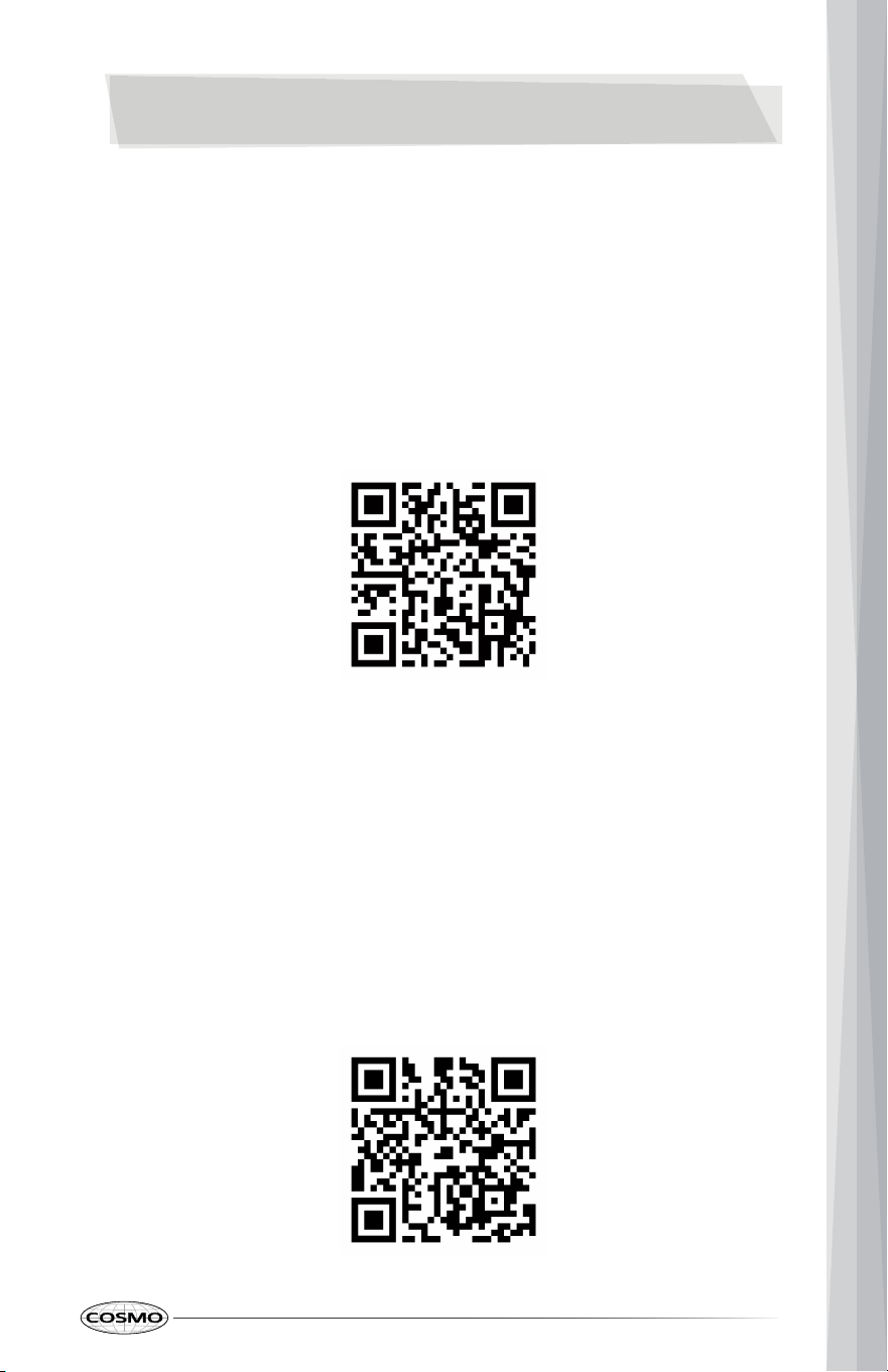
TO RECEIVE WARRANTY SERVICE, YOUR PRODUCT MUST BE REGISTERED.
TO REGISTER AND REVIEW FULL WARRANTY DETAILS, VISIT:
WWW.COSMOAPPLIANCES.COM/WARRANTY
SCAN TO REGISTER
CUSTOMER SUPPORT
TO CHAT WITH US LIVE FOR ASSISTANCE, VISIT:
WWW.COSMOAPPLIANCES.COM/CHAT
SCAN TO CHAT
43
IMPORTANT
Do Not Return This Product To The Store
If you have a problem with this product, please contact COSMO Customer
Support at
+1 (888) 784-3108
DATED PROOF OF PURCHASE, MODEL #, AND SERIAL # REQUIRED FOR
WARRANTY SERVICE.
IMPORTANT
Ne pas Réexpédier ce Produit au Magasin
Pour tout problème concernant ce produit, veuillez contacter le service des
consommateurs Cosmo Customer Support au
+1 (888) 784-3108
UNE PREUVE D’ACHAT DATEE EST REQUISE POUR BENEFICIER DE LA GARANTIE.
IMPORTANTE
No regrese este producto a la tienda
Si tiene algún problema con este producto, por favor contacte el ayuda al
cliente COSMO al
+1 (888) 784-3108
(Válido solo en E.U.A.)
NECESITA UNA PRUEBA DE DE COMPRA FECHADA, NÚMERO DE MODELO Y DE
SERIE PARA EL SERVICIO DE LA GARANTÍA.
Correct Disposal of this product:
This marking indicates that this appliance should not
be disposed with other household wastes. To prevent
possible harm to the environment or human health
from uncontrolled waste disposal, recycle it responsibly
to promote the sustainable reuse of material resources.
44

MEMO
45
MEMO
46

MEMO
47

Cosmo is constantly making efforts to improve the quality and
performance of our products, so we may make changes to our
appliances without updating this manual.
Electronic version of this manual is available at:
www.cosmoappliances.com
APPLIANCES