Instruction manual
US
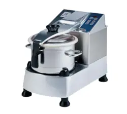
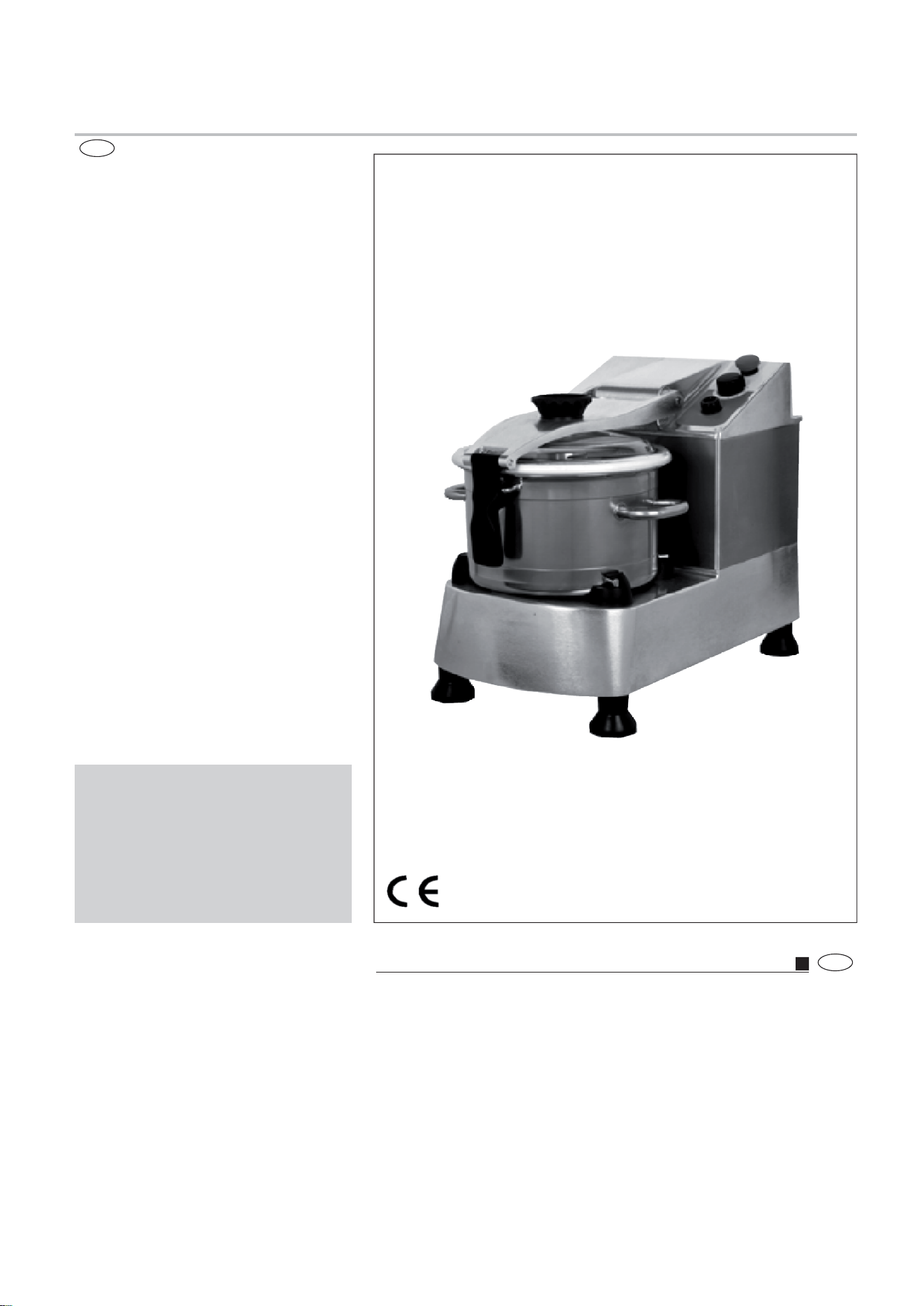
Food processor
N°29474 A
US
K120/KE120
K180
05/2007
K120/180 US 01 07
1.1
2.1
K120/180 01-01/2007K120/180 03-2/99
K120/180 05-01/2007
K120/180 07-01/2007
K120/180 08-1/99
K120/180 09-01/2007
K120/180 16-1/99
K120/180 10-01/2007
K120/180 04-01/2007
K120/180 02-01/2007
2.3
3.2c
3.2a
3.2
3.3b 3.3c
K120/180 11-01/2007
3.3d
K120/180 12-01/2007
3.3e
K120/180 13-01/2007
3.3f
3.3
6.1
3.3a
3.3
K120/180 06-01/2007
3.2b
123
A
B
ABC(V) D(Hz) E(tr/mn) F(kW)
1500/3000
300/3000
1500/3000
380-415
380-415
380-480
200-240
380-480
50
50/60
50
60
60
22828
22904
22829
1,5/2,2
2,2
3/3,6
3,7/5,5
3,5/4,9
15
6,9/9,3
6,7/8,4
H(A)G(A) I(kW/h)
16
20
20
2/3
3
4/5
3
3
1
3.1
K180
D
B
E
G
F
A
E
A
G
D
B
F
C
305
504/594
515
680
305
416
1181/1267
725
GB
2.1
1.1
2.1
Contents
Introduction 1
Installation 1
Use, safety 3
Cleaning and hygiene 5
Fault fi nding 6
Maintenance 7
Conformity with regulation 8
Introduction
1.1 DESCRIPTION
• These 11.5 and 17.5 litre capacity cutters are machines
designed for cookery professionals for mincing, mixing, emulsi-
fying, liquidising, kneading, etc. and can be used to process all
types of foodstuffs (meat, vegetables, fruits, condiments, pastry,
mayonnaise, etc.).
• For special preparations other than foodstuffs, PLEASE ASK
US FOR DETAILS.
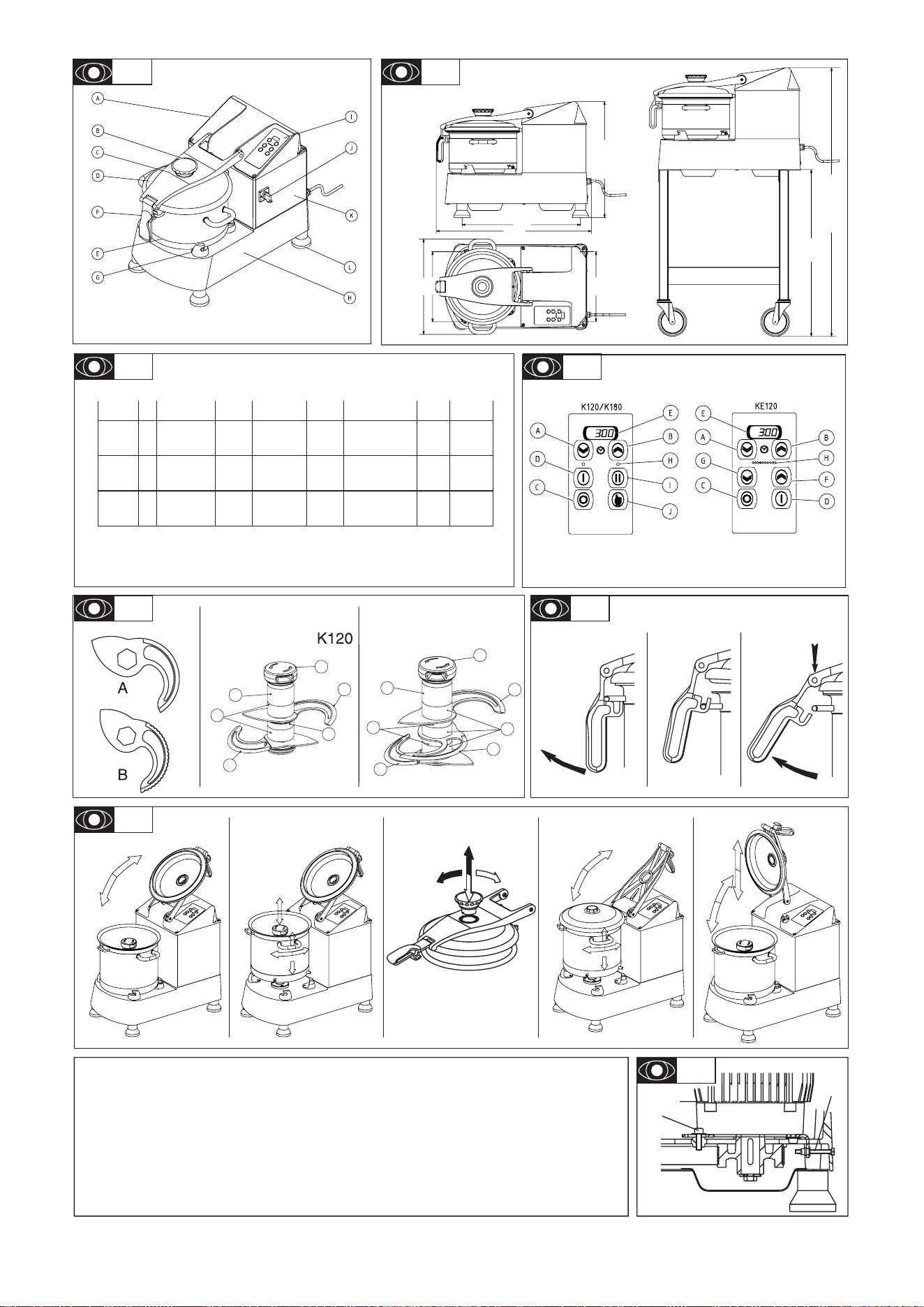
A Motor cover
B Removable funnel
C Removable lid arm assembly
D Transparent polycarbonate lid
E Stainless steel bowl
F Bowl locking knob
G Bowl locking clamps
Installation
2.1 DIMENSIONS - WEIGHT (FOR INFORMATION ONLY)
- Dimensions of packaging: (L x l x h) mm:
. 11,5l -17,5 modelx : 770 x 530 x 780 mm
. Optional table: 750 x 600 x 200
- Overall dimensions (mm):
2.2 LOCATION
• These machines are designed to be fi tted onto a work top
(table, base, etc.) of between 400 and 900 mm in height. The
four feet ensure that it remains perfectly stable.
• A stainless steel mobile table is available in option for the
cutters.
This document is to be used in conjunction with the original manufacturer’s manual.
The symbols correspond with the numbered drawings of the original manual.
05/2007
H Body
I Fascia
J Mains power switch
(17.5l model only)
K Stainless steel housing
L Rubber feet
Introduction
The User Manual contains useful information for the user on
how to work correctly and in complete safety, and is designed
to make it easier to use the machine (called «machine» or
«appliance» below).
What follows is in no case intended to be a long list of warnings
and constraints, but rather a series of instructions meant to
improve the service provided by the machine in every respect,
and particularly to avoid a series of injuries or damage to equi-
pment that might result from inappropriate procedures for use
and management.
It is essential that all the people responsible for transporting,
installing, commissioning, using, maintaining, repairing or dismant-
ling the machine should consult this manual and read it carefully
before proceeding with the various operations, in order to avoid
any incorrect or inappropriate handling that might be result in
damage to the machine or put people’s safety at risk.
It is just as important that the Manual should always be available
to the operator and it should be kept carefully where the machine
is used ready for easy and immediate consultation in case of any
doubt, or in any case, whenever the need arises.
If after reading the Manual, there are still any doubts concerning
how to use the machine, please do not hesitate to contact the
Manufacturer or approved After Sales Service provider, who
is constantly available to ensure quick and careful service for
improved machine operation and optimum effi ciency.
Note that the safety, hygiene and environmental protection stan-
dards currently applicable in the country where the machine is
installed must always be applied during all phases of machine
operation. Consequently it is the user’s responsibility to ensure
that the machine is operated and used solely under the optimum
safety conditions laid down for people, animals and property.
- Gross weight when packaged : 11,5/17,5: 83/92 kg
- Net weight: 11,5/17,5: 58/68 kg
1 K120/180 GB 01 07
K120/180 GB 01 07 2
Connection to the electrical power supply must be done according to proper professional practice by a qualifi ed and authorised
person (see current standards and legislation in the country of installation).
If an adapter is used on the socket, a check must be made that the electrical characteristics of this adapter are not lower than
those of the machine.
Do not use multiple plugs
The AC power supply to the machine must comply with the following conditions;
- Maximum voltage variation: ±5%
- Maximum frequency variation: ±1% on a continuous basis, ± 2% over short periods
ATTENTION: the electrical installation must comply (for design, creation and maintenance) with the legal and standard
requirements in the country where used.
- Before connecting the machine to the electrical power supply, check that the voltage of the electrical system is the same as
that marked on the rating plate and the label on the power cable.
- The machine’s electrical power supply must be protected against voltage surges (short-circuits and excess voltages) by
using fuses or thermal relays of the appropriate gauge relative to the place of installation and machine specifi cations - see the
specifi cations shown in column G of fi gure 2.3a
ATTENTION: Concerning protection against indirect contact (depending on the type of power supply provided and
connection of the exposed conductive parts to the equipotential protection circuit), refer to point 6.3.3 of EN 60204-1 (IEC
60204-1) with the use of protection devices for automatic shut-off of power in the event of an insulation fault with a TN or
TT system, or, for the IT system, with the use of a permanent insulation or differentials controller for automatic shut-off.
The requirements of IEC 60364-4-41, 413.1 must apply for this protection.
For example: in a TT system, a differential circuit breaker must be installed upline of the power supply, with a suitable
power cut-off (e.g.: 30 mA) on the earthing installation for the place where it is planned to install the machine.
ATTENTION: Failure to comply with these instructions means the customer runs the risk of machine failure and/or acci-
dents due to direct or indirect contacts.
ATTENTION !!
2.3 ELECTRICAL CONNECTION
2.3a
• The 11,5 and 17,5 litre cutters are only available as standard in
three phase, single voltage versions, with two speeds. The 11,5
litre model is also available in single phase supply with speed
variation.
• Check that the voltage of the electrical system is the same as that
marked on the rating plate and the label on the power cable.
• The machine must be protected by a differential circuit breaker
and a fuse of the rating listed in column H of the characteristics
table.
• Motor characteristics:
A Motor code
B Number of phases (3 three phase)
C Nominal voltage in volts (value, range or commutation)
D Frequency (Hertz)
E Motor speed (rpm)
F Nominal power (Watts)
G Nominal current (Amperes)
H Rating of fuse for protecting the electrical line (Amperes)
I Indicative electrical consumption (kWh)
a) Three phase, single voltage 2 speed motor
- Check the direction in which the rotor is turning through the
transparent lid (anti-clockwise - as per the arrow marked
on the rotor handle).
- If it is turning in the wrong direction, change over the two phase
wires of the plug.
b) Three phase, single voltage one speed motor with fre-
quency variator
• The cutter is supplied with a single phase current up to its
variator, which transforms the current to supply the three phase
motor.
• A 2 pin + earth standardised wall socket with a 20 A fuse is
required, that is easily accessible.
• Check that the mains voltage matches that on the rating plate
of the machine and the power supply cable.
• A 3 pin + earth standardised wall socket with a 20 A fuse is
required, as well as a matching watertight plug for the power
cable.
• Check the direction of rotation of the rotor at both speeds:
- Turn the mains power switch (depending on model) in a cloc-
kwise direction to the I position.
- Turn the knob G to the I low speed position (see § 3.1).
The machine must be earthed with the green and yellow
wire.
Note: The machine can only be used on TN (earthing to neutral)
and TT (earthed neutral) type supplies. Where a machine has to
be installed on an IT (impeding or isolated neutral) supply, there
is a solution which consists of inserting an isolating transformer
and locally putting on the machine on TN or TT supply.
The machine must be earthed with the green and yellow
No earth plug = no protection = risk of breakdown.
• Warning to the installer:
This cutter with electronic speed variation is equipped with a fi lter
built into the variator which earths any system interference without
passing through the variator. In order to be effective, the installation
must have a good quality earth, otherwise the interference could
pass through the variator and damage it.
Damage caused by inadequate earthing is not covered by
the guarantee.
Note: The earth values are defi ned according to the residual
differential current (see NFC 15100 standard and PROMONTELEC
guide) and must be checked by an electrician.
In certain circumstances depending on the sensitivity of the
protective cut-outs, it may be necessary to install SI-type
(super immunity) devices to prevent untimely triggering.
To PAT test the Electrolux Range of Food Preparation Equipment,
the PCB board needs to be disconnected before any test is done.
This is due to the fact that the boards are fi tted with a grounding
diode that can give incorrect result during such a test. Also on a
standard appliance a fl ash test of 25 amps and up to 3000v is
used but, as you would expect, to use this on equipment, which
has a printed circuit, board would be quite destructive to that
board. We would recommend the use of a PAT tester approved
for computer systems which use a lower rate of amps.
The appliance is perfectly safe and is CE certifi cated. There are
two ways to get overcome this problem.
· Disconnect the board as instructed and test using test for
PC’s,
· Or install the mixer on a fused spur (no plug) as this takes it
away from being a portable appliance and the PAT test is then
not needed.
Use, safety
Clean the machine properly prior to its fi rst use
This machine is for professional use and must be used by staff trained to use, clean and maintain it, in terms or reliability and
safety.
Use the machine in adequately lit premises (See applicable technical standard for the country of use. In Europe, refer to standard
EN 12464-1)
When handling the machine, always check that the parts taken hold of are not mobile elements: risk of dropping and injury to
the lower limbs.
Uncontrolled closure of the lid or ram press involves a risk of crushing the fi ngers.
Never put a hand in the ejection area while the machine is in operation; risk of injury. It is strictly forbidden to put the safety
systems out of action or modify them: Risk of permanent injury!!!!
Check that the safety devices operate correctly each time before using (see paragraph on «safety system adjustments»).
Never put a hand, a hard or frozen object in the appliance
For health and safety reasons, always use a washable or disposable strong head covering that covers the hair completely.
ATTENTION: All operations, whether using, cleaning or maintenance, present risks of cuts; never force and always keep
hands a reasonable distance from cutting edges.
Always use appropriate protective equipment when carrying out these operations.
The machine is not designed for use in explosive atmospheres.
ATTENTION !!
3.1
3.1 USER SAFETY IS ENSURED BY:
- User safety is ensured by the following features:
- The motor stops when the lid is unlocked
- The bowl and lid must be locked before the appliance can
start
- After a stop, the «start» button must be operated («no voltage»
feature)
- The motor is halted by a brake before the rotor can be ac-
cessed
- Continuous action operation to control the progress of the
preparation.
- Automatic locking in place of the rotor during rotation, linked
to the blade angle
- The standardised size of the lid spout allows products to be
added in mid-cycle.
- The design of the bowl (leak prevention tube).
- The bowl, lid and rotor are easy to dismantle for cleaning.
- CONTROL PANEL
A,B,E: timer
C : stop button
D : start button
F : increased speed button
G: lower speed button
H : speed indication lamp
I : high speed position II
J : pulse operation button
F-G : variable speed model
- The cutters can be started if:
- the lid is correctly locked onto its 4 clamps
- the lid has been lowered and locked.
- the mains power switch (K 180 model) is in the start position
a) Continuous operation: I –II
- Select ------ on E by pressing and holding button A.
- Start by pressing button D or button I.
- Stop by pressing button C.
b) Pulse operation:
- Press button J
c) Change speed:
- Select speed H by pressing F or G
d) Stop:
- Press button C.
Preferably use button C then unlock the lid.
- If the machine is stopped for several days, unplug it to switch
off the power supply to the variator
RESIDUAL RISKS
The machine presents the following residual risks;
• The upper cover of the machine may result in the fi ngers being
crushed if it is closed without being controlled properly.
Always start in low speed then change to a higher speed
once the texture of the product changes.
3 K120/180 GB 01 07
3.2a
3.2b-c
3.2a
3.2 VARIOUS EQUIPMENT:
• As standard, the cutters have a rotor with two very hard,
angled plain stainless steel blades (A), which may be used for
the following types of work:
- Mincing of meats and chopping of parsley, garlic, onions,
etc.
- Preparation of butters, mayonnaise, purées, etc.
- Kneading of all types of doughs/pastries.
• A rotor with toothed blades (B) is available for liquidising shel-
lfi sh and fi sh and grinding breadcrumbs, almonds, etc. (please
ask for details)
• Rotors without cut-outs are available on request, for certain
tasks using meat. (speed 1500rpm).
A Lower inclined perforated knife
B Upper inclined perforated knife
C Middle fl at perforated knife
D Handle
E 15 mm spacer
F 30 mm spacer
G Spacer with shoulder
3.3a
3.3b
3.3c
3.3 USE OF THE CUTTERS
• The cutters are supplied with the bowl and the lid fi tted and
the rotor inside.
Before using the cutters, always check the cleanliness of the
bowl, the lid, the rotor and the drive shaft.
• To unlock the lid:
1) Raise the locking knob.
2) The locking pin of the bowl drops into the notch in the knob. The
machine stops if the user forgets to press the STOP button.
3) Press the top of the arm to remove the pin from the notch and
open the lid to the rear stop.
• To unlock the bowl:
1) Hold the bowl by its two handles and turn it in a clockwise
direction to release it.
2) Lift it vertically and the rotor will be released automatically.
The rotor may also be removed separately.
3.3d
3.3e
3.3f
• To remove the lid from the arm:
1) Turn the funnel in an anti-clockwise direction to its stop, so
that the key is aligned with the lid cavity.
2) Remove the funnel and tilt the arm backwards to the stop.
• To remove the arm assembly from the cutter lid:
1) Position the lid vertically so that the two pins of the pivot spindle
are aligned with the cut-out in the bushes.
2) Pull the arm vertically to remove it.
• To fi t the bowl, lid, arm and funnel, proceed in reverse or-
der.
Never insert your hand or a hard object in the bowl when the
machine is in operation.
3.4 USE OF THE EQUIPMENT
• Always begin in speed I before changing to speed II.
• Use speed I in PULSE mode to start or fi nish any work which
requires attention or precise fi nishing (see §3.1b).
Note: Liquids or ingredients may be introduced by the lid funnel
whilst processing is taking place.
- The height of the central tube of the bowl ensures that liquids
will not leak.
- The angle of the blades and the setting of the distance between
them ensure a rapid and consistent mix.
ALWAYS install the rotor after positioning the bowl
K120/180 GB 01 07 4
A B
}
}
B
A
A
A
A
B
PRODUCTS
REMARKS
MEATS
Rough mincing
- Terrines
- Sausages
- Beef burgers
- Min./max. quantities
Fine mincing
- Stuffi ng
- Mousses
- Min./max. quantities
FRUITS AND
VEGETABLES
- Purées
- Mousses
- Stewed fruits
- Coulis, sorbets
- Min./max. quantities
CHOPPING
VEGETABLES
- Parsley
- Onion
- Max. quantities
POWDER
- Almonds
- Hazelnuts
- Breadcrumbs
- Shellfi sh, poultry
- Max. quantities
All types of stuffi ng and mousses.
Cut the meat into pieces and remove
bones and nerves. Speed I continuous
or pulse mode.
Short duration (10 to 30 seconds, de-
pending upon the thickness desired.
200g/5 kg (11,5 l bowl) - 500g/8 kg
(17,5 l bowl)
Speed I until rough mincing is comple-
ted then speed II.
Longer duration (1 to 4 minutes)
Ensure that the blades are kept
sharp.
200g/3 kg (11,5 l bowl) -
500g/5kg (17,5 l bowl)
Speed I only.
For the purée, pour in the hot, drained
vegetables then add the fat. Turn to
speed I then add the boiling liquid
(water, milk, stock, etc.)
200g/5 kg (11,5 l bowl) -
500g/8 kg (17,5 l bowl)
The parsley must be dried thoroughly.
Speed I continuous mode then II speed
for fi ne chopping.
Use very sharp blades.
Avoid using large, juicy onions.
Speed II PULSE mode.
Fill the bowl
Start in speed I then switch to speed II
to obtain the desired smoothness.
For mixtures of equal amounts with
crystallised sugar, reduce the sugar
using speed II then add the almonds
or hazelnuts.
3
kg(11.5 l bowl)/
5 kg (17.5 l bowl)
Speed I continuous mode, and place
all of the ingredients in the bowl:fl our,
salt, butter and water.
It only takes a few seconds to pre-
pare the pastry (10 - 15 s)
The water used must be cold in order
to prevent the pastry from becoming
too hot.
For cold water paste, with the maximum
quantity, the water must be added to the
fl our and mixed immediately.
500 g/4 kg of fl our (11.5 l bowl)
500g/6 kg of fl our (17.5 l bowl)
The bowl and the ingredients must be
at room temperature.
At speed I PULSE mode to mix eggs,
mustard, salt and pepper.
Change to speed I continuous mode,
and gradually pour the oil in until
completely emulsifi ed.
For small quantities, cover the bottom
of the bowl with oil and increase the
quantity of mustard.
3 eggs / 6 litres of oil (11.5 l bowl).
5 eggs / 8 litres of oil (17.5 l bowl).
Speed continuous mode II for parsley,
garlic, shallots, then add the butter
(avoid using cold butter). Then use
speed I pulse or continuous mode to
mix it all together.
3 kg (11.5 l bowl)
5 kg (17.5 l bowl)
of butter
KNEADING
DOUGH/PASTRY
- Shortcrust
- Shortbread
- Cold water paste
- Puff
- Quiche
- Min. / Max.quanti-
ties
VARIOUS
- Mayonnaise
- Max. quantities
- Butter sauce for
snails
- Max. quantities
REMARKSPRODUCTS
depending upon the
volume of the product.
3.5 SOME POSSIBLE APPLICATIONS
The quantities are given for information purposes only.
• Types of blades plain toothed
Cleaning and hygiene
ATTENTION !!
Before dismantling any part, disconnect the appliance from the power supply.
Before using any cleaning product, be sure to read the instruction and safety instructions accompanying the product and use
appropriate protective equipment.
Do not clean the machine with a pressure cleaner
Handle the rotor carefully (risk of cuts, impacts, etc.).
4.1 IN BETWEEN USE
• Remove the bowl, the lid and the rotor (see §3.3).
• Using running water or a bowl of water to clean these parts,
use hot water as well as a detergent - degreaser - disinfectant
(if working with greasy products).
• Check that the parts have been cleaned properly.
• We strongly recommend sterilising the rotor periodically.
Note:
- Use cleaning products that are compatible with the plastic
(polycarbonate), stainless steel and aluminium (no chlorinated
products) parts.
- Do not use abrasive products to clean the transparent lid.
5 K120/180 GB 01 07
Do not wash the machine with a pressure cleaner.
4.2 AFTER USE
• Unplug the machine.
• To remove and clean the rotor, lid and bowl, see §3.3 and
4.1.
• If necessary, clean the outside of the machine with a damp
sponge and a detergent - disinfectant, paying particular attention
to the rotor drive shaft and the bowl support, then rinse.
Note:
- Use cleaning products that are compatible with the materials
of the machine.
- The drive shaft and the inside of the rotor must be kept per-
fectly clean
- The bowl and the rotor may be cleaned in a dishwasher if the
blades are protected against impacts.
- In order to avoid acid stains on the rotor blades, we recommend
that they be dried thoroughly before putting them away, and to keep
the rotor in a cold room to limit the development of germs.
- Do not leave the lid on the bowl when the machine is not being
used. Keeping it in the open will get rid of condensation and the
concentration of lingering odours.
Respect the safety instructions for dangerous voltages (see
§ 5.2).
Wait for approximately 1 minute until the capacitors have
discharged before touching the inside of the machine.
DANGEROUS VOLTAGE
Fault fi nding
5.1 THE MACHINE WILL NOT START, CHECK THAT:
• The machine is plugged in.
• The electrical power supply to the socket is correct.
• The lid and bowl are correctly locked (see §3.3).
• If the cutter stops in mid cycle:
- The thermal probe of the motor has been triggered. Wait for
a few minutes before starting up again.
- Reduce the quantity of product being processed.
- Check the mechanical transmission of the machine.
• For the electronic speed variation models:
- Check that the variator is operating correctly by removing the
top cover and the housing.
- If the red LED is lit, call in a specialist.
Note: The fi rst fault detected is stored in the memory. When the
power supply to the variator is switched off, the fault is erased.
Look for the cause of the fault before resetting and switching the
power back on.
- If the green LED is lit, the variator is operating correctly.
- Unplug the machine and check the electrical circuit (see §
6.3)
5.2 ABNORMAL NOISES OR OPERATION
• Metallic noise
- Rotor is rubbing against the bottom of the bowl or is loose.
- Foreign body in the bowl.
• Grating noise
- Defective belt (see §6.1 for replacement and tensioning ins-
tructions)
• Motor noisy:
- Motor operating on two phases. Check the connection and
electrical circuit (see electrical wiring diagram §6.3).
• Lack of power of the variator (model with speed varia-
tion)
- The electronic variator can limit the power automatically and set
itself at a speed lower than that displayed on the potentiometer
knob when:
.The speed selected is too high (risk of the belt slipping and
wearing).
. There is too much product in the bowl.
- Proceed as follows, depending on the cause:
Stop the machine.
. Reduce the speed displayed (see §3.3).
. Reduce the quantity of product (see §3.6).
• If the direction of rotation is incorrect:
- The machine must be unplugged.
- Remove the top cover and the housing.
- Check that the green LED of the variator is extinguished and
remove the plastic cover plate.
- Change over the wires on the U and V terminals. An insulated
screwdriver must be used for this operation.
- Fit the plate, housing and cover.
- Plug in the machine and check the direction of rotation.
- Ne pas s’inquiéter du léger bruit de ventilateur lorsque la ma-
chine est sous tension, il s’agit d’une caractéristique normale
de fonctionnement.
5.3 WORK QUALITY
• To obtain perfect and rapid results without overheating:
- always use sharp, undamaged blades, change them if they
have had impacts,
- use another rotor exclusively for delicate work (e.g. chopping
of parsley).
- avoid using excessive quantities of products, which may cause
overheating (meat, pastry).
Note: if necessary, redress the edge of the blades on the opposite
side to where they have been sharpened, using a grindstone.
K120/180 GB 01 07 6
Residual voltage at the capacitor terminals.
Maintenance
6.1 MECHANICAL PARTS
• These cutters only require a minimum amount of maintenance
(the motor and the mechanical part bearings are greased for
life).
• It is recommended to check the following at least once a
year:
- The tension and wear of the belt.
- The condition of the electrical connections.
• To tension or change the belt:
- Unplug the machine.
- Remove the lid and arm in order to separate them from the
top cover and remove the bowl (see §3.3).
- Remove the top cover (four screws) and disconnect the wiring
harness (unclip the mains switch for the 17.5 l model).
- Remove the stainless steel housing.
- Loosen the four motor attachment screws A by two turns (6
mm Allen key).
- Unscrew the tensioning screw B.
- If the belt is to be changed, lie the machine on its side and
remove the base plate (four feet and three screws).
- Check that the teeth of the belt mesh correctly with the pulley
grooves.
- Tension the belt by tightening B with a large screwdriver.
- Tighten the 4 motor attachment screws solidly.
- Check that the tension is correct by pinching it between thumb
and index fi nger. The difference between the two sides of the
belt should not exceed 15 mm in total.
- Refi t the various parts.
Note: It is absolutely essential to tension the belt correctly. Insuf-
fi cient or excessive tension will causes transmission problems
and even premature wear of the belt or bearings.
• Access to electrical components.
- Unplug the machine.
- Remove the top cover (4 screws) and disconnect the wiring
harness if necessary.
• The capacitors may retain an electrical charge. To avoid taking
any risks when carrying out work, we recommend discharging
them by connecting their terminals with an insulated conductor
(e.g. a screwdriver).
ATTENTION !!
Maintenance may only be carried out by a qualifi ed, trained and authorised person
6.3
6.2 ADJUSTMENT OF THE SAFETY DEVICES
The safety elements must be checked every time prior to use,
the motor should stop is less than 4 seconds when the safety
guard is opened and the cradle is lowered.
• Check that the safety devices are operating correctly prior to
each use. The rotor should stop within less than 4 seconds:
- when the lid is lifted:
K120-KE120-KE180: 45 mm maximum between the lower edge
of the lid and the edge of the bowl on the side opposite the
hinge.
K180: 12 mm maximum between the lower edge of the lid and
the edge of the bowl on the side opposite the hinge.
- when the bowl is unlocked.
• If one of these functions is not implemented:
- do not use the machine.
- have it adjusted by the service department of your local dealer.
6.3 ELECTRICAL COMPONENTS
See electrical diagrams at back of manual
• Identifi cation of the colours of the wires:
- Power circuit: black (F)
- Control circuit: red (A)
- Phases: L1 - L2 - L3 (three phase)
- Neutral: N
- Earth: B/C yellow and green
- Power supply cord : X
• Identifi cation of the components (2 speed and variable
speed machines)
S1: Lid safety device
S2 : Bowl safety device
S3 : Feed arm safety device (only K180)
M : Motor
CC : Control card
Cpu : Power supply card
CF : braking capacitor
Q1: Main switch (model K180)
V: Variator
7 K120/180 GB 01 07

6.4 ADDRESS FOR SERVICE REQUIREMENTS
We advise you to contact the dealer who sold you the
machine.
For any information or orders for spare parts, specify
the type of machine, its serial number and the electrical
characteristics.
•
The manufacturer reserves the right to modify and make
improvements to the products without giving prior warning.
Dealer’s stamp
Date of purchase :.................................
Conformity with regulations
The machine has been designed and manufactured in
conformity with:
- Machine directive 2006/42 EEC
- The CEM directive 2004/108EEC
- 2006/95/EEC: Low Voltage Directive
- 2002/95/EC: Equipment recycling directive
2002/96/CEE « WEEE »
The symbol « » on the product indicates that this product
may not be treated as household waste. Instead it shall be
handed over to the applicable collection point for the recycling
of electrical and electronic equipment. By ensuring this product
is disposed of correctly, you will help prevent potential negative
consequences for the environment and human health, which
could otherwise be caused by inappropriate waste handling
of this product. For more detailed information about recycling
of this product, please contact the sales agent or dealer for
your product, your after-sales service, or the appropriate waste
disposal service.
2006/12/CEE “Waste”
The machine is designed so that it does not contribute, or as
little as possible, to increasing the quantity or harmfulness of the
waste and the risks of pollution.
Make sure to observe the recycling conditions.
94/62/CEE “Packaging and packaging waste”
The packaging for the machine is designed so that it does not
contribute, or as little as possible to increasing the quantity or
harmfulness of the waste and the risks of pollution.
Make sure to eliminate the various parts of the packaging in
appropriate recycling centres.
- To the European standards:
EN 12852 - Culinary preparations. safety and hygiene related
presentations.
EN 60 204-1-2006 electrical equipment of machines,
This conformity is certifi ed by:
- The CE conformity mark, attached to the machine
- The corresponding CE declaration of conformity, associated
with the warranty.
- This instruction manual, which must be given to the operator.
Acoustic characteristics:
- The acoustic pressure level measured in conformity with the
EN ISO 3743.1-EN SIO 3744.
Protection indices as per the EN 60529-2000 standard:
- IP55 electrical controls
- IP34 overall machine
Electromagnetic compatibility in compliance with the fol-
lowing standards:
- EN 55014-1: Emission.
- EN 55014-2: Immunity.
Integrated safety
- The machine has been designed and manufactured in com-
pliance with the relevant standards and regulations, mentioned
above.
- Before using the machine, the operator must be trained to use
the machine and informed of any possible residual risks .
Food hygiene:
The machine is made from materials that conform to the following
regulations and standards:
- Directive 1935/2004/CEE: Materials and objects in contact
with foodstuffs.
- Standard EN 601-2004: cast aluminium alloy objects in contact
with foodstuffs.
- Directive EN 1672-2 : Prescriptions relating to hygiene
The surfaces of the food area are smooth and easy to clean. Use
detergents that are approved for food hygiene and respect the
instructions for their use.
The machine has been CNERPAC approved for food hygiene as
well as being granted the Certifi cate of Sanitary Conformity by
the Sanitary Research and Engineering Department.
K120/180 GB 01 07 8

