
INSTALL/REMOVAL INSTRUCTIONS: INTAKE MANIFOLD
615-380
Disclaimer:
Even though every attempt is made to ensure this information is complete and accurate, it is impossible to account for all possible circumstances or situations. Please consult with a qualied auto technician
before attempting to perform any work you are not qualied to do. Automobiles can be hazardous to work on; be sure to take all necessary safety precautions. Failure to do so may result in property damage
or personal injury. Certain motor vehicle standards and performance requirements may apply to your motor vehicle (such as Federal Motor Vehicle Safety Standards by the National Highway Trac Safety
Administration). Be sure that your work is performed in accordance with such standards and that you do not disable any motor vehicle safety feature.
ATTENTION: Refer to the appropriate shop manual for your vehicle to obtain specic service procedures for this part. If you do not have
a service manual or lack the skill to install this part, it is recommended that you seek the services of a qualied technician. Pay special
attention to all cautions and warnings included in the shop manual. Read and follow all instructions carefully.
1
©2019 Dorman Products, Inc.
No reproductions in whole or in part without prior written approval.
REMOVAL/INSTALL OF 1.4L TURBO AIR INTAKE MANIFOLD (615-380)
Buick 2019–13, Chevrolet 2019–12
General Tech Tips:
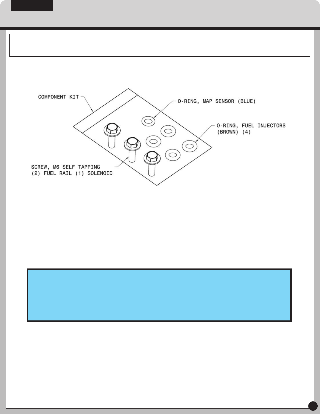
• Spare O-rings: New O-rings have been provided for your OEM fuel injectors (brown) and OEM MAP sensor
(blue). Replace O-rings carefully after parts are removed from the engine and prior to assembly of the new
manifold – take care not to cut sealing surfaces of the MAP sensor and fuel injectors when removing old
O-rings.
• Fuel Rail Installation: Make sure injectors are fully seated into the injector pockets by pushing down, directly
above each injector before securing the fuel rail. Utilize a tightening torque of approximately 5-7 Nm or until
the fuel rail is securely fastened to the intake manifold. DO NOT OVER TIGHTEN!
PLEASE WEAR
SAFETY GLASSES!
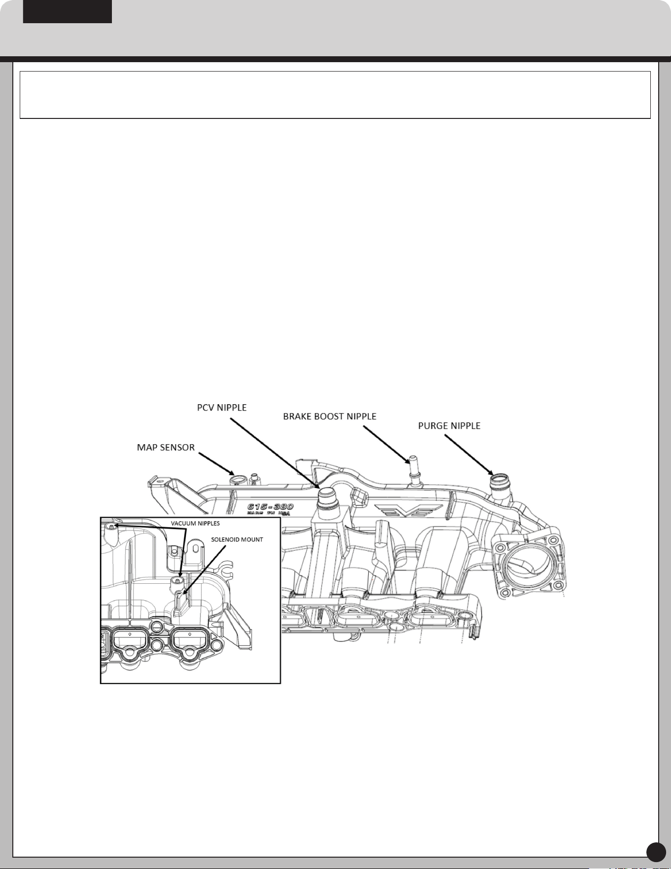
STEP 1: Carefully remove the OEM intake manifold, fuel rail, EVAP purge solenoid, throttle
body, air induction system and MAP sensor per the service procedure outlined in the shop
manual. See notes above on spare o-rings provided in kit and proper fuel rail installation.
STEP 2: Remove the six (6) mounting bolts from the OEM manifold, and install
in new manifold.
STEP 3: Clean cylinder head mounting surface to help ensure proper sealing when
installing your new manifold.
STEP 4: Slip the solenoid over the mounting feature on the underside of the manifold.
Once in place, use one of the M6 self-tapping screws to secure the solenoid to the
manifold (tighten to 5-7 Nm). DO NOT OVER TIGHTEN. Next, attach the two vacuum lines
to the vacuum nipples.
STEP 5: Attach the purge solenoid to the center clip on manifold and then attach purge
inlet hose to purge inlet nipple on the manifold.
STEP 6: Reinstall MAP sensor with the replacement o-ring. Using the original self-tapping
screw to secure the MAP sensor and tighten to 3-5 Nm. DO NOT OVER TIGHTEN.
INSTALL/REMOVAL INSTRUCTIONS: INTAKE MANIFOLD
615-380
Disclaimer:
Even though every attempt is made to ensure this information is complete and accurate, it is impossible to account for all possible circumstances or situations. Please consult with a qualied auto technician
before attempting to perform any work you are not qualied to do. Automobiles can be hazardous to work on; be sure to take all necessary safety precautions. Failure to do so may result in property damage
or personal injury. Certain motor vehicle standards and performance requirements may apply to your motor vehicle (such as Federal Motor Vehicle Safety Standards by the National Highway Trac Safety
Administration). Be sure that your work is performed in accordance with such standards and that you do not disable any motor vehicle safety feature.
ATTENTION: Refer to the appropriate shop manual for your vehicle to obtain specic service procedures for this part. If you do not have
a service manual or lack the skill to install this part, it is recommended that you seek the services of a qualied technician. Pay special
attention to all cautions and warnings included in the shop manual. Read and follow all instructions carefully.
2
©2019 Dorman Products, Inc.
No reproductions in whole or in part without prior written approval.
STEP 7: Install the fuel rail and fuel hose bracket to the manifold. Fasten the fuel rail with
two M6 self-tapping fasteners per above instructions/torque specication.
STEP 8: Reinstall the throttle body using the four stock throttle body bolts and washers,
and tighten to 9-11 Nm.
STEP 9: Bolt the manifold to the cylinder head (6 places) in two passes, using a 2 Nm
initial and 20 Nm nal tightening torque.
STEP 10: Attach the remaining engine components as per service procedure outlined in
the shop manual.
INSTALL/REMOVAL INSTRUCTIONS: INTAKE MANIFOLD
615-380
Disclaimer:
Even though every attempt is made to ensure this information is complete and accurate, it is impossible to account for all possible circumstances or situations. Please consult with a qualied auto technician
before attempting to perform any work you are not qualied to do. Automobiles can be hazardous to work on; be sure to take all necessary safety precautions. Failure to do so may result in property damage
or personal injury. Certain motor vehicle standards and performance requirements may apply to your motor vehicle (such as Federal Motor Vehicle Safety Standards by the National Highway Trac Safety
Administration). Be sure that your work is performed in accordance with such standards and that you do not disable any motor vehicle safety feature.
ATTENTION: Refer to the appropriate shop manual for your vehicle to obtain specic service procedures for this part. If you do not have
a service manual or lack the skill to install this part, it is recommended that you seek the services of a qualied technician. Pay special
attention to all cautions and warnings included in the shop manual. Read and follow all instructions carefully.
3
©2019 Dorman Products, Inc.
No reproductions in whole or in part without prior written approval.
We appreciate your opinions regarding this product!
Please call our Technical Assistant with any challenges or suggestions
regarding the installation or operation of this product.
1-800-523-2492