508636-01 Page 1 of 20
Issue 2432
Certifications .....................................................2
Shipping and Packing List ................................2
Overview...........................................................3
Operating Environment Specifications .............3
Product Features ..............................................3
Introduction .......................................................4
RDS Non-Communicationg Blower Control Board
Dimensions .......................................................5
Installation ........................................................6
Sensor Part Number Verification .................6
Mounting Methods .......................................6
Mounting Location........................................6
Condensate Safety Switch (Float Switch) ...7
Routing the Sensor Cable ............................8
Making the Connection ................................9
DIP Switch Settings ..........................................10
Modes of Operation ..........................................10
Initializing ....................................................10
Normal .........................................................10
Leak Detected ..............................................10
Fault .............................................................11
Diagnostic Codes .............................................11
Red LED Diagnostic Codes .........................11
Test Button Functionality ..................................12
Test Button - Additional Functions ...............13
Thermostat Compatibility ..................................13
Compatibility Verification ..............................14
Additional Applications......................................14
Zone HVAC System .....................................14
External Alarm .............................................14
Start Up Test Procedure ...................................15
Cooling Demand ..........................................15
Heating Demand .........................................15
Wiring Diagrams ...............................................16
Single Stage Air Conditioner with
Single Stage Indoor Unit ..............................16
Single Stage Heat Pump with Air Handler ...17
Two Stage Heat Pump with Two
Stage Furnace .............................................18
Non-Communicating Zoning Control with Single
Stage AC Unit ..............................................19
Diagnostic Codes and Troubleshooting ............20
Contents
*P508636-01*
(P) 508636-01
INSTALLATION INSTRUCTIONS
Low Global Warming Potential (GWP) Refrigerant
Detection System (RDS) Non-Communicating Blower
Control Board (24 Volts Only) Kit
This manual must be left with the homeowner for future reference.
508636-01 Page 2 of 20
Issue 2432
WARNING
Improper installation, adjustment, alteration,
ser vice or maintenance can cause property
damage, personal injury or loss of life.
Installation and service must be performed
by a li censed professional HVAC installer
(or equivalent) or a service agency.
WARNING
All systems Charged with at least 4 lbs of
low-GWP A2L-classified refrigerant are
required to have a refrigerant leak detection
system installed to prevent the build up of
A2L refrigerant in enclosed spaces of the
HVAC equipment. A refrigerant detection
system may be required for systems that
have less than 4 lbs of low-GWP refrigerant.
For more information on this, contact
Technical Support.
Installing a residential HVAC system
with A2L-classied refrigerant without a
refrigerant detection system may lead to a
fire hazard within the home in the event of a
refrigerant leak.
WARNING
The RDS Non-Communicationg Blower
Control Board has been tested with OEM
matched coils only. Do not use a non-OEM
refrigerant detection system controller or
non-OEM leak sensor with OEM coils. Do
not use the RDS Non-Communicationg
Blower Control Board with non-OEM coils or
air handlers.
WARNING
Improper installation of the RDS Non-
Communicating Blower Control Board may
lead to unreliable equipment operation and
unreliable refrigerant detection.
In addition to installing the RDS Non-
Communicationg Blower Control Board,
considerations must be made regarding
sensor mounting location. Please refer to
respective OEM air handler, coil, and/or
sensor kit installation guides for further details.
CAUTION
Any service personnel installing,
decommissioning, or performing maintenance
on the unit. It is the responsibility of the
licensed installer or service agency to obtain
the appropriate training and/or certifications
to work on A2L-classified HVAC systems with
low GWP refrigerants.
CAUTION
Unit must remain powered except for service.
Certications
• CSA C22.2 No. 60335-2-40:22; Fourth ed.
• UL 60335-2-40; Fourth ed.
Shipping and Packing List
Qty
Description Cat. No.
1 OEM
Low GWP Refrigerant
Detection System
27A05
2 Mounting Hardware -
#6-18 1” Phillips Drive pan
head with dry wall anchor
N/A
508636-01 Page 3 of 20
Issue 2432
NOTE: This kit is sold separately from the
refrigerant detection sensor. The
refrigerant sensor is included as part
of an OEM sensor kit, R454B-only
coil, or R454B-only air handler.
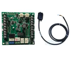
Overview
Low GWP Refrigerant Detection System,
Non-Communicati ng Blower Control Board,
ensures nominal or proper operation of the
OEM residential HVAC systems equipped with
A2L-classied refrigerant low GWP refrigerant.
The RDS Non-Communicating Blower Control
Board connects to the refrigerant detection
sensor, the indoor unit, the outdoor unit and
the thermostat to control the HVAC system in
the event refrigerant is detected by the sensor.
The RDS Non-Communicating Blower Control
Board functions with standard 24VAC or OEM
non-communicating control interfaces.
Operating Environment Specifications
The Low GWP Refrigerant Detection Kit is de-
signed to withstand the following conditions:
Condition Temperature Range
Normal Operation
-40°F - 185°F
(40°C - 85°C)
Shipping/Storage
Functional Range
Humidity
10% to 90% non-
condensing at 104°F
(40°C)
Product Features
• Detects R-454B refrigerant and helps to
prevent a concentration of refrigerant from
reaching the lower flammability limit, should
refrigerant occur in the indoor coil.
• Multicolor LED (light-emitting diode)
communicates RDS Non-Communicationg
Blower Control Board state
• Test/Reset button (to verify RDS Non-
Communicationg Blower Control Board
functionality)
• Composite case with mounting hardware for
drywall installations
• Supports up to two refrigerant detection sensors
• Supports standard 24VAC control for
split systems HVAC equipment (Single-
Stage, Two-Stage, Variable Speed, Heat
Pump, AC, Gas Furnace, Air Handler) See
“Thermostat Compatibility” on page 13.
• Compliant with UL-60355-2-40 & CSA
• Compatible with OEM approved sensor (see
“Refrigerant Detection System Sensors” on
page 7)
• Required when installing an OEM outdoor
unit that use R454B refrigerant. Some
indoor units may already feature refrigerant
detection system control functionality and
may not require this kit. “Check indoor
equipment installation guide to determine
if the system comes wit the refrigerant
detection system already installed.
508636-01 Page 4 of 20
Issue 2432
Introduction
The Low GWP Refrigerant Detection System ensures safe operation of the residential HVAC
systems equipped with low GWP A2L-classied refrigerant (R-454B).
The RDS Non-Communicationg Blower Control Board activates the blower in the event the
refrigerant concentration in the cabinet begins to rise. The control will activate the blower if the
concentration reach 12% of the lower ammability limit (LFL) whereas the UL standard is 20% of
the LFL. Power to ignition sources is also interrupted The refrigerant concentration in the cabinet
and interrupts power to ignition sources in the HVAC system when it detects a refrigerant leak in
the indoor coil.
After refrigerant concentrations have been reduced to safe levels, the RDS Non-Communicating
Blower Control Board allows the HVAC system to resume normal functionality. The HVAC system
“The RDS Non-Communicating Blower Control Board activates the blower in the event the
refrigerant concentration in the cabinet begins to rise. The control will activate the blower if the
concentration reach 12% of the lower ammability limit (LFL) whereas the UL standard is 20% of
the LFL. Power to ignition sources is also interrupted.”
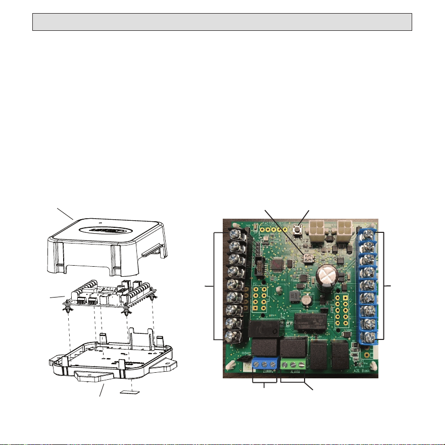
Back Plate
RDS
Wiring
Board
Cover
Sensor Selection DIP Switch
Leak Event Test Button
Thermostat &
Condenser
Unit Terminals
Indoor
Unit
Te
rminals
Zoning
Terminal
Optional Alarm
Dry Terminal
Figure 1. RDS Non-Communicating Blower Control Board
508636-01 Page 5 of 20
Issue 2432
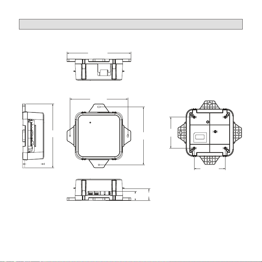
RDS Non-Communicating Blower Control Board Dimensions
(6-3/4 in.)
(7-7/16 in.)
(7-7/16 in.)
(6-3/4 in.)
(1-1/8 in.)
(1-3/8 in.)
(2-1/2 in.)
(3-5/8 in.)
(3-5/8 in.)
Top View
Front View
Side View
Boom View
Rear View
Figure 2. RDS Non-Communicating Blower Control Board Dimensions

508636-01 Page 6 of 20
Issue 2432
Installation
Sensor Part Number Verification
Verify the refrigerant detection system sensor’s
part number, which is found on the sensor/
cable, prior to installation. The part number is
107648-01.
NOTE: All sensors paired to a single RDS
Non-Communicating Blower Control
Board must share the same part
number (107648-01) to ensure the
RDS Non-Communicating Blower
Control Board will function properly.
Mounting Methods
Some mounting surfaces may be dicult to
access after the RDS Non-Communicating
Blower Control Board is installed. To avoid this
or a similar situation wire the RDS Non-Com-
municating Blower Control Board unit prior to
mounting in a conned space.
For drywall/closet installations, use the
included drywall hardware. For attic/crawl-
space/basement installations, use the included
and eld-provided hardware.
Mounting Location
The RDS Non-Communicating Blower Control
Board can be mounted to the indoor unit, ple-
num, a stud, or joist in an attic, crawlspace, or
other unnished area within 48 inches of the
refrigerant sensor cable grommet on the coil
or air handler. Drywall anchors and screws
are provided for installation in nished areas,
such as closets. Mount the RDS Non-Commu-
nicating Blower Control Board in a clean, dry
environment that is away from dust, water, and
other contaminant accumulation.
NOTE: Mounting the RDS Non-
Communicating Blower Control
Board farther than 48 inches away
from the refrigerant sensor may
prevent reliable operation due to
cable strain and water seepage on
cable connections.
• Do not place the RDS Non-
Communicating Blower Control Board in
secondary drain pan
• Use the screws provided to mount the
RDS Non-Communicating Blower Control
Board
• Tighten the screws to a snug fit
NOTE: Do not over-tighten the screws.
Over-tightening the screws may strip
the hardware and apply excessive
stress on the enclosure.
Refrigerant Detection System Sensor
(sold separately)
The refrigerant detection system sensor must
be mounted as specied in its accompanying
manual. Mounting the sensor incorrectly or in
an improper location may result in refrigerant
detection failure.

508636-01 Page 7 of 20
Issue 2432
Condensate Safety Switch (Float Switch)
In applications that require a condensate safety switch (oat switch) the oat switch must be
wired between the room thermostat and the Refrigerant Detection System. The oat switch’s
normally closed contacts may be wired to interrupt the “R” wire or the “Y” wire between
the thermostat and the RDS Non-Communicating Blower Control Board. See the RDS
Non-Communicating Blower Control Board wiring diagrams. This ensures the RDS Non-
Communicating Blower Control Board is powered continuously and operates normally. Do
not wire the condensate safety switch or any other eld installed safety switches between the
indoor unit transformer and the RDS Non-Communicating Blower Control Board. The RDS
Non-Communicating Blower Control Board must remain powered at all times.
Refrigerant Detection System Sensors
The OEM Refrigerant Detection System requires an OEM RDS sensor located in the indoor
coil. See table below.
Indoor Unit Model RDS Sensor Catalog No. Description
• 7EC/NCU/BC7 Upow
• 7EH/NCH/BC7 Horizontal
• 7ED/NCD/BC7 Downow
"Revision 01" Coils
26Z69
Refrigerant Detection System (RDS)
Coil Sensor Kit
• 7AH1AC/NAM/BHA/HMA
• 7AH1AE/NAM/BHA/HMA
• 7AH1AV /NAM/BHA/HMA
• 7AH2AE /NAM/BHA/HMA
"Revision 01" Air Handlers
27J27 RDS Air Handler Sensor Kit
• 7EC/NCU/BC7 Upow
• 7EH/NCH/BC7 Horizontal
• 7ED/NCD/BC7 Downow
"Revision 71" Coils
Factory Installed
RDS Sensor is Factory Installed
in "Revision 71" Coils
All R-454B Coils & Air Han-
dlers
27V53
Coil Sensor Repair Kit
(Replacement Sensor only, without
mounting bracket & components pro-
vided in the Sensor Kit)
508636-01 Page 8 of 20
Issue 2432
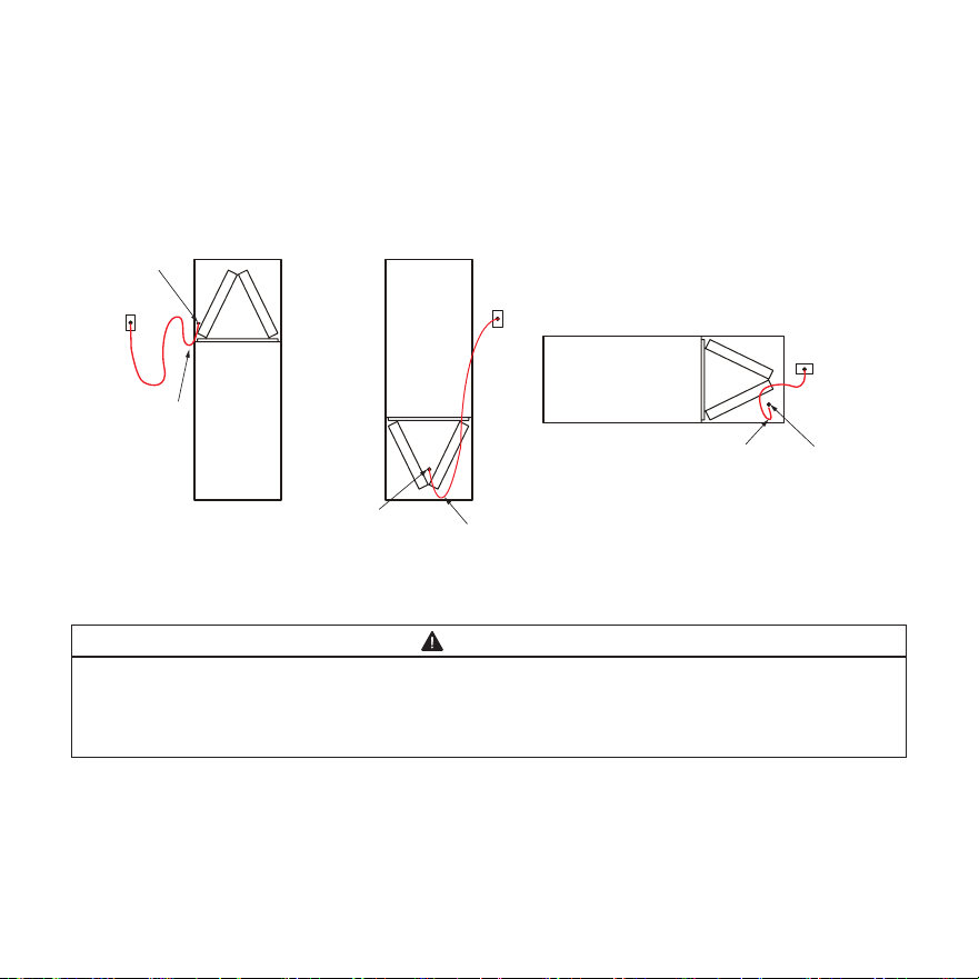
Routing the Sensor Cable
Figure 3 illustrates how to best route the sensor cable from the RDS Non-Communicating Blower
Control Board to the sensor within the indoor unit for the Upow, Downow, and Horizontal ori-
entations. For details on mounting the sensor itself, refer to the respective sensor kit, air handler,
or coil installation guide.
UPFLOW INDOOR UNIT
DOWNFLOW INDOOR UNIT
HORIZONTAL INDOOR UNIT
RDS
RDS
RDS
COIL
COIL
COIL
DRIP LOOP
DRIP LOOP
DRIP LOOP SENSOR CABLE
DRILL OUT
SENSOR CABLE
DRILL OUT
SENSOR CABLE
DRILL OUT
Figure 3. Routing the Sensor Cable
WARNING
Do not strap the RDS Non-Communicating Blower Control Board to existing tubing or other
electrical cables” with the following “Do not strap the RDS Non-Communicating Blower
Control Board to existing tubing or other electrical cables, since they are not designed to
have equipment strapped to them and can cause them to become disconnected.
508636-01 Page 9 of 20
Issue 2432
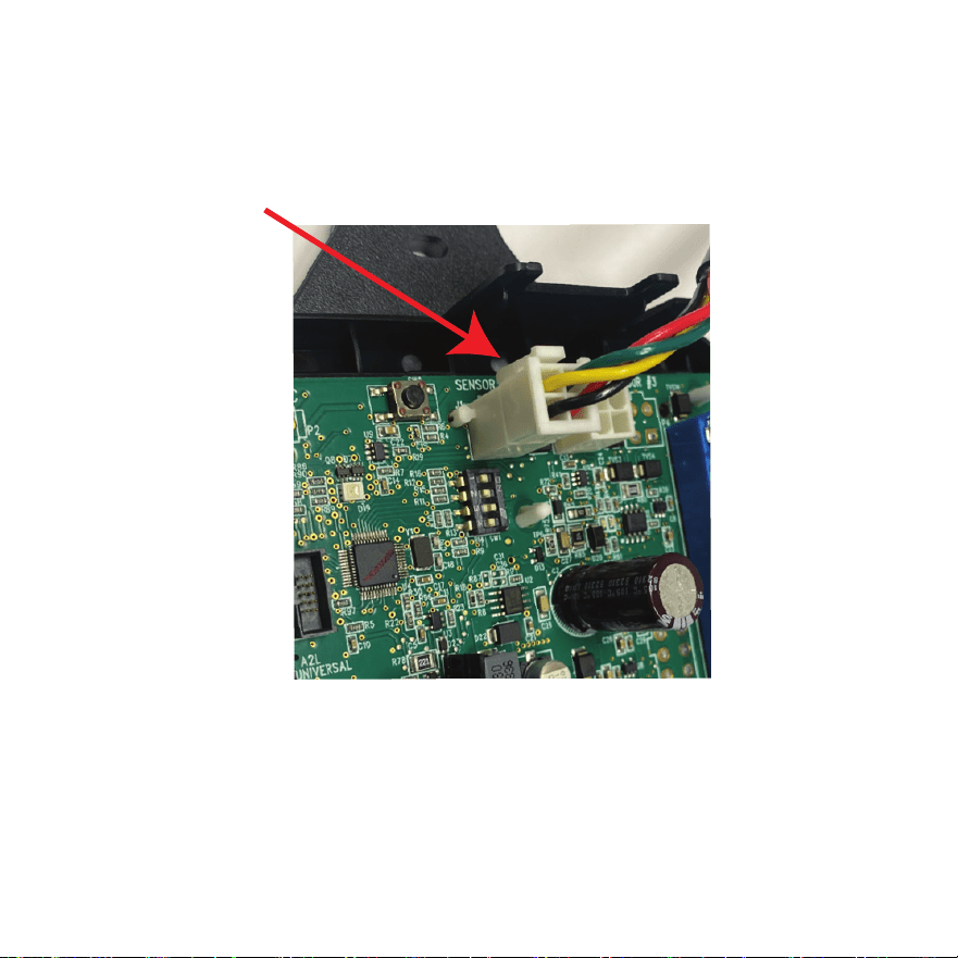
Making the Connection
Ensure the cable is properly connected into the number one (1) sensor plug. The Molex plug clip
should lock into the Molex connection point for a secured connection, as shown below in Figure
4. Verify the connection is free of dust, debris, and moisture.
Molex Plug Clip
Figure 4. Connecting the RDS Sensor to RDS Non-Communicating Blower Control Board
508636-01 Page 10 of 20
Issue 2432
DIP Switch Settings
Adjust the DIP switch settings to the sensor
conguration. Failure to do so will cause faults
on power-up.
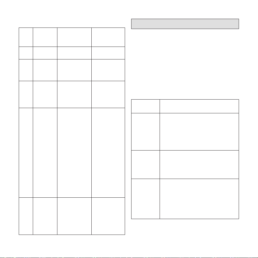
Table 1. DIP Switch Settings
Configuration DIP1 DIP2
Two (2) sensors expected;
in connector 1 and 2
OFF OFF
One (1) sensor expected;
in connector 1
OFF ON
Congurations other than the ones shown
above will cause a service fault.
Each DIP switch corresponds to a sensor
position (i.e., DIP switch 1 to sensor 1; DIP
switch 2 to sensor 2). The default factory switch
positions are set to OFF. The RDS software
reads the OFF position as an active sensor. A
sensor should be present for the corresponding
sensor connector. Setting the DIP switch to ON
disables the sensor position.
NOTE: Refer to 508467-01 (Installation
Instructions for Refrigerant Leak
Detection Sensor Kit - Indoor Coils)
to determine whether more than
one (1) Refrigerant Leak Detector
Sensor is required.
Modes of Operation
The modes of operation for the RDS Non-
Communicating Blower Control Board are
Initializing, Normal, Refrigerant Detected, and
Fault.
Initializing
The RDS Non-Communicating Blower Control
Board is establishing connection with the
refrigerant detection sensor and is completing
an initial ve (5) minute purge sequence.
Normal
The HVAC system is functioning normally.
The RDS Non-Communicating Blower Control
Board has not detected refrigerant.
Refrigerant Detected
When the RDS Non-Communicating Blower
Control Board detects refrigerant :
1. The RDS Non-Communicating Blower
Control Board shuts o the (R) input
(24VAC power) to the thermostat,
which de-energizes the outdoor unit
compressor and heat sources, such as
gas and/or electric strip heat. No heating
or cooling demands will be met.
2. The RDS Non-Communicating Blower
Control Board activates the blower (high
speed). The blower purges refrigerant
from the cabinet, plenum, and ductwork.
3. After the RDS Non-Communicating
Blower Control Board determines the
refrigerant levels are below the safety

508636-01 Page 11 of 20
Issue 2432
threshold, the blower will continue to
function for an additional seven (7)
minutes.
4. After the blower sequence is complete, the
HVAC system resumes normal operation.
NOTE: The HVAC system may not
maintain a cooling or heating
setpoint if a significant leak exists.
Any refrigerant leaks that remain
unaddressed for an extended time
may cause the HVAC system to
shut down on a low refrigerant
pressure limit condition.
Fault
When a fault is detected within the RDS
Non-Communicating Blower Control Board,
the indoor unit blower engages and remains
engaged at a constant output until the fault is
cleared.
Diagnostic Codes
The RDS Non-Communicating Blower Control
Board is equipped with a multicolor LED with-
in its enclosure. The LED signals the state of
the RDS Non-Communicating Blower Control
Board.
See Table 2 to review the diagnostic codes.
Table 2. LED Diagnostic Codes
State LED
Diagnostic
Code
Action
Initializing
Flashing
green¹
Not Applicable
Monitoring
Solid green with
blue flash²
Not Applicable
Mitigating
(Refrigerant
Detected)
Flashing blue
Check coil
tubes for leak.
Repair the issue
and restart the
equipment.
Fault/Service
Solid blue, inter-
rupted by issue
flash code
Refer to
Table 7 for
troubleshooting
steps.
1. A rapid flash indicates the RDS Non-Communicating
Blower Control Board is in the process of sensor
enumeration
2. A blue flash indicates the mitigation process has
previously occurred.
Red LED Diagnostic Codes
Red diagnostic codes indicate a specic RDS
Non-Communicating Blower Control Board is-
sue. Yellow diagnostic codes indicate the sen-
sor’s position (if applicable).
Table 3. Red LED Diagnostic Codes
Red
Flash
Applies to
Individual
Sensor(s)
Issue Action
1 Yes
Sensor indicates
fault
Replace the
sensor
(Cat. # 26Z69)
508636-01 Page 12 of 20
Issue 2432
Table 3. Red LED Diagnostic Codes
Red
Flash
Applies to
Individual
Sensor(s)
Issue Action
2 No
Spare Code -
Unused
Not Applicable
3 Yes
Incompatible
sensor type
Replace with
a compatible
sensor
(Cat. # 26Z69)
4 Yes
Sensor
communications
issue
Check sensor
connection.
Ensure
connection is
clean and tight.
5 No
R-input not
available
Check for
24VAC power
connection to
the R terminal
inputs on the
RDS Non-
Communicating
Blower Control
Board. R-inputs
must be
energized for
the RDS Non-
Communicating
Blower Control
Board to
function.
6 No
Invalid
configuration of
sensor count
Verify the DIP
switch setting
is correct and
matches the
number of
sensors being
used.
Test Button Functionality
The RDS Non-Communicating Blower Control
Board is equipped with a Test/Reset button.
The Test button can be used to complete sev-
eral functions, depending on the mode of oper-
ation of the RDS Non-Communicating Blower
Control Board, .
Table 4 lists the functions of the Test button
during each mode of operation.
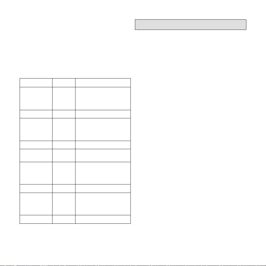
Table 4. Test Button Function
Mode of
Operation
Press the Test Button to...
Normal
Trigger a Refrigerant detection
response.
Verify all equipment is wired
correctly into the RDS Non-
Communicating Blower Control
Board (after installation).
Refrigerant
Detected
Reset the RDS Non-Communicating
Blower Control Board to a normal
mode of operation after refrigerant
has been detected and purged from
the HVAC system.
Fault
Reset the RDS Non-Communicating
Blower Control Board after
troubleshooting and resolving a fault
condition. If the fault is not resolved,
the RDS Non-Communicating
Blower Control Board will enter the
Fault mode again.
508636-01 Page 13 of 20
Issue 2432
Test Button - Additional Functions
Table 5 lists the additional functions of the Test
Button while the RDS Non-Communicating
Blower Control Board, is functioning within the
states of Initializing, Monitoring, Refrigerant
Detection, Servicing and Fault. Refer to “Table
2. LED Diagnostic Codes” on page 11.
Table 5. Additional Button Functions
State Press Action
Initializing Short Skips remaining pre-
purge after sensors
are recognized by the
RDS
Initializing Long Reset control
Monitoring Short Clear purge-counter
if prior mitigation has
occurred; Test miti-
gation
Monitoring Long Reset control
Mitigating Short If testing mitigation,
end test
Servicing Short Reevaluate fault condi-
tion - if cleared return to
monitoring, otherwise
update indicator
Servicing Long Reset control
Fault Short Reevaluate fault condi-
tion - if cleared return to
monitoring, otherwise
update indicator
Fault Long Reset control
Thermostat Compatibility
Thermostats that preserve memory settings are
compatible with the RDS Non-Communicating
Blower Control Board. Examples include:
• Battery-powered thermostats
• Analog thermostats
• Smart thermostats
• Late-model programmable thermostats
NOTE: Early-generation digital and
programmable thermostats may
not retain the operation mode and
temperature setpoints after a power
outage.
The following scenarios are likely to occur
when home occupants are not available to
adjust the thermostat setpoints as the system
is recovering from refrigerant detection and
resuming normal operation:
• Heating could be lost during a cold night
• Cooling could be lost during a hot day
• The thermostat could reset to an incorrect
temperature setpoint

508636-01 Page 14 of 20
Issue 2432
Compatibility Verification
Complete the following process to determine
whether the thermostat is compatible with
the RDS Non-Communicating Blower Control
Board.
1. Change the thermostat’s current setpoint
and operating mode.
2. Power cycle the breaker to the furnace or
air handler.
NOTE: Wait five (5) minutes before
supplying power to the furnace or air
handler breaker.
3. Note whether the thermostat maintained
its setpoints and operating mode.
a. If the thermostat maintained the
settings, the thermostat is compatible
with the RDS Non-Communicating
Blower Control Board.
b. If the thermostat did not maintain its
setpoint and/or operating mode, the
thermostat is not compatible with the
RDS Non-Communicating Blower
Control Board. Recommend replacing
with a compatible thermostat.
Additional Applications
In zoned applications, all dampers will remain
open when the RDS Non-Communicating
Blower Control Board is in Fault or Refrigerant
Detected mode. Normal heating and cooling
demands are permissible, but the blower will
remain engaged until the fault condition is
addressed.
Zone HVAC System
If the RDS Non-Communicating Blower Control
Board is installed in a zone HVAC system,
the RDS Non-Communicating Blower Control
Board will open all zone dampers if refrigerant
is detected.
NOTE: Proper wiring of the zone panel to the
RDS Non-Communicating Blower Control
Board is required for all zone dampers
to open.
After the purge sequence is complete, the zone
system will resume normal operation.
External Alarm
(For applications with external alarms wired di-
rectly to the RDS Non-Communicating Blower
Control Board.)
The RDS Non-Communicating Blower Control
Board triggers the external alarm system when
it enters Refrigerant Detected mode. For alarm
notications, the RDS Non-Communicating
Blower Control Board provides a dry relay
contact that is rated 3A at 30 VAC/DC.

508636-01 Page 15 of 20
Issue 2432
Start Up Test Procedure
The RDS Non-Communicating Blower Control
Board is equipped with a Test/Reset button,
see “Test Button Functionality” on page 12.
After the RDS Non-Communicating Blower
Control Board has been mounted and wired,
restore power to the HVAC system. The system
will then run through a purge sequence for ve
(5) minutes. After the purge sequence is com-
plete, proceed to testing cooling demand and
heating demand.
Cooling Demand
1. Prompt a cooling demand at the
thermostat.
2. Press the Test button on the RDS Non-
Communicating Blower Control Board.
The system then executes a refrigerant
detection response.
3. Observe the following sequence:
a. The LED indicator flashes the sequence
for refrigerant detection (flashing blue).
b. The blower powers up.
c. The outdoor compressor powers down.
4. Press the Test button to terminate the
simulated Refrigerant Detected mode
upon test completion.
Heating Demand
1. Prompt a heating demand at the
thermostat.
2. Observe the following sequence:
a. The LED indicator flashes the sequence
for refrigerant detection (flashing blue).
b. The blower powers up.
c. The gas burners power down.
d. The outdoor compressor powers down.
3. Press the Test button to terminate the
simulated Refrigerant Detected mode
upon test completion.
The installation of the RDS Non-Communicat-
ing Blower Control Board is complete after both
sequences are successfully completed.
508636-01 Page 16 of 20
Issue 2432
Wiring Diagrams
OEM provides wires designated for wiring the sensor cable. Wires required for the RDS installa-
tion is eld supplied.
The RDS supports OEM and non-OEM split gas furnace installations. Wiring diagrams are pro-
vided for several common split furnace system congurations to identify exact wire types and
terminal locations.
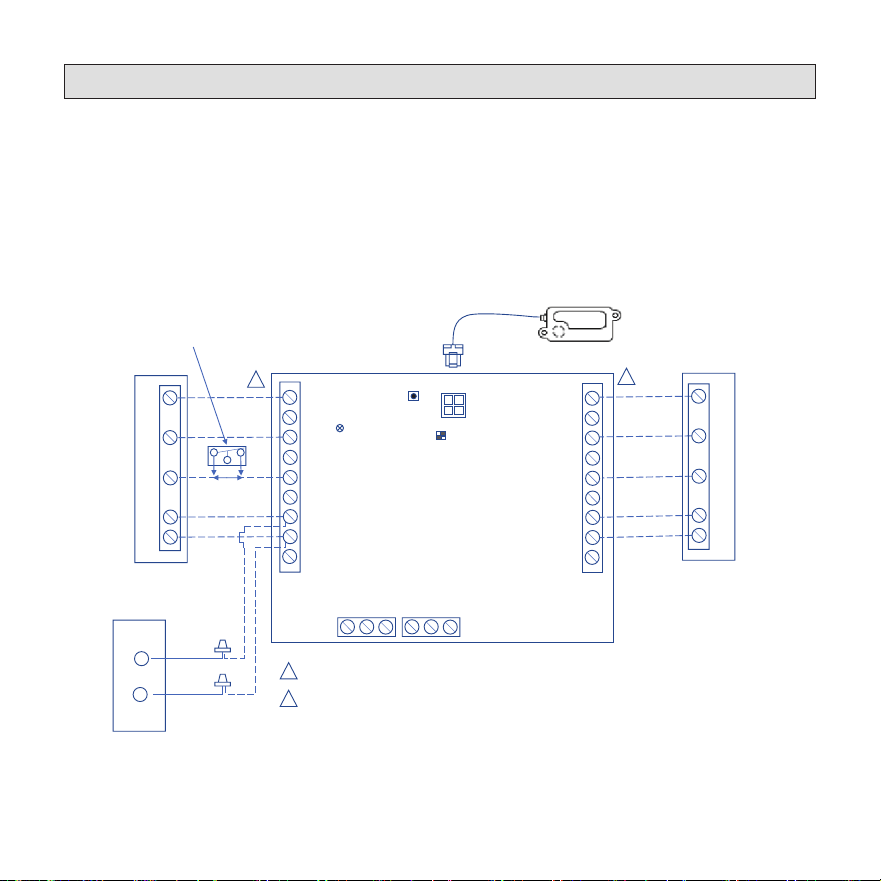
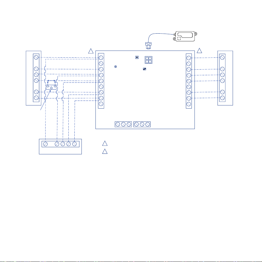
Single Stage Air Conditioner with Single Stage Indoor Unit
TSTAT
INDOOR
NO COM NC
NO COM NC
ZONING
ALARM
W1
W2
G
R
O/B
DS
C
Y2
Y1
W1
W2
G
R
O/B
DS
C
Y2
Y1
SENSOR #1
SW1
SW2
LED
W1
C
G
R
Y1
Y1
C
Thermostat
W1
C
G
R
Y1
Indoor Unit
Outdoor Unit
1
2
1
2
Thermostat / Outdoor Unit Terminal Block (BLACK)
Indoor Unit Terminal Block (BLUE)
Black
Yellow
RDS Sensor
Single Stage Furnace /
Single Stage Air Handler
RDS Field Kit – 24 Volt
Cat # (27A05)
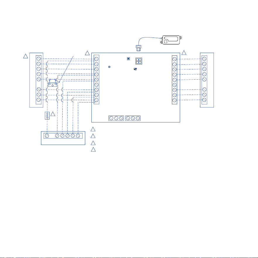
OPTIONAL
N.C. CONDENSATE
FLOAT SWITCH
508636-01 Page 17 of 20
Issue 2432
Air Handler
1
2
Thermostat / Outdoor Unit Terminal Block (BLACK)
Indoor Unit Terminal Block (BLUE)
Single Stage Heat Pump
TSTAT
INDOOR
NO COM NC
NO COM NC
ZONING
ALARM
W1
W2
G
R
O/B
DS
C
Y2
Y1
W1
W2
G
R
O/B
DS
C
Y2
Y1
SENSOR #1
SW1
SW2
LED
W1
C
G
R
O
Y1
W1
C
G
R
O
Y1
W1
C
O
Y1
R
2
1
RDS Sensor
Thermostat
RDS Field Kit – 24 Volt
Cat # (27A05)
OPTIONAL
N.C. CONDENSATE
FLOAT SWITCH
Single Stage Heat Pump with Air Handler
508636-01 Page 18 of 20
Issue 2432
Two Stage Heat Pump with Two Stage Furnace
Two Stage
Gas Furnace
3
A Dual Fuel Thermostat is Required for Dual Fuel Applicaon & will need to be programmed for dual fuel
TSTAT
INDOOR
NO COM NC
NO COM NC
ZONING
ALARM
W1
W2
G
R
O/B
DS
C
Y2
Y1
W1
W2
G
R
O/B
DS
C
Y2
Y1
SENSOR #1
SW1
SW2
LED
W1
W2
C
G
R
O
Y1
Y2
W1
W2
C
G
R
O
Y1
Y2
W1
C
O
Y1
R
Y2
Two Stage Heat Pump
Thermostat
2
1
1
Thermostat / Outdoor Unit Terminal Block (BLACK)
2
Indoor Unit Terminal Block (BLUE)
RDS Sensor
3
4
4
Defrost Tempering Kit is required for Dual Fuel Applicaon
Defrost
Tempering
Kit
RDS Field Kit – 24 Volt
Cat # (27A05)
OPTIONAL
N.C. CONDENSATE
FLOAT SWITCH
508636-01 Page 19 of 20
Issue 2432
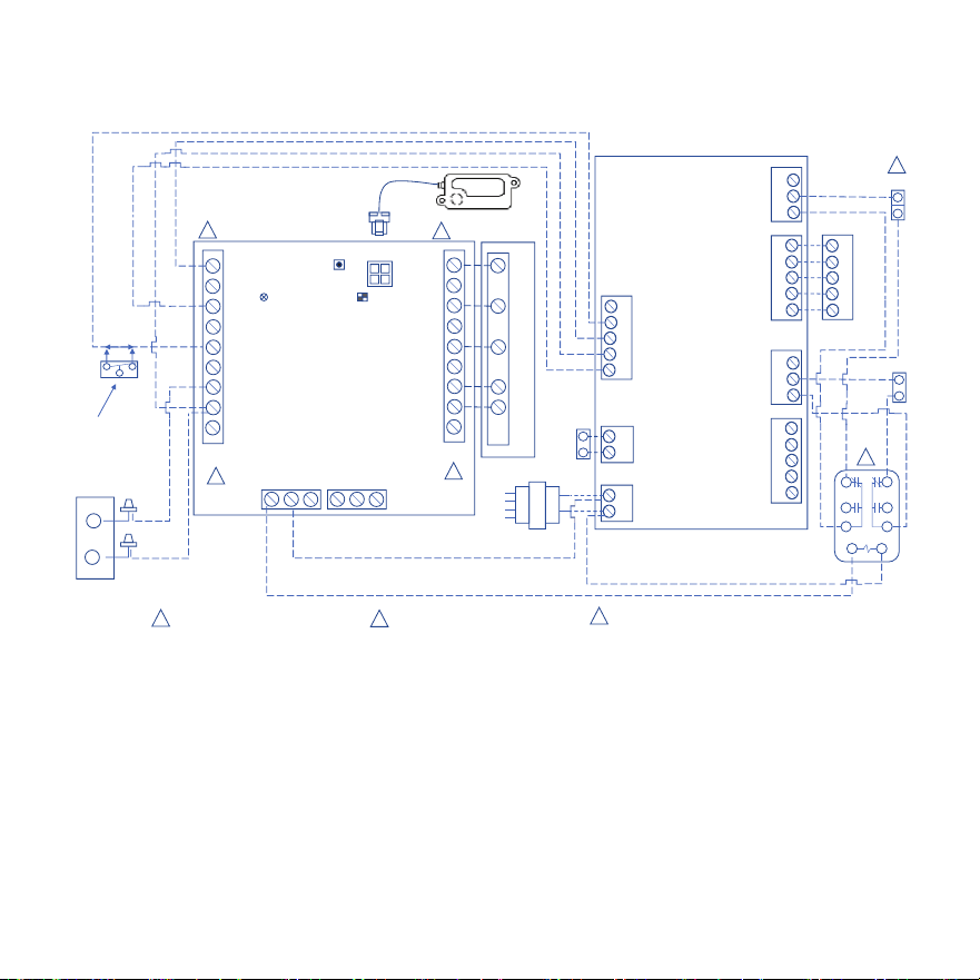
Outdoor Unit
TSTAT
NO COM NC
NO COM NC
ZONING
ALARM
W1
W2
G
R
O/B
DS
C
Y2
Y1
INDOOR
W1
W2
G
R
O/B
DS
C
Y2
Y1
SENSOR #1
SW1
SW2
LED
RDSSensor
W1
C
G
R
Y1
24 Volt Transformer
240V
208V
Com
120 V
R
C
DAT
RH
RC
W
G
Y
NC
NO
C
DAMPER 1
R
C
W
G
Y
ZONE 1THERMOSTAT
NC
NO
C
DAMPER 1
R
C
W
G
Y
ZONE 1THERMOSTAT
DATS
ZONE CONTROLPANEL
Y1
C
Black
Yellow
Indoor Unit
BA
1
4
3
7
9
6
R
C
W
G
Y
ZONE 1THERMOSTAT
Damper 2
Damper 1
C# 67K65
1
2
3
3
RDS Field Kit–24 Volt
Cat#(27A05)
1
2
OPTIONAL
N.C. CONDENSATE
FLOATSWITCH
Thermostat / Outdoor Unit
Terminal Block (BLACK)
1
Indoor Unit Terminal Block
(BLUE)
2
3
For Non-Lennox Dampers: The relay must
be wired as “Powered Open.”
Non-Communicating Zoning Control with Single Stage AC Unit,
Indoor Unit, and Thermostat
OEM
508636-01 Page 20 of 20
Issue 2432
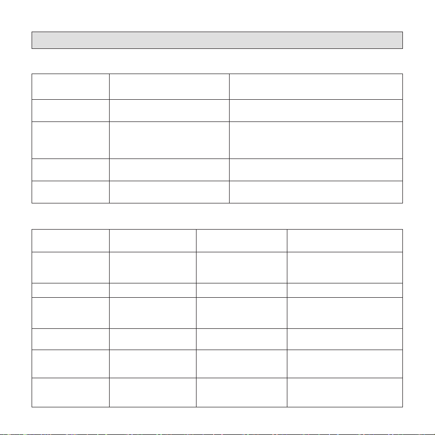
Diagnostic Codes and Troubleshooting
Table 6. LED Diagnostic Codes
State LED Diagnostic Code Action Required
Initializing Flashing green None
Monitoring
Solid green.
If a prior mitigation occurred, a
blue flash interrupts the solid
green LED.
None
Mitigating
(Leak Detected)
Flashing blue
Check coil tubes for leak. Repair the issue and
restart the equipment.
Fault/Service
Solid blue, interrupted by issue
diagnostic code
Refer to Table 7 for
troubleshooting steps.
Table 7. Red LED Diagnostic Codes / Troubleshooting
Red Flash Applies to Individual
Sensor(s)
Issue Action Required
1 Yes
Sensor indicates fault
Replace the sensor
(See “Refrigerant Detection
System Sensors” on page 7.)
2 No
Spare Code - Unused
Not Applicable
3 Yes
Incompatible sensor type
Replace the sensor
(See “Refrigerant Detection
System Sensors” on page 7.)
4 Yes
Sensor communications
issue
Check sensor connection. Ensure
connection is clean and tight.
5 No R-input not available
Check sensor connections.
Ensure connection is clean and
tight.
6 No
Invalid configuration of
sensor count
Verify the DIP switch setting is
correct and matches the number
of sensors being used.