10022116 Rev-D
Installation Manual
(For a single or dual gate installation)
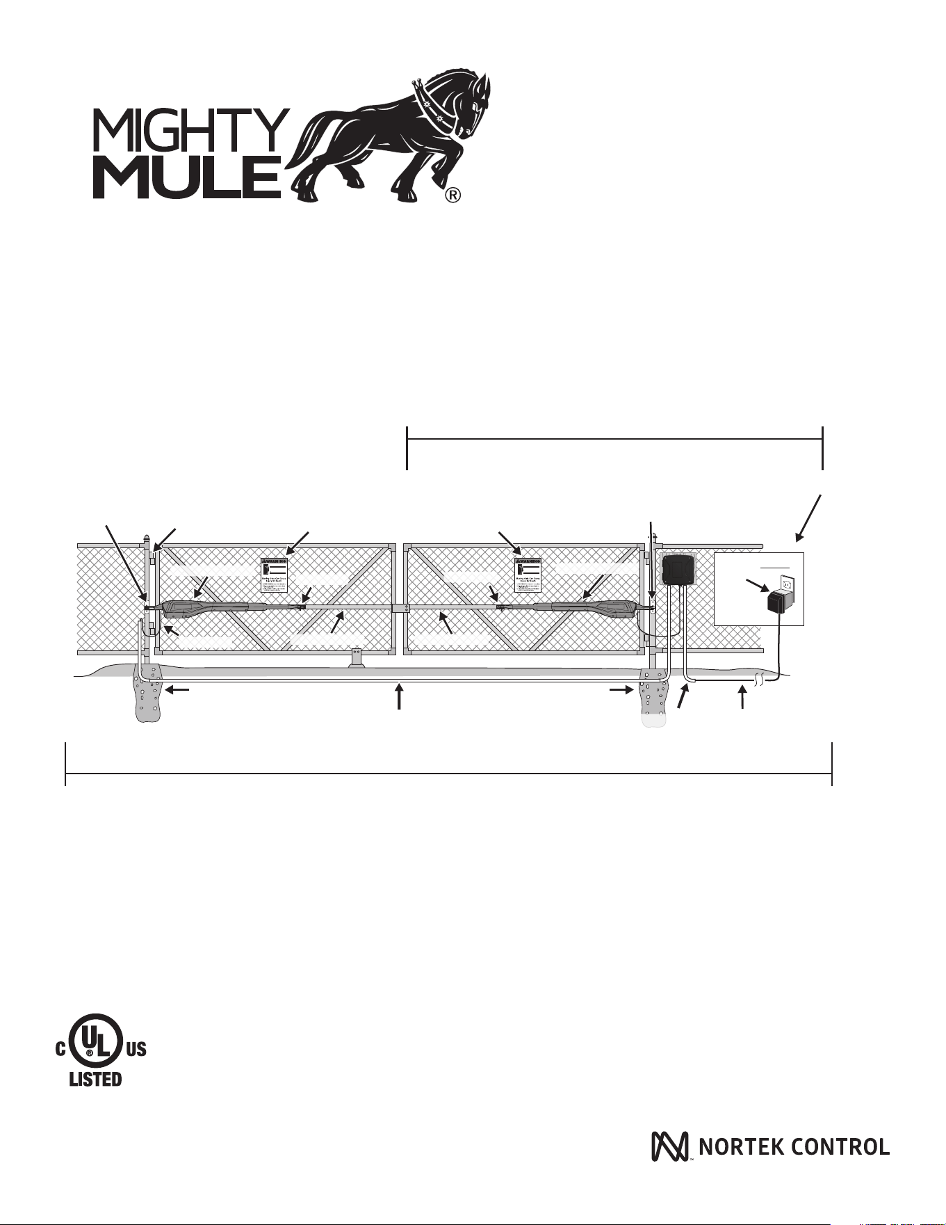
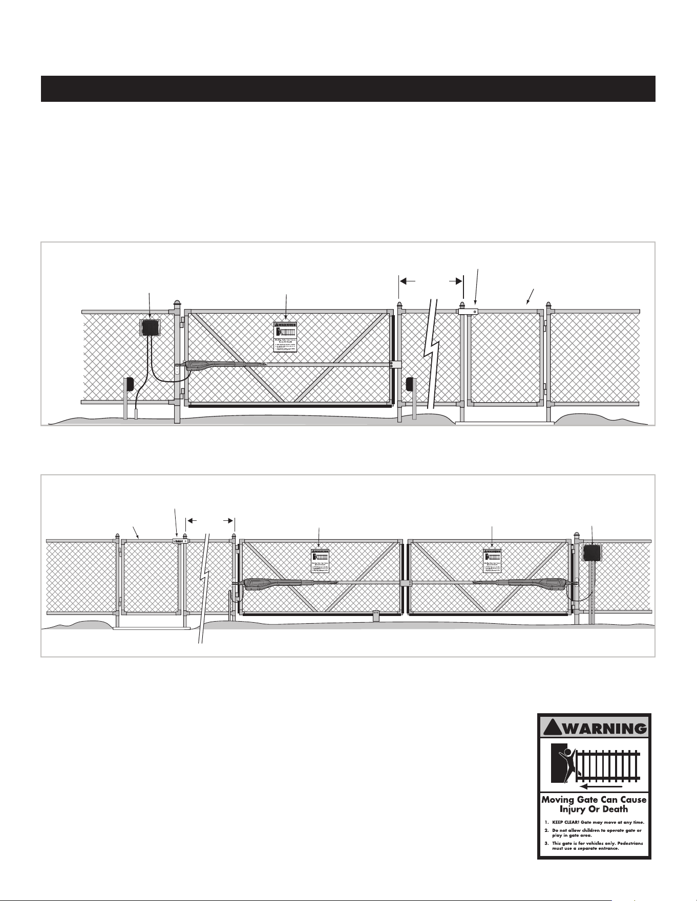
Horizontal Support
Gate Swings Evenly and Freely
Hung Firmly and Plumb
Post Bracket
Fence Post Set in Concrete Fence Post Set in Concrete
Run 1000' (max.) of low voltage
wire to control box from
transformer (wire not included).
Power Cable
PVC conduit (not included)
to protect wire from lawn
mowers and weed eaters.
PVC conduit (not included)
to run second opener power
cable under driveway.
Gate Bracket
Warning Sign
Secondary Opener
Primary Gate Opener
Horizontal Support
Post Bracket
Gate Bracket
Warning Sign
Control Box
(
mounted on wood)
120 Volt indoor
Transformer
(surge protector
not supplied)
Example of Dual Gate nished installation
(Installations vary slightly on different types of gates)
MM571W
MM572W
Single Gate Installation [MM571W]
Dual gate installation [MM572W]
This product meets the requirements of UL325, the standard for gate operator safety.
Mighty Mule® is the retail brand of Nortek Security & Control, LLC

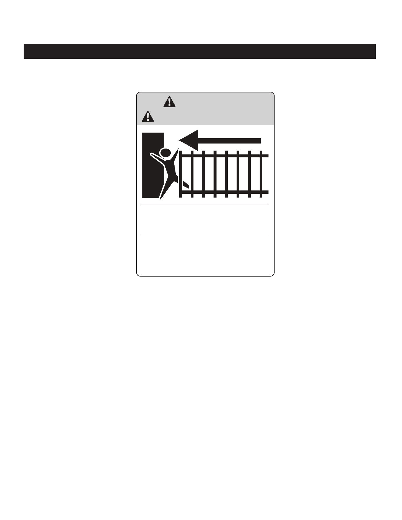
WARNING
DO NOT SPLICE ANY
POWER WIRES!
DO NOT MODIFY THE
BATTERY HARNESS!
THIS WILL VOID YOUR
MANUFACTURER’S
WARRANTY.
Low voltage wire for transformer not included.
Product Usage
The Mighty Mule Gate Operator meets all of the safety requirements of a Class I Residential Vehicular Gate Operator and is intended for use solely
with vehicular swing gates in single-family residential applications that meet the Class I category listed in the table below.
Residential Vehicular Gate Operator-Class I:
A vehicular gate operator (or system) intended for
use in garages or parking areas associated with a
residence of one-to-four single families.
Commercial/General Access Vehicular Gate
Operator-Class II:
A vehicular gate operator (or system) intended for
use in a commercial location or building such as a
multi-family housing unit (ve or more single family
units), hotel, garages, retail store, or other buildings
accessible by or servicing the general public.
Industrial/Limited Access Vehicular Gate Operator–Class III:
A vehicular gate operator (or system) intended for use in an industrial
location or building such as a factory or loading dock area or other
locations not accessible by or intended to service the general public.
Restricted Access Vehicular Gate Operator – Class IV:
A vehicular gate operator (or system) intended for use in an industrial
location or building such as a factory or loading dock area or other
locations not accessible by or intended to service the general public.
Vehicular Gate Operator Class Categories
WARNING
This equipment meets Underwriters Laboratory Standard 325 (UL 325). However, gate equipment has
hazards associated with its use and therefore by installing this product the installer and user accept
full responsibility for following and noting the installation and safety instructions. Failure to follow
installation and safety instructions can result in hazards developing due to improper assembly. You
agree to properly install this product and that if you fail to do so Nortek Security & Control, LLC, shall
in no event be liable for direct, indirect, incidental, special or consequential damages or loss of prots
whether based in contract tort or any other legal theory during the course of the warranty or at any time
thereafter. The installer and/or user agree to assume responsibility for all liability and use of this product
releasing Nortek Security & Control, LLC, from any and all liability. If you are not in agreement with this
disclaimer or do not feel capable of properly following all installation and safety instructions you may
return this product for full replacement value.
READ ALL INSTRUCTIONS CAREFULLY AND COMPLETELY before attempting to install and
use this automatic gate operator. This gate operator produces a high level of force. Stay clear of the unit
while it is operating and exercise caution at all times.
ALL AUTOMATIC GATE OPERATORS ARE INTENDED FOR USE ON VEHICULAR GATES ONLY.

Table of Contents
Please Read This First! .......................................................................................................................... 2
Important Safety Information ................................................................................................................. 3
Manually Opening and Closing Gate .................................................................................................................................................3
For the Installer and End User ...........................................................................................................................................................4
Installing Warning Signs and Pedestrian Gates .................................................................................................................................8
Required Safety Precautions for Gates ..............................................................................................................................................9
Technical Specications ...................................................................................................................... 10
Mighty Mule 571W/572W Gate Opener ...........................................................................................................................................10
Powering Options ...........................................................................................................................................................................11
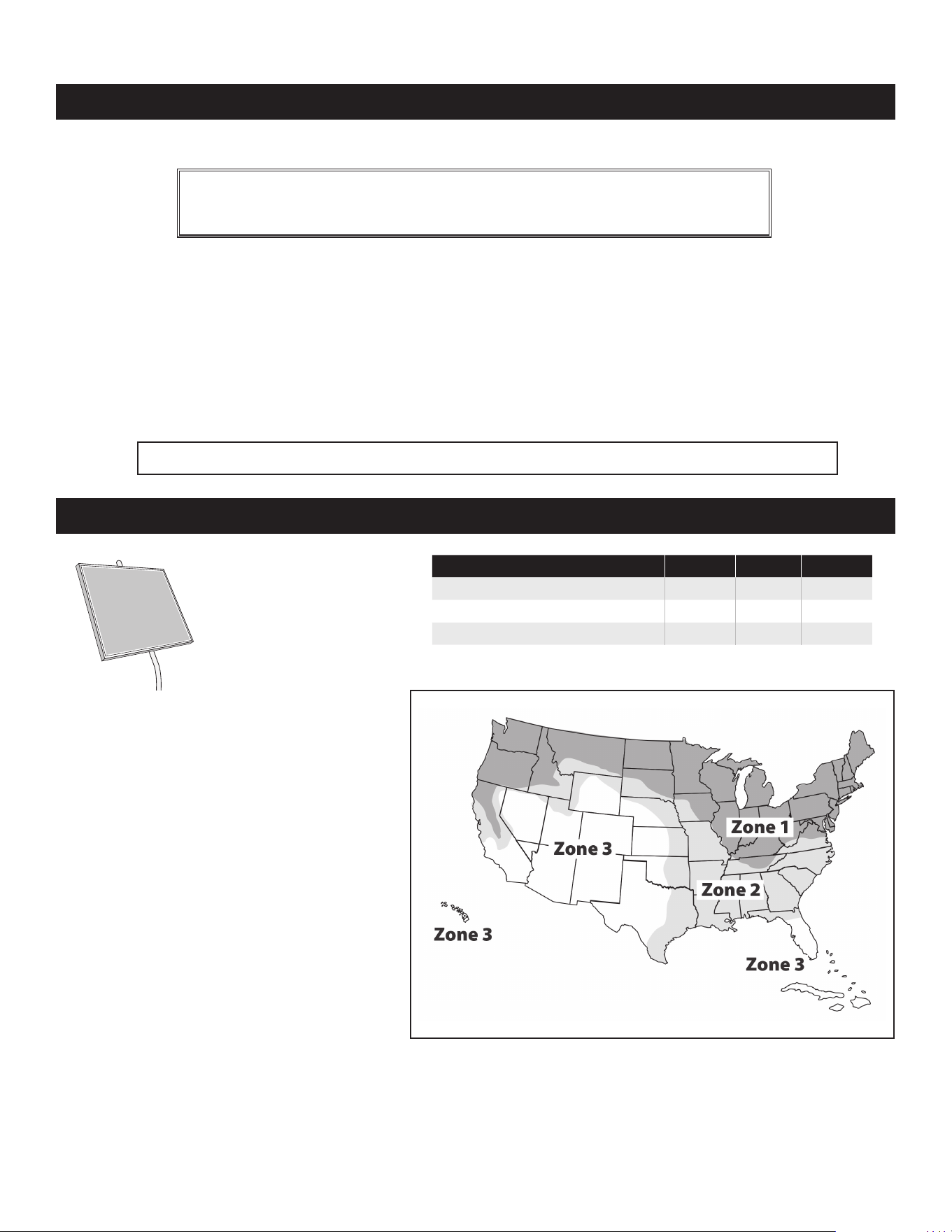
Solar Panel and Gate Activity Chart .................................................................................................................................................11
Before You Begin .................................................................................................................................. 11
Check Existing Gate Size and Material ............................................................................................................................................12
IMPORTANT: Check for Proper Gate Installation ...............................................................................................................................12
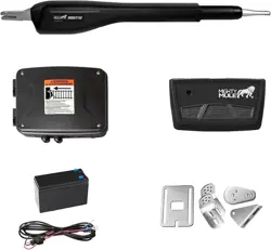
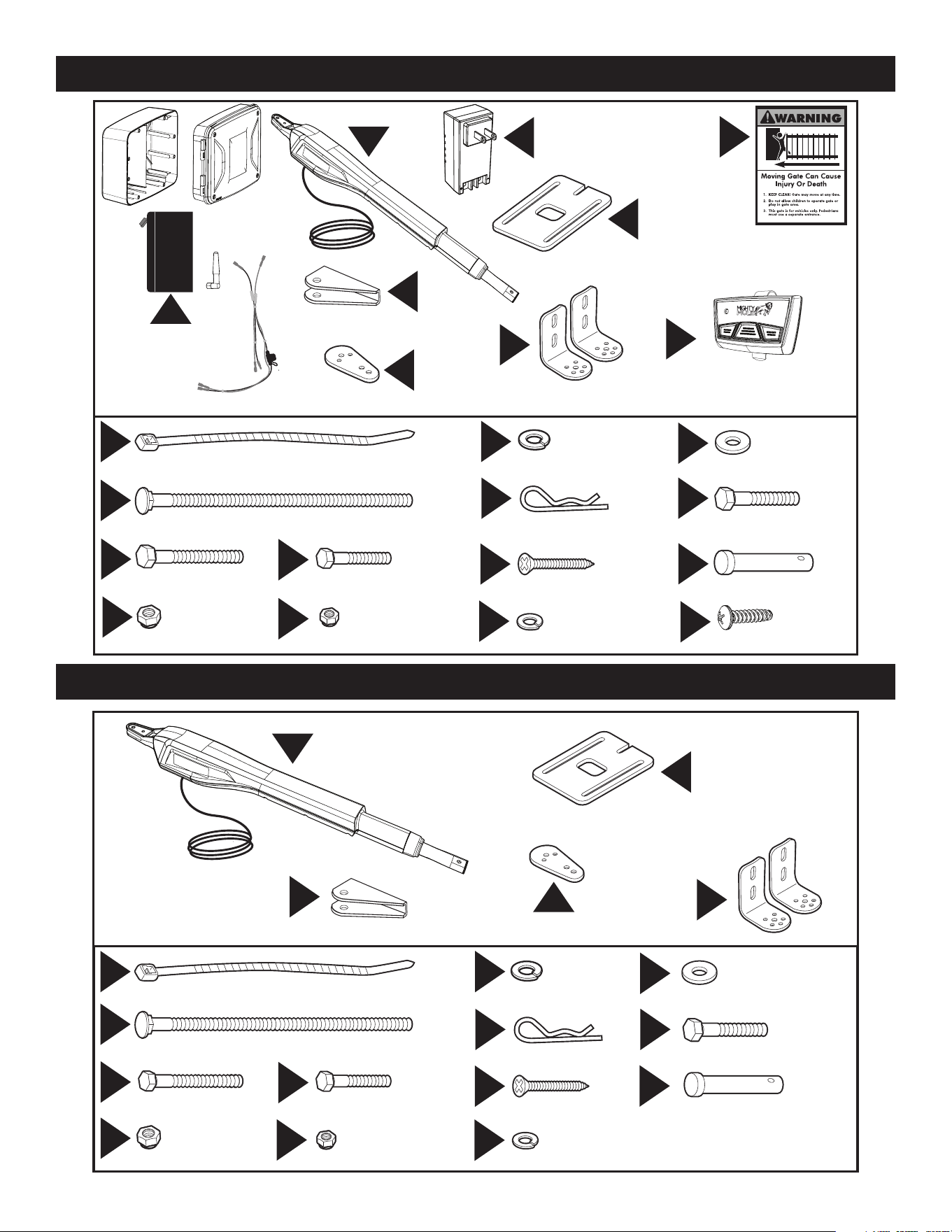
Items Included for Primary Gate Opener Installation (MM571W) ......................................................................................................13
Items Included for Secondary Opener Installation (MM572W) .........................................................................................................13
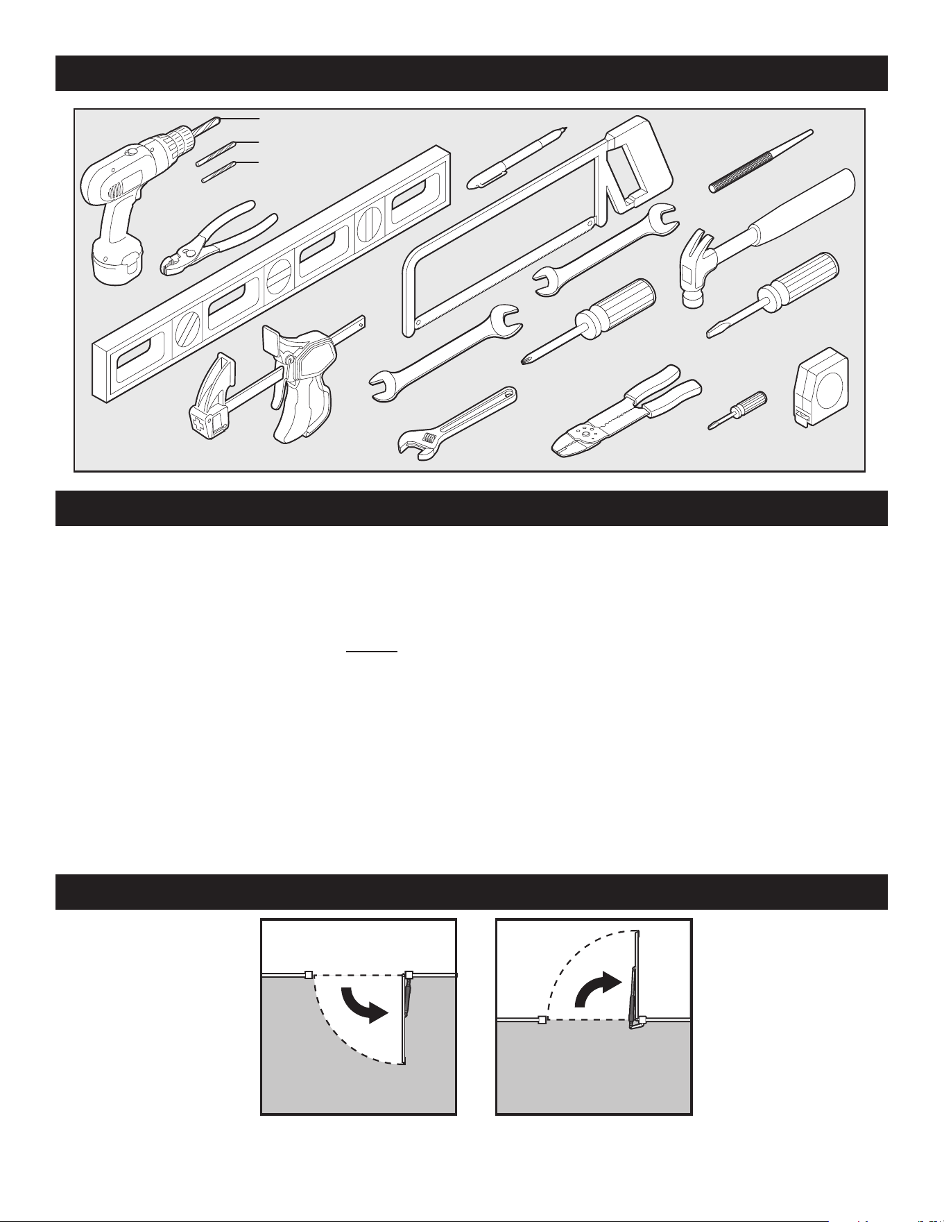
Tools Needed .................................................................................................................................................................................14
Items Not Included .........................................................................................................................................................................14
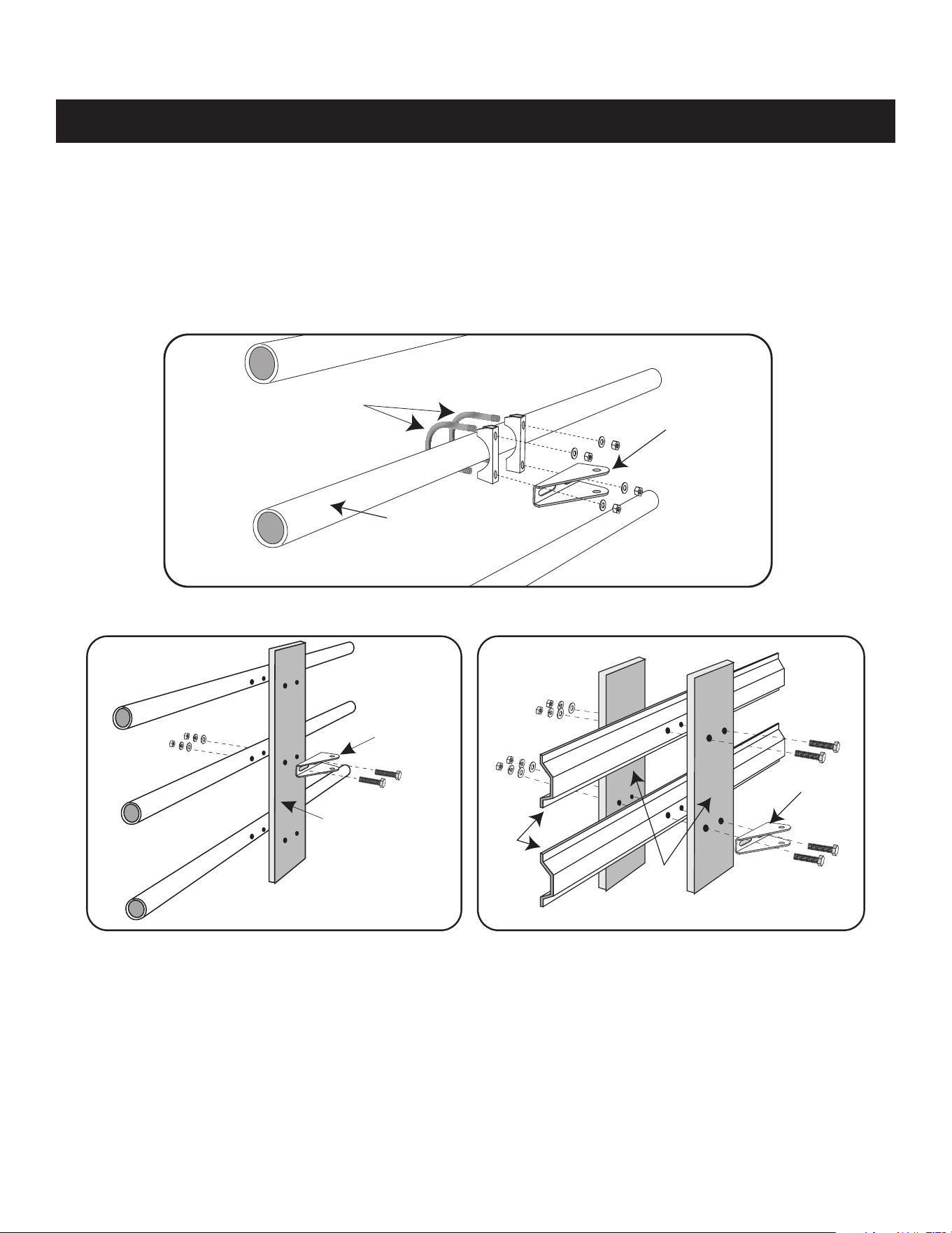
Check Direction of Gate Swing .......................................................................................................................................................14
Mechanical Installation ........................................................................................................................ 15
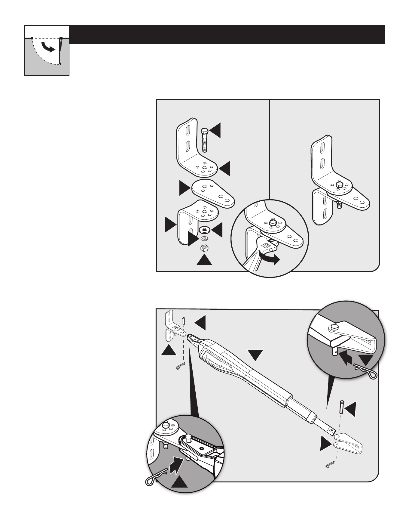
Assessing the Gate for Installation .................................................................................................................................................15
Pull-to-Open Operator Mounting
(
Most Common
) ...........................................................................................................................16
Installing the Closed Position Stop Plate / Pull-to-Open ...................................................................................................................21
Push-to-Open Operator Mounting ...................................................................................................................................................24
Installing the Closed Position Stop Plate / Push-to-Open .................................................................................................................29
Control Box Installation ...................................................................................................................................................................30
Connecting the Operator(s) and battery .........................................................................................................................................32
Connecting the Operator(s) and battery .........................................................................................................................................33
Transformer or Solar panel wiring Installation .................................................................................................................................34
Transformer or Solar panel wiring Installation .................................................................................................................................35
Electrical Installation and Setup .......................................................................................................... 37
Dip Switches settings .....................................................................................................................................................................37
Transmitter Programming ...............................................................................................................................................................38
Closed Limit Programming - Pull to Open .......................................................................................................................................39
Closed Limit Programming - Push to Open .....................................................................................................................................41
Dual Sense Stall Force Setting ........................................................................................................................................................43
Auto Close Setting ..........................................................................................................................................................................44
Optional Smart Control Setup .............................................................................................................. 44
Connecting Additional Devices ........................................................................................................... 45
Control Board Connections .............................................................................................................................................................46
Connecting Accessories .................................................................................................................................................................47
Maintenance ......................................................................................................................................... 48
Troubleshooting Guide - Audible Feedback ....................................................................................... 49
Troubleshooting Guide - Visual Feedback .......................................................................................... 51
Repair Service ...................................................................................................................................... 53
Accessories .......................................................................................................................................... 54
Appendix A ........................................................................................................................................ 56
Accessory Installation Instructions ..................................................................................................................................................56
Gate Operator Installation Checklist ................................................................................................... 57
MM571W / MM572W Installation Instructions
2
BEFORE YOU BEGIN TO INSTALL YOUR AUTOMATIC GATE OPERATOR:
Read these instructions carefully to become familiar with all parts and installation steps.
The video is only designed as an overview of the installation procedure.
You must read the installation manual for detailed instructions
on gate operator safety and proper use of the gate operator.
Please Read This First!
Thank you for purchasing a Mighty Mule Gate Operator—
Nortek Security & Control's "do-it-yourself" automatic
gate operator! When correctly installed and properly used,
your Mighty Mule Gate Operator will give you many years
of reliable service. Please read the following information
to ensure you have the correct system for your particular
needs. If so, this manual and will enable you to properly
install your Mighty Mule Gate Operator.
The Mighty Mule Gate Operator is designed for installation
for single or dual gates. The gate(s) must not exceed 18
feet in length or weigh more than 850 pounds (please see
Technical Specications on page 10). The Mighty Mule
Gate Operator can be used on vinyl, aluminum, chain link,
farm tube, and wrought iron gates.
Not rated for use on solid surface gates due to the
potential to damage the operator and/or injure someone.
The Mighty Mule Gate Operator accommodates extra
transmitters, digital keypads, solar panels, push buttons,
automatic gate locks, and other access control products.
These optional accessories (see the Mighty Mule
Accessory Catalog) are available at most stores. Your
store should be able to special order any accessory not in
stock.
If your store cannot special order accessories, please call
the Mighty Mule Sales Department (800-421-1587).
The Mighty Mule Gate Operator features Dual Sense
Technology™. This feature makes the gate stop and
reverse direction when it comes in contact with an
obstruction.
The Mighty Mule Gate Operator also has an adjustable
auto-close feature. After the gate reaches the fully open
position, it can be set to remain open up to 120 seconds
before automatically closing. Pressing the transmitter
button at any time after the gate opens fully will cause it
to close immediately. OFF is the factory setting; meaning
the gate will stay open until you press the transmitter (or
keypad, etc.) again.
Go to www.linearproaccess.com for a dealer or retailer
near you or call 800-421-1587 for information about our
Linear professional line of gate operators and accessories.
Our Sales Department will be glad to give you the name
and phone number of a Linear dealer near you.
NOT FOR THE CONTAINMENT OF ANIMALS.
MM571W / MM572W Installation Instructions
3
CAUTION
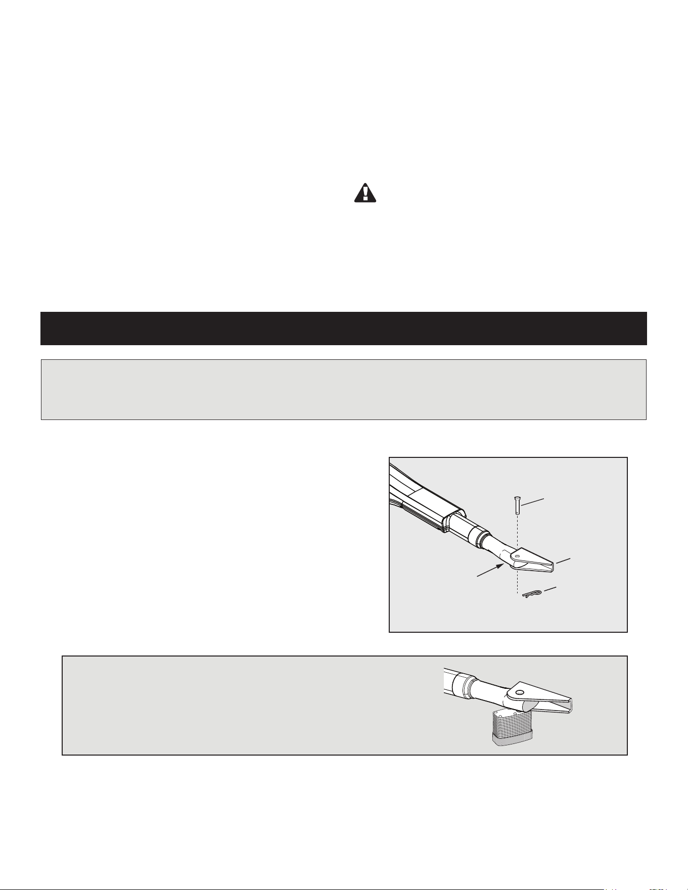
The gate will move freely and uncontrolled when the gate operator is removed from the gate.
ONLY disconnect the operator when the control box power switch is OFF and the gate is NOT moving.
Clevis Pin
Hairpin Clip
Gate Bracket
Front Mount
Because automatic gate operators produce high levels
of force, consumers need to know the potential hazards
associated with improperly designed, installed, and
maintained automated gate operator systems. Keep in
mind that the gate operator is just one component of
the total gate operating system. Each component must
work in unison to provide the end user with convenience,
security, and safety.
This manual contains various safety precautions and
warnings for the installer and end user. Because there
are many possible applications of the gate operator,
the safety precautions and warnings contained in this
Disconnecting the Operator
1. Turn control box power switch OFF.
2. Remove the hairpin clip and clevis pin.
3. Remove the operator’s front mount from the gate bracket.
The gate can be opened and closed manually when the operator
is disconnected.
manual cannot be completely exhaustive in nature. It
does, however, provide an overview of the safe design,
installation, and use of this product. CAREFULLY READ
AND FOLLOW ALL SAFETY PRECAUTIONS, WARNINGS,
AND INSTALLATION INSTRUCTIONS TO ENSURE THE
SAFE SYSTEM DESIGN, INSTALLATION, AND USE OF THIS
PRODUCT.
Warnings in this manual are identied with this
warning symbol. The symbol identies conditions that
can result in damage to the operator or its components,
serious injury, or death.
MANUALLY OPENING AND CLOSING GATE
Because Mighty Mule automatic gate operators are only part of the total gate operating system, it is the
responsibility of the installer and end user to ensure that the total system is safe for its intended use.
NOTE: Substitute a Pin Lock for the clevis pin on the front mount of
the gate operator to prevent theft of the operator from the gate (see
accessory pages in back of this book).
Important Safety Information
Part #: FM133
MM571W / MM572W Installation Instructions
4
WARNING
I. Before Installation
1. Verify this operator is proper for the type and size of gate, frequency of use
and class of the gate system.
2. Make sure the gate has been properly installed and swings freely in both
directions. Repair or replace all worn or damaged gate hardware prior to
installation. A freely moving gate will require less force to operate and will
enhance the performance of the entrapment protection devices used with
the system (see page 7).
3. Review the operation of the system to become familiar with its safety
features. Understand how to disconnect the operator for manual gate
operation (see previous page).
4. The gate and operator installation must comply with any applicable local
codes.
5. This gate operator is intended for vehicular gates only. A separate entrance
or gate must be installed for pedestrian use (see page 8).
6. Always keep people and objects away from the gate and its area of travel.
No one should cross the path of a moving gate.
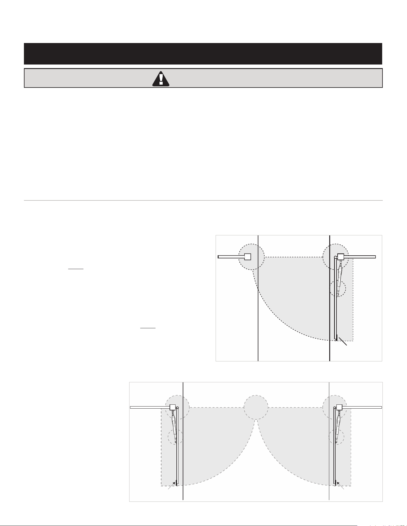
7. Identify all of the entrapment zones for the type of installation. An
entrapment zone is an area around the automatic gate system where
a person or object could be caught that increase the risk of injury.
Entrapment zones should be eliminated, guarded or protected.
8. When designing a system that will be entered from a highway or main
thoroughfare, make sure the gate system is placed far enough from the
road to prevent trafc congestion.
FOR THE INSTALLER AND END USER
Gate in the
Open Position
ZONE 2
ZONE 3
ZONE 4
ZONE 5
Driveway
ZONE 1
Entrapment
Zones for a
Pull-To-Open
Application
MM571W
Gate in the
Open Position
Gate in the
Open Position
ZONE 2
ZONE 3
ZONE 4
ZONE 5
Driveway
MM572W
ZONE 1
ZONE 2
ZONE 4
ZONE 5
ZONE 3
Entrapment Zones
for a Pull-To-Open
Application
1. READ AND FOLLOW ALL INSTRUCTIONS.
2. Never let children operate or play with gate controls. Keep the remote control
away from children.
3. Always keep people and objects away from the gate. NO ONE SHOULD CROSS
THE PATH OF THE MOVING GATE.
4. Test the gate operator monthly. The gate MUST reverse on contact with a
rigid object or stop when an object activates the non-contact sensors. After
adjusting the force or the limit of travel, retest the gate operator. Failure to
adjust and retest the gate operator properly can increase the risk of injury or
death.
5. Use the manual/emergency release only when the gate is not moving.
6. KEEP GATES PROPERLY MAINTAINED. Read the user’s manual. Have
a qualied service person make repairs to gate hardware.
7. The entrance is for vehicles only. Pedestrians must use separate
entrance.
8. The gate must be installed in a location that provides adequate
clearance between it and adjacent structures when opening and
closing to reduce the risk of entrapment. Swinging gates must not
open into public access areas.
9. SAVE THESE INSTRUCTIONS.
To reduce the risk of injury or death:
Important Safety Information
MM571W / MM572W Installation Instructions
5
II. During Installation
1. Install the gate operator on the inside of the property and
fence line. DO NOT install an operator on the outside of
the gate where the public has access to it.
2. Be careful with moving parts and avoid close proximity to
areas where ngers or hands could be pinched.
3. Devices such as contact sensors (sensing
edges) and non contact sensors (photo beams) provide
additional protection against vehicular damage.
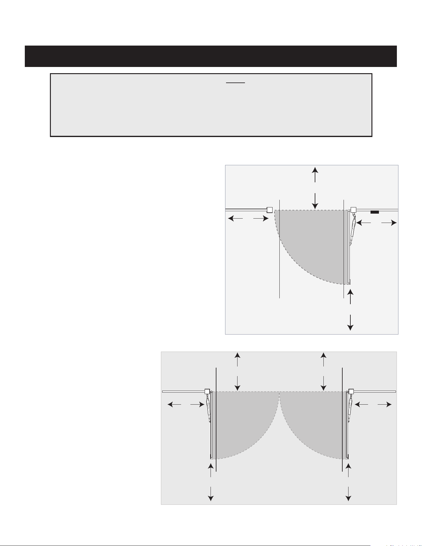
4. If push buttons or key switches are installed, they should
be within sight of the gate, located at least 10 feet from
any moving part of the gate (see diagram below).
Never install any control device where a user will
be tempted to reach through the gate to activate the
gate operator.
5. Secure outdoor or easily accessed gate operator controls
in order to prohibit unauthorized use of the gate.
FOR THE INSTALLER AND END USER
Typical Entrapment Zones are shown in the diagrams on page 7:
Zone 1 – leading edge of the gate and the fence post.
Zone 2 – between the gate and the gate post.
Zone 3 – the path of the gate.
Zone 4 – the space between the gate in the open position and any object such as a wall, fence, tree, etc.
Zone 5 – pinch points between the operator and gate.
Moving Gate
Area
Driveway
10'
10'
10'
10'
NEVER install any control device
within the indicated area
MM571W
Pull-To-Open Application
Important Safety Information
Pull-To-Open
Application
Moving Gate
Area
Moving Gate
Area
Driveway
10'10'
10'10'
10'10'
NEVER INSTALL
any control device
within the indicated area
MM572W
Pull-To-Open Application

MM571W / MM572W Installation Instructions
6
III. After Installation
1. Attach the warning signs (included) to each side of the
gate to alert the public of automatic gate operation. It is
your responsibility to post warning signs on both sides
of your gate. If any of these signs or warning decals
becomes damaged,
illegible, or missing, replace them immediately.
Contact Nortek Security & Control for free replacements.
2. The gate is automatic and could move at any time,
posing serious risk of entrapment. No one should be in
contact with the gate when it is
moving or stationary.
3. Do not attempt to drive into the gate area while the gate
is moving; wait until the gate comes to a complete stop.
4. Do not attempt to “beat the gate” while the gate is
closing. This is extremely dangerous.
5. Do not allow children or pets near your gate. Never let
children operate or play with gate controls. Keep the
remote control away from children and unauthorized
users; store controls where children and unauthorized
users do not have access to them.
6. KEEP GATE SYSTEMS MAINTAINED. Always turn power
to operator OFF before performing any maintenance. See
page 48 for maintenance procedures.
7. To operate this equipment safely, YOU must know how to
disconnect the operator for manual gate operation (see
page 17). If you have read the instructions and still do not
understand how to disconnect the operator, contact the
Mighty Mule Service Department.
8. Disconnect the operator ONLY when the power is
TURNED OFF and the gate is NOT moving.
9. Make arrangements with local re and law
enforcement for emergency access.
10. Distribute and discuss copies of the
IMPORTANT SAFETY INFORMATION
section of this manual with all persons
authorized to use your gate.
11. IMPORTANT: Save these safety instructions. Make sure
everyone who is using or will be around the gate and
gate operator are aware of the dangers associated
with automated gate systems. In the event you sell the
property with the gate operator or sell the gate operator,
provide a copy of these safety instructions to the new
owner.
Should you need a replacement manual, a copy can
be obtained by downloading one from the Mighty
Mule web site (www.mightymule.com), by contacting
Nortek Security & Control by calling 800-543-1236 and
requesting a duplicate copy.
FOR THE INSTALLER AND END USER
Important Safety Information
MM571W / MM572W Installation Instructions
7
FOR THE INSTALLER AND END USER
Mighty Mule gate operators utilize Dual Sense Technology™
entrapment protection. Dual Sense Technology
™ is built
into every Mighty Mule and provides redundant methods of
entrapment protection for open and close gate directions.
In addition to Dual Sense Technology, every Mighty Mule
gate controller has provisions for the connection of additional
obstruction detection devices such as sensing edges and
photo beams.
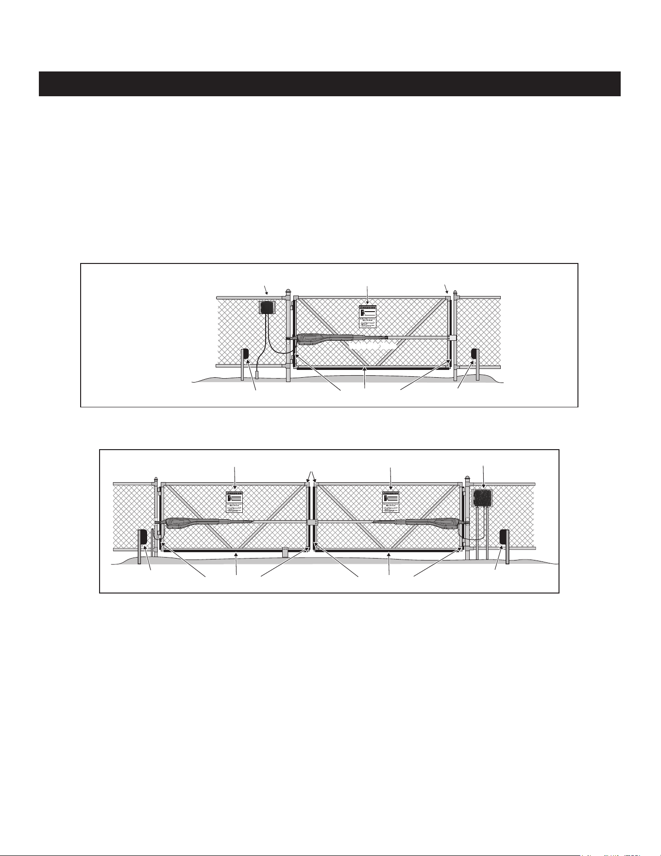
These devices may be located where there is an increased
risk of obstruction. Refer to the diagram below. One or more
edge sensors may be located at the leading edge, bottom
edge, and post edge, both inside and outside of a vehicular
swing gate system.
Wiring to sensors must be located and arranged so the wiring
between the sensor and the gate operator is not subjected to
mechanical damage.
A wireless sensor such as one that transmits radio frequency
(RF) signals that promote safety shall be located where the
transmission of the signals is not obstructed or impeded by
building structures, natural landscaping or similar objects.
Vehicular Gate
Vehicular Gate
Vehicular Gate
Vehicular Gate
Photo Beams
(recommended, not included)
Photo Beams
(recommended, not included)
Sensing Edges
(recommended, not included)
Sensing Edges
(recommended, not included)
Leading Edges
of gates
Gate Warning Sign
Gate Warning Sign Control Box
Leading Edge
of the gate
Photo Beam
(recommended, not included)
Photo Beam
(recommended, not included)
Sensing Edges
(recommended, not included)
Vehicular Gate
Gate Warning Sign
Control Box
Entrapment and Obstruction Protection
Mighty Mules’s Dual Sense Technology™ provides entrapment protection. Since all installations are different, you may need to
add photo beams or sensing edges to help prevent damage to vehicle or other items that could be hit by a moving gate.
Entrapment Alarm
The Mighty Mule Automatic Gate Operator is designed to stop and reverse the gate when the gate comes in contact with an
obstruction. Additionally, these operators are equipped with an audio entrapment alarm which will activate if the unit obstructs
twice while opening or closing. This alarm will sound for a period of 5 minutes, or until the operator receives an intended signal
from a hard wired entry/exit source (e.g. push button control or keypad). Turning the power switch on the control box OFF and
back ON will also deactivate the alarm. Wireless controls such as transmitters and wireless keypads will not deactivate the alarm.
Important Safety Information
Example of MM572W Installation
(Installations vary slightly on different types of gates)
Example of MM571W Installation
(Installations vary slightly on different types of gates)
NOTE: Photo beams should
always be located on the
non-travel side of the gate.
Note: Photo Beams should always be located on the non-travel side of the gate.
MM571W / MM572W Installation Instructions
8
Bulldog Pedestrian
Gate Lock
(recommended, not included)
7 foot
minimum
Warning SignPedestrian Gate
Warning SignControl Box
Vehicular Gate
Vehicular Gate
Vehicular Gate
Vehicular Gate
Warning Sign
Pedestrian Gate
Pedestrian Gate Lock
(recommended, not included)
7 foot
minimum
Control Box
Vehicular Gate
Vehicular Gate
Important Safety Information
Warning signs alert people of automatic gate operation and are required when installing Mighty Mule Automatic Gate
Operators. A minimum of two WARNING SIGNS must be installed in the area of the gate. Each sign is to be visible by
persons located on the side of the gate on which the placard is installed.
The operator is intended for installation only on gates used for vehicles. Pedestrians must be supplied with a separate
access opening. The pedestrian access opening shall be designed to promote pedestrian usage. Locate the gate such
that persons will not come in contact with the vehicular gate during the entire path of travel of the vehicular gate.
We recommend using the Bulldog Pedestrian Gate Lock (Call the Nortek Security & Control Sales Department at 800-
421-1587) for controlled access.
INSTALLING WARNING SIGNS AND PEDESTRIAN GATES
Warning Signs
The gate operator is provided with two safety warning signs (four signs for dual operator
installation). The signs MUST be installed on the front and back of the gate where they will be
visible in the area of the gate.
Permanently secure each warning sign to the gate.
Immediately replace a damaged, eligible or missing warning sign.
Call Customer Service at 800-421-1587 for a free replacement.
!
Example of MM572W Installation
(Installations vary slightly on different types of gates)
Example of MM571W Installation
(Installations vary slightly on different types of gates)
MM571W / MM572W Installation Instructions
9
Labels (1) installed on the front of control box
10019674A
1. KEEP CLEAR! Gate may move at any time.
2. Read all SAFETY INSTRUCTIONS in the user’s manual.
3. Do not allow children to operate gate or play in gate area.
4. This gate is for vehicles only. Pedestrians must use separate entrance.
Moving gate can cause injury or death!
1. TENEZ-VOUS LOIN! La barrière peut se déplacer à tout moment.
2. Lisez toutes les instructions de sécurité dans le manuel de l'utilisateur.
3. Ne laissez pas les enfants utiliser la barrière ou jouer à proximité de la barrière.
4. Cette barrière est uniquement réservée aux véhicules. Les piétons doivent
utiliser une autre entrée.
AVERTISSEMENT
WARNING
La barrière en mouvement peut provoquer des
blessures graves ou la mort!
Important Safety Information
These warning labels should be found at the locations specied below. If any of them are missing, immediately contact
Nortek Security & Control for replacements.
REQUIRED SAFETY PRECAUTIONS FOR GATES

MM571W / MM572W Installation Instructions
10
Maximum Weight (lbs.) Maximum Length (ft.)
850 8
750 10
650 12
550 14
450 16
350 18
MIGHTY MULE 571W/572W GATE OPENER
Technical Specications
NOTE: Ball bearing hinges should be used on all gates weighing over 250 lb.
The Gate Capacity Chart below shows the recommended maximum gate length to weight. The minimum
recommended gate length is 5 ft.
_____________________________________
DRIVE
_____________________________________
• Low friction screw drive (linear actuator) rated for -5 °F to +160 °F (-20 °C to +71 °C).
• Powered by a 12 V motor with integral gear reducer. Motor speed reduced to 348 rpm at 12 V.
• Maximum opening arc of 110°. Approximate opening time (90°): 18 seconds, depending on weight of gate.
_____________________________________
POWER
_____________________________________
• The system is powered by a 12 Vdc battery (included). A second Mighty Mule battery may be used (not included).
• Battery charger is on the control board and maintained by a 120Vac to 19VDC output transformer or by
optional Solar Panels; the panel should generate minimum of 10 Watts (600 mA/20 watt max.). A diode on the
control board prevents battery discharge. IMPORTANT: Never use both transformer and solar panel— this will
damage the battery and control board.
• Three (3) Mini blade-style fuses rated for 25A.
• NOTE: The transformer should not be directly connected to any battery. Do not replace fuses with higher
ampere rated fuses; doing so will void your warranty and may damage your control board.
_____________________________________
CONTROL
_____________________________________
• Microprocessor-based control board is set for single or dual leaf, pull-to-open or push-to-open installations.
• Control board has temperature compensated circuits.
• Learn based digital transmitter technology provides millions of codes for enhanced security.
• Receiver is tuned to 318 MHz
• Opener length with push-pull tube fully retracted is 40 1/4", mounting point to mounting point.
Maximum stroke is 20".
• Adjustable auto-close timer (OFF to 3–120 seconds), and Dual Sense Technology™ stall force.
• Power terminal block accommodates a transformer or solar panels.
• Accessory terminal block fully compatible with all Mighty Mule access controls.
• Control board allows connection of edge sensors and photoelectric sensors.
• Audio entrapment alarm sounds if unit encounters an obstruction twice while opening or closing.
__________________________________
OPERATIONAL CAPACITY _________________________________
MM571W / MM572W Installation Instructions
11
1. Determine Charging Option for Battery: Transformer OR Solar
IMPORTANT:
● The transformer is designed for indoor use. If the transformer can be plugged only into an outside electrical outlet, a
weatherproof cover/housing (available at local electrical supply stores) must be used.
● If your gate is more than 1000 ft. from an AC power source, you will need to use at least 10 watt solar charging power to
charge the battery [FM123]. Refer to the Solar Panel and Gate Activity chart below.
● All low voltage wire used with the Mighty Mule gate operator must be 16 gauge dual conductor, stranded, direct burial
wire [RB509]. Do not run more than 1000 ft. of wire.
NEVER USE TRANSFORMER AND SOLAR PANEL(S) AT
THE SAME TIME. It will damage the control board.
The table and map
illustrate the maximum
number of gate cycles
to expect per day in a
particular area when
using from 10 to 30 watts
of solar charging power
prior to the battery depleting to a state where
the unit will not function. The gures shown
are for winter (minimum sunlight). Accessories
connected to your system will draw additional
power from the battery.
Accessories connected to your system will draw
additional power from the battery.
A second battery [FM150] is recommended for solar
and/or high trafc applications. See the accessory
catalog.
Before You Begin
POWERING OPTIONS
SOLAR PANEL AND GATE ACTIVITY CHART
Single Gate Winter Ratings Zone 1 Zone 2 Zone 3
12 v single gate (10 watts) solar charger 8 16 26
12 v single gate (20 watts) solar charger 14 28 38
12 v single gate (30 watts) solar charger 20 44 54
* Power increments are for reference only.
* If the gate operator controller is OFF, the system will NOT charge the battery.
MM571W / MM572W Installation Instructions
12
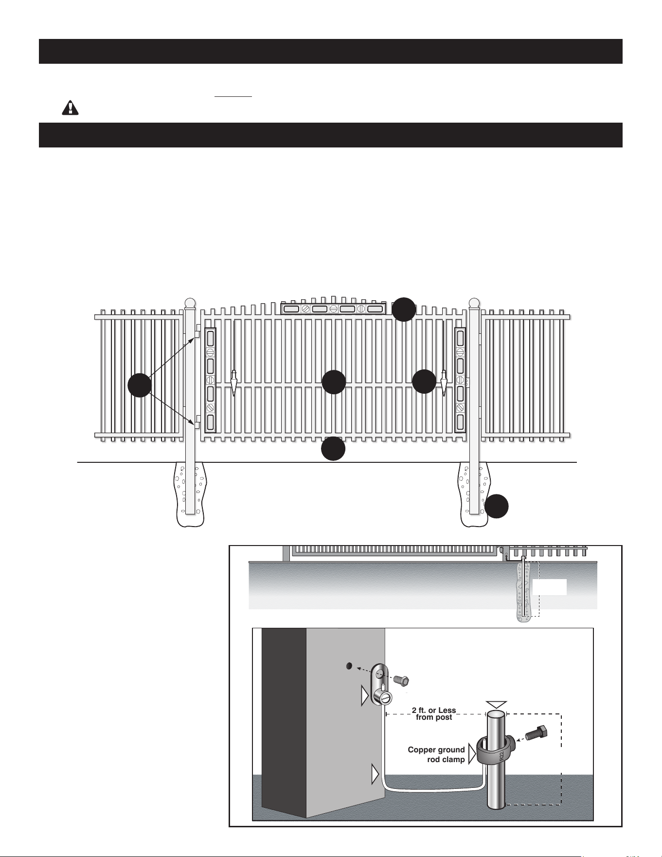
E
A
B
C
D
F
Gate Grounding
● For reference only.
Copper Clad Ground Rod
(not included)
Use an 8 foot, 5/8 inch ground rod,
positioned two feet or less from the
post and 2 inches or less above the
ground. Available at local home center
or hardware stores.
NOTE: No grounding system absolutely
protects against lightning strikes. If
installed correctly, a grounding system
will help minimize damage to your
gate operator.
● The gate must be plumb, level, and swing freely on its hinges.
● The gate must move throughout its arc without binding or dragging on the ground.
● Wheels must NOT be attached to the gate.
● Gates over 250 lb. should have ball bearing hinges with grease ttings.
● Post must be secured in the ground with concrete (minimizes twist/ex when the operator is activated).
● Make sure there is a stable area for mounting the gate bracket (this may require the addition of a horizontal or vertical cross
member).
● We recommend you position the operator near the center-line of a gate to keep the gate from twisting and exing, and to
avoid back-splash from rain.
Copper clad ground rod
(not included)
Ground
Ground
2 Inches or
Less above
ground
Copper ground
rod clamp
Copper Single
Conductor Lug
3/16” Drilled
Pilot Hole
6 ft. deep
or more
Metal gate post
Metal Gate Post
12awg or Larger
Gate Opener
Control Box
2 ft. or Less
from post
IMPORTANT: CHECK FOR PROPER GATE INSTALLATION
CHECK EXISTING GATE SIZE AND MATERIAL
• Gate size: Up to 18 feet and up to 850 lbs. — See
Operational Capacity chart on page 10.
Not rated for use on solid surface gates.
• Type of gate material: Vinyl, aluminum, chain link,
farm tube, wrought iron, wood.
A - Level
B
- Plumb
C
- Free Swinging
D
- Secured Posts in
Concrete
E - Center line Mounting
F - Good Working Hinges (ball bearing
hinges are recommended on gates
over 250 pounds)
MM571W / MM572W Installation Instructions
13
Battery Box, Control Box,
Antenna, Battery
& Battery Harness
Operator
Arm
Gate Bracket
Post Pivot Bracket
Post Brackets (2)
RP1010 Transformer
Literature kit
with gate
warning signs
Closed Position
Stop Plate
MMT 103
Transmitter
A
F
G
I
E
B
C
H
D
8” Nylon Cable Tie (10)
J
3/8” Washer (9)
5/16” Clipped Washer (1)
K
L
3/8” x 8” Bolt (4)
M
3/8” x 1-1/2” Clevis Pin (2)
2” Mounting Screw (4)
S
R
3/8” Nut (7)
5/16” Lock Nut (1)
U
T
5/16” x 1-1/2” Bolt (1)
Q
W
P
3/8” x 2-3/4” Bolt (2)
®
3/8” Lock Washer (7)
V
3/8” x 1-1/2” Bolt (1)
Hairpin Clip (2)
#10-14 x 3/4” Screw (8)
N
O
3/8” x 1-1/2” Clevis Pin (2)
3/8” x 8” Bolt (4)
8” Nylon Cable Tie (10)
Operator
Arm
Gate Bracket
Post Pivot Bracket
Post Brackets
Closed Position
Stop Plate
3/8” x 1-1/2” Bolt (1)
5/16” x 1-1/2” Bolt (1)
3/8” Washer (9)
5/16” Washer (1)
3/8” Nut (7) 5/16” Lock Nut (1)
Hairpin Clip (2)
2” Mounting Screw (4)
F
G
E
B
H
J K
N
L
Q
S
O
P
M
R
U
T
3/8” x 2-3/4” Bolt (2)
3/8” Lock Washer (7)
V
ITEMS INCLUDED FOR PRIMARY GATE OPENER INSTALLATION (MM571W)
ITEMS INCLUDED FOR SECONDARY OPENER INSTALLATION (MM572W)
MM571W / MM572W Installation Instructions
14
7/16” Bit
1/2” Bit
7/32” Bit
Drill
Pliers
Level
Clamps
Adjustable
Wrench
Pen
Center
Punch
Hammer
Tape
Measure
Small
Flat Head
Philips Head
Screwdriver
Flat Head
Screwdriver
Wire
Stripper
Hack Saw
1/2”
wrench
9/16”
wrench
● Low voltage wire will be needed to run from the
transformer to the control box; length depends
upon the distance between the transformer power
supply and the control box. You will need 16 gauge,
low voltage direct burial wire. See Transformer/
Solar Panel Wiring Installation on page 38 and the
accessory catalog.
● PVC conduit.
● If you have thin-walled tube or panel gates, see
Reinforcing Gates for the Gate Brackets, next page.
● Depending on the type of gate, a horizontal cross
member or mounting plate may be needed to
mount the front of the operator and gate bracket to
the gate. See the Reinforcing Gates for the Gate
Brackets examples, next page.
● Surge protection for transformer.
● Some types of installations require u-bolts.
● Additional washers or a metal plate may be
needed for wooden post.
● Weatherproof cover for outdoor outlet and
transformer.
● If the post is larger than 6”, bolts longer than 8”
are needed.
ITEMS NOT INCLUDED
TOOLS NEEDED
CHECK DIRECTION OF GATE SWING
Pull-to-Open Option
Instructions begin on page 2.
Push-to-Open Option
Instructions begin on page 8.
Your Property Your Property
Pull-To-Open
(arm retracts to open)
Push-To-Open
(arm extends to open)
(Requires Push-To-Open Bracket
#FM148—NOT INCLUDED)
MM571W / MM572W Installation Instructions
15
Mechanical Installation
ASSESSING THE GATE FOR INSTALLATION
Your gate operator can be mounted to a variety of gate types. This section shows some of the most common, along with the
reinforcement methods recommended prior to or while mounting your gate operator.
Reinforcing Gates for the Gate Brackets
We recommend using a mufer clamp, wood, or metal, to reinforce thin-walled tube gates, or wood to reinforce panel gates
as shown. These reinforcement methods will prevent damage to the opener and gate. Additional hardware may be needed
depending on the installation. Additional hardware necessary but not included.
Gate
Bracket
Panel
Gate
1" x 6"
Wood
Reinforcement
Gate Bracket
Wood or Metal
Reinforcement
(not supplied)
Thin Walled
Tube Gate
Gate Bracket
Muffler Clamp
(not supplied)
Mufer Clamp for Gate Bracket
Wood or Metal Reinforcement 1” x 6” Reinforcement
MM571W / MM572W Installation Instructions
16
S
E
S
F
B
N
N
!
G
L
O
F
G
V
T
S
F
B
S
E
N
!
G
L
O
F
G
T
Minimum 80˚ Open
N
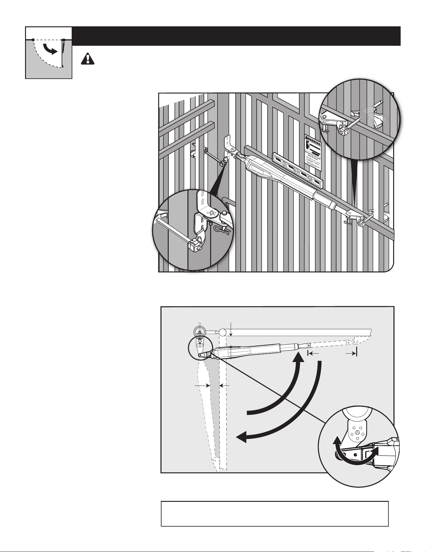
PULL-TO-OPEN OPERATOR MOUNTING
(
MOST COMMON
)
● Assemble the gate post bracket sub
assembly as displayed.
● Attach the gate post bracket
subassembly and gate bracket to the
operator as shown.
● The operator must be retracted with
the gate in the open position. Do not
spin out the inner cylinder
Step 1
Step 2
Your Property
MM571W / MM572W Installation Instructions
17
S
F
B
S
E
N
!
G
L
O
F
G
T
N
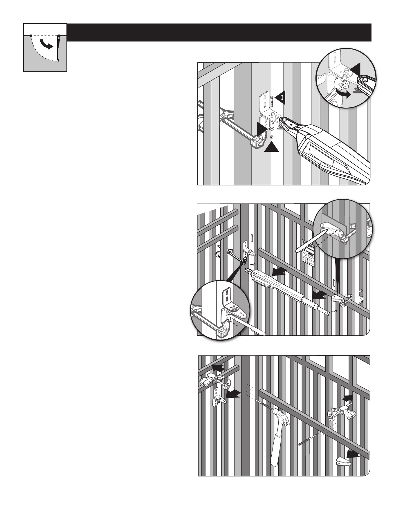
PULL-TO-OPEN OPERATOR MOUNTING
● Disconnect the operator arm from the
gate bracket.
● While supporting the operator, swing
the gate and operator to the closed
position.
● Check for recommended clearances
and binding as shown. Ensure the
rear mount of the operator does
not press up against the post pivot
bracket assembly in the closed
position as indicated in the diagram
to the right. Note the circled portion of
the diagram.
● Ensure that the necessary arm /
stroke does not exceed 20 inches.
● Make adjustments to the
mounting brackets to achieve the
recommended clearances. Improper
clearance will cause undue stress on
the operator and may cause physical
damage and/or strain the motor.
TIP: Turning the pivot bracket over
gives more hole alignment options for
the gate post pivot bracket assembly.
● With the gate in the OPEN position,
use clamps to secure the operator
to the gate post and center cross
member of the gate.
● Ensure that the operator is level.
● With the operator arm temporarily
secured to the gate, check to
ensure there is at least 2 inches
of clearance between the operator
arm and gate. (See illustration in
Step 4 below).
2" Min. - Pinch-Point Clearance
Top View
2" Min.
20" MAX.
2
1
Closed
Position
Open
Position
Step 3
Step 4
Your Property
THE OPERATOR MUST BE INSTALLED WHILE FULLY RETRACTED, WITH THE GATE IN THE OPEN POSITION.
WARNING: ENSURE THE REAR MOUNT DOES NOT MAKE CONTACT WITH THE
POST-BRACKET ASSEMBLY DURING ANY POINT OF THE GATE TRAVEL.
MM571W / MM572W Installation Instructions
18
M
L
T
V
Q
K
U
O
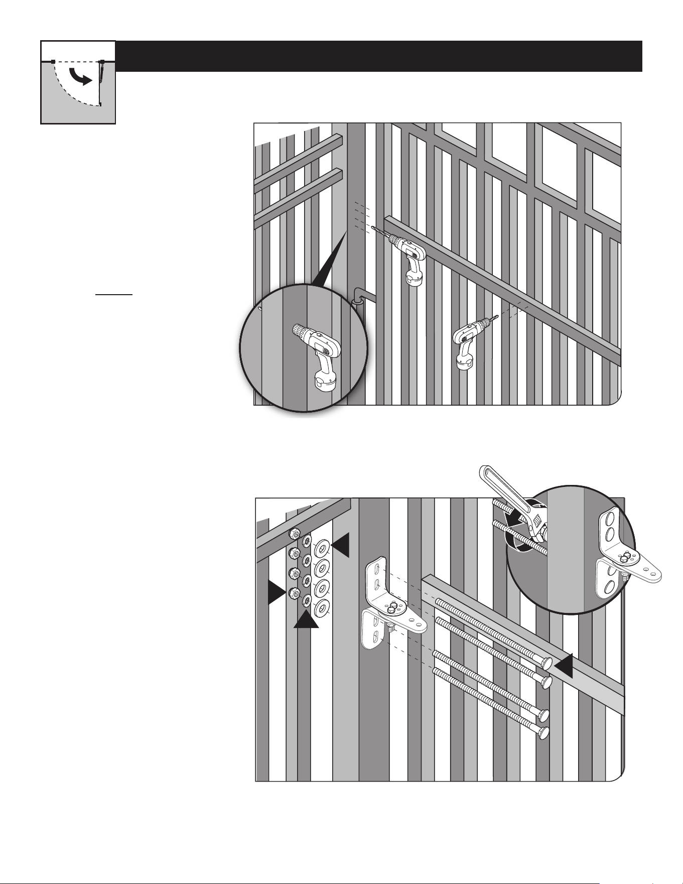
● Using a permanent marker, mark the center of
the mounting locations for the gate post bracket
subassembly.
● Remove the operator arm from the gate post and
gate brackets.
● Mark the center of the mounting locations for the
gate bracket.
● Open the gate and reattach the operator to the gate
bracket.
● Ensure that the operator arm is level and the
brackets are securely clamped.
● Secure the post pivot bracket in place by installing
the hardware shown. Tighten both bolts (O and Q).
● Remove the gate post and gate brackets.
● Use a hammer and center punch to mark the center of
the mounting locations.
Step 6
Step 5
Step 7
PULL-TO-OPEN OPERATOR MOUNTING
Your Property
MM571W / MM572W Installation Instructions
19
M
L
T
V
M
L
T
V
Step 8
Step 9
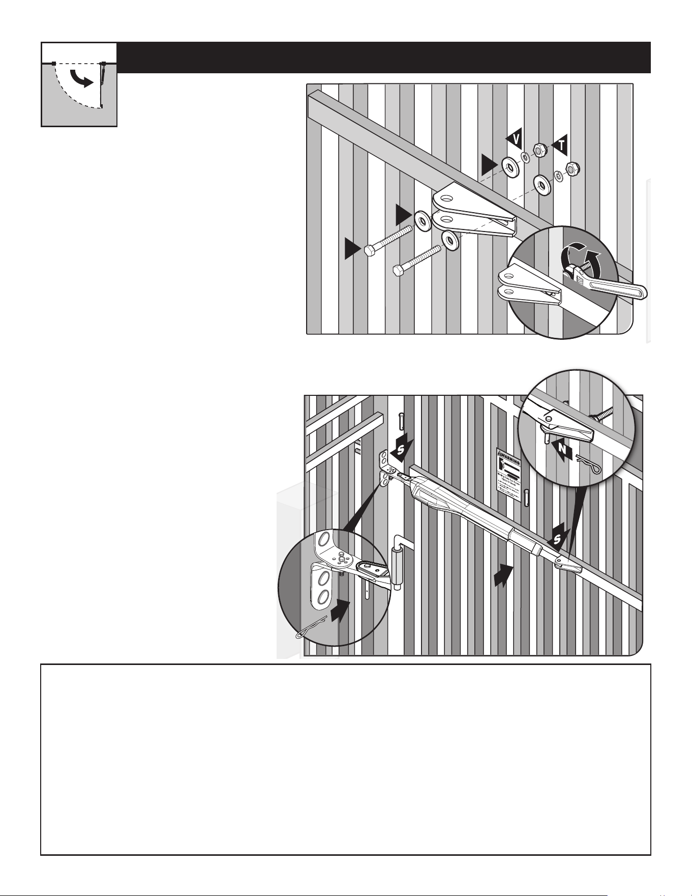
PULL-TO-OPEN OPERATOR MOUNTING
● Using a drill and 7/16” drill bit,
drill the necessary holes to mount
the gate post and gate brackets.
Note: Some installations may
require additional reinforcement
be installed on the gate.
See page 17.
● Secure the gate post bracket
subassembly with the supplied
hardware as shown.
Your Property
MM571W / MM572W Installation Instructions
20
T
L
L
V
P
S
S
N
N
T
L
L
V
P
N
S
S
N
● Secure the gate bracket with the supplied
hardware as shown.
● Once the gate post and gate brackets are
installed, reattached the operator arm.
● Ensure the operator arm is level, adjusting
the post bracket location if necessary.
● Once level, ensure all hardware is tight.
● Remove excess bolt length with a hacksaw.
Step 10
Step 11
PULL-TO-OPEN OPERATOR MOUNTING
Your Property
Installing the Secondary Operator (MM572W only):
Note: The Primary arm must be installed on the side near the control box.
Install the secondary operator on the remaining leaf by repeating the same process illustrated in steps 1-11 above.
Note: You will need to run the secondary operator power cable and any hard wired accessory wires under the driveway to the
control box (use of conduit is recommended).
Installing the Control Box:
Locating the control box on the gate leaf closest to the power source or desired solar panel location is recommended. The
primary operator arm must be located on the gate leaf next to the control box.
See front page of this manual for a complete installation example. After you have mounted the second operator, proceed to
Installation of the Closed Position Stop Plate on the following pages.
MM571W / MM572W Installation Instructions
21
H
1
2
1
Fence Post: MM571W
Leading Edge of
Second Gate: MM572W
H
1
2
1
Fence Post: MM571W
Leading Edge of
Second Gate: MM572W
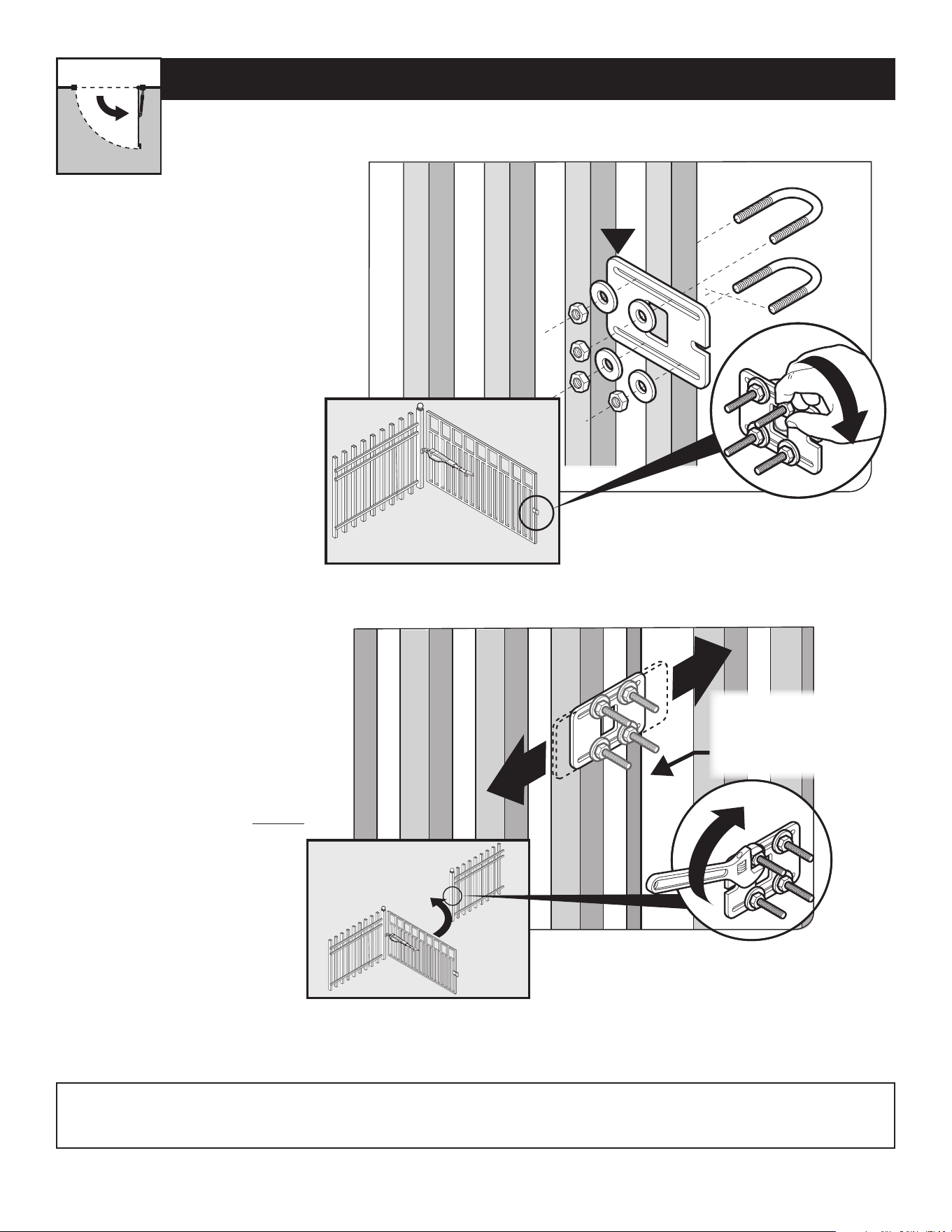
● Remove the operator from the
gate post and gate brackets.
● With the gate fully open, install
the closed position stop plate
(hardware not included).
● Do not fully tighten hardware
until after the next step.
● Swing the gate to the closed
position, and adjust the closed
position stop plate against the
fence post.
● Tighten the mounting hardware.
● Return the gate to the open
position and reinstall the operator
arm.
● To complete the pull-to-open
installation, proceed to page 16.
INSTALLING THE CLOSED POSITION STOP PLATE / PULL-TO-OPEN
Step 1
Step 2
Your Property
Note: For MM572W installations, the closed position stop plate should be installed on the leading edge of the PRIMARY gate
leaf, and adjusted to close against the leading edge of the SECONDARY gate leaf.
MM571W / MM572W Installation Instructions
22
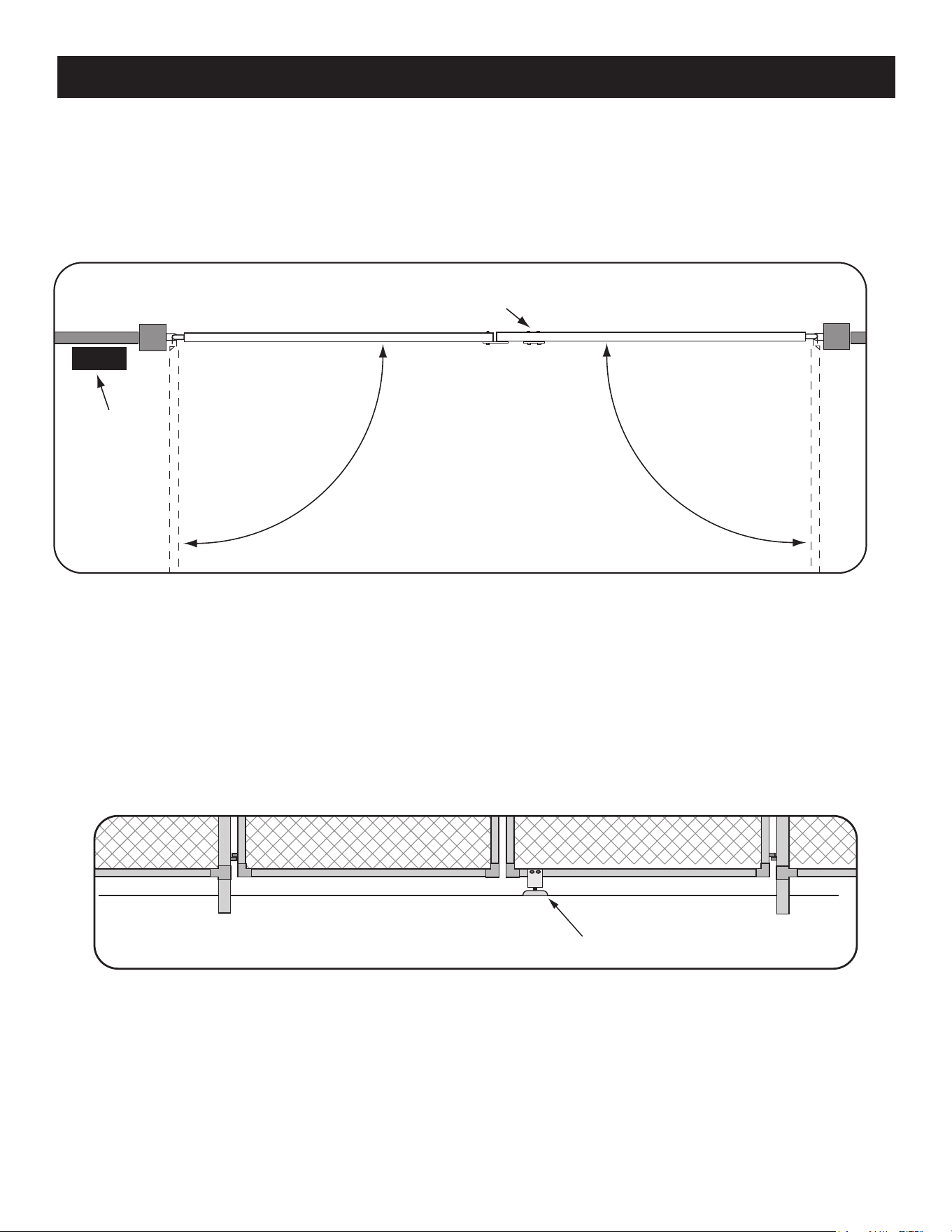
An optional low prole ground stop, when used with the closed position stop plate, provides a secure point for the SECOND
gate to close against.
To further enhance the stability and security of your gate, install a Mighty Mule Automatic Gate Lock [FM143]. If you will be
using the Mighty Mule Gate Lock with your gate opener system, the closed position ground stop is required.
For Pull-to-Open systems, install the Ground Stop Plates on the inside of the gates.
For Push-to-Open systems, install the Ground Stop Plates on the outside of the gates.
Step 1
Detach the gate opener arms from the gates and move the gates to the closed position.
Step 2
The low prole ground stop may be made of metal or concrete and should be rmly secured in the ground. The low prole
ground stop should be installed beneath the SECOND gate, positioned near the leading edge.
CONTROL BOX
Optional Ground Stop
(beneath gate)
FIRST GATE SECOND GATE
Low Profile Ground Stop
(not included)
Post Bracket Assembly
Gate Bracket
INSTALL THE GROUND STOP PLATE
MM571W / MM572W Installation Instructions
23
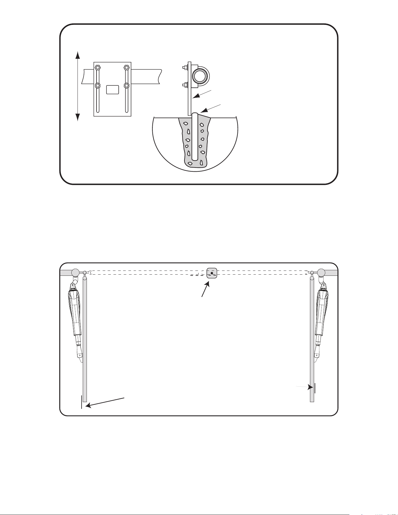
Closed Position Stop Plate mounted
on the SECOND GATE
• •• • • • •• • • •• •• • •• • • • •• •• • •
• • • •• • • • ••• Ground Stop
•• •• • • ••• • • •• • • • • • •• ••• ••• • • • •
FACING VIEW
SIDE VIEW
• •• • ••• ••••• • •••
Closed Position
Stop Plate
Low Prole Ground Stop
Closed Position
Stop Plate
Step 3
Using appropriate hardware for your type of gate, attach the vertical closed position stop plate to the SECOND gate frame at the
point where it will come in contact with the low prole ground stop. Do not tighten it completely at this time. You must slide the
closed position stop plate toward the low prole ground stop until they touch. Once you have moved the stop plate to the correct
position, tighten its hardware completely.
Step 4
Return the gates to their open positions and reattach the gate openers to the gates.
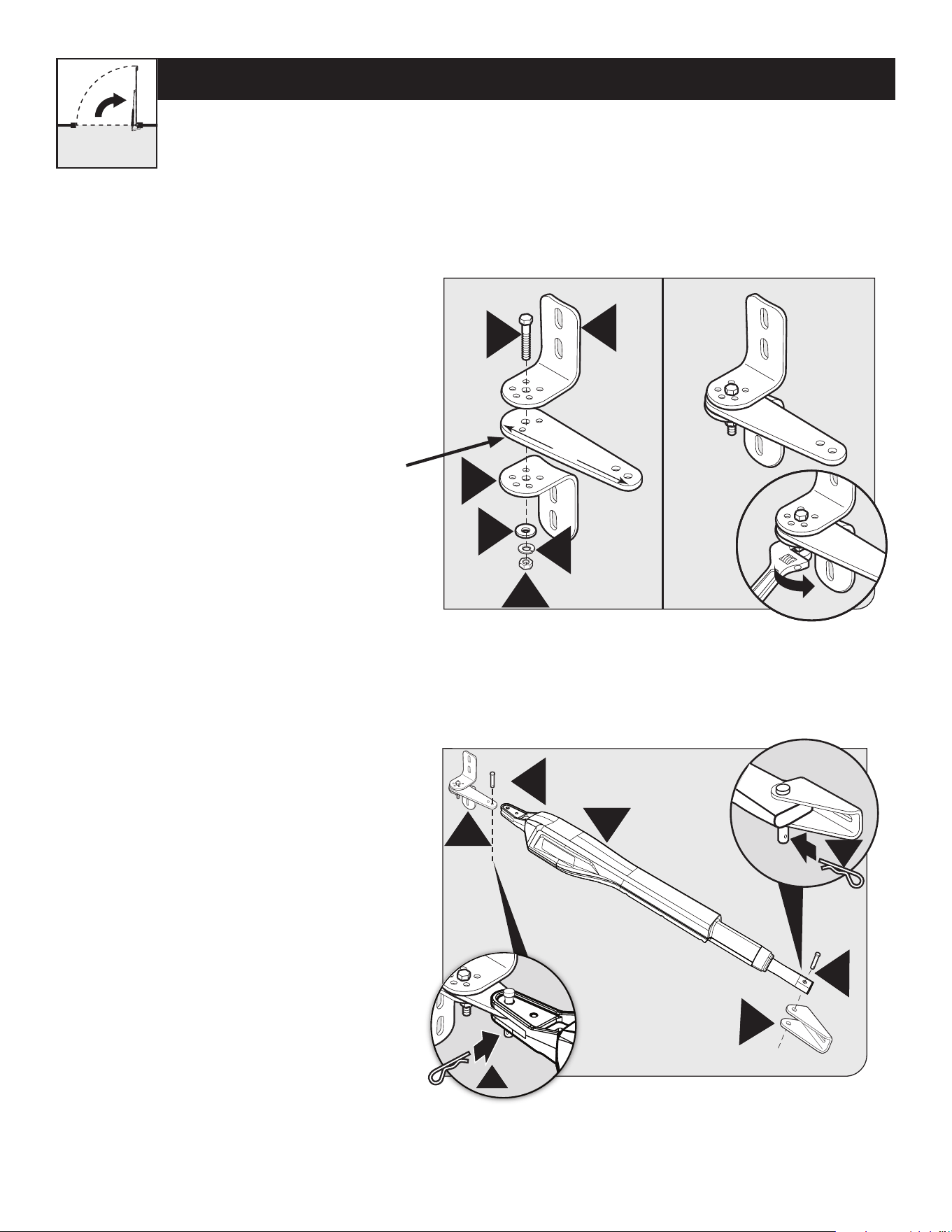
MM571W / MM572W Installation Instructions
24
PUSH-TO-OPEN OPERATOR MOUNTING
G
V
T
O
L
G
11”
S
S
E
F
B
N
N
G
V
T
O
L
G
11”
S
S
E
F
B
N
N
Step 1
Step 2
● Assemble the gate post bracket subassembly
as shown with the Push-to-Open pivot bracket
(FM148). Must be purchased separately.
● Attach the gate post bracket subassembly and
gate bracket to the operator as shown.
● The operator must be retracted with the gate in the
closed position. Do not spin out the inner cylinder.
Your Property
Push-to-Open pivot
bracket (FM148)
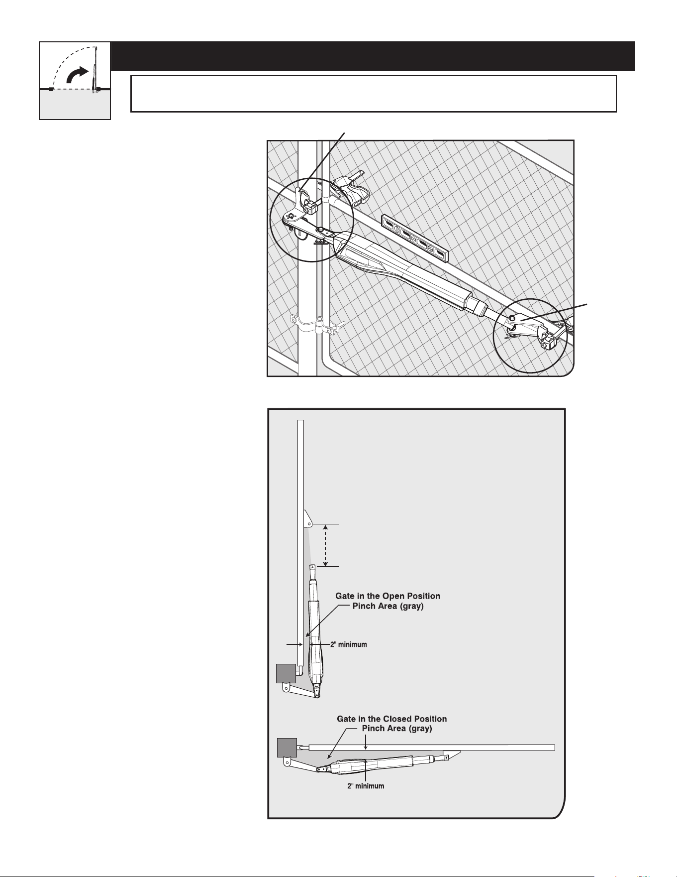
MM571W / MM572W Installation Instructions
25
PUSH-TO-OPEN OPERATOR MOUNTING
L
e
v
e
l
horizontal
cros
s
me
m
be
r
L
ev
e
l op
e
ner
Gate in Closed Position
Gate Bracket
Post Bracket Assembly
Step 3
Step 4
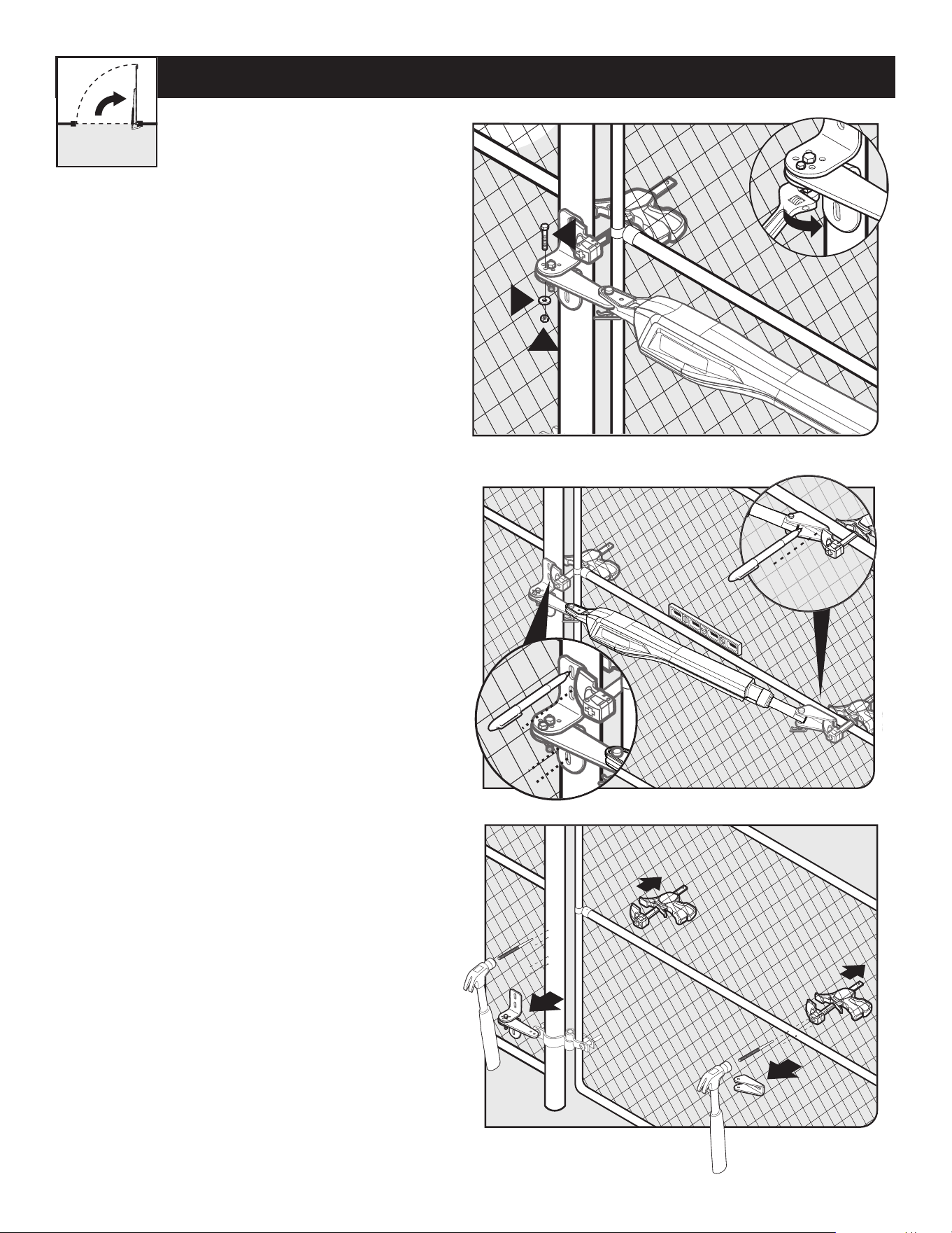
● With the gate in the CLOSED
position, use clamps to secure the
operator to the gate post and center
cross member of the gate.
● Ensure that the operator is level.
● With the operator arm temporarily
secured to the gate, check to
ensure there is at least 2 inches of
clearance between the operator arm
and gate. (See illustration in Step 4
below).
20” MAX
CLEARANCE DIAGRAM
● Disconnect the operator arm from the
gate bracket.
● While supporting the operator, swing
the gate and operator to the OPEN
position.
● Check for recommended clearances
and binding as shown.
● Ensure that the necessary arm stroke
does not exceed 20 inches.
● Make adjustments to the mounting
brackets to achieve the recommended
clearances.
TIP: Turning the pivot bracket over
gives more hole alignment options for
the gate post pivot bracket assembly.
Your Property
WARNING: THE OPERATOR MUST BE INSTALLED WHILE FULLY RETRACTED, WITH THE GATE IN THE
CLOSED POSITION.
MM571W / MM572W Installation Instructions
26
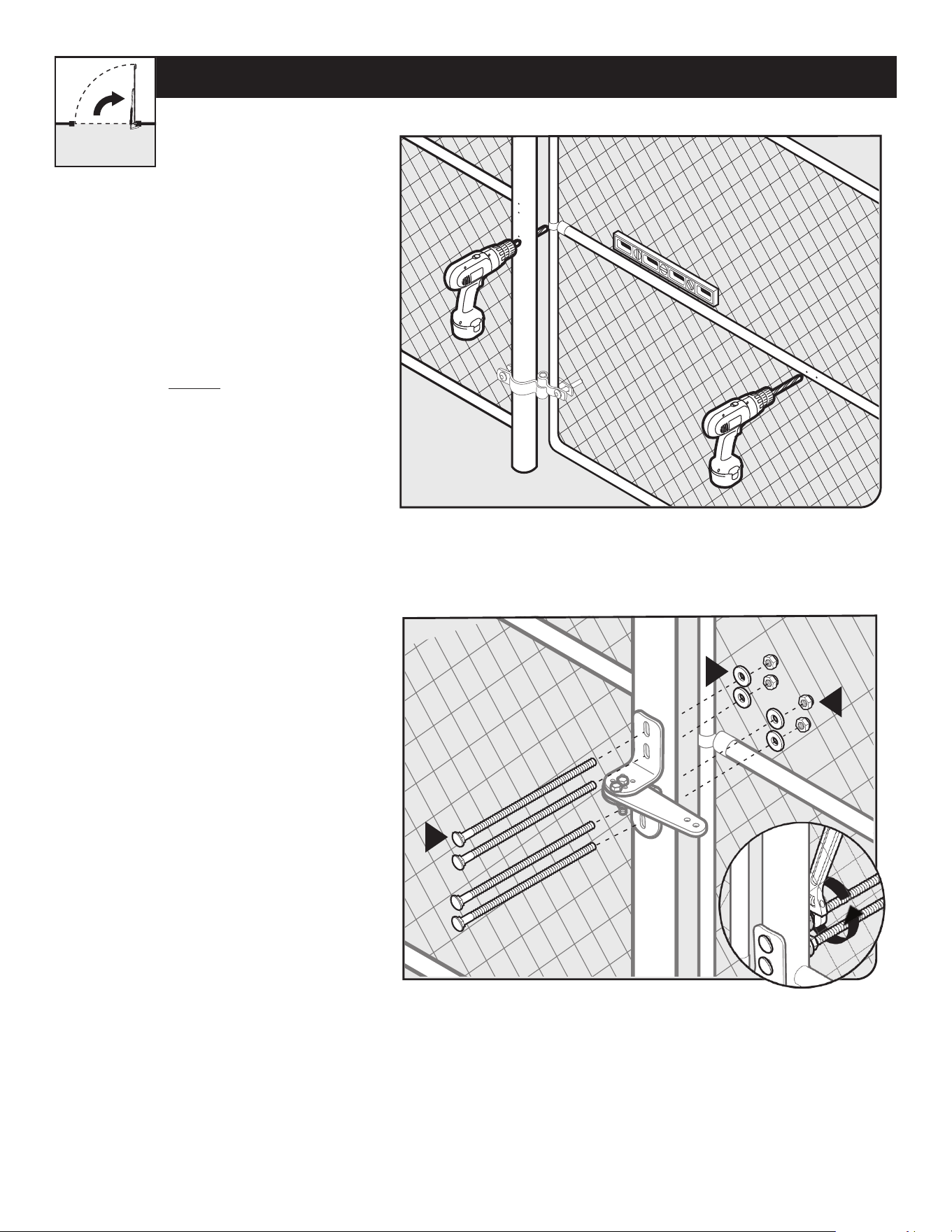
● Remove the gate post and gate brackets.
● Use a hammer and center punch to mark the
center of the mounting locations.
● Using a permanent marker, mark the center of
the mounting locations for the gate post bracket
subassembly.
● Remove the operator arm from the gate post and
gate brackets.
● Mark the center of the mounting locations for the
gate bracket.
PUSH-TO-OPEN OPERATOR MOUNTING
Step 6
Step 5
Step 7
Q
K
U
● Close the gate and reattach the operator to the
gate bracket.
● Ensure that the operator arm is level and the
brackets are securely clamped.
● Secure the post pivot bracket in place by
installing the hardware shown. Tighten both bolts
‘O’ and ‘Q’.
Your Property
MM571W / MM572W Installation Instructions
27
PUSH-TO-OPEN OPERATOR MOUNTING
Step 8
Step 9
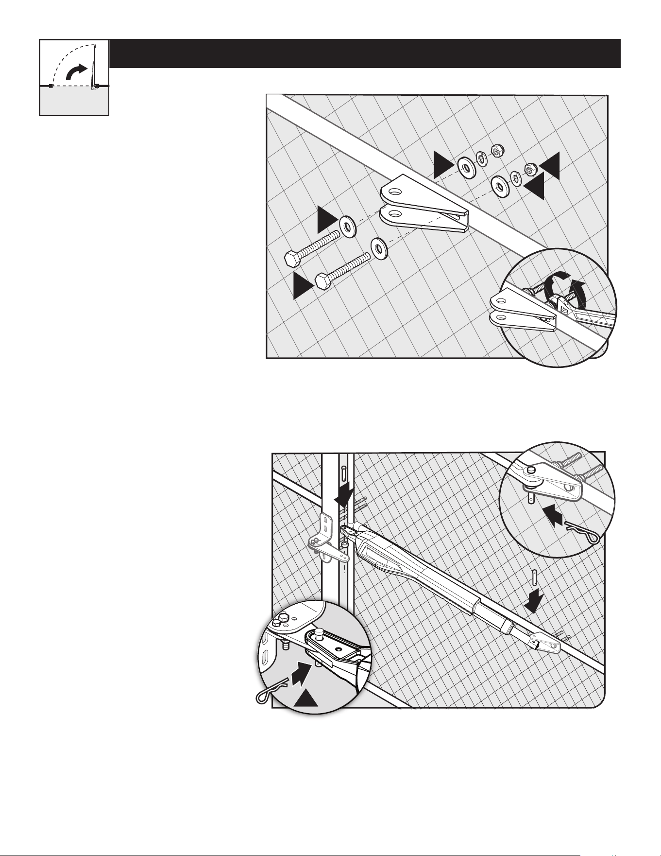
● Secure the gate post bracket subassembly
with the supplied hardware as shown.
● Using a drill and 7/16” drill bit, drill the
necessary holes to mount the gate post and
gate brackets.
Note: Some installations may require
additional reinforcement be installed on the
gate. See page 17.
M
L
T
Your Property
MM571W / MM572W Installation Instructions
28
T
V
L
L
P
N
N
S
S
● Secure the gate bracket with the
supplied hardware as shown.
● Once the gate post and gate
brackets are installed, reattach
the operator arm.
● Ensure the operator arm is level,
adjusting the post bracket location
if necessary.
● Once level, ensure all hardware is
tight.
● Remove excess bolt length with a
hacksaw.
PUSH-TO-OPEN OPERATOR MOUNTING
Step 10
Step 11
Your Property
MM571W / MM572W Installation Instructions
29
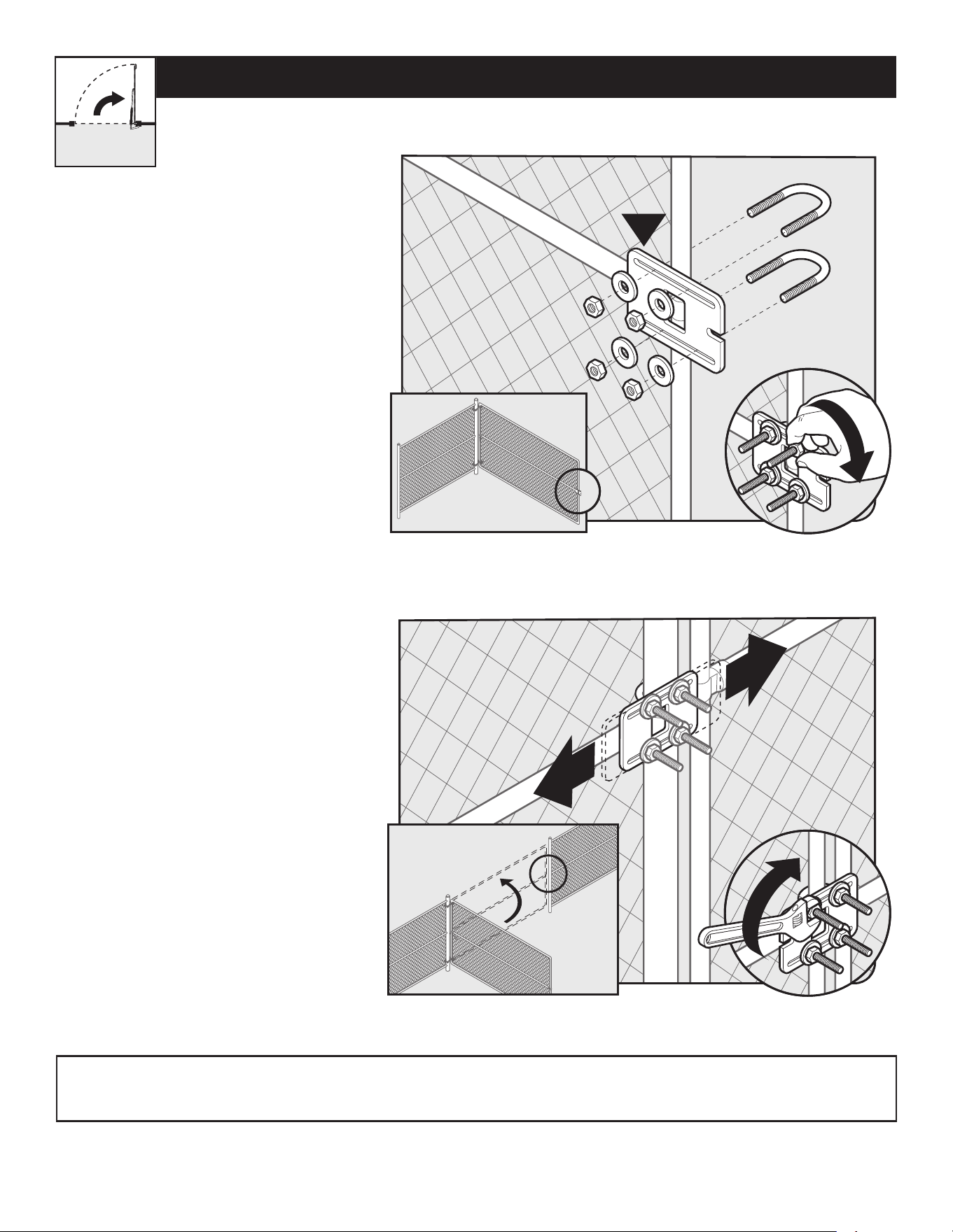
● Remove the operator from the gate post
and gate brackets.
● Swing the gate to the open position.
● With the gate fully open, install the closed
position stop plate on the gate opposite
the operator (hardware not included).
● Do not fully tighten hardware until after
the next step.
INSTALLING THE CLOSED POSITION STOP PLATE / PUSH-TO-OPEN
H
1
1
2
Step 1
Step 2
● Swing the gate to the closed position,
and adjust the closed position stop plate
against the fence post.
● Tighten the mounting hardware.
● With the gate in the closed position,
reinstall the operator arm.
Your Property
Note: For MM572W installations, the closed position stop plate should be installed on the leading edge of the PRIMARY gate leaf,
and adjusted to close against the leading edge of the SECONDARY gate leaf.
MM571W / MM572W Installation Instructions
30
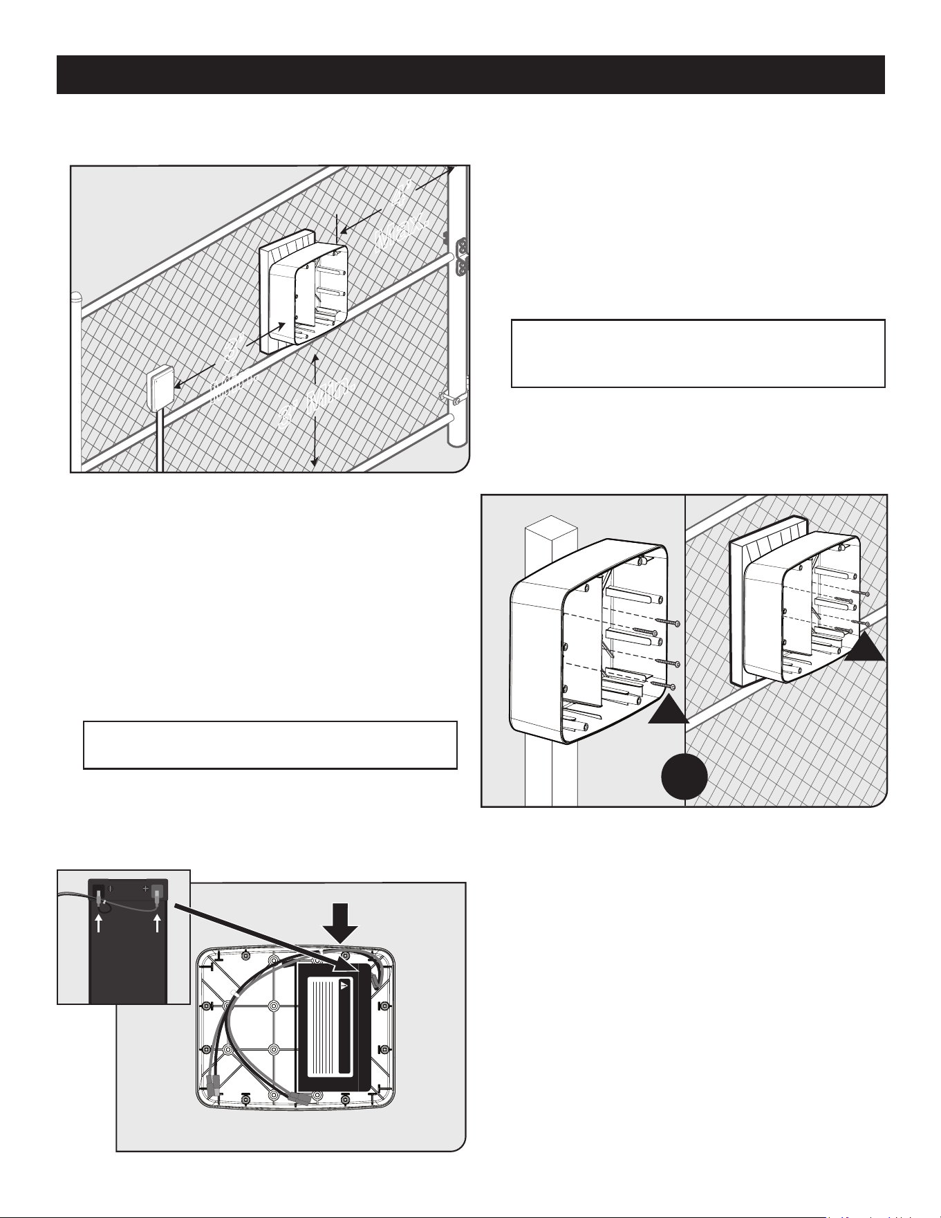
CONTROL BOX INSTALLATION
● Identify a suitable mounting location for your control box
at least 3 ft. from the ground and no more than 4 ft. from
the primary operator.
● Once you’ve identied a suitable mounting location, mount
the battery box using the supplied wood screws.
● If the mounting surface is not wood (such as a metal post),
you must use a wood panel between the box and the metal
post requiring additional hardware (not supplied).
● Connect the battery harness to the battery as shown - red
to positive, black to negative terminals.
● Place the battery into the right side of the battery box with
the terminals facing to the right and towards the top of the
battery box.
● Route the battery harness as shown.
DANGER/POISON
R
OR
R
3’ Min.
3’
Min.
4’
Max.
Step 1
Step 2
Step 3
Note: Always try to mount control box as high
as possible to improve radio performance. The
recommended location is at least 5 ft. from the ground.
Note: Orient the battery box with the arrow on the
inside of the box pointed up.
MM571W / MM572W Installation Instructions
31
CONTROL BOX INSTALLATION
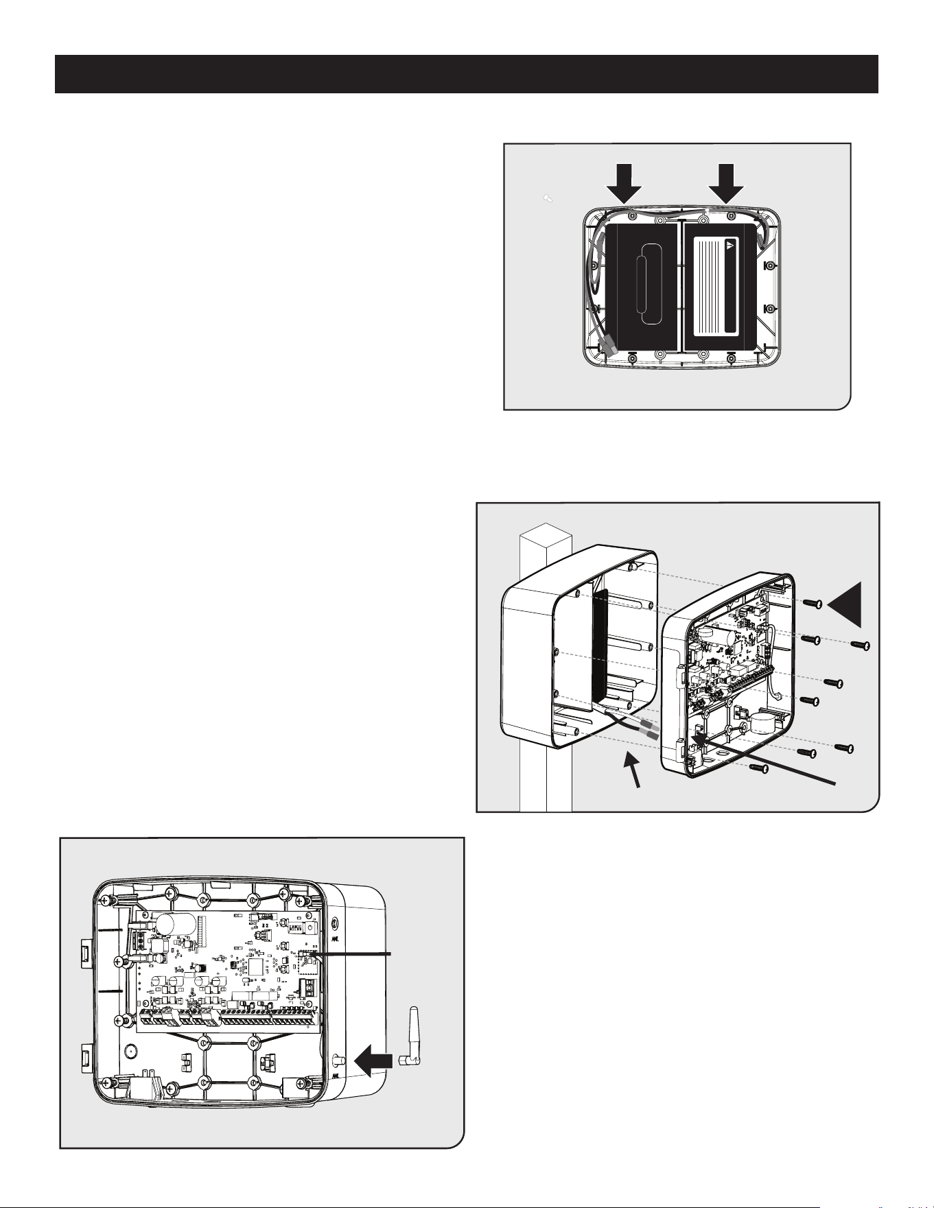
● If installing an optional second battery, connect the battery
harness as shown in Step 3.
● Place the second battery and route harness as shown.
● With the 7/32” drill bit, drill through the eight control
board panel access holes labeled “B”.
● Locate and knock out the battery cable access hole in
the panel.
● Feed the battery cables through the control board
casing access hole.
● Attach the control board casing using the eight screws
provided.
NOTE: Figure does not display the control box cover.
The cover will be attached on hinges.
● Install the Antenna by screwing it in place on the
SMA connector.
● Orient the antenna straight upward, and securely
tighten.
DANGER/POISON
CONSTANT VOLTAGE CHARGE
Feed battery cables through access hole
W
Antenna
Cable
Step 4
Step 5
Step 6
MM571W / MM572W Installation Instructions
32
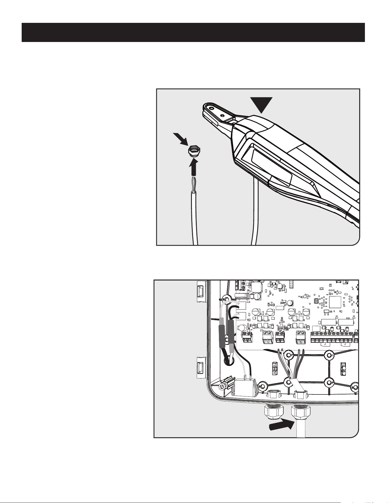
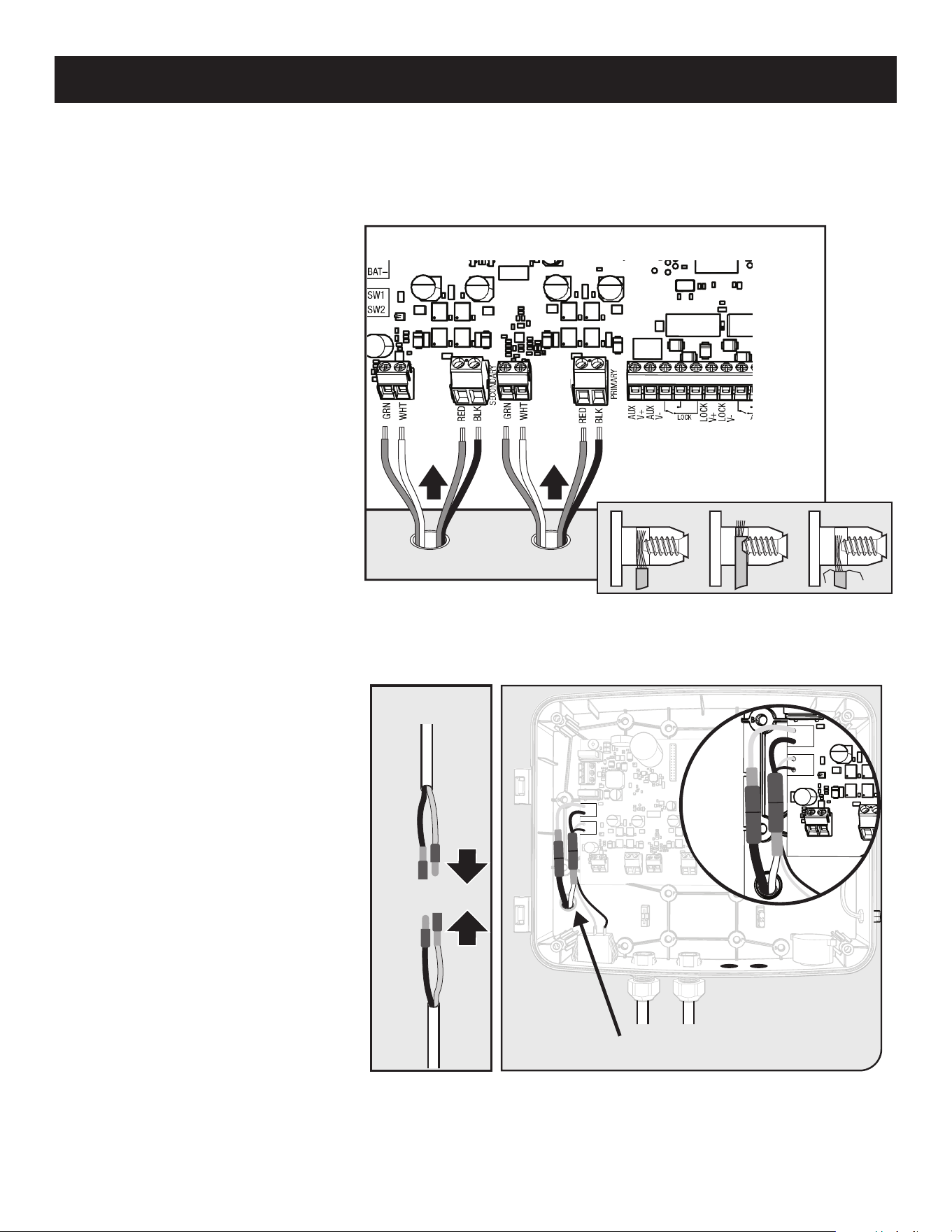
CONNECTING THE OPERATOR(S) AND BATTERY
GRN
WHT
BAT+
RESET
BAT–
GRN
WHT
RED
BLU
RED
BLU
COM
COM
AUX
V+
AUX
V-
LOCK
V+
LOCK
V-
PRIMARY
SECONDARY
LOCK AUX
SW1
SW2
SECURE SEALING NUT
B
SEALING NUT
● Remove the sealing nut from one of
the cable glands on the bottom of the
control box.
● Feed the operator wiring harness
through the sealing nut.
● For 572W, repeat for the SECONDARY
operator.
● Insert the wire harness through the
cable gland into the control box at
least 3” to allow connection to the
operator wiring terminals.
● Secure the cable in place by
tightening the sealing nut.
● For 572W, repeat for the SECONDARY
operator.
Step 1
Step 2
MM571W / MM572W Installation Instructions
33
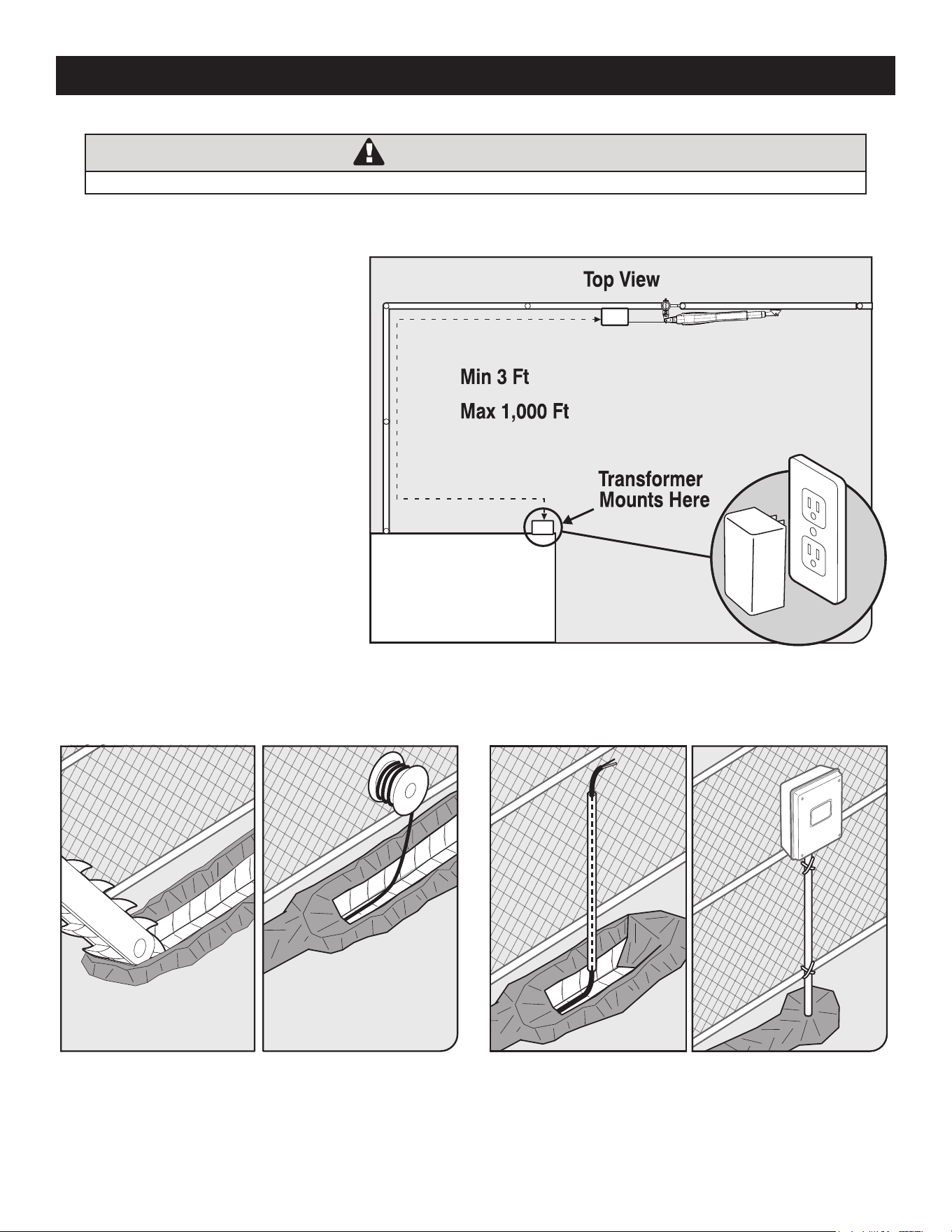
CONNECTING THE OPERATOR(S) AND BATTERY
Secondary Operator
Correct
Wrong Wrong
● Locate the PRIMARY operator wiring
terminals, and insert the wires into
the corresponding color terminals.
● For the 572W, locate the SECONDARY
operator wiring terminals, and insert
the wires from the SECONDARY
operator.
● Tighten the screw terminals ensuring
the wires are captured correctly as
shown
Step 3
Step 4
C
GRN
WHT
BAT+
AUTO
CLOSE
RESET
PULL
STAGGER
WARNING
BAT–
GRN
WHT
RED
BLK
RED
BLK
COM
COM
CYCL
SAFE
EXIT
SHDW
AUX
V+
AUX
V-
LOCK
V+
LOCK
V-
CLOSE
EDGE
OPEN
EDGE
PRIMARY
SECONDARY
LOCK AUX
SW1
SW2
PUSH
12345
+
TERM6
GRN
WHT
BAT+
BAT–
GRN
WHT
BRN
ORG
RED
BLK
RED
BLK
AUX
V+
AUX
V-
PRIMARY
SECONDARY
SW1
SW2
TERM6
Battery Power Access
BATT– BATT+
+
+
+
–
–
SW1–
SW1+
–
BATT– BATT+
● Connect the battery power wires:
Red to Red (BAT+) and Black to
Black (BAT–).
MM571W / MM572W Installation Instructions
34
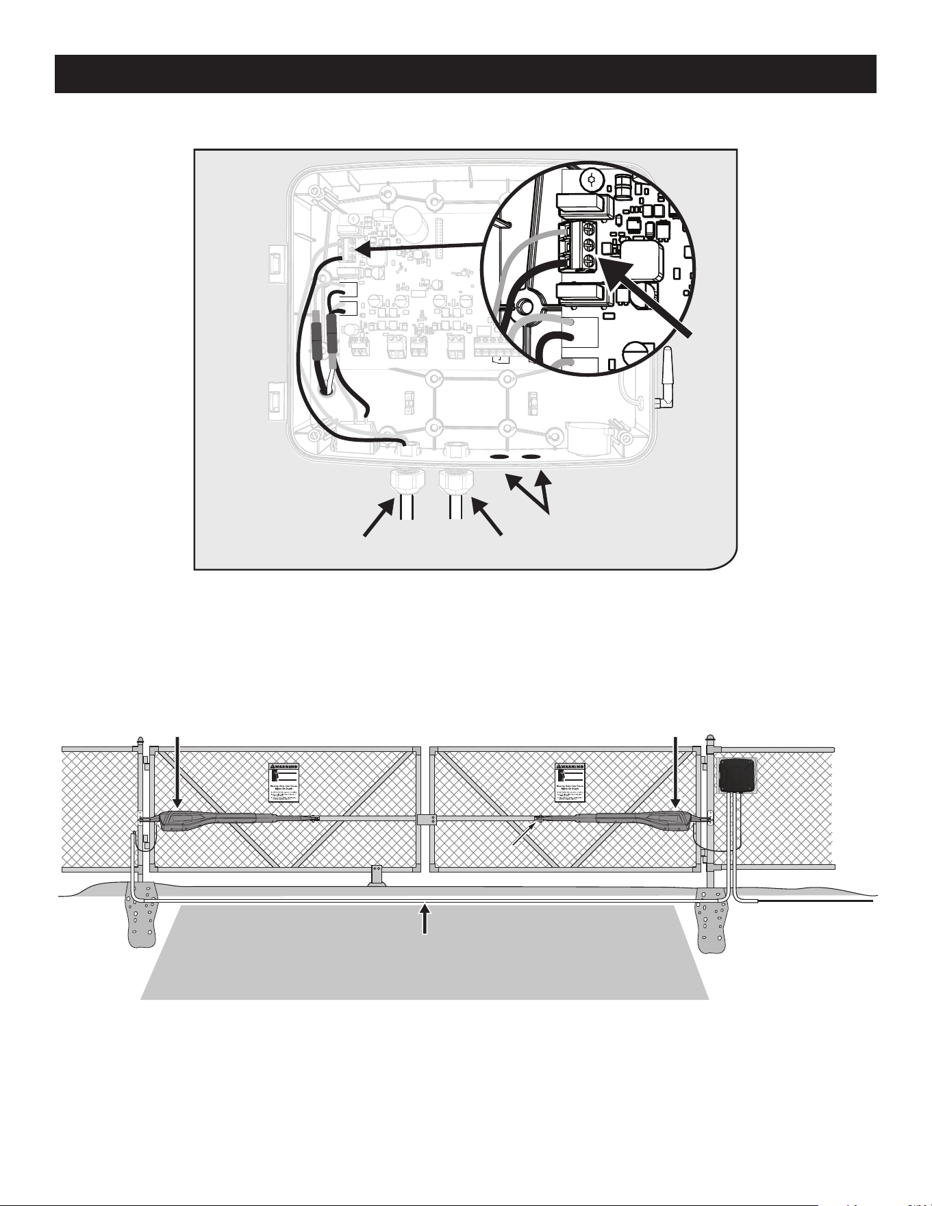
TRANSFORMER OR SOLAR PANEL WIRING INSTALLATION
WARNING
Before digging contact local authorities to locate underground utilities such as electric and gas service.
Step 1
Step 2
● Locate power outlet and identify wire
path to control box.
● If installing a solar panel (FM123 sold
separately), see solar panel instruction
manual and skip to Step 3.
● Note: If your outlet is outside, you must
use a weatherproof cover.
● Along the identied path between outlet and control box, dig a trench to lay the low voltage transformer wire (RB509 sold
separately).
● Use PVC conduit from the ground up to the control box.
● Conduit in trench is recommended.
CAUTION: Please
call your power company
before you dig. Failure to
do so could cause injury
or even death.
MM571W / MM572W Installation Instructions
35
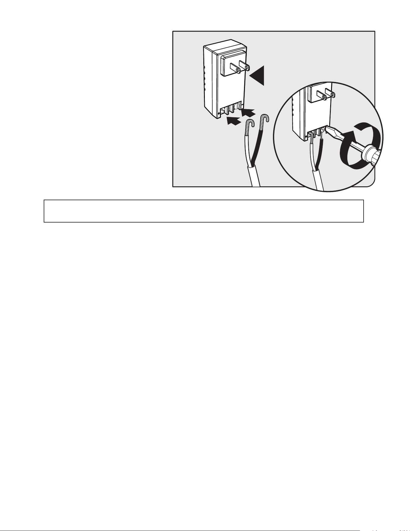
TRANSFORMER OR SOLAR PANEL WIRING INSTALLATION
GRN
WHT
BAT+
AUTO
CLOSE
RESET
PULL
STAGGER
WARNING
BAT–
GRN
WHT
RED
BLK
RED
BLK
COM
COM
CYCL
SAFE
EXIT
SHDW
AUX
V+
AUX
V-
LOCK
V+
LOCK
V-
CLOSE
EDGE
OPEN
EDGE
PRIMARY
SECONDARY
LOCK AUX
SW1
SW2
PUSH
12345
+
TERM6
AUTO
CLOSE
RESET
PULL
STAGGER
WARNING
COM
COM
CYCL
SAFE
EXIT
SHDW
CLOSE
EDGE
OPEN
EDGE
PUSH
12345
+
GRN
WHT
BAT+
BAT–
GRN
WHT
BRN
ORG
RED
BLK
SECONDARY
SW1
SW2
TERM6
Operator Arm Cable/Power Access
Alternate Access
+
–
● Feed the transformer or solar panel wires into the control box using one of the access locations on the bottom of the box.
● Connect the RED wire to PWR+ and the BLACK wire to PWR- on TERM 6 as shown.
Step 3
Step 3B (MM572 Only)
● Cut a 6" deep slot into the driveway to accommodate PVC conduit (not provided) for the power cable coming from the
Second opener to the control box. The buried conduit will protect the 44 foot power cable from automobile tires, lawn mower
blades, weed eaters, and grazing animals.
● Pull the secondary operator cable through the conduit.
● Repeat steps 1-3 (pages 16-17) for connecting the SECONDARY operator cable to the control board.
Second gate opener
Master gate opener
Run PVC conduit (not included) under driveway to protect
second opener power cable and low voltage wire.
MM571W / MM572W Installation Instructions
36
Step 4
MM572 Installation - For dual arm installation, drill through one of the Alternate Access slots to install the
Transformer or Solar power wires.
C
GRN
WHT
BAT+
AUTO
CLOSE
RESET
PULL
STAGGER
WARNING
BAT–
GRN
WHT
RED
BLK
RED
BLK
COM
COM
CYCL
SAFE
EXIT
SHDW
AUX
V+
AUX
V-
LOCK
V+
LOCK
V-
CLOSE
EDGE
OPEN
EDGE
PRIMARY
SECONDARY
LOCK AUX
SW1
SW2
PUSH
12345
+
TERM6
GRN
WHT
BAT+
BAT–
GRN
WHT
BRN
ORG
RED
BLK
RED
BLK
AUX
V+
AUX
V-
PRIMARY
SECONDARY
SW1
SW2
TERM6
Battery Power Access
BATT– BATT+
+
+
+
–
–
SW1–
SW1+
–
BATT– BATT+
● From the other end of the low voltage wire,
strip 1/2” from both the RED and BLACK
wire.
● On the transformer, connect RED wire to the
screw terminal marked + and BLACK wire
to the screw terminal marked -.
● Plug the transformer into the selected
electrical outlet.
Note: Use of a surge protector is strongly
recommended.
MM571W / MM572W Installation Instructions
37
DIP SWITCHES SETTINGS
Electrical Installation and Setup
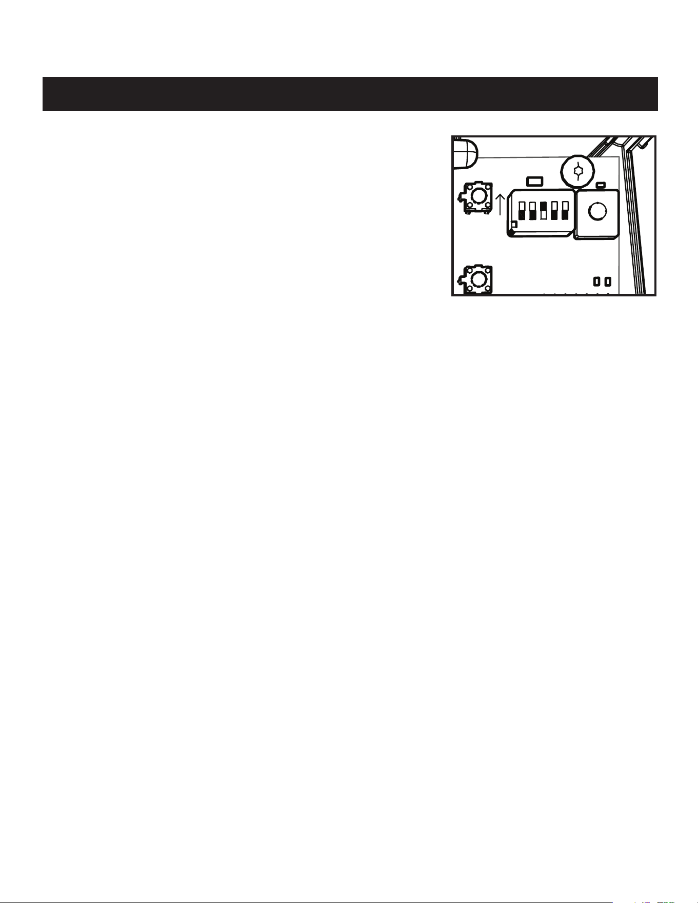
1. Push/Pull-to-Open
● On � = Push
● Off
❚
= Pull
For changes to this switch to take effect, the unit must be reset or power cycled.
2. Stagger
● For dual gate installations (MM572W),
● OFF - Gates will open simultaneous, but close staggered.
● ON - Gates will stagger while opening and closing for compatibility with gate
locks.
3. Warning
● The WARNING DIP switch toggles a movement alarm ON or OFF.
Powering the System
● Locate the ON/OFF switch on the bottom left of the control box.
● Toggle the switch to the ON position.
● The system will take approximately 20 seconds to power up indicated by an audible tone and LED D17 will ash.
10017426-CtrlBox_CoverOFF.ai
GRN
WHT
BAT+
AUTO
CLOSE
RESET
PULL
STAGGER
WARNING
SOFT S/S
BAT–
GRN
WHT
BRN
ORG
BRN
ORG
RED
BLU
RED
BLU
COM
COM
CYCL
SAFE
EXIT
SHDW
AUX
V+
AUX
V-
LOCK
V+
LOCK
V-
CLOSE
EDGE
OPEN
EDGE
PRIMARY
SECONDARY
LOCK AUX
SW1
SW2
PUSH
S2
S5
ON
12345
+
MM571W / MM572W Installation Instructions
38
S2
S4
S3
LED1
LED2
LED3
TRANSMITTER PROGRAMMING
WARNING:
Changes, modications or adjustments not expressly approved by Nortek Security & Control, LLC could void the user’s
authority to operate this equipment. There Are No User Serviceable Parts.
2
2
1
1
S2
S4
S3
LED1
LED2
LED3
S2
S4
S3
LED1
LED2
LED3
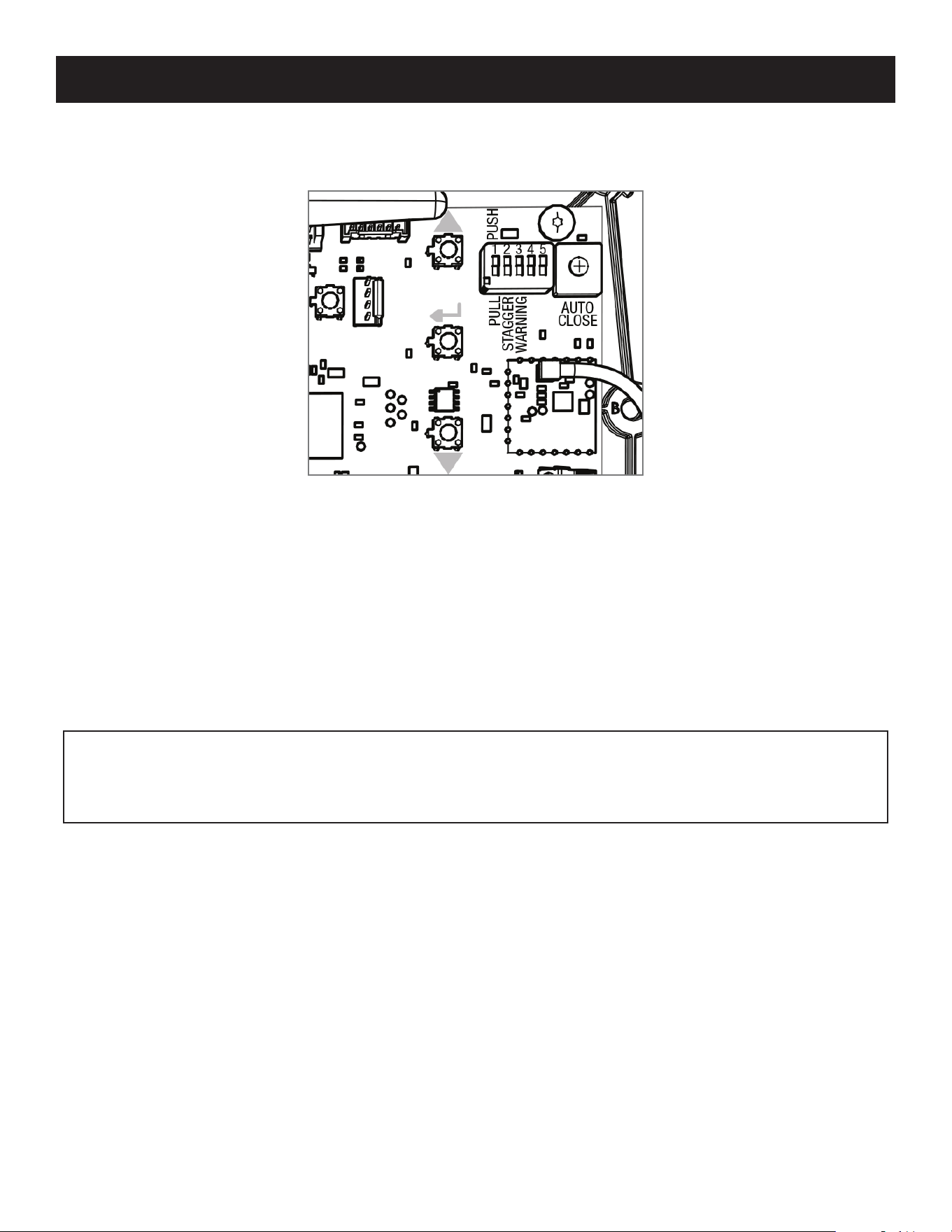
How to Erase a Transmitter or Keypad (MMK200) code:
Repeat steps 1-2 above to erase the learned transmitter or keypad code.
How to Erase ALL Learned Transmitters or Keypad codes:
1. Enter the 'Learn Transmitter' mode following step 1 above.
2. Press and hold the (down arrow) button until LED1, 2 & 3 ash and the buzzer sounds. (Approximately 10 seconds.)
Note: The control board can store a total of 50 transmitter and/or keypad codes. The system is compatible with Mighty Mule DIP
switch transmitters and keypads.
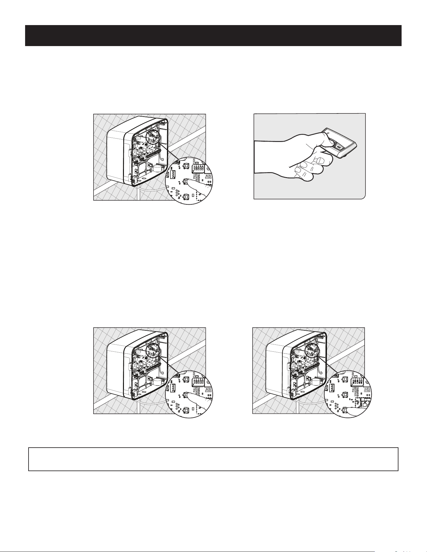
How to Learn a Transmitter:
1. On the control board, press and hold the (return/enter) button until LED2 beside the (return/enter) button turns on and the
buzzer sounds. Release the (return/enter) button.
2. Press and hold the desired transmitter button. Once learned, LED2 will ash and the buzzer will sound indicating that the
transmitter has been learned.
MM571W / MM572W Installation Instructions
39
CLOSED LIMIT PROGRAMMING - PULL TO OPEN
NOTE:
If you hear three short beeps in succession, that means that the programming mode has timed out and you will
need to enter the programming mode again. You do not have to start the positioning all over. If the closed position is already
correct but you have timed out, press and hold S2 and S3 until the buzzer sounds, then release. Then, immediately press
and hold S3 until the buzzer sounds and then release.
571 Closed Limit Programming
For Pull-to-Open Applications
Step 1: Enter the primary arm limit programming mode.
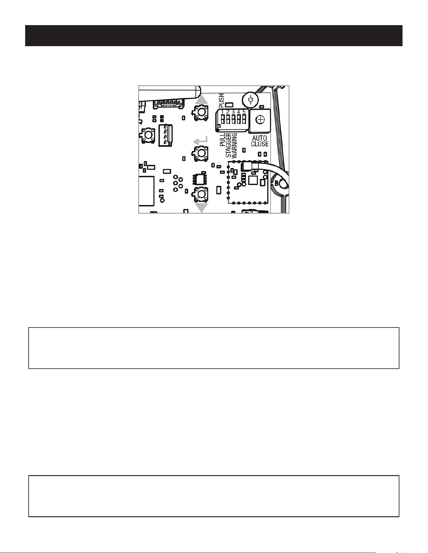
With the power on for your control box, press and hold both the S2 and the S3 buttons at the same time until LED 1 turns on and
the buzzer sounds, and then release them.
Step 2: Program the primary arm closed limit.
1. Next, press and hold S2 and you will hear a long beep and the arm will begin to extend, closing the gate. Continue holding the
button down until the gate reaches the desired closed position, and then release.
2. If you overshoot the desired closed position, you can use S4 to reverse the gate.
3. Adjust as needed until you are totally satised with the closed position. Then, press and hold S3 until the buzzer sounds, and
then release.
LED 1
S4
LED 2
LED 3
S3
S2
MM571W / MM572W Installation Instructions
40
572 Closed Limit Programming
For Pull-to-Open Applications
Step 1: Enter the secondary arm limit programming mode.
With the power on for your control box, press and hold both the S3 and the S4 buttons at the same time until LED 3 turns on and
the buzzer sounds, and then release them.
Step 2: Program the secondary arm closed limit.
1. Next, press and hold S2 and you will hear a long beep and the arm will begin to extend, closing the gate. Continue holding the
button down until the gate reaches the desired closed position, and then release.
2. If you overshoot the desired closed position, you can use S4 to reverse the gate.
3. Adjust as needed until you are totally satised with the closed position. Then, press and hold S3 until the buzzer sounds, and
then release.
Step 3: Enter the primary arm limit programming mode.
With the power on for your control box, press and hold both the S2 and the S3 buttons at the same time until LED 1 turns on and
the buzzer sounds, and then release them.
Step 4: Program the primary arm closed limit.
4. Next, press and hold S2 and you will hear a long beep and the arm will begin to extend, closing the gate. Continue holding the
button down until the gate reaches the desired closed position, and then release.
5. If you overshoot the desired closed position, you can use S4 to reverse the gate.
6. Adjust as needed until you are totally satised with the closed position. Then, press and hold S3 until the buzzer sounds, and
then release.
CLOSED LIMIT PROGRAMMING - PULL TO OPEN
NOTE:
If you hear three short beeps in succession, that means that the programming mode has timed out and you will
need to enter the programming mode again. You do not have to start the positioning all over. If the closed position is
already correct but you have timed out, press and hold S3 and S4 until the buzzer sounds, then release. Then, immediately
press and hold S3 until the buzzer sounds and then release.
NOTE: If you hear three short beeps in succession, that means that the programming mode has timed out and you will
need to enter the programming mode again. You do not have to start the positioning all over. If the closed position is
already correct but you have timed out, press and hold S2 and S3 until the buzzer sounds, then release. Then, immediately
press and hold S3 until the buzzer sounds and then release.
LED 1
S4
LED 2
LED 3
S3
S2
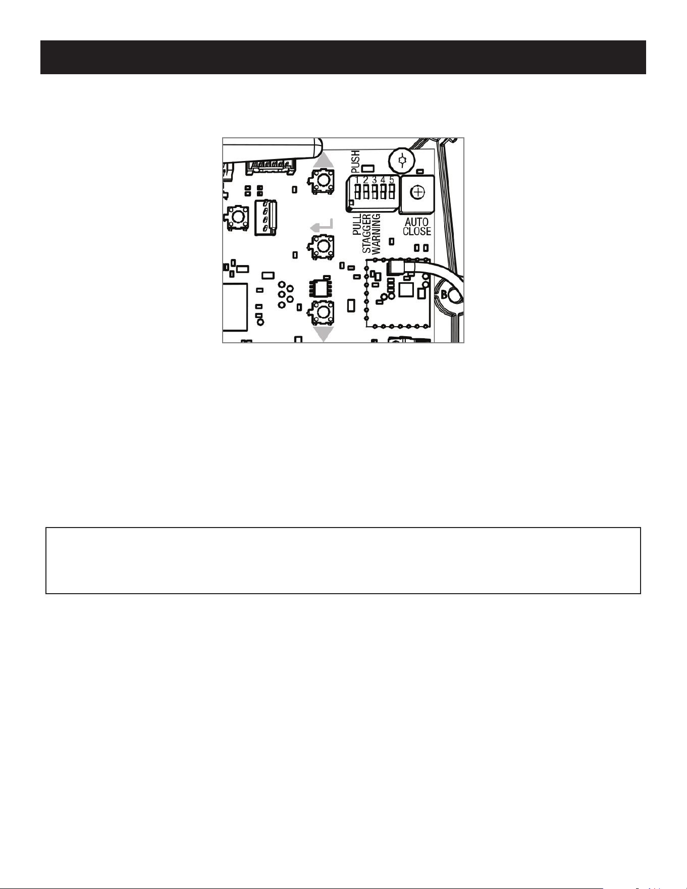
MM571W / MM572W Installation Instructions
41
CLOSED LIMIT PROGRAMMING - PUSH TO OPEN
NOTE:
If you hear three short beeps in succession, that means that the programming mode has timed out and you will
need to enter the programming mode again. You do not have to start the positioning all over. If the open position is already
correct but you have timed out, press and hold S2 and S3 until the buzzer sounds, then release. Then, immediately press
and hold S3 until the buzzer sounds and then release.
571 Open Limit Programming
For Push-to-Open Applications
Step 1: Enter the primary arm limit programming mode.
With the power on for your control box, press and hold both the S2 and the S3 buttons at the same time until LED 1 turns on and
the buzzer sounds, and then release them.
Step 2: Program the primary arm closed limit.
1. Next, press and hold S2 and you will hear a long beep and the arm will begin to extend, opening the gate. Continue holding
the button down until the gate reaches the desired open position, and then release.
2. If you overshoot the desired open position, you can use S4 to reverse the gate.
3. Adjust as needed until you are totally satised with the open position. Then, press and hold S3 until the buzzer sounds, and
then release.
LED 1
S4
LED 2
LED 3
S3
S2
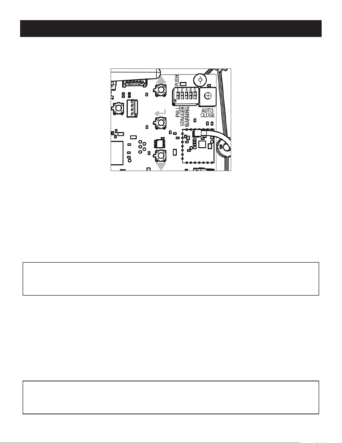
MM571W / MM572W Installation Instructions
42
572 Open Limit Programming
For Push-to-Open Applications
Step 1: Enter the primary arm limit programming mode.
With the power on for your control box, press and hold both the S2 and the S3 buttons at the same time until LED 1 turns on and
the buzzer sounds, and then release them.
Step 2: Program the primary arm closed limit.
1. Next, press and hold S2 and you will hear a long beep and the arm will begin to extend, opening the gate. Continue holding
the button down until the gate reaches the desired open position, and then release.
2. If you overshoot the desired open position, you can use S4 to reverse the gate.
3. Adjust as needed until you are totally satised with the open position. Then, press and hold S3 until the buzzer sounds, and
then release.
Step 3: Enter the secondary arm limit programming mode.
With the power on for your control box, press and hold both the S3 and the S4 push buttons at the same time until LED 3 turns
on and the buzzer sounds, and then release them.
Step 4: Program the secondary arm open limit.
4. Next, press and hold S2 and you should hear a long beep and the arm will begin to extend, opening the gate. Keep holding the
button down until the gate reaches the desired open position, and then release.
5. If you overshoot the desired open position, you can use S4 to retract the arm in.
6. Adjust as needed until you are totally satised with the open position. Then, press and hold S3 until you the buzzer sounds,
and then release.
CLOSED LIMIT PROGRAMMING - PUSH TO OPEN
NOTE:
If you hear three short beeps in succession, that means that the programming mode has timed out and you will
need to enter the programming mode again. You do not have to start the positioning all over. If the open position is already
correct but you have timed out, press and hold S2 and S3 until the buzzer sounds, then release. Then, immediately press
and hold S3 until the buzzer sounds and then release.
NOTE: If you hear three short beeps in succession, that means that the programming mode has timed out and you will
need to enter the programming mode again. You do not have to start the positioning all over. If the open position is already
correct but you have timed out, press and hold S3 and S4 until the buzzer sounds, then release. Then, immediately press
and hold S3 until the buzzer sounds and then release.
LED 1
S4
LED 2
LED 3
S3
S2

MM571W / MM572W Installation Instructions
43
DUAL SENSE STALL FORCE SETTING
Do not use the Dual Sense Stall Force adjustment to compensate for a gate that is sticking or binding. Excessive Stall force may
cause damage to the gate operator or gate system.
The Stall Force adjustment controls the amount of force the opener will apply against an obstruction before it stops and reverses
direction. The controller includes three Stall Force settings, and is preset from the factory to Low. If your operator stops and
reverses during a normal cycle, follow the instructions below to change the Stall Force setting.
Adjusting the Stall Force:
1. Press and hold the and buttons until the buzzer sounds (approximately 2 seconds). Release.
2. Use the and to adjust the Stall Force setting. LED1, 2, & 3 are used to indicate the setting. LED3 ON indicates LOW,
LED3 & 2 ON indicates MEDIUM, and LED1, 2 & 3 ON indicates HIGH.
3. Press the
button until the buzzer sounds, then release to set the Stall Force setting.
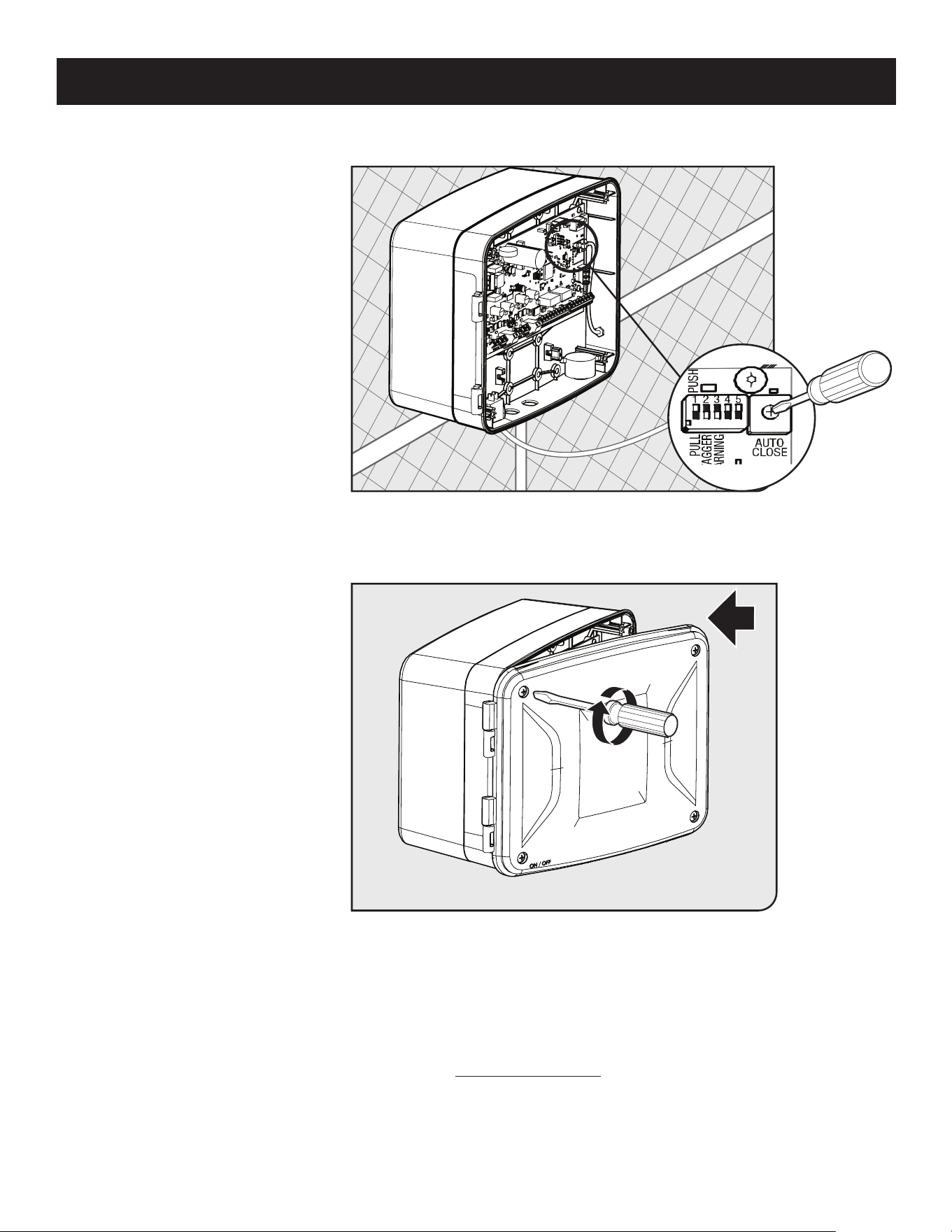
MM571W / MM572W Installation Instructions
44
This product has the ability of being control via a smart device (i.e. smartphone) with the addition of the MMS100 smart kit.
Refer to the instructions contained in the MMS100 kit or visit www.mightymule.com for more information
AUTO CLOSE SETTING
Optional Smart Control Setup
● The auto close timer is set to OFF
from the factory.
● To set an auto close timer, use a
small at head screw driver to
turn the auto close potentiometer
clockwise.
● The timer can be set from
approximately 3 seconds to a
maximum of 120 seconds.
• • • • • •• • • • • • • • •
● If you have additional accessories
or external devices to install, see
the following page.
● Unless you have additional external
accessories to install, your gate
operator installation is now
complete.
● Please review the installation
checklist at the end of this manual.
● Use a phillips head screwdriver to
close the control box.
Step 1
Step 2
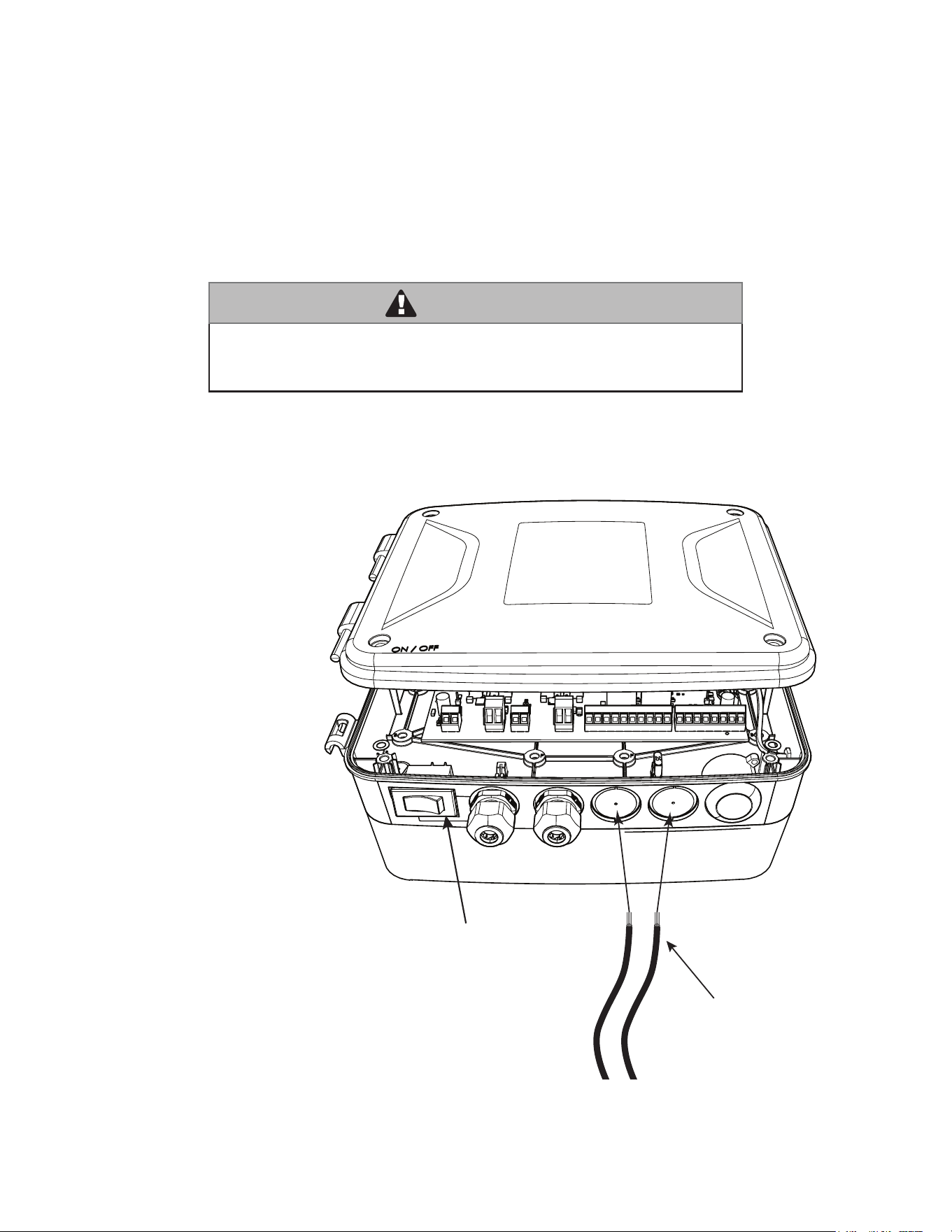
MM571W / MM572W Installation Instructions
45
Wiring Accessories through Control Board Wiring Knockout
Carefully remove wiring
knockout plugs to insert
accessory wires.
Open the control box cover.
Close the control box cover.
Insert accessory wires
through the knockout and
route to the accessory input
terminals on the control
board.
(See pg. 12)
ON/OFF Switch
Accessory Wires
(Photo beams, Exit/Vehicle Sensor etc.)
Mighty Mule strongly recommends the use of additional obstruction detection devices however we do not endorse any specic
brand names. Only use products that are listed to be in compliance with any applicable UL safety standards and national and
regional codes.
PLEASE NOTE: Contact sensors, non-contact sensors, shadow loops, etc. are not included with this product. Refer to the
sensor manufacturer’s instructions for information about installing accessory devices.
The Mighty Mule ONLY accepts accessory devices with normally open dry contact outputs.
Connecting Additional Devices
WARNING
Make sure the operator power switch is turned OFF before connecting
ANY device wiring to the terminals of the controller. Unplugging the
transformer does not turn power to the operator off.
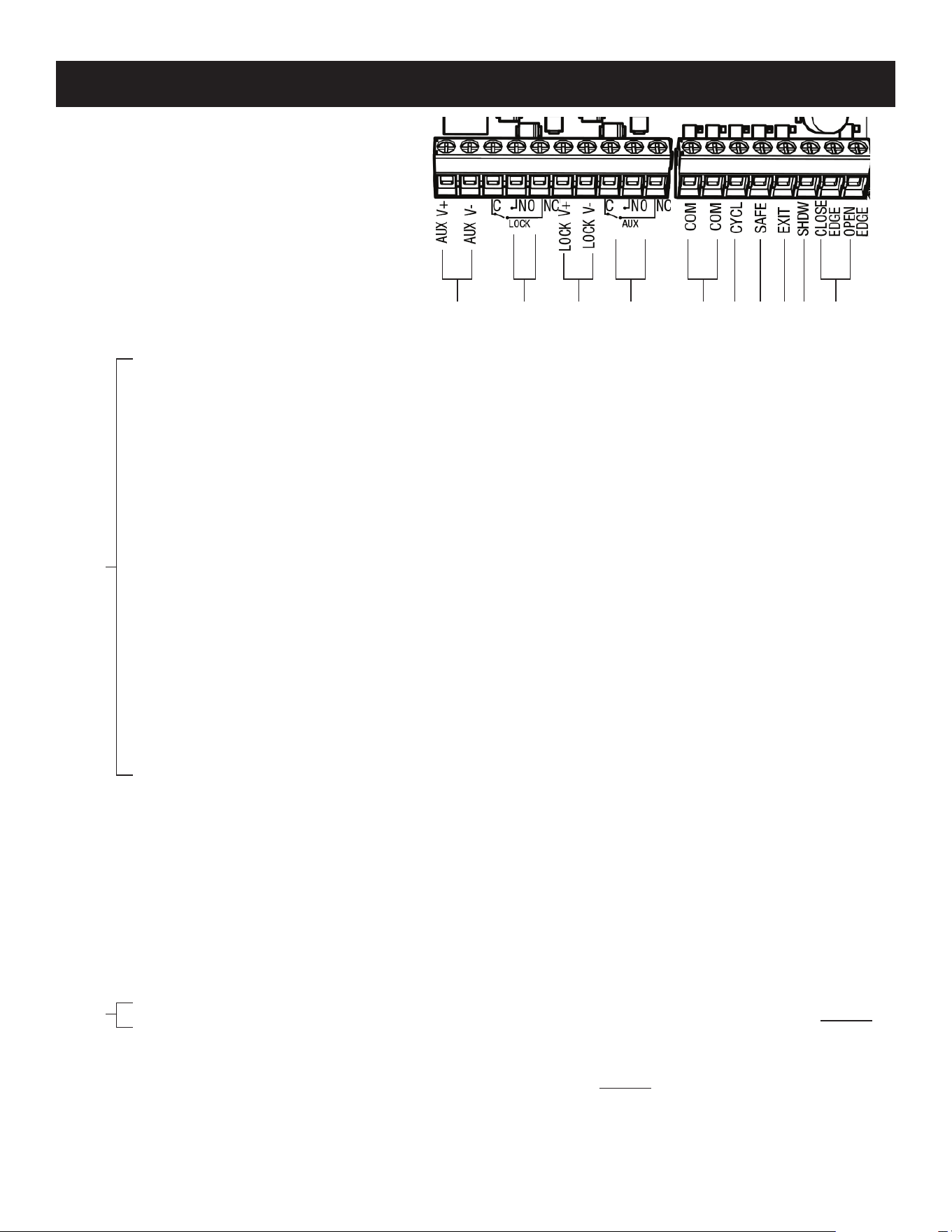
MM571W / MM572W Installation Instructions
46
1 COM: Common/Negative terminal for accessory devices and negative wire from solar panel(s).
2 CYCL: (Typically for use with doorbell button or hard wired keypad)
• Each activation at this input will cycle the operation as follows:
….→ OPEN → STOP → CLOSE → STOP → OPEN → …
3 SAFE: (Typically for use with photo beam device,loop detector or other non-contact sensors)
• Activation of this input while the gate is closing, or at a position other than fully open or fully closed
will cause the gate to stop and return to the opened position.
• Activation of this input while the gate is opening has no effect. (gate will continue to open)
• Activation of this input while the gate is open will prevent gate from closing.
• Activation of this input while at open limit will restart the auto close time (if enabled).
4 EXIT: (Typically for use with exit loop or wand)
• Activation of this input will open the gate if it’s not already at the open position.
• Activation of this input while at open limit will restart the auto close time (if enabled).
5 SHDW: (Typically for use with loop detector device)
• This input is only monitored when the gate is at the fully open position.
At any other position, activation of this input has no effect on gate operation.
• Activation of this input while gate at the fully open position will prevent gate from closing.
6 EDGE: (Typically for use with contact edge sensor)
• Activation of this input while gate is moving will cause it to reverse direction for 2 seconds.
• Activation of this input while idle will prevent gate from running.
NOTES:
● All ACCESSORY INPUTS (ITEMS 2-6) are dry
contact,normally open inputs. DO NOT apply
external voltage inputs to these terminals.
● All ACCESSORY INPUTS (ITEMS 2-6) are
connected with respect to the COMMON
terminals (ITEM 1).
LOCK
OUTPUTS
ACCESSORY INPUTS
CONTROL BOARD CONNECTIONS
7 AUX V+ & AUX V-: These terminals provide constant auxiliary accessory power from the operator's battery, rated
for 2 amps MAX. The output is designed to be used in conjunction with the AUX relay, ITEM 8.
NOTE: Using this power output will drain your operator battery. Continuous use greater than 20mA is NOT recommended for
solar applications.
8 AUX C NO NC: The AUX Relay is triggered during gate operation and remains activated for the duration of the gate
operation. The AUX Relay should only be used for switching AUX V-.
9 LOCK V+ & LOCK V-: These terminals are designed for use with the Automatic Gate Lock (FM143). See page 47 of
this manual for connection diagrams.
10 LOCK C NO NC: The LOCK Relay is designed for use with the Automatic Gate Lock (FM143). This relay is
momentarily triggered at the beginning of each gate operation. See page 47 of this manual for connection
diagrams. The LOCK Relay should only be used for switching LOCK V-.
NOTE: DO NOT connect positive voltage to the AUX or LOCK Relays.
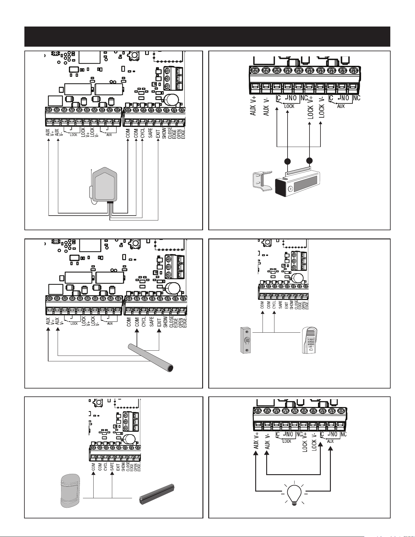
MM571W / MM572W Installation Instructions
47
CONNECTING ACCESSORIES
Yellow & Shield
Black Blue
Red
Mighty Mule Vehicle Sensor
Refer to the Vehicle Sensor Manual for additional information if needed.
Automatic Gate Lock (FM143)
+
-
NOTE: A wire jumper is required between
'LOCK V-' and 'LOCK Relay Common'.
Mighty Mule
Push Button Control
NOTE: Connections are for typical applications.
For additional connection options not illustrated
here refer to the accessory manual for details.
Mighty Mule Keypad
For FM130/FM130-SW and FM136,
see Appendix A in this manual.
Black
Green
Brown
Blue
Yellow
Red
Garage Door Receiver
Photo Beams Edge Sensor
Additional
Jumper Wire
Light Bulb (active while cycling)

MM571W / MM572W Installation Instructions
48
● Monthly, test the obstruction and entrapment protection systems.
● Monthly, service the gate operator (make sure the power switch is OFF). Clean extended operator arm with a
soft, dry clean cloth.
● On all gates weighing 250 lb. or more, routinely grease the ball bearing hinges at least 4 times a year; more
frequently if the gates are near a coastal area.
● Monthly, turn off the power switch and disconnect the Mighty Mule and move the gate to make sure the
gate is moving freely without sticking or binding. Lubricate the hinges or repair the gate as required before
reattaching the Mighty Mule.
● Monthly, check the gate system for potential entrapments from new landscaping or construction. Eliminate
or guard as required.
● Monthly, check that the warning signs are mounted on each side of the gate and clearly visible. Replace the
signs if they are missing or damaged.
● Replace batteries every 2-3 years and properly recycle old batteries.
Maintenance
MM571W / MM572W Installation Instructions
49
Audible Feedback Possible Diagnosis Check/Solution
Continuous Alarm
Control Board senses an obstruction
or lack of arm movement
h Path of gate
h Gate for adequate maintenance, free swinging, level and plumb
h Adjust Stall Force level
h Disconnect obstruction detection devices
h 2” clearance not met (see page 17)
h Arm power cable connections
1 beep every 10 seconds Low battery
h Check fuses
h Battery harness connections
h Battery under load or inadequate charge
h AC output at 120 Vac, transformer output at 19 Vdc
h Solar panel(s) output based on weather conditions
h Wiring from charge source to control board, verify correct polarity
2 beeps every 10 seconds Motor fault
h Operator arm(s) connections
h Internal motor short
h Check fuses
h Battery harness connections
h Battery under load or inadequate charge
1 beep, pause, 1 beep,…… Open circuit Primary arm
h Primary arm connections (white and green)
h Arm power cable
2 beeps, pause, 2 beeps,…… Open circuit Secondary arm
h Secondary arm connections (white and green)
h Arm power cable
3 beeps, pause, 3 beeps,…… Short circuit Primary arm
h Primary arm connections (white and green)
h Arm power cable
4 beeps, pause, 4 beeps,…… Short circuit Secondary arm
h Secondary arm connections (white and green)
h Arm power cable
5 beeps, pause, 5 beeps,……
Stuck limit switch Primary Arm or
reading open motor circuit
h Arm power cable wires shorted, crossed or cut/disconnected
6 beeps, pause, 6 beeps,……
Stuck limit switch Secondary arm or
reading open motor circuit
h Arm power cable wires shorted, crossed or cut/disconnected
If your gate operator does not function properly after it is installed, use this guide before calling the Nortek Security & Control
Service Department.
Troubleshooting Guide - Audible Feedback

MM571W / MM572W Installation Instructions
50
Audible Feedback Possible Diagnosis Check/Solution
1 beep, pause, 2 beeps, pause, 1
beep, pause, 2 beeps, pause,......
Reading primary motor short
condition
h Turn the system off and back on.
h Motor leads shorted
h Internal arm problem, or control board problem
1 beep, pause, 3 beeps, pause, 1
beep, pause, 3 beeps, pause,......
Reading secondary motor short
condition
h Turn the system off and back on.
h Motor leads shorted
h Internal arm problem, or control board problem
The unit clicks with no arm
movement
Internal motor problem or low
battery
h Internal arm problem
h Check fuses
h Battery harness connections
h Battery under load
h Inadequate charge
Additional information can be found by contacting Nortek Security & Control.

MM571W / MM572W Installation Instructions
51
If your gate operator does not function properly after it is installed, use this guide before calling the Nortek Security & Control
Service Department.
Troubleshooting Guide - Visual Feedback
Visual
Feedback
Possible Diagnosis Check/Solution
The unit does not seem to
turn on
Blown fuse(s)
Lack of power
Power switch
h Ensure the unit is switched on
h Check fuses
h Battery harness connections
h Battery under load or inadequate charge
Unit requires powercycle in order to reset
the error
LED 2 (red) 1 blink, pause, 1
blink,......
Cycle (CYCL) terminal shorted
Detach all wires connected to the affected terminal. Turn the
system power off and back on. After the start up beep, ensure
the system functions as expected. Troubleshoot each accessory
that was removed and associated wiring individually.
LED 2 (red) 2 blinks, pause,
2 blinks,......
Safety (SAFE) terminal shorted
LED 2 (red) 3 blinks, pause,
3 blinks,......
Exit (EXIT) terminal shorted
LED 2 (red) 4 blinks, pause,
4 blinks,......
Shadow (SHDW) terminal shorted
LED 2 (red) 5 blinks, pause,
5 blinks,......
Close Edge (CLOSE EDGE) terminal
shorted
LED 2 (red) 6 blinks, pause,
6 blinks,......
Open Edge (OPEN EDGE) terminal
shorted
Charge LED rapidly ashing
Unit does not detect the presence of
a battery
h Check fuses
h Battery harness connections
h Battery under load or inadequate charge
Charge LED off Unit not charging
h Check fuses
h Battery harness connections
h Battery under load or inadequate charge
h AC output at 120 Vac, transformer output at 19 Vdc
h Solar panel(s) output based on weather conditions
h Wiring from charge source to control board, verify correct
polarity
Charge LED Flashing Battery or Batteries disconnected
Connect battery/batteries

MM571W / MM572W Installation Instructions
52
Visual Feedback
Possible
Diagnosis
Check/Solution
The unit will not run 1) Closed / open limit(s) not
programmed
2) Transmitter not
programmed
3) Battery issues
4) Arm problem
h Program closed / open limit(s), see pages 39-42
h Program transmitter
h Check fuses
h Battery harness connections
h Battery under load or inadequate charge
h Check arm connections to control board, and then turn the system off
and back on. If there is a click and no movement, there is an issue
with the arm or power cable
The unit stops before reaching
the proper open or close
position.
Limit position not adjusted/set
correctly.
The unit is receiving a stop
command
Hardware not positioned
correctly
h Reset the extended limit position. Note: if this problem has occurred,
make sure the resetting of limit(s) begins with the operator arm fully
retracted. Do not spin the tube out by hand in order to attach it to the
gate bracket.
h Adjust the arm’s retracted position by moving or repositioning the
hardware.
h Adjust the arm hardware (this would correct the retracted position of
the arm)
h Check for a triggered (stuck) transmitter or accessory by removing
batteries from all other wireless accessories.
The unit reverses before
completing an open or close.
Gate/unit has sensed an
obstruction
h Path of gate
h Gate for adequate maintenance, free swinging, level and plumb
h Adjust Stall Force level
h Disconnect obstruction detection devices
h 2” clearance not met (see page 17)
h Arm power cable connections
The auto close seems to be
working in reverse and/or
accessories not operating
properly
Dip switch 1 in the wrong
position, or was not updated by
the system
h Turn unit off then back on
h Move dip 1 to the correct position, and then turn unit off then back on
h Check accessories and connections
F1 fuse (top left) blown Transformer or solar wired to
board incorrectly
h Correct wiring
h Replace fuse
F2 fuse (bottom left fuse)
blown
Battery or Batteries connected
incorrectly
h Check battery connections and harness, ensure the battery is
connected red to red (+) and black to black (-)
h Replace F2 fuse and harness fuse if blown
Harness fuse blown Battery or Batteries connected
incorrectly
h Check battery connections and harness, ensure the battery is
connected red to red (+) and black to black (-)
h Replace harness fuse and F2 fuse if blown
Additional information can be found by contacting Nortek Security & Control.
MM571W / MM572W Installation Instructions
53
1. First use the procedures found in the Maintenance &
Troubleshooting Guide (see page 48).
2. For 24 hour 7 days a week trouble shooting and
support online go to our TECH WIZARD site at
www.mightymule.com
3. If you are unable to solve the problem, call the
Tech Service Department at 800-543-1236.
4. If repair or replacement of your gate operator is necessary,
the Service Department will assign a Return Authorization
(RA) number.
5. Include a copy of your receipt and securely pack the
component(s) authorized for return to the factory. Write the
RA number issued to you on the outside of the package in
LARGE BOLD PRINT. Ship the package(s) freight prepaid to
the address provided during the RA process.
If your Mighty Mule Gate Opener is not operating properly, please follow the steps below:
NOTE: Products returned to Nortek Security & Control without a Return Authorization (RA) number in
LARGE BOLD PRINT on the outside of the package WILL NOT be accepted. Items returned to Nortek
Security & Control freight collect WILL NOT be accepted. Items returned without proof of purchase
will not be repaired under warranty.
The Mighty Mule Technical Service Department is open
Monday – Friday 8:00 A.M. – 7:00 P.M. (Eastern Time)
Web site: www.mightymule.com
Telephone 800-543-1236
For 24 hour 7 days a week trouble shooting and support
online go to our TECH WIZARD site at...
www.mightymule.com
Repair Service
MM571W / MM572W Installation Instructions
54
Accessories are Available From Your Retail Store
Accessories
Solar Panel (FM123)
The Solar Panel is a 10 watt solar powered battery charger for use with the Mighty Mule 571W/572W gate operator
systems. Particularly suited for remote installations, each Solar Panel comes with tubular steel support, mounting clips,
wire connectors, and 10 ft. of low voltage wire [see Low Voltage Wire for additional wire (250’ maximum]. The Mighty
Mule control board has clearly labeled terminal connections for easy installation of the Solar Panel. Installation in some
regions of the world will require multiple solar panels for adequate charging power (30 watt max).
Wireless Transmitter (MMT103)
The MMT103 Code Safe digital transmitter is a wireless radio control designed for use with Mighty Mule garage door
openers and can also be programmed to your Mighty Mule gate openers. One remote for two or three devices.
®
Pin Lock (FM133)
The Pin Lock substitutes for the clevis pin at the front end of the Mighty Mule gate operators. Helps prevent theft of the
operator from the gate, while allowing quick release of the operator.
Wireless Driveway Vehicle Sensor (FM130)
Automatically activates gate operator “Hands-Free” when a vehicle exits the property. 100 ft. range between transmitter
and receiver. Easy installation.
Wireless Connectivity System (MMS100)
Adds smart functionality to your gate operator utilizing the Mighty Mule App.
PAIR
RESET
Wireless Keypad (MMK200)
The Mighty Mule Wireless Keypad is designed to control access to all Mighty Mule Garage Door Openers. This keypad
features a LED back light that allows you to see numeric keys throughout dark or unfavorable weather conditions.
®
Mounting Post (FM100) - In Ground
This black powder coated pedestal is designed to provide convenient access to your keypad, wireless intercom, or other
access control device from your vehicle. With its break down design it is easy to install and works well in most standard
applications. Surface Mount Flanges (F102) and Extensions (F103) for added height are available.
Mighty Mule Vehicle Sensor (FM138)
The Gate Opening Sensor is designed for residential and agricultural applications and is compatible with most Mighty
Mule automatic gate operator models. The Sensor is an electromagnetic sensor, which offers ‘hands free’ operation of the
Mighty Mule Gate Operator with a 12 ft. radius of detection of vehicles in motion.
Automatic Gate Lock Pull-to-Open (FM143)
A MUST for added security. Solenoid driven, with a steel housing. Used with Mighty Mule DC swing gate operating
systems for maximum stability and security. Comes with a keyed manual release.
AUTOMATIC
GATE LOCK
®
ELECTRONIC SECURITY LOCK
MM571W / MM572W Installation Instructions
55
If you have a question about any special order item, call Customer Service: 1-800-543-4283
The contents of all material available on this installation manual are copyrighted by Nortek Security & Control, LLC (“Nortek Security & Control”), unless otherwise indicated. All rights
are reserved by Nortek Security & Control, and content may not be reproduced, downloaded, disseminated, published, or transferred in any form or by any means, except with the
prior, written permission of Nortek Security & Control. Any reprinting of Nortek Security & Control publications is by permission only. Copyright infringement is a violation of federal law.
Mighty Mule¨, E-Z Gate¨, Nortek Security & Control¨, “Dual Sense Technology” are registered trademarks of Nortek Security & Control, LLC, America’s DIY Automatic Gate Openers is a
trademark of Nortek Security & Control, LLC and are the exclusive property of Nortek Security & Control, LLC (“Nortek Security & Control”).
All rights are reserved by Nortek Security & Control, and these marks may not be used, in any for without the prior, written permission of Nortek Security & Control.
Replacement Transformer (RP1010)
19V, 2A, DC transformer for maintaining the battery with the Mighty Mule gate operator.
Push Button Control (FM132)
Unlit doorbell button for remote entry or exit control. Wires directly to the control board and uses 16-22 gauge stranded,
dual conductor low voltage wire (sold separately).
Low Voltage Wire (RB509-50 = 50’ / RB509-100 = 100’ / RB509-250 = 250’ / RB509-500 = 500’)
The 16 gauge, stranded, dual conductor Low Voltage Wire is for connecting the AC powered transformer, or the Solar
Panel to the control board. Also used for the connection of accessories, such as locks, keypads, push buttons and other
wired control devices. This specially designed wire is UV treated, PVC coated and ready for direct burial. Available in
1000’ rolls or special lengths.
Wireless Entry Intercom / Keypad (MM136)
Allows owner to screen guest at the gate before allowing access to the property. Keypad also allows owner to give up to
25 programmable entry codes to family, friends or approved delivery personnel. Codes can be permanent or temporary.
Up to 500 feet reception.
Additional base stations available, up to four total. (MM136B)
Garage Door Receiver (RB709U-NB)
The Garage Door Receiver allows you to use the same Mighty Mule entry transmitter to operate your gate operator and
your garage door operator. Compatible with most garage door operators (not compatible with the MMK200).
Driveway Alarm (FM231)
This device alerts you of vehicles entering your driveway (with or without an automated gate). The indoor base station
signals you with a door chime when a vehicle passes the driveway sensor.
Key Chain Two Button Transmitter (FM134)
The Key Chain Transmitter is a dual button version of the Mighty Mule single button entry transmitter and has the same
adjustable code settings. Used for 2 gates or 1 gate and garage door (when used with in conjunction with a garage door
receiver – RB709U-NB). (Battery is included).
Single Button Transmitter (FM135)
The Mighty Mule entry transmitter, with adjustable code settings, is standard equipment with all Mighty Mule systems.
(Battery is included.)
MM571W / MM572W Installation Instructions
56
Appendix A
FM130 Installation
For the FM130 to function, the “Transmitter Module” must be programmed to your gate
operator’s control board.
Before you begin:
● Ensure the gate operator is in the OPEN position.
● Check to ensure the PUSH-PULL DIP setting is correct (see page 14 and pages 39-42).
If you have to change this DIP setting, turn the unit OFF then ON to save setting.
● Ensure the AUTOCLOSE is set to OFF.
Step 1: Choose a random dip switch setting on the Transmitter Module.
Step 2: On the gate operator control board, press and hold the (
, S3) button until LED2
illuminates and the buzzer sounds. Release the button.
Step 3: Insert both batteries into the transmitter module. The transmitter module will begin transmitting.
Step 4: Once Learned, LED2 will ash and the buzzer will sound indicating that the Transmitter Module has been learned.
Remove the AA batteries from the Transmitter Module, and proceed with the rest of the installation following the
accessory instructions.
Notes:
1. If you need to erase this device, repeat steps 2-4 above.
2. Erasing all transmitters on the gate operator control board will erase this device.
3. AUTOCLOSE may be turned back on after setup is complete.
FM136 Installation
As an alternative to the instructions provided with the FM136, the keypad can be learned to your gate
operator as an additional transmitter by following these instructions:
Step 1: Choose a random DIP setting on the keypad unit. Refer to the FM136 manual for the location of the
DIP switches.
Step 2: On the gate operator control board, press and hold the (
, S3) button until LED2 illuminates and
the buzzer sounds. Release the button.
Step 3: Enter your MASTER CODE on the FM136 keypad (1-2-3-4 is the default unless changed). Once
learned, LED2 will ash and the buzzer will sound on the gate operator control board. Proceed with
installation of the FM136 per the accessory instructions.
Notes:
1. If you need to erase this device, repeat steps 2-3 above.
2. Erasing all transmitters on the gate operator control board will erase this device.
FM130
ACCESSORY INSTALLATION INSTRUCTIONS

MM571W / MM572W Installation Instructions
57
Gate Operator Installation Checklist
❑
1. The gate has been checked to make sure it is level and moves freely in both directions.
❑
2. Potential pinch areas have been guarded so as to be inaccessible OR have sensing edges and/or photo
beam obstruction detection devices installed.
❑
3. The installer has installed one or more contact or non-contact obstruction sensing devices, if required for
this installation.
❑
4. If pedestrian trafc is expected, a separate pedestrian gate has been installed, a minimum of seven feet
from the gate system. All pedestrian trafc must use the pedestrian gate.
❑
5. Warning signs have been installed on each side of the gate in highly visible locations. These signs must
remain at all times.
❑
6. There are no controls installed on the gate operator, or within 10 feet of the gate.
❑
7. The Dual Sense Technology™ feature has been properly adjusted to the minimum operational setting for
your application.
❑
8. Reviewed and understand all of the operational functions, obstruction sensing devices, warning beeper
and reset, etc.
❑
9. Review and understand the proper use of the operator’s manual disconnect feature. The manual
disconnect must never be used while the gate is in motion. The power switch must be turned off before
using the manual disconnect and disengaging the operator.
❑
10. Reviewed all safety instructions, and keep the safety instructions and owner’s information sheets for
reference.
❑
11. Review and understand the maintenance schedule for both the gate and the gate operator.
Telephone Mighty Mule Sales: (800) 543-4283
or Mighty Mule Technical Service: (800) 543-1236
www.mightymule.com
The contents of all material available on this installation manual are copyrighted by Nortek Security & Control, LLC (“Nortek Security & Control”), unless otherwise indicated. All rights are reserved by Nortek Security & Control, and content
may not be reproduced, downloaded, disseminated, published, or transferred in any form or by any means, except with the prior, written permission of Nortek Security & Control. Any reprinting of Nortek Security & Control publications is by
permission only. Copyright infringement is a violation of federal law.
Mighty Mule¨, E-Z Gate¨, NSC¨, “Dual Sense Technology” are registered trademarks of Nortek Security & Control, LLC, America’s DIY Automatic Gate Openers is a trademark of Nortek Security & Control, LLC and are the exclusive property of
Nortek Security & Control, LLC (“Nortek Security & Control”).
Copyright© 2021 Nortek Security & Control, LLC. All rights are reserved by Nortek Security & Control, and these marks may not be used, in any for without the prior, written permission of Nortek Security & Control.