Instructions for Gate Opener
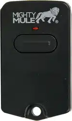
Single Button Entry Transmitter
FCC Regulation: This device complies with Part 15 of the FCC Rules. Operation is subject to the following two conditions: (1) This device may not cause harmful
interference, and (2) This device must accept any interference received, including interference that may cause undesired operation.
Warning: Changes or modifications to this unit not expressly approved by the party responsible for compliance could void the user’s authority to operate the equipment.
NOTE: This equipment has been tested and found to comply with the limits for a Class B digital device, pursuant to Part 15 of the FCC Rules. These limits are designed to
provide reasonable protection against harmful interference in a residential installation. This equipment generates, uses and can radiate radio frequency energy and, if not
installed and used in accordance with the instructions, may cause harmful interference to radio communications.
However, there is no guarantee that interference will not occur in a particular installation. If this equipment does cause harmful interference to radio or television reception,
which can be determined by turning the equipment off and on, the user is encouraged to try to correct the interference by one or more of the following measures:
• Reorient or relocate the receiving antenna.
• Increase the separation between the equipment and receiver.
• Connect the equipment into an outlet on a circuit different from that to which the receiver is connected.
• Consult the dealer or an experienced radio/TV technician for help.
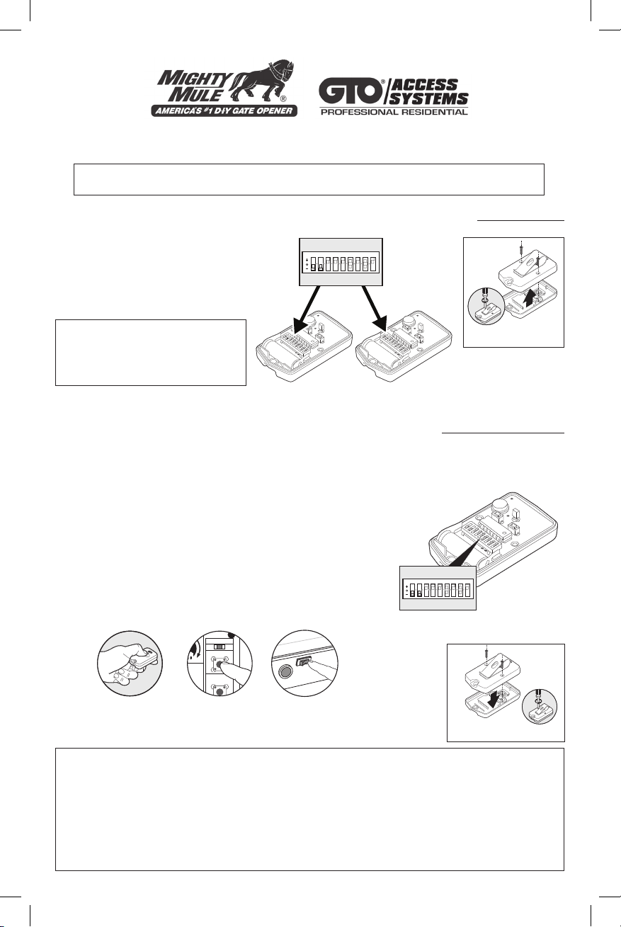
If you already have a transmitter that operates
your gate and are simply adding an additional
transmitter, set the DIP switches in the new
transmitter to match the DIP switches in
your original transmitter, reassemble the
transmitters and you are done.
If you are replacing a lost transmitter and you know or have your original transmitter’s DIP switch
setting written down, set the new transmitter DIP switches to that setting and it is ready to activate
your gate opener.
If you don’t know the DIP switch setting from your original transmitter,
you will need to select a new setting.
Personalize your Transmitter Setting
There are nine (9) DIP switches, each of which can be placed in
three different positions (+,0,-). DO NOT set all switches in the same
position, such as all +, all -, or all zeros.
Program New Transmitter Setting to Gate Opener’s Memory
Some gate openers are programmed with a LEARN REMOTE or
LEARN TRANSMITTER button and some with the ON/OFF switch.
Refer to your Gate Opener’s Installation Manual for instructions on
how to program the transmitter to your gate opener.
NOTE: If the red light on the transmitter is dim or flickers when the
transmitter button is pushed, the transmitter battery may be weak.
Replace when necessary with a A23S 12 Volt battery.
ORIGINAL
TRANSMITTER
NEW
TRANSMITTER
1 2 3 4 5 6 7 8 9
Instructions for adding additional entry transmitter(s)
Instructions for replacing a lost entry transmitter
You can have as many transmitters as you want for family and guests to open your gate.
The DIP switches in all the transmitters for a particular gate opener must be set the same.
1 2 3 4 5 6 7 8 9
1 2 3 4
ON
STATUS
LEARN RMT
LEARN
MAST LIMIT
S3
S2
OFF
SOFT START OFF
WARNING OFF
OPEN PULL
SLV OPEN DLY.
MODE1 OFF
MODE2 OFF
ON
ON
PUSH
SIMULT.
ON
ON
120 MIN MAX
AUTO CLOSE TIME STALL FORCE
ON/OFF
+
or
IMPORTANT:
If you change the DIP switches in the
original transmitter refer to Program
New Transmitter Setting to Gate
Opener’s Memory section below.
Open transmitter to
access DIP switches
Reassemble the
transmitter when finished

Your GTO
®
Accessory is warranted by the manufacturer against defects in materials and manufacturer workmanship for a period of one (1) year from date of purchase, provided the recommended installation procedures have been followed.
GTO
®
sells its products through authorized retail and on-line channels to ensure that consumers obtain quality pre-sale and after sale support and service. The warranty on GTO
®
products is NOT VALID if the products have been purchased
from an unauthorized, on-line E-tailer (e.g., E-bay® sellers who are not authorized GTO
®
resellers), or if a product’s serial number has been altered, removed, or replaced in any way. To verify that you are buying from an authorized, on-line
GTO
®
e-tailer, visit www.gtoinc.com, or call 1-800-543-GATE.
In the case of product failure due to defective material or manufacturer workmanship within the one (1) year warranty period, the opener will be repaired or replaced (at the manufacturer’s option) at no charge to the customer, if returned freight
prepaid to Gates That Open, LLC, 3121 Hartseld Road, Tallahassee, Florida, USA 32303. IMPORTANT: Call (850) 575-4144 or Fax (850) 575-8950 for a Return Goods Authorization (RGA) number before returning item(s) to the factory.
Products shipped to the factory without an RGA number will not be accepted. Replacement or repaired parts are covered by this warranty for the remainder of the one (1) year warranty period or six (6) months, whichever is greater. GTO
®
will
pay shipping costs (equal to United Parcel Service ground rate) for return to owner of item(s) repaired under warranty.
The manufacturer will not be responsible for any charges or damages incurred in the removal of the defective parts for repair, or the reinstallation of these parts after repair. Use of any components that are not GTO
®
specified (e.g. battery or
transformer) will void the warranty. This warranty shall be considered void if damage to the product(s) was due to improper installation or use, use of non-GTO
®
specified or approved components or replacement parts, connection to an improper
power source, or if damage was caused by lightning, electrical power surge, wind, fire, flood, insects, or other natural agents.
This warranty gives you specific legal rights, and you may also have other rights which may vary from state to state. This warranty is in lieu of all other warranties, either expressed or implied.
After the one (1) year warranty period expires, GTO
®
(or one of its authorized service centers) will perform necessary repairs for a nominal fee. Call GTO
®
at (800) 543-1236 or (850) 575-4144 for more information.
ONE YEAR LIMITED WARRANTY
If you have any questions or concerns, please contact our Technical Service Department • M-F 8:00 am to 5:00 pm (ET) at 1-800-543-1236 or 850-575-4144.
Gates That Open, LLC • 3121 Hartseld Road • Tallahassee, Florida 32303 • Telephone (850) 575-0176 • Fax (850) 575-8912 • website www.gtoinc.com
1. Match the eight DIP switches found in
the dual button transmitter to the first
eight DIP switches in the single button
transmitter.
2. The ninth DIP switch on the single
button transmitter cannot be in the
lowest position (-); it must be changed
to the upper (+) or middle (0) position
at this time.
3. If the ninth DIP switch is set to the
upper position (+) the left hand button
will be used to send the same code
when using the dual button remote.
4. If the ninth DIP switch is set to the
middle position (0) the right hand button will be used to send the
same code when using the dual button remote.
5.
If you change the ninth DIP switch in the original transmitter refer
to Program New Transmitter Setting to Gate Opener’s Memory
section below.
The two button transmitter is used for the remote control of two gate openers
or a gate opener and a garage door opener. A GTO Universal Receiver
(RB709U-NB) is required for use with garage door openers.
Instructions for Gate Opener
Two Button Entry Transmitter
If you already have a Two Button transmitter that operates your gates and are simply adding an
additional Two Button transmitter, set the DIP switches in the new transmitter to match the DIP switches
in your original transmitter, reassemble the transmitters and you are done.
If you are replacing a lost transmitter and you know or have your original transmitter’s DIP switch
setting written down, set the new transmitter DIP switches to that setting and it is ready to activate
your gate opener.
If you don’t know the DIP switch setting from your original transmitter, you
will need to select a new setting.
Personalize your Transmitter Setting
There are eight (8) DIP switches, each of which can be placed in three
different positions (+,0,-). DO NOT set all switches in the same position,
such as all +, all -, or all zeros.
Program New Transmitter Setting to Gate Opener’s Memory
Some gate openers are programmed with a LEARN REMOTE or LEARN
TRANSMITTER button and some with the ON/OFF switch. Refer to your
Gate Opener’s or Universal Receiver’s Installation Manual for instructions
on how to program the transmitter to that device.
NOTE: If the red light on the transmitter is dim or flickers when the transmitter
button is pushed, the transmitter battery may be weak. Replace when
necessary with a A23S 12 Volt battery.
Instructions for adding additional entry transmitter(s)
Instructions for replacing a lost entry transmitter
1 2 3 4 5 6 7 8
1 2 3 4
ON
STATUS
LEARN RMT
LEARN
MAST LIMIT
S3
S2
OFF
SOFT START OFF
WARNING OFF
OPEN PULL
SLV OPEN DLY.
MODE1 OFF
MODE2 OFF
ON
ON
PUSH
SIMULT.
ON
ON
120 MIN MAX
AUTO CLOSE TIME STALL FORCE
ON/OFF
+
or
Open transmitter to
access DIP switches
Reassemble the
transmitter when finished
If you are matching your two button transmitter to a single button
transmitter follow these steps:
ORIGINAL SINGLE
BUTTON TRANSMITTER
NEW TWO BUTTON
TRANSMITTER
1 2 3 4 5 6 7 8 9 1 2 3 4 5 6 7 8
Left button activates the same device
as a single button transmitter with 9th
DIP switch in the upper (+) position.
Right button activates the same device
as a single button transmitter with 9th
DIP switch in the middle (0) position.