C-Lift Guard
EN
2026-03
V01R02
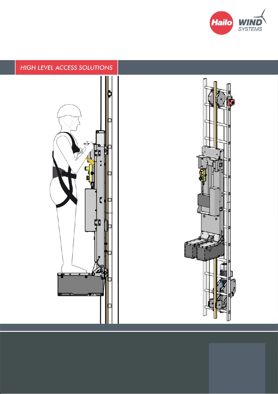
Access platform
Operating instructions - Original document

Contents
Legal notice
Contact:
Hailo Wind Systems USA Inc.
1395 Mineral Springs Road
Elberton, GA 30635
USA
Phone:
+1 (0) 706 283 4500
Fax:
+1 (0) 706 283 4600
E-Mail:
info@hailo-windsystems.us
Internet:
www.hailo-windsystems.com/en
© Hailo Wind Systems – Without the prior written consent of Hailo Wind Systems, no part of this publication may
be reproduced in any way, transmitted, transcribed, stored in a storage medium or translated into any language
or computer language. Copyright infringement may also affect the product support by Hailo Wind Systems for
this equipment. Hailo Wind Systems reserves the right to make changes to this manual and the product it describes
without prior notice. The content of this manual does not include any contractual or other obligations by Hailo
Wind Systems and is not legally binding. This publication was prepared with great care. However, should you find
any errors or wish to make suggestions for improvement, please write to Hailo Wind Systems. The original
language of this document is German. If required, you can request a copy in writing.

Contents
Operating instructions · C-Lift Guard
V01R02 · · 2026-03
3
Contents
1 About This Document ........................................................................................................................................... 5
1.1 Classification of the warnings ............................................................................................................................. 5
2 General instructions ............................................................................................................................................... 6
2.1 Warranty and limitations of liability ................................................................................................................. 6
2.2 Obligations of the operatoring company and user ..................................................................................... 6
3 Safety .......................................................................................................................................................................... 7
3.1 Residual risks ............................................................................................................................................................ 8
3.2 FCC Compliance ...................................................................................................................................................... 9
3.3 ISED Canada Compliance ..................................................................................................................................... 9
3.4 Safety instructions ................................................................................................................................................ 10
3.5 Markings on the access platform .................................................................................................................... 13
3.6 Type plates .............................................................................................................................................................. 14
4 Technical Data ....................................................................................................................................................... 15
5 Design and function............................................................................................................................................. 16
5.1 Main components of the access platform .................................................................................................... 16
5.2 Function of the access platform....................................................................................................................... 18
5.3 Travel limiters ......................................................................................................................................................... 18
5.4 Safety switch-offs ................................................................................................................................................. 19
5.5 Other safety devices ............................................................................................................................................ 20
6 Operation ................................................................................................................................................................ 21
6.1 Workday preparation – Daily Check ............................................................................................................... 21
6.2 Control panel on the access platform ............................................................................................................ 23
6.3 Control cabinet ...................................................................................................................................................... 23
6.4 LED display on the transmitter ......................................................................................................................... 24
6.5 Passenger operation with the access platform ........................................................................................... 25
6.6 Automatic travel and material transport ....................................................................................................... 27
6.7 Remote operation with the operating panel ............................................................................................... 29
6.8 Exiting the access platform ................................................................................................................................ 30
7 Evacuation from the access platform ............................................................................................................. 31
8 Troubleshooting .................................................................................................................................................... 32
8.1 Operational readiness ......................................................................................................................................... 32
8.2 Error indications .................................................................................................................................................... 32
8.3 Schedules and maintenance intervals ............................................................................................................ 34
9 Daily Check – Logbook ....................................................................................................................................... 35
10 Inspection plans .................................................................................................................................................... 43
10.1 Annual inspection plan ............................................................................................................................... 43

Operating instructions · C-Lift Guard
V01R02 · · 2026-03
4
10.2 Inspection plan after 5 years ..................................................................................................................... 44
11 Inspection reports................................................................................................................................................. 46
About This Document
Operating instructions · C-Lift Guard
V01R02 · · 2026-03
5
1 About This Document
These operating instructions describe the use, maintenance and testing
of the access platform C-Lift Guard and are only valid for this product.
Please read this information brochure completely and observe all
safety instructions before using the access platform.
1.1 Classification of the warnings
Classification of the
warnings
Warnings are introduced by signal words that express the extent of
the hazard. A distinction is made between four types of warnings:
DANGER
DANGER indicates an imminently threatening dangerous situation
which could lead to serious injuries or death if not avoided.
WARNING
WARNING indicates a potentially dangerous situation which could
lead to serious injuries or death if not avoided.
CAUTION
CAUTION indicates a potentially dangerous situation which could
lead to minor injuries if not avoided.
ATTENTION
ATTENTION indicates a potentially dangerous situation which could
lead to machine damage if not avoided.
Presentation of important
information:
NOTICE
This symbol is used to draw your attention to important or helpful
information.
General instructions
Operating instructions · C-Lift Guard
V01R02 · · 2026-03
6
2 General instructions
2.1 Warranty and limitations of liability
Warranty
The manufacturer’s warranty for the C-Lift Guard totals 2 years.
The warranty of the manufacturer or the commissioned assembly
company for the assembly work is 2 years.
Limitation of liability
Hailo Wind Systems is not liable for damage resulting from violations
of the specifications presented here.
Prohibition of unauthorized
modifications to the
machine
The machine may not be modified or expanded without the prior
written consent of the manufacturer. There is a danger to life if the
safety devices are changed!
Hailo Wind Systems is not liable for damage caused by unauthorized
modifications.
2.2 Obligations of the operatoring company and user
NOTICE
The term operatoring company is used in this manual for the party
that holds the authority and responsibility for this access platform –
usually a company or corporation.
The person who uses the access platform is referred to as the user.
Responsibilities of the user
and the operatoring
company
It is the operating company’s responsibility to ensure that the access
platform is correctly installed, configured and commissioned, operated,
maintained and serviced, and that this work is only carried out by
persons who have been appropriately trained for these tasks.
It is likewise the responsibility of the operating company to ensure that
the access platform is fully compliant with laws and regulations
applicable to the location where the machine is installed and operated.
It is the operating company’s responsibility to operate the access
platform in accordance with all safety instructions and procedures
described in these operating instructions, as well as in accordance with
all other safety precautions applicable at your workplace.
Availability of the operating
instructions
The operating instructions are part of the documentation for the access
platform. They must be available in full on the access platform and be
accessible to all persons who operate the access platform.
Rescue plan
The operating company is obliged to prepare a corresponding rescue
plan for the event of an emergency. This specifies what to do in the
event of danger and accidents.

Safety
Operating instructions · C-Lift Guard
V01R02 · · 2026-03
7
Authorized users
Persons who have been trained by the manufacturer in handling the
access platform, have read and understood the operating instructions
and are able to operate the access platform safely.
Service personnel for
assembly and maintenance,
especially for the electrical
system
Persons who have been trained by the manufacturer in the use of the
access platform and who, due to their professional training, are able to
carry out the work assigned to them and to independently identify and
avoid possible hazards.
Country-specific regulations must be observed!
Training by the Safety
Rescue Academy (S.A.R.A.)
More information on service training from Hailo Wind Systems can be
found at www.hailo-windsystems.com/sara.
3 Safety
Intended use
The climbing platform is used exclusively for transporting persons or
work material (carried on the person or optionally in a material box if it
does not obstruct the platform passage) to the higher workplace inside
tower-like enclosed structures (e.g. wind turbine).
The user secures himself with his personal protective equipment
against falls from a height (PPEgA) and a fall arrester on the climbing
protection rail of the access ladder.
Foreseeable misuse
▪ Use of the C-Lift by unauthorized persons and by the public.
▪ Using the C-Lift without personal protective equipment (PPE)
or without suitable fall arrest equipment.
▪ Operating the C-Lift when a person is alone in the WTG.
▪ Starting the travel motion when a person is on the access
ladder.
▪ The use without a daily check or when maintenance has not
been carried out.
▪ Using the C-Lift without functioning tower lighting and
emergency tower lighting.
▪ Installation and operation on an unsuitable ladder
(minimum width 490 mm).
▪ Using the C-Lift when the wind is too strong.
▪ The use of the C-Lift when the functionality is impaired by ice
or dirt on the moving components.
▪ The use of the C-Lift in case of fire.
▪ Use in an explosive environment.
▪ The use of the access platform at a travel height that has not
been approved by the manufacturer (see Technical Data,
Page 15).
Safety
Operating instructions · C-Lift Guard
V01R02 · · 2026-03
8
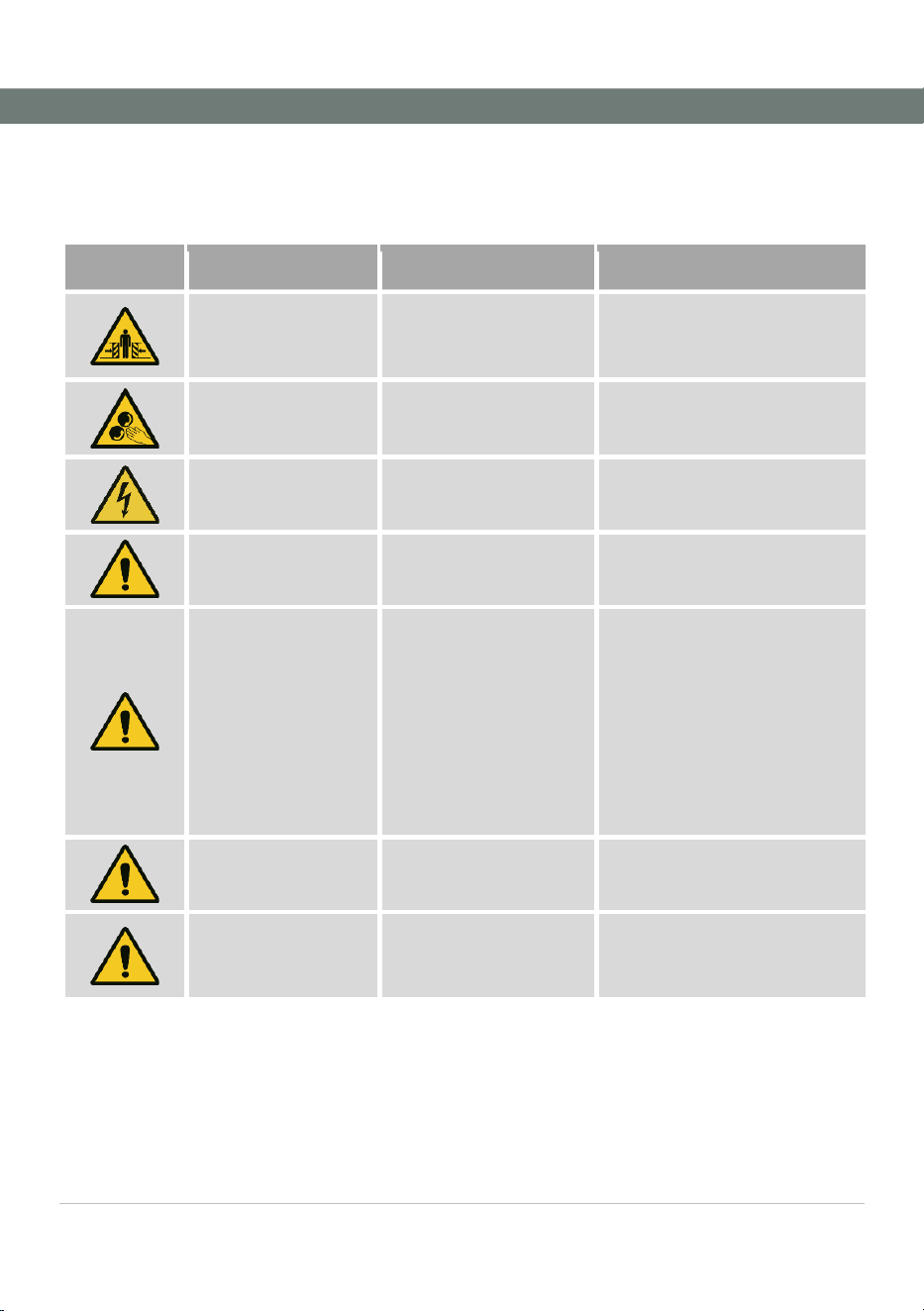
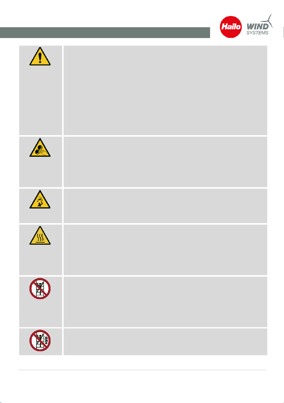
3.1 Residual risks
List of the residual risks
This list includes the remaining machine hazards and the actions you
must take to minimize the risk of personal injury or property damage:
Symbol
Danger point
Danger
Measure
Starting area of the
access platform at the
starting level
Impact by access platform
Keep a safe distance from
starting area; keep out of travel
route
Feeding ropes into the
rope hoist
Crushing / pulling in
Use extra caution when
threading in ropes
Control cabinet
Electric shock
Only specialist personnel may
work on the control cabinet
Access platform
Defective or disabled
safety devices
Check before commencing travel
Access platform
Impacts / shearing
▪ Stand correctly on the
tread plates
▪ Keep your arms by
your body when the
apparatus is moving!
▪ Do not lean back or to
the side!
▪ Watch the travel path
Access platform
Collision
Always remove fall arresters from
the fall protection rail.
On the ladder
Impacts / shearing
There must be no persons on the
access ladder when the C-lift is
operating.

Safety
Operating instructions · C-Lift Guard
V01R02 · · 2026-03
9
3.2 FCC Compliance
Contains:
FCC ID: 2BR8Y-CLIFTUSA-V00
IC: 34928-CLIFTUSAV00,
HVIN: 001
This device complies with part 15 of the FCC Rules. Operation is subject
to the following two conditions:
(1) This device may not cause harmful interference, and
(2) this device must accept any interference received, including
interference that may cause undesired operation.
Statement as per FCC15.105(a):
Note: This equipment has been tested and found to comply with the
limits for a Class A digital device, pursuant to part 15 of the FCC Rules.
These limits are designed to provide reasonable protection against
harmful interference when the equipment is operated in a commercial
environment. This equipment generates, uses, and can radiate radio
frequency energy and, if not installed and used in accordance with the
instruction manual, may cause harmful interference to radio
communications. Operation of this equipment in a residential area is
likely to cause harmful interference in which case the user will be
required to correct the interference at his own expense.
FCC RF Exposure Information
This device complies with FCC RF exposure requirements. Based on the
maximum transmitted output power, this device qualifies for exemption
from routine RF exposure evaluation in accordance with 47 CFR §
1.1307(b)(3)(i)(A). Therefore, no minimum separation distance is
required for RF exposure compliance.
3.3 ISED Canada Compliance
CAUTION
Any modification or change not expressly approved by the party
responsible for compliance could void the user's authority to
operate this equipment.
The licence-exempt transmitter/receiver contained in this apparatus
complies with Innovation, Science and Economic Development
Canada's NRC standards applicable to licence-exempt radio devices.
Operation is authorised subject to the following two conditions:
1. The device must not cause interference;
2. Operation is subject to the following conditions: this device may not
cause interference, regardless of the level of interference received.
Radio Frequency (RF) Exposure: This equipment complies with ISED
RF exposure limits for an uncontrolled environment.
Safety
Operating instructions · C-Lift Guard
V01R02 · · 2026-03
10
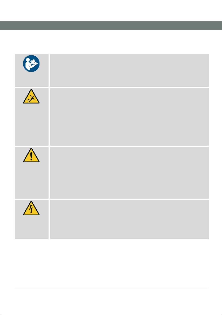
3.4 Safety instructions
Personal injury and property damage are possible due to non-compliance
with safety regulations.
▪ The instructions must be read carefully before assembly and use.
▪ Observe the safety regulations for wind turbines and the instructions
from the system manufacturer.
DANGER!
When working at heights, there is a risk of injury from falling.
▪ Before using and installing the machine, always secure yourself with the
personal fall protection equipment (PFPE).
▪ Do not use the access platform if you feel unwell or are in poor physical
condition.
▪ When using the access platform, two persons must always be present in
the wind turbine. Everyone must be able to make an emergency call at
any time.
DANGER
Risk of injury due to improper operation
▪ Never modify, remove or circumvent the safety equipment or parts of it!
▪ Do not exceed the working load limit of 140 kg (user weight including
PPE).
▪ Note the wind speed. The maximum permissible wind speed for using
the access platform can be found in the documentation of the wind
turbine operator.
DANGER
There is an electric voltage of 230 V. Danger to life from electric shock!
▪ The fixed ladder must be grounded along its entire length (equipotential
bonding).
▪ Only specially trained personnel may work on the electrical circuit of the
machine.
Safety
Operating instructions · C-Lift Guard
V01R02 · · 2026-03
11
DANGER!
Danger of falling due to damaged components
▪ The access platform may only be used if it is in perfect condition.
Operation with defective or incorrectly adjusted parts can endanger
personnel and/or the access platform.
▪ Damage or irregularities on the access platform must be reported to the
manufacturer and the system operator immediately.
▪ Only original Hailo Wind Systems parts may be used for installation,
maintenance or repairs. The access platform may not be modified or
expanded without the prior written consent of the manufacturer.
▪ Observe the maintenance intervals.
WARNING
Risk of injury from being pulled in by the ropes
▪ During operation of the access platform, the circulating ropes are in
motion. Do not reach into cable guides, cable pulleys or areas that are
not visible.
▪ Be sure to secure loose details on your work clothing appropriately.
WARNING
Risk of injury from falling objects.
▪ Only transport objects to higher platforms in approved containers. Tools
must be securely attached to the work harness.
WARNING
Risk of burns from heated surfaces during operation!
▪ With longer running times there is a risk of burns when touching the
surfaces of the drive unit.
▪ Do not touch the drive unit (motor and gearbox) until they have cooled
down.
WARNING
Do not use the ladder when the access platform is in use.
▪ During operation of the access platform, the circulating ropes are in
motion and endanger people who are on the ladder.
▪ Before using the access platform, check whether the ladder is free. Keep
an eye on the fixed ladder while driving.
WARNING
Do not use the access platform in the event of a fire!

Safety
Operating instructions · C-Lift Guard
V01R02 · · 2026-03
12
Put on personal fall protection equipment (PFPE)
▪ Use an approved fall protection system and personal fall
protection equipment (PPE).
▪ The personal fall protection equipment (PFPE) must be checked every
working day to ensure that it is in perfect and safe condition. The safety
of the user depends on the effectiveness of their equipment.
▪ The personal fall protection equipment must be properly selected, used
and checked.
Carry along a communication device (mobile phone, radio unit)
▪ When in or on the wind turbine generator, constant voice contact must
be ensured between the people involved.
Wear a helmet
Wear safety footwear
Wear safety gloves
Wear safety glasses
Safety
Operating instructions · C-Lift Guard
V01R02 · · 2026-03
13
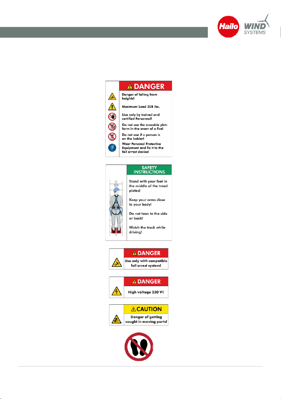
3.5 Markings on the access platform
Markings and safety
instructions
Do not remove any markings and regularly check their legibility.
Safety regulations access
platform
Above the actuators
Operating instructions
Above the actuators
Control panel access
platform
On the top of the switch-off plate
at the top
Warning electrical voltage
On the control
Warning of being pulled in
On the rope hoist, rope deflector at
the top and tensioning unit at the
bottom
Entering the area prohibited
On the rope hoist and on the
control cabinet

Safety
Operating instructions · C-Lift Guard
V01R02 · · 2026-03
14
Grounding point indication
3.6 Type plates
Type plate access platform
On the front of the access platform
Type plate rope hoist
On the rope hoist
Rope data tag

Technical Data
Operating instructions · C-Lift Guard
V01R02 · · 2026-03
15
4 Technical Data
Drive unit
Power
1.1 kW
Voltage
230 V 3Ph
Frequency
60 Hz
Weight
74,5 lbs (33.8 kg)
Rope interval between bearing ropes
150 mm
Working Load Limit
308 lbs (140 kg)
Access platform
Travel speed of the access platform
18 m/min & 9 m/min
Weight
77 lbs (35 kg)
Max. travel route height
130 m
Control
Voltage
230 V 1Ph
Frequency
60 Hz
Bearing rope
Manufacturer
DWH
Type
6 x 19S-SFC sZ, galv. zink coated
Diameter
6 mm
Breaking load
26.75 kN
Rope strength class
1960
Ambient conditions
Temperature range
-20°C to 50°C
Design and function
Operating instructions · C-Lift Guard
V01R02 · · 2026-03
16
5 Design and function
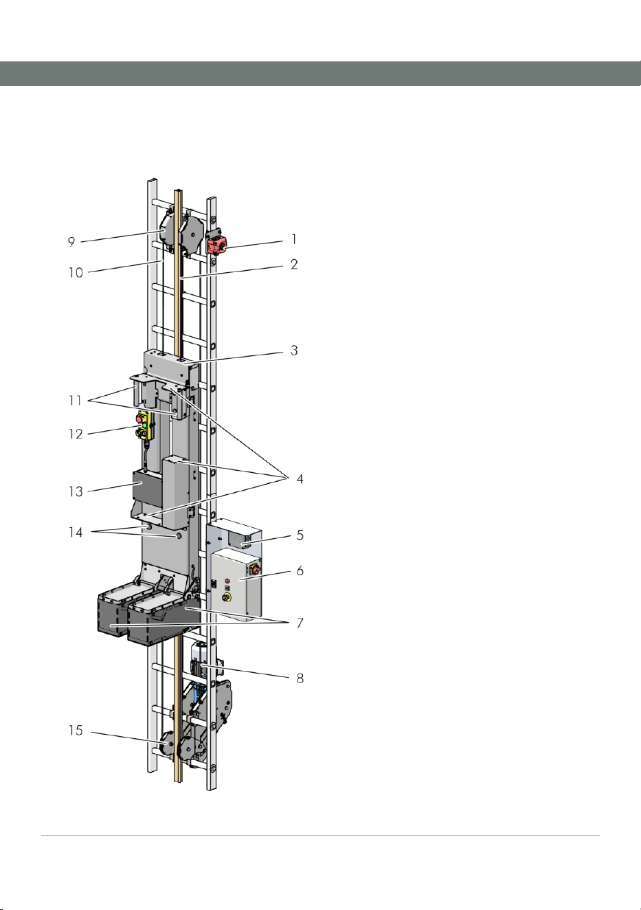
5.1 Main components of the access platform
Fig. 1: Main components system
1 Horn for start-up warning signal
2 Fall protection rail
3 Switch-off plate at the top
4 Tread plates for evacuation
5 Radio receiver
6 Control
7 Tread plates and safety switch-off at the
bottom
8 Drive unit
9 Rope deflector at top
10 Rope
11 Actuator / Two-hand operation
12 Control panel on access platform
13 Radio transmitter and LED display
14 Locking magnets
15 Bottom rope deflector and tensioning
unit
Design and function
Operating instructions · C-Lift Guard
V01R02 · · 2026-03
17
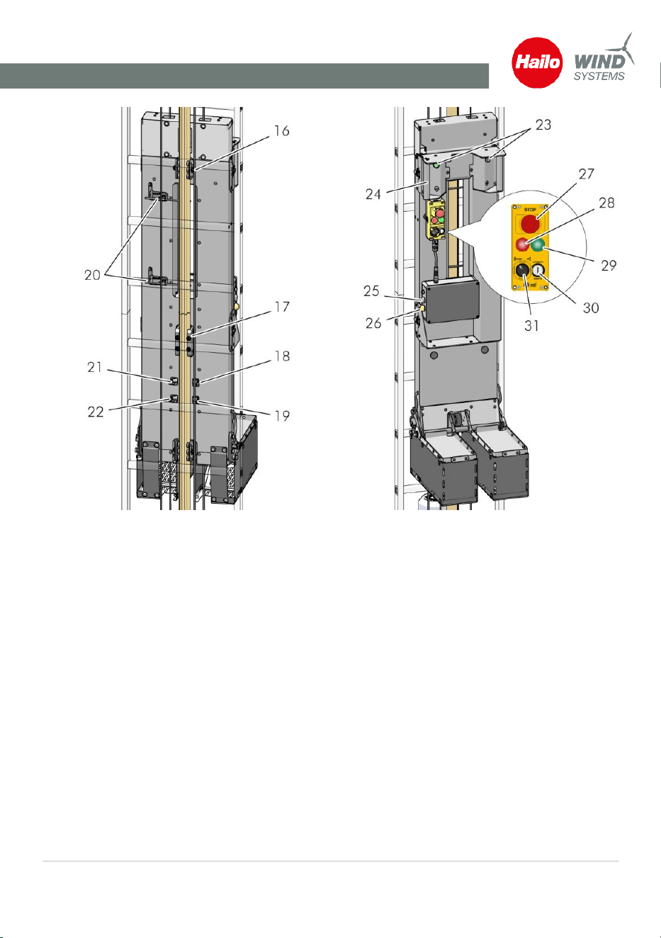
Fig. 2: Rear side of access platform
Fig. 3: Front side of access platform
16 Slider on the fall protection rail
17 Fall arrester
18 Button for platform stop
19 Speed regulator at platform
20 Safety switch-off for the slider
21 Switch for end of travel at top
22 Switch for end of travel at bottom
23 Actuator of two-hand operation
24 Handle
25 Output beeper
26 Signal light
27 Emergency stop button
28 Red light on the transmitter
29 Green light Ready for operation
30 Selector switch up/down travel
31 Button automatic travel / remote
Design and function
Operating instructions · C-Lift Guard
V01R02 · · 2026-03
18
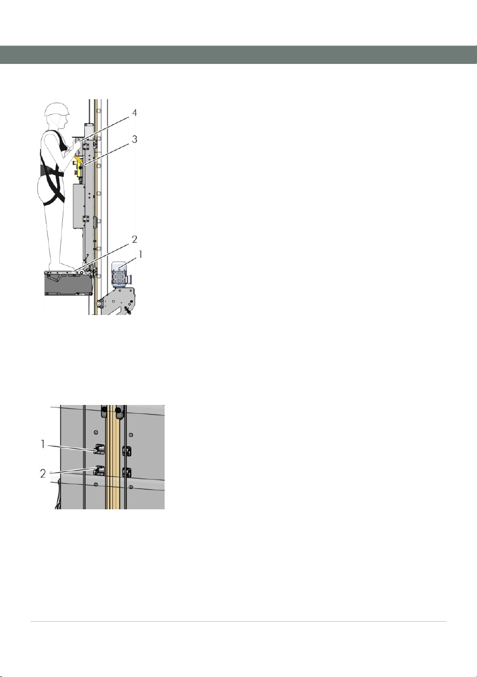
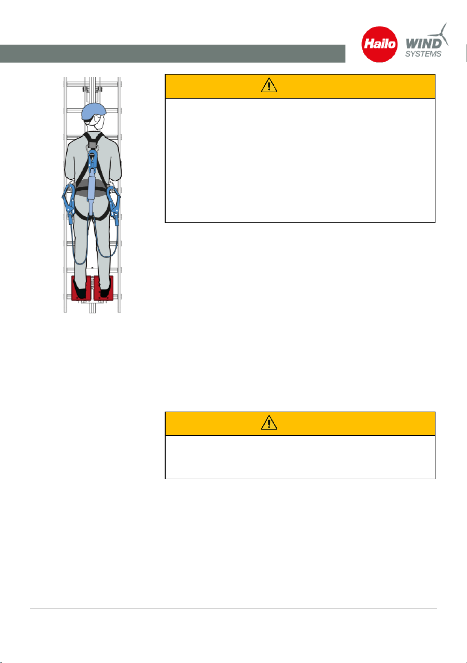
5.2 Function of the access platform
Fig. 4: User on the access
platform
The access platform C-Lift Guard facilitates the ascent on a fixed ladder.
The access platform is permanently installed on the fixed ladder.
The drive unit [1] is bolted to the fall protection rail and has an
electromagnetic service brake that closes automatically.
The access platform is driven by 2 bearing ropes and is guided by guide
rollers on the fall protection rail. The upper rope deflector is installed
above the fall protection rail.
The user of the access platform climbs onto the tread plates [2] of the
access platform and secures himself with his personal protective
equipment against falls from a height (PPEgA) and a fall arrester [3] on
the climbing protection rail of the access ladder. The access platform is
started by pressing the actuators simultaneously and continuously. When
the actuators [4] are released, the access platform stops.
5.3 Travel limiters
Travel limiters
Fig. 5: Travel limiters
There are roller switches on the back of the access platform for
switching off the access platform at the end of the travel path.
At the upper end of the travel path, the access platform is stopped
by approaching the roller switch [1]. At the lower end of the travel
path, the access platform is stopped by approaching the roller
switch [2].
1 Roller switch travel path limiter at the top
2 Roller switch travel path limiter at the bottom
Design and function
Operating instructions · C-Lift Guard
V01R02 · · 2026-03
19
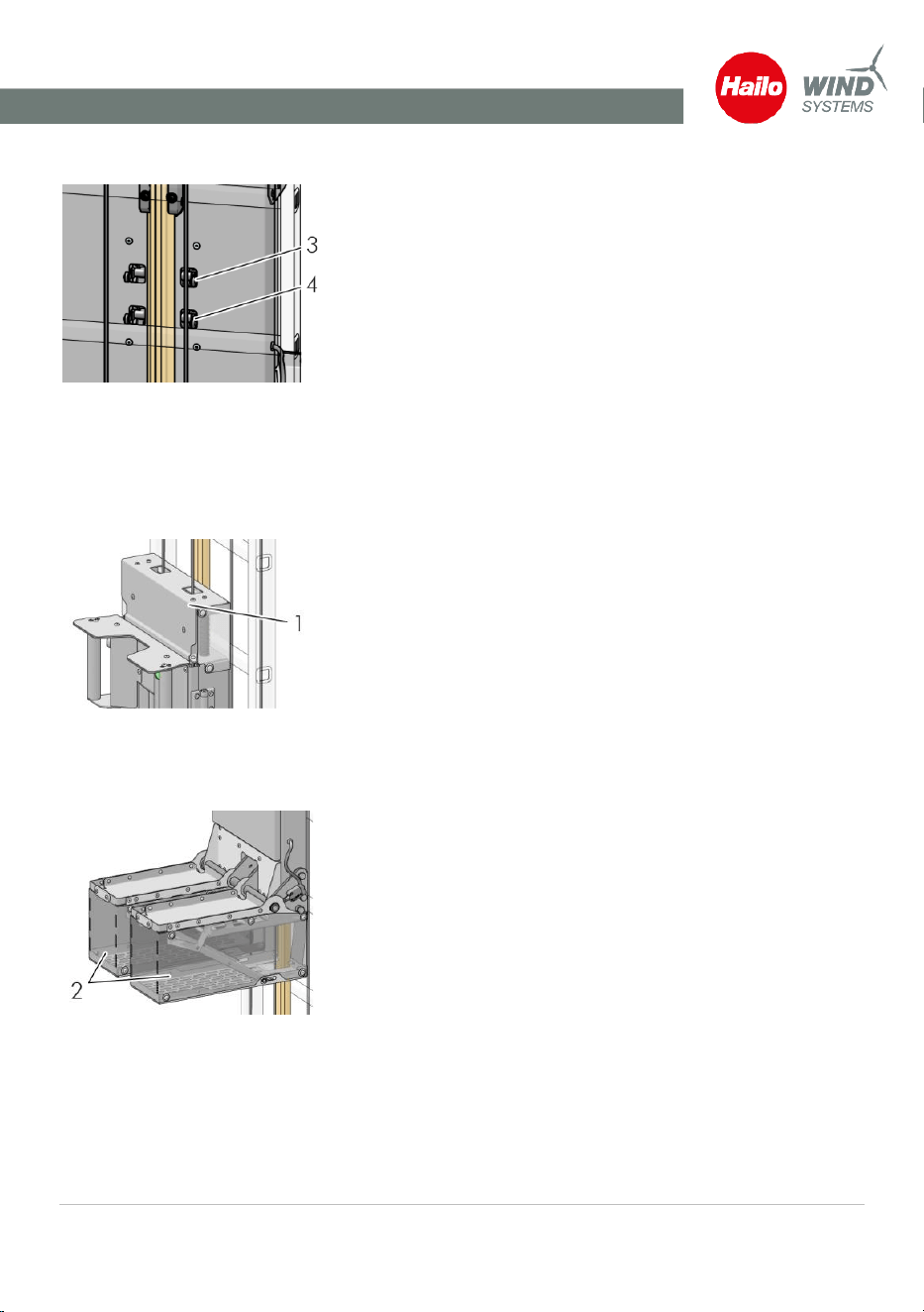
Reduced speed at platform
Fig. 6: Speed switch
A roller switch on the rear of the access platform is activated when
approaching a platform and reduces the speed to 9 m/min while
passing through the platform. Above the platform, the speed
increases again to 18 m/min.
In manual operation, the access platform also stops at each
platform. The platform stop switch [4] is activated for this purpose.
3 Speed regulator
4 Roller switch platform stop
5.4 Safety switch-offs
Switch-off plate at the top
Fig. 7: Switch-off plate at the top
A switch-off plate at the top [1] serves as a safety switch-off for the
access platform during upward travel. If there is an obstacle on the
fixed ladder, the access platform is stopped by actuating the
switch-off plate.
1 Switch-off plate at the top
Switch-off plate at the bottom
Fig. 8: Switch-off plate at the
bottom
Two switch-off plates [2] underneath the treads serve as a safety
switch-off of the access platform during downward travel. If there is
an obstacle on the fixed ladder, the access platform is stopped by
actuating the switch-off plates.
2 Switch-off plate at the bottom
Design and function
Operating instructions · C-Lift Guard
V01R02 · · 2026-03
20
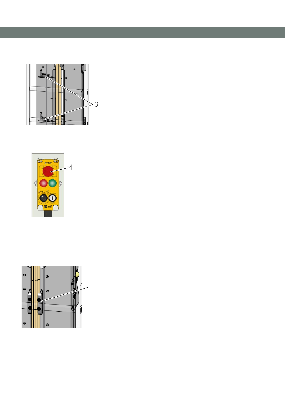
Safety switch-offs for the
slider
Fig. 9: Safety switch-off for slider
Two rod switches [3] prevent the access platform from moving if
the personal protective equipment slider cannot move along the
fall arrest rail.
3 Safety shutdown for slider on the fall arrest rail
Emergency stop function
Fig. 10: Emergency stop button
on the control panel
The emergency stop function is used to stop the access platform
(e.g. in case of danger). The emergency stop button [4] is located
on the control panel of the access platform.
A second emergency stop button is located on the receiver of the
control unit.
4 Emergency stop button
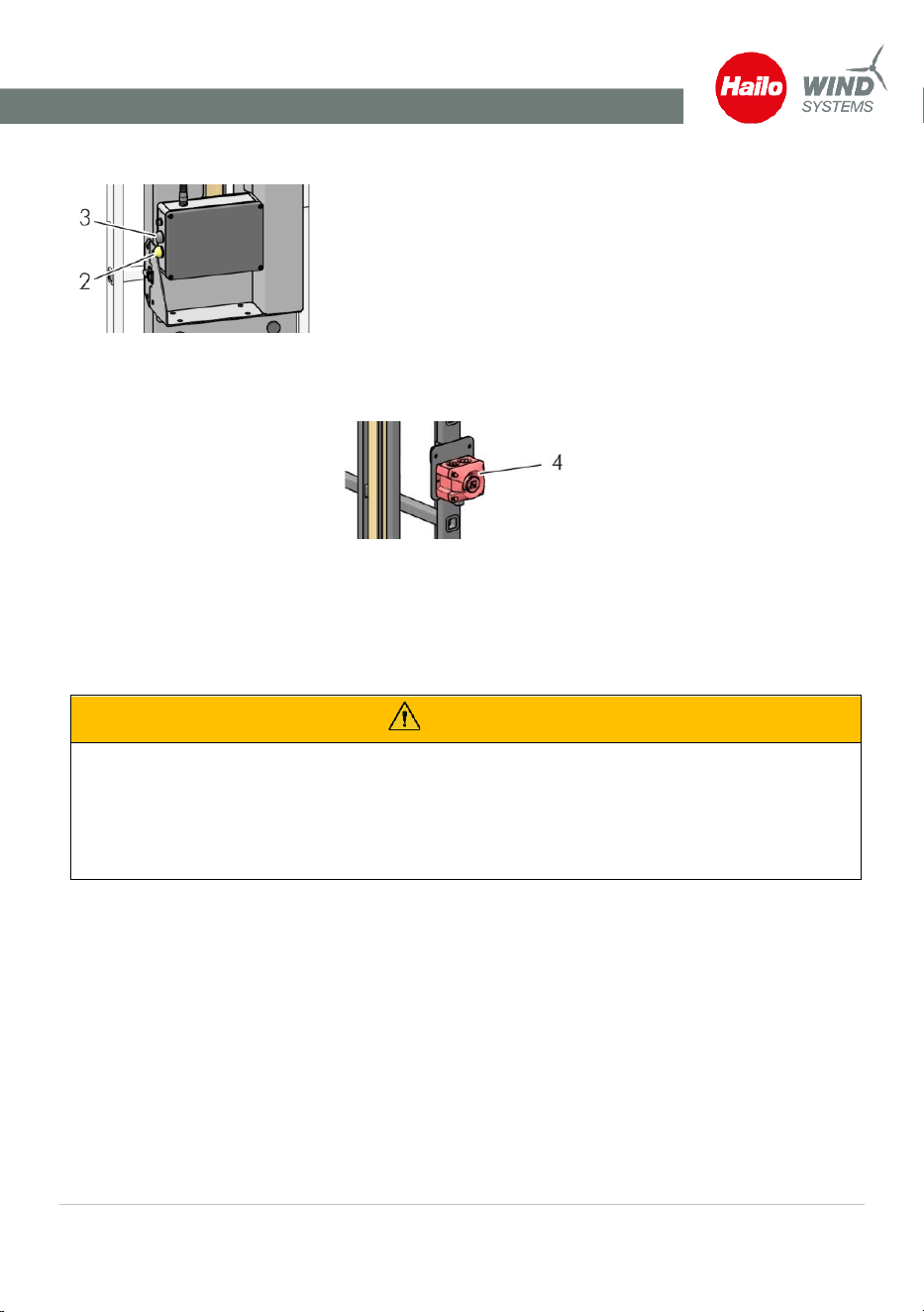
5.5 Other safety devices
Fall arresters
Fig. 11: Fall arrester
The following components protect against falling:
▪ Fall arrester on the access platform [1]: Stops the access
platform in the event of overspeed. In this case, the
access platform is held by a locking mechanism on the
fall protection rail.
▪ Guided fall arrester of the user as part of the personal
protective equipment against falls. The fall arrester is
held on the fall protection rail as soon as it is pulled
down (fall protection).
Operation
Operating instructions · C-Lift Guard
V01R02 · · 2026-03
21
Warning signals
Fig. 12: Warning signals
▪ Signal light [2] flashes when the access platform is in
operation. Warns other persons in the wind turbine not
to use the fixed ladder.
▪ Loudspeaker [3] gives a regular beep when approaching
a platform, during platform passage and during
automatic travel.
▪ A signal horn [4] at the top of the fixed ladder emit a 3-
second warning tone before the access platform is
started. Other persons in the wind turbine are requested
to move away from the fixed ladder at the latest when
this signal is given.
Fig. 13: Signal horn on fixed ladder
6 Operation
6.1 Workday preparation – Daily Check
WARNING
There is a risk of fatal injury if the safety equipment is defective.
▪ An inspection of the access platform must be performed before the first daily use (daily
check).
▪ If the inspection is not passed, the access platform must not be used until the defects
have been rectified.
Visual inspection of the access platform and the ropes
1. ► Check the attachment of the drive unit and the rope
tensioning unit at the bottom of the ladder.
2. ► Check whether the charging cable was plugged in. Unplug
it for use.
3. ► Check the bearing ropes for damage (broken wires, etc.).
Operation
Operating instructions · C-Lift Guard
V01R02 · · 2026-03
22
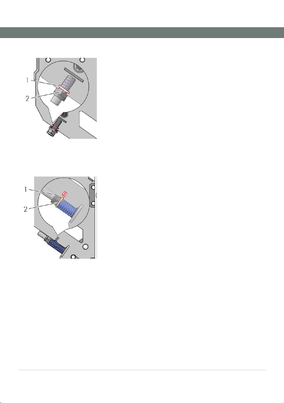
Check the spring tension of the rope pressure pulley
Fig. 14: Checking spring
tension
1. ► Check the spring tension of the rope pressure pulley by
looking straight into the viewing window [1].
⇨ The spring should be tensioned so that the washer [2]
is level with the viewing window [1].
⇨ If the washer is not level with the viewing window,
adjust the spring tension by tightening or loosening
the nut until the visual inspection is positive.
2. ► If necessary, adjust the springs on both sides until both
washers indicate the correct spring tension.
Check the rope tension
Fig. 15: Checking rope tension
1. ► Check the rope tension by looking straight into the
viewing window [1] at the height of the rope tensioning
unit.
⇨ The cables should be tensioned so that the washer [2]
is visible in the viewing window [1] or the recess on the
edge when you look straight at it.
⇨ If the washer is not at the height of the viewing
window, adjust the spring tension by tightening or
loosening the nut until the visual inspection is positive.
2. ► If necessary, make the adjustment for both cables until
both washers indicate the correct cable tension.
Documentation Daily Check in the logbook
1. ► Enter the results of the Daily Check in detail in the
logbook.
2. ► Enter the name and company of the inspector. With
your signature you confirm the correct execution
and the result of the Daily Check.

Operation
Operating instructions · C-Lift Guard
V01R02 · · 2026-03
23
6.2 Control panel on the access platform
Emergency stop button
Stops the access platform when pressed. Pull the button out again if
the access platform is to be restarted, otherwise start-up is
prevented.
Control lamps operational readiness
Green lamp lights up: Access platform ready for operation.
Red lamp lights up: Access platform not ready for operation. See
"Troubleshooting".
Red lamp flashes and signal tone: Overload shutdown has been
triggered.
Selector switch direction of travel
Position left: Downward travel
Position right: Upward travel
Button for automatic travel and remote operation
Control panel connected to standard cable: Press and hold button
for 3 seconds to start automatic travel.
Spiral cable has been connected: Pressed button starts travel in
remote mode.
6.3 Control cabinet
Main switch (emergency stop switch)
Located on the control cabinet. Switches the mains voltage of the
access platform on or off. The switch can be secured with a lock to
prevent unauthorized switching on.
Emergency Stop button
Stops the access platform when pressed. Pull the button out again
when you want to start the access platform, otherwise it will prevent
it from moving.
Red indicator light
Lights up or flashes when an error occurs and the access platform
cannot move. Refer to the "Troubleshooting" chapter.
Operation
Operating instructions · C-Lift Guard
V01R02 · · 2026-03
24
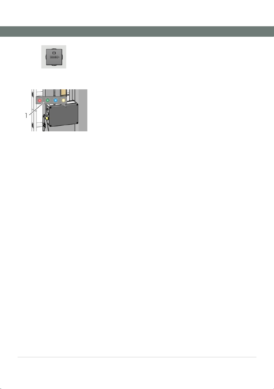
Operating hours counter
Shows the operating hours of the drive unit to date.
6.4 LED display on the transmitter
Fig. 16: LED display on the
transmitter
The LED display [1] on the transmitter provides the following
information:
Red lamp lights up: Access platform not ready for operation. See
"Troubleshooting".
Green lamp lights up: Access platform ready for operation.
Blue lamp flashes: Charging cable connected. Access platform not
ready for operation.
White lamp lights up: during automatic travel.
Operation
Operating instructions · C-Lift Guard
V01R02 · · 2026-03
25
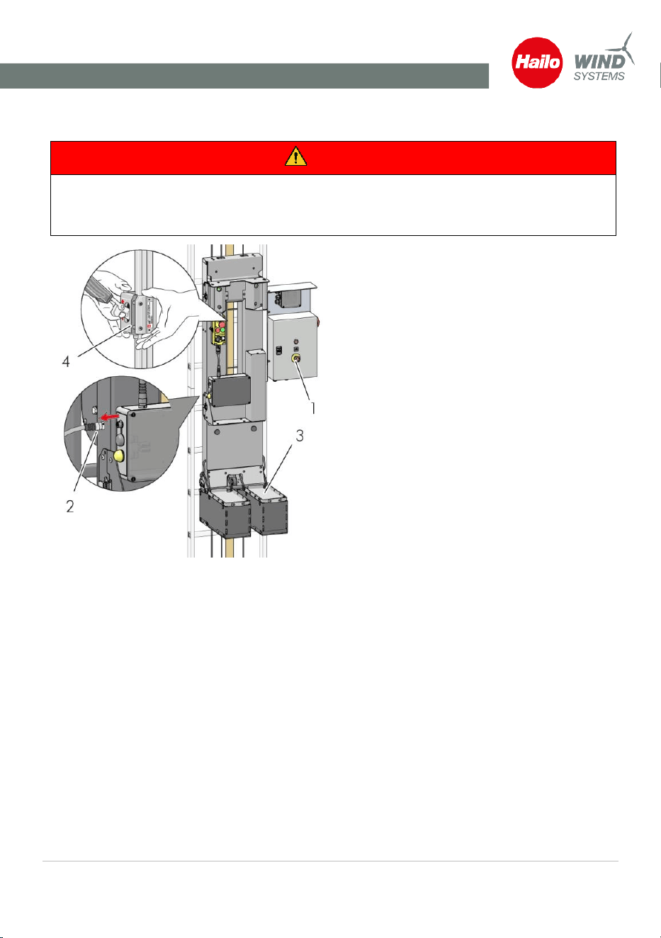
6.5 Passenger operation with the access platform
DANGER
Danger to life from falling!
Always secure yourself with a suitable fall arrester on the arrester rail before using the climbing
platform!
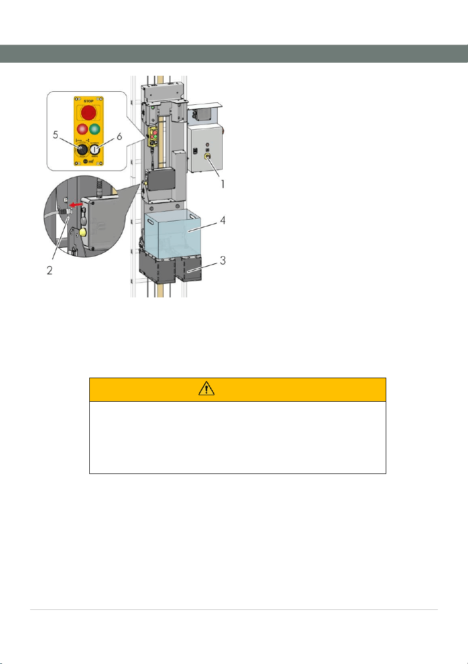
Fig. 17: Establish operational readiness
1 Main switch
2 Unplug charging cable
3 Unfold tread plates
4 Insert fall arerster into fall arrester rail
1. ► Check whether your Personal Protective Equipment against falls from a height is correctly
donned and complete.
2. ► Make the device ready for operation by disconnecting the charging cable [2].
3. ► Fold up the treads [3] completely. Stand on the tread surfaces.
4. ► Secure yourself to the arrester rail with the fall arrester [4].
Operation
Operating instructions · C-Lift Guard
V01R02 · · 2026-03
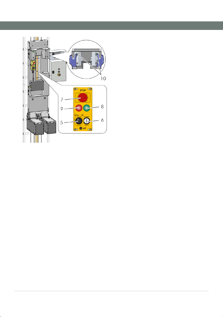
26
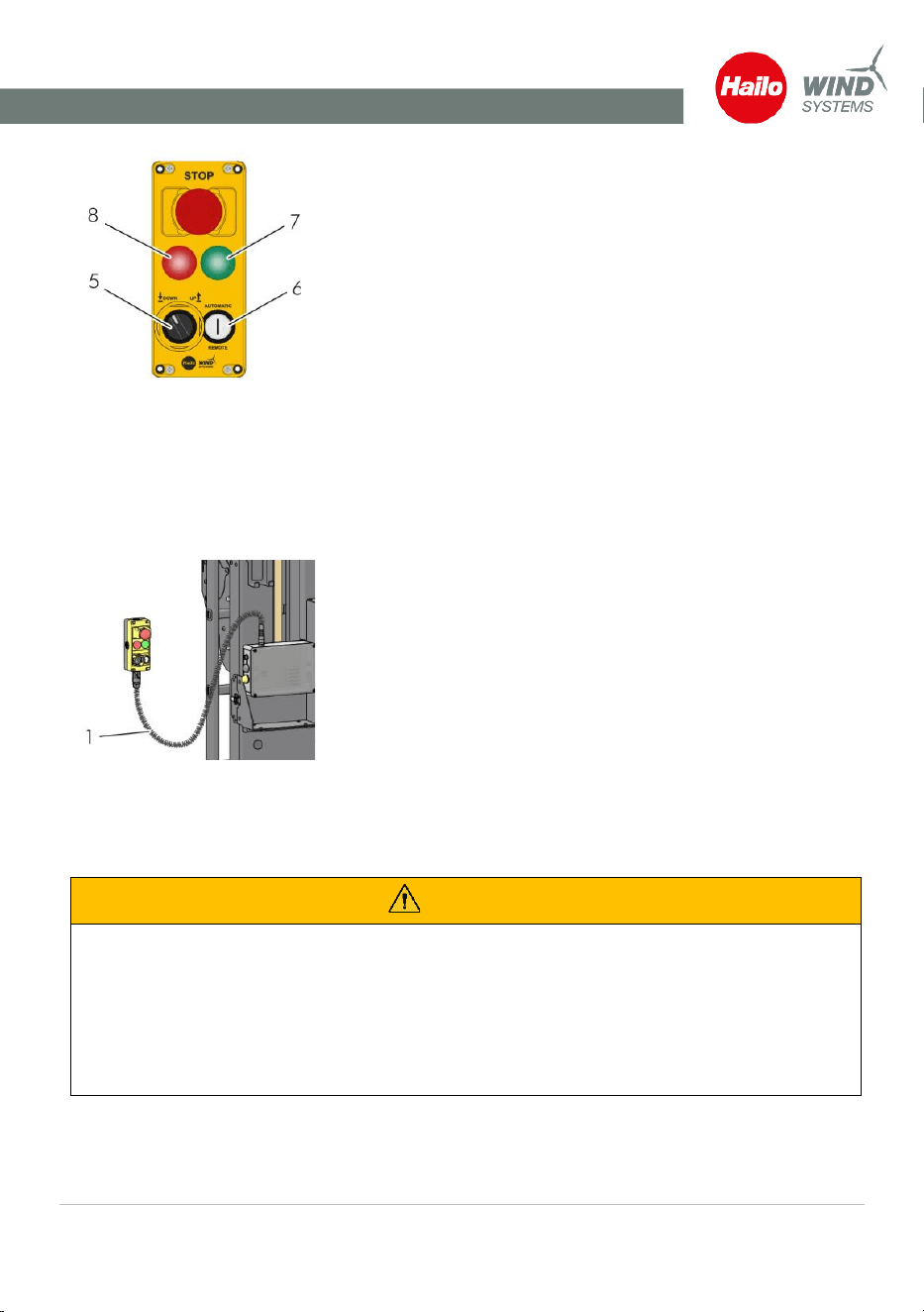
Fig. 18: Prepare and start ride
5 Travel direction selector switch
6 Button automatic travel
7 Emergency stop button must not be
actuated
8 Green light: Ready for operation
established
9 Red light: Not ready for operation
10 Press the actuators simultaneously to start
the travel
1. ► Set the direction of travel on the selector switch [5]. Make sure that no emergency stop
button [7] is pressed.
⇨ The platform should be ready for operation: Green indicator [8] lights up.
⇨ Operational readiness not established: Red indicator [9] lights up. See chapter
"Troubleshooting".
2. ► Check whether the travel path is clear.
3. ► Press the actuators [10] on both sides simultaneously to start the travel.
⇨ The access platform stops as soon as one of the two actuators is released. To restart, both
actuators must be released and pressed again.
Operation
Operating instructions · C-Lift Guard
V01R02 · · 2026-03
27
Fig. 19: Operator in correct
posture
WARNING
Risk of injury due to incorrect behavior!
▪ Stand firmly on the designated position on the tread
plates!
▪ Do not lean outwards and avoid uncontrolled
movements!
▪ Keep your arms close to your body!
▪ Be especially careful when passing through the
platforms!
▪ Observe the travel path during the ride!
6.6 Automatic travel and material transport
Automatic travel of the
access platform
The access platform can be sent to the start or destination platform
with automatic travel. The automatic mode is used exclusively for
material transport or to perform an empty run!
WARNING
Risk of injury due to inadequate safety precautions!
▪ The automatic mode must not be used for transporting
persons.
Operation
Operating instructions · C-Lift Guard
V01R02 · · 2026-03
28
Fig. 20: Establish operational readiness
1 Main switch
2 Unplug charging cable
3 Unfold tread plates
4 Insert transport box
1. ► Make the device ready for operation by disconnecting the charging cable [2].
2. ► Fold up the treads [3] completely. Hang the transport box [4] in the holder provided.
⇨ The automatic travel can only be started when the transport box is correctly fastened.
3. ► Load the transport box, if required.
WARNING
Risk of injury due to inadequate safety precautions!
▪ The maximum permissible payload must not be exceeded.
▪ Make sure that the load does not overhang the basket and
that no parts can fall through the grab handles.
▪ Position the load so that it cannot fall over.
Operation
Operating instructions · C-Lift Guard
V01R02 · · 2026-03
29
Fig. 21: Control panel
4. ► Set the direction of travel on the selector switch [5].
⇨ Operational readiness should be established: Green
display [7] lights up.
⇨ Operational readiness not established: Red display [8]
lights up. See chapter "Troubleshooting".
5. ► Check whether the travel path is clear.
6. ► Press and hold the Automatic travel button [6] for 3 seconds.
⇨ Automatic travel is stopped at the end of the travel path
by the travel path limitation.
6.7 Remote operation with the operating panel
The access platform can be controlled remotely from the ladder via a cable extension of the control
panel. The spiral cable can be extended to a length of 4 m.
Fig. 22: Connect spiral cable
1. ► Disconnect the connection cable between the
control panel and the transmitter. Remove the
control panel from its holder.
2. ► Open the door of the access platform, remove the
spiral cable.
3. ► Plug the spiral cable [1] into the control panel and
transmitter.
⇨ The automatic mode and manual mode are
now deactivated.
4. ► Set the travel direction on the operating panel using the travel direction selector
switch.
5. ► Check whether the travel path is free. Press the Remote button to start the travel.
WARNING
Risk of injury due to incorrect behavior!
▪ When using the fixed ladder, secure yourself with a suitable fall arrester on the arrester
rail.
▪ Be especially careful when passing through the platforms!
▪ The remote operation must not be used for transporting persons.
▪ Observe the travel path during travel!

Operation
Operating instructions · C-Lift Guard
V01R02 · · 2026-03
30
6.8 Exiting the access platform
DANGER
Danger to life from falling!
▪ Secure yourself at a suitable anchor point before
disconnecting the fall arrester from the fall protection rail
End ride
1. ► Move with the actuators pressed until the access platform
stops automatically at the platform. Only then release the
actuators.
2. ► Secure yourself at a suitable anchor point on the platform.
3. ► Disconnect the fall arrester from the fall protection rail.
4. ► Climb from the tread plates onto the platform.
After working day use of the
access platform
1. ► Press the emergency stop button when the access platform
stops at the launch platform.
2. ► Disconnect the fall arrester from the fall protection rail and step
off the access platform.
3. ► Fold up the tread plates.
4. ► Connect the charging cable to the transmitter.
⇨ The charging cable remains on the access platform until the
next time it is used. It does not need to be disconnected
from the transmitter even though the battery is full.
Evacuation from the access platform
Operating instructions · C-Lift Guard
V01R02 · · 2026-03
31
7 Evacuation from the access platform
In the event of a defect or emergency, exit the climbing platform as follows:
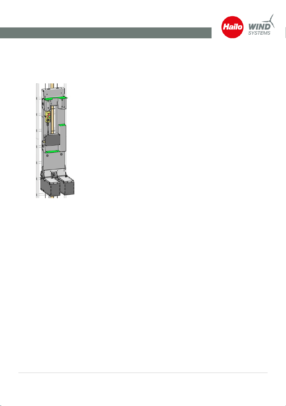
Evacuation upwards
Fig. 23: Steps (green) for
evacuation
1. ► Release the actuators on the access platform. Press the
emergency stop button on the control panel.
2. ► Secure yourself to the ladder rail or a suitable anchor point
with your personal protective equipment. Only then remove
the fall arrester from the fall protection rail.
⇨ Securing to a ladder rung is not permitted!
3. ► Step onto the provided treads (marked green) to climb up onto
the fixed ladder.
4. ► Secure yourself again with the fall arrester in the arrester rail.
Only then release your safety catch at the anchor point.
Evacuation downwards
1. ► Release the actuators on the access platform. Press the
emergency stop button on the control panel.
2. ► Secure yourself to the ladder rail or a suitable anchor point
with your personal protective equipment. Only then remove
the fall arrester from the fall protection rail.
⇨ Securing to a ladder rung is not permitted!
3. ► Climb onto a ladder rung below the access platform. If
possible, try to fold in the treads to allow safe standing on the
fixed ladder.
4. ► Secure yourself again with the fall arrester in the arrester rail.
Only then release your safety catch at the anchor point..

Troubleshooting
Operating instructions · C-Lift Guard
V01R02 · · 2026-03
32
8 Troubleshooting
8.1 Operational readiness
Check list operational
readiness
The access platform is ready for operation,
▪ when the charging cable has been disconnected from the
transmitter.
▪ when the two treads have been folded out.
▪ when the main switch on the control unit is switched on.
▪ when none of the emergency stop buttons are actuated.
▪ when a radio contact has been established between the
transmitter and receiver.
▪ if none of the switches for travel path limitation or safety
shutdown has been triggered.
▪ if there is no overload on the access platform.
▪ if the centrifugal brake of the climbing platform has not been
triggered.
Indication of operational readiness: Green signal light and the green
LED on the transmitter light up.
8.2 Error indications
Display
Error description
Remedy
Access platform stops after radio
interruption.
After a radio interruption, the start
command must be given again.
▪ Check for possible obstacles in
the radio range.
▪ Release both actuators.
▪ Press both actuators
simultaneously.
Access platform does not move off in
manual mode.
Check whether the following points prevent
the device from being ready for operation:
▪ Charging cable plugged in.
▪ Remote cable connected.
▪ Emergency stop button actuated
(on the access platform or on the
control unit).
▪ Travel path limitation or safety
shutdown triggered.
▪ Centrifugal brake triggered.

Troubleshooting
Operating instructions · C-Lift Guard
V01R02 · · 2026-03
33
Display
Error description
Remedy
▪ Overload triggered.
▪ Treads not folded out correctly.
▪ Tread surfaces unevenly loaded.
▪ The slider has become stuck on
the fall arrest rail and is located in
the critical area where the rod
switch at the top or bottom has
been triggered (reserve safety
device).
Access platform does not move off in
automatic travel mode
▪ Send key not pressed long
enough (at least 3 sec.).
Access platform does not move off in
remote mode:
Check whether the following points prevent
the device from being ready for operation:
▪ Treads are not extended.
▪ Treads are loaded on the right or
left side. The treads must not be
loaded.
▪ Remote cable not plugged in.
▪ Send button not pressed.
The access platform stops or does not move.
A regular beep sounds.
▪ Overload on the access platform.
▪ Leave the access platform or
unload the transport crate until
the signal stops.

Troubleshooting
Operating instructions · C-Lift Guard
V01R02 · · 2026-03
34
8.3 Schedules and maintenance intervals
DANGER
Danger of injuries and death due to undiscovered defects on
the access platform
▪ The prescribed intervals for recurring inspections,
maintenance, and general overhauls must be observed.
▪ Inspections and maintenance must be carried out
according to the Hailo Wind Systems maintenance
schedule.
▪ Inspections, maintenance and general overhauls may only
be carried out by a person authorised, certified and
qualified by the manufacturer.
The following overview includes the maintenance intervals for the individual components:
Components
Every year
Inspection
and
maintenance
Every 5 years
Inspection
and
maintenance
After 10
years
General
overhaul
Personnel
Drive unit
Qualified person
Centrifugal brake
Qualified person
Ropes and rope deflector at the
top
Qualified person
Rope deflectors, cam, steps and
plate, distance rollers
Qualified person
Fixed access ladder
Qualified person
Control unit and control panels
Electrician
Documents
Qualified person
Battery replacement
Electrician
General overhaul after every 10 years
A scheduled general overhaul of the drive unit by the manufacturer is required after every 10 years at
the latest. In this case, please contact Hailo Wind Systems.
Daily Check – Logbook
Operating instructions · C-Lift Guard
V01R02 · · 2026-03
35
9 Daily Check – Logbook
Wind energy plant no.
C-lift serial number
Rope hoist serial number
Date
Comments
Name of the
inspector/company
Signature of
inspector

Daily Check – Logbook
Operating instructions · C-Lift Guard
V01R02 · · 2026-03
36
Date
Comments
Name of the
inspector/company
Signature of
inspector

Daily Check – Logbook
Operating instructions · C-Lift Guard
V01R02 · · 2026-03
37
Date
Comments
Name of the
inspector/company
Signature of
inspector

Daily Check – Logbook
Operating instructions · C-Lift Guard
V01R02 · · 2026-03
38
Date
Comments
Name of the
inspector/company
Signature of
inspector
Daily Check – Logbook
Operating instructions · C-Lift Guard
V01R02 · · 2026-03
39
Date
Comments
Name of the
inspector/company
Signature of
inspector

Daily Check – Logbook
Operating instructions · C-Lift Guard
V01R02 · · 2026-03
40
Date
Comments
Name of the
inspector/company
Signature of
inspector

Daily Check – Logbook
Operating instructions · C-Lift Guard
V01R02 · · 2026-03
41
Date
Comments
Name of the
inspector/company
Signature of
inspector
Daily Check – Logbook
Operating instructions · C-Lift Guard
V01R02 · · 2026-03
42
Date
Comments
Name of the
inspector/company
Signature of
inspector
Inspection plans
Operating instructions · C-Lift Guard
V01R02 · · 2026-03
43
10 Inspection plans
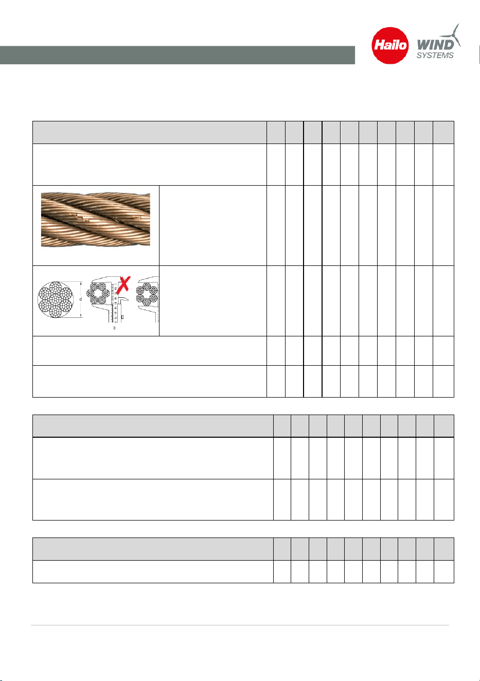
10.1 Annual inspection plan
Ropes
1
2
3
4
5
6
7
8
9
10
Rope inspection over the full travel route (caution: the
rope is subjected to different loads on both sides of the
ladder)
Check for wire cable
breaks.
If more than 2 wire
breaks occur over a
length of 50 mm: Rope
must be discarded
Check of the rope
diameter (min. Ø
5.8 mm)
Check the ladder and rope for friction points (retrofit
rung protectors, if applicable)
Lubricate the ropes, if necessary:
Use lubricants approved by the manufacturer
Rope deflectors
1
2
3
4
5
6
7
8
9
10
Rope deflector at TOP: Check that the rollers bearings run
smoothly, and that no unusual noises occur during
operation. The bearings must exhibit no play.
BOTTOM rope deflector: Check that the rollers bearings
run smoothly, and that no unusual noises occur during
operation. The bearings must exhibit no play.
Cam
1
2
3
4
5
6
7
8
9
10
Test the end position
Inspection plans
Operating instructions · C-Lift Guard
V01R02 · · 2026-03
44
Handles, tread plates
1
2
3
4
5
6
7
8
9
10
Bolted connection, function
Distance rollers
1
2
3
4
5
6
7
8
9
10
Check the distance rollers for free movement and
damage. The distance rollers must not show uneven or
excessive wear.
Fixed access ladder
1
2
3
4
5
6
7
8
9
10
Check according to manufacturer's instructions
Test run over the full travel route
1
2
3
4
5
6
7
8
9
10
Access platform released after completion of the test run
over the full travel route without defects.
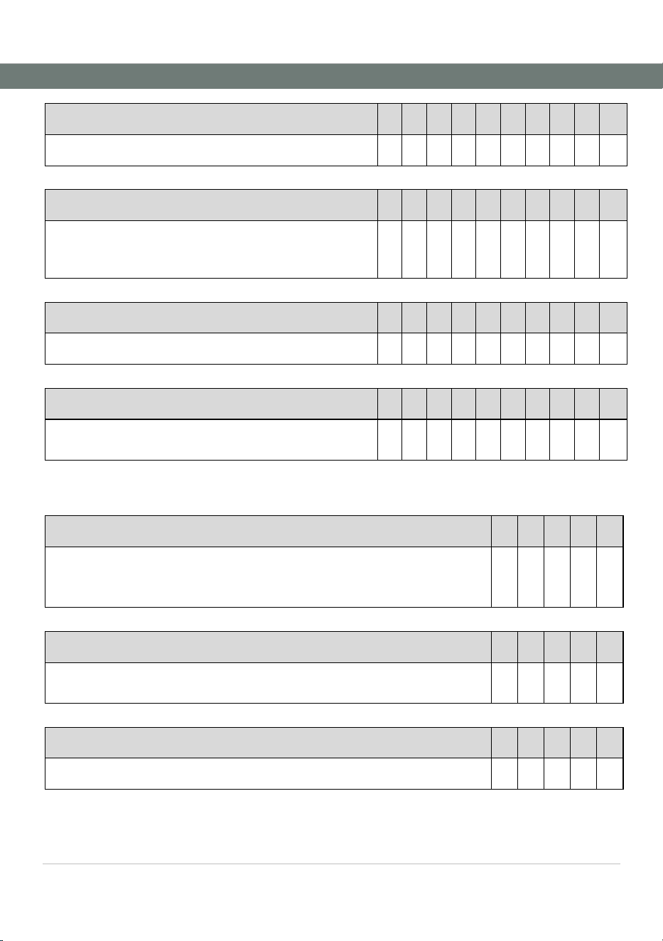
10.2 Inspection plan after 5 years
Drive unit
1
2
3
4
5
Check of the rope hoist for damage, oil loss, corrosion, dirt and missing parts,
unusual noises; legibility of the type plate.
A general overhaul by the manufacturer is required after every 10 years.
Centrifugal brake
1
2
3
4
5
Check the centrifugal brake for damage, contamination, and free movement.
If the test result is negative, a general overhaul is required.
Replacing the ropes
1
2
3
4
5
Both ropes must be replaced after 5 years.
Inspection plans
Operating instructions · C-Lift Guard
V01R02 · · 2026-03
45
Replacing the top rope deflector
1
2
3
4
5
The top rope deflector must be replaced after 5 years.
Control cabinet
1
2
3
4
5
Disconnect the control unit from the power supply. Confirm that the power
supply is off and secure it against being switched on again.
Check the control cabinet for damage, moisture, or water ingress. Check all
cable glands and plug connections.
Functional test of all control panels and drive functions.
Documents
1
2
3
4
5
Checking documents, safety labels and type plates for completeness and
legibility.
Replacing the battery
1
2
3
4
5
The battery must be replaced after 5 years.
Test drive over the full travel route
1
2
3
4
5
Access platform released after completion of the test run over the full travel
route without defects.

Inspection reports
Operating instructions · C-Lift Guard
V01R02 · · 2026-03
46
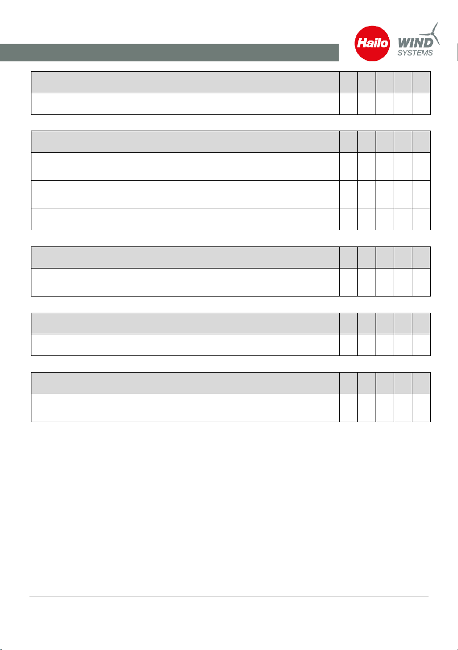
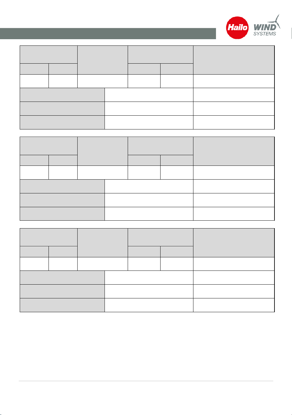
11 Inspection reports
Scheduled
inspection
Non-scheduled
inspection
Result
Result of rework
OK
1 Year
5 Years
OK
not OK
Place, date
Qualified assembler
If not OK: Required rework
Scheduled
inspection
Non-scheduled
inspection
Result
Result of rework
OK
1 Year
5 Years
OK
not OK
Place, date
Qualified assembler
If not OK: Required rework
Scheduled
inspection
Non-scheduled
inspection
Result
Result of rework
OK
1 Year
5 Years
OK
not OK
Place, date
Qualified assembler
If not OK: Required rework

Inspection reports
Operating instructions · C-Lift Guard
V01R02 · · 2026-03
47
Scheduled
inspection
Non-scheduled
inspection
Result
Result of rework
OK
1 Year
5 Years
OK
not OK
Place, date
Qualified assembler
If not OK: Required rework
Scheduled
inspection
Non-scheduled
inspection
Result
Result of rework
OK
1 Year
5 Years
OK
not OK
Place, date
Qualified assembler
If not OK: Required rework
Scheduled
inspection
Non-scheduled
inspection
Result
Result of rework
OK
1 Year
5 Years
OK
not OK
Place, date
Qualified assembler
If not OK: Required rework

Inspection reports
Operating instructions · C-Lift Guard
V01R02 · · 2026-03
48
Scheduled
inspection
Non-scheduled
inspection
Result
Result of rework
OK
1 Year
5 Years
OK
not OK
Place, date
Qualified assembler
If not OK: Required rework
Scheduled
inspection
Non-scheduled
inspection
Result
Result of rework
OK
1 Year
5 Years
OK
not OK
Place, date
Qualified assembler
If not OK: Required rework
Scheduled
inspection
Non-scheduled
inspection
Result
Result of rework
OK
1 Year
5 Years
OK
not OK
Place, date
Qualified assembler
If not OK: Required rework
Inspection reports
Operating instructions · C-Lift Guard
V01R02 · · 2026-03
49
Scheduled
inspection
Non-scheduled
inspection
Result
Result of rework
OK
1 Year
5 Years
OK
not OK
Place, date
Qualified assembler
If not OK: Required rework
Scheduled
inspection
Non-scheduled
inspection
Result
Result of rework
OK
1 Year
5 Years
OK
not OK
Place, date
Qualified assembler
If not OK: Required rework
Scheduled
inspection
Non-scheduled
inspection
Result
Result of rework
OK
1 Year
5 Years
OK
not OK
Place, date
Qualified assembler
If not OK: Required rework

Inspection reports
Operating instructions · C-Lift Guard
V01R02 · · 2026-03
50
Scheduled
inspection
Non-scheduled
inspection
Result
Result of rework
OK
1 Year
5 Years
OK
not OK
Place, date
Qualified assembler
If not OK: Required rework
Scheduled
inspection
Non-scheduled
inspection
Result
Result of rework
OK
1 Year
5 Years
OK
not OK
Place, date
Qualified assembler
If not OK: Required rework
Scheduled
inspection
Non-scheduled
inspection
Result
Result of rework
OK
1 Year
5 Years
OK
not OK
Place, date
Qualified assembler
If not OK: Required rework

Inspection reports
Operating instructions · C-Lift Guard
V01R02 · · 2026-03
51
Scheduled
inspection
Non-scheduled
inspection
Result
Result of rework
OK
1 Year
5 Years
OK
not OK
Place, date
Qualified assembler
If not OK: Required rework
Scheduled
inspection
Non-scheduled
inspection
Result
Result of rework
OK
1 Year
5 Years
OK
not OK
Place, date
Qualified assembler
If not OK: Required rework
Scheduled
inspection
Non-scheduled
inspection
Result
Result of rework
OK
1 Year
5 Years
OK
not OK
Place, date
Qualified assembler
If not OK: Required rework