
i
LAUNCH
Copyright Information
Copyright © 2023 by LAUNCH TECH CO., LTD. (also called LAUNCH for
short). All rights reserved. No part of this publication may be reproduced, stored
in a retrieval system, or transmitted in any form or by any means, electronic,
mechanical, photocopying and recording or otherwise, without the prior written
permission.
Statement: LAUNCH owns the complete intellectual property rights for the
software used by this product. For any reverse engineering or cracking actions
against the software, LAUNCH will block the use of this product and reserve the
right to pursue their legal liabilities.
Disclaimer of Warranties and Limitation of Liabilities
All information, illustrations, and specications in this manual are based on the
latest information available at the time of publication.
The right is reserved to make changes at any time without notice. We shall not
be liable for any direct, special, incidental, indirect damages or any economic
consequential damages (including the loss of prots) due to the use of the
document.

ii
LAUNCH
WARNING
Study, understand and follow all instructions provided with this product. Read
these instructions carefully before installing, operating, servicing or repairing
this tool. Keep these instructions in a safe, accessible place.
Caution: To help prevent personal injury,
• Never use this tool for any application other than for which it was
designed.
• Never alter or modify this tool in any way. Improper operation and / or
maintenance of the tool, or modication of the tool could result in serious
injury or death.
• Always perform automotive testing in a safe environment.
• Do not attempt to operate or observe the tool while driving a vehicle.
Operating or observing the tool will cause driver distraction and could
cause a fatal accident.
• Wear safety eye protection that meets ANSI standards.
• Keep clothing, hair, hands, tools, test equipment, etc. away from all
moving or hot engine parts.
• Operate the vehicle in a well-ventilated work area: Exhaust gases are
poisonous.
• Put blocks in front of the drive wheels and never leave the vehicle
unattended while running tests.
• Use extreme caution when working around the ignition coil, distributor
cap, ignition wires and spark plugs. These components create hazardous
voltages when the engine is running.
• Put the transmission in P (for A/T) or N (for M/T), and make sure the
parking brake is engaged.
• Keep a re extinguisher suitable for gasoline / chemical / electrical res
nearby.
• Don’t connect or disconnect any test equipment while the ignition is on or
the engine is running.
• Keep this tool dry, clean, free from oil / water or grease. Use a mild
detergent on a clean cloth to clean the outside of the tool, when necessary.

iii
LAUNCH
FCC STATEMENT
FCCID: XUJCREV20
Any Changes or modications not expressly approved by the party
responsible for compliance could void the user’s authority to operate the
equipment.
This device complies with part 15 of the FCC Rules. Operation is subject
to the following two conditions: (1) This device may not cause harmful
interference, and (2) this device must accept any interference received,
including interference that may cause undesired operation.
Note: This equipment has been tested and found to comply with the limits for
a Class B digital device, pursuant to Part 15 of the FCC Rules. These limits
are designed to provide reasonable protection against harmful interference in
a residential installation.
This equipment generates, uses, and can radiate radio frequency energy,
and if not installed and used in accordance with the instructions, may cause
harmful interference to radio communications. However, there is no guarantee
that interference will not occur in a particular installation. If this equipment
does cause harmful interference to radio or television reception, which can be
determined by turning the equipment o and on, the user is encouraged to try
to correct the interference by one or more of the following measures:
- Reorient or relocate the receiving antenna.
- Increase the separation between the equipment and receiver.
- Connect the equipment into an outlet on a circuit dierent from that to
which the receiver is connected.
- Consult the dealer or an experienced radio / TV technician for help.

iv
LAUNCH
Table of Contents
1. Introduction .................................................................................................... 1
1.1 Vehicle Coverage .......................................................................................... 1
1.2 On-Board Diagnostics (OBD) II ..................................................................... 2
1.3 OBD II Denitions .......................................................................................... 2
1.4 Diagnostic Trouble Codes (DTCs) ................................................................. 4
1.5 Location of the Data Link Connector (DLC)................................................... 5
2. Product Descriptions .................................................................................... 6
2.1 Components & Controls ................................................................................ 6
2.2 Technical Specications ................................................................................ 7
2.3 Accessories Checklist .................................................................................... 7
3. Initial Use........................................................................................................ 8
3.1 Powering Up The Tool ................................................................................... 8
3.2 Getting Started .............................................................................................. 8
3.3 Job Menu ....................................................................................................... 8
4. Diagnose ...................................................................................................... 10
4.1 Connection .................................................................................................. 10
4.2 System Diagnosing.......................................................................................11
4.2.1 Smart Diagnosis (Auto-Detect) .............................................................11
4.2.2 Manual Diagnosis ................................................................................ 12
4.3 OBD II Diagnosis ......................................................................................... 19
4.4 History ......................................................................................................... 20
5. Upgrade ........................................................................................................ 21
5.1 Update Diagnostic Software & App ............................................................. 21
5.2 Renew Subscription..................................................................................... 21
6. Mall................................................................................................................ 23
7. Settings ........................................................................................................ 24
7.1 Units of measurement ................................................................................. 24
7.2 Automatic detection on connect................................................................... 24
7.3 Brightness.................................................................................................... 24
7.4 Sound .......................................................................................................... 24
7.5 Network ....................................................................................................... 24

v
LAUNCH
7.6 Time Zone.................................................................................................... 24
7.7 Language..................................................................................................... 24
7.8 Workshop information .................................................................................. 24
7.9 Recovery ..................................................................................................... 24
7.10 Clean Up.................................................................................................... 25
7.11 Screen Capture .......................................................................................... 25
7.12 About ......................................................................................................... 25
7.13 Data ........................................................................................................... 25
7.13.1 Diagnostic Record ............................................................................. 25
7.13.2 Diagnostic Report .............................................................................. 25
7.13.3 DTC Library ....................................................................................... 25
7.13.4 DLC (Data Link Connector) Location ................................................. 25
7.13.5 Feedback ........................................................................................... 26
7.13.6 Image ................................................................................................. 26
7.13.7 Firmware Fix ...................................................................................... 26
7.13.8 User Manual ...................................................................................... 26
8. FAQ ............................................................................................................... 27

1
LAUNCH
1. Introduction
1.1 Vehicle Coverage
This diagnostic tool is specially designed to work with all OBD II compliant
vehicles, including Controller Area Network (CAN). It is required by EPA that
all 1996 and newer vehicles (cars and light trucks) sold in the United States
must be OBD II compliant and this includes all American, Asian and European
vehicles.
A small number of 1994 and 1995 model year gasoline vehicles are OBD II
compliant. To verify if a 1994 or 1995 vehicle is OBD II compliant, check the
following:
1. Vehicle Emissions Control Information (VECI) Label. It is located under the
hood or by the radiator of most vehicles. If the vehicle is OBD II compliant,
the label will designate OBD II Certied.
2. Government regulations mandate that all OBD II compliant vehicles must
have a “common” 16-pin Data Link Connector (DLC).
*Note: Some 1994 and 1995 vehicles have 16-pin connectors but are not OBD II
compliant. Only those vehicles with a Vehicle Emissions Control Label stating OBD II
Certied are OBD II compliant.

2
LAUNCH
1.2 On-Board Diagnostics (OBD) II
The OBD II system is designed to monitor emission control systems and key
engine components by performing either continuous or periodic tests of specic
components and vehicle conditions, which will oer three pieces of such valuable
information:
• Whether the Malfunction Indicator Light (MIL) is commanded “on” or “o”;
• Which, if any, Diagnostic Trouble Codes (DTCs) are stored;
• Readiness Monitor status.
1.3 OBD II Denitions
The following terms and their denitions are related to OBD II systems. Read
and reference this list as needed to aid in the understanding of OBD II systems.
EOBD - European On-Board Diagnostics. Essentially the same as OBD II, with
the same Data Link Connector and Communication Protocols.
Communication Protocols - Allows dierent systems and sensors in a vehicle to
communicate. There are currently ve protocols:
• CAN Bus
• J1850 VPW
• ISO 9141-2
• J1850 PWM
• ISO 14230 KWP
Powertrain Control Module (PCM) -- The PCM is the OBD II accepted term
for the vehicle’s “on-board computer.” In addition to controlling the engine
management and emissions systems, the PCM also participates in controlling
the powertrain (transmission) operation. Most PCMs also have the ability to
communicate with other computers on the vehicle (ABS, ride control, body, etc.).
DLC -- Data Link Connector. The 16-cavity connector on the vehicle that allows
communication between the computer system and the diagnostic tool.
MIL -- Malfunction Indicator Light. The vehicle’s “Check Engine” warning light
that activates when a DTC is stored.
DTC -- Diagnostic Trouble Code. A code stored in the computer system’s
memory, which helps to identify the fault condition that is causing the MIL to
activate.
Freeze Frame Data -- Operating conditions that are stored when a DTC is
stored.
PID -- Parameter Identification Data. Data returned by the vehicle’s control

3
LAUNCH
modules to the diagnostic tool.
Monitors -- Monitors are “diagnostic routines” programmed into the PCM. The
PCM utilizes these programs to run diagnostic tests, and to monitor operation
of the vehicle’s emissions-related components or systems to ensure they are
operating correctly and within the vehicle’s manufacturer specications.
Enabling Criteria -- Also termed Enabling Conditions. They are the vehicle-
specic events or conditions that must occur within the engine before the various
monitors will set, or run. Some monitors require the vehicle to follow a prescribed
“drive cycle” routine as part of the enabling criteria. Drive cycles vary among
vehicles and for each monitor in any particular vehicle. Please refer to the
vehicle’s factory service manual for specic enabling procedures.
Trip - A Trip for a particular Monitor requires that the vehicle is being driven in
such a way that all the required “Enabling Criteria” for the Monitor to run and
complete its diagnostic testing are met. The “Trip Drive Cycle” for a particular
Monitor begins when the ignition key is turned “On.” It is successfully completed
when all the “Enabling Criteria” for the Monitor to run and complete its diagnostic
testing are met by the time the ignition key is turned “Off.” Since each of the
fifteen monitors is designed to run diagnostics and testing on a different part
of the engine or emissions system, the “Trip Drive Cycle” needed for each
individual Monitor to run and complete varies.
Drive Cycle -- A specific mode of vehicle operation that provides conditions
required to set all the readiness monitors applicable to the vehicle to the “ready”
condition. The purpose of completing an OBD II drive cycle is to force the vehicle
to run its onboard diagnostics. Some form of a drive cycle needs to be performed
after DTCs have been erased from the PCM’s memory or after the battery has
been disconnected. Running through a vehicle’s complete drive cycle will “set”
the readiness monitors so that future faults can be detected. Drive cycles vary
depending on the vehicle and the monitor that needs to be reset. For vehicle
specic drive cycle, consult the service manual.
*Note: Do not confuse a “Trip” Drive Cycle with an OBD II Drive Cycle. A “Trip” Drive
Cycle provides the “Enabling Criteria” for one specific Monitor to run and complete
its diagnostic testing. An OBD II Drive Cycle must meet the “Enabling Criteria” for all
Monitors on a particular vehicle to run and complete their diagnostic testing.
Warm-up Cycle - Vehicle operation after an engine off period where engine
temperature rises at least 40°F (22°C) from its temperature before starting, and
reaches at least 160°F (70°C). The PCM uses warm-up cycles as a counter to
automatically erase a specic code and related data from its memory. When no
faults related to the original problem are detected within a specied number of
warm-up cycles, the code is erased automatically.
Fuel Trim (FT) - Feedback adjustments to the base fuel schedule. Short-term
4
LAUNCH
fuel trim refers to dynamic or instantaneous adjustments. Long-term fuel trim
refers to much more gradual adjustments to the fuel calibration schedule than
short-term trim adjustments. These long-term adjustments compensate for
vehicle dierences and gradual changes that occur over time.
1.4 Diagnostic Trouble Codes (DTCs)
OBD II Diagnostic Trouble Codes are codes that are stored by the on-board
computer diagnostic system in response to a problem found in the vehicle. These
codes identify a particular problem area and are intended to provide you with a
guide as to where a fault might be occurring within a vehicle. OBD II Diagnostic
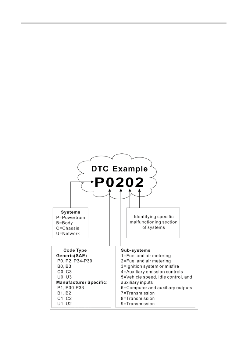
Trouble Codes consist of a five-digit alphanumeric code. The first character,
a letter, identifies which control system sets the code. The second character,
a number, 0-3; other three characters, a hex character, 0-9 or A-F provide
additional information on where the DTC originated and the operating conditions
that caused it to set. Here below is an example to illustrate the structure of the
digits:
P0201 - Injector circuit malfunction, Cylinder 1
5
LAUNCH
1.5 Location of the Data Link Connector (DLC)
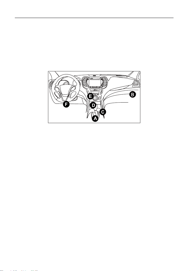
The DLC (Data Link Connector or Diagnostic Link Connector) is typically a 16-
pin connector where diagnostic code readers interface with the vehicle’s on-
board computer. It is usually located 12 inches from the center of the instrument
panel, under or around the driver’s side for most vehicles. For some vehicles
with special designs, the DLC location may vary.
Refer to the following gure for location.
A- Opel, Volkswagen, Audi
B- Honda
C- Volkswagen
D- Opel, Volkswagen, Citroen
E- Changan
F- Hyundai, Daewoo, Kia, Honda, Toyota, Nissan, Mitsubishi, Renault, Opel,
BMW, Mercedes-Benz, Mazda, Volkswagen, Audi, GM, Chrysler, Peugeot,
Regal, Beijing Jeep, Citroen and other most popular models
If the DLC cannot be found, refer to the vehicle’s service manual for the location.
6
LAUNCH
2. Product Descriptions
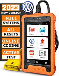
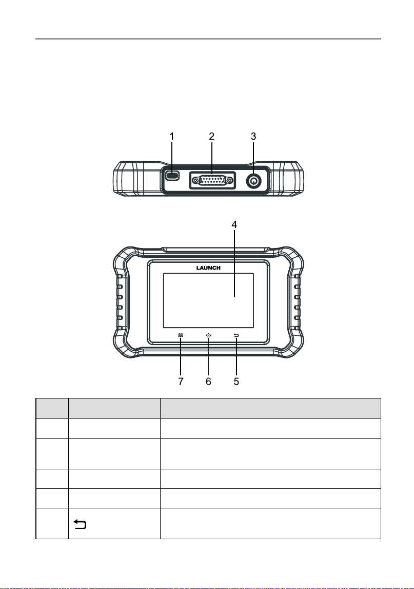
2.1 Components & Controls
No. Name Descriptions
1 Charging port Charge the tool via data cable (not included).
2
DB-15 diagnostic
connector
Connect the diagnostic cable.
3 Power button Turn on/o the tool.
4 Touch screen Indicate the test results.
5
BACK button
Exit the current program or return to the previous
screen.
7
LAUNCH
6 HOME button Navigate to the home (Job menu) screen.
7
Settings button Quick dial to the Settings module.
2.2 Technical Specications
• Screen: 4” touch screen with a resolution of 480*800
• CPU: 4-core 1.3GHz processor
• RAM: 2GB
• ROM: 16GB
• WiFi: 802.11b/g/n 2.4GHz
• OBD II input voltage range: 9~18V
• Power up via:
• DC 5V data cable (not included) or
• Diagnostic cable through connection to vehicle’s DLC
• Working temperature: -10 to 50°C (14 to 122 F°)
• Storage temperature: -20 to 70°C (-4 to 158 F°)
2.3 Accessories Checklist
For detailed accessory items, please consult from the seller.
1. Diagnostic scanner
2. Diagnostic cable
3. User manual
4. Quick start guide

8
LAUNCH
3. Initial Use
3.1 Powering Up The Tool
There are two methods available for powering up the tool:
Via Data Cable: Plug one end of data cable (not included) into the charging port
of the tool, and the other end to the PC.
Via Diagnostic Cable: Insert the diagnostic cable into the vehicle’s DLC port.
When the tool is powered on, the screen will automatically light up.
3.2 Getting Started
If it is the first time you have used this tool, you need to make some system
settings.
1. Press the [POWER] button to turn on the tool. The screen displays a welcome
page. Tap “Start” to go to next step.
2. Choose the desired system language, and tap “Next step”.
3. Choose the time zone of your current location. The system will automatically
congure the time according to the time zone you selected.
4. The system will automatically searching for all available Wi-Fi networks.
Choose the Wi-Fi needed.
5. After the network connection is done, tap “Next step” to congure workshop
information. Input the required information, and tap “Next step” to go to next
step.
*Note: After you congured it, the system will append it on the report every time a
report is successfully generated.
6. Carefully read all terms and conditions of the user agreement, check “Agree
to all the above terms”, and tap “OK” to complete the registration process. It
will automatically jump to the Job Menu.
3.3 Job Menu
It mainly includes the following function modules.
Diagnose Congure the tool to operate as a professional diagnostic tool.
9
LAUNCH
OBD II
This option presents a quick way to check for DTCs, isolate
the cause of the illuminated Malfunction Indicator Lamp (MIL),
check monitor status prior to emissions certification testing,
verify repairs, and perform a number of other services that are
emission-related.
Upgrade
To update vehicle diagnostic software and APK.
*Note: This function requires a stable network connection.
Mall
To subscribe extra vehicle diagnostic software or reset (special
function) software that are not included within the tool.
Settings
To manage data and make some system settings, including
Network setup, Workshop information and Brightness etc.
10
LAUNCH
4. Diagnose
4.1 Connection
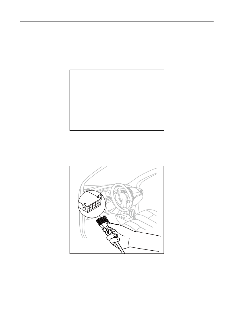
1). Turn the ignition o.
2). Locate the vehicle’s 16-pin Data Link Connector (DLC). Refer to Chapter 1.5.
3). Plug one end of the diagnostic cable into the vehicle’s DLC(Data Link
Connector) port, and the other end to the DB-15 diagnostic connector of the
tool, and then tighten the captive screws.
*Notes:
• A plastic DLC cover may be found for some vehicles and you need to remove it
before plugging the diagnostic cable.
• The cable connector is keyed and will only fit one way. If you have problems
connecting the cable connector to the DLC, rotate the connector 180
o
and try again.
4). Turn the ignition on. Engine can be o or running.

11
LAUNCH
Caution: Don’t connect or disconnect any test equipment with ignition on or engine
running.
4.2 System Diagnosing
This function is specially designed to diagnose electronic control systems of
single vehicle model.
*Notes:
1. The diagnostic software of the vehicle includes all kinds of reset software, user can
perform it (select Special function from the diagnostic function list) directly in this
module.
2. All software is updated periodically. It is recommended to update and install the latest
software version for the best service, functions and experience.
• Use and update of the diagnostic software pre-installed on the tool is free of
charge forever.
• Use and update of the diagnostic software purchased on the “Mall”
is free of
charge for one year. If it expires, user needs to renew the subscription.
3. More vehicle coverage can be extended on each model. Just go to “Mall” to subscribe
it.
4.2.1 Smart Diagnosis (Auto-Detect)
This function allows you to quickly access the electronic control systems of the
vehicle via decoding the VIN, without manual step-by-step menu selection.
After connection, turn the ignition key on and the system enters auto-detect
mode
.
*Notes:
• Make sure the “Automatic detection on connect” in “Settings” is set as ON.
• A highly stable and solid network connection is recommended for successful VIN
access.
A. Once the system successfully obtains the VIN (Vehicle Identication Number)
information of the currently identified vehicle, it will continue scanning the
vehicle systems. After the scanning is complete, a diagnostic report will be
automatically generated in the Settings -> Data -> Diagnostic Report.
B. If the tool failed to access the VIN information, the following screen will
appear:

12
LAUNCH
Input the VIN, and tap “OK”, the system will decode the VIN data
automatically, and continue the Smart Diagnosis procedure if success.
Otherwise the system will enter the Manual Diagnosis mode.
*Notes:
• The most recognizable location for this number is in the top left corner on the
vehicle’s dashboard. Other locations include the driver’s door or post, and the
rewall under the hood.
• In general, vehicle identification numbers are standardized - all contain 17
characters. VIN characters may be capital letters A through Z and numbers 1
through 0; however, the letters I, O and Q are never used in order to avoid mistakes
of misreading. No signs or spaces are allowed in the VIN.
4.2.2 Manual Diagnosis
If the tool cannot obtain or analyze the VIN information, you can also perform
Manual Diagnosis. In this mode, you need to execute the menu-driven command
and then follow the on-screen instruction to proceed.
*Notes:
• Before diagnosing, please make sure the corresponding vehicle manufacturer
software has been installed on the tool.
• The diagnostic menu may vary by the vehicle’s make, model and year.
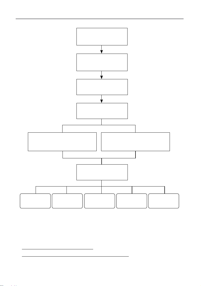
Refer to the owchart illustrated as below to diagnose a vehicle manually:
13
LAUNCH
Select “Diagnose”
Automatic System Detection
(System Scan)
Manual System Detection
(System Selection)
Select Scan Mode
Select Test Function
Select Vehicle Model
Select Vehicle
Manufacturer
Read Data
Stream
Special
Functions*
Read Fault
Code
Clear Fault
Code
Read Version
Information
Take DEMO V15.34 as an example to demonstrate how to diagnose a vehicle.
*Note: Illustrations used in this manual are samples, the actual testing screen may vary
for each vehicle being tested. The following illustrations are based on the DEMO with
basic functions. Vehicle diagnostic software with full systems and full functions can be
purchased in the Mall.
1). Select diagnostic software version: Tap “DEMO” to go to Step 2.
2
).
Select vehicle model (varies with dierent versions): Select the desired
vehicle model.

14
LAUNCH
3). Turn the ignition key to ON: Set the ignition switch to on.
4). Read vehicle information: After reading the vehicle information, double check
if the vehicle information is correct or not. If yes, tap “Yes” to continue.
5). Select test item: Select the desired test item to proceed.
4.2.2.1 Health Report (Quick Test)
This function varies from vehicle to vehicle. It enables you to quickly access all
the electronic control units of the vehicle and generate a detailed report about
vehicle health.
Tap “Health Report” on the test item selection screen, the system starts scanning
the ECUs. Once the scanning is complete, the following screen will appear:

15
LAUNCH
In above gure, the tested system with fault code is tagged with a red cross and
the system with OK displays with a green tick.
On-Screen Buttons:
Report: Tap to save the diagnostic result as a report.
Clear Code: Tap to clear the existing diagnostic trouble codes.
4.2.2.2 System Scan
This option allows you to quickly scan which systems are installed on the vehicle.
4.2.2.3 System Selection
This option allows you manually select the test system and function step by step.
Tap “System Selection” on the test item selection screen, and tap the desired
system (take “Engine” for example) to enter the test function selection screen.
*Note: Dierent vehicle has dierent diagnostic menus.
A. Read Fault Code
This function displays the detailed information of DTC records retrieved from the
vehicle’s control system.
Tap “Read Fault Code” on the test function selection screen, the screen will

16
LAUNCH
display the diagnostic result.
*Note: Retrieving and using DTCs for troubleshooting vehicle operation is only one part
of an overall diagnostic strategy. Never replace a part based only on the DTC denition.
Each DTC has a set of testing procedures, instructions and flow charts that must be
followed to conrm the location of the problem. This information can be found in the
vehicle’s service manual.
On-Screen Buttons:
Help: Tap to view the help information.
Code Search: Tap it to search for more information about the current DTC online.
Report: To save the current data in text format. All diagnostic reports can be
accessed from Settings -> Data -> Diagnostic Report.
B. Clear Fault Code
After reading the retrieved codes from the vehicle and certain repairs have been
carried out, you can use this function to erase the codes from the vehicle. Before
performing this function, please be sure the vehicle’s ignition key is in the ON
position with the engine o.
*
Notes:
1. If you plan to take the vehicle to a Service Center for repair, DO NOT erase the codes
from the vehicle’s computer. If data is erased, valuable information that might help the
technician troubleshoot the problem will also be erased.
2. Clearing DTCs does not x the problem(s) that caused the code(s) to be set. If proper
repairs to correct the problem that caused the code(s) to be set are not made, the
code(s) will appear again and the check engine light will illuminate as soon as the
problem that cause the DTC to set manifests itself.
C. Read Data Stream
This option retrieves and displays live data and parameters from the vehicle’s
ECU.
Tap “Read Data Stream” on the test function selection screen, the system will
display data stream items.

17
LAUNCH
On-Screen Buttons:
Select All: Tap it to select all items of the current page. To select certain data
stream item, just check the box before the item name.
Unselect: Tap it to deselect all data stream items.
OK: Tap it to conrm and jump to the next step.
After selecting the desired items, tap “OK” to enter the data stream reading
page.
*Notes:
1. If the value of the data stream item is out of the range of the standard (reference)
value, the whole line will display in red. If it complies with the reference value, it
displays in blue (normal mode).
2. The indicator 1/X shown on the bottom of the screen stands for the current page /
total page number. Swipe the screen from the right / left to advance /return to the next
/ previous page.
There are 3 types of display modes available for data viewing, allowing you to
view various types of parameters in the most suitable way.
• Value – Displays the parameters with numbers and lists.
• Graph – Displays the parameters with wave patterns.
• Combine – The graphs can be merged for easier comparisons. In this case,

18
LAUNCH
dierent items are marked in dierent colors.
On-Screen Buttons:
: Tap it to view the waveform graph of the current data stream item.
Combine: Tap it, a pull-down list of the data stream items appears on the screen.
Select the necessary items (Max. 4 items can be selected at the same time) and
the screen will display the waveforms corresponding to these items immediately.
Report: Tap to save the current data as a diagnostic report. All diagnostic reports
can be accessed from Settings -> Data -> Diagnostic Report. The tool logs the
Date of Report (the date and time at which the report was created) and assigns
a unique Report #.
Record: Tap to record and save Live Data. Recorded Live Data can serve as
valuable information to help you in troubleshooting and diagnosing vehicle
problems. All diagnostic records can be access from Settings -> Data ->
Diagnostic Record.
D. Special Functions
It oers coding, reset, relearn and more service functions, to help vehicles get
back to functional status after repair or replacement. Available tests vary by
vehicle manufacturer, model, and year.

19
LAUNCH
4.3 OBD II Diagnosis
This function presents a quick way to check for DTCs, isolate the cause of the
illuminated Malfunction Indicator Lamp (MIL), check monitor status prior to
emissions certification testing, verify repairs, and perform a number of other
services that are emission-related.
After the tool is properly connected to the vehicle’s DLC, tap “OBD II” in the
Job Menu. The tool will automatically start a check of the vehicle’s computer
to determine which type of communication protocol it is using, then display the
Monitor Status.
Tap “OK”, the following function list appears.
1. Read Codes
This function can identify which section of the emission control system has
malfunctioned.
2. Erase Codes
This function erases the codes from the vehicle, after retrieving codes from the
vehicle and certain repairs have been carried out.
Make sure the vehicle’s ignition key is in the ON position with the engine off
before the operation.
3. I/M Readiness
This function checks whether or not the various emissions-related systems on
the vehicle are operating properly, and are ready for Inspection and Maintenance
testing.
It can also be used to check the Monitor Run Status, and to conrm if the repair
of a car fault has been performed correctly.
4. Data Stream
This function retrieves and displays live data and parameters from the vehicle’s
ECU.
5. View Freeze Frame
This function takes the snapshot of the operating conditions when an emission-
related fault occurs.
*Note: If DTCs were erased, Freeze Data may not be stored in vehicle memory
depending on vehicle.
6. O2 sensor test
This function retrieves O2 sensor monitor test results of the most recently
completed tests from the vehicle’s on-board computer.

20
LAUNCH
7. On-board monitor test
This function retrieves test results for emission-related powertrain components
and systems that are not continuously monitored. The test’s availability is
determined by the vehicle manufacturer.
8. EVAP System Test
This function lets you initiate a leak test for the vehicle’s EVAP system. Refer to
the vehicle’s service repair manual to determine the procedures necessary to
stop the test.
9. Vehicle Info
This function retrieves a list of information (provided by the vehicle manufacturer)
from the vehicle’s on-board computer.
This information may include:
• VIN (Vehicle identication Number).
• CID (Calibration ID).
• CVN (Calibration Verication Number).
4.4 History
Generally once a vehicle diagnosis is performed, the tool will record the every
details of diagnostic session.
The History function provides direct access to the previously tested vehicles and
users can resume from the last operation, without starting from scratch.
Tap “History” on the Diagnose main menu screen, all diagnostic records will be
listed on the screen in date sequence.

21
LAUNCH
5. Upgrade
This function allows you to update the diagnostic app and software. All software
is updated periodically. It is recommended to update and install the latest
software version for the best service, functions and experience.
1). Use and update of the diagnostic software pre-installed on the tool is free of
charge forever. No subscription renewals are required.
2). Use and update of the diagnostic software purchased in the “Mall” is free
of charge for one year. If the free period is due, user needs to renew the
subscription. Refer to Chapter 5.2 for details.
*Note: Make sure the Wi-Fi connection is strong and stable while updating.
5.1 Update Diagnostic Software & App
Tap “Upgrade” on the Job menu to enter the update center.
By default, all diagnostic software is selected.
To deselect certain software, tap “Unselect”, and then check the box next to
vehicle model.
Tap “Update” to start downloading. It may take several minutes to nish, please
be patient.
Once download is nished, the software packages will be installed automatically.
5.2 Renew Subscription
When the free period is due, the diagnostic software of the current version will
be locked. To unlock it, user needs to renew the subscription.
Tap “Upgrade” on the Job menu to enter the update center.
All software that expires is displayed in gray. Select the desired diagnostic
software, tap “Renew”. Input the 24-digit pin code of Subscription Renewal Card
(*need to buy it from the seller or local dealer where you purchased the tool)
and then

22
LAUNCH
tap “Submit” to nish the renewal. Now the latest diagnostic software is ready for
use.
*Note: Please note that a piece of Subscription Renewal Card is only applicable to single
software, not to all software installed on this tool.

23
LAUNCH
6. Mall
This function allows you to subscribe other vehicle diagnostic software and reset
software that are not pre-installed on the tool.
All diagnostic software in the mall covers full systems and full functions
(excluding online programming and coding etc). Dierent vehicle software is
tagged with dierent price.
Tap “Mall” to open the online software mall. Select the target software and follow
the on-screen instructions to nish the transaction.
*Note: The software service belongs to the virtual goods. It becomes immediately
eective from the date of the successful transaction and it does not accept the refund.
When making payment, please double check the order information.
The subscribed software can be free to use and update for one year. After it
expires, it will become disabled. In this case, re-subscribe it in the Mall to unlock
it.

24
LAUNCH
7. Settings
7.1 Units of measurement
This option can set the measurement unit. Metric System and English System
are available.
7.2 Automatic detection on connect
This option enables you to determine whether to start an automatic VIN detection
once the tool is properly connected to the vehicle’s DLC.
7.3 Brightness
This item allows you to set the standby time and screen brightness.
*Note: Reducing the brightness of the screen is helpful to conserve the power of the tool.
7.4 Sound
This option lets you adjust the volume and other sound settings.
7.5 Network
The built-in WLAN module allows you to register the tool, update diagnostic
software & APK, and send email on a wireless network.
7.6 Time Zone
This option allows you to set the time zone.
7.7 Language
The tool supports multiple languages. You can use this option to change the
target language.
7.8 Workshop information
This option allows you to add a personalized tag on the diagnostic reports.
*Note: After you congured it, the system will append it on the report every time a report
is successfully generated.
7.9 Recovery
Use this item to reset this tool to the default factory setting.

25
LAUNCH
Warning: Resetting may cause data loss. Before doing so, please be careful to perform
this operation.
7.10 Clean Up
This option allows user to clear some cache les and free up the storage space.
7.11 Screen Capture
This option can set the Screen Capture icon to be shown or not on the screen.
7.12 About
This option displays the hardware configuration information of the tool and
license agreement.
7.13 Data
7.13.1 Diagnostic Record
This module stores the running parameters or waveform graphs the user
records.
7.13.2 Diagnostic Report
This module stores all diagnostic reports generated in the process of vehicle
diagnosis.
7.13.3 DTC Library
This function helps you to get the details of the DTC, which will greatly help
simplify the diagnostic process.
7.13.4 DLC (Data Link Connector) Location
This function helps you to nd the location of the vehicle’s DLC.

26
LAUNCH
7.13.5 Feedback
This function allows you to send the feedback of your diagnostic problems to us
for further analysis and troubleshooting.
7.13.6 Image
This option allows you to view and manage all screenshots. All screenshots
created in the vehicle diagnostic work will be saved in this module.
7.13.7 Firmware Fix
Use this module to upgrade and x diagnostic rmware. During xing, please do
not cut power or switch to other interfaces.
7.13.8 User Manual
The user manual is integrated on the tool for your easier check and reference.

27
LAUNCH
8. FAQ
Here we list some frequently asked questions and answers related to this tool.
1. System halts when reading data stream. What is the reason?
It may be caused by a slackened connector. Please turn this tool off, firmly
connect the connector, and switch it on again.
2. Screen of the tool ashes at engine ignition start.
Caused by electromagnetic disturbing, and this is normal phenomenon.
3. There is no response when communicating with on-board computer.
Please confirm the proper voltage of power supply and check if the throttle
has been closed, the transmission is in the neutral position, and the water is in
proper temperature.
4. What to do if the system fails to start auto VIN detection?
Please check the following possible reasons:
• Whether the tool is properly connected to the vehicle’s DLC port.
• Whether the “Automatic detection on Connect” switch is OFF. If yes, slide it to
ON.
5. Why are there so many fault codes?
Usually, it’s caused by poor connection or fault circuit grounding.
6. How to upgrade the system?
1. Switch the tool on and ensure a stable internet connection.
2. Tap “Settings” on the Job Menu, select “About” -> “Version”, and tap “Detect
the System Version” to enter the system upgrading page.
3. Follow the on-screen instructions step by step to finish the process. It may
take several minutes depending on the internet speed, please be patient. After
upgrade is successfully nished, the tool will automatically restart and enters
the Job menu.

28
LAUNCH
Warranty
This warranty is expressly limited to persons who purchase LAUNCH
®
products
for purposes of resale or use in the ordinary course of the buyer’s business.
LAUNCH
®
electronic product is warranted against defects in materials and
workmanship for one year (12 months) from date of delivery to the user.
This warranty does not cover any part that has been abused, altered, used for a
purpose other than for which it was intended, or used in a manner inconsistent
with instructions regarding use. The exclusive remedy for any automotive meter
found to be defective is repair or replacement, and LAUNCH shall not be liable
for any consequential or incidental damages.
Final determination of defects shall be made by LAUNCH in accordance with
stipulated procedures.
Order Information
Replaceable and optional parts can be ordered directly from your authorized tool
supplier. Your order should include the following information:
• Quantity
• Part number
• Item description
Customer Service
If you have any questions on the operation of the unit, please contact the seller,
or contact LAUNCH TECH CO., LTD.:
Website: www.x431.com
www.cnlaunch.com
Phone: +86 755 2593 8674
Email: [email protected]