Please read the user manual carefully before using this product.
Hunan Puqi Geologic Exploration Equipment Institute
Hunan Puqi Water Environment Institute Co.Ltd.
Hunan Puqi New Energy Institute Co.Ltd
Website:www.pqwtcs.comEmail:info@pqwtcs.com
Address:No. -Puqi building, No. Qingzhuhu Road,Qingzhuhu Street, Kaifu
District, Changsha, Hunan,China.
The Company reserves the right to upgrade and improve its products at any time without prior notice.The actual product specifications
shall prevail. The final right of interpretation is vested in the Company.
PQ SERIES
WATER LEAKS DETECTOR
U S E R M A N U A L
First Edition,

PRODUCT INTRODUCTION
MAIN PARAMETERS
MODEL
PQA
.m
MEASUREMENT
DEPTH
General Detection ,Location
Default levels, levels adjustable
Default levels, levels adjustable
Transmit data
PQB PQC PQD PQE
DETECTION
FUNCTION
m m m m
Indoor
Outdoor
Indoor/outdoor
The PQ series water leak detector is a new generation of intelligent detection
equipment independently developed by our institute, specifically designed for
pressure pipeline leak detection scenarios in municipal, firefighting, and thermal
energy applications. Equipped with a multi-sensor configuration, including the dual-
membrane resonance sensors DMR-V and DMR-H, the acoustic resonance sensors
RCS-L and RCS-S, and the trace leak detection sensor TLS-H, it offers flexible
adaptation to various detection needs such as external main pipelines and indoor
branch lines.
Leveraging its core technology of precise acoustic signal acquisition and intelligent
analysis algorithms, the instrument enables centimeter-level accuracy in locating leak
points. It effectively addresses industry challenges in detecting leaks in both outdoor
and indoor pressure pipelines, providing an efficient and intelligent technical solution
for municipal maintenance, fire safety, and household pipeline management.
DETECTION
MODE
GAIN
CONNECT TO
COMPUTER
VOLUME
Indoor:Hz-kHz Outdoor: Hz-kHz
FREQUENCY
ACQUISITION/
ADJUSTMENT
RANGE
Indoor/outdoor
Indoor/outdoor
/Gas
PRODUCT FEATURES
[HIGH-FREQUENCY PRECISION LEAK POINT DETECTION]
Utilizing a highly sensitive piezoelectric design, it quickly identifies high-frequency
leak signals generated by pipe cracks. With fast response, high positioning accuracy,
and strong anti-interference capabilities, it is suitable for use in urban water supply
mains, high-pressure water supply pipelines, and other applications, accurately
capturing subtle leaks.
[LOW-FREQUENCY DEEP PENETRATION DETECTION]
Through an optimized low-frequency resonance design, it easily penetrates thick-
walled pipes and deep buried layers, maintaining a high signal-to-noise ratio even in
noisy environments. It is suitable for deep detection in applications such as external
network pipelines, industrial water pipes, and deep underground water supply
systems.
[SMART HOME LEAK PREVENTION]
Equipped with lightweight acoustic acquisition technology, it can detect micro-
leaks in household pipes in real time. Compact, stable, and easy to install, it is an
ideal choice for home leak prevention, suitable for detecting tap water pipes, floor
heating pipes, and internal water use.
[TIME DOMAIN WAVEFORM VISUALIZATION ANALYSIS]
This feature provides active analysis that dynamically displays the strength of key
leakage signals. It supports active gain compensation to enhance leakage signals,
extracts leakage signal characteristics, tracks signal changes, and locks onto them,
enabling visual and interactive exploration of leakage conditions.
[INTELLIGENT LEAKAGE SIGNAL PROCESSING]
This feature leverages intelligent algorithms for software-level control, seamlessly
integrating with sensors. It can filter leakage signals at specific frequencies and
effectively suppress interference. It also supports adaptive filtering for on-demand
filtering, adapting to specific frequency bands with real-time adaptation to
environmental changes.
[DUAL MEMBRANE RESONANCE SENSOR ]
The double-layer piezoelectric ceramic membrane undergoes mechanical vibration
when receiving sound waves. When the frequency matches the natural frequency of
the ceramic membrane, resonance occurs, resulting in vibrational amplitude and
synergistic resonance. When the target measurement acts on the dual membrane,
the sensor detects changes in the resonance amplitude to capture the intensity of
the target quantity.
[ACOUSTIC CHAMBER RESONANCE SENSOR]
This type of sensor operates based on the reverberation and resonance
characteristics of sound waves within an acoustic chamber. By monitoring changes
in the reflection and superposition (reverberation) patterns of sound waves inside
the chamber, it captures sound wave signals conducted through the ground. Such
sensors leverage the "constraint and amplification" effect of the acoustic chamber
on sound waves, offering high sensitivity to minor vibrations.
[TRACER LEAK DETECTION SENSOR]
This sensor is used to detect leakage points in closed systems such as pipelines,
containers, and equipment. Its core principle involves tracking the diffusion
trajectory of a pre-introduced "tracer substance," such as a specific gas, to
accurately locate leakage points and assess the extent of leakage. Combining the
targeting capability of tracer technolog y with the sensitivity of detection
technology, this type of sensor is indispensable in applications such as pipeline leak
detection, industrial sealing tests, and equipment maintenance.
dB
SIGNAL-TO-
NOISE RATIO
-dB
THD+N
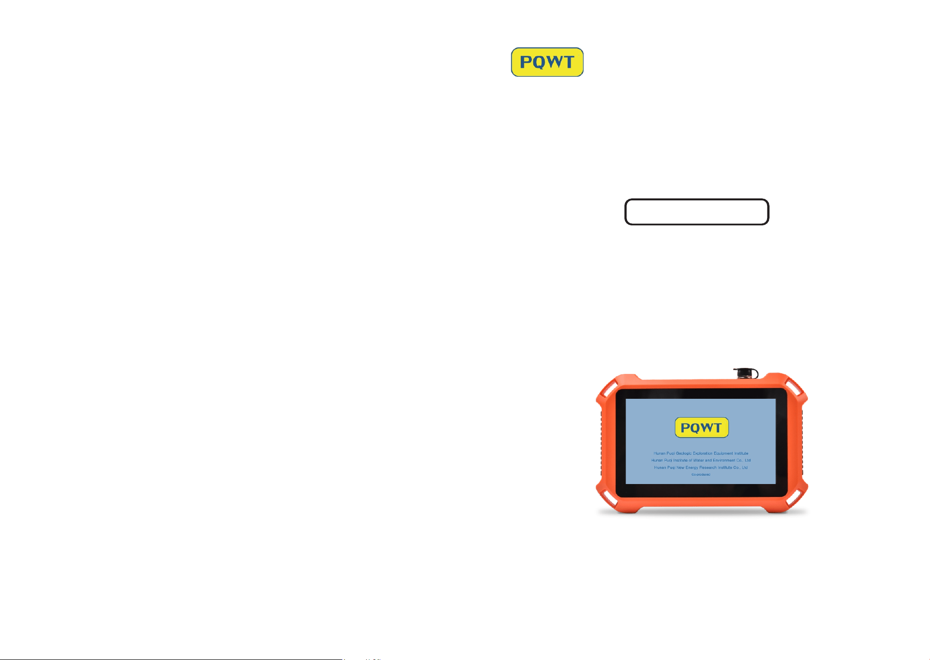
PQ125APARTSLIST
PQBPARTSLIST
DMR-H
DMR-V
Control
Handle
RCS-S
Listening rod
PQC PARTSLIST
PQD PARTSLIST
Control
Handle
DMR-H
DMR-V
Control
Handle
RCS-S
Listening rod
DMR-H
DMR-V
Control
Handle
RCS-S
RCS-L
Listening rod
PRODUCT COMPOSITION
.ACCESSORIES DESCRIPTION
Host Machime
Identify the type of inserted sensor
Can record audio
Default %, infinitely adjustable
Default not sleep, Can be set to minutes, minutes, minutes
automatic sleep
SENSOR
DETECTION
RECORD
BRIGHTNESS
ADJUSTMENT
SLEEP
-inch LCD screen resolution *
-℃~℃
≈W
≤ Hours
- Hours
DISPLAY
SCREEN
WORKING
TEMPERATURE
POWER
CONSUMPTION
WORKING
TIME
CHARGING
TIME
VA USB charging
.V mAh
Host .kg
Host size: xxmm
CHARGER
BATTERY
PRODUCT
WEIGHT
PRODUCT
SIZE
kHz
-bit
GB
SAMPLING RATE
ADC
MICRO SD
Intelligent Time Domain Waveform
Ground-Receiving
±dB SPL (kHz)
PNEAUD H -bit Processor
dB~dB SPL
AI
DIRECTIONAL
PATTERN
SENSITIVITY
CORE
PROCESSOR
SENSOR RANGE
Closed-Back Noise Cancelling (Stereo)Ω±%
φ50mm
Indoor:±.m Outdoor:±m
MONITOR
HEADPHONES
TRANSDUCER
SPECIFICATIONS
POSITIONING
RANGE
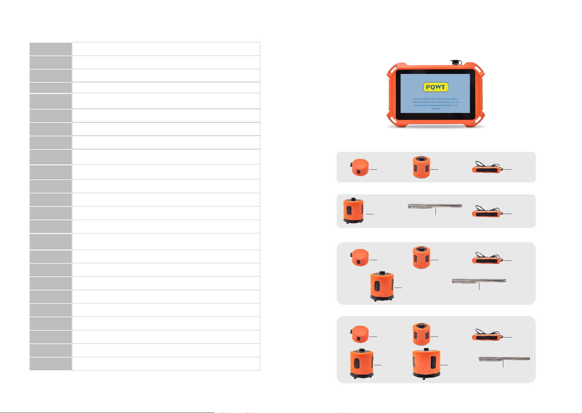
①Switch Button: press to turn on/off;
②Reset Button: force shutdown;
③SD Card Slot: SD storage card;
④Type-C Interface: charging and connecting data;
⑤System Operation Indicator: display the operating status of the system;
⑥Headphone Interface: connect headphones;
⑦Air Plug Interface: connect the control handle.
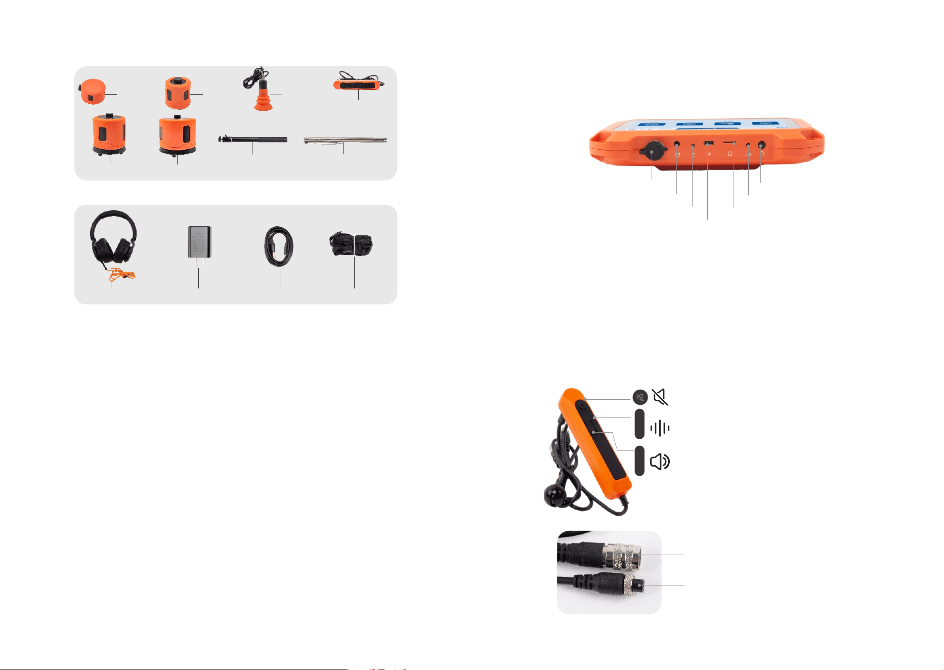
CONTROL HANDLE
+
+
-
-
+
+
-
-
SOUND BUTTON: press the button to collect sound,
press again to stop collecting;
ADJUST GAIN: press + or - to adjust gain;
ADJUST VOLUME: press + or - to adjust volume.
M AVIATION PLUG: connect to sensor;
GX AVIATION PLUG: connect to host.
OTHERS
Charger
Headphones
HOST: collect and process data.
CONTROL HANDLE: connect acoustic sensor and host.
DMR-V: Used for routine indoor ground detection, convenient for handheld
operation and mobility.
DMR-H: Used for detecting narrow indoor spaces, such as gaps between objects and
walls, offering more contact area and higher accuracy.
RCS-S: Used for outdoor hard and soft ground, detecting pipeline networks with metal
or plastic pipe diameters ≤ mm and burial depths up to meters.
RCS-L: Used for outdoor hard and soft ground, detecting pipeline networks with metal
or plastic pipe diameters ≥ mm and burial depths up to meters.
Listening Rod: Used to connect RCS-S or RCS-L sensors when detecting soft muddy
ground.
TLS-H: It is used for tracer gas detection. A hydrogen-nitrogen mixture (% nitrogen,
% hydrogen) is injected into the pipeline, which can also be produced on-site using a
hydrogen generator to ensure flexible and convenient gas supply. The gas diffuses
inside the pipeline. If there is a leakage point, the gas will escape from it. The sensor
detects the concentration of the escaping gas signal to locate the leakage area and
position, with a detection depth of up to meters.
STRAP: connect to the host strap slot.
USB DATA CABLE: connect to the computer and transmit host data.
CHARGER: used to charge the device.
.EQUIPMENT INTERFACE DESCRIPTION
①Switch Button
④Type-C Interface
⑤System Operation Indicator
⑥Headphone Interface
③SD Card Slot
②Reset Button
⑦Air Plug Interface
USB Data Cable Strap
HOST MACHINE
PQE PARTSLIST
Telescopic Rod
DMR-H
DMR-V
Control
Handle
TLS-H
RCS-S
RCS-L
Listening rod
STEP :
Connect the host and
the shoulder strap;
STEP :
O p e n t h e b l a c k
cover of the host's
a vi at i on s o ck et ,
align the groove of
the GX aviation
p l u g w i t h t h e
convex position of
the host's aviation
socket, and tighten
t h e n u t o n t h e
aviation plug;
STEP :
Open the black
c o v e r o f t h e
sensor's aviation
socket, align the
groove of the M
aviation plug with
the convex position
of the sensor, and
tighten the nut on
the aviation plug;
STEP :
Align the earphone
plug with the host's
earphone jack and
insert it.
Press and hold the host's power button for - seconds to turn on the machine,
enter the power-on interface, and then enter the main interface. As shown below:
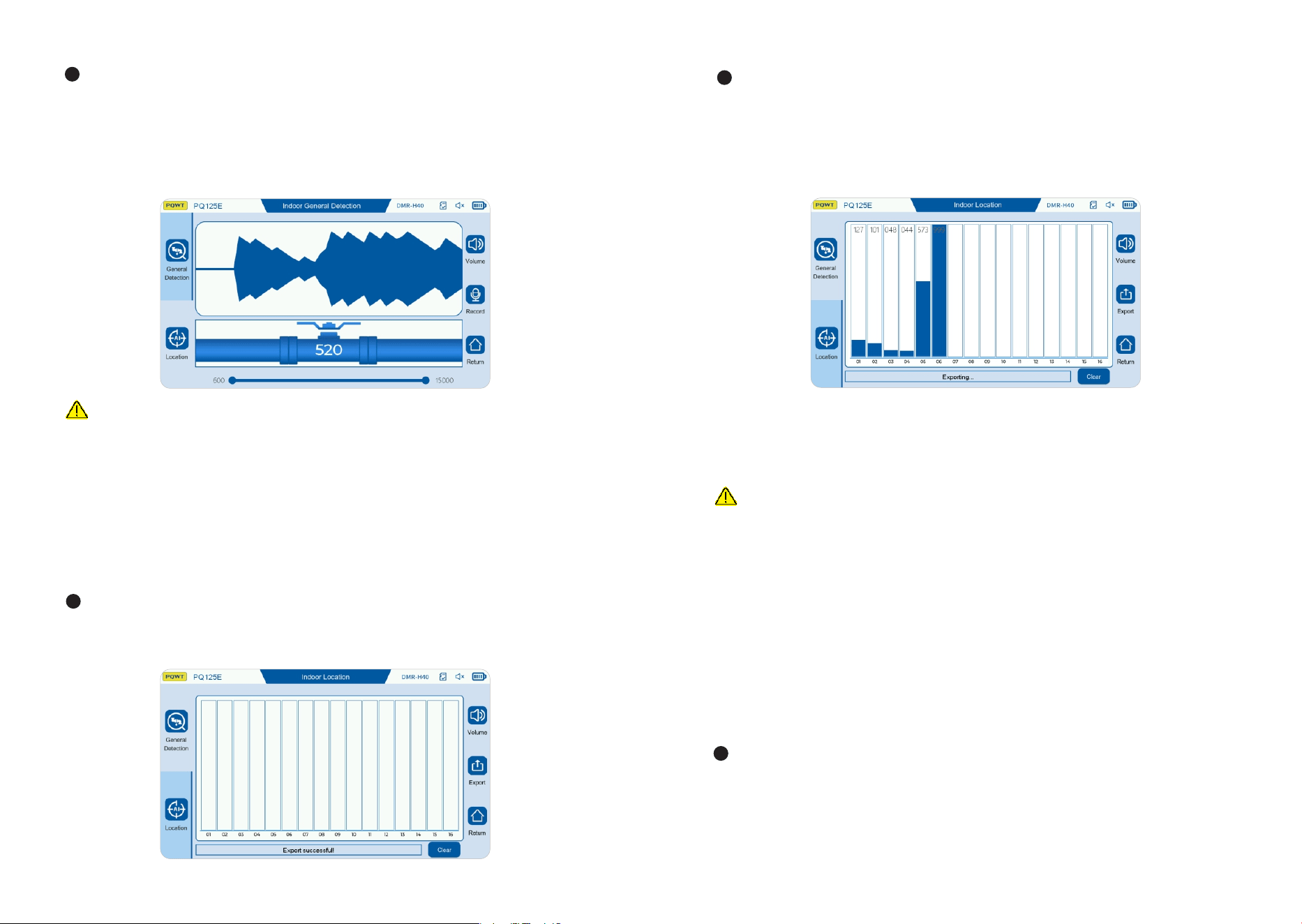
After entering the main interface, click the "Indoor" button to enter the indoor
General Detection mode. As shown below:
GENERAL DETECTION MODE
①
②
③
④
⑤
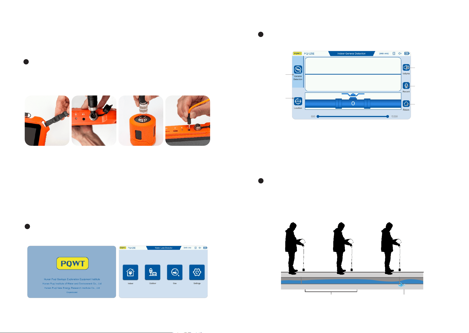
Select“ DMR-V" or“ DMR-H" sensor according to the indoor use environment,
connect the GX aviation plug of the control handle to the host, connect the M
aviation plug of the control handle to the sensor, insert the earphone into the
earphone jack of the host, and connect the host to the shoulder strap. As shown
below:
OPERATION INSTRUCTIONS
(Take PQE as an example)
.INDOOR DETECTION
① General Detection: Click to enter the General Detectionmode;
③ Volume: Volume adjustment;
② Location: Click to enter the Location mode;
④ Record: Click to record in real time:
⑤ Return: Click to return to the main interface.
Place the sensor on the ground above the pipe, adjust the volume to , and the gain
to . Press the control handle switch to monitor the water leakage, and press the
control handle switch again to stop the water leakage monitoring. The sensor moves
along the ground above the tested pipe for detection, each moving distance is .
meters, and the stay time at one point is about - seconds. As shown below:
.m
Stay at each point for - seconds
After the detection of point is completed, move the sensor to the next point
position, repeat the previous operation, and so on. The signal collection of points
can be completed for signal comparison.
TIPS
. This mode is generally suitable for areas where the leakage range has been roughly
determined or where the signal crosstalk occurs. While positioning and detecting,
you can also use headphones to listen to the sound wave signal of each point for
comparison;
. Click the "Clear" button to clear all positioning data:
. Click the "Export" button to capture the positioning interface picture and save it to
the SD storage card.
. OUTDOOR DETECTION
Choose a“ RCS-L" or“ RCS-S" sensor according to the use environment, connect
the GX aviation plug of the control handle to the host, connect the M aviation
plug of the control handle to the sensor, insert the earphone into the headphone jack
of the host, and connect the host strap. As shown below:
TIPS
. If this happens, it is initially judged that the leak is a suspected leak. The sound caused
by the vibration of the tee and elbow should be excluded. In addition, during the peak water
usage, the water flow is fast, and the sound of the faucet will also produce continuous sound.
This method is suitable for detection at night when the water usage is low;
. The recording function is mainly used to record the sound at the leak point on site. Click
the recording button to start recording, and click the stop button to stop recording. After the
recording is completed, the audio file is saved in the record data folder of the memory card.
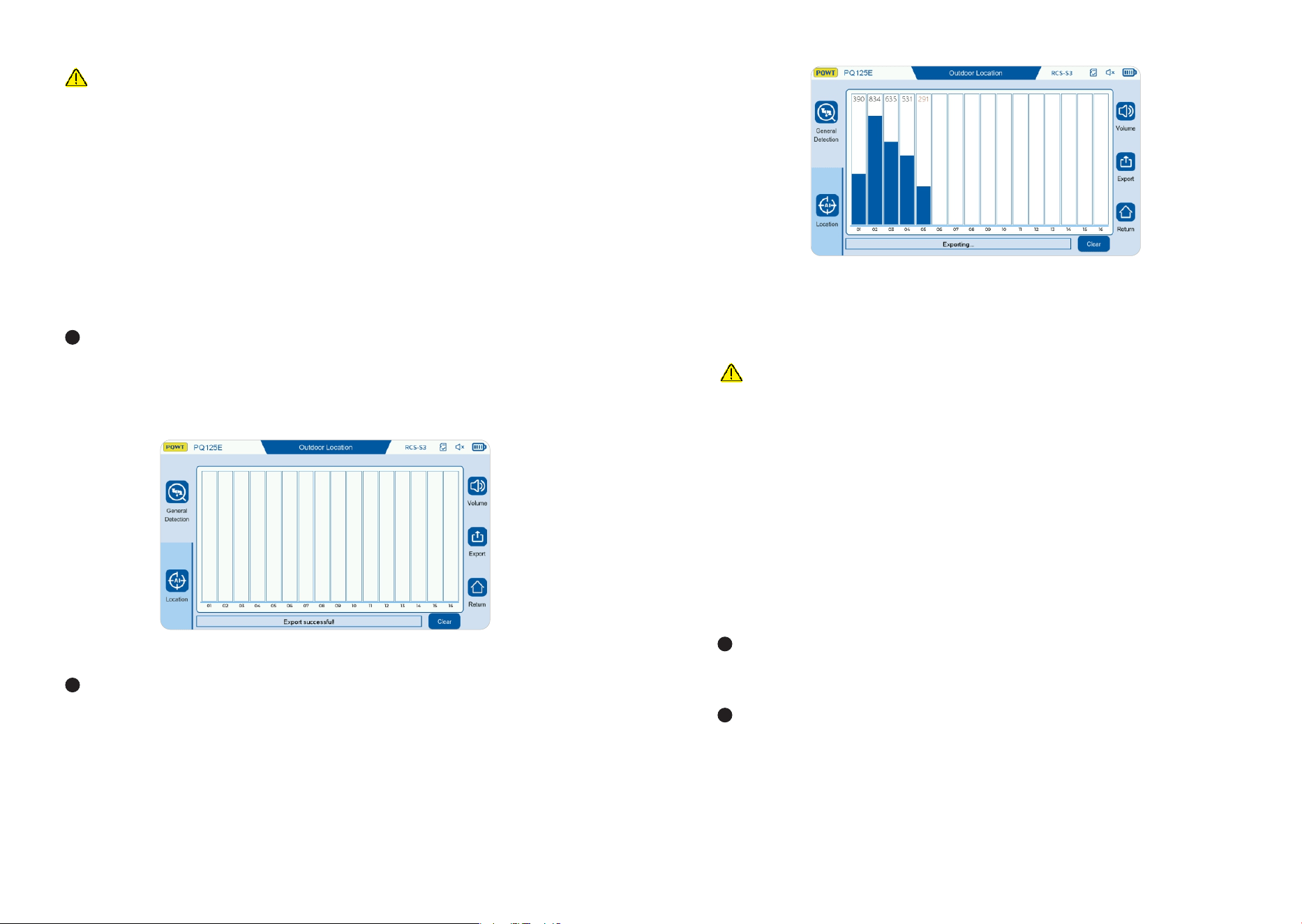
LOCATION MODE
Click the "Location" button to enter the "positioning" mode. The screen displays
the information collection box of points, that is, the signals of points are
collected and retained on the screen, which is convenient for comparing the signal
strength of each point, so as to determine the leak location. As shown below:
Place the acoustic sensor on the ground above the detection pipeline, and "click"
any position in the box from in sequence, and a blue column will appear. The
signal value will appear above the column. When the signal value is red, the
instrument starts to collect valid signals. After the thick column is completely stable,
click anywhere in the column frame, and the blue signal column will lock and stop.
At this time, the signal value color is displayed in black, which means it is locked.
As shown in the figure below:
During the detection process, when the sensor moves from one point to the next, the
operator should keep the sound signal memory of the previous point to facilitate signal
comparison between points. When the sound is found to be different from other places
or becomes larger, the time domain dynamic waveform is continuous and the amplitude
is stable, there may be a suspicion of water leakage here. With this point as the center,
compare the signal strength from front to back and left to right to determine the
suspected water leakage location. As shown below:

Press and hold the host's power button for - seconds to turn on the machine, enter
the power-on interface, and then enter the main interface. As shown below:
After entering the main interface, click the "Indoor" button to enter the indoor General
Detection mode. As shown below:
GENERAL DETECTION MODE
①
②
③
④
⑤
① General Detection: Click to enter the General Detection mode;
② Location: Click to enter the positioning mode;
③ Volume: Volume adjustment;
④ Record: Click to record in real time:
⑤ Return: Click to return to the main interface.
Place the sensor on the ground above the pipe, adjust the volume to , and the
gain to . Press the control handle switch to monitor the water leakage, and press
the control handle switch again to stop the water leakage monitoring. The sensor
moves along the ground above the tested pipe for detection, each moving
distance is meters, and the stay time at one point is about - seconds. As
shown below:
STEP :
Connect the host and
the shoulder strap;
STEP :
O p e n t h e b l a c k
cover of the host's
av iat io n s o cke t,
align the groove of
the GX aviation
p l u g w i t h t h e
convex position of
the host's aviation
socket, and tighten
t h e n u t o n t h e
aviation plug;
STEP :
Open the black
c o v e r o f t h e
sensor's aviation
socket, align the
groove of the M
aviation plug with
the convex position
of the sensor, and
tighten the nut on
the aviation plug;
STEP :
Align the earphone
plug with the host's
earphone jack and
insert it.
m
Stay at each point for - seconds
During the detection process, when the sensor moves from one point to the next,
the operator should keep the sound signal memory of the previous point to
facilitate signal comparison between points. When the sound is found to be
different from other places or becomes larger, the time domain dynamic
waveform is continuous and the amplitude is stable, there may be a suspicion of
water leakage here. With this point as the center, compare the signal strength
from front to back and left to right to determine the suspected water leakage
location. As shown below:
TIPS
.This mode is generally suitable for areas where the leakage range has been roughly
determined or where the signal crosstalk occurs. While positioning and detecting, you
can also use headphones to listen to the sound wave signal of each point for comparison;
. Click the "Clear" button to clear all positioning data;
. Click the "Export" button to capture the positioning interface picture and save it to the
SD storage card.
. GAS TRACER DETECTION
Inject hydrogen-nitrogen mixed gas (nitrogen %, hydrogen %) into the pipeline
to be tested.
Install the TLS-H sensor, align the aviation plug on the sensor connection line
with the main engine aviation socket, and connect the main engine to the strap. As
shown below:
LOCATION MODE
Click the "Location" button to enter the "positioning" mode. The screen displays the
information collection box of points, that is, the signals of points are collected
and retained on the screen, which is convenient for comparing the signal strength of
each point, so as to determine the leak location. As shown below:
Place the acoustic sensor on the ground above the detection pipeline, and "click"
any position in the box from in sequence, and a blue column will appear. The
signal value will appear above the column. When the signal value is red, the
instrument starts to collect valid signals. After the thick column is completely
stable, click anywhere in the column frame, and the blue signal column will lock
and stop. At this time, the signal value color is displayed in black, which means it is
locked. As shown in the figure below:
After the detection of point is completed, move the sensor to the next point
position, repeat the previous operation, and so on. The signal collection of
points can be completed for signal comparison.
TIPS
.If this happens, it is initially judged that the leak is a suspected leak. The sound caused
by the vibration of the tee and elbow should be excluded. In addition, during the peak
water usage, the water flow is fast, and the sound of the faucet will also produce continuous
sound. This method is suitable for detection at night when the water usage is low;
.The recording function is mainly used to record the sound at the leak point on site. Click
the recording button to start recording, and click the stop button to stop recording. After the
recording is completed, the audio file is saved in the record data folder of the memory card.
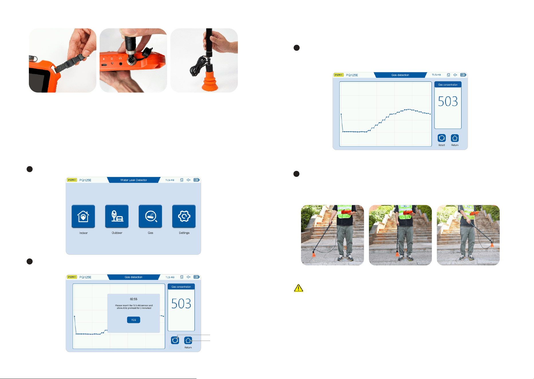
Put the sensor close to the ground for sector scanning detection. As shown in the
following figure, when the sensor detects gas leakage, the signal column and
value will change. The closer to the gas leakage location, the larger the signal
column and value will be, and vice versa.
TIPS
. Since gas can only penetrate into the ground from the penetrable medium, the position
with the maximum detection value is not necessarily the position of the pipeline leakage;
. The gas detection mode is only applicable to determining the approximate range of the
pipeline leakage position. If you need to improve the positioning accuracy of the pipeline
leakage, please combine the external network detection function for judgment.
Click "Gas" to enter the gas detection mode. As shown below:
Wait for the sensor to preheat for minutes according to the prompt. After preheating,
click Confirm. As shown below:
If there is a value on the signal column and the numerical display, you need to click
the reset button to clear the value to , and then perform gas detection. If there is
no value, you can directly detect it after preheating. As shown below:
①
②
①Reset:Clear the current value; ②Return:Return to the main interface.
Reset
STEP :
Connect the main engine
and the strap;
STEP :
Open the black cover of the
m a i n e n g i n e a v i a t i o n
socket, align the groove
p o s i t i o n o f t h e G X
av i at ion plu g wit h the
convex position of the main
engine aviation socket, and
tighten th e nu t o n t he
aviation plug;
STEP :
Align the metal head of the
telescopic rod with the TLS-
H sensor socket, insert it
and tighten it.
BATTERY MANAGEMENT
When placing the battery, the positive and negative poles of the battery plug must
correspond to the socket. Please use the original charger for charging;
The battery must not be close to open flames and high temperature sources, must
not be exposed to the sun, must not be burned, and must not be collided. The
charger and battery should be kept away from the bedroom and away from
flammable materials, and the charger should be placed in a place where heat can
be easily dissipated and kept dry;
The continuous charging time should not exceed hours. After full charging, the
charging power supply must be disconnected in time to prevent overcharging
from causing the diaphragm to break and short-circuit and explosion.
For long-term storage without use, it is recommended to perform a charging
maintenance every months to prevent battery damage caused by over-
discharge.
NOTES
When using the instrument, please pay attention to the correct operation method.
Correct usage habits will extend the life of the instrument;
The instrument is not waterproof, please pay attention to waterproofing;
Pay attention to protecting the LCD screen, do not expose the screen to direct
sunlight for a long time, if there is a freeze or touch failure, please shut down and
restart;
Please store the instrument in a cool and dry place;
It is forbidden to disassemble and repair the instrument without authorization,
otherwise it may cause instrument data errors or system crashes.
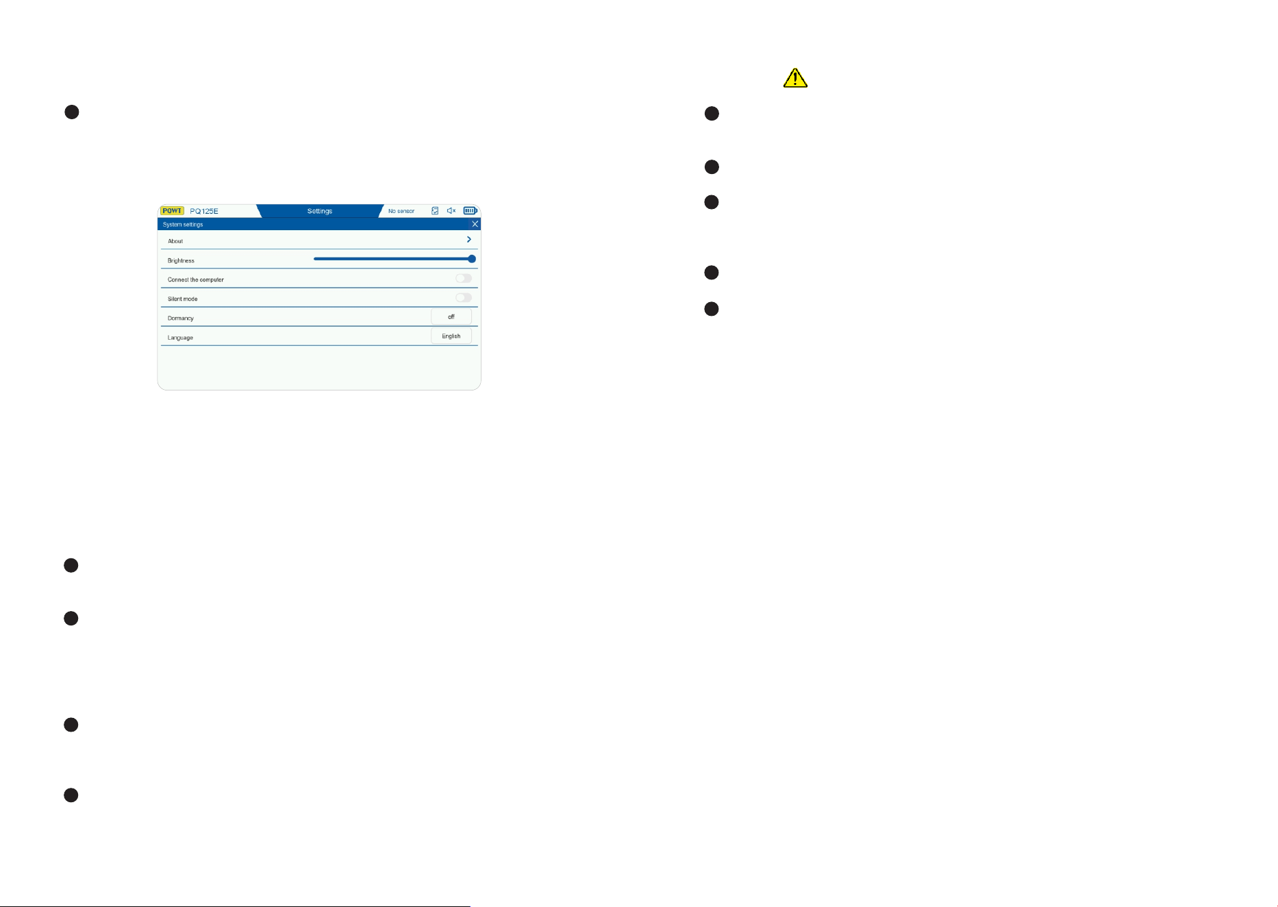
.SETTINGS
Click the "Settings" button to enter the settings interface, where you can adjust the
screen brightness. The default screen brightness is %. The interface has the
following functions: connect to the computer, silent mode, sleep, and language
selection. Click "About" to enter the about interface to view the host information.
As shown in the figure below:
In the illustration above, Silent Mode can be turned on or off according to user
preference. The function of the handle switch will change accordingly:
When Silent Mode is on, press and hold the handle switch to enable sound, and
release it to turn off the sound.When Silent Mode is off, a short press turns the
sound on, and pressing again turns the sound off.