ENGLISH
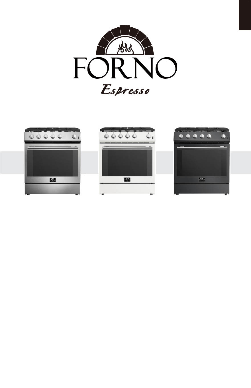
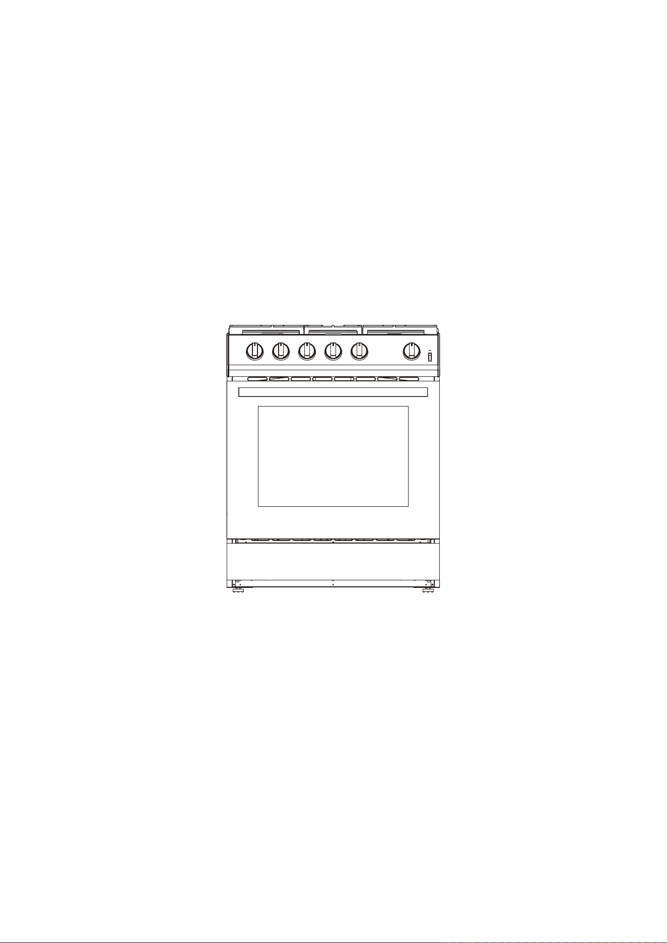
GAS RANGE
MODEL NUMBER SERIES
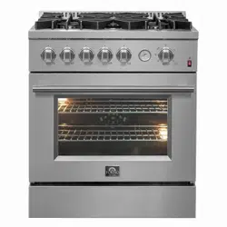
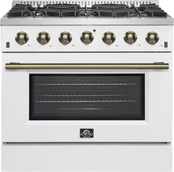
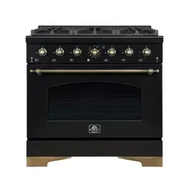
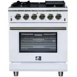
FFSGS1116-30 | FFSGS1116-30BLK | FFSGS1116-30WHT
INSTALLATION GUIDE
Read these instructions carefully before using your appliance, and keep it carefully.
If you follow the instructions, your appliance will provide you with many years of good service.
05/2026

Table of Contents
RANGE SAFETY ................................................................................................. 3
Anti-tip Device ........................................................................................................... 4
INSTALLATION REQUIREMENTS ...................................................................... 6
Tools and Parts .......................................................................................................... 6
Location Requirements ........................................................................................... 8
Installation Requirement......................................................................................... 10
Venting Requirements ............................................................................................. 12
Electrical Requirements ........................................................................................... 13
Gas Supply Requirements ...................................................................................... 16
INSTALLATION INSTRUCTIONS ...................................................................... 19
Unpack Range .......................................................................................................... 19
Install Anti-tip Device ............................................................................................. 20
Install Backsplash .................................................................................................... 22
Gas Connection ....................................................................................................... 23
Complete Connection ............................................................................................ 25
Adjust Flame Height ............................................................................................... 27
Level Range .............................................................................................................. 28
GAS CONVERSION ................................................................................................... 30
2
Range Safety
WARNING
Fire Hazard
If the information in this manual is not followed exactly, a re or explosion may
result causing property damage, personal injury or death.
- Do not store or use gasoline or other ammable vapors and liquids in the vicinity of
this or any other appliance.
- WHAT TO DO IF YOU SMELL GAS
• Do not try to light any appliance.
• Do not touch any electrical switch.
• Do not use any phone in your building.
• Clear the room, building, or area of all occupants.
• Immediately call your gas supplier from a neighbor’s phone. Follow the gas
supplier’s instructions.
• If you cannot reach your gas supplier, call the re department.
- Installation and service must be performed by a qualied installer, service agency
or the gas supplier.
WARNING
Never Operate the Top Surface Cooking Section of this Appliance Unattended.
• Failure to follow this warning statement could result in re, explosion, or burn haz-
ard that could cause property damage, personal injury, or death.
• If a re should occur, keep away from the appliance and immediately call your re
department.
DO NOT ATTEMPT TO EXTINGUISH AN OIL/GREASE FIRE WITH WATER
3
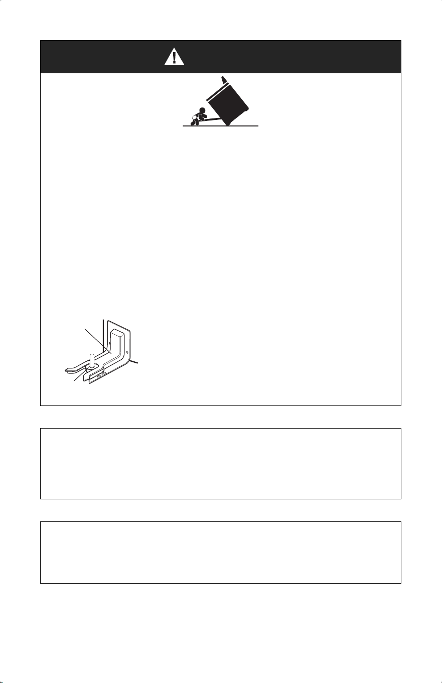
WARNING
Tip Over Hazard
• A child or adult can tip the range and be killed.
• Install anti-tip bracket to oor or wall per installation instructions.
• Slide range back so rear range foot is engaged in the slow of the anti-top bracket.
• Re-engage the anti-tip bracket if range is moved.
• Do not operate the range without anti-tip bracket installed and engaged.
• Failure to follow these instructions can result in death or serious burns to children
and adults.
Anti-Tip
Bracket
Range
Foot
Making sure the anti-tip bracket is installed:
• Slide range forward.
• Look for the anti-tip bracket securely attached to oor
and wall.
• Slide range back so rear range foot is under anti-tip
bracket.
WARNING: Gas leaks cannot always be detected by smell.
Gas suppliers recommend that you use a gas detector approved by UL or CSA.
For more information, contact your gas supplier.
WARNING: Do not install a ventilation system that blows air downward toward this
cooking appliance. This type of ventilation system may cause ignition and combus-
tion problems with this cooking appliance resulting in personal injury or unintended
operation.
4
You can be killed or seriously injured
if you don’t immediately follow
instructions.
You can be killed or seriously injured
if you don’t follow instructions.
A potentially hazardous situation
which, if not avoided, could result in
minor or moderate injury.
All safety messages will tell you what the potential hazard is, tell you how to reduce
the chance of injury, and tell you what can happen if the instructions are not fol-
lowed.
Your safety and the safety of others are very important. We have provided
many important safety messages in this manual and on your appliance. Always read
and obey all safety messages.
This is the safety alert symbol.
This symbol alerts you to potential hazards that can kill or hurt
you and others.
All safety messages will follow the safety alert symbol and
either the word “DANGER,” “WARNING” or “CAUTION.”
These words mean:
DANGER
WARNING
CAUTION
In the State of Massachusetts, the following installation instructions apply:
• Installations and repairs must be performed by a qualied or licensed contractor,
plumber, or gastter qualied or licensed by the State of Massachusetts.
• If using a ball valve, it shall be a T-handle type.
• A exible gas connector, when used, must not exceed 3 feet.
5
Installation Requirements
TOOLS AND PARTS
Gather the required tools and parts before starting installation. Read and follow the
instructions provided with any tools listed here.
Tools Needed
• Tape measure
• Flat-blade screwdriver
• Phillips screwdriver
• Level
• Drill
• Wrench or pliers
• Pipe wrench
• 15/16” (2.4 cm) combination
wrench
• 1/8” (3.2 mm) drill bit (for wood
oors)
• Marker or pencil
• Pipe-joint compound resistant to
Propane gas
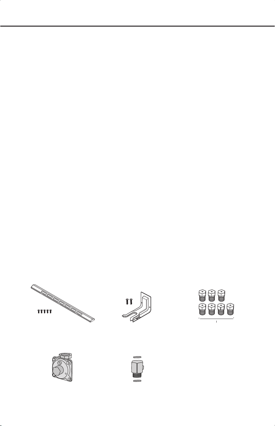
Parts Supplied
• 3/16” (4.8 mm) carbide-tipped
masonry drill bit (for concrete/ce-
ramic oors)
• Noncorrosive leak-detection
solution
Backsplash with screws Anti-tip bracket with screws
Gas pressure regulator Gas pipe adapter with washers
6
LP Gas Conversion kit

Gas supply line kit
(supply line and 2 adapters)
Parts Needed
7
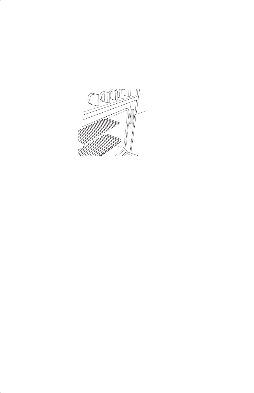
Rating Plate
LOCATION REQUIREMENTS
IMPORTANT: Observe all governing codes and ordinances. Do not obstruct ow of
combustion and ventilation air.
•It is the installer’s responsibility to comply with installation clearances specied on
the model/serial rating plate. The model/serial rating plate is located behind the oven
door on the oven frame.
• The range should be located for convenient use in the kitchen.
• Recessed installations must provide complete enclosure of the sides and rear of the
range.
• To eliminate the risk of burns or re by reaching over heated surface units, cabinet
storage space located above the surface units should be avoided. If cabinet storage is
to be provided, the risk can be reduced by installing a range hood or microwave hood
combination that projects horizontally a minimum of 5” (12.7 cm) beyond the bottom
of the cabinets.
• All openings in the wall or oor where range is to be installed must be sealed.
• Do not seal the range to the side cabinets.
• Cabinet opening dimensions that are shown must be used.
• Grounded electrical supply is required. See “Electrical Requirements” section.
• Proper gas supply connection must be available. See “Gas Supply Require-
ments” section.
• Contact a qualied oor covering installer to check that the oor covering can with-
stand at least 200°F (93°C).
• Use an insulated pad or 1/4” (0.64 cm) plywood under range if installing range over
carpeting.
8

Mobile Home - Additional Installation Requirements
• The installation of this range must conform to the Manufactured Home Construction
and Safety Standard, Title 24 CFR, Part 3280 (formerly the Federal Standard for
Mobile Home Construction and Safety, Title 24, HUD Part 280). When such stan-
dard is not applicable, use the Standard for Manufactured Home Installations, ANSI
A225.1/NFPA 501A or with local codes.
In Canada, the installation of this range must conform with the current standards
CAN/CSA-A240-latest edition, or with local codes.
Mobile Home Installations Require:
• When this range is installed in a mobile home, it must be secured to the oor during
transit. Any method of securing the range is adequate as long as it conforms to the
standards listed above.
• Four-wire power supply cord or cable must be used in a mobile home installation.
The appliance wiring will need to be revised. See “Electrical Connection” section.
9
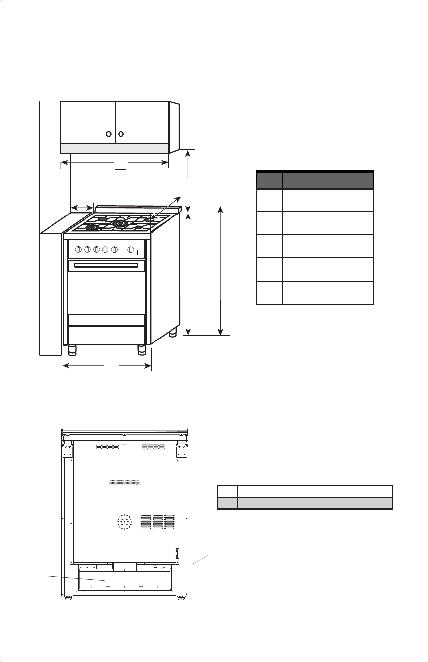
a
5.9” (15 cm)
Min.
b
30” (76 cm)
Min.
d e
b
a
INSTALLATION REQUIREMENTS
NOTE: Range can be raised approximately 1” (2.5 cm) by adjusting the leveling legs.
Front of door and drawer may extend farther forward depending on styling.
10
Dimension
a
30” (76 cm)
b
30” (76 cm)
c
25” (63.5 cm)
d
36” (91.4 cm)
e
37¾” (96 cm)
A
Power Cord
B
Recessed Area
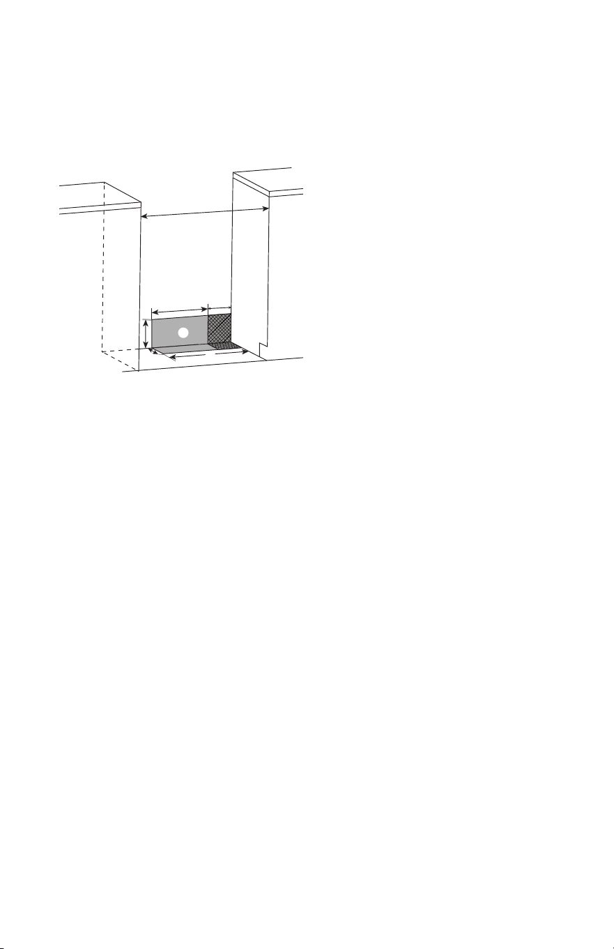
d
e
b
g
a
c
f
h
Power Supply Location
IMPORTANT: An electrical outlet in the oor, may be either recessed or surface mount-
ed, but an electrical outlet in the wall must be recessed to make the connection. For
Direct Wiring, the electrical box should be mounted to the wall.
11
a
b
c
d
e
f
g
h
30” (76 cm)
11½” (29.2 cm)
6” (15.2 cm)
7¼” (18.4 cm)
3” (7.6 cm)
17½” (44 cm)
Recommended Location for
Electrical Outlet
Recommended Location for
Gas Supply Connection

VENTING REQUIREMENTS
IMPORTANT: This range must be exhausted outdoors unless you are using ductless
venting. Observe all governing codes and ordinances. Do not obstruct ow of combustion
and ventilation air.
• Do not terminate the vent system in an attic or other enclosed area.
• Use an approved vent cap for proper performance. If an alternate wall or roof cap is
used, be certain the cap size is not reduced and that it has a backdraft damper.
• Vent system must terminate to the outside unless you are using a ductless vent kit.
• Rigid metal vent is recommended. For best performance, do not use plastic or metal foil
vent.
• If a joist or stud must be cut, then a supporting frame must be constructed.
• The size of the vent should be uniform.
• The vent system must have a damper.
• Seal all joints in the vent system.
• Use caulking to seal exterior wall or roof opening around the cap.
• Determine which venting method is best for your application.
Makeup Air
Local building codes may require the use of makeup air systems when using
ventilation systems greater than specied CFM of air movement. The specied CFM
varies from locale to locale. Consult your HVAC professional for specic requirements in
your area.
12
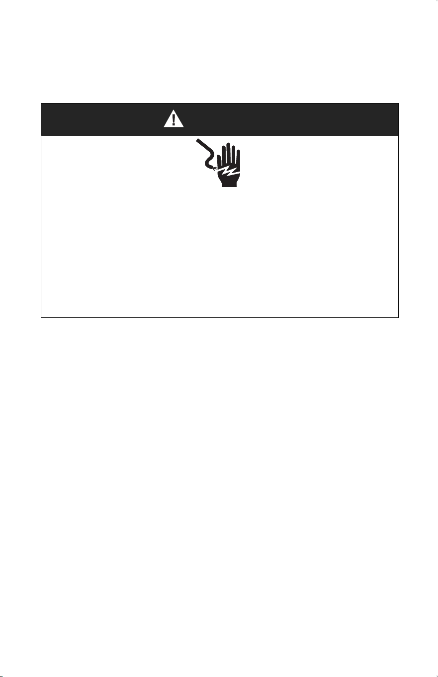
WARNING
Electrical Shock Hazard
Electrically ground range.
Failure to do so can result in death, re or electrical shock.
Electrical Grounding Instructions
This appliance is equipped with a three-prong grounding plug for your protection
against shock hazard and should be plugged directly into a properly grounded recep-
tacle. Do not cut or remove the grounding prong from this plug.
ELECTRICAL REQUIREMENTS
120V/60Hz
This range is equipped with an electronic ignition system that will not operate if plugged
into an outlet that is not properly polarized.
If codes permit and a separate ground wire is used, it is recommended that a qualied
electrical installer determine that the ground path is adequate and wire gauge is in accor-
dance with local codes.
Do not use an extension cord.
WARNING: Improper connection of the equipment-grounding conductor can result in a
risk of electric shock. Check with a qualied electrician or service technician if you are in
doubt as to whether the appliance is properly grounded. Do not modify the power supply
cord plug. If it will not t the outlet, have a proper outlet installed by a qualied electri-
cian.
13

ELECTRICAL REQUIREMENTS - U.S.A. ONLY
Be sure that the electrical connection and wire size are adequate and in conformance
with the National Electrical Code, ANSI/ NFPA No. 70-latest edition and all local codes
and ordinances.
A copy of the above code standards can be obtained from:
National Fire Protection Association
1 Batterymarch Park
Quincy, MA 02169
Electrical Connection
• Check local codes and consult gas supplier. Check existing electrical supply and gas
supply. It is recommended that all electrical connections be made by a licensed, quali-
ed electrical installer.
• Range must be connected to the proper electrical voltage and frequency as specied
on the model/serial rating plate. The plate is located behind the oven door on the oven
frame. Refer to the illustrations in the “Location Requirements” section.
• A 120 volt, 60 Hz, AC only, 15-amp fused, electrical circuit is required. A time- delay
fuse or circuit breaker is also recommended. It is recommended that a separate circuit
serving only this range be provided.
• Electronic ignition systems operate within wide voltage limits, but proper ground-
ing and polarity are necessary. Check that the outlet provides 120-volt power and is
correctly grounded.
• This gas range is not required to be plugged into a GFCI (Ground-Fault Circuit Inter-
rupter) outlet. It is recommended that you not plug an electric spark ignition gas range
or any other major appliance into a GFCI wall outlet as it may cause the GFCI to trip
during normal cycling.
• Performance of this range will not be aected if operated on a GFCI-protected circuit.
However, occasional nuisance tripping of the GFCI breaker is possible due to the
normal operating nature of electronic gas ranges.
• The wiring diagram is located on the back of the range in a clear plastic bag.
NOTE: The metal chassis of the range must be grounded in order for the control panel
to work. If the metal chassis of the range is not grounded, no keypads will operate.
Check with a qualied electrician if you are in doubt as to whether the metal chassis of
the range is grounded.
14

ELECTRICAL REQUIREMENTS - CANADA ONLY
Be sure that the electrical connection and wire size are adequate and in conformance
with the CSA Standard C22.1, Canadian Electrical Code, Part 1 - latest edition and all
local codes and ordinances.
A copy of the above code standards can be obtained from:
Canadian Standards Association 178
Rexdale Blvd.
Toronto, ON M9W 1R3 CANADA
Electrical Connection
Check local codes and consult gas supplier. Check existing electrical supply and gas
supply. It is recommended that all electrical connections be made by a licensed, quali-
ed electrical installer.
• Check with a qualied electrical installer if you are not sure the range is properly
grounded.
• A time-delay fuse or circuit breaker is recommended.
• This range is equipped with a CSA International Certied Power Cord intended to be
plugged into a standard 14-50R wall receptacle. Be sure the wall receptacle is within
reach of range’s nal location.
• Do not use an extension cord.
• The wiring diagram is located on the back of the range in a clear plastic bag.
NOTE: The metal chassis of the range must be grounded in order for the control panel
to work. If the metal chassis of the range is not grounded, no keypads will operate.
Check with a qualied electrician if you are in doubt as to whether the metal chassis of
the range is grounded.
15
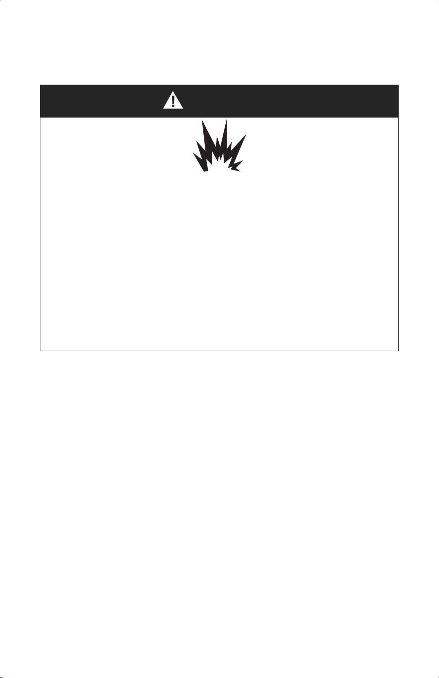
WARNING
Explosion Hazard
Use a new CSA International approved gas supply line.
Install a shut-o valve.
Securely tighten all gas connections.
If connected to LP, have a qualied person make sure gas pressure does not ex-
ceed 14” (36 cm) water column.
Examples of a qualied person include:
• licensed heating personnel
• authorized gas company personnel
• authorized service personnel
Failure to do so can result in death, explosion or re.
GAS SUPPLY REQUIREMENTS
Observe all governing codes and ordinances.
IMPORTANT: This installation must conform with all local codes and ordinances. In the
absence of local codes, installation must conform with American National Standard, Na-
tional Fuel Gas Code ANSI Z223.1 - latest edition or CAN/CGA B149 - latest edition.
IMPORTANT: Leak testing of the range must be conducted according to the manufac-
turer’s instructions.
TYPE OF GAS
Natural Gas:
This range is design-certied by CSA International for use with natural gas or, after
proper conversion, for use with LP gas.
•This range is factory-set for use with Natural gas. The model/serial rating plate located
on the right side oven door trim has information on the types of gas that can be used.
If the types of gas listed do not include the type of gas available, check with the local
gas supplier.
16
LP Gas Conversion:
Conversion must be performed by a qualied service technician. The qualied agency
performing this work assumes the gas conversion responsibility.
No attempt shall be made to convert the appliance from the gas specied on the model/
serial rating plate for use with a dierent gas without consulting the serving gas supplier.
See “GAS CONVERSION” section.
GAS SUPPLY LINE
Provide a gas supply line of 3/4” (1.9 cm) rigid pipe to the range location. A smaller size
pipe on longer runs may result in insucient gas supply. Pipe-joint compounds that resist
the action of LP gas must be used. With LP gas, piping or tubing size can be 1/2” (1.3
cm) minimum. Usually, LP gas suppliers determine the size and materials used in the
system.
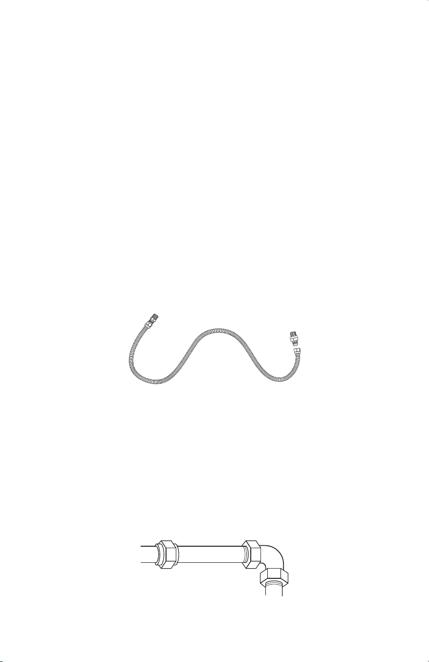
Flexible metal appliance connector:
•If local codes permit, a new CSA design-certied, 4 - 5 ft (122 - 152.4 cm) long, 1/2”
(1.3 cm) or 3/4” (1.9 cm) I.D., exible metal appliance connector may be used for
connecting range to the gas supply line.
• A 1/2” (1.3 cm) male pipe thread is needed for connection to the female pipe threads of
the inlet to the appliance pressure regulator.
• Do not kink or damage the exible metal tubing when moving the range.
Rigid pipe connection:
The rigid pipe connection requires a combination of pipe ttings to obtain an in-line con-
nection to the range. The rigid pipe must be level with the range connection. All strains
must be removed from the supply and fuel lines so range will be level and in line.
17
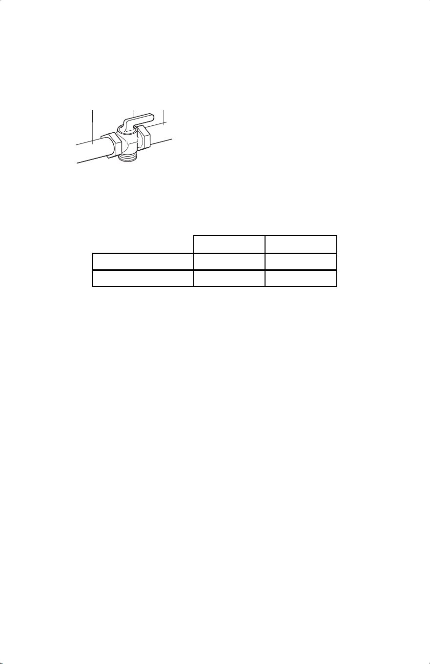
Gas shuto valve:
A manual gas line shut-o valve must be installed in an easily accessible location. Do
not block access to shut-o valve. The valve is for turning on or shutting o gas to the
range.
a b c
a
b
c
Gas Supply Line
Shuto Valve “Open” Position
To Range
GAS PRESSURE REGULATOR
The gas pressure regulator supplied with this range must be used. The inlet pressure
to the regulator should be as follows for proper operation:
Contact local gas supplier if you are not sure about the inlet pressure.
Burner Input Requirements
Input ratings shown on the model/serial rating plate are for elevations up to 2,000 ft
(609.6 m).
For elevations above 2,000 ft (609.6 m), ratings are reduced at a rate of 4% for each
1,000 ft (304.8 m) above sea level (not applicable for Canada).
GAS SUPPLY PRESSURE TESTING
Gas supply pressure for testing regulator must be at least 1” (2.5 cm) water column
pressure above the manifold pressure shown on the model/serial rating plate.
Line pressure testing above 0.5 psi gauge (14” WCP)
The range and its individual shuto valve must be disconnected from the gas supply
piping system during any pressure testing of that system at test pressures in excess of
0.5 psi (3.5 kPa).
Line pressure testing at 0.5 psi gauge (14” WCP) or lower
The range must be isolated from the gas supply piping system by closing its individual
manual shuto valve during any pressure testing of the gas supply piping system at test
pressures equal to or less than 1/2 psi (3.5 kPa).
18
Natural gas LP gas
Minimum pressure 4” WCP 10” WCP
Maximum pressure 7” WCP 11” WCP
Installation Instructions
IMPORTANT: This appliance shall be installed only by authorized persons and in
accordance with the manufacturer’s installation instructions, local gas tting regulations,
municipal building codes, electrical wiring regulations, local water supply regulations.
UNPACK RANGE
WARNING
Excessive Weight Hazard
Use two or more people to move and install range.
Failure to do so can result in back or other injury.
1.Remove shipping materials, tape and lm from the range. Keep cardboard bottom under
range. Do not dispose of anything until the installation is complete.
2.Remove oven racks and parts package from oven and shipping materials. 3.To remove
cardboard bottom, rst take 4 cardboard corners from the carton. Stack one cardboard
corner on top of another. Repeat with the other 2 corners. Place them lengthwise on the
oor behind the range to support the range when it is laid on its back.
4.Using two or more people, rmly grasp the range and gently lay it on its back on the
cardboard corners.
5.Remove cardboard bottom.
NOTES:
• The leveling legs can be adjusted while the range is on its back.
• To place range back up into a standing position, put a sheet of cardboard or hardboard
on the oor in front of range to protect the ooring. Using two or more people, stand
range back up onto the cardboard or hardboard.
19
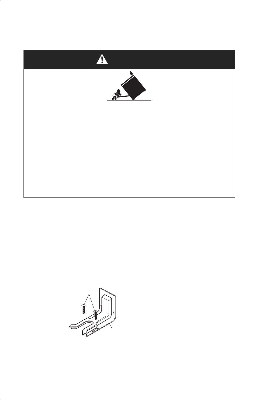
WARNING
Tip Over Hazard
• A child or adult can tip the range and be killed.
• Install anti-tip bracket to oor or wall per installation instructions.
• Slide range back so rear range foot is engaged in the slow of the anti-top bracket.
• Re-engage the anti-tip bracket if range is moved.
• Do not operate the range without anti-tip bracket installed and engaged.
• Failure to follow these instructions can result in death or serious burns to children
and adults.
IMPORTANT:
• An anti-tip bracket is provided with the range. The anti-tip bracket uses a rear range
foot to secure the range to the oor or wall.
• Attach the anti-tip bracket to the oor or wall so that the rear range foot will be
centered within the bracket when the range is pushed into its nal position.
1.Remove the anti-tip bracket and screws from the parts bag.
a
a
16 x 1⁵⁄₈” Screws (2) An-
ti-tip Bracket
b
INSTALL ANTI-TIP DEVICE
b
NOTE: The anti-tip bracket must be securely mounted to the suboor or wall. The
ooring’s thickness may require longer screws to anchor bracket to suboor.
20
e
d
c
b
c
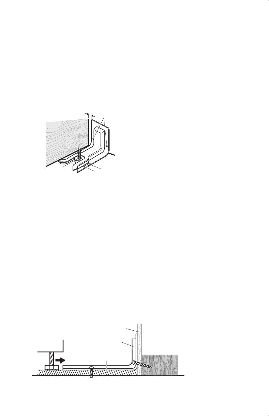
2.Place the bracket so that the back of the bracket is against the rear wall and the side
edge of the bracket is 3/8” to 1/2” from the adjacent cabinet.
NOTE: If there is no adjacent cabinet, place the bracket so that the edge of the bracket
is 3/8” to 1/2” in from the range side panel. If the countertop overhangs the cabinet,
oset the bracket from the cabinet by the depth of the overhang plus an additional
3/8” to 1/2”.
3.Using the anti-tip bracket as a template, mark the two holes for either a Floor Wood,
Floor Concrete, or Wall installation, as shown.
a
a: Distance from Adjacent Cabinet
(3/8” to 1/2” [0.95 cm to 1.27 cm])
b: Wall Holes
c: Concrete Floor Holes
d: Wood Floor Holes
e: Rear Range Foot
4.Drill two pilot holes where marked. Follow the instructions specic to your construc-
tion.
NOTE: A nail or awl may be used to create a pilot hole, if a drill is not available.
For concrete construction 1/4” x 1 ½ “ Lag Bolts and 1/2” O.D. Sleeve Anchors are
required.
Wood
• Floor - Drill a 1/8” pilot hole, as shown.
NOTE: Contact a qualied oor covering installer for the best procedure for drill-
ing mounting holes through your type of oor covering.
• Wall - Drill an angled 1/8” pilot hole, as shown. Concrete
• Drill the size hole recommended for the anchors into the concrete at the center of
the holes identied as Floor Concrete or Wall.
a b
21
a
b
c
Wall
Anti-tip
Bracket
Floor
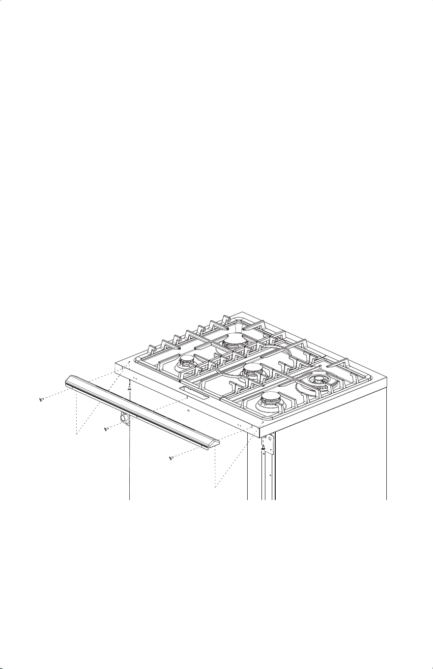
5.Install the anti-tip bracket.
Wood
• Using the two screws (provided) fasten the anti-tip bracket to the oor or wall.
NOTE: The screw must enter wood or metal.
Concrete
• Insert the sleeve anchor into the drilled holes and then insert the lag bolts through
the anti-tip bracket and into the oor or wall. The bolts must be properly tightened
as recommended for the hardware.
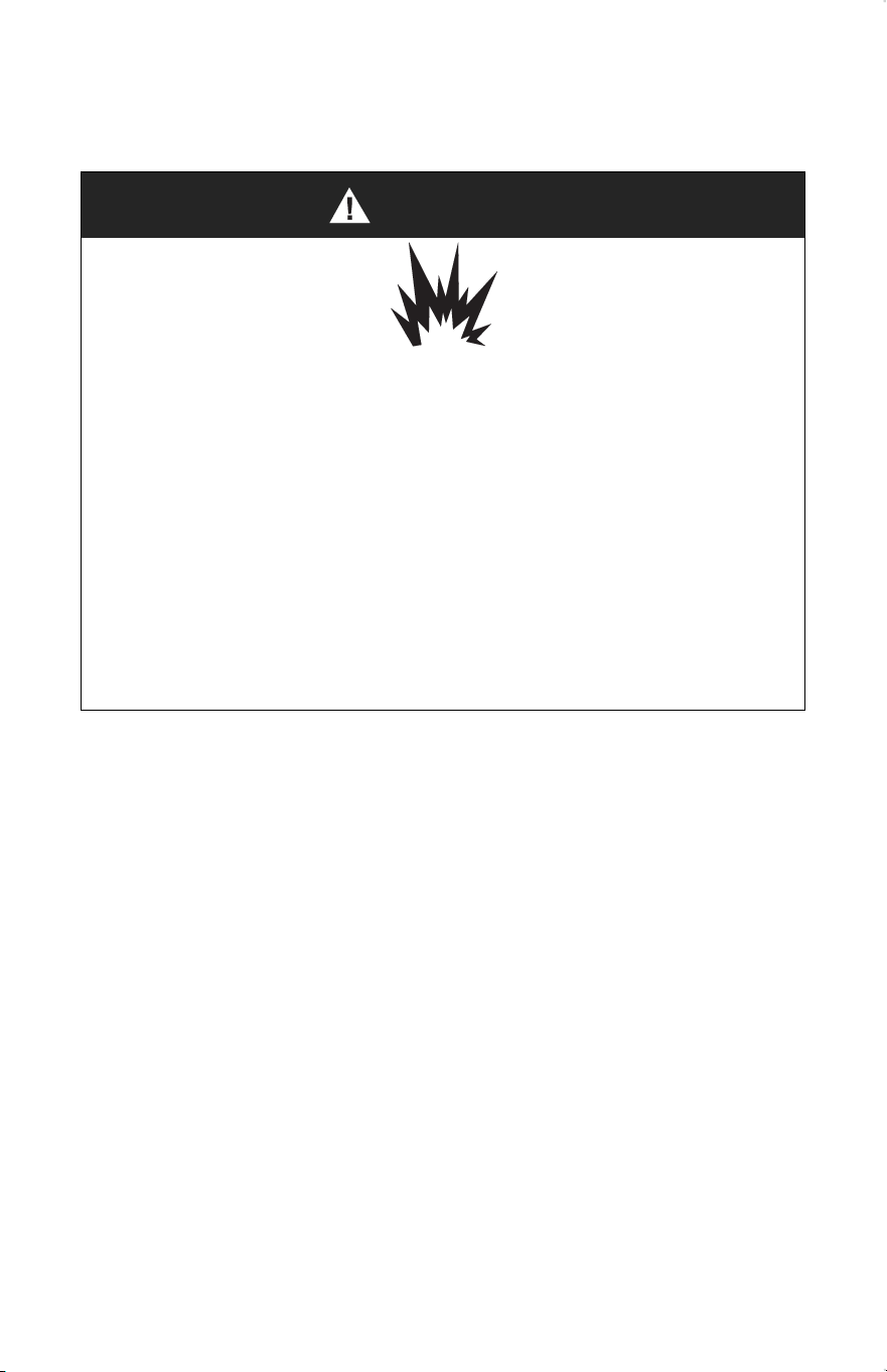
INSTALL BACKSPLASH
•Install the backsplash to rear of range with the screws provided.
22
WARNING
Explosion Hazard
Use a new CSA International approved gas supply line.
Install a shut-o valve.
Securely tighten all gas connections.
If connected to LP, have a qualied person make sure gas pressure does not ex-
ceed 14” (36 cm) water column.
Examples of a qualied person include:
• licensed heating personnel
• authorized gas company personnel
• authorized service personnel
Failure to do so can result in death, explosion or re.
GAS CONNECTION
This appliance shall be installed only by authorized persons and in accordance with the
manufacturer’s installation instructions, local gas tting regulations, municipal building
codes, electrical wiring regulations, local water supply regulations.
This range is factory-set for use with Natural gas. To use this range with Propane gas, see
the “GAS CONVERSION section before connecting this range to the gas supply. Gas
conversions from Natural gas to Propane gas or from Propane gas to Natural gas must be
done by a qualied installer.
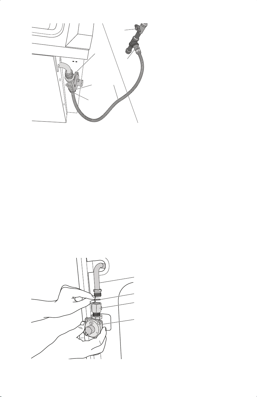
TYPICAL FLEXIBLE CONNECTION
1.Apply pipe-joint compound made for use with LP gas to the smaller thread ends of the
exible connector adapters.
2.Attach one adapter to the gas pressure regulator and the other adapter to the gas shuto
valve. Tighten both adapters, being certain not to move or turn the gas pressure regula-
tor.
23
a
b
d
c
e
d
2. Using a pipe wrench to tighten, connect the gas supply to the range.
a
b
c
d
a
b
c
d
Gas Line from Range
Washer (provided)
Adapter (provided)
Gas Pressure Regulator
(provided)
a: Adapter (provided) Gas
b: Pressure Regulator Gas
c: Supply Line
d: Adapters (From Gas
Supply Line Kit)
e: Gas Shuto Valve
3.Use a 15/16” (2.4 cm) combination wrench and channel lock pliers to attach
the exible connector to the adapters. Check that connector is not kinked.
TYPICAL RIGID PIPE CONNECTION
A combination of pipe ttings must be used to connect the range to the existing gas line.
Your connections may be dierent, according to the supply line type, size and location.
1.Apply pipe-joint compound made for use with LP gas to all pipe thread connections.
24
WARNING
Electrical Shock Hazard
Disconnect power before servicing.
Plug into a grounded 3-prong outlet.
Do not use an adapter or an extension cord.
Failure to do so can result in death, re, or electrical shock
COMPLETE CONNECTION
1.Open the manual shuto valve in the gas supply line. The valve is open when the
handle is parallel to the gas pipe.
2.Test all connections by brushing on an approved noncorrosive leak-detection solution.
If bubbles appear, a leak is indicated. Correct any leak found.
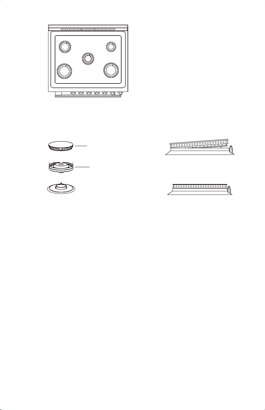
3.Remove, if any, packaging tapes securing the burners on the surface. If the cooktop
burner bases and caps are not pre-installed, remove them from package containing
parts, align and place the burner bases and caps accordingly.
25
C D
C
A B
Base
Cap
Note: Align notches in burner caps with pins in burner base. Burner caps should be
level when properly positioned. If burner caps are not properly positioned, surface
burners will not light.
Auxiliary Burner
Semi Rapid Burner
Rapid Burner
4.Place burner grates over burners and caps.
5.Plug in range or reconnect power.
26
Incorrectly Positioned
Correctly Positioned
MAX
High flame
Low f
lame
If burners do not light properly:
1.Turn burner control knob to the “OFF” position.
2.Check that the range is plugged in. Check that the circuit breaker has not tripped or the
household fuse has not blown.
3.Check that the gas shuto valves are set to the “open” position. 4.Check that
burner caps are properly positioned on burner bases.
To adjust standard burner:
IMPORTANT: Adjustments must be made with two other burners in operation on a medi-
um setting. This prevents the upper row of ames from being set too low, resulting in the
ame being extinguished when other burners are turned on.
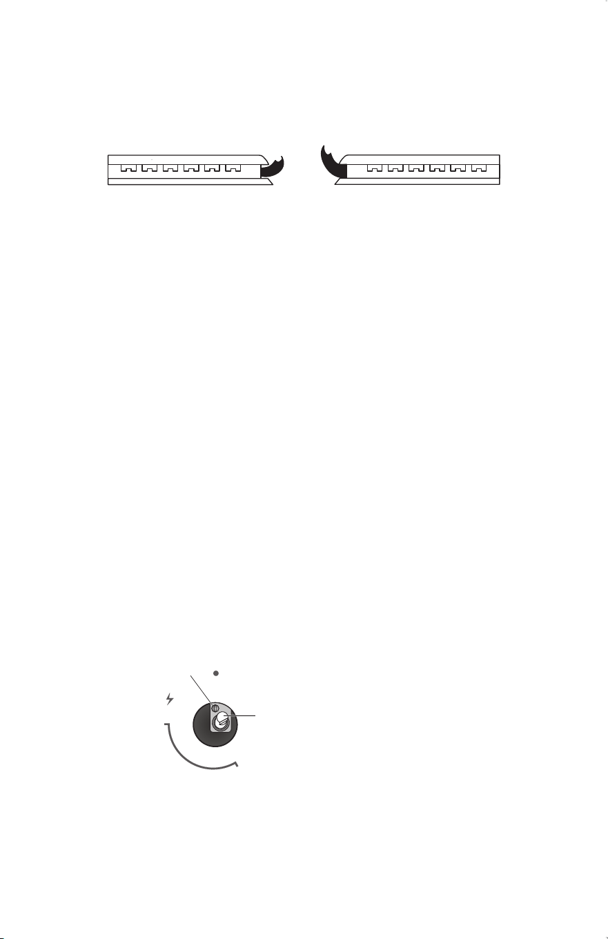
The ame can be adjusted using the adjustment screw in the center of the valve stem. The
valve stem is located directly behind the control knob.
1.Light the burner and turn the knob to the lowest setting (MIN). 2.Pull and
remove the control knob.
3.Insert a small, at-blade screwdriver into the adjustment screw, and slowly turn the
screw until the ame appearance is correct.
• Open the valve more if the ames are too small or uttered.
• Close the valve more if the ames are too large.
OFF
b
MIN
ADJUST FLAME HEIGHT
Check and adjust the height of top burner ames. The cooktop “low” burner ame should
be a steady blue ame approximately 1/4” (6 mm) high. Propane gas ames have a
slightly yellow tip.
a
a
b
Adjustment Screw
Control Knob Stem
4.Replace the control knob.
5.Test and check the ame by turning the control knob from the lowest to the highest
settings.
27

NOTE: For burners (on some models) with safety valve, make sure that the regulation
obtained is sucient to maintain heating of the thermocouple. If it is not, increase the
minimum ame.
ABNORMAL OPERATION
ANY OF THE FOLLOWING ARE CONSIDERED TO BE ANBORMAL OPERATION
AND MAY REQUIRE SERVICING:
• Yellow tipping of the hob burner ame
• Sooting up of cooking utensils.
• Burners not igniting properly.
• Burners failing to remain lit.
• Burners extinguished by oven door.
• Gas valves, which are dicult to turn.
IN CASE THE APPLIANCE FAILS TO OPERATE CORRECTLY, CONTACT THE
AUTHORIZED SERVICE PROVIDE IN YOUR AREA.
THE BURNERS REQUIRE NO REGULATION OF THE PRIMARY AIR.
LEVEL RANGE
IMPORTANT: Do not operate the range if its rear foot is not completely engaged in
the anti-tip bracket. Never completely remove the leveling legs or the range will not be
secured to the anti-tip device properly.
1.Slide range into nal location, making sure rear leveling leg slides into the anti- tip
bracket. Leave a 1” (2.5 cm) gap between the back of the range and the back wall.
2.Check that the range is level by placing a level on the oven bottom. If needed, use a
wrench to adjust the height of the leveling legs until the range is level from side to
side and from front to back.
NOTE: The range must be level for optimum cooking and baking performance.
28
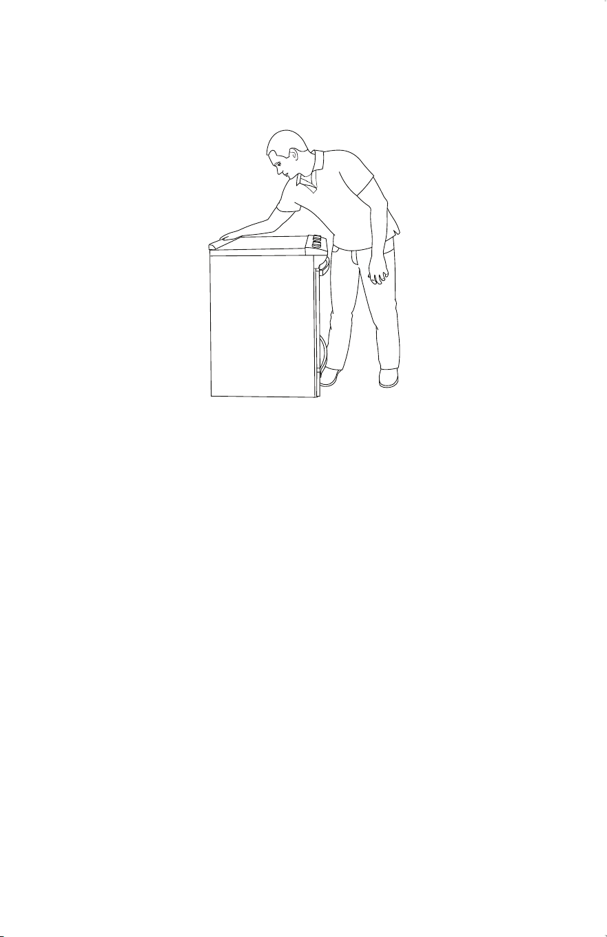
VERIFY ANTI-TIP BRACKET ENGAGEMENT
1.Place the outside of your foot against the bottom of the front panel to keep
the range from moving, and then grasp the back of the range, as shown.
2.Slowly attempt to tilt the range forward.
• If you encounter immediate resistance, the range foot is engaged in the anti-tip
bracket. Range installation is completed.
• If the rear of the range lifts more than 1/2” (1.3 cm) o the oor without resistance,
stop tilting the range and lower it gently back to the oor. The range foot is not
engaged in the anti-tip bracket. Proceed to Steps 3 and 4.
IMPORTANT: If there is a snapping or popping sound when tilting the range, the
range may not be fully engaged in the bracket. Check to see if there are obstruc-
tions keeping the range from sliding to the wall or keeping the range foot from
sliding into the bracket. Verify that the bracket is held securely in place by the
mounting screws.
3.Slide the range forward, and verify that the anti-tip bracket is securely attached to the
oor or wall.
4.Slide range back so the rear range foot is inserted into the slot of the anti-tip bracket.
IMPORTANT: If the range is pulled away from the wall for any reason, always verify
anti-tip bracket engagement again.
29
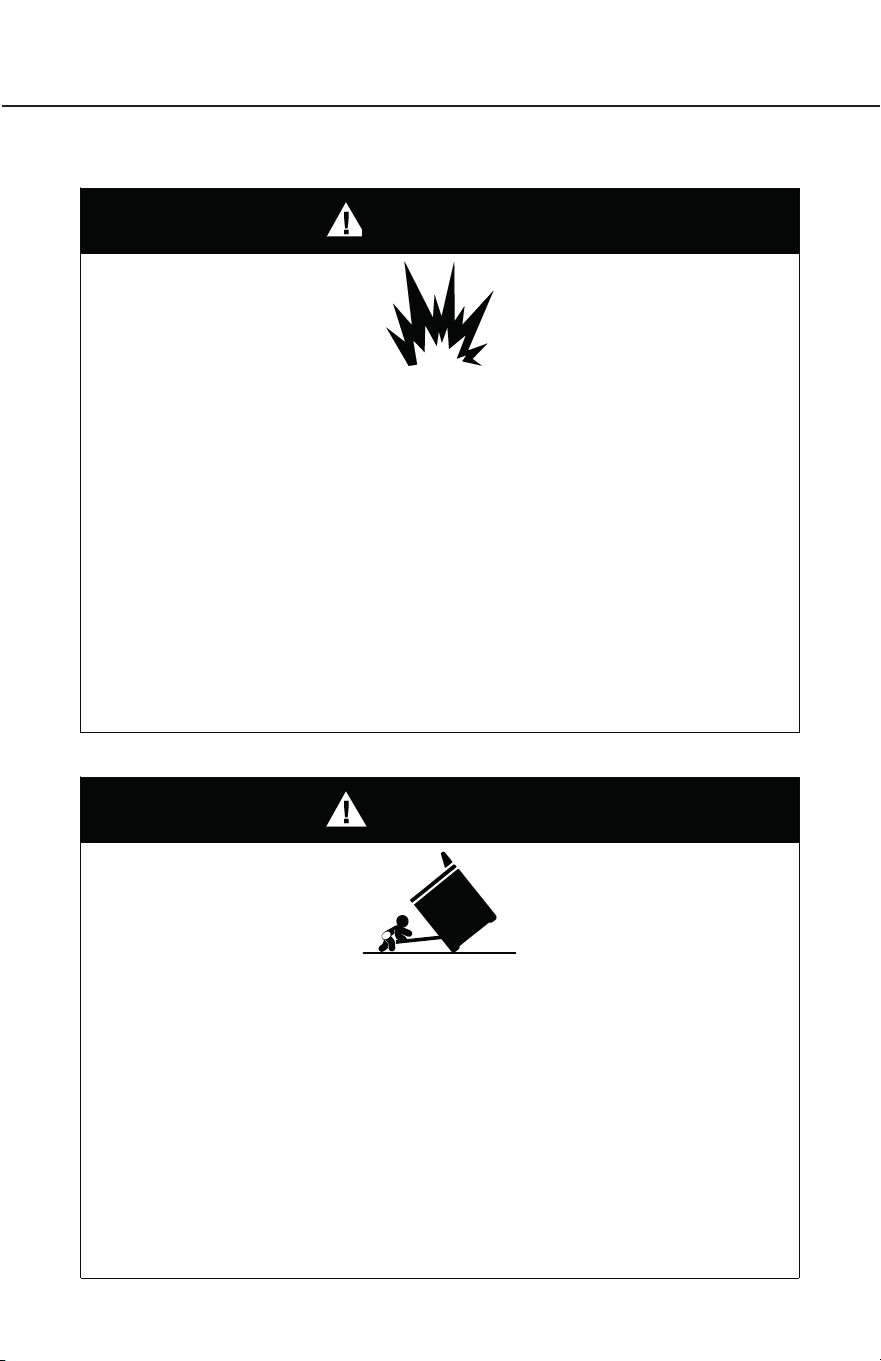
WARNING
FIRE AND EXPLOSION HAZARD
• Use a new CSA International approved gas supply line and install a shut-o valve
for new installations.
• Securely tighten all gas connections.
• If connected to LP, have a qualied person make sure gas pressure does not exceed
the maximum pressure listed in the “Gas Supply Requirement” section.
• Examples of a qualied person include:
- licensed heating personnel
- authorized gas company personnel
- authorized service personnel
• Failure to do so can result in death, explosion or re.
WARNING
TIP OVER HAZARD
• A child or adult can tip the range and be killed.
• Install anti-tip bracket to oor or wall per installation instructions.
• Slide range back so rear range foot is engaged in the slot of the anti-tip bracket.
• Re-engage the anti-tip bracket if range is moved.
• Do not operate the range without anti-tip bracket installed and engaged.
• Failure to follow these instructions can result in death or serious burns to children
and adults.
30
GAS CONVERSION
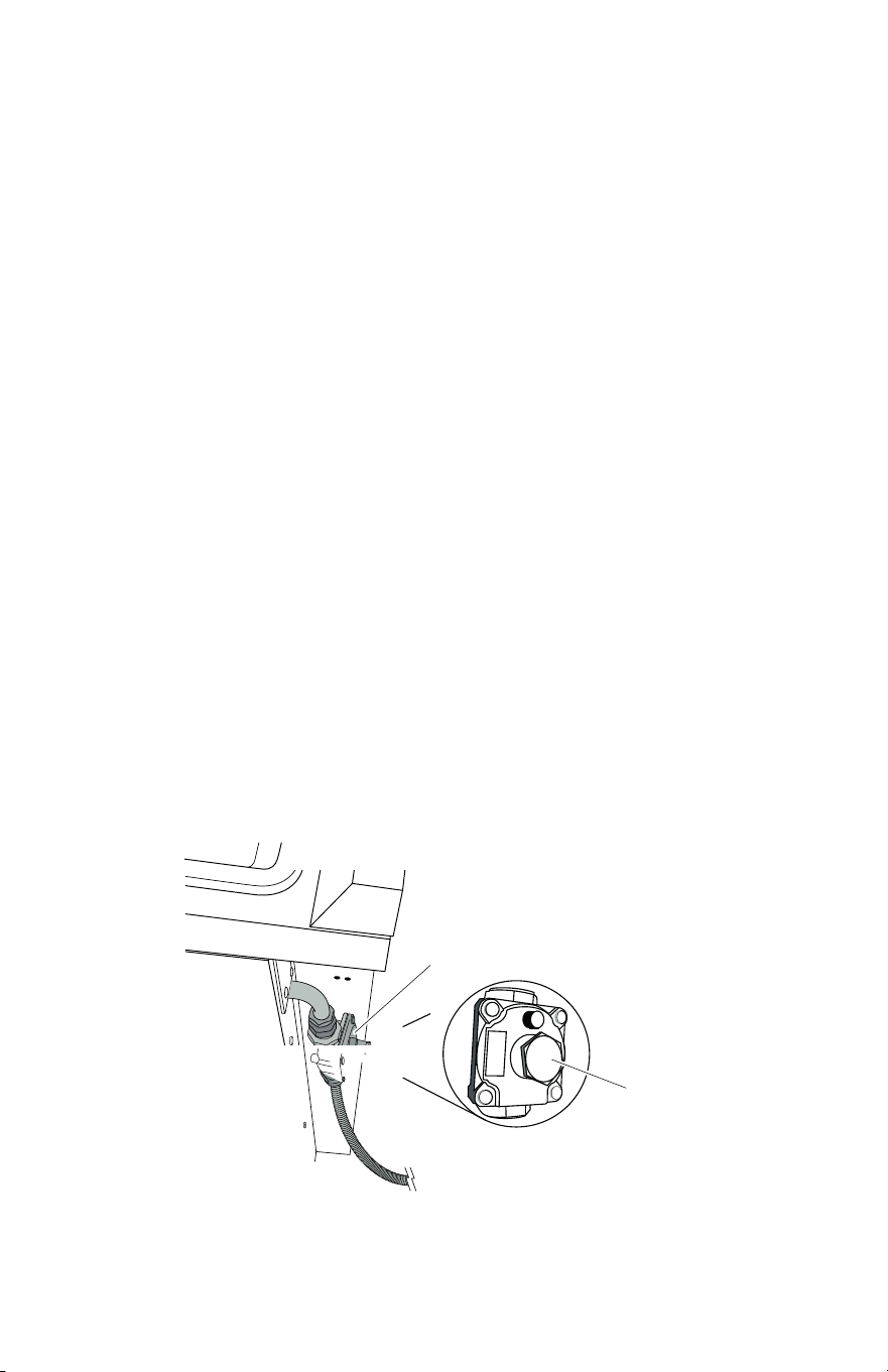
Gas pressure regulator
Metal cover
This range is factory-set for use with Natural gas (NG).
IMPORTANT: Gas conversions must be done by a qualied service technician in
accordance with the manufacturer’s instructions and all codes and requirements of the
authority having jurisdiction. The qualied agency performing this work assumes the
gas conversion responsibility.
CONVERT GAS PRESSURE REGULATOR
1. Turn manual shuto valve to the closed position.
2. Unplug range or disconnect power.
3. Move the range out from the wall or installation space. Locate the gas pressure
regulator on the back of the range.
IMPORTANT: Do not remove the gas pressure regulator.
4. Unscrew the metal cover in the center of the gas pressure regulator with a
wrench.
31
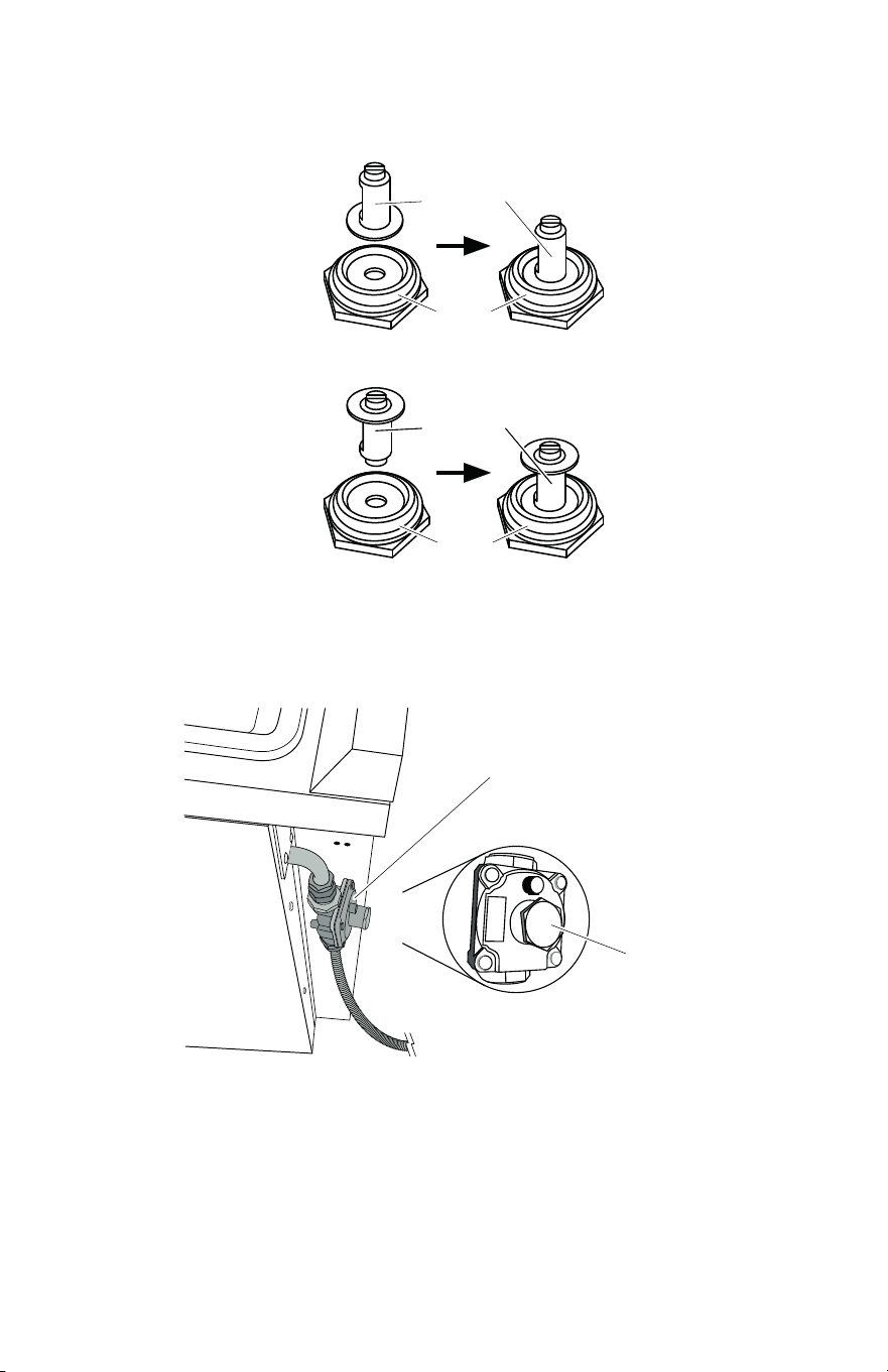
Gas pressure regulator
Metal cover
Regulator
cap
Metal
cover
Regulator
cap
Metal
cover
5. Remove the regulator cap on the metal cover. Orient the regulator cap
for the fuel type being used and place it back into the metal cover.
NG Natural gas
LP Propane gas
orientation
6. Screw and tighten the metal cover back into the gas pressure regulator
with a wrench.
32

CONVERT SURFACE BURNERS
IMPORTANT: Make sure to save the orices that have just been replaced in the
conversion.
Tool Needed
• 9/32” (7 mm) nut driver
NG/LP Orice Chart for Surface and Oven Burners
33
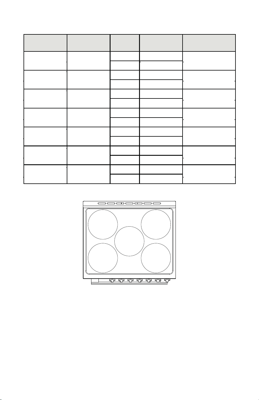
6,000 BTU
NG: 1.18
LP: 0.72
12,000 BTU
NG: 1.70
LP: 1.05
6,000 BTU
NG: 1.18
LP: 0.72
3,500 BTU
NG: 0.90
LP: 0.56
12,000 BTU
NG: 1.70
LP: 1.05
34
Burner Placement
Orice
Type
Orice Size
(mm)
Burner Rating
Rapid Front Left
NG 1.70
12,000 BTU
LP 1.05
Rapid Front Right
NG 1.70
12,000 BTU
LP 1.05
Semi Rapid Center
NG 1.18
6,000 BTU
LP 0.72
Semi Rapid Rear Left
NG 1.18
6,000 BTU
LP 0.72
Auxiliary Rear Right
NG 0.90
3,500 BTU
LP 0.56
Broil Oven Top
NG 1.40
8,500 BTU
LP 0.83
Bake Oven Bottom
NG 1.85
14,000 BTU
LP 1.10
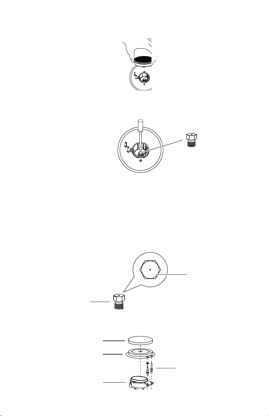
35
091
Orice
1. If installed, remove the burner grates, burner caps, and the burner bases.
2. Remove the existing orices with a 9/32” (7 mm) nut driver.
3. Replace the orices with the correct fuel type orices. Gas orices are
stamped with a size number. Refer to the orice chart earlier for correct Natural
gas and LP gas orice sizes and proper placement.
IMPORTANT: Keep and store the orices that have just been replaced in case of
re-installation with another gas.
Burner base
Orice Size
(091 - Denotes 0.91 mm)
4. Replace the burner base, burner caps, and burner grates.
Burner cap
Burner base
Orice holder
Igniter
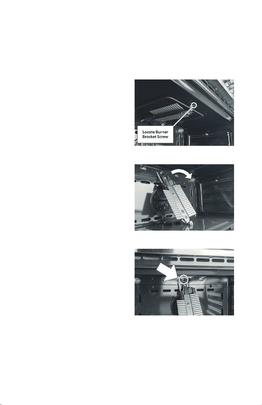
CONVERT OVEN BURNERS
This product cannot be converted to Natural gas or LP gas by adjusting or tightening
the oven orices. The orices must be replaced.
Converting Broil Burner
1. Unscrew Front Bracket
Locate the bracket at the front of the
broiler. Remove the screw.
2. Remove the Burner
Carefully slide the burner forward and
out of the socket, without severing or
damaging the wire attached. Carefully
lay the burner down as shown in the
image to the right.
3. Change the Burner Orice
With the burner out of the way look
for the orice as shown. Continue with
changing the orice.
36
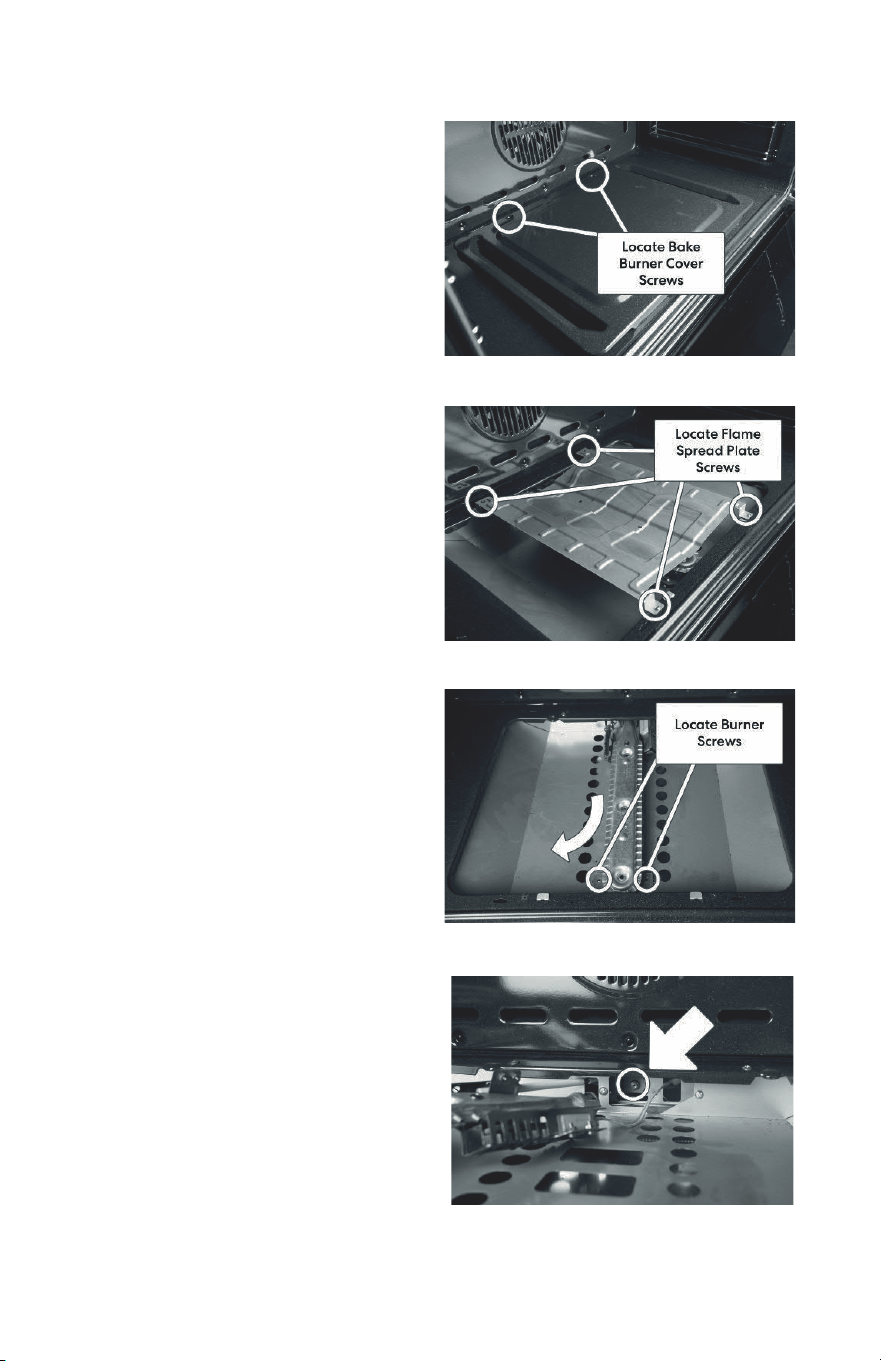
Converting Bake Burner
1. Remove Bake Burner Cover
Open your oven door and unscrew the
back two screws of bake burner cover.
Remove the bake burner cover.
2. Remove Flame Spread Plate
Unscrew the four screws of the ame
spread plate. Remove the ame spread
plate.
3. Slide Out Burner
Unscrew the front two screws holding
the burner in place. Slide out the burner
up and towards oven door out of the
socket, careful not to sever or pull on
the wire.
4. Change the Burner Orice
Move the burner carefully to gain ac-
cess to the burner orice, careful not to
sever or pull on the wire. Proceed with
changing the orice.
37

COMPLETE GAS CONVERSION
1. Open shuto valve in the gas supply line.
2. Plug in range or reconnect power.
• Refer to “Gas Connection” section in the “Installation Instructions” section for
proper connection of the range to the gas supply.
• Refer to “Complete Installation” section to complete this procedure.
• Refer to the “Adjust Flame Height” section for surface burner ame adjustments.
IMPORTANT: You may have to adjust the low setting for each cooktop burner.
38

39

ENGLISH
Read these instructions carefully before using your appliance, and keep it carefully.
If you follow the instructions, your appliance will provide you with many years of good service.
MODEL NUMBER SERIES
FFSGS1116-30 | FFSGS1116-30BLK | FFSGS1116-30WHT
INSTRUCTION MANUAL
GAS RANGE


3
TABLE OF CONTENTS
Customer Care 5
Warning 6
Important Safety 7
Names of Parts and Accessories 9
Installations:
• Anti-tip Bracket ................................................................
• Handle .............................................................................
10
11
Control Panel 12
Operating Instruction
• Cookware .........................................................................
• Oven Control......................................................................
13
14
Care and Maintenance 16
Troubleshooting 17
Warranty 20
4
MODEL NUMBER SERIES
FFSGS1116-30 | FFSGS1116-30BLK | FFSGS1116-30WHT
GAS RANGE
5
Thank you for purchasing a Frono product. Please read the entire instruction manual before operating your new
appliance for the first time. Whether you are an occasional user or an expert, it will be beneficial to familiarize yourself
with the safety practices, features, operation and care recommendations of your appliance.
Both the model and serial number are listed inside the product. For warranty purposes, you will also need the date of
purchase .
Record this information below for future reference.
Services in Canada and Untied States
Keep the instruction manual handy to answer your questions. If you don’t understand something or need more
assistance, please visit our website for fast support. Please provide us your name, number, address,serial number
of the product that troubleshooting, proof of purchase, and a short description of the issue. A customer service
representative will contact you as soon as possible. All warranty work needs to be authorized by FORNO customer
service. All our authorized service providers are carefully selected and rigorously trained by us.
Product Information Service Information
Model Number : _________________________________________
Use these numbers in any
correspondence or services calls
concerning your product.
If you received a damaged product,
immediately contact Forno.
To save time and money, before
you call for serviced, check the
troubleshooting guide. It listed the
causes of minor operation problems
that you can correct yourself.
Serial Number : __________________________________________
Date of Purchase :________________________________________
Purchase Address And Phone : _____________________________
_______________________________________________________
_______________________________________________________
Customer Care
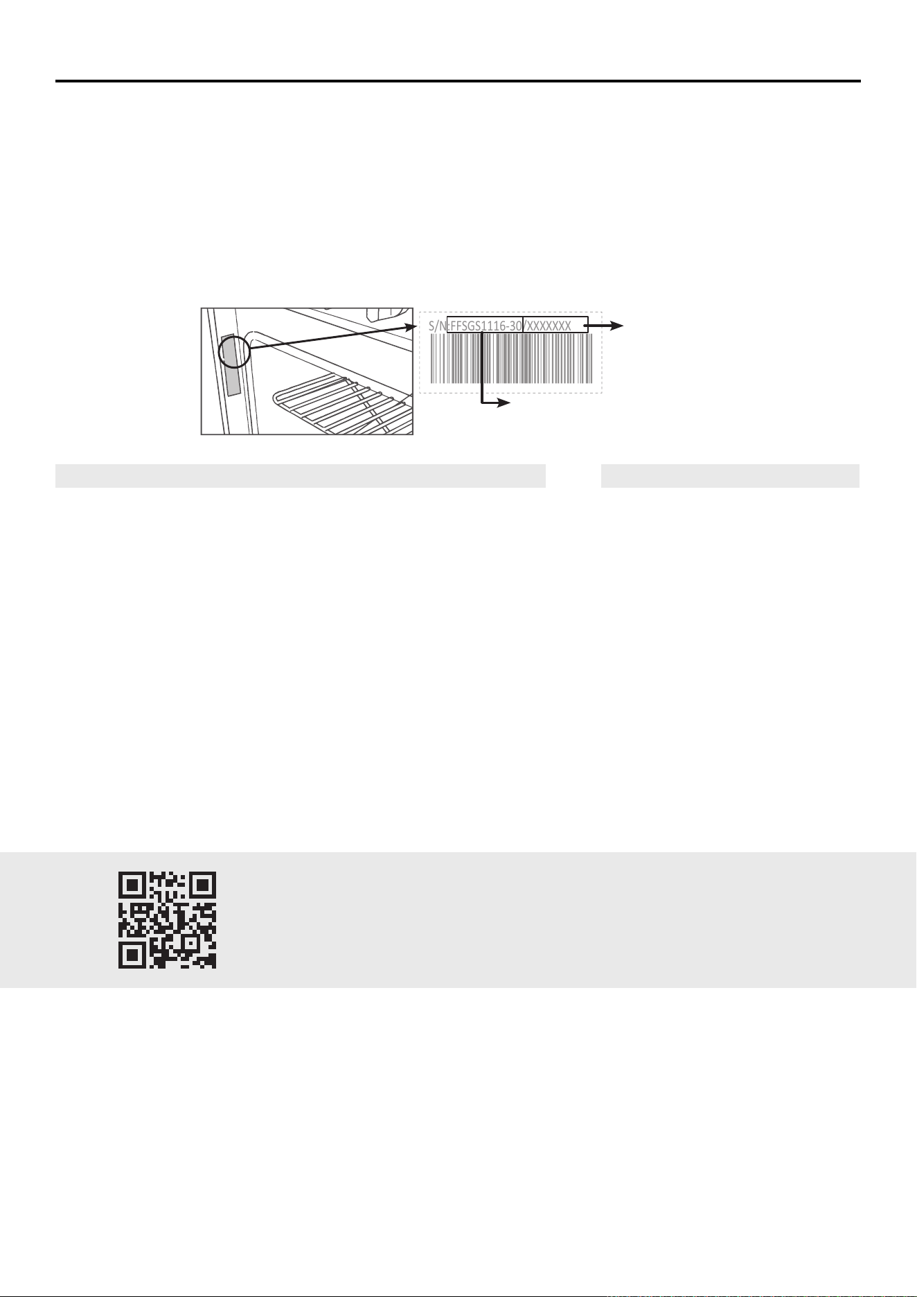
Model Number
Serial Number
Model And Serial Number Location
“Need some quick help? Simply scan the qr code and get access
to our fast support form. We’re always here to assist you with any
questions or concerns you may have. So, don’t hesitate to reach out!”
S/N:FFSGS1116-30/XXXXXXX
6
WARNING
FOR YOUR SAFETY
Your safety and the safety of others are very important.
We have provided many important safety messages in this manual and on your appliance. Always read and obey all
safety messages.
This is the safety alert symbol. This symbol alerts you to potential hazards that can kill or hurt you
and others. Al l safety messages will follow the safety alert symbol and either the word “DANGER,”
“WARNING” or “CAUTION.” These words mean:
• You can be killed or seriously injured if you don’t immediately follow instructions.
• You can be killed or seriously injured if you don’t follow instructions.
• A potentially hazardous situation which, if not avoided, could result in minor or
moderate injury.
All safety messages will tell you what the potential hazard is, tell you how to reduce the chance of injury, and tell you
what can happen if the instructions are not followed.
DANGER
WARNING
CAUTION
WARNING : This product can expose you to chemicals including [Lead, lead
and lead compound, which is [are] known to the state of California to cause
cancer and birth defects or other reproductive harm. For more information go
to www.P65Warning.ca.gov.
In the State of Massachusetts, the following installation instructions apply:
• Installations and repairs must be performed by a qualied or licensed contractor,
plumber, or gas tter qualied or licensed by the State of Massachusetts.
• If using a ball valve, it shall be a T-handle type.
• A exible gas connector, when used, must not exceed 3 feet.
7
Important Safety Instructions
WARNING
Fire Hazard
If the information in this manual is not followed exactly, a re or explosion may result causing property damage, personal injury or death.
- Do not store or use gasoline or other ammable vapors and liquids in the vicinity of this or any other appliance.
- WHAT TO DO IF YOU SMELL GAS
• Do not try to light any appliance.
• Do not touch any electrical switch.
• Do not use any phone in your building.
• Clear the room, building, or area of all occupants.
• Immediately call your gas supplier from a neighbor’s phone. Follow the gas supplier’s instructions.
• If you cannot reach your gas supplier, call the re department.
- Installation and service must be performed by a qualied installer, service agency or the gas supplier.
WARNING
NEVER OPERATE THE TOP SURFACE COOKING SECTION OF THIS APPLIANCE UNATTENDED.
• Failure to follow this warning statement could result in re, explosion, or burn hazard that could cause property
damage, personal injury, or death.
• If a re should occur, keep away from the appliance and immediately call your re department.
DO NOT ATTEMPT TO EXTINGUISH AN OIL/GREASE FIRE WITH WATER
WARNING
Tip Over Hazard
• A child or adult can tip the range and be killed.
• Install anti-tip bracket to oor or wall per installation instructions.
• Slide range back so rear range foot is engaged in the slow of the anti-tip bracket.
• Re-engage the anti-tip bracket if range is moved.
• Do not operate the range without anti-tip bracket installed and engaged.
• Failure to follow these instructions can result in death or serious burns to children and adults.
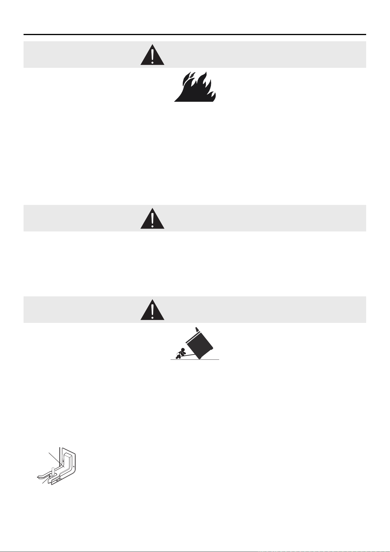
MAKING SURE THE ANTI-TIP BRACKET IS INSTALLED :
• Slide range forward.
• Look for the anti-tip bracket securely attached to oor and wall.
• Slide range back so rear range foot is under anti-tip bracket.
WARNING:
Gas leaks cannot always be detected by smell.
Gas suppliers recommend that you use a gas detector approved by UL or CSA.
For more information, contact your gas supplier.
WARNING: Do not install a ventilation system that blows air downward toward this cooking appliance. This type of
ventilation system may cause ignition and combustion problems with this cooking appliance resulting in personal injury or
unintended operation.
Anti-tip
Bracket
Range
Foot

8
Important Safety Instructions
• WARNING: TO REDUCE THE RISK OF TIPPING OF THE
RANGE, THE RANGE MUST BE SECURED BY PROPERLY
INSTALLED ANTI-TIP DEVICES. TO CHECK IF THE
DEVICES ARE INSTALLED PROPERLY, SLIDE THE RANGE
COMPLETELY FORWARD, LOOK FOR THE ANTI-TIP
BRACKET SECURELY ATTACHED TO THE FLOOR BEHIND
THE RANGE, AND SLIDE RANGE COMPLETELY BACK UNTIL
THE REAR RANGE FOOT IS UNDER ANTI-TIP BRACKET.
• WARNING: NEVER use this appliance as a space heater
to heat or warm the room. Doing so may result in carbon
monoxide poisoning and overheating of the oven.
• WARNING: NEVER cover any slots, holes, or passages
in the oven bottom or cover an entire rack with materials
such as aluminum foil. Doing so blocks airow through
the oven and may cause carbon monoxide poisoning.
Aluminum foil linings may also trap heat, causing a re
hazard.
• CAUTION: Do not store items of interest to children in
cabinets above a range or on the back guard of a range
–children climbing onto the range to reach items could be
seriously injured.
• DO NOT LEAVE Children Alone –Children should not be
left alone or unattended in areas where the range is in
use. They should never be allowed to sit or stand on any
part of the range.
• Wear Proper Apparel – Loose-tting or hanging garments
should never be worn while using the range.
• User Servicing – Do not repair or replace any part of the
range unless specically recommended in the manual. All
other servicing should be referred to a qualied technician.
• Storage in or on Range –Flammable materials should not
be stored in an oven or near surface units.
• This appliance is not intended for storage.
• DO NOT USE WATER on Grease Fires – Smother re or
ame, use a dry chemical or foam-type extinguisher.
• Make sure your pot holders is dry. – Moist or damp pot
holders on hot surfaces may result in burns from steam.
Do not let pot holder touch hot heating elements. Do not
use a towel or other bulky cloth.
• DO NOT TOUCH SURFACE UNITS OR AREAS NEAR
UNITS – Surface units may be hot even though they
are dark in color. Areas near surface units may become
hot enough to cause burns. During and after use, do not
touch, or let clothing or other ammable materials contact
surface units or areas near units until they have had
sucient time to cool. Among those areas are the cook
top and surfaces facing the cook top.
• Never Leave Surface Units Unattended at High Heat
Settings – Boil over causes smoking and greasy spillovers
that may ignite.
• Glazed Cooking Utensils – Only certain types of glass,
glass/ceramic, ceramic, earthenware, or other glazed
utensils are suitable for range-top service without breaking
due to sudden temperature changes.
• Utensil Handles Should Be Turned Inward and Not Extend
Over Adjacent Surface Units – To reduce the risk of
burns, ignition of ammable materials, and spillage due
to unintentional contact with the utensil, the handle of a
utensil should be positioned so that it is turned inward,
and does not extend over adjacent surface units.
• Disconnect power before servicing.
• Proper Installation – The range, when installed, must be
electrically grounded by local codes or, in the absence of
local codes, with the National Electrical Code, ANSI/NFPA
70. In Canada, the range must be electrically grounded by
Canadian Electrical Code. Be sure the range is properly
installed and grounded by a qualied technician.
• Injuries may result from the misuse of appliance doors or
drawers such as stepping, leaning, or sitting on the doors
or drawers.
• Maintenance – Keep the range area clear and free from
combustible materials, gasoline, and other ammable
vapors and liquids.
• Maintenance – Keep the range area clear and free from
combustible materials, gasoline, and other ammable
vapors and liquids.
• Top burner ame size should be adjusted so it does not
extend beyond the edge of the cooking utensil. This
instruction is based on safety considerations.
• Do not use replacement parts that have not been
recommended by the manufacturer (e.g. parts made a
home using a 3D printer).
• Clean Cook top with Caution – If a wet sponge or cloth
is used to wipe spills on a hot cooking area, be careful to
avoid steam burn. Some cleaners can produce noxious
fumes if applied to a hot surface.
• Do not use replacement parts that have not been
recommended by the manufacturer (e.g. parts made at
home using a 3D printer).
• Do Not Heat Unopened Food Containers. - Build-up of
pressure may cause the container to burst and result in
injury.
• Keep Oven Vent Ducts free from obstructions.
• Never broil with door open. Open-door broiling is not
permitted due to overheating of control knobs.
• Oven Racks Placement – Always place oven racks in the
desired location while the oven is cool. If the rack must be
moved while the oven is hot, do not let the pot holder in
contact with the heated element in oven.
• Care must be taken to prevent aluminum foil and meat
probes from contacting heating burner.
• DO NOT TOUCH HEATING ELEMENTS OR
INTERIOR SURFACES OF OVEN – Heating elements
may be hot even though they are dark in color. The
interior surfaces of an oven become hot enough to
cause burns. During and after use, do not touch, or let
clothing or other ammable materials in contact with
heating elements or interior surfaces of the oven until
they have had sucient time to cool. Other surfaces of
the appliance may become hot enough to cause burns
– among these surfaces are
cooktop, burners, grates, oven vent openings and
surfaces near these openings, oven doors windows of
oven doors, and crevices around the oven doors
• Top burner ame size should be adjusted so it does not
extend beyond the edge of the cooking utensil.
• Have the installer show you the location of the range gas
shut-o valve and how to turn it o if necessary.
• Proper Disposal of Your Appliance – Dispose of or
recycle your appliance in accordance with Federal and
Local Regulations. Contact your local authorities for
the environmentally safe disposal or recycling of your
appliance.
For units with ventilating hood –
• Clean Ventilating Hoods Frequently – Grease should not
be allowed to accumulate on hood or lter.
• When ambé cooking under the vent hood, turn the fan
on.
For self-cleaning ranges –
• Do Not Clean Door Gasket – The door gasket is essential
for a good seal. Care should be taken not to rub, damage,
or move the gasket.
• Do Not Use Oven Cleaners – No commercial oven
cleaner or oven liner protective coating of any kind should
be used in or around any part of the oven.
• Clean Only Parts Listed in Manual.
• Before Self-Cleaning the Oven – Remove broiler pan
and other utensils. Wipe o all excessive spillage before
initiating the cleaning cycle.
READ AND SAVE THESE INSTRUCTIONS
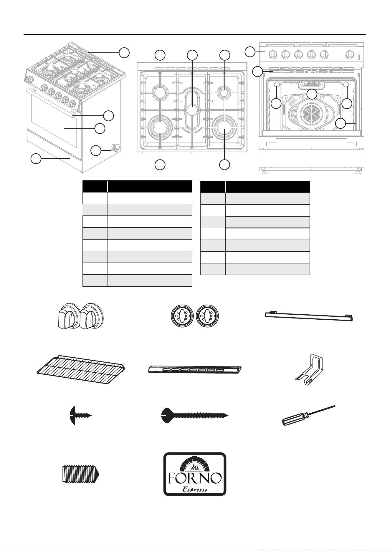
9
Names of Parts and Accessories
Numbers Parts
1 Left, Rear Burner 6000 BTU
2 Left, Front Burner 12000 BTU
3 Center Burner 6000 BTU
4 Right, Rear Burner 3500 BTU
5 Right, Front Burner 12000 BTU
6 Backsplash
7 Handle
8 Oven Door Window
Numbers Parts
9 Kick Plate
10 Anti-tip Bracket
11 Control Panel
12 Oven Vent
13 Oven Light
14 Convection Fan
15 Door Gasket
12x Forno Knobs
(Stainless Steel 6x & *Antique Brass 6x)
12x Forno Bezel
(Stainless Steel 6x & *Antique Brass 6x)
2x Forno Door Handle
(Stainless Steel & *Antique Brass)
2x Racks 1x Backsplash 1x Anti-Tip Bracket
5x Screws (M4*8)
(For blacksplash Installation)
2x Screws (M5*45)
(For Anti-tip bracket)
1x Hexagon wrench
2x Screws for the handle 1x Logo
1
5
4
2
6
7
8
9
10
11
12
15
13
13
3
14
*NOTE: Antique Brass hardware is only provided with the black and white color variant, the stainless steel only has the
stainless steel included
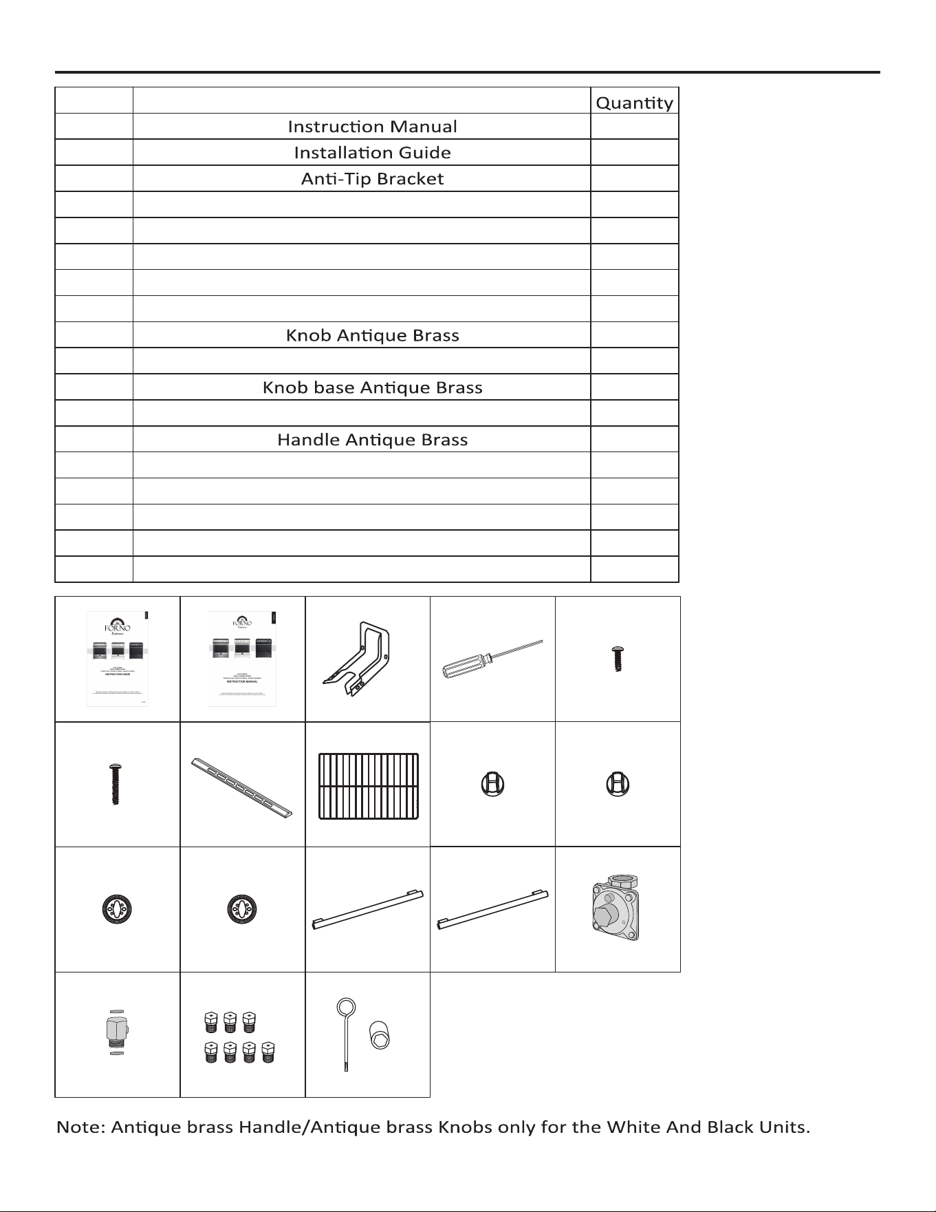
S/N Name
Backplash
Knob Stainless Steel
Knob base Stainless Steel
Screw (M4*8)
Screw (M5*45)
Oven Rack
Screwdriver
9
10
13
12
11
1
1
1
1
1
6
6
6
2
6
1
2
5
8
7
6
5
4
2
3
1
Handle Stainless Steel
Gas Pressure Regulator
Gas Pipe Adapter With Washers
Lp Gas Conversion Kit
Flame Adjustment Accessory
14
15
16
17
18
1
1
1
1
7
2
6 7 8
3 4
1
5
10
11
16
9
13
14 15
12
17 18
Packing List
10
Installations
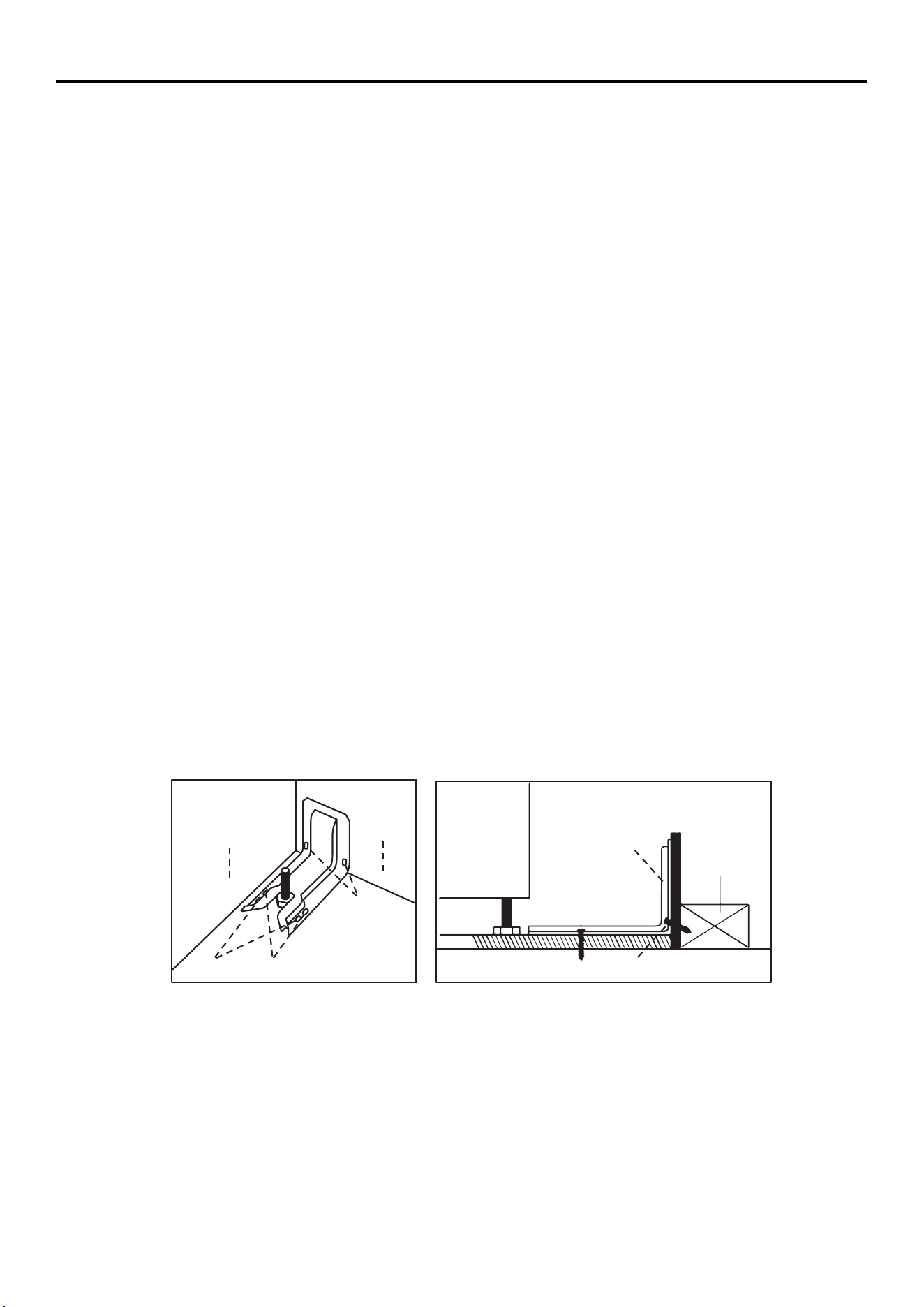
THE ANTI-TIP BRACKET
NOTE: An anti-tip bracket kit is provided with the range.
WARNING: Tip Over Hazard
• A child or adult can tip the range and be killed.
• Connect anti-tip bracket to rear range foot.
• Reconnect the anti-tip bracket if the range is moved.
• Failure to follow these instructions can result in death or serious burns to children and adults.
IMPORTANT: DO NOT completely remove the rear leveling leg. The anti-tip bracket uses either the right-hand or left
hand, rear leveling leg to secure the range to the oor.
1: Locate the bracket
Determine the nal location of the range before attempting to install the bracket.
A. Place the bracket on the oor with the back edge against the rear wall. If the range does not reach the rear wall,
align the back edge of the bracket with the rear panel of the range in its nal location.
NOTE: If bracket does not touch the rear wall, you MUST screw bracket to FLOOR .
B. Position the side of the bracket against either the left or right cabinet. If there is no adjacent cabinet, align the edge
of the bracket with the side panel of the range in its nal location. If the countertop overhangs the cabinet, oset
the bracket from the cabinet by the amount of overhang.
C. Mark the location for the pair of holes to be used (see illustration below).
NOTE: For FLOOR installation use either Loc A or B. For REAR WALL installation use Loc C.
2: Secure the bracket
The bracket must be screwed to either the FLOOR or REAR WALL.
FLOOR Installation:
• Wood oor: Use the screws provided to secure the bracket using the pair of marked holes (either Loc A or B).
• Concrete oor: Using a concrete bit, drill a 5/32” pilot hole 2” deep into the concrete at the center of each of the
marked holes (either Loc A or B). Use the screws provided to secure the bracket into the oor.
REAR WALL Installation:
Use the 2 screws provided to secure the bracket using the pair of marked holes at Loc C. The screws MUST enter a
Adjacent cabinet
or final location of
range side panel
Attachment to floor or rear wall
Bracket
Wall sill plate
Loc
C
Loc
A
Loc
B
Two screws must
enter floor or wall
at Loc A,B, or C.
Rear Wall
The screw must
enter to wood or
concrete
The screw must enter to wood
wood sill plate. If the wall contains any metal studs or similar materials, then the oor must be used.
3: Check The Bracket
After installing the bracket, slide the range into its nal location. The rear leveling leg must be fully inserted into the
ANTI-TIP bracket as shown in Step 1. To check if the bracket is installed and engaged properly, look underneath the
range to see that the rear leveling leg is engaged in the bracket. On some models, the storage drawer or kick panel
can be removed for easier inspection. If visual inspection is not possible, slide the range forward, conrm the anti-
tip bracket is securely attached to the oor or wall, and slide the range back so the leveling leg is under the anti-tip
bracket. If the range is pulled from the wall for any reason, always repeat this procedure to verify the range is properly
secured by the anti-tip bracket.
NOTE: The anti-tip bracket must be PROPERLY INSTALLED, and the rear leveling leg must be FULLY ENGAGED
into the bracket to prevent the range from tipping. NEVER remove the leveling legs. This will prevent the range from
being secured to the ANTI-TIP bracket properly.
11
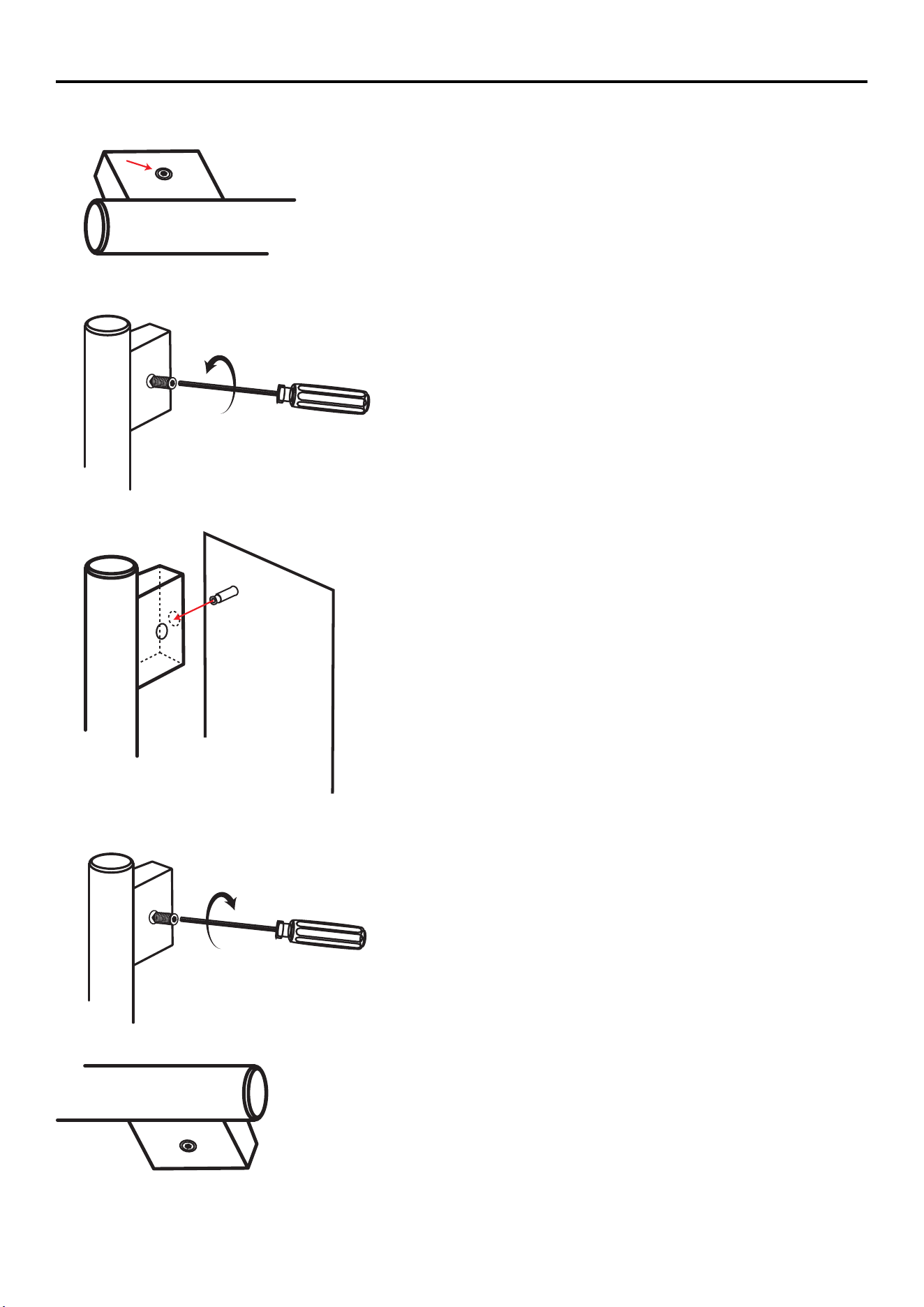
INSTALLING THE HANDLE
1. Locate the screw on the handle
2. Remove the screw with the provided hexagon wrench. (Repeat again on the other sides)
3. Fix the handle to the pin.
4. Then put back the screw and righten it with the hexagon wrench.(Repeat again on the other sides)
5. When you assemble the handles, make sure the screw is facing down to the oor.
Installations (continued)
12
Control Panel
OFF
˚F
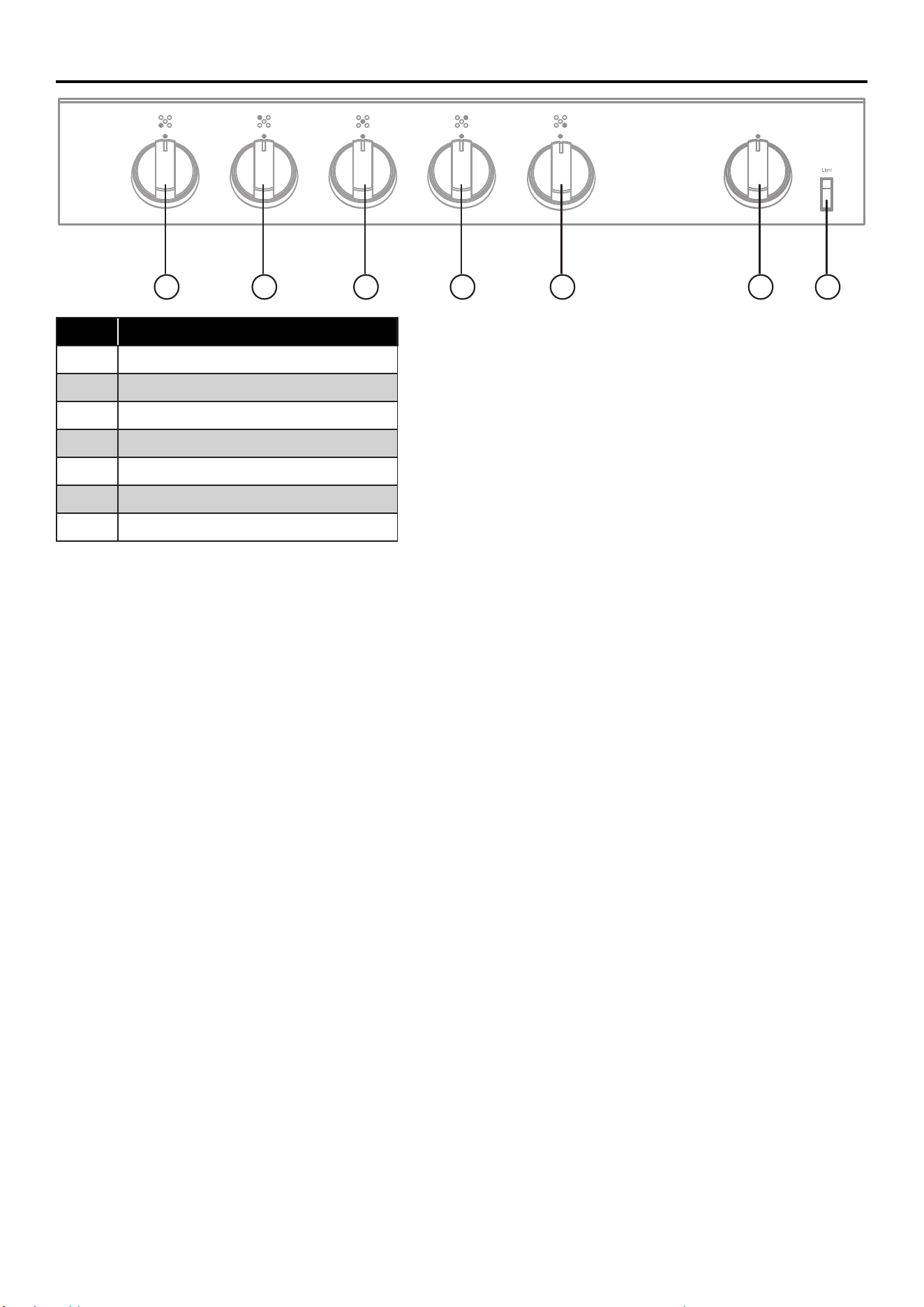
Numbers Parts
A
Front, left burner
B
Rear, left burner
C Center burner
D Rear, right burner
E Front right burner
F Oven Knob
G Light
A B C D E F G
Read the instructions before installing or using this appliance.
1. This appliance shall be installed in accordance with the regulations in force and only used in a well-ventilated
space.
2. The use of a gas-cooking appliance results in the production of heat and moisture in the room in which it is
installed. Ensure that the kitchen is well ventilated: keep natural ventilation holes open or install a mechanical
ventilation device (mechanical extractor hood).
3. Prolonged intensive use of the appliance may call for additional ventilation, for example opening of a window, or
more eective ventilation, for example increasing the level of mechanical ventilation where present.
IGNITION AND OPERATION OF THE BURNERS
To ignite a burner, push down on the burner knob and rotate it counterclockwise until the knob indicator is aligned with
the ignite icon. Release the knob and adjust the ame intensity by further rotating the knob counterclockwise from
MAX (maximum) to MIN (minimum).
NOTE: For models with a ame failure safety device - Once the ame is lit, hold the knob depressed for about 3-4
seconds until the device keeps the burner automatically lit. If the burner fails to ignite, wait one minute for the gas to
dissipate before attempting to reignite. To turn o the burner, rotate the knob clockwise until the indicator on the knob
is aligned with OFF.
POWER FAILURE
In case of prolonged power failure, the surface burners can be lit manually. Hold a lit match near a burner and turn
knob counterclockwise until the indicator is aligned with MAX. After the burner is lit, turn knob to desired setting.
In the case of unintentional ame extinguishing, the safety valve intervenes by shutting o the gas to the burners.
The electric igniter must not be actuated for longer than 15 seconds. Should the burner not light, or should the burner
be unintentionally turned o, immediately close the burner, and wait at least 1 minute before repeating. Once ignited,
adjust the ame as desired.
For lower gas consumption and a better result, use saucepans with a diameter matching the diameter of the burner, to
avoid the ame coming up around the sides of the saucepan. See the Container Table. Use only at bottomed pans.
As soon as liquid starts to boil, turn the ame down to a level sucient to maintain boiling.
Surface Burner Controls:
The ve cooktop burners, push and turn to the ignite position
and hold for several seconds till burners ignite successfully.
Oven Controls:
• Oven has two functions. Convection Bake and Broil.
• Convection Bake: Turn the knob to left to ignite the bottom
burner and convection fan will begin to activate.
Broil: Turn the knob to right to ignite the upper burner.
Light
Press the rocker switch to turn on and o light.
13
Operating Instruction
COOKWARE
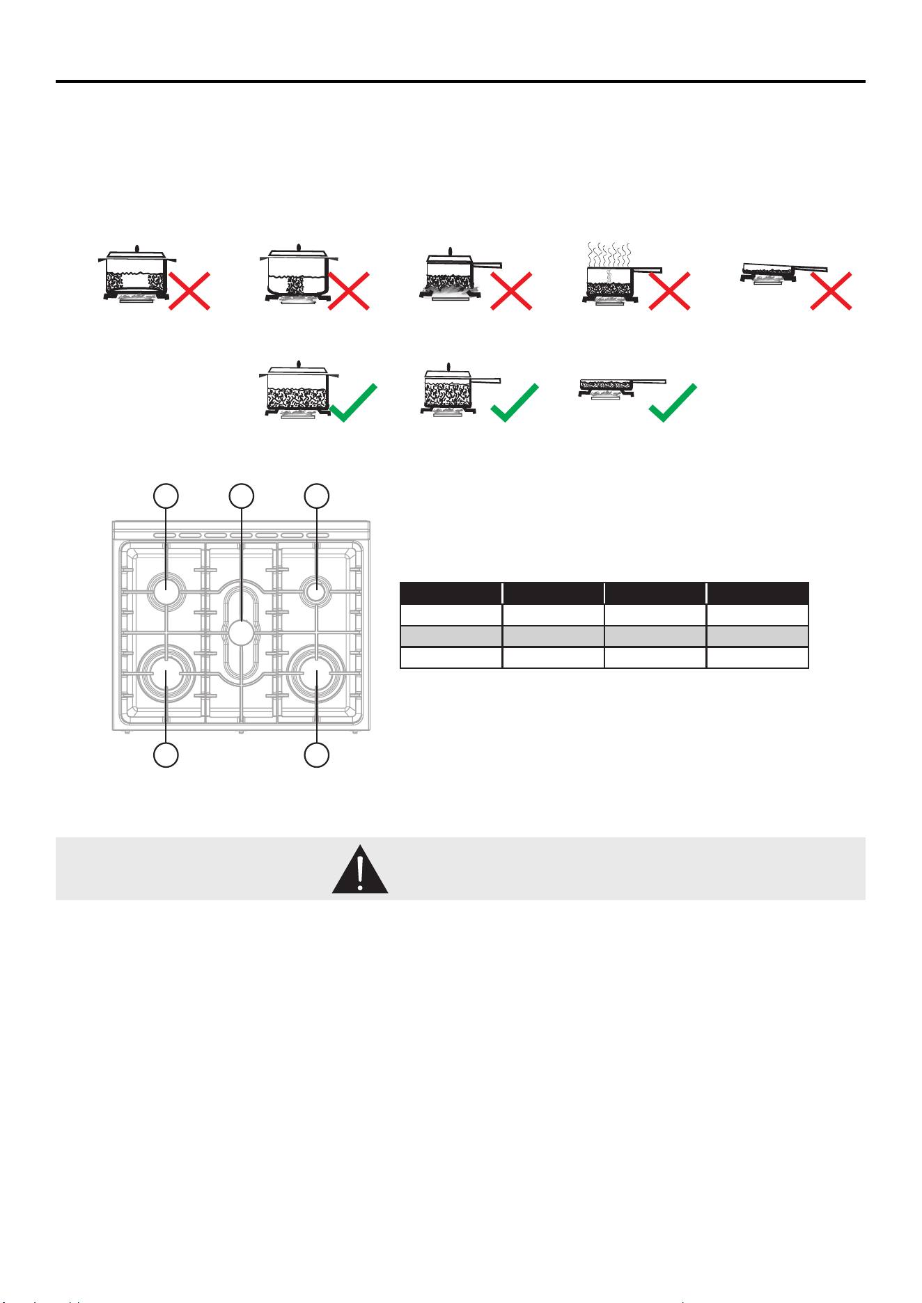
• Match pan diameter to ame size. The ame should be the same size as the bottom of the pan or smaller. Do not use small pans with high
ame settings as the ames can lick up the sides of the pan. Oversized pans that span two burners are placed front to rear, not side to side.
• Use balanced pans. Pans must sit level on the cooktop grate without rocking. Center the pan over the burner.
• Use a lid that ts properly. A well-tting lid helps shorten the cooking time. Flat, heavy bottom pans provide even heat and stability.
Burner # Burner type Min Saucepan Max Saucepan
4 Auxiliary 3.5” (9.0 cm) 6.3” (16 cm)
3 & 4 Semi-rapid 5.1” (13 cm) 7.1” (18 cm)
2 & 3 Rapid 5.9” (15 cm) 10.2” (26 cm)
1
5
4
2
3
Concave (Hollow) Convex (Rounded) Flame too large for
pan size
Use lids that Fit
properly
Unbalanced Pan
Balanced Pan
NEVER cover any slots, holes or passages in the oven bottom or cover an entire rack with materials such as
aluminum foil. Doing so blocks airow through the oven and may cause carbon monoxide poisoning. Aluminum foil
linings may also trap heat, causing a re hazard.
Reset all controls to the OFF position after using a programmable timing operation. No attempt should be made to
operate the appliance during power failure.
An air curtain or other overhead range hood, which operates by blowing a downward airow onto a range shall not
be used in conjunction with a gas range.
WARNING
14
Operating Instruction
OVEN CONTROLS
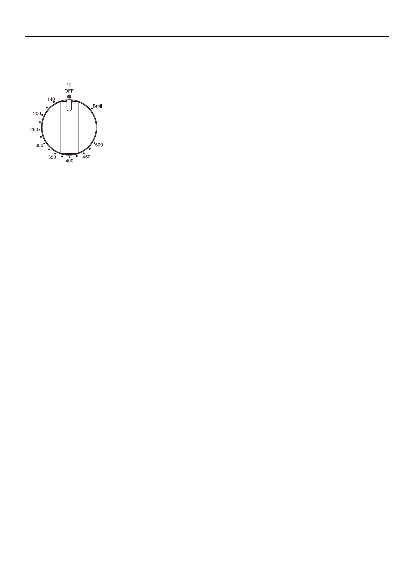
The Thermostat knob and Cooking-mode knobs are used together to select oven Modes
THERMOSTAT KNOB
Push in on the Thermostat knob, and then turn the knob to desired temperature
or broil, and wait for around 20 seconds till the burner ignites successfully.
Conv Bake
THERMOSTAT RANGE: 140°F (60°C) TO MAX 500°F (260°C)
The Conv Bake mode uses heat from the lower burner and convection fan assisted to cook food. When using this mode to prepare baked goods
such as cakes, cookies and pastries, always preheat the oven rst and place food centrally near the middle racks.
Broil
THERMOSTAT RANGE: Broil
The Broil mode uses intense heat from the upper element to sear foods. Ideal for toasting, melting cheese, browning and searing surface. Food
should be placed near the upper racks, and should not be cooked for too long on each side of the food. It is not necessary to preheat when using
this mode.
TIPS AND TECHNIQUES
Follow the recipe or convenience food directions for baking temperature, time and rack position. Baking time will vary
with the temperature of ingredients and the size, shape and nish of the baking utensil.
General Guidelines
• For best results, bake food on a single rack with at least 1” - 1½” (2.5 - 3 cm) space between utensils and oven walls.
• Use one rack when selecting the bake mode.
• Check for doneness at the minimum time.
• Use metal bake ware (with or without a non-stick nish), heatproof glass, glass-ceramic, pottery or other utensils
suitable for the oven.
• When using heatproof glass, reduce temperature by 25°F (15°C) from recommended temperature.
• Use baking sheets with or without sides or jelly roll pans.
• Dark metal pans or nonstick coatings will cook faster with more browning.
Insulated bake ware will slightly lengthen the cooking time for most foods.
• Do not use aluminum foil or disposable aluminum trays to line any part of the oven. Foil is an excellent heat insulator
and heat will be trapped beneath it. This will alter the cooking performance and can damage the nish of the oven.
• Avoid using the opened door as a shelf to place pans.
• See Troubleshooting for tips to Solving Baking and Roasting Problems.
15
Operating Instruction (continued)
Care and Maintenance
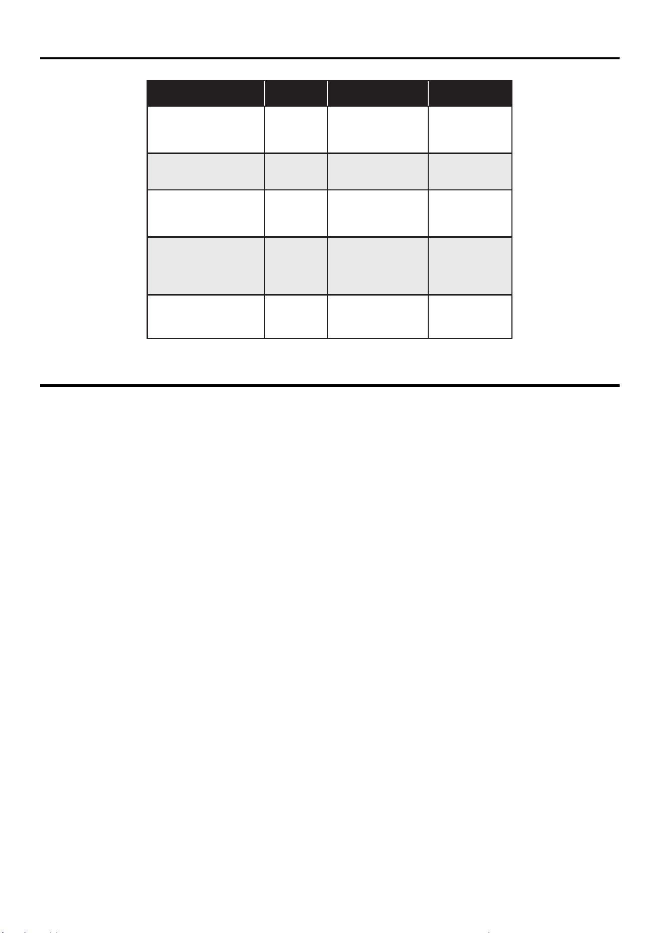
BAKE CHART
Food Item Rack Position
Temp. °F (°C)
(Preheated Oven)
Time (Min)
Cake
Cupcakes
Bundt Cake
Angel Food
2
1
1
350 (175)
350 (175)
350 (175)
19-22
40-45
35-39
Pie
2 crust, fresh, 9”
2 crust, frozen fruit, 9”
2
2
375-400 (190-205)
375 (190)
45-50
68-78
Cookies
Sugar
Chocolate Chip
Brownies
2
2
2
350-375 (175-190)
350-375 (175-190)
350 (175)
8-10
8-13
29-36
Breads
Yeast bread loaf, 9x5
Yeast rolls
Biscuits
Muns
2
2
2
2
375 (190)
375-400 (190-205)
375-400 (190-205)
425 (220)
18-22
12-15
7-9
15-19
Pizza
Frozen
Fresh
2
2
400-450 (205-235)
475 (246)
23-26
15-18
CLEANING
IMPORTANT: Before cleaning, make sure all controls are o and the oven and cooktop are cool. Always follow label
instructions on cleaning products. Soap, water and a soft cloth or sponge are suggested rst unless otherwise noted.
Do not use abrasive cleaning products.
EXTERIOR PORCELAIN ENAMEL SURFACES
• Food spills containing acids, such as vinegar and tomato, should be cleaned as soon as the entire appliance is cool.
These spills may aect the nish.
Cleaning Method:
• Glass cleaner, mild liquid cleaner or nonabrasive scrubbing pad: Gently clean around the model and serial number
plate because scrubbing may remove numbers.
EXTERIOR STAINLESS STEEL
NOTE: Do not use soap-lled scouring pads, abrasive cleaners, Cooktop Polishing Cream, steel-wool pads, gritty
washcloths or some paper towels. Damage may occur, even with one-time or limited use.
• Rub in direction of grain to avoid damaging.
Cleaning Methods:
• Liquid detergent or all-purpose cleaner: Rinse well with clean water and dry with soft, lint-free cloth.
• Stainless Steel Cleaner and Polish. Vinegar for hard water spots.
OVEN DOOR EXTERIOR
Cleaning Method:
• Glass cleaner and paper towels or nonabrasive plastic scrubbing pad: Apply glass cleaner to soft cloth or sponge,
not directly on panel.
PORCELAIN-COATED GRATES AND CAPS
• Clean as soon as cooktop, grates and caps are cool.
• Food spills containing acids, such as vinegar and tomato, should be cleaned as soon as the cooktop grates and
caps are cool. These spills may aect the nish.
• To avoid chipping, do not bang grates and caps against each other or hard surfaces such as cast iron cookware.

16
• Do not reassemble caps on burners while wet.
Cleaning Method:
• Nonabrasive plastic scrubbing pad and mildly abrasive cleanser.
BURNER SPREADER
• Wash the burner spreader frequently with boiling water and detergent to remove any deposits which could block
the ame outlet.
• Before reinstalling, dry the burner spreader thoroughly so the burner will ignite properly.
COOKTOP CONTROL KNOBS
• Pull knobs straight away from control panel to remove.
• When replacing knobs, make sure knobs are in the O position.
Cleaning Method:
• Soap and water or dishwasher.
NOTE: Do not use steel wool, abrasive cleansers or oven cleaner. Do not soak knobs.
CONTROL PANEL
Cleaning Method:
• Glass cleaner and soft cloth or sponge: Apply glass cleaner to soft cloth or sponge, not directly on panel.
NOTE: Do not use abrasive cleaners, steel-wool pads, gritty washcloths or some paper towels. Damage may
occur.
OVEN CAVITY
• Food spills should be cleaned when oven cools. At high temperatures, foods react with porcelain, so staining,
etching, pitting or faint white spots can result.
Cleaning Method:
• Mild detergent and warm water.
NOTE: Do not use oven cleaners.
OVEN RACKS AND ROASTING RACKS
Cleaning Method:
• Steel-wool pad
2-PIECE BROILER PAN
Cleaning Method:
• Mildly abrasive cleanser: Scrub with wet scouring pad.
• Solution of ½ cup (125 mL) ammonia to 1 gal. (3.75 L) water: Soak for 20 minutes, and then scrub with scouring
or steel-wool pad.
• Oven cleaner: Follow product label instructions. Porcelain enamel only, not chrome Dishwasher.
Care and Maintenance (continued)
17
Troubleshooting
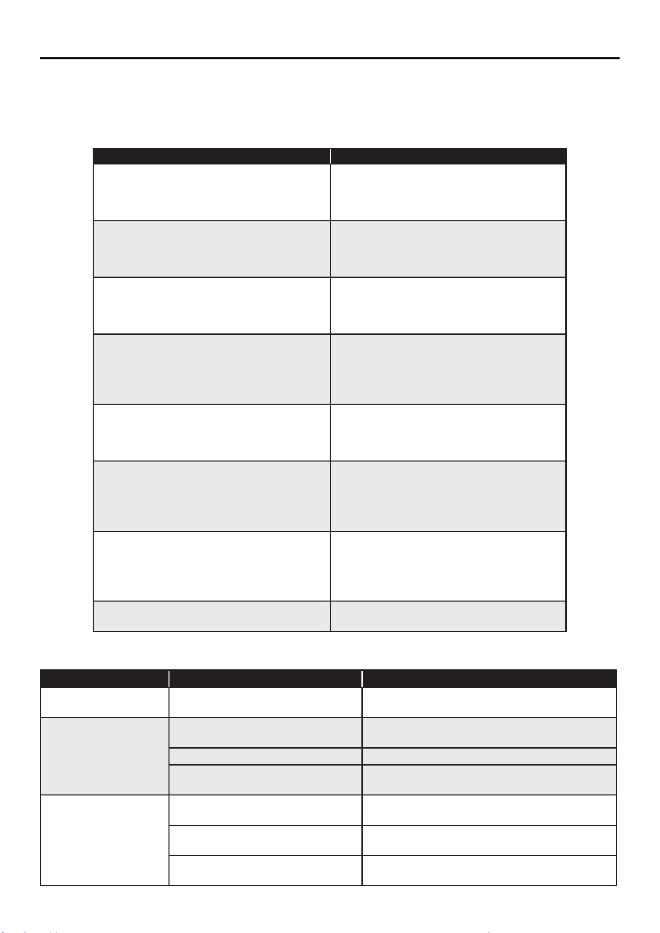
First try the solutions suggested here to possibly avoid the cost of a service call.
BAKING AND ROASTING PROBLEMS
Before contacting Forno customer service, please check the chart below for cases that may apply to you. It can be
simple misuse of material, shapes, and sizes of bakeware that causes poor results.
Cooktop Probkems
Baking Issues Causes
Food browns unevenly • Oven not preheated
• Aluminum foil on oven rack or oven bottom
• Baking utensil too large for recipe
• Pans touching each other or oven walls
Food too brown on bottom • Oven not preheated
• Using glass, dull or darkened metal pans
• Incorrect rack position
• Pans touching each other or oven walls
Food is dry or has shrunk excessively • Oven temperature too high
• Baking time too long
• Oven door opened frequently
• Pan size too large
Food is baking or roasting too slowly • Oven temperature too low
• Oven not preheated
• Oven door opened frequently
• Tightly sealed with aluminum foil
• Pan size too small
Pie crusts do not brown on bottom or crust is
soggy
• Baking time not long enough
• Using shiny steel pans
• Incorrect rack position
• Oven temperature is too low
Cakes pale, at and may not be done inside • Oven temperature too low
• Incorrect baking time
• Cake tested too soon
• Oven door opened too often
• Pan size may be too large
Cakes high in middle with crack on top • Oven temperature too high
• Baking time too long
• Pans touching each other or oven walls
• Incorrect rack position
• Pan size too small
Piecrust edges too brown • Oven temperature too high
• Edges of crust too thin
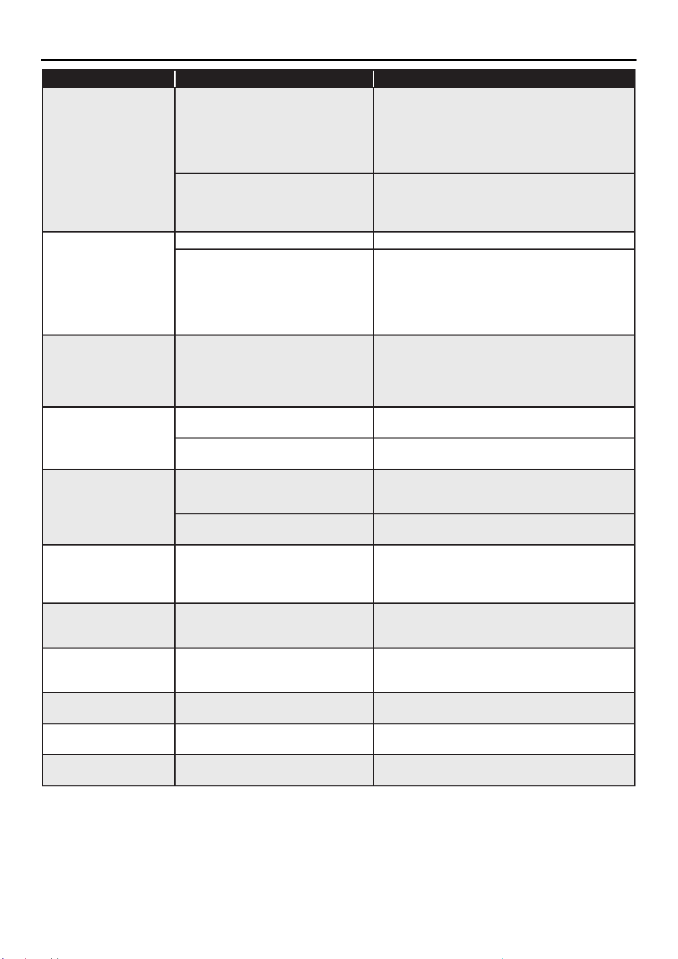
Problem Possible Causes Solutions
Burner will not ignite There is no power to the range.
Check that range is properly connected to 3- or
4-wire, 240V power supply.
Burner will not operate
First time use. Air still in the gas line.
Turn on any one of the surface burner knobs to
release air from the gas lines.
Control knob is not set correctly. Push in knob before turning to a setting.
The burner port is clogged.
Clean burner port opening using a sti, nylon
toothbrush or a straightened paper clip.
Burner Flames are
uneven, yellow and/ or
noisy
Burner port(s) are clogged.
Clean burner port opening using a sti, nylon
toothbrush or a straightened paper clip.
Burner caps are not positioned
properly.
Place burner caps so that the alignment pins are
properly aligned with the slots.
Propane gas is being used.
The range should be converted to LP gas by a
qualied technician.
18
Problem Possible Causes Solutions
Burner ame is too high
or too low
Cooktop gas supply is not correct.
Ensure the range is set for the correct gas type.
It is factory set for natural gas. If connecting to
LP gas, the burners should be converted to LP
gas with the orice kit supplied and the pressure
regulator converted to the LP gas setting by a
qualied technician.
The gas pressure is not correct.
Make sure the pressure regulator is installed
correctly and the gas line pressure is correct. See
Installation
Instructions.
Burner makes popping
noises
The burner is wet. Allow the burner to dry before using.
The burner cap or gas spreader is
not positioned correctly.
Use cookware with a bottom surface
approximately the same size as the cooking area
and burner. Cookware should not extend more
than 1” (2.5 cm) outside the cooking area. Adjust
the ame so that it does not come up around the
cookware.
Excessive heat around
cookware on cooktop
The cookware is not the proper size
for the burner.
Use cookware with a bottom surface
approximately the same size as the cooking area
and burner. Cookware should not extend more
than 1” (2.5 cm) outside the cooking area. Adjust
the ame so that it does not
Cooking results are not
what expected
Using incorrect cookware. See the “Cookware” section.
The control knob is not set to the
proper heat level.
See the “Cookware” section.
Oven is not heating
No power to the range.
Check the circuit breaker or fuse box to your
house. Make sure there is proper electrical power
to the oven.
Oven control not turned on.
Make sure the oven temperature has been
selected.
Oven is not cooking
evenly
Not using the correct bake ware or
oven rack position.
Refer to cook charts for recommended rack
position. Always reduce recipe temperature by
25 °F (15 °C) when baking with Convention Bake
mode.
Oven display stays O Power interruption.
Turn o power at the main power supply (fuse or
breaker box). Turn breaker back on. If condition
persists, call for service.
Cooling fan continues to
run after oven is turned
o
The electronic components have not
yet cooled suciently.
The fan will turn o automatically when the
electronic components have cooled suciently.
Oven light is not
working properly
Light bulb loose or burned-out.
Reinsert or replace the light bulb. Touching the
bulb with ngers may cause the bulb to burn out.
Oven light stays on Door is not closing completely
Check for obstruction in oven door. Check to see
if hinge is bent or door switch broken.
Cannot remove lens
cover
Soil build-up around the lens cover.
Wipe lens cover area with a clean, dry towel prior
to attempting to remove the lens cover.
Troubleshooting (continued)

19
Problem Possible Causes Solutions
Clock and timer are not
working properly
No power to the range.
Check the circuit breaker or fuse box to your
house. Make sure there is proper electrical power
to the oven. Check the circuit breaker or fuse
box to your house. Make sure there is proper
electrical power to the oven.
Excessive
Moisture
When using bake mode, preheat the oven rst.
Convection Bake and Convection Roast will
eliminate any moisture in the oven.
Porcelain
Chips
Porcelain interior is chipped by oven
racks
When removing and replacing oven racks, always
tilt racks upward and do not force them to avoid
chipping the porcelain.
Troubleshooting (continued)

20
What this limited warranty covers:
The Warranty coverage provided by Forno Appliances in
this statement applies exclusively to the original Forno
appliance (“Product”) sold to the consumer (“Purchaser”) by
an authorized Forno dealer/distributor/retailer, purchased
and installed in the United States or Canada, and which has
always remained within the original country of purchase (the
United States or Canada). Warranty coverage is activated on
the date of the Product’s original retail purchase and has a
duration of two (2) years.
Warranty coverage is non-transferable. In the event
of replacement of parts or of the entire product, the
replacement Product (or parts) shall assume the remaining
original Warranty activated with the original retail purchase
document. This Warranty shall not be extended with respect
to such replacement. Forno Appliances will repair or replace
any component/part which fails or proves defective due to
materials and/or workmanship within 2 years of the date of
the original retail purchase and under conditions of ordinary
residential, non-commercial use. Repair or replacement
will be free of charge, including labor at standard rates and
shipping expenses. Purchaser is responsible for making the
Product reasonably accessible for service. Repair service
must be performed by a Forno Authorized Service company
during normal working hours.
Important
Retain proof of original purchase to establish warranty
period. Forno’s liability on any claim of any kind, with respect
to the goods and/or services provided, shall in no event
exceed the value of the goods or service or part there of
which has given rise to the claim.
30-Day Cosmetic Warranty
The Purchaser must inspect the product at the time of
delivery. Forno warrants that the Product is free from
manufacturing defects in materials and workmanship for
a period of thirty (30) days from date of the original retail
purchase of the Product.
This coverage includes:
• Paint blemishes
• Chips
• Macroscopic finish defects
Cosmetic warranty does NOT cover:
• Issues resulting from incorrect transport, handling and/
or installation (e.g.: dents, broken, warped or deformed
structures or components, cracked or otherwise
damaged glass components);
• Slight color variations on painted/enameled components;
• Differences caused by natural or artificial lighting,
location or other analogous factors; > stains/corrosion/
discoloration caused by external substances and/
or environmental factors; > labor costs, display, floor,
B-stock, out- of-box,“as is” appliances and demo units.
How to receive service
To receive warranty services, the Purchaser must contact the
Forno Support department in order to determine the problem
and the required service procedures. Troubleshooting with
a customer service representative will be necessary before
moving forward with the service. Model number, serial
number and date of original retail purchase will be requested.
Warranty Exclusions: What Is Not Covered.
• Use of the Product in any non-residential, commercial
application.
• Use of the Product for anything other than its intended
purpose.
• Repair services provided by anyone other than a Forno
Authorized Service agency.
• Damages or repair services to correct services provided
by unauthorized parties or the use of unauthorized parts.
• Installation not in accordance with local/state/city/county
fire codes, electrical codes, gas codes, plumbing codes,
building codes, laws or regulations.
• Defects or damage due to improper storage of the
Product.
• Defects, damage or missing parts on products sold out
of the original factory packaging or from displays. >
Service calls or repairs to correct an incorrect installation
of the Product and/or related accessories.
• Replacement of parts/service calls to connect, convert
or otherwise repair the electrical wiring and/or gas line in
order to properly use the product.
• Replacement of parts/service calls to provide
instructions and information on the use of the Product.
• Replacement of parts/service calls to correct issues
arising from the product being used in a manner other
than what is normal and customary for residential use.
• Replacement of parts/service calls due to wear and tear
of components such as seals, knobs, pan supports,
shelving, cutlery baskets, buttons, touch displays,
scratched or broken ceramic-glass tops.
• Replacement of parts/service calls for lack of/improper
maintenance, including but not limited to: build up of
residues, stains, scratches, discoloration, corrosion.
• Defects and damages arising from accidents, alteration,
misuse, abuse or improper installation.
• Defects and damages arising from Product transport,
logistics and handling. Inspection of the product must
be made at time of delivery. Following receipt and
inspection, the selling dealer/delivery company must be
notified of any issues arising from handling, transport
and logistics.
• Defects and damages arising from external forces
beyond the control of Forno Appliances, including but
not limited to wind, rain, sand, fires, floods, mudslides,
freezing temperatures, excessive moisture or extended
exposure to humidity, power surges,
• Lightning, structural failures surrounding the appliance
and other acts of God.
• Products whose serial number has been altered/
damaged/tampered with. In no case shall Forno be held
liable or responsible for damage to surrounding property,
including furniture, cabinetry, flooring, panels, and other
structures surrounding the Product. Forno is neither
liable nor responsible for the Product if it is located
in a remote area or an area where certified trained
technicians are not reasonably available. Purchaser
must bear any transportation and delivery costs of the
Product to the nearest Authorized Service Center or
the additional travel expenses of a certified trained
technician
Warranty

21
THERE ARE NO EXPRESS WARRANTIES OTHER THAN THOSE LISTED AND DESCRIBED ABOVE, AND NO WARRANTIES, EITHER EXPRESS OR
IMPLIED, INCLUDING, BUT NOT LIMITED TO, ANY IMPLIED WARRANTIES OF MERCHANTABILITY OR FITNESS FOR A PARTICULAR PURPOSE THAT
SHALL APPLY AFTER THE EXPRESS WARRANTY PERIODS STATED ABOVE, AND NO OTHER EXPRESS WARRANTY OR GUARANTEE GIVEN BY
ANY PERSON, FIRM OR CORPORATION WITH RESPECT TO THIS PRODUCT SHALL BE BINDING ON FORNO. FORNO SHALL NOT BE LIABLE FOR
LOSS OF REVENUE OR PROFITS, FAILURE TO REALIZE SAVINGS OR OTHER BENEFITS, TIME AWAY FROM WORK, MEALS, LOSS OF FOOD OR
BEVERAGES, TRAVELING OR HOTEL EXPENSES, EXPENSES TO RENT OR PURCHASE APPLIANCES, REMODELING/CONSTRUCTION EXPENSES
IN EXCESS OF DIRECT DAMAGES WHICH ARE UNDENIABLY CAUSED EXCLUSIVELY BY FORNO OR ANY OTHER SPECIAL, INCIDENTAL OR
CONSEQUENTIAL DAMAGES CAUSED BY THE USE, MISUSE OR INABILITY TO USE THIS PRODUCT, REGARDLESS OF THE LEGAL THEORY ON
WHICH THE CLAIM IS BASED, AND EVEN IF FORNO HAS BEEN ADVISED OF THE POSSIBILITY OF SUCH DAMAGES. NOR SHALL RECOVERY OF
ANY KIND AGAINST FORNO BE GREATER IN AMOUNT THAN THE PURCHASE PRICE OF THE PRODUCT SOLD BY FORNO AND CAUSING THE
ALLEGED DAMAGE. WITHOUT PREJUDICE TO THE FOREGOING, PURCHASER ASSUMES ALL RISK AND LIABILITY FOR LOSS, DAMAGE OR INJURY
TO PURCHASER AND PURCHASER’S PROPERTY AND TO OTHERS AND THEIR PROPERTY ARISING FROM THE USE, MISUSE, OR INABILITY TO
USE THIS PRODUCT SOLD BY FORNO THAT IS NOT A DIRECT RESULT OF NEGLIGENCE ON THE PART OF FORNO THIS LIMITED WARRANTY SHALL
NOT EXTEND TO ANYONE OTHER THAN THE ORIGINAL PURCHASER OF THIS PRODUCT, IS NON-TRANSFERABLE, AND STATES YOUR EXCLUSIVE
REMEDY.
Correct Disposal of this product:
This marking indicates that this appliance should not be disposed with
other household wastes. To prevent possible harm to the environment or
human health from uncontrolled waste disposal, recycle it responsibly to
promote the sustainable reuse of material resources.
Warranty (continued)