Installation/Operation/Maintenance
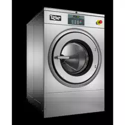
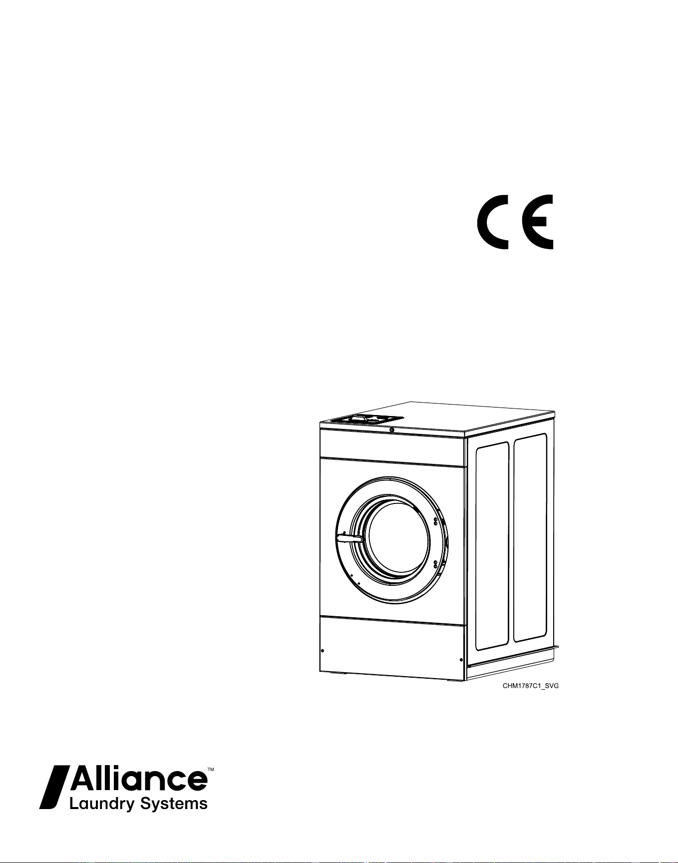
Washer-Extractors
Cabinet Hardmount
Design 4 Models
Refer to Page 8 for Model Identification
Original Instructions
Keep These Instructions for Future Reference.
CAUTION: Read the instructions before using the machine.
(If this machine changes ownership, this manual must accompany machine.)
www.alliancelaundry.com
Part No. F8619501ENR4
August 2018
Downloaded from www.ManualsFile.com manuals search engine


Table of Contents
Models with Wireless Board Installed.....................................................5
Safety Information..................................................................................6
Explanation of Safety Messages....................................................................... 6
Important Safety Instructions........................................................................... 6
Safety Decals................................................................................................. 7
Operator Safety.............................................................................................. 7
Introduction........................................................................................... 9
Model Identification........................................................................................9
Delivery Inspection.......................................................................................20
Serial Plate Location..................................................................................... 21
Replacement Parts ........................................................................................21
Customer Service..........................................................................................21
Manufacturing Date...................................................................................... 21
Specifications and Dimensions ..............................................................22
Machine Dimensions.....................................................................................25
Mounting Bolt Hole Locations – 20 and 30 Models..........................................35
Mounting Bolt Hole Locations - 40 and 60 Models.......................................... 37
Mounting Bolt Hole Locations – 80 and 100 Models ....................................... 39
Installation........................................................................................... 41
Foundation Options.......................................................................................41
Machine Installation on Existing Floor........................................................ 41
Elevated Pad Installation on Existing Floor..................................................41
Elevated Base Frame Installation on Existing Floor...................................... 41
New Foundation........................................................................................41
Isolated Pad Installation............................................................................. 41
Foundation and Pad Installation......................................................................42
Floor Layout and Pad Dimensions.................................................................. 43
Foundation Requirements.............................................................................. 52
Machine Mounting and Grouting....................................................................56
Drain Connection Requirements.....................................................................59
Water Connection Requirements.....................................................................62
Connect Inlet Hoses (20-40 Models)........................................................... 64
Connect Inlet Hoses with Y-Connectors (60-100 Models)..............................64
Plumbing Diagrams.......................................................................................66
Electrical Installation Requirements................................................................71
Input Power Conditioning..............................................................................72
Input Voltage Requirements........................................................................72
Circuit Breakers and Quick Disconnects......................................................... 72
©
Copyright 2018, Alliance Laundry Systems LLC
All rights reserved. No part of the contents of this book may be reproduced or transmitted in any form or by any means without the expressed
written consent of the publisher.
©
Copyright, Alliance Laundry Systems LLC -
DO NOT COPY or TRANSMIT
3 Part No. F8619501ENR4
Downloaded from www.ManualsFile.com manuals search engine

Connection Specifications..............................................................................72
Single-Phase Connections.......................................................................... 73
Three-Phase Connections........................................................................... 73
Grounding................................................................................................ 74
Phase Adder..............................................................................................74
Thermal Overload Protector....................................................................... 74
North American Approval..........................................................................75
CE Approval.............................................................................................82
Steam Requirements (Steam Heat Option Only)...............................................87
Chemical Injection Supply System................................................................. 88
External Supplies..........................................................................................91
Chemical Injection Using Internal 24VAC Control Transformer.....................91
Chemical Injection Using External AC Power Source................................... 92
External Supply Signals............................................................................. 93
Start Up................................................................................................95
Basket Rotation............................................................................................ 95
Operation............................................................................................. 96
Operating Instructions................................................................................... 96
OPL Control Instructions...............................................................................97
Models with F Control............................................................................... 97
SCA, SCD, SCG, SCH, SCJ, SCT, SCU, UCA, UCD, UCG, UCH, UCJ, UCT
and UCU Models with N Control ........................................................... 97
HCA, HCD, HCG, HCH, HCJ, HCT and HCU, UCA, UCD, UCG, UCH, UCJ,
UCT and UCU Models with Q Control ................................................... 97
Vend Control Instructions.............................................................................. 99
HCT Models with N and W Controls...........................................................99
SCA, SCE, SCG, SCJ and SCU Models with N and W Controls ................... 99
DCJ, SCH and SCT Models with N and W Controls................................... 100
HCA, HCD, HCE, HCH, HCJ and HCU Models with N and W Controls .....100
SCT Modles with Q Control..................................................................... 101
HCT Models with Q Control.....................................................................102
Adding Supplies..........................................................................................102
Emergency Stop Button (OPL Models Only)................................................. 103
Maintenance....................................................................................... 105
Daily..........................................................................................................105
Beginning of Day.................................................................................... 105
End of Day..............................................................................................105
Monthly..................................................................................................... 105
Yearly........................................................................................................ 106
Care of Stainless Steel................................................................................. 108
Disposal of Unit...................................................................................109
China Restriction of hazardous substances (RoHS)..............................110
©
Copyright, Alliance Laundry Systems LLC -
DO NOT COPY or TRANSMIT
4 Part No. F8619501ENR4
Downloaded from www.ManualsFile.com manuals search engine

Models with Wireless Board Installed
This device is granted for use in Mobile only configurations in
which the antennas used for this transmitter must be installed to
provide a separation distance of at least 20cm from all person and
not be co-located with any other transmitters except in accord-
ance with FCC and Industry Canada multi-transmitter product
procedures.
Models with Wireless Board Installed
©
Copyright, Alliance Laundry Systems LLC -
DO NOT COPY or TRANSMIT
5 Part No. F8619501ENR4
Downloaded from www.ManualsFile.com manuals search engine
Safety Information
Explanation of Safety Messages
Precautionary statements (“DANGER,” “WARNING,” and
“CAUTION”), followed by specific instructions, are found in this
manual and on machine decals. These precautions are intended
for the personal safety of the operator, user, servicer, and those
maintaining the machine.
DANGER
Indicates an imminently hazardous situation that, if
not avoided, will cause severe personal injury or
death.
WARNING
Indicates a hazardous situation that, if not avoided,
could cause severe personal injury or death.
CAUTION
Indicates a hazardous situation that, if not avoided,
may cause minor or moderate personal injury or
property damage.
Additional precautionary statements (“IMPORTANT” and
“NOTE”) are followed by specific instructions.
IMPORTANT: The word “IMPORTANT” is used to in-
form the reader of specific procedures where minor
machine damage will occur if the procedure is not fol-
lowed.
NOTE: The word “NOTE” is used to communicate in-
stallation, operation, maintenance or servicing informa-
tion that is important but not hazard related.
Important Safety Instructions
WARNING
To reduce the risk of fire, electric shock, serious in-
jury or death to persons when using your washer,
follow these basic precautions:
W023
• Read all instructions before using the washer.
• Install the washer according the INSTALLATION instruc-
tions. Refer to the EARTH/GROUND instructions in the IN-
STALLATION manual for the proper earth/ground connection
of the washer. All connections for water, drain, electrical
power and earth/ground must comply with local codes and be
made by licensed personnel when required. It is recommend-
ed that the machine be installed by qualified technicians.
• Do not install or store the washer where it will be exposed to
water and/or weather.
• To prevent fire and explosion, keep the area around machine
free from flammable and combustible products. Do not add
the following substances or textiles containing traces of the
following substances to the wash water: gasoline, kerosene,
waxes, cooking oils, vegetable oils, machine oils, dry-clean-
ing solvents, flammable chemicals, thinners, or other flamma-
ble or explosive substances. These substances give off vapors
that could ignite, explode or cause the fabric to catch fire by
itself.
• Under certain conditions, hydrogen gas may be produced in a
hot water system that has not been used for two weeks or
more. HYDROGEN GAS IS EXPLOSIVE. If the hot water
system has not been used for such a period, before using a
washing machine or combination washer-dryer, turn on all hot
water faucets and let the water flow from each for several mi-
nutes. This will release any accumulated hydrogen gas. The
gas is flammable, do not smoke or use an open flame during
this time.
• To reduce the risk of an electric shock or fire, DO NOT use an
extension cord or an adapter to connect the washer to the elec-
trical power source.
• Do not allow children to play on or in the washer. Close su-
pervision of children is necessary when the washer is used
near children. This appliance is not intended for use by young
children or infirm persons without supervision. Young chil-
dren should be supervised to ensure that they do not play with
the appliance. This is a safety rule for all appliances.
• DO NOT reach and/or climb into the tub or onto the washer,
ESPECIALLY if the wash drum is moving. This is an immi-
nently hazardous situation that, if not avoided, will cause se-
vere personal injury or death.
• Never operate the washer with any guards, panels and/or parts
removed or broken. DO NOT bypass any safety devices or
tamper with the controls.
• Use washer only for its intended purpose, washing textiles.
Never wash machine parts or automotive parts in the ma-
chine. This could result in serious damage to the basket or
tub.
• Use only low-sudsing, no-foaming types of commercial deter-
gent. Be aware that hazardous chemicals may be present.
Wear hand and eye protection when adding detergents and
chemicals. Always read and follow manufacturer’s instruc-
tions on packages of laundry and cleaning aids. Heed all
warnings or precautions. To reduce the risk of poisoning or
Safety Information
©
Copyright, Alliance Laundry Systems LLC -
DO NOT COPY or TRANSMIT
6 Part No. F8619501ENR4
Downloaded from www.ManualsFile.com manuals search engine
chemical burns, keep them out of the reach of children at all
times [preferably in a locked cabinet].
• Do not use fabric softeners or products to eliminate static un-
less recommended by the manufacturer of the fabric softener
or product.
• Always follow the fabric care instructions supplied by the tex-
tile manufacturer.
• Loading door MUST BE CLOSED any time the washer is to
fill, tumble or spin. DO NOT bypass the loading door switch
by permitting the washer to operate with the loading door
open. Do not attempt to open the door until the washer has
drained and all moving parts have stopped.
• Be aware that hot water is used to flush the supply dispenser.
Avoid opening the dispenser lid while the machine is running.
• Do not attach anything to the supply dispenser’s nozzles, if
applicable. The air gap must be maintained.
• Do not operate the machine without the water reuse plug or
water reuse system in place, if applicable.
• Be sure water connections have a shut-off valve and that fill
hose connections are tight. CLOSE the shut-off valves at the
end of each wash day.
• Keep washer in good condition. Bumping or dropping the
washer can damage safety features. If this occurs, have wash-
er checked by a qualified service person.
• DANGER: Before inspecting or servicing machine, power
supply must be turned OFF. The servicer needs to wait for at
least 5 minutes after turning the power OFF and needs to
check for residual voltage with a voltage meter. The inverter
capacitor or EMC filter remains charged with high voltage for
some time after powering OFF. This is an imminently hazard-
ous situation that, if not avoided, will cause severe personal
injury or death.
• Do not repair or replace any part of the washer, or attempt any
servicing unless specifically recommended in the user-mainte-
nance instructions or in published user-repair instructions that
the user understands and has the skills to carry out. ALWAYS
disconnect the washer from electrical, power and water sup-
plies before attempting any service.
• Disconnect the power by turning off the circuit breaker or by
unplugging the machine. Replace worn power cords.
• Before the washer is removed from service or discarded, re-
move the door to the washing compartment.
• Failure to install, maintain, and/or operate this washer accord-
ing to the manufacturer’s instructions may result in conditions
which can produce bodily injury and/or property damage.
NOTE: The WARNINGS and IMPORTANT SAFETY IN-
STRUCTIONS appearing in this manual are not meant
to cover all possible conditions and situations that may
occur. Common sense, caution and care must be exer-
cised when installing, maintaining, or operating the
washer.
Any problems or conditions not understood should be reported to
the dealer, distributor, service agent or the manufacturer.
WARNING
Machine installations must comply with minimum
specifications and requirements stated in the appli-
cable Installation Manual, any applicable municipal
building codes, water supply requirements, electrical
wiring regulations and any other relevant statutory
regulations. Due to varied requirements and applica-
ble local codes, this machine must be installed, ad-
justed, and serviced by qualified maintenance per-
sonnel familiar with applicable local codes and the
construction and operation of this type of machinery.
They must also be familiar with the potential hazards
involved. Failure to observe this warning may result
in personal injury, property damage, and/or equip-
ment damage, and will void the warranty.
W820
IMPORTANT: Ensure that the machine is installed on a
level floor of sufficient strength. Ensure that the recom-
mended clearances for inspection and maintenance are
provided. Never allow the inspection and maintenance
space to be blocked.
WARNING
Never touch internal or external steam pipes, con-
nections, or components. These surfaces can be ex-
tremely hot and will cause severe burns. The steam
must be turned off and the pipe, connections, and
components allowed to cool before the pipe can be
touched.
SW014
NOTE: All appliances are produced according the EMC-
directive (Electro-Magnetic-Compatibility). They can be
used in restricted surroundings only (comply minimally
with class A requirements). For safety reasons there
must be kept the necessary precaution distances with
sensitive electrical or electronic device(s). These ma-
chines are not intended for domestic use by private
consumers in the home environment.
Safety Decals
Safety decals appear at crucial locations on the machine. Failure
to maintain legible safety decals could result in injury to the oper-
ator or service technician.
Use manufacturer-authorized spare parts to avoid safety hazards.
Operator Safety
Safety Information
©
Copyright, Alliance Laundry Systems LLC -
DO NOT COPY or TRANSMIT
7 Part No. F8619501ENR4
Downloaded from www.ManualsFile.com manuals search engine
WARNING
NEVER insert hands or objects into basket until it
has completely stopped. Doing so could result in se-
rious injury.
SW012
Machines referred to by model in this manual are intended to be
used by the general public in applications such as:
• staff areas in shops, offices, kitchens and other working envi-
ronments
• by clients in hotels, motels and other residential type environ-
ments
• areas for communal use in blocks of flats or in launderettes
• any other similar applications
Installation of these machines must fully conform to the instruc-
tions contained in this manual.
The following maintenance checks must be performed daily:
1. Verify that all warning labels are present and legible, replace
as necessary.
2. Check door interlock before starting operation of the ma-
chine:
a. Attempt to start the machine with the door open. The ma-
chine should not start.
b. Close the door without locking it and start the machine.
The machine should not start.
c. Attempt to open the door while a cycle is in progress. The
door should not open.
If the door lock and interlock are not functioning properly, dis-
connect power and call a service technician.
3. Do not attempt to operate the machine if any of the following
conditions are present:
a. The door does not remain securely locked during the en-
tire cycle.
b. Excessively high water level is evident.
c. Machine is not connected to a properly grounded circuit.
Do not bypass any safety devices in the machine.
WARNING
Operating the machine with severe out-of-balance
loads could result in personal injury and serious
equipment damage.
W728
Safety Information
©
Copyright, Alliance Laundry Systems LLC -
DO NOT COPY or TRANSMIT
8 Part No. F8619501ENR4
Downloaded from www.ManualsFile.com manuals search engine
Introduction
Model Identification
Information in this manual is applicable to these models:
20 Models
DCG020ND
DCJ020NC
DCJ020ND
DCJ020NE
DCJ020NF
DCJ020NH
DCJ020NL
DCJ020NQ
DCJ020NT
DCJ020NV
DCJ020NX
DCJ020NY
DCJ020WC
DCJ020WD
DCJ020WE
DCJ020WF
DCJ020WH
DCJ020WL
DCJ020WQ
DCJ020WT
DCJ020WV
DCJ020WX
DCJ020WY
HCA020FN
HCA020NC
HCA020ND
HCA020NE
HCA020NF
HCA020NH
HCA020NL
HCA020NQ
HCA020NT
HCA020NV
HCA020NX
HCA020NY
HCA020QN
HCA020WC
HCA020WD
HCA020WE
HCA020WF
HCA020WH
HCA020WL
HCA020WT
HCA020WV
HCA020WX
HCA020WY
HCD020FN
HCD020NC
HCD020ND
HCD020NE
HCD020NF
HCD020NH
HCD020NL
HCD020NQ
HCD020NT
HCD020NV
HCD020NX
HCD020NY
HCD020QN
HCD020WC
HCD020WD
HCD020WE
HCD020WF
HCD020WH
HCD020WL
HCD020WQ
HCD020WT
HCD020WV
HCD020WX
HCD020WY
HCE020FN
HCE020NC
HCE020ND
HCE020NE
HCE020NF
HCE020NH
HCE020NL
HCE020NQ
HCE020NT
HCE020NV
HCE020NX
HCE020NY
HCE020WC
HCE020WD
HCE020WE
HCE020WF
HCE020WH
HCE020WL
HCE020WQ
HCE020WT
HCE020WV
HCE020WX
HCE020WY
HCG020FN
HCG020NC
HCG020ND
HCG020NE
HCG020NF
HCG020NH
HCG020NL
HCG020NQ
HCG020NT
HCG020NV
HCG020NX
HCG020NY
HCG020QN
HCG020WC
HCG020WD
HCG020WE
HCG020WF
HCG020WH
HCG020WL
HCG020WT
HCG020WV
HCG020WX
HCG020WY
HCH020FN
HCH020NC
HCH020ND
HCH020NE
HCH020NF
HCH020NH
HCH020NL
HCH020NQ
HCH020NT
HCH020NV
HCH020NX
HCH020NY
HCH020QN
HCH020WC
HCH020WD
HCH020WE
HCH020WF
HCH020WH
HCH020WL
HCH020WQ
HCH020WT
HCH020WV
HCH020WX
HCH020WY
HCJ020FN
HCJ020NC
HCJ020ND
HCJ020NE
HCJ020NF
HCJ020NH
HCJ020NL
HCJ020NQ
HCJ020NT
HCJ020NV
HCJ020NX
HCJ020NY
HCJ020QN
HCJ020WC
HCJ020WD
HCJ020WE
HCJ020WF
HCJ020WH
HCJ020WL
HCJ020WQ
HCJ020WT
HCJ020WV
HCJ020WX
HCJ020WY
HCK020NH
HCL020WH
HCL020WX
HCT020FN
HCT020NC
HCT020ND
HCT020NE
HCT020NF
HCT020NH
HCT020NL
HCT020NQ
HCT020NT
HCT020NV
HCT020NX
HCT020NY
HCT020QC
HCT020QD
HCT020QE
HCT020QF
HCT020QH
HCT020QL
HCT020QN
HCT020QQ
HCT020QT
HCT020QV
HCT020QX
HCT020QY
HCT020WC
HCT020WD
HCT020WE
HCT020WF
HCT020WH
HCT020WL
HCT020WQ
HCT020WT
HCT020WV
HCT020WX
HCT020WY
HCU020FN
HCU020NC
HCU020ND
HCU020NE
HCU020NF
HCU020NH
HCU020NL
HCU020NQ
HCU020NT
HCU020NV
HCU020NX
HCU020NY
HCU020QN
HCU020WC
HCU020WD
HCU020WE
HCU020WF
HCU020WH
HCU020WL
HCU020WQ
HCU020WT
HCU020WV
HCU020WX
HCU020WY
Table continues...
Introduction
©
Copyright, Alliance Laundry Systems LLC -
DO NOT COPY or TRANSMIT
9 Part No. F8619501ENR4
Downloaded from www.ManualsFile.com manuals search engine
20 Models
SCA020FN
SCA020NC
SCA020ND
SCA020NE
SCA020NF
SCA020NH
SCA020NL
SCA020NN
SCA020NT
SCA020NQ
SCA020NV
SCA020NX
SCA020NY
SCA020WC
SCA020WD
SCA020WE
SCA020WF
SCA020WH
SCA020WL
SCA020WT
SCA020WQ
SCA020WV
SCA020WX
SCA020WY
SCD020FN
SCD020NC
SCD020ND
SCD020NE
SCD020NF
SCD020NH
SCD020NL
SCD020NN
SCD020NT
SCD020NQ
SCD020NV
SCD020NX
SCD020NY
SCD020WC
SCD020WD
SCD020WE
SCD020WF
SCD020WH
SCD020WL
SCD020WT
SCD020WQ
SCD020WV
SCD020WX
SCD020WY
SCE020FN
SCE020NC
SCE020ND
SCE020NE
SCE020NF
SCE020NH
SCE020NL
SCE020NN
SCE020NT
SCE020NQ
SCE020NV
SCE020NX
SCE020NY
SCE020WC
SCE020WD
SCE020WE
SCE020WF
SCE020WH
SCE020WL
SCE020WT
SCE020WQ
SCE020WV
SCE020WX
SCE020WY
SCG020FN
SCG020NC
SCG020ND
SCG020NE
SCG020NF
SCG020NH
SCG020NL
SCG020NN
SCG020NT
SCG020NQ
SCG020NV
SCG020NX
SCG020NY
SCG020WC
SCG020WD
SCG020WE
SCG020WF
SCG020WH
SCG020WL
SCG020WT
SCG020WQ
SCG020WV
SCG020WX
SCG020WY
SCH020FN
SCH020NC
SCH020ND
SCH020NE
SCH020NF
SCH020NH
SCH020NL
SCH020NN
SCH020NQ
SCH020NT
SCH020NV
SCH020NX
SCH020NY
SCH020WC
SCH020WD
SCH020WE
SCH020WF
SCH020WH
SCH020WL
SCH020WQ
SCH020WT
SCH020WV
SCH020WX
SCH020WY
SCJ020FN
SCJ020NN
SCJ020WC
SCJ020WD
SCJ020WE
SCJ020WF
SCJ020WH
SCJ020WL
SCJ020WQ
SCJ020WT
SCJ020WV
SCJ020WX
SCJ020WY
SCK020FN
SCK020NC
SCK020ND
SCK020NE
SCK020NF
SCK020NH
SCK020NL
SCK020NN
SCK020NQ
SCK020NT
SCK020NV
SCK020NX
SCK020NY
SCK020WC
SCK020WD
SCK020WE
SCK020WF
SCK020WH
SCK020WL
SCK020WQ
SCK020WT
SCK020WV
SCK020WX
SCK020WY
SCL020FN
SCL020NC
SCL020ND
SCL020NE
SCL020NF
SCL020NH
SCL020NL
SCL020NN
SCL020NQ
SCL020NT
SCL020NV
SCL020NX
SCL020NY
SCL020WC
SCL020WD
SCL020WE
SCL020WF
SCL020WH
SCL020WL
SCL020WQ
SCL020WT
SCL020WV
SCL020WX
SCL020WY
SCT020FN
SCT020NC
SCT020ND
SCT020NE
SCT020NF
SCT020NH
SCT020NL
SCT020NN
SCT020NT
SCT020NQ
SCT020NV
SCT020NX
SCT020NY
SCT020QC
SCT020QD
SCT020QE
SCT020QF
SCT020QH
SCT020QL
SCT020QQ
SCT020QT
SCT020QV
SCT020QX
SCT020QY
SCT020WC
SCT020WD
SCT020WE
SCT020WF
SCT020WH
SCT020WL
SCT020WT
SCT020WQ
SCT020WV
SCT020WX
SCT020WY
SCU020FN
SCU020NC
SCU020ND
SCU020NE
SCU020NF
SCU020NH
SCU020NL
SCU020NN
SCU020NT
SCU020NQ
SCU020NV
SCU020NX
SCU020NY
SCU020WC
SCU020WD
SCU020WE
SCU020WF
SCU020WH
SCU020WL
SCU020WT
SCU020WQ
SCU020WV
SCU020WX
SCU020WY
UCA020FN
UCA020NN
UCA020QN
UCD020FN
UCD020NN
UCD020QN
UCG020FN
UCG020NN
UCG020QN
UCH020FN
UCH020NN
UCH020QN
UCE020FN
UCJ020FN
UCJ020NN
UCJ020QN
UCK020NN
UCK020QN
UCT020FN
UCT020NN
UCT020QN
UCU020FN
UCU020QN
UCU020NN
Introduction
©
Copyright, Alliance Laundry Systems LLC -
DO NOT COPY or TRANSMIT
10 Part No. F8619501ENR4
Downloaded from www.ManualsFile.com manuals search engine
30 Models
DCG030ND
DCJ030NC
DCJ030ND
DCJ030NE
DCJ030NF
DCJ030NH
DCJ030NL
DCJ030NQ
DCJ030NT
DCJ030NV
DCJ030NX
DCJ030NY
DCJ030WC
DCJ030WD
DCJ030WE
DCJ030WF
DCJ030WH
DCJ030WL
DCJ030WQ
DCJ030WT
DCJ030WV
DCJ030WX
DCJ030WY
HCA030FN
HCA030NC
HCA030ND
HCA030NE
HCA030NF
HCA030NH
HCA030NL
HCA030NQ
HCA030NT
HCA030NV
HCA030NX
HCA030NY
HCA030QN
HCA030WC
HCA030WD
HCA030WE
HCA030WF
HCA030WH
HCA030WL
HCA030WT
HCA030WV
HCA030WX
HCA030WY
HCD030FN
HCD030NC
HCD030ND
HCD030NE
HCD030NF
HCD030NH
HCD030NL
HCD030NQ
HCD030NT
HCD030NV
HCD030NX
HCD030NY
HCD030QN
HCD030WC
HCD030WD
HCD030WE
HCD030WF
HCD030WH
HCD030WL
HCD030WQ
HCD030WT
HCD030WV
HCD030WX
HCD030WY
HCE030FN
HCE030NC
HCE030ND
HCE030NE
HCE030NF
HCE030NH
HCE030NL
HCE030NQ
HCE030NT
HCE030NV
HCE030NX
HCE030NY
HCE030WC
HCE030WD
HCE030WE
HCE030WF
HCE030WH
HCE030WL
HCE030WQ
HCE030WT
HCE030WV
HCE030WX
HCE030WY
HCG030FN
HCG030NC
HCG030ND
HCG030NE
HCG030NF
HCG030NH
HCG030NL
HCG030NQ
HCG030NT
HCG030NV
HCG030NX
HCG030NY
HCG030QN
HCG030WC
HCG030WD
HCG030WE
HCG030WF
HCG030WH
HCG030WL
HCG030WT
HCG030WV
HCG030WX
HCG030WY
HCH030FN
HCH030NC
HCH030ND
HCH030NE
HCH030NF
HCH030NH
HCH030NL
HCH030NQ
HCH030NT
HCH030NV
HCH030NX
HCH030NY
HCH030QN
HCH030WC
HCH030WD
HCH030WE
HCH030WF
HCH030WH
HCH030WL
HCH030WQ
HCH030WT
HCH030WV
HCH030WX
HCH030WY
HCJ030FN
HCJ030NC
HCJ030ND
HCJ030NE
HCJ030NF
HCJ030NH
HCJ030NL
HCJ030NQ
HCJ030NT
HCJ030NV
HCJ030NX
HCJ030NY
HCJ030QN
HCJ030WC
HCJ030WD
HCJ030WE
HCJ030WF
HCJ030WH
HCJ030WL
HCJ030WQ
HCJ030WT
HCJ030WV
HCJ030WX
HCJ030WY
HCK030NH
HCL030WH
HCL030WX
HCT030FN
HCT030NC
HCT030ND
HCT030NE
HCT030NF
HCT030NH
HCT030NL
HCT030NQ
HCT030NT
HCT030NV
HCT030NX
HCT030NY
HCT030QC
HCT030QD
HCT030QE
HCT030QF
HCT030QH
HCT030QL
HCT030QN
HCT030QQ
HCT030QT
HCT030QV
HCT030QX
HCT030QY
HCT030WC
HCT030WD
HCT030WE
HCT030WF
HCT030WH
HCT030WL
HCT030WQ
HCT030WT
HCT030WV
HCT030WX
HCT030WY
HCU030FN
HCU030NC
HCU030ND
HCU030NE
HCU030NF
HCU030NH
HCU030NL
HCU030NQ
HCU030NT
HCU030NV
HCU030NX
HCU030NY
HCU030QN
HCU030WC
HCU030WD
HCU030WE
HCU030WF
HCU030WH
HCU030WL
HCU030WQ
HCU030WT
HCU030WV
HCU030WX
HCU030WY
Table continues...
Introduction
©
Copyright, Alliance Laundry Systems LLC -
DO NOT COPY or TRANSMIT
11 Part No. F8619501ENR4
Downloaded from www.ManualsFile.com manuals search engine
30 Models
SCA030FN
SCA030NC
SCA030ND
SCA030NE
SCA030NF
SCA030NH
SCA030NL
SCA030NN
SCA030NT
SCA030NQ
SCA030NV
SCA030NX
SCA030NY
SCA030WC
SCA030WD
SCA030WE
SCA030WF
SCA030WH
SCA030WL
SCA030WT
SCA030WQ
SCA030WV
SCA030WX
SCA030WY
SCD030FN
SCD030NC
SCD030ND
SCD030NE
SCD030NF
SCD030NH
SCD030NL
SCD030NN
SCD030NT
SCD030NQ
SCD030NV
SCD030NX
SCD030NY
SCD030WC
SCD030WD
SCD030WE
SCD030WF
SCD030WH
SCD030WL
SCD030WT
SCD030WQ
SCD030WV
SCD030WX
SCD030WY
SCE030FN
SCE030NC
SCE030ND
SCE030NE
SCE030NF
SCE030NH
SCE030NL
SCE030NN
SCE030NT
SCE030NQ
SCE030NV
SCE030NX
SCE030NY
SCE030WC
SCE030WD
SCE030WE
SCE030WF
SCE030WH
SCE030WL
SCE030WT
SCE030WQ
SCE030WV
SCE030WX
SCE030WY
SCG030FN
SCG030NC
SCG030ND
SCG030NE
SCG030NF
SCG030NH
SCG030NL
SCG030NN
SCG030NT
SCG030NQ
SCG030NV
SCG030NX
SCG030NY
SCG030WC
SCG030WD
SCG030WE
SCG030WF
SCG030WH
SCG030WL
SCG030WT
SCG030WQ
SCG030WV
SCG030WX
SCG030WY
SCH030FN
SCH030NC
SCH030ND
SCH030NE
SCH030NF
SCH030NH
SCH030NL
SCH030NN
SCH030NQ
SCH030NT
SCH030NV
SCH030NX
SCH030NY
SCH030WC
SCH030WD
SCH030WE
SCH030WF
SCH030WH
SCH030WL
SCH030WQ
SCH030WT
SCH030WV
SCH030WX
SCH030WY
SCJ030FN
SCJ030NN
SCJ030WC
SCJ030WD
SCJ030WE
SCJ030WF
SCJ030WH
SCJ030WL
SCJ030WQ
SCJ030WT
SCJ030WV
SCJ030WX
SCJ030WY
SCK030FN
SCK030NC
SCK030ND
SCK030NE
SCK030NF
SCK030NH
SCK030NL
SCK030NN
SCK030NQ
SCK030NT
SCK030NV
SCK030NX
SCK030NY
SCK030WC
SCK030WD
SCK030WE
SCK030WF
SCK030WH
SCK030WL
SCK030WQ
SCK030WT
SCK030WV
SCK030WX
SCK030WY
SCL030FN
SCL030NC
SCL030ND
SCL030NE
SCL030NF
SCL030NH
SCL030NL
SCL030NN
SCL030NQ
SCL030NT
SCL030NV
SCL030NX
SCL030NY
SCL030WC
SCL030WD
SCL030WE
SCL030WF
SCL030WH
SCL030WL
SCL030WQ
SCL030WT
SCL030WV
SCL030WX
SCL030WY
SCT030FN
SCT030NC
SCT030ND
SCT030NE
SCT030NF
SCT030NH
SCT030NL
SCT030NN
SCT030NT
SCT030NQ
SCT030NV
SCT030NX
SCT030NY
SCT030QC
SCT030QD
SCT030QE
SCT030QF
SCT030QH
SCT030QL
SCT030QQ
SCT030QT
SCT030QV
SCT030QX
SCT030QY
SCT030WC
SCT030WD
SCT030WE
SCT030WF
SCT030WH
SCT030WL
SCT030WT
SCT030WQ
SCT030WV
SCT030WX
SCT030WY
SCU030FN
SCU030NC
SCU030ND
SCU030NE
SCU030NF
SCU030NH
SCU030NL
SCU030NN
SCU030NT
SCU030NQ
SCU030NV
SCU030NX
SCU030NY
SCU030WC
SCU030WD
SCU030WE
SCU030WF
SCU030WH
SCU030WL
SCU030WT
SCU030WQ
SCU030WV
SCU030WX
SCU030WY
UCA030FN
UCA030NN
UCA030QN
UCD030FN
UCD030NN
UCD030QN
UCE030FN
UCG030FN
UCG030NN
UCG030QN
UCH030FN
UCH030NN
UCH030QN
UCJ030FN
UCJ030NN
UCJ030QN
UCK030NN
UCK030QN
UCT030FN
UCT030NN
UCT030QN
UCU030FN
UCU030NN
UCU030QN
Introduction
©
Copyright, Alliance Laundry Systems LLC -
DO NOT COPY or TRANSMIT
12 Part No. F8619501ENR4
Downloaded from www.ManualsFile.com manuals search engine
40 Models
DCG040ND
DCJ040NC
DCJ040ND
DCJ040NE
DCJ040NF
DCJ040NH
DCJ040NL
DCJ040NQ
DCJ040NT
DCJ040NV
DCJ040NX
DCJ040NY
DCJ040WC
DCJ040WD
DCJ040WE
DCJ040WF
DCJ040WH
DCJ040WL
DCJ040WQ
DCJ040WT
DCJ040WV
DCJ040WX
DCJ040WY
HCA040FN
HCA040NC
HCA040ND
HCA040NE
HCA040NF
HCA040NH
HCA040NL
HCA040NQ
HCA040NT
HCA040NV
HCA040NX
HCA040NY
HCA040QN
HCA040WC
HCA040WD
HCA040WE
HCA040WF
HCA040WH
HCA040WL
HCA040WT
HCA040WV
HCA040WX
HCA040WY
HCE040FN
HCE040NC
HCE040ND
HCE040NE
HCE040NF
HCE040NH
HCE040NL
HCE040NQ
HCE040NT
HCE040NV
HCE040NX
HCE040NY
HCE040WC
HCE040WD
HCE040WE
HCE040WF
HCE040WH
HCE040WL
HCE040WQ
HCE040WT
HCE040WV
HCE040WX
HCE040WY
HCG040FN
HCG040NC
HCG040ND
HCG040NE
HCG040NF
HCG040NH
HCG040NL
HCG040NQ
HCG040NT
HCG040NV
HCG040NX
HCG040NY
HCG040QN
HCG040WC
HCG040WD
HCG040WE
HCG040WF
HCG040WH
HCG040WL
HCG040WT
HCG040WV
HCG040WX
HCG040WY
HCH040FN
HCH040NC
HCH040ND
HCH040NE
HCH040NF
HCH040NH
HCH040NL
HCH040NQ
HCH040NT
HCH040NV
HCH040NX
HCH040NY
HCH040QN
HCH040WC
HCH040WD
HCH040WE
HCH040WF
HCH040WH
HCH040WL
HCH040WQ
HCH040WT
HCH040WV
HCH040WX
HCH040WY
HCJ040FN
HCJ040NC
HCJ040ND
HCJ040NE
HCJ040NF
HCJ040NH
HCJ040NL
HCJ040NQ
HCJ040NT
HCJ040NV
HCJ040NX
HCJ040NY
HCJ040QN
HCJ040WC
HCJ040WD
HCJ040WE
HCJ040WF
HCJ040WH
HCJ040WL
HCJ040WQ
HCJ040WT
HCJ040WV
HCJ040WX
HCJ040WY
HCK040NH
HCL040WH
HCL040WX
HCT040FN
HCT040NC
HCT040ND
HCT040NE
HCT040NF
HCT040NH
HCT040NL
HCT040NQ
HCT040NT
HCT040NV
HCT040NX
HCT040NY
HCT040QC
HCT040QD
HCT040QE
HCT040QF
HCT040QH
HCT040QL
HCT040WX
HCT040QN
HCT040QQ
HCT040QT
HCT040QV
HCT040QX
HCT040QY
HCT040WC
HCT040WD
HCT040WE
HCT040WF
HCT040WH
HCT040WL
HCT040WQ
HCT040WT
HCT040WV
HCT040WY
HCU040FN
HCU040NC
HCU040ND
HCU040NE
HCU040NF
HCU040NH
HCU040NL
HCU040NQ
HCU040NT
HCU040NV
HCU040NX
HCU040NY
HCU040QN
HCU040WC
HCU040WD
HCU040WE
HCU040WF
HCU040WH
HCU040WL
HCU040WQ
HCU040WT
HCU040WV
HCU040WX
HCU040WY
Table continues...
Introduction
©
Copyright, Alliance Laundry Systems LLC -
DO NOT COPY or TRANSMIT
13 Part No. F8619501ENR4
Downloaded from www.ManualsFile.com manuals search engine
40 Models
SCA040FN
SCA040NC
SCA040ND
SCA040NE
SCA040NF
SCA040NH
SCA040NL
SCA040NN
SCA040NT
SCA040NQ
SCA040NV
SCA040NX
SCA040NY
SCA040WC
SCA040WD
SCA040WE
SCA040WF
SCA040WH
SCA040WL
SCA040WT
SCA040WQ
SCA040WV
SCA040WX
SCA040WY
SCE040FN
SCE040NC
SCE040ND
SCE040NE
SCE040NF
SCE040NH
SCE040NL
SCE040NN
SCE040NT
SCE040NQ
SCE040NV
SCE040NX
SCE040NY
SCE040WC
SCE040WD
SCE040WE
SCE040WF
SCE040WH
SCE040WL
SCE040WT
SCE040WQ
SCE040WV
SCE040WX
SCE040WY
SCG040FN
SCG040NC
SCG040ND
SCG040NE
SCG040NF
SCG040NH
SCG040NL
SCG040NN
SCG040NT
SCG040NQ
SCG040NV
SCG040NX
SCG040NY
SCG040WC
SCG040WD
SCG040WE
SCG040WF
SCG040WH
SCG040WL
SCG040WT
SCG040WQ
SCG040WV
SCG040WX
SCG040WY
SCH040FN
SCH040NC
SCH040ND
SCH040NE
SCH040NF
SCH040NH
SCH040NL
SCH040NN
SCH040NQ
SCH040NT
SCH040NV
SCH040NX
SCH040NY
SCH040WC
SCH040WD
SCH040WE
SCH040WF
SCH040WH
SCH040WL
SCH040WQ
SCH040WT
SCH040WV
SCH040WX
SCH040WY
SCJ040FN
SCJ040NN
SCJ040WC
SCJ040WD
SCJ040WE
SCJ040WF
SCJ040WH
SCJ040WL
SCJ040WQ
SCJ040WT
SCJ040WV
SCJ040WX
SCJ040WY
SCK040FN
SCK040NC
SCK040ND
SCK040NE
SCK040NF
SCK040NH
SCK040NL
SCK040NN
SCK040NQ
SCK040NT
SCK040NV
SCK040NX
SCK040NY
SCK040WC
SCK040WD
SCK040WE
SCK040WF
SCK040WH
SCK040WL
SCK040WQ
SCK040WT
SCK040WV
SCK040WX
SCK040WY
SCL040FN
SCL040NC
SCL040ND
SCL040NE
SCL040NF
SCL040NH
SCL040NL
SCL040NN
SCL040NQ
SCL040NT
SCL040NV
SCL040NX
SCL040NY
SCL040WC
SCL040WD
SCL040WE
SCL040WF
SCL040WH
SCL040WL
SCL040WQ
SCL040WT
SCL040WV
SCL040WX
SCL040WY
SCT040FN
SCT040NC
SCT040ND
SCT040NE
SCT040NF
SCT040NH
SCT040NL
SCT040NN
SCT040NT
SCT040NQ
SCT040NV
SCT040NX
SCT040NY
SCT040QC
SCT040QD
SCT040QE
SCT040QF
SCT040QH
SCT040QL
SCT040QQ
SCT040QT
SCT040QV
SCT040QX
SCT040QY
SCT040WC
SCT040WD
SCT040WE
SCT040WF
SCT040WH
SCT040WL
SCT040WT
SCT040WQ
SCT040WV
SCT040WX
SCT040WY
SCU040FN
SCU040NC
SCU040ND
SCU040NE
SCU040NF
SCU040NH
SCU040NL
SCU040NN
SCU040NT
SCU040NQ
SCU040NV
SCU040NX
SCU040NY
SCU040WC
SCU040WD
SCU040WE
SCU040WF
SCU040WH
SCU040WL
SCU040WT
SCU040WQ
SCU040WV
SCU040WX
SCU040WY
UCA040FN
UCA040NN
UCA040QN
UCE040FN
UCG040FN
UCG040NN
UCG040QN
UCH040FN
UCH040NN
UCH040QN
UCJ040FN
UCJ040NN
UCJ040QN
UCK040NN
UCK040QN
UCT040FN
UCT040NN
UCT040QN
UCU040FN
UCU040NN
UCU040QN
Introduction
©
Copyright, Alliance Laundry Systems LLC -
DO NOT COPY or TRANSMIT
14 Part No. F8619501ENR4
Downloaded from www.ManualsFile.com manuals search engine
60 Models
DCG060ND
DCJ060NC
DCJ060ND
DCJ060NE
DCJ060NF
DCJ060NH
DCJ060NL
DCJ060NQ
DCJ060NT
DCJ060NV
DCJ060NX
DCJ060NY
DCJ060WC
DCJ060WD
DCJ060WE
DCJ060WF
DCJ060WH
DCJ060WL
DCJ060WQ
DCJ060WT
DCJ060WV
DCJ060WX
DCJ060WY
HCA060FN
HCA060NC
HCA060ND
HCA060NE
HCA060NF
HCA060NH
HCA060NL
HCA060NQ
HCA060NT
HCA060NV
HCA060NX
HCA060NY
HCA060QN
HCA060WC
HCA060WD
HCA060WE
HCA060WF
HCA060WH
HCA060WL
HCA060WT
HCA060WV
HCA060WX
HCA060WY
HCE060FN
HCE060NC
HCE060ND
HCE060NE
HCE060NF
HCE060NH
HCE060NL
HCE060NQ
HCE060NT
HCE060NV
HCE060NX
HCE060NY
HCE060WC
HCE060WD
HCE060WE
HCE060WF
HCE060WH
HCE060WL
HCE060WQ
HCE060WT
HCE060WV
HCE060WX
HCE060WY
HCG060FN
HCG060NC
HCG060ND
HCG060NE
HCG060NF
HCG060NH
HCG060NL
HCG060NQ
HCG060NT
HCG060NV
HCG060NX
HCG060NY
HCG060QN
HCG060WC
HCG060WD
HCG060WE
HCG060WF
HCG060WH
HCG060WL
HCG060WT
HCG060WV
HCG060WX
HCG060WY
HCH060FN
HCH060NC
HCH060ND
HCH060NE
HCH060NF
HCH060NH
HCH060NL
HCH060NQ
HCH060NT
HCH060NV
HCH060NX
HCH060NY
HCH060QN
HCH060WC
HCH060WD
HCH060WE
HCH060WF
HCH060WH
HCH060WL
HCH060WQ
HCH060WT
HCH060WV
HCH060WX
HCH060WY
HCJ060FN
HCJ060NC
HCJ060ND
HCJ060NE
HCJ060NF
HCJ060NH
HCJ060NL
HCJ060NQ
HCJ060NT
HCJ060NV
HCJ060NX
HCJ060NY
HCJ060QN
HCJ060WC
HCJ060WD
HCJ060WE
HCJ060WF
HCJ060WH
HCJ060WL
HCJ060WQ
HCJ060WT
HCJ060WV
HCJ060WX
HCJ060WY
HCK060NH
HCL060WH
HCL060WX
HCT060FN
HCT060NC
HCT060ND
HCT060NE
HCT060NF
HCT060NH
HCT060NL
HCT060NQ
HCT060NT
HCT060NV
HCT060NX
HCT060NY
HCT060QC
HCT060QD
HCT060QE
HCT060QF
HCT060QH
HCT060QL
HCT060QN
HCT060QQ
HCT060QT
HCT060QV
HCT060QX
HCT060QY
HCT060WC
HCT060WD
HCT060WE
HCT060WF
HCT060WH
HCT060WL
HCT060WQ
HCT060WT
HCT060WV
HCT060WX
HCT060WY
HCU060FN
HCU060NC
HCU060ND
HCU060NE
HCU060NF
HCU060NH
HCU060NL
HCU060NQ
HCU060NT
HCU060NV
HCU060NX
HCU060NY
HCU060QN
HCU060WC
HCU060WD
HCU060WE
HCU060WF
HCU060WH
HCU060WL
HCU060WQ
HCU060WT
HCU060WV
HCU060WX
HCU060WY
Table continues...
Introduction
©
Copyright, Alliance Laundry Systems LLC -
DO NOT COPY or TRANSMIT
15 Part No. F8619501ENR4
Downloaded from www.ManualsFile.com manuals search engine
60 Models
SCA060FN
SCA060NC
SCA060ND
SCA060NE
SCA060NF
SCA060NH
SCA060NL
SCA060NN
SCA060NT
SCA060NQ
SCA060NV
SCA060NX
SCA060NY
SCA060WC
SCA060WD
SCA060WE
SCA060WF
SCA060WH
SCA060WL
SCA060WT
SCA060WQ
SCA060WV
SCA060WX
SCA060WY
SCE060FN
SCE060NC
SCE060ND
SCE060NE
SCE060NF
SCE060NH
SCE060NL
SCE060NN
SCE060NT
SCE060NQ
SCE060NV
SCE060NX
SCE060NY
SCE060WC
SCE060WD
SCE060WE
SCE060WF
SCE060WH
SCE060WL
SCE060WT
SCE060WQ
SCE060WV
SCE060WX
SCE060WY
SCG060FN
SCG060NC
SCG060NX
SCG060ND
SCG060NE
SCG060NF
SCG060NH
SCG060NL
SCG060NN
SCG060NT
SCG060NQ
SCG060NV
SCG060NY
SCG060WC
SCG060WD
SCG060WE
SCG060WF
SCG060WH
SCG060WL
SCG060WT
SCG060WQ
SCG060WV
SCG060WX
SCG060WY
SCH060FN
SCH060NC
SCH060ND
SCH060NE
SCH060NF
SCH060NH
SCH060NL
SCH060NN
SCH060NQ
SCH060NT
SCH060NV
SCH060NX
SCH060NY
SCH060WC
SCH060WD
SCH060WE
SCH060WF
SCH060WH
SCH060WL
SCH060WQ
SCH060WT
SCH060WV
SCH060WX
SCH060WY
SCJ060FN
SCJ060NN
SCJ060WC
SCJ060WD
SCJ060WE
SCJ060WF
SCJ060WH
SCJ060WL
SCJ060WQ
SCJ060WT
SCJ060WV
SCJ060WX
SCJ060WY
SCK060FN
SCK060NC
SCK060ND
SCK060NE
SCK060NF
SCK060NH
SCK060NL
SCK060NN
SCK060NQ
SCK060NT
SCK060NV
SCK060NX
SCK060NY
SCK060WC
SCK060WD
SCK060WE
SCK060WF
SCK060WH
SCK060WL
SCK060WQ
SCK060WT
SCK060WV
SCK060WX
SCK060WY
SCL060FN
SCL060NC
SCL060ND
SCL060NE
SCL060NF
SCL060NH
SCL060NL
SCL060NN
SCL060NQ
SCL060NT
SCL060NV
SCL060NX
SCL060NY
SCL060WC
SCL060WD
SCL060WE
SCL060WF
SCL060WH
SCL060WL
SCL060WQ
SCL060WT
SCL060WV
SCL060WX
SCL060WY
SCT060FN
SCT060NC
SCT060ND
SCT060NE
SCT060NF
SCT060NH
SCT060NL
SCT060NN
SCT060NT
SCT060NQ
SCT060NV
SCT060NX
SCT060NY
SCT060QC
SCT060QD
SCT060QE
SCT060QF
SCT060QH
SCT060QL
SCT060QQ
SCT060QT
SCT060QV
SCT060QX
SCT060QY
SCT060WC
SCT060WD
SCT060WE
SCT060WF
SCT060WH
SCT060WL
SCT060WT
SCT060WQ
SCT060WV
SCT060WX
SCT060WY
SCU060FN
SCU060NC
SCU060ND
SCU060NE
SCU060NF
SCU060NH
SCU060NL
SCU060NN
SCU060NT
SCU060NQ
SCU060NV
SCU060NX
SCU060NY
SCU060WC
SCU060WD
SCU060WE
SCU060WF
SCU060WH
SCU060WL
SCU060WT
SCU060WQ
SCU060WV
SCU060WX
SCU060WY
UCA060FN
UCA060NN
UCA060QN
UCE060FN
UCG060FN
UCG060NN
UCG060QN
UCH060FN
UCH060NN
UCH060QN
UCJ060FN
UCJ060NN
UCJ060QN
UCK060NN
UCK060QN
UCT060FN
UCT060NN
UCT060QN
UCU060FN
UCU060NN
UCU060QN
Introduction
©
Copyright, Alliance Laundry Systems LLC -
DO NOT COPY or TRANSMIT
16 Part No. F8619501ENR4
Downloaded from www.ManualsFile.com manuals search engine
80 Models
DCJ080NC
DCJ080ND
DCJ080NE
DCJ080NF
DCJ080NH
DCJ080NL
DCJ080NQ
DCJ080NT
DCJ080NV
DCJ080NX
DCJ080NY
DCJ080WC
DCJ080WD
DCJ080WE
DCJ080WF
DCJ080WH
DCJ080WL
DCJ080WQ
DCJ080WT
DCJ080WV
DCJ080WX DCJ080WY
HCA080FN
HCA080NC
HCA080ND
HCA080NE
HCA080NF
HCA080NH
HCA080NL
HCA080NQ
HCA080NT
HCA080NV
HCA080NX
HCA080NY
HCA080QN
HCA080WC
HCA080WD
HCA080WE
HCA080WF
HCA080WH
HCA080WL
HCA080WT
HCA080WV
HCA080WX
HCA080WY
HCG080FN
HCG080NC
HCG080ND
HCG080NE
HCG080NF
HCG080NH
HCG080NL
HCG080NQ
HCG080NT
HCG080NV
HCG080NX
HCG080NY
HCG080QN
HCG080WC
HCG080WD
HCG080WE
HCG080WF
HCG080WH
HCG080WL
HCG080WT
HCG080WV
HCG080WX
HCG080WY
HCH080FN
HCH080NC
HCH080ND
HCH080NE
HCH080NF
HCH080NH
HCH080NL
HCH080NQ
HCH080NT
HCH080NV
HCH080NX
HCH080NY
HCH080QN
HCH080WC
HCH080WD
HCH080WE
HCH080WF
HCH080WH
HCH080WL
HCH080WQ
HCH080WT
HCH080WV
HCH080WX
HCH080WY
HCJ080FN
HCJ080NC
HCJ080ND
HCJ080NE
HCJ080NF
HCJ080NH
HCJ080NL
HCJ080NQ
HCJ080NT
HCJ080NV
HCJ080NX
HCJ080NY
HCJ080QN
HCJ080WC
HCJ080WD
HCJ080WE
HCJ080WF
HCJ080WH
HCJ080WL
HCJ080WQ
HCJ080WT
HCJ080WV
HCJ080WX
HCJ080WY
HCK080NH
HCT080FN
HCT080NC
HCT080ND
HCT080NE
HCT080NF
HCT080NH
HCT080NL
HCT080NQ
HCT080NT
HCT080NV
HCT080NX
HCT080NY
HCT080QC
HCT080QD
HCT080QE
HCT080QF
HCT080QH
HCT080QL
HCT080QN
HCT080QQ
HCT080QT
HCT080QV
HCT080QX
HCT080QY
HCT080WC
HCT080WD
HCT080WE
HCT080WF
HCT080WH
HCT080WL
HCT080WQ
HCT080WT
HCT080WV
HCT080WX
HCT080WY
HCU080FN
HCU080NC
HCU080ND
HCU080NE
HCU080NF
HCU080NH
HCU080NL
HCU080NQ
HCU080NT
HCU080NV
HCU080NX
HCU080NY
HCU080QN
HCU080WC
HCU080WD
HCU080WE
HCU080WF
HCU080WH
HCU080WL
HCU080WQ
HCU080WT
HCU080WV
HCU080WX
HCU080WY
SCA080FN
SCA080NC
SCA080ND
SCA080NE
SCA080NF
SCA080NH
SCA080NL
SCA080NN
SCA080NT
SCA080NQ
SCA080NV
SCA080NX
SCA080NY
SCA080WC
SCA080WD
SCA080WE
SCA080WF
SCA080WH
SCA080WL
SCA080WT
SCA080WQ
SCA080WV
SCA080WX
SCA080WY
SCG080NH
SCG080NL
SCG080NN
SCG080NT
SCG080NQ
SCG080FN
SCG080NC
SCG080ND
SCG080NE
SCG080NF
SCG080NV
SCG080NX
SCG080NY
SCG080WC
SCG080WD
SCG080WE
SCG080WF
SCG080WH
SCG080WL
SCG080WT
SCG080WQ
SCG080WV
SCG080WX
SCG080WY
SCH080FN
SCH080NC
SCH080ND
SCH080NE
SCH080NF
SCH080NH
SCH080NL
SCH080NN
SCH080NQ
SCH080NT
SCH080NV
SCH080NX
SCH080NY
SCH080WC
SCH080WD
SCH080WE
SCH080WF
SCH080WH
SCH080WL
SCH080WQ
SCH080WT
SCH080WV
SCH080WX
SCH080WY
SCJ080FN
SCJ080NN
SCJ080WC
SCJ080WD
SCJ080WE
SCJ080WF
SCJ080WH
SCJ080WL
SCJ080WQ
SCJ080WT
SCJ080WV
SCJ080WX
SCJ080WY
SCK080FN
SCK080NC
SCK080ND
SCK080NE
SCK080NF
SCK080NH
SCK080NL
SCK080NN
SCK080NQ
SCK080NT
SCK080NV
SCK080NX
SCK080NY
SCK080WC
SCK080WD
SCK080WE
SCK080WF
SCK080WH
SCK080WL
SCK080WQ
SCK080WT
SCK080WV
SCK080WX
SCK080WY
SCT080FN
SCT080NC
SCT080ND
SCT080NE
SCT080NF
SCT080NH
SCT080NL
SCT080NN
SCT080NT
SCT080NQ
SCT080NV
SCT080NX
SCT080NY
SCT080QC
SCT080QD
SCT080QE
SCT080QF
SCT080QH
SCT080QL
SCT080QQ
SCT080QT
SCT080QV
SCT080QX
SCT080QY
SCT080WC
SCT080WD
SCT080WE
SCT080WF
SCT080WH
SCT080WL
SCT080WT
SCT080WQ
SCT080WV
SCT080WX
SCT080WY
SCU080FN
SCU080NC
SCU080ND
SCU080NE
SCU080NF
SCU080NH
SCU080NL
SCU080NN
SCU080NT
SCU080NQ
SCU080NV
SCU080NX
SCU080NY
SCU080WC
SCU080WD
SCU080WE
SCU080WF
SCU080WH
SCU080WL
SCU080WT
SCU080WQ
SCU080WV
SCU080WX
SCU080WY
Table continues...
Introduction
©
Copyright, Alliance Laundry Systems LLC -
DO NOT COPY or TRANSMIT
17 Part No. F8619501ENR4
Downloaded from www.ManualsFile.com manuals search engine

80 Models
UCA080FN
UCA080NN
UCA080QN
UCG080FN
UCG080NN
UCG080QN
UCH080FN
UCH080NN
UCH080QN
UCJ080FN
UCJ080NN
UCJ080QN
UCK080NN
UCK080QN
UCT080FN
UCT080NN
UCT080QN
UCU080FN
UCU080NN
UCU080QN
Introduction
©
Copyright, Alliance Laundry Systems LLC -
DO NOT COPY or TRANSMIT
18 Part No. F8619501ENR4
Downloaded from www.ManualsFile.com manuals search engine
100 Models
DCJ100NC
DCJ100ND
DCJ100NE
DCJ100NF
DCJ100NH
DCJ100NL
DCJ100NQ
DCJ100NT
DCJ100NV
DCJ100NX
DCJ100NY
DCJ100WC
DCJ100WD
DCJ100WE
DCJ100WF
DCJ100WH
DCJ100WL
DCJ100WQ
DCJ100WT
DCJ100WV
DCJ100WX DCJ100WY
HCA100FN
HCA100NC
HCA100ND
HCA100NE
HCA100NF
HCA100NH
HCA100NL
HCA100NQ
HCA100NT
HCA100NV
HCA100NX
HCA100NY
HCA100QN
HCA100WC
HCA100WD
HCA100WE
HCA100WF
HCA100WH
HCA100WL
HCA100WT
HCA100WV
HCA100WX
HCA100WY
HCG100FN
HCG100NC
HCG100ND
HCG100NE
HCG100NF
HCG100NH
HCG100NL
HCG100NQ
HCG100NT
HCG100NV
HCG100NX
HCG100NY
HCG100QN
HCG100WC
HCG100WD
HCG100WE
HCG100WF
HCG100WH
HCG100WL
HCG100WT
HCG100WV
HCG100WX
HCG100WY
HCH100FN
HCH100NC
HCH100ND
HCH100NE
HCH100NF
HCH100NH
HCH100NL
HCH100NQ
HCH100NT
HCH100NV
HCH100NX
HCH100NY
HCH100QN
HCH100WC
HCH100WD
HCH100WE
HCH100WF
HCH100WH
HCH100WL
HCH100WQ
HCH100WT
HCH100WV
HCH100WX
HCH100WY
HCJ100FN
HCJ100NC
HCJ100ND
HCJ100NE
HCJ100NF
HCJ100NH
HCJ100NL
HCJ100NQ
HCJ100NT
HCJ100NV
HCJ100NX
HCJ100NY
HCJ100QN
HCJ100WC
HCJ100WD
HCJ100WE
HCJ100WF
HCJ100WH
HCJ100WL
HCJ100WQ
HCJ100WT
HCJ100WV
HCJ100WX
HCJ100WY
HCK100NH
HCT100FN
HCT100NC
HCT100ND
HCT100NE
HCT100NF
HCT100NH
HCT100NL
HCT100NQ
HCT100NT
HCT100NV
HCT100NX
HCT100NY
HCT100QC
HCT100QD
HCT100QE
HCT100QF
HCT100QH
HCT100QL
HCT100QN
HCT100QQ
HCT100QT
HCT100QV
HCT100QX
HCT100QY
HCT100WC
HCT100WD
HCT100WE
HCT100WF
HCT100WH
HCT100WL
HCT100WQ
HCT100WT
HCT100WV
HCT100WX
HCT100WY
HCU100FN
HCU100NC
HCU100ND
HCU100NE
HCU100NF
HCU100NH
HCU100NL
HCU100NQ
HCU100NT
HCU100NV
HCU100NX
HCU100NY
HCU100QN
HCU100WC
HCU100WD
HCU100WE
HCU100WF
HCU100WH
HCU100WL
HCU100WQ
HCU100WT
HCU100WV
HCU100WX
HCU100WY
SCA100FN
SCA100NC
SCA100ND
SCA100NE
SCA100NF
SCA100NH
SCA100NL
SCA100NN
SCA100NT
SCA100NQ
SCA100NV
SCA100NX
SCA100NY
SCA100WC
SCA100WD
SCA100WE
SCA100WF
SCA100WH
SCA100WL
SCA100WT
SCA100WQ
SCA100WV
SCA100WX
SCA100WY
SCG100FN
SCG100NC
SCG100ND
SCG100NE
SCG100NF
SCG100NH
SCG100NL
SCG100NN
SCG100NT
SCG100NQ
SCG100NV
SCG100NX
SCG100NY
SCG100WC
SCG100WD
SCG100WE
SCG100WF
SCG100WH
SCG100WL
SCG100WT
SCG100WQ
SCG100WV
SCG100WX
SCG100WY
SCH100FN
SCH100NC
SCH100ND
SCH100NE
SCH100NF
SCH100NH
SCH100NL
SCH100NN
SCH100NQ
SCH100NT
SCH100NV
SCH100NX
SCH100NY
SCH100WC
SCH100WD
SCH100WE
SCH100WF
SCH100WH
SCH100WL
SCH100WQ
SCH100WT
SCH100WV
SCH100WX
SCH100WY
SCJ100FN
SCJ100NN
SCJ100WC
SCJ100WD
SCJ100WE
SCJ100WF
SCJ100WH
SCJ100WL
SCJ100WQ
SCJ100WT
SCJ100WV
SCJ100WX
SCJ100WY
SCK100FN
SCK100NC
SCK100ND
SCK100NE
SCK100NF
SCK100NH
SCK100NL
SCK100NN
SCK100NQ
SCK100NT
SCK100NV
SCK100NX
SCK100NY
SCK100WC
SCK100WD
SCK100WE
SCK100WF
SCK100WH
SCK100WL
SCK100WQ
SCK100WT
SCK100WV
SCK100WX
SCK100WY
SCT100FN
SCT100NC
SCT100ND
SCT100NE
SCT100NF
SCT100NH
SCT100NL
SCT100NN
SCT100NT
SCT100NQ
SCT100NV
SCT100NX
SCT100NY
SCT100QC
SCT100QD
SCT100QE
SCT100QF
SCT100QH
SCT100QL
SCT100QQ
SCT100QT
SCT100QV
SCT100QX
SCT100QY
SCT100WC
SCT100WD
SCT100WE
SCT100WF
SCT100WH
SCT100WL
SCT100WT
SCT100WQ
SCT100WV
SCT100WX
SCT100WY
SCU100FN
SCU100NC
SCU100ND
SCU100NE
SCU100NF
SCU100NH
SCU100NL
SCU100NN
SCU100NT
SCU100NQ
SCU100NV
SCU100NX
SCU100NY
SCU100WC
SCU100WD
SCU100WE
SCU100WF
SCU100WH
SCU100WL
SCU100WT
SCU100WQ
SCU100WV
SCU100WX
SCU100WY
Table continues...
Introduction
©
Copyright, Alliance Laundry Systems LLC -
DO NOT COPY or TRANSMIT
19 Part No. F8619501ENR4
Downloaded from www.ManualsFile.com manuals search engine

100 Models
UCA100FN
UCA100NN
UCA100QN
UCG100FN
UCG100NN
UCG100QN
UCH100FN
UCH100NN
UCH100QN
UCJ100FN
UCJ100NN
UCJ100QN
UCK100NN
UCK100QN
UCT100FN
UCT100NN
UCT100QN
UCU100FN
UCU100NN
UCU100QN
Introduction
©
Copyright, Alliance Laundry Systems LLC -
DO NOT COPY or TRANSMIT
20 Part No. F8619501ENR4
Downloaded from www.ManualsFile.com manuals search engine
Delivery Inspection
Upon delivery, visually inspect crate, protective cover, and unit
for any visible shipping damage. If signs of possible damage are
evident, have the carrier note the condition on the shipping pa-
pers before the shipping receipt is signed, or advise the carrier of
the condition as soon as it is discovered.
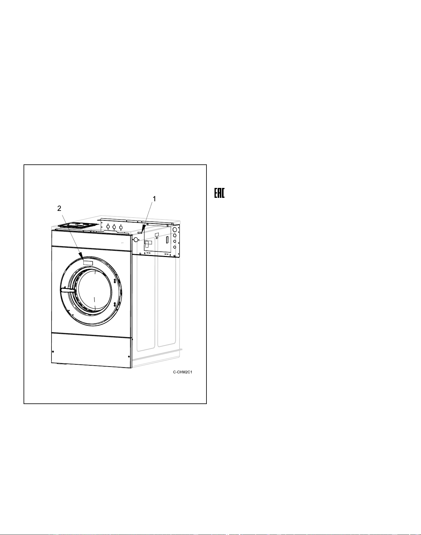
Serial Plate Location
The serial plate is located on the rear panel and inside the door of
the machine.
Always provide the machine’s serial number and model number
when ordering parts or when seeking technical assistance. Refer
to Figure 1 .
Model Example of Serial Plate Location
1. Serial Plate on Panel
2. Serial Plate on Door Frame
Figure 1
Replacement Parts
If literature or replacement parts are required, contact the source
from which the machine was purchased or contact Alliance Laun-
dry Systems at +1 (920) 748-3950 for the name and address of
the nearest authorized parts distributor.
Customer Service
For technical assistance, contact your local distributor or contact:
Alliance Laundry Systems
Shepard Street
P.O. Box 990
Ripon, WI 54971-0990
U.S.A.
www.alliancelaundry.com
Phone: +1 (920) 748-3121 Ripon, Wisconsin
Manufacturing Date
The manufacturing date for your unit can be found on the serial
number. The first two digits indicate the year. The third and
fourth digits indicate the month. For example, a unit with serial
number 1505000001 was manufactured in May 2015.
Introduction
©
Copyright, Alliance Laundry Systems LLC -
DO NOT COPY or TRANSMIT
21 Part No. F8619501ENR4
Downloaded from www.ManualsFile.com manuals search engine
Specifications and Dimensions
Specification 20 30 40 60 80 100
Overall Dimensions
Overall width, in. [mm] 26.0 [660] 29.0 [737] 30.6 [778] 34.1 [865] 41.5 [1054] 41.5 [1054]
Overall height, in [mm] 44.1 [1120] 46.1 [1171] 48.3 [1227] 51 [1295] 58.3 [1481] 58.3 [1481]
Overall depth, in. [mm] 30.9 [784] 35.3 [896] 42.3 [1073] 44.7 [1135] 47.1 [1196] 51.1 [1298]
Weight and Shipping Information
Net weight, lbs. [kg] 340 [154] 440 [200] 540 [245] 680 [308] 1250 [567] 1280 [581]
Standard shipping weight, lbs.
[kg]
380 [172] 480 [218] 580 [263] 720 [327] 1300 [590] 1330 [603]
Standard shipping volume, ft
3
[m
3
]
27 [0.76] 36 [1.01] 44 [1.24] 57 [1.61] 83 [2.35] 89 [2.52]
Standard shipping dimensions
(WxDxH), in. [mm]
28.0 x 33.8 x
49.4 [711 x
859 x 1255]
31.5 x 38.3 x
51.3 [800 x
973 x 1303]
32.5 x 43.5 x
53.6 [826 x
1105 x 1361]
37.5 x 46.9 x
56.3 [953 x
1191 x 1430]
44.0 x 54.5 x
59.6 [1118 x
1384 x 1514]
44.0 x 58.5 x
59.6 [1118 x
1486 x 1514]
Slat crate shipping weight, lbs.
[kg ]
460 [209] 580 [263] 680 [308] 840 [381] 1430 [649] 1460 [662]
Slat crate shipping volume, ft
3
[m
3
]
38 [1.08] 47 [1.33] 54 [1.52] 78 [2.20] 105 [2.97] 112 [3.17]
Slat crate shipping dimensions
(WxDxH), in. [mm]
32.5 x 36.8 x
55 [826 x 935
x 1397]
36.0 x 41.3 x
55.0 [914 x
1049 x 1397]
37.0 x 45.9 x
55.0 [940 x
1166 x 1397]
42.0 x 49.9 x
64.0 [1067 x
1267 x 1626]
48.5 x 57.5 x
65.1 [1232 x
1461 x 1654]
48.5 x 61.5 x
65.1 [1232 x
1562 x 1654]
Wash Cylinder Information
Cylinder diameter, in. [mm] 21.0 [533] 24.0 [610] 26.3 [668] 30.0 [762] 36.0 [914] 36.0 [914]
Cylinder depth, in. [mm] 13.8 [350] 16.0 [406] 20.3 [515] 22.0 [559] 21.9 [556] 25.9 [657]
Cylinder volume, ft
3
[l] 2.8 [79.3] 4.2 [119] 6.3 [178] 9.0 [255] 12.9 [365] 15.2 [430]
Cylinder capacity, lbs. [kg] 20 [9.1] 30 [13.1] 40 [18.1] 60 [27.2] 80 [36.3] 100 [45.4]
Perforation size, in. [mm] 0.188 [4.78] 0.188 [4.78] 0.188 [4.78] 0.188 [4.78] 0.188 [4.78] 0.188 [4.78]
Perforation open area, % 17.3 18.6 18.8 18.8 19.6 20.2
Door Opening Information
Door opening size, in. [mm] 11.6 [295] 14.3 [363] 16.3 [414] 16.3 [414] 18.5 [470] 18.5 [470]
Height of door bottom above
floor, in. [mm]
14.4 [365] 14.0 [356] 14.6 [370] 14.9 [379] 17.9 [455] 17.9 [455]
Height of door opening above
floor, in. [mm]
17.0 [432] 17.0 [431] 17.7 [451] 18.1 [460] 21.7 [551] 21.7 [551]
Table 1 continues...
Specifications and Dimensions
©
Copyright, Alliance Laundry Systems LLC -
DO NOT COPY or TRANSMIT
22 Part No. F8619501ENR4
Downloaded from www.ManualsFile.com manuals search engine
Specification 20 30 40 60 80 100
Power Consumption
Average power used per cycle,
kW-hr. (X-voltage, non-heat
models)
0.09 0.12 0.16 0.21 0.27 0.30
Estimated Building Heat Load
HVAC load Use 5% of total energy used per cycle.
Drive Train Information
Number of motors in drive
train
1 1 1 1 1 1
Drive motor power, hp [kW] 1 [0.75] 1 [0.75] 2 [1.5] 3 [2.25] 5 [3.75] 5 [3.75]
Cylinder Speeds
Gentle wash/reverse, RPM [G] 37 [0.4] 34 [0.4] 33 [0.4] 31 [0.4] 28 [0.4] 28 [0.4]
Wash/reverse, RPM [G] 51 [0.8] 48 [0.8] 46 [0.8] 43 [0.8] 39 [0.8] 39 [0.8]
Distribution, RPM [G] 92 [2.5] 86 [2.5] 82 [2.5] 77 [2.5] 70 [2.5] 70 [2.5]
Very low extract, RPM [G] 301 [27] 282 [27] 269 [27] 252 [27] 230 [27] 230 [27]
Low extract, RPM [G] 518 [80] 485 [80] 464 [80] 434 [80] 396 [80] 396 [80]
Medium extract, RPM [G] 579 [100] 542 [100] 518 [100] 485 [100] 443 [100] 443 [100]
High extract, RPM [G] 648 [125] 606 [125] 579 [125] 542 [125] 495 [125] 495 [125]
Very high extract, RPM [G] 710 [150] 664 [150] 635 [150] 594 [150] 542 [150] 542 [150]
Ultra high extract, RPM [G] 819 [200] 766 [200] 733 [200] 686 [200] 626 [200] 568 [165]
Direct Steam Heating (Optional)
Steam inlet connection size, in.
(NPT)
N/A N/A 1/2 1/2 1/2 1/2
Number of steam inlets N/A N/A 1 1 1 1
Maximum pressure, psi [kPa] N/A N/A 85 [570] 85 [570] 85 [570] 85 [570]
Required pressure, (min. - max.
psi [kPa] )
30-85
[200-570]
30-85
[200-570]
30-85
[200-570]
30-85
[200-570]
30-85
[200-570]
30-85
[200-570]
Steam re-
quired to raise
bath water
temperature
10°F/lbs.
[10°C/kg]
LOW N/A N/A 2.09 [0.94] 3.80 [1.63] 3.80 [1.72] 3.80 [1.72]
MED N/A N/A 2.40 [1.09] 4.65 [2.11] 4.65 [2.11] 5.49 [2.49]
HIGH N/A N/A 2.84 [1.29] 5.79 [2.63] 5.79 [2.63] 6.84 [3.10]
Average consumption per cy-
cle, BHP [kgf m]
N/A N/A 0.78 [59] 0.98 [75] 1.34 [102] 1.58 [120]
Table 1 continues...
Specifications and Dimensions
©
Copyright, Alliance Laundry Systems LLC -
DO NOT COPY or TRANSMIT
23 Part No. F8619501ENR4
Downloaded from www.ManualsFile.com manuals search engine
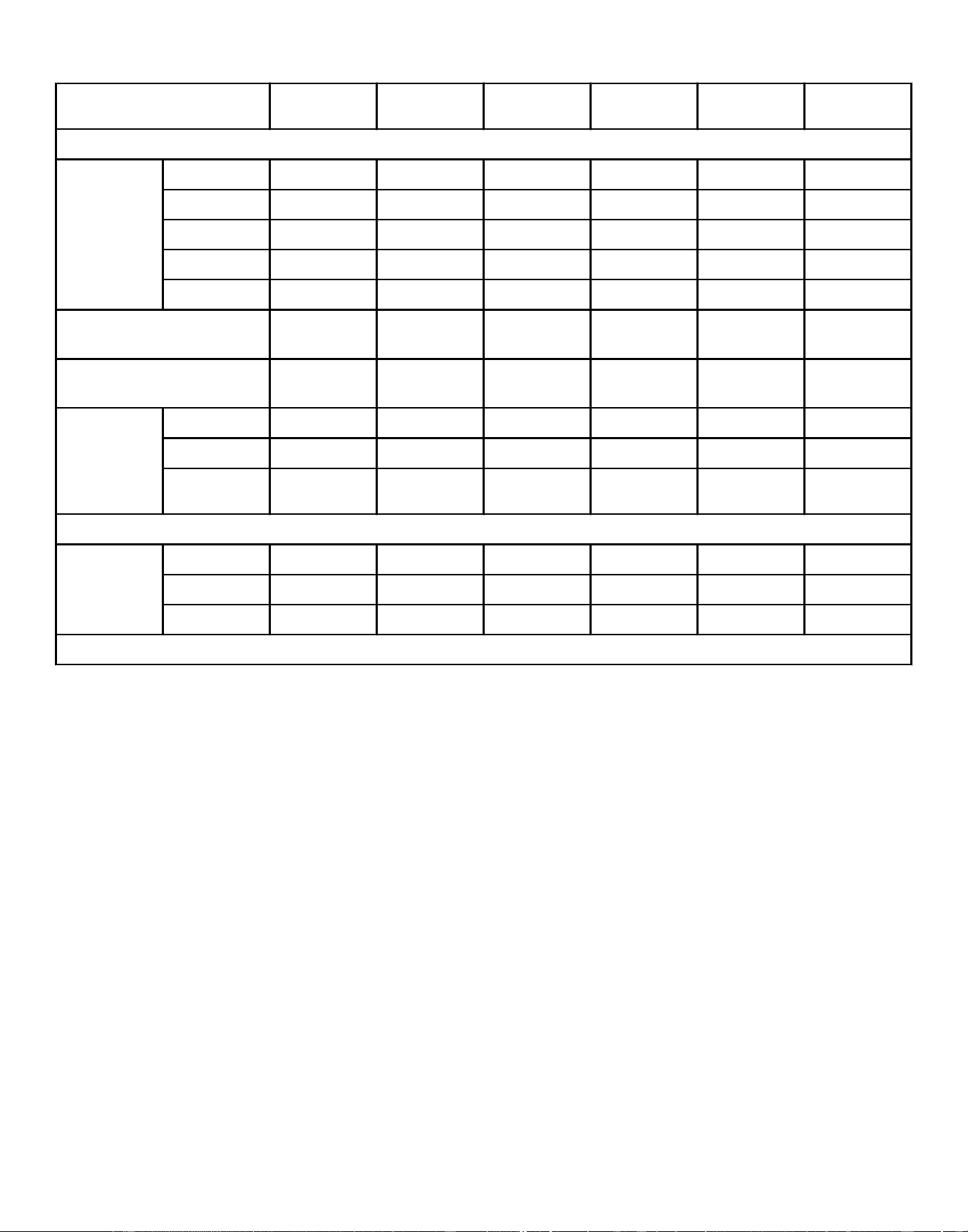
Specification 20 30 40 60 80 100
Electrical Heating (Optional)
Total electrical
heating ca-
pacity, kW
200V 5.4 5.4 10.8 10.8 19.1 19.1
240V 7.8 7.8 15.6 15.6 27.4 27.4
380V 6.5 6.5 13.0 13.0 17.2 17.2
415V 7.8 7.8 15.5 15.5 20.5 20.5
480V N/A N/A 15.6 15.6 27.4 27.4
Number of electrical heating el-
ements
3 3 6 6 6 6
Electrical heat element size,
kW
2.6 2.6 2.6 2.6 4.2 4.2
Time required
to raise bath
temperature,
minutes per
10°F [5.5°C]
LOW 1.690 2.545 1.792 2.648 2.101 2.436
MED 2.048 3.119 2.187 2.902 2.268 2.843
HIGH 2.368 3.693 2.394 3.269 2.643 3.031
Noise Emissions
dBA Wash 58 58 58 58 60 64
Extract (100G) 56 56 58 60 67 69
Extract (200G) 61 65 65 65 73 73
N/A = Not Applicable
Table 1
Specifications and Dimensions
©
Copyright, Alliance Laundry Systems LLC -
DO NOT COPY or TRANSMIT
24 Part No. F8619501ENR4
Downloaded from www.ManualsFile.com manuals search engine
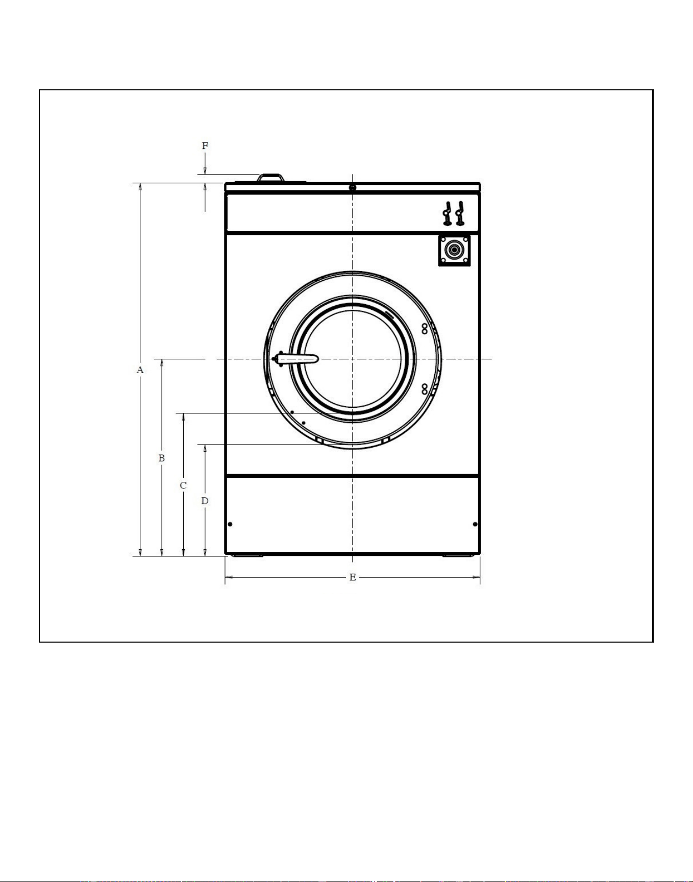
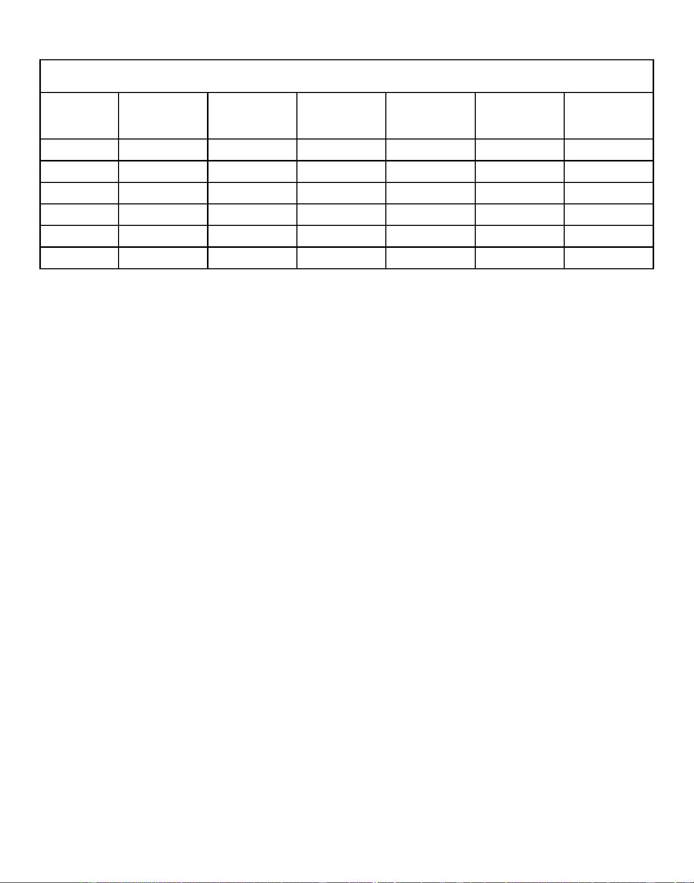
Machine Dimensions, in. [mm]
Specifica-
tion 20 30 40 60 80 100
A 43.0 [1092] 45.0 [1143] 47.2 [1199] 49.9 [1267] 57.2 [1453] 57.2 [1453]
B 23.0 [584] 24.0 [610] 26.0 [660] 26.4 [671] 30.9 [785] 30.9 [785]
C 17.0 [432] 17.0 [432] 17.7 [450] 18.1 [460] 21.7 [551] 21.7 [551]
D 14.4 [366] 14.0 [356] 14.6 [371] 14.9 [378] 17.9 [378] 17.9 [378]
E 26.0 [660] 29.0 [737] 30.6 [777] 34.1 [866] 41.5 [1054] 41.5 [1054]
F 1.1 [28] 1.1 [28] 1.1 [28] 1.1 [28] 1.1 [28] 1.1 [28]
Table 2
Specifications and Dimensions
©
Copyright, Alliance Laundry Systems LLC -
DO NOT COPY or TRANSMIT
26 Part No. F8619501ENR4
Downloaded from www.ManualsFile.com manuals search engine
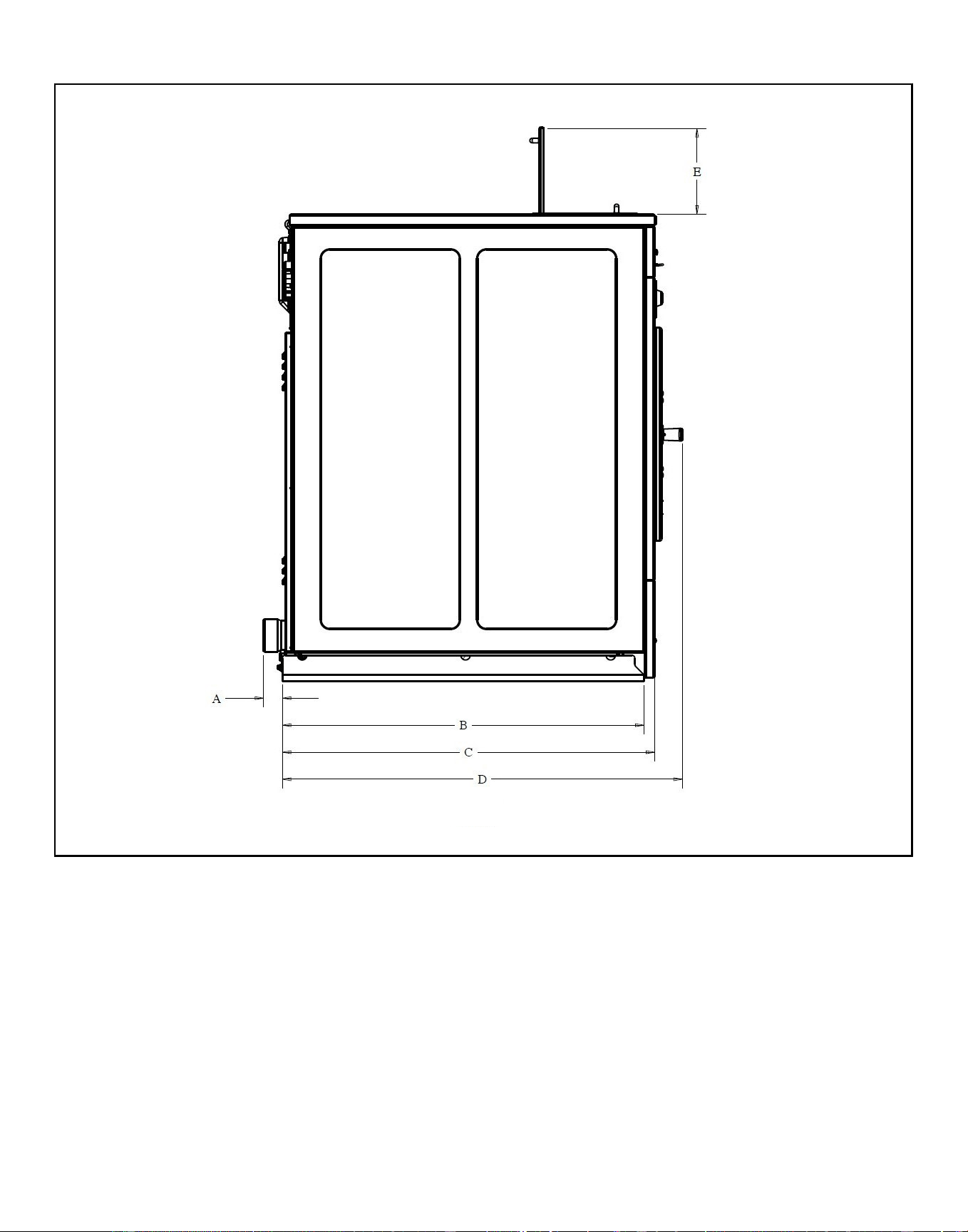
Machine Dimensions, in. [mm]
Specifica-
tion 20 30 40 60 80 100
A 2.0 [51] 2.0 [51] 2.0 [51] 2.0 [51] 1.1 [28] 1.1 [28]
B 26.8 [681] 31.5 [800] 35.5 [902] 38.6 [980] 39.2 [996] 39.2 [996]
C 27.3 [693] 31.8 [808] 37.0 [940] 39.5 [1003] 44.1 [1120] 48.1 [1222]
D 30.9 [785] 35.3 [897] 42.3 [1074] 44.7 [1135] 47.1 [1196] 51.1 [1298]
E 9.3 [236] 9.3 [236] 9.3 [236] 9.3 [236] 9.3 [236] 9.3 [236]
Door width 16.75 [426] 19.38 [492] 21.75 [552] 21.75 [552] 25.25 [641] 25.25 [641]
Table 3
Specifications and Dimensions
©
Copyright, Alliance Laundry Systems LLC -
DO NOT COPY or TRANSMIT
28 Part No. F8619501ENR4
Downloaded from www.ManualsFile.com manuals search engine
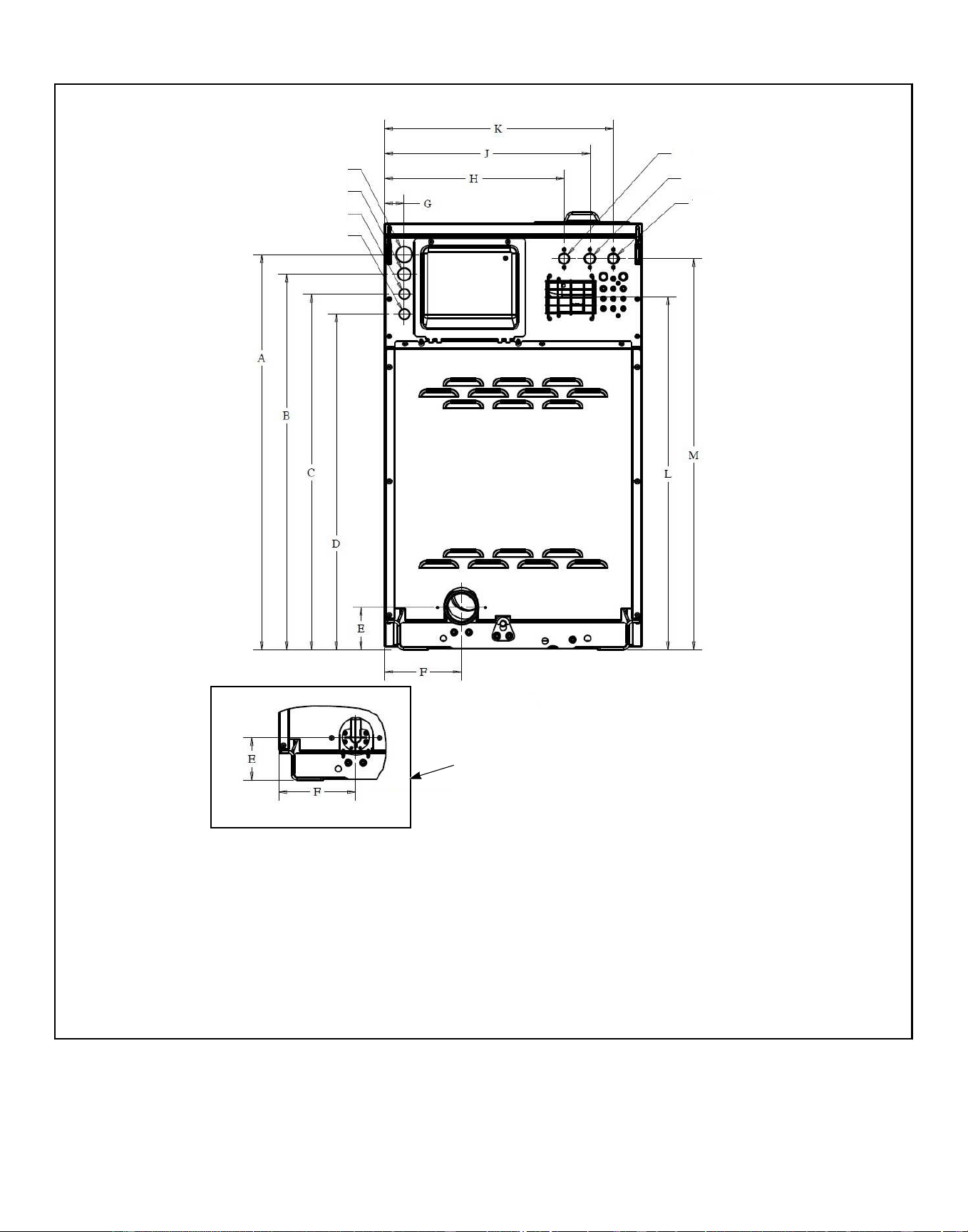
20-30 Models Rear View
CHM2565N_SVG
1
2
3
4
5
6
7
8
1. 1 1/2" Electrical
2. 1 1/8" Electrical
3. 7/8" Electrical
4. 7/8" Electrical
5. Compartment Cold Fill Valve
6. Compartment Hot Fill Valve
7. Cold Hard Water Valve or 3rd Water Inlet
8. Pump Drain View
Figure 4
Specifications and Dimensions
©
Copyright, Alliance Laundry Systems LLC -
DO NOT COPY or TRANSMIT
29 Part No. F8619501ENR4
Downloaded from www.ManualsFile.com manuals search engine
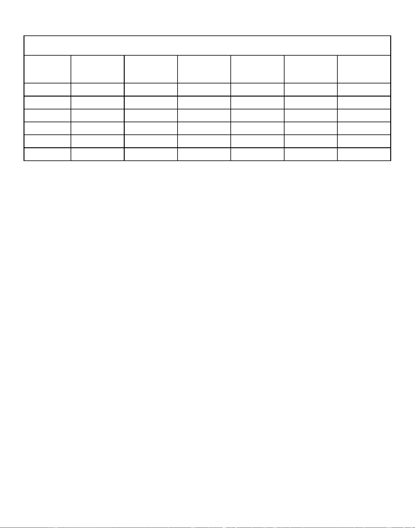
Machine Dimensions, in. [mm]
Specification 20 30
A 39.8 [1011] 41.8 [1062]
B 37.8 [960] 39.8 [1011]
C 35.8 [909] 37.8 [960]
D 33.8 [859] 35.8 [909]
E 3.9 [99] 4.3 [109]
F 7.8 [198] 9.3 [236]
G 2.0 [51] 2.0 [51]
H 18.1 [460] 21.1 [536]
J 20.7 [526] 23.7 [602]
K 23.1 [587] 26.1 [663]
L 39.4 [1001] 41.4 [1052]
M 35.6 [904] 37.5 [953]
Table 4
Specifications and Dimensions
©
Copyright, Alliance Laundry Systems LLC -
DO NOT COPY or TRANSMIT
30 Part No. F8619501ENR4
Downloaded from www.ManualsFile.com manuals search engine
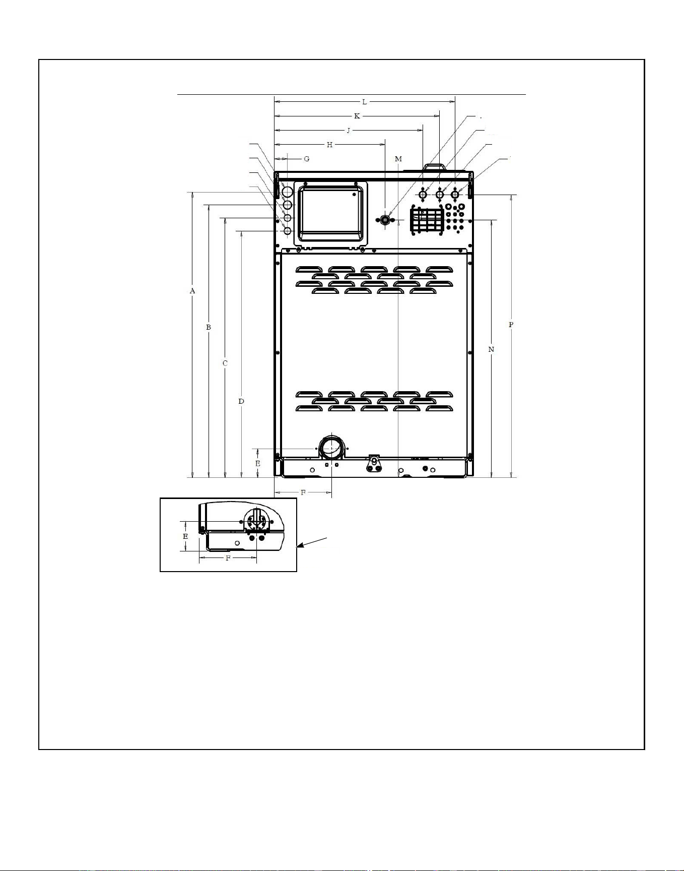
40 Models Rear View
CHM2566N_SVG
1
2
3
4
5
6
7
8
9
1. 1 1/2" Electrical
2. 1 1/8" Electrical
3. 7/8" Electrical
4. 7/8" Electrical
5. Steam Valve
6. Compartment Cold Fill Valve
7. Compartment Hot Fill Valve
8. Cold Hard Water Valve or 3rd Water Inlet
9. Pump Drain View
Figure 5
Specifications and Dimensions
©
Copyright, Alliance Laundry Systems LLC -
DO NOT COPY or TRANSMIT
31 Part No. F8619501ENR4
Downloaded from www.ManualsFile.com manuals search engine
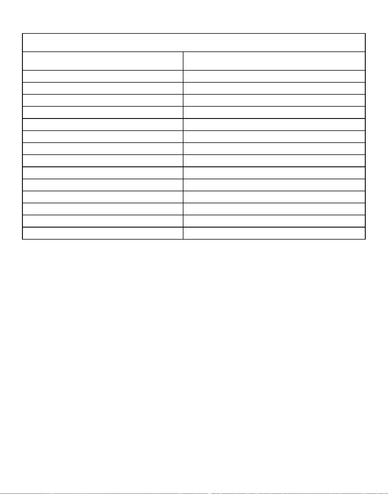
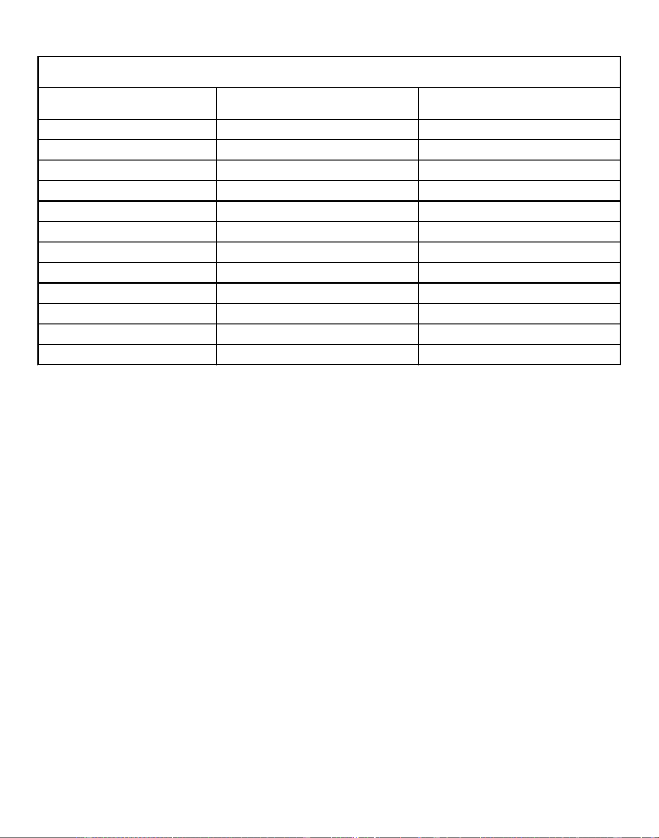
Machine Dimensions, in. [mm]
Specification 40
A 44.0 [1118]
B 42.0 [1067]
C 40.3 [1024]
D 38.0 [965]
E 4.5 [114]
F 8.8 [224]
G 17.0 [432]
H 2.0 [51]
J 22.8 [579]
K 25.4 [645]
L 27.7 [704]
M 39.7 [1008]
N 43.6 [1107]
P 39.7 [1008]
Table 5
Specifications and Dimensions
©
Copyright, Alliance Laundry Systems LLC -
DO NOT COPY or TRANSMIT
32 Part No. F8619501ENR4
Downloaded from www.ManualsFile.com manuals search engine
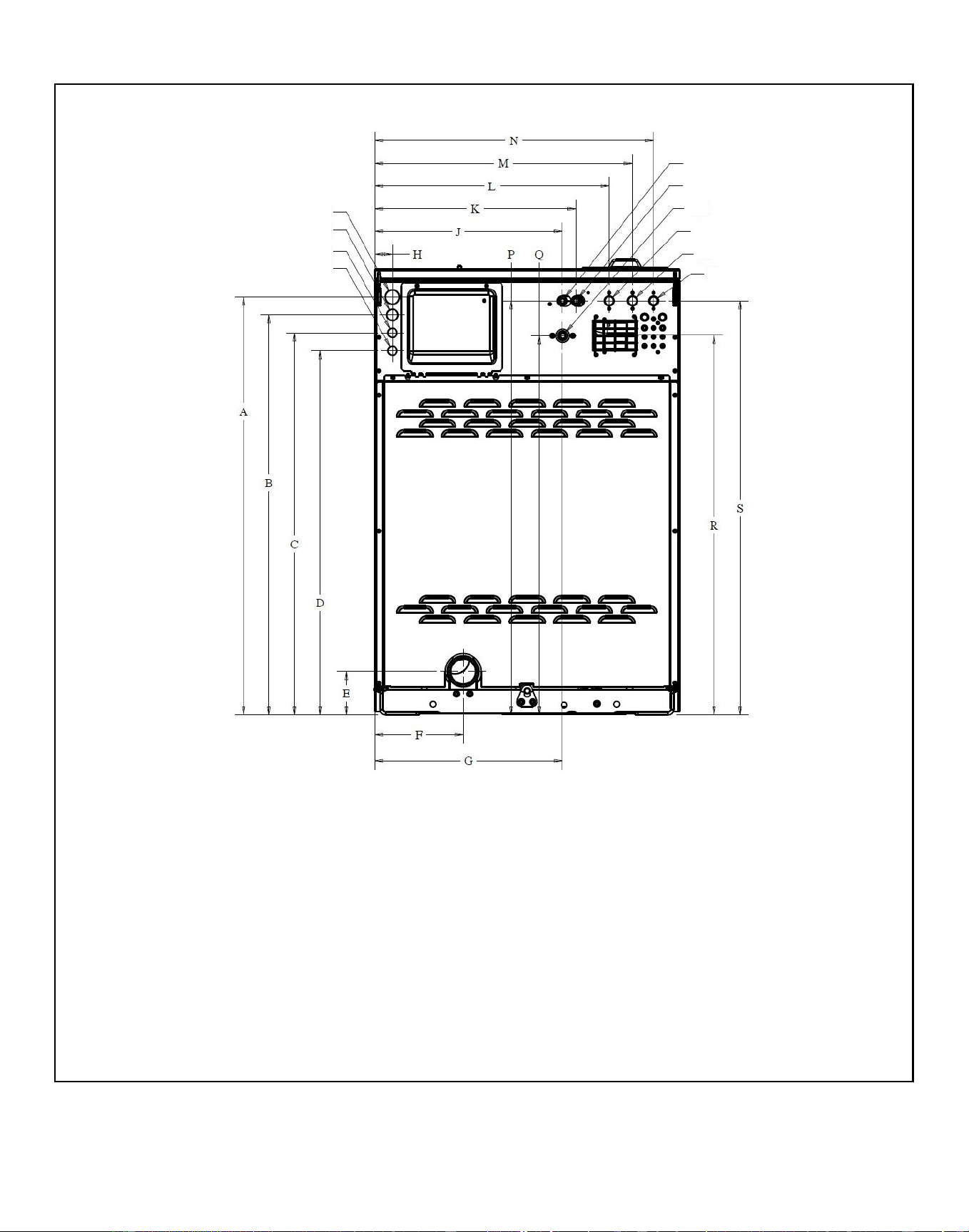
60-100 Models Rear View
CHM2567N_SVG
1
2
3
4
7
8
9
10
5
6
1. 1 1/2" Electrical
2. 1 1/8" Electrical
3. 7/8" Electrical
4. 7/8" Electrical
5. Tub Cold Fill Valve
6. Tub Hot Fill Valve
7. Steam Valve
8. Compartment Cold Fill Valve
9. Compartment Hot Fill Valve
10. Cold Hard Water Valve or 3rd Water Inlet
Figure 6
Specifications and Dimensions
©
Copyright, Alliance Laundry Systems LLC -
DO NOT COPY or TRANSMIT
33 Part No. F8619501ENR4
Downloaded from www.ManualsFile.com manuals search engine
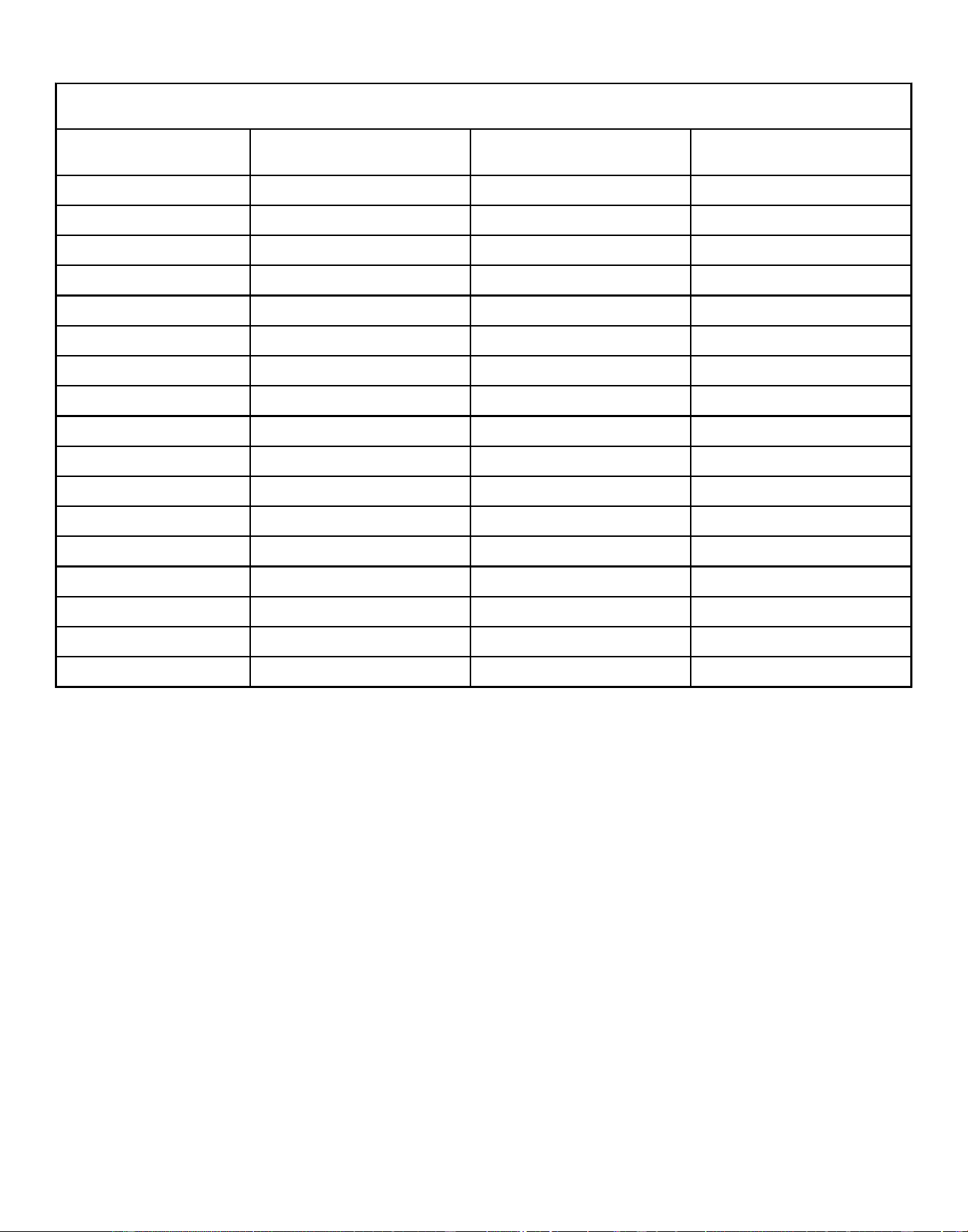
Machine Dimensions, in. [mm]
Specification 60 80 100
A 46.7 [1186] 54.0 [1372] 54.0 [1372]
B 44.7 [1135] 52.0 [1321] 52.0 [1321]
C 42.7 [1085] 50.0 [1270] 50.0 [1270]
D 40.7 [1034] 48.0 [1219] 48.0 [1219]
E 4.9 [124] 5.1 [130] 5.1 [130]
F 9.9 [251] 2.7 [69] 2.7 [69]
G 21.0 [533] 28.8 [732] 28.8 [732]
H 2.0 [51] 2.0 [51] 2.0 [51]
J 21.0 [533] 28.4 [721] 28.4 [721]
K 22.5 [572] 29.9 [759] 29.9 [759]
L 26.2 [665] 33.6 [853] 33.6 [853]
M 28.8 [732] 36.2 [919] 36.2 [919]
N 31.2 [792] 38.6 [980] 38.6 [980]
P 46.3 [1176] 52.6 [1336] 52.6 [1336]
Q 42.4 [1077] 49.7 [1262] 49.7 [1262]
R 46.3 [1176] 53.6 [1361] 53.6 [1361]
S 42.4 [1097] 49.7 [1262] 49.7 [1262]
Table 6
Specifications and Dimensions
©
Copyright, Alliance Laundry Systems LLC -
DO NOT COPY or TRANSMIT
34 Part No. F8619501ENR4
Downloaded from www.ManualsFile.com manuals search engine
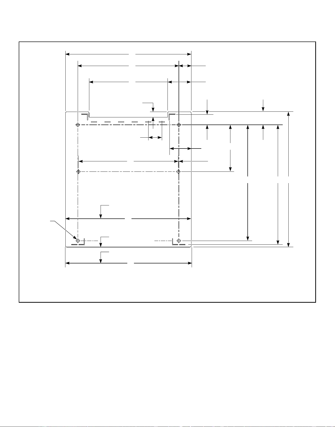
Mounting Bolt Hole Locations – 20 and 30 Models
20-30 Models (refer to Table 7 )
CHM2609N_SVG
Q
L
PON
M
K
J
I
F
G
H
E
C
B
D
A
S
2
1
R
3
1. Elevated Base Width
2. Front of Mounting Bolt Template
3. Machine Width
Figure 7
Specifications and Dimensions
©
Copyright, Alliance Laundry Systems LLC -
DO NOT COPY or TRANSMIT
35 Part No. F8619501ENR4
Downloaded from www.ManualsFile.com manuals search engine
Mounting Bolt Hole Locations – 20 and 30 Models, in. [mm]
Specification 20 30
A 26 [660] 29 [737]
B 20.875 [530] 23.886 [607]
C 2.562 [65] 2.558 [65]
D 16.25 [413] 18.87 [479]
E 4.875 [124] 5.065 [129]
F 1.12 [28] 1.033 [26]
G 2.15 [55] 1.81 [46]
H 2.71 [69] 2.37 [60]
I 2.8 [71] 2.813 [71]
J 4.5 [114] 4.51 [114]
K 9.638 [245] 10.5 [267]
L 20.649 [525] 23.5 [597]
M 0.113 [3] 0.188 [5]
N 23.938 [608] 28.938 [735]
O 24.69 [627] 29.69 [754]
P 27.95 [710] 32.38 [597]
Q 26 [660] 29 [737]
R 0.641 [16] 0.641 [16]
Table 7
Specifications and Dimensions
©
Copyright, Alliance Laundry Systems LLC -
DO NOT COPY or TRANSMIT
36 Part No. F8619501ENR4
Downloaded from www.ManualsFile.com manuals search engine
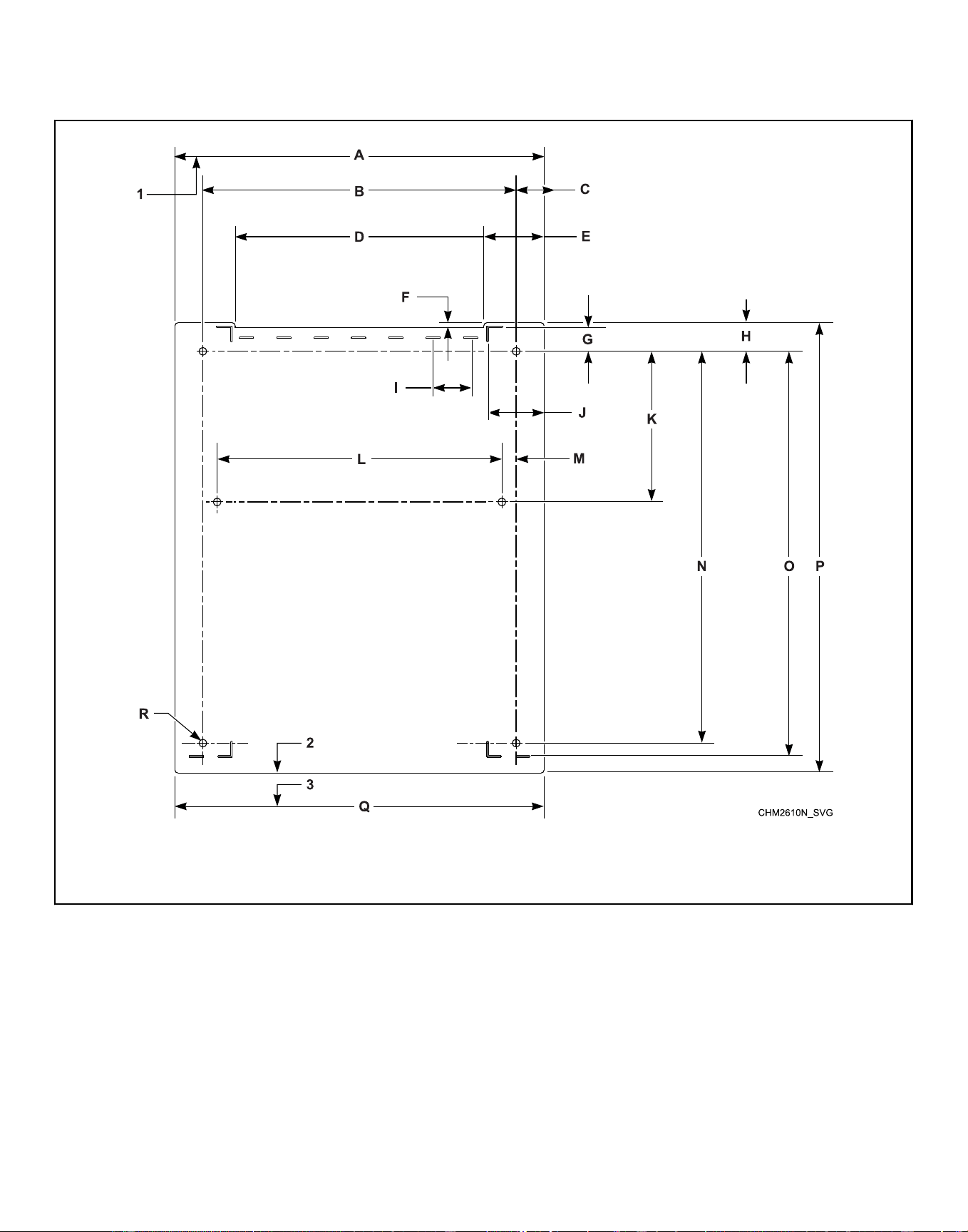
Mounting Bolt Hole Locations - 40 and 60 Models
40 and 60 Models (refer to Table 8 )
1. Elevated Base Width
2. Front of Mounting Bolt Template
3. Machine Width
Figure 8
Specifications and Dimensions
©
Copyright, Alliance Laundry Systems LLC -
DO NOT COPY or TRANSMIT
37 Part No. F8619501ENR4
Downloaded from www.ManualsFile.com manuals search engine
Mounting Bolt Hole Locations - 40 and 60 Models, in. [mm]
Specification 40 60
A 30.63 [778] 34.06 [865]
B 26 [660] 30 [762]
C 2.315 [59] 2.03 [52]
D 20.63 [524] 23.39 [594]
E 5 [127] 5.34 [136]
F 0.422 [11] 0.614 [16]
G 1.98 [50] 1.75 [44]
H 2.37 [60] 2.37 [60]
I 3.1 [79] 3.28 [83]
J 4.63 [118] 4.96 [126]
K 12.5 [318] 11.927 [303]
L 23.626 [600] 27.5 [699]
M 1.187 [30] 1.25 [32]
N 32.5 [826] 36 [914]
O 33.54 [852] 36.87 [699]
P 37.36 [949] 40.7 [1034]
Q 30.6 [777] 34.1 [866]
R 0.614 [16] 0.641 [16]
Table 8
Specifications and Dimensions
©
Copyright, Alliance Laundry Systems LLC -
DO NOT COPY or TRANSMIT
38 Part No. F8619501ENR4
Downloaded from www.ManualsFile.com manuals search engine
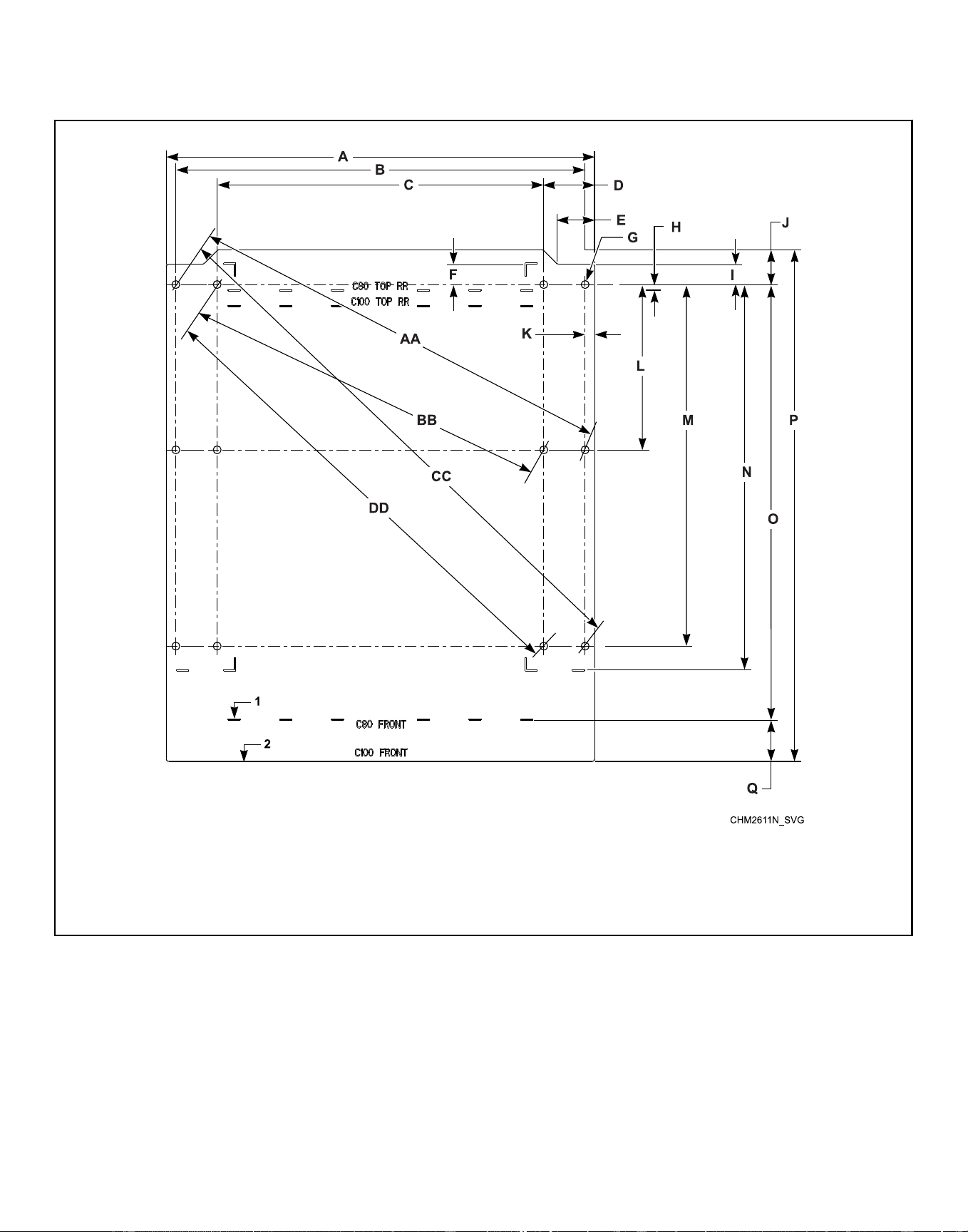
Mounting Bolt Hole Locations – 80 and 100 Models
80 and 100 Models (refer to Table 9 )
NOTE: For single machine installations or two machines installed back to back, use the outside bolt holes
marked “A”. For multiple machines installed side by side with minimum clearance, use the inside bolt holes
marked “B”.
1. Front of Mounting Bolt Template
Figure 9
Specifications and Dimensions
©
Copyright, Alliance Laundry Systems LLC -
DO NOT COPY or TRANSMIT
39 Part No. F8619501ENR4
Downloaded from www.ManualsFile.com manuals search engine
Mounting Bolt Hole Locations – 80 and 100 Models, in. [mm]
Specification 80 100
A 41.5 [1054] 41.5 [1054]
B 39.62 [1006] 39.62 [1006]
C 31.62 [803] 31.62 [803]
D 4.94 [124] 4.94 [124]
E 3.612 [92] 3.612 [92]
F 1.96 [50] 1.96 [50]
G 0.766 [19] 0.766 [19]
H 0.508 [13] 0.508 [13]
I 1.96 [50] 1.96 [50]
J 3.38 [86] 3.38 [86]
K 0.94 [24] 0.94 [24]
L 16 [406] 16 [406]
M 35 [889] 35 [889]
N 37.28 [947] 37.28 [947]
O 42.16 [1071] 42.16 [1071]
P 49.54 [1258] 49.54 [1258]
Q 4 [102] 4 [102]
AA Outside 42.72 [1085] 42.72 [1085]
BB Inside 35.43 [900] 35.43 [900]
CC Outside 52.86 [1342] 52.86 [1342]
DD Inside 47.16 [1197] 47.16 [1197]
Table 9
Specifications and Dimensions
©
Copyright, Alliance Laundry Systems LLC -
DO NOT COPY or TRANSMIT
40 Part No. F8619501ENR4
Downloaded from www.ManualsFile.com manuals search engine
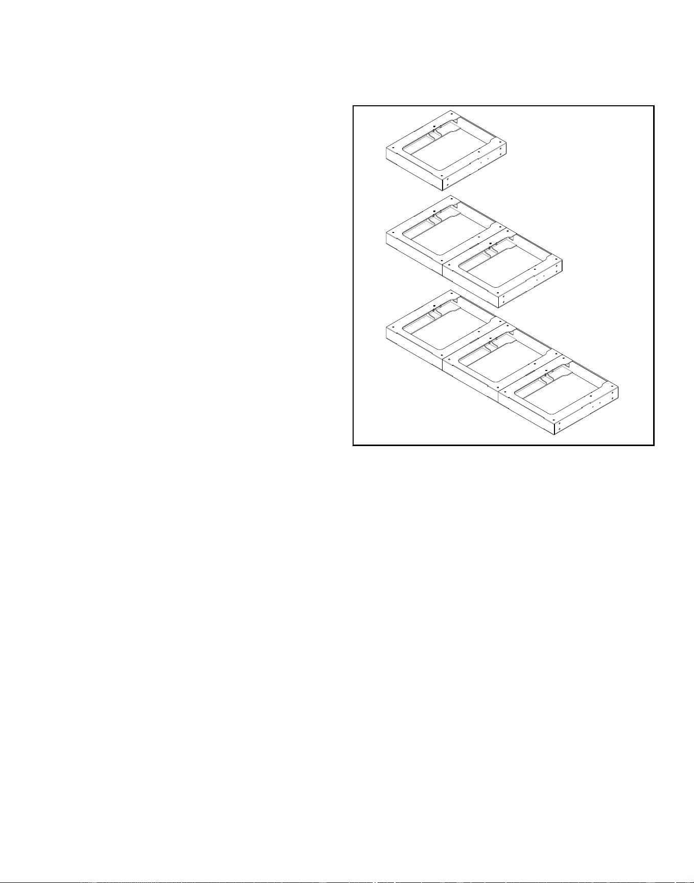
Installation
Foundation Options
A minimum 3500 psi (refer to rating per supplier) reinforced con-
crete set on a prepared bed is required for all new machine instal-
lations.
NOTE: Do not mount on wooden floors, tile floors, ele-
vated floor levels, stacked multiple base frames, or
over basements or crawl spaces because of the high
extract speed and the G-forces exerted. For 80 models
and larger, do not mount on metal base frames.
Thoroughness of detail must be stressed with all foundation work
to ensure a stable unit installation, eliminating possibilities of ex-
cessive vibration during extract.
For new foundations a mounting bolt template is available at ex-
tra cost or use machine base if available.
The machine must be anchored to a smooth level surface so that
the entire base of the machine is supported and rests on the
mounting surface.
IMPORTANT: Do not permanently support the machine
on only four points with spacers. Grouting is required
and spacers must be removed.
Machine Installation on Existing Floor
The existing floor slab must be reinforced concrete without voids
under slab and meet depth requirements per Table 19 . If the floor
meets these requirements and an elevated pad is NOT desired, re-
fer to Figure 18 and proceed to Machine Mounting and Grouting.
If the floor does not meet these requirements and an elevated pad
is NOT desired, refer to Figure 21 and proceed to Machine
Mounting and Grouting.
Elevated Pad Installation on Existing Floor
The existing floor slab must meet minimum requirements shown
in Foundation Requirements per machine. The floor must be rein-
forced concrete without voids under slab. If the slab meets these
requirements and an elevated pad is desired, refer to Figure 20
and proceed to Machine Mounting and Grouting.
Elevated Base Frame Installation on Existing
Floor
The existing floor slab must meet minimum requirements shown
in Machine Foundation and Pad Installation per machine. The
floor must be reinforced concrete without voids under slab. Refer
to Figure 18 and Figure 19 . If the slab does not meets these re-
quirements and an elevated base frame is desired, refer to Figure
21 . Proceed to Machine Mounting and Grouting.
CHM2412N_SVG
Figure 10
New Foundation
If the existing floor slab does not meet the single machine foun-
dation requirements per model and/or a new monolithic founda-
tion is desired, refer to Figure 19 and proceed to Foundation and
Pad Installation.
Installation
©
Copyright, Alliance Laundry Systems LLC -
DO NOT COPY or TRANSMIT
41 Part No. F8619501ENR4
Downloaded from www.ManualsFile.com manuals search engine

Isolated Pad Installation
This type of installation is NOT recommended. Installer MUST
consult a Structural Engineer for concrete specifications and re-
quirements for installations that will not be tied into adjacent
foundations.
IMPORTANT: The above instructions and recommenda-
tions are conservative specifications for a typical in-
stallation based on consultations with a structural en-
gineer. Alliance Laundry Systems stands behind all in-
stallations meeting these specifications. For alternate
installation specifications based on your soil type, lo-
cation, building structure, unique floor geometry, ma-
chine types, and utilities, consult a structural engineer
in your local area.
Foundation and Pad Installation
A concrete pad may be constructed to elevate a machine. Care
must be exercised in the design of the pad due to the force exert-
ed by the machine during extract. This concrete pad, recommend-
ed not to exceed 8 inches [203 mm] above existing floor, must be
placed, reinforced with rebar and tied to the existing floor. Refer
to Floor Layout and Pad Dimensions and Foundation Require-
ments sections for multiple machine installations.
IMPORTANT: Do NOT install a pad on top of the exist-
ing floor. The foundation and pad must be constructed
and tied together as one piece.
If the existing floor is not reinforced concrete at least 12 inches
[305 mm] thick, an elevated pad is desired or multiple machines
are to be installed, the following steps must be performed (refer
to Foundation Requirements):
1. Cut a hole through the existing floor that is larger on all sides
than the machine base, refer to Floor Layout and Pad Dimen-
sions .
2. Excavate to a depth as indicated in Table 18 from the top of
the existing floor.
3. If installing a foundation with elevated pad, prepare a form
for the above-ground portion of the foundation. Verify that the
top of the foundation is level. The height of the foundation
pad must not exceed 8 inches [203 mm] above the existing
floor.
4. Backfill with clean fill dirt.
5. Compact backfill, making sure to allow for correct concrete
thickness.
6. Drill holes (refer to manufacturer’s requirements for drill hole
size) for the perimeter reinforcing bar at a depth of 2-1/2 in-
ches [64 mm] into the existing floor. The reinforcing should
be 12 inches [305 mm] on center each way around entire pe-
rimeter.
7. Clean out debris from each reinforcing bar hole.
8. Fill half the hole depth with acrylic adhesive.
NOTE: Procure acrylic adhesive rated for commer-
cial-grade vibratory machine installations
9. Using #4 [60 ksi] reinforcing bar, tie new pad to existing floor
making sure to tie reinforcing bars at the intersections and us-
ing proper reinforcing bar supports to hold bars at the proper
depth in the pad.
10. Allow adhesive around reinforcing bar to cure properly, refer
to adhesive manufacturer for recommended cure times.
11. Completely fill with 3500 psi concrete up to the existing
foundation level plus any added level (maximum of 8 inch
[203 mm]) for the desired elevated pad. The concrete must be
poured so that the entire foundation and pad cures as one
piece.
12. Allow concrete to cure, refer to manufacturer’s recommended
cure times.
13. Using a mounting bolt template or machine base, mark where
the holes should be drilled to mount the machine.
NOTE: As an alternate method, cast in the Grade 5
(minimum SAE rating), 5/8 inch [16 mm] for 20-60
models and 3/4 inch [19 mm] for 80 and 100 anchor
bolts as the concrete is poured, refer to Figure 2 and
Table 1 .
14. Proceed to Machine Mounting and Grouting.
Installation
©
Copyright, Alliance Laundry Systems LLC -
DO NOT COPY or TRANSMIT
42 Part No. F8619501ENR4
Downloaded from www.ManualsFile.com manuals search engine
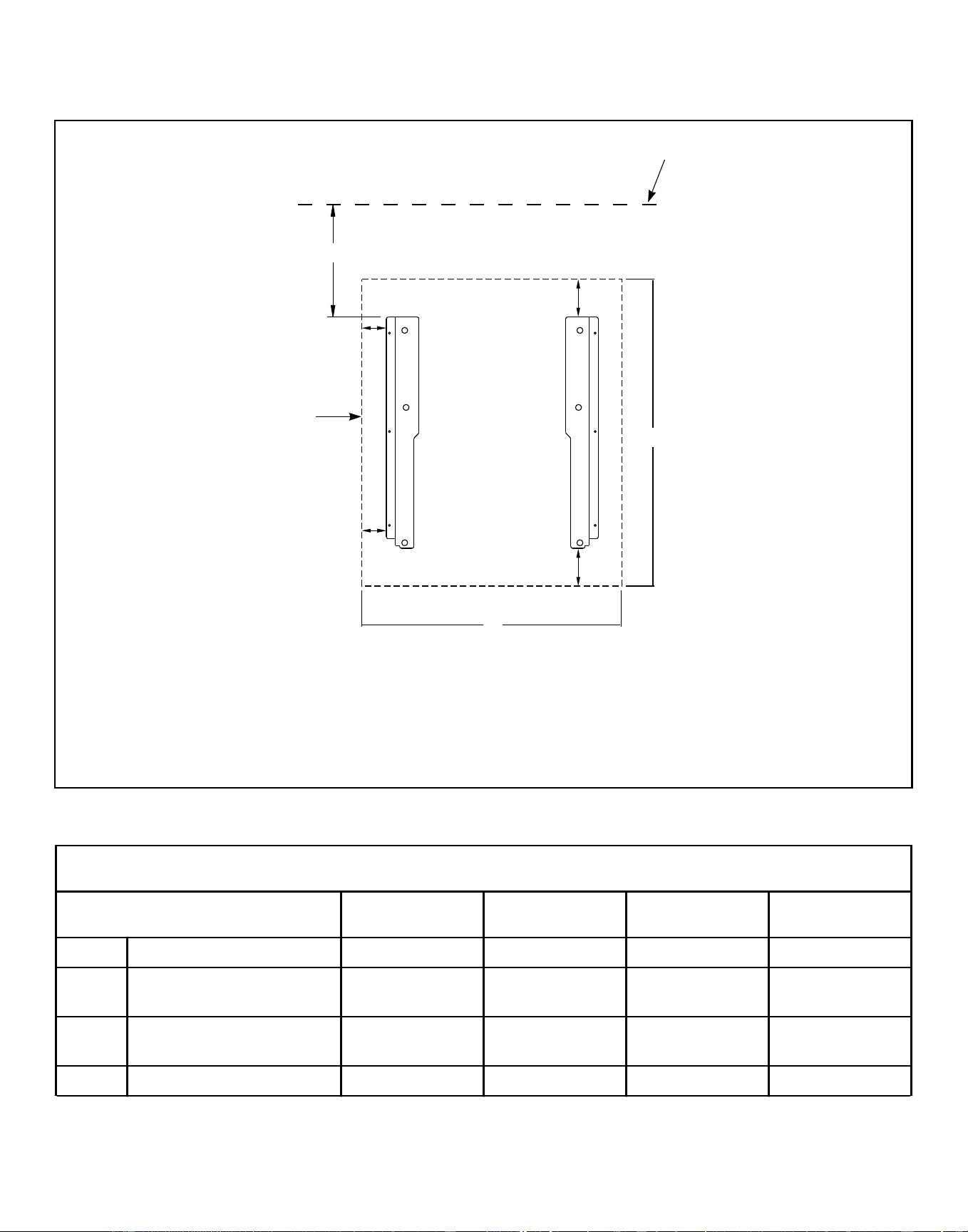
Floor Layout and Pad Dimensions
Dimensional Clearances - Single Machine Mount - 20-60 Pound [9.1-27.2 Kg] Models (refer to Table 11 )
CHM2504N_SVG
1
2
3
4
5
A
C
C
B
B
D
E
1. Wall
2. Rear Edge of Pad
3. Side Edge of Pad
4. Machine 1
5. Front Edge of Pad
Figure 11
Dimensional Clearances - Single Machine Mount - 20-60 Pound [9.1-27.2 Kg] Models, in. [mm]
Description 20 30 40 60
A Distance to wall (minimum) 24 [610] 24 [610] 24 [610] 24 [610]
B Distance of machine base to
edge of pad (minimum)
3.44 [87] 4 [102] 3.99 [101] 5.99 [152]
C Distance of machine base to
edge of pad (minimum)
2.52 [64] 2.51 [64] 2.81 [71] 5.18 [131]
D Length of pad (minimum) 34.8 [884] 39.5 [1003] 43.5 [1105] 50.6 [1285]
Table 11 continues...
Installation
©
Copyright, Alliance Laundry Systems LLC -
DO NOT COPY or TRANSMIT
43 Part No. F8619501ENR4
Downloaded from www.ManualsFile.com manuals search engine
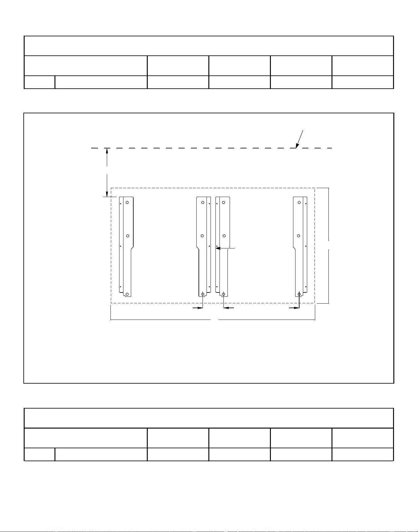
Dimensional Clearances - Single Machine Mount - 20-60 Pound [9.1-27.2 Kg] Models, in. [mm]
Description 20 30 40 60
E Width of pad (minimum) 31.4 [798] 34.4 [874] 36.5 [927] 44.8 [1138]
Table 11
Dimensional Clearances - Side-by-Side Mount - 20-60 Pound [9.1-27.2 Kg] Models (refer to Table 12 )
CHM2505N_SVG
C
D
1
2
E
3
5
2
4
5
A
B B
1. Wall
2. Rear Edge of Pad
3. Machine 1
4. Machine 2
5. Front Edge of Pad
Figure 12
Dimensional Clearances - Side-by-Side Mount - 20-60 Pound [9.1-27.2 Kg] Models, in. [mm]
Description 20 30 40 60
A Distance to wall (minimum) 24 [610] 24 [610] 24 [610] 24 [610]
Table 12 continues...
Installation
©
Copyright, Alliance Laundry Systems LLC -
DO NOT COPY or TRANSMIT
44 Part No. F8619501ENR4
Downloaded from www.ManualsFile.com manuals search engine
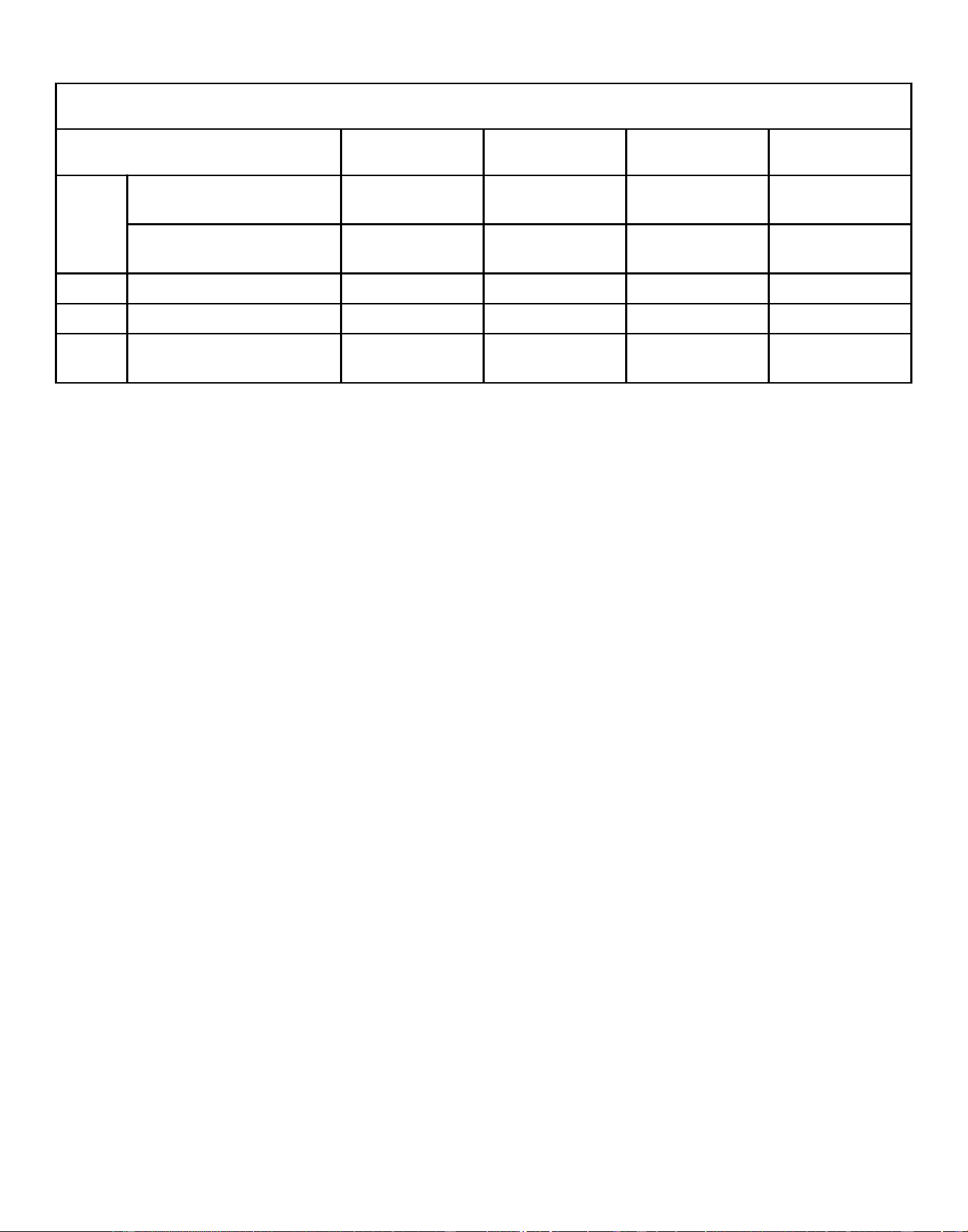
Dimensional Clearances - Side-by-Side Mount - 20-60 Pound [9.1-27.2 Kg] Models, in. [mm]
Description 20 30 40 60
B Mounted without bases (mini-
mum)
5.14 [131] 5.12 [130] 4.63 [118] 4.06 [103]
Mounted with bases (mini-
mum)
5.5 [139] 5.5 [139] 4.88 [124] 4.44 [112]
C Length of pad (minimum) 34.8 [884] 39.5 [1003] 43.5 [1105] 50.6 [1285]
D Width of pad (minimum) 57.54 [1462] 63.52 [1613] 67.38 [1711] 78.98 [2006]
E Side clearance between ma-
chines
.5 [13] .5 [13] .5 [13] .5 [13]
Table 12
Installation
©
Copyright, Alliance Laundry Systems LLC -
DO NOT COPY or TRANSMIT
45 Part No. F8619501ENR4
Downloaded from www.ManualsFile.com manuals search engine
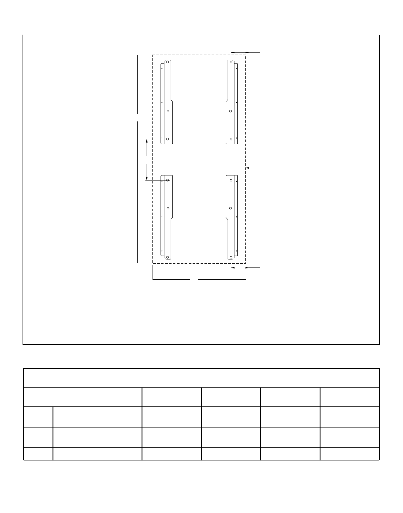
Dimensional Clearances - Back-to-Back Mount - 20-60 Pound [9.1-27.2 Kg] Models (refer to Table 13 )
CHM2506N_SVG
1
2
3
3
4
1
A
B
B
D
C
5
1. Front-facing Edge of Pad
2. Machine 2
3. Rear of Machine
4. Machine 1
5. Side Edge of Pad or Wall
Figure 13
Dimensional Clearances - Back-to-Back Mount - 20-60 Pound [9.1-27.2 Kg] Models, in. [mm]
Description 20 30 40 60
A Adjacent rear bolt spacing
(minimum)
28.3 [719] 27.6 [702] 28.0 [710] 27.5 [699]
B Distance from front bolt to
edge of pad (minimum)
5.26 [134] 5.26 [134] 6.19 [157] 8.9 [226]
C Length of pad (minimum) 88.63 [2251] 98.37 [2499] 115.23 [2927] 119.48 [3035]
Table 13 continues...
Installation
©
Copyright, Alliance Laundry Systems LLC -
DO NOT COPY or TRANSMIT
46 Part No. F8619501ENR4
Downloaded from www.ManualsFile.com manuals search engine
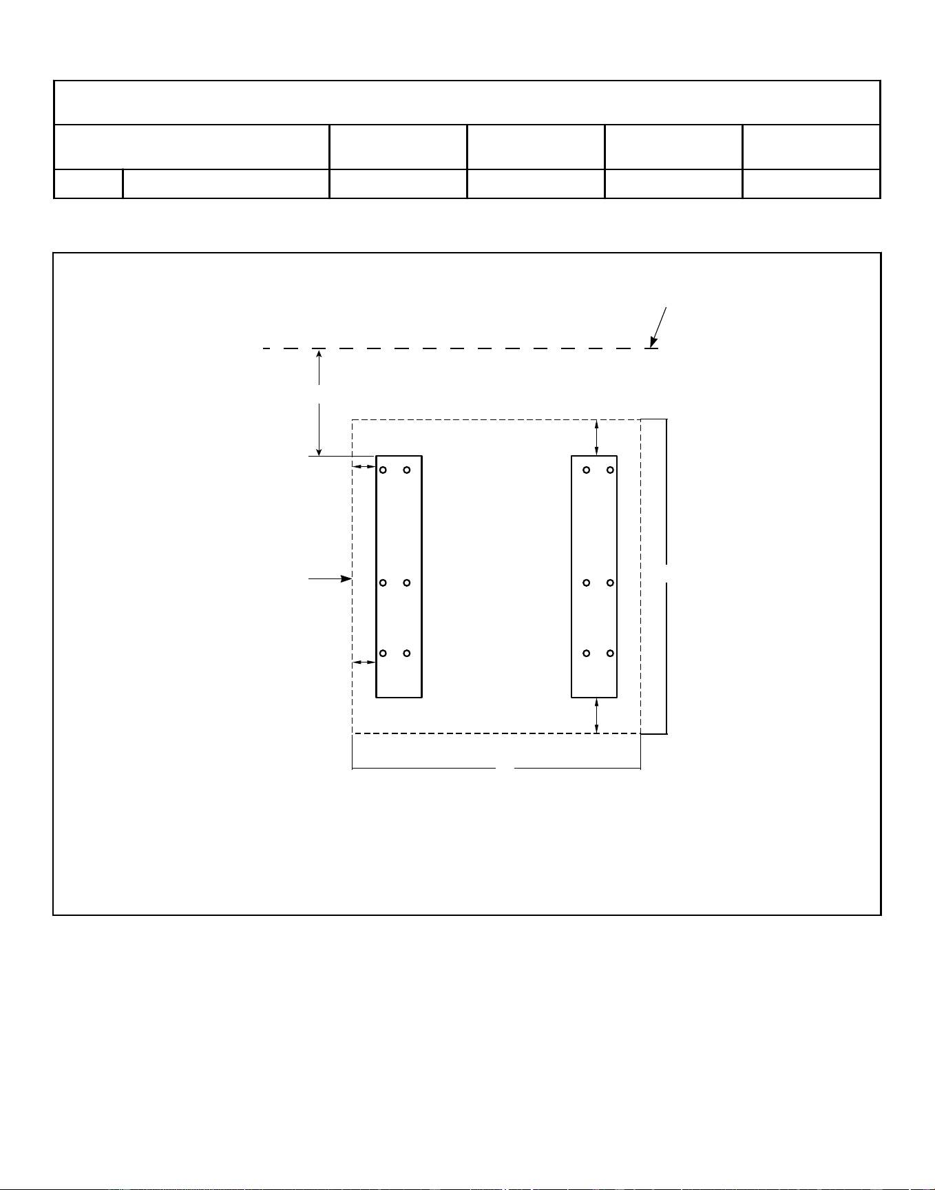
Dimensional Clearances - Back-to-Back Mount - 20-60 Pound [9.1-27.2 Kg] Models, in. [mm]
Description 20 30 40 60
D Width of pad (minimum) 31.4 [798] 34.4 [874] 36.5 [927] 44.8 [1138]
Table 13
Dimensional Clearances - Single Machine Mount - 80 and 100 Pound [36.3 and 45.4 Kg] Models (refer to Table
14 )
CHM2519N_SVG
D
E
1
2
3
4
5
A
C
C
B
B
1. Wall
2. Rear Edge of Pad
3. Side Edge of Pad
4. Machine 1
5. Front Edge of Pad
Figure 14
Installation
©
Copyright, Alliance Laundry Systems LLC -
DO NOT COPY or TRANSMIT
47 Part No. F8619501ENR4
Downloaded from www.ManualsFile.com manuals search engine
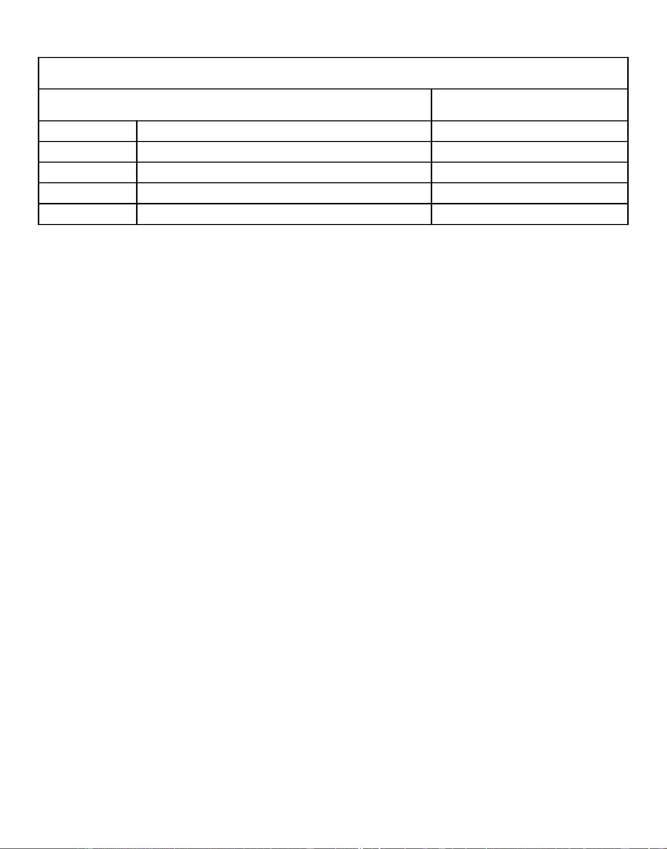
Single Machine Mount - 80 and 100 Pound [36.3 and 45.4 Kg] Models, in. [mm]
Description 80-100
A Distance to wall (minimum) 24 [610]
B Distance of machine base to edge of pad (minimum) 4.98 [126]
C Distance of machine base to edge of pad (minimum) 8 [203]
D Length of pad (minimum) 49.2 [1250]
E Width of pad (minimum) 57.5 [1461]
Table 14
Installation
©
Copyright, Alliance Laundry Systems LLC -
DO NOT COPY or TRANSMIT
48 Part No. F8619501ENR4
Downloaded from www.ManualsFile.com manuals search engine
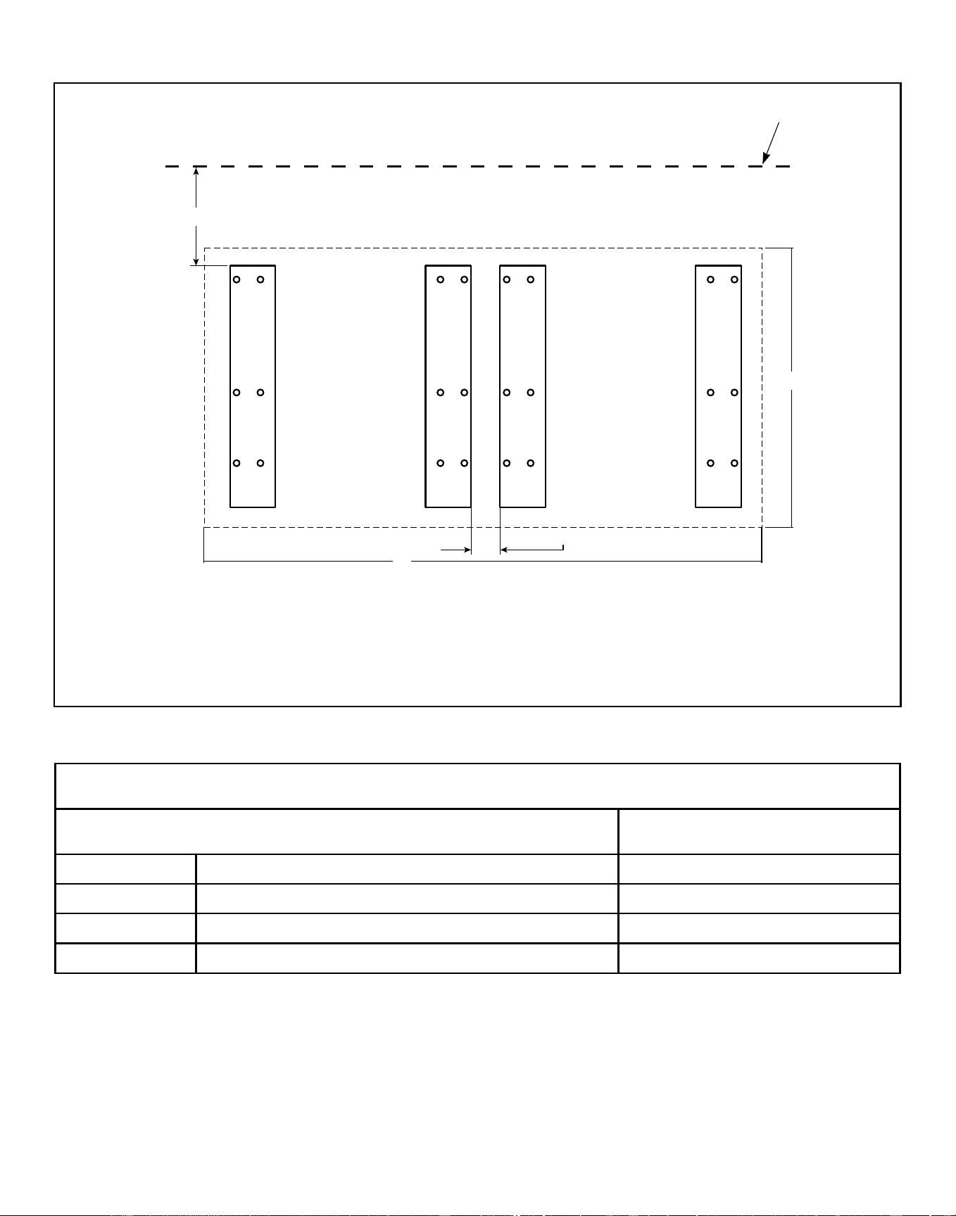
Dimensional Clearances - Side by Side Mount - 80 and 100 Pound [36.3 and 45.4 Kg] Models (refer to Table 15 )
CHM2520N_SVG
C
D
1
2
3
5
2
4
5
A
B
1. Wall
2. Rear Edge of Pad
3. Machine 1
4. Machine 2
5. Front Edge of Pad
Figure 15
Standard Mount Side-by-Side - 80 and 100 Pound [36.3 and 45.4 Kg] Models, in. [mm]
Description 80-100
A Distance to wall (minimum) 24 [610]
B Adjacent unit spacing (minimum) 6 [152]
C Length of pad (minimum) 49.2 [1250]
D Width of pad (minimum) 99.5 [2527]
Table 15
Installation
©
Copyright, Alliance Laundry Systems LLC -
DO NOT COPY or TRANSMIT
49 Part No. F8619501ENR4
Downloaded from www.ManualsFile.com manuals search engine
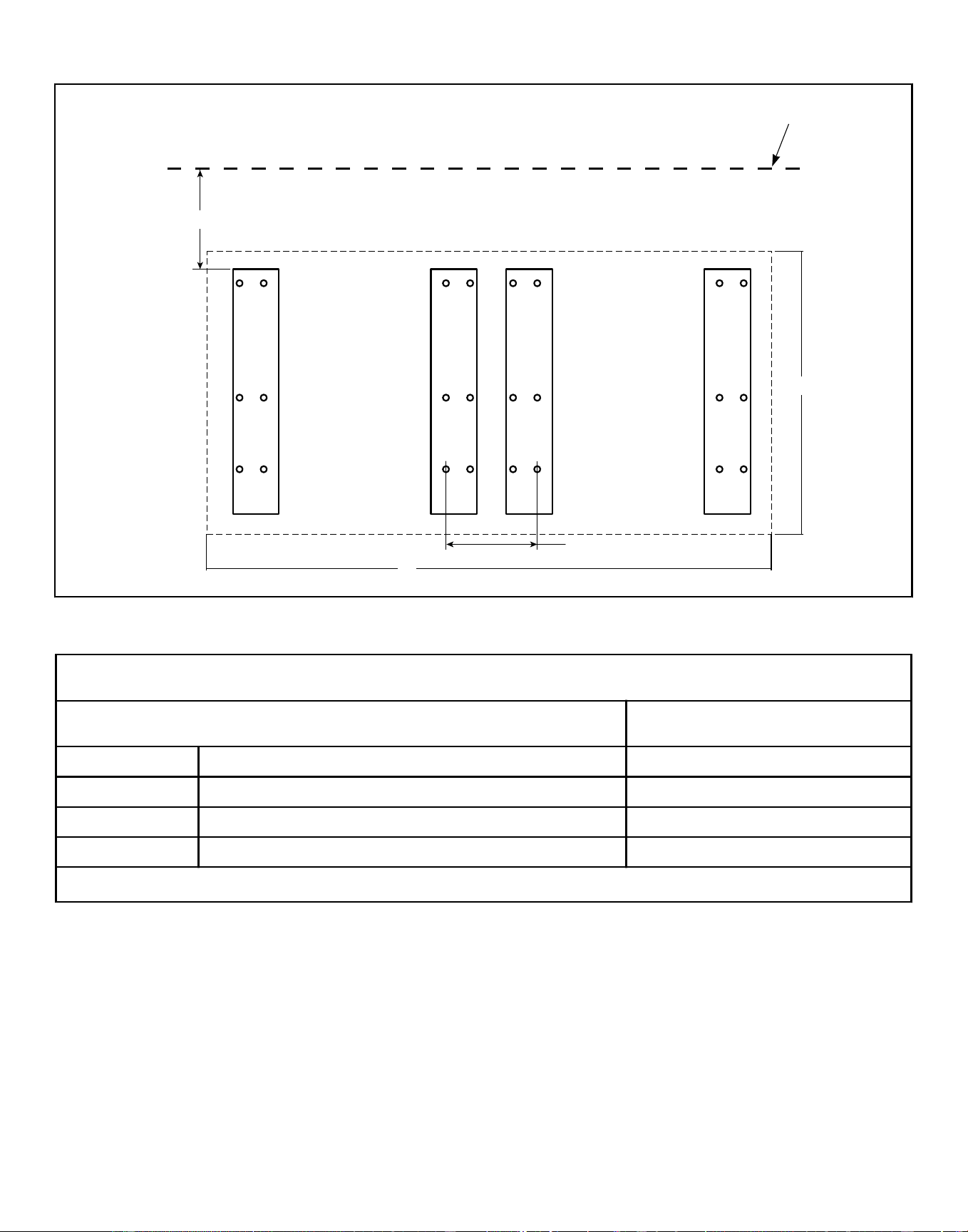
Close Mount Side-by-Side - 80 and 100 Pound [36.3 and 45.4 Kg] Models (refer to Table 15 )
CHM2521N_SVG
C
D
1
2
3
5
2
4
5
A
B
Figure 16
Close Mount Side-by-Side - 80 and 100 Pound [36.3 and 45.4 Kg] Models, in. [mm]
Description 80-100
A Distance to wall (minimum) 24 [610]
B Adjacent unit bolt spacing (minimum) 10.38 [264]
C Length of pad (minimum) 49.2 [1250]
D Width of pad (minimum) 99.5 [2527]
IMPORTANT: When close mounting, bolt machine using inside bolt holes.
Table 16
Installation
©
Copyright, Alliance Laundry Systems LLC -
DO NOT COPY or TRANSMIT
50 Part No. F8619501ENR4
Downloaded from www.ManualsFile.com manuals search engine
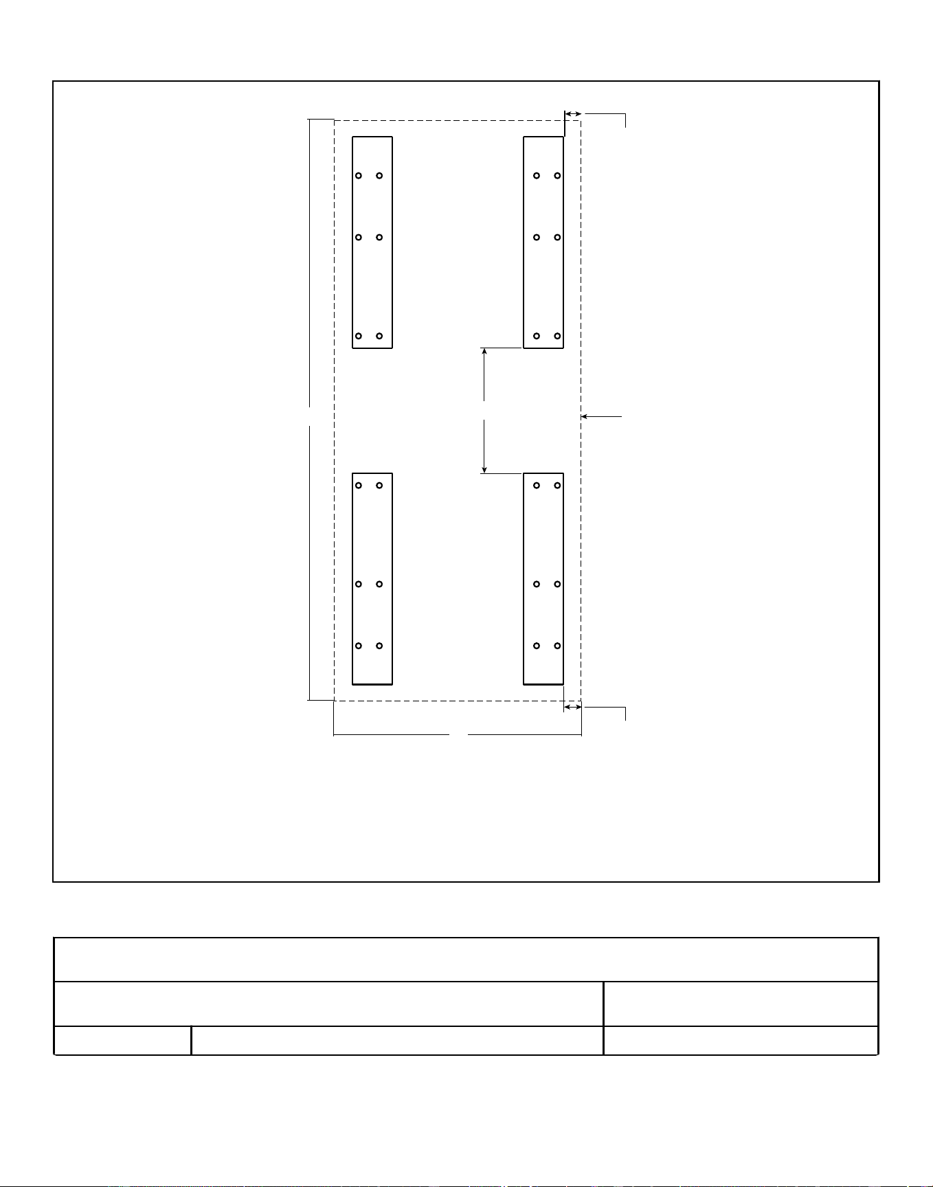
Dimensional Clearances - Back to Back Mount - 80 and 100 Pound [36.3 and 45.4 Kg] Models (refer to Table 17 )
CHM2522N_SVG
C
D
1
2
3
B
B
3
4
1
A
5
1. Front-facing Edge of Pad
2. Machine 2
3. Rear of Machine
4. Machine 1
5. Side Edge of Pad or Wall
Figure 17
Back-to-Back Mount - 80 and 100 Pound [36.3 and 45.4 Kg] Models, in. [mm]
Description 80-100
A Adjacent rear spacing (minimum) 33.3 [846]
Table 17 continues...
Installation
©
Copyright, Alliance Laundry Systems LLC -
DO NOT COPY or TRANSMIT
51 Part No. F8619501ENR4
Downloaded from www.ManualsFile.com manuals search engine
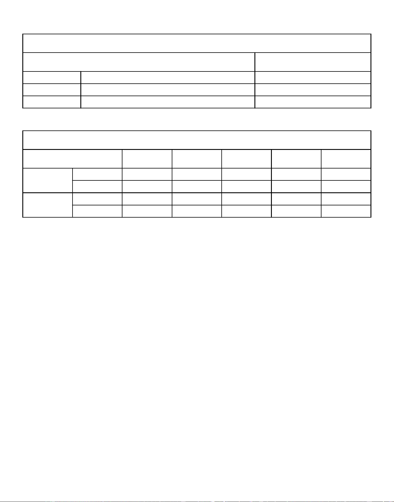
Back-to-Back Mount - 80 and 100 Pound [36.3 and 45.4 Kg] Models, in. [mm]
Description 80-100
B Distance of machine base to edge of pad (minimum) 8 [203]
C Length of pad (minimum) 130.56 [3316]
D Width of pad (minimum) 51.5 [1308]
Table 17
Pad Thickness Requirements, in. [mm]
Specification 20 30 40 60 80-100
Minimum Foun-
dation Thickness
F-speed 4 [102] 4 [102] 4 [102] 4 [102] 6 [152]
V-speed 4 [102] 4 [102] 6 [152] 6 [152] 9 [229]
Minimum Exca-
vation Depth
F-speed 8 [203] 8 [203] 8 [203] 8 [203] 12 [305]
V-speed 8 [203] 8 [203] 12 [305] 12 [305] 15 [381]
Table 18
Installation
©
Copyright, Alliance Laundry Systems LLC -
DO NOT COPY or TRANSMIT
52 Part No. F8619501ENR4
Downloaded from www.ManualsFile.com manuals search engine
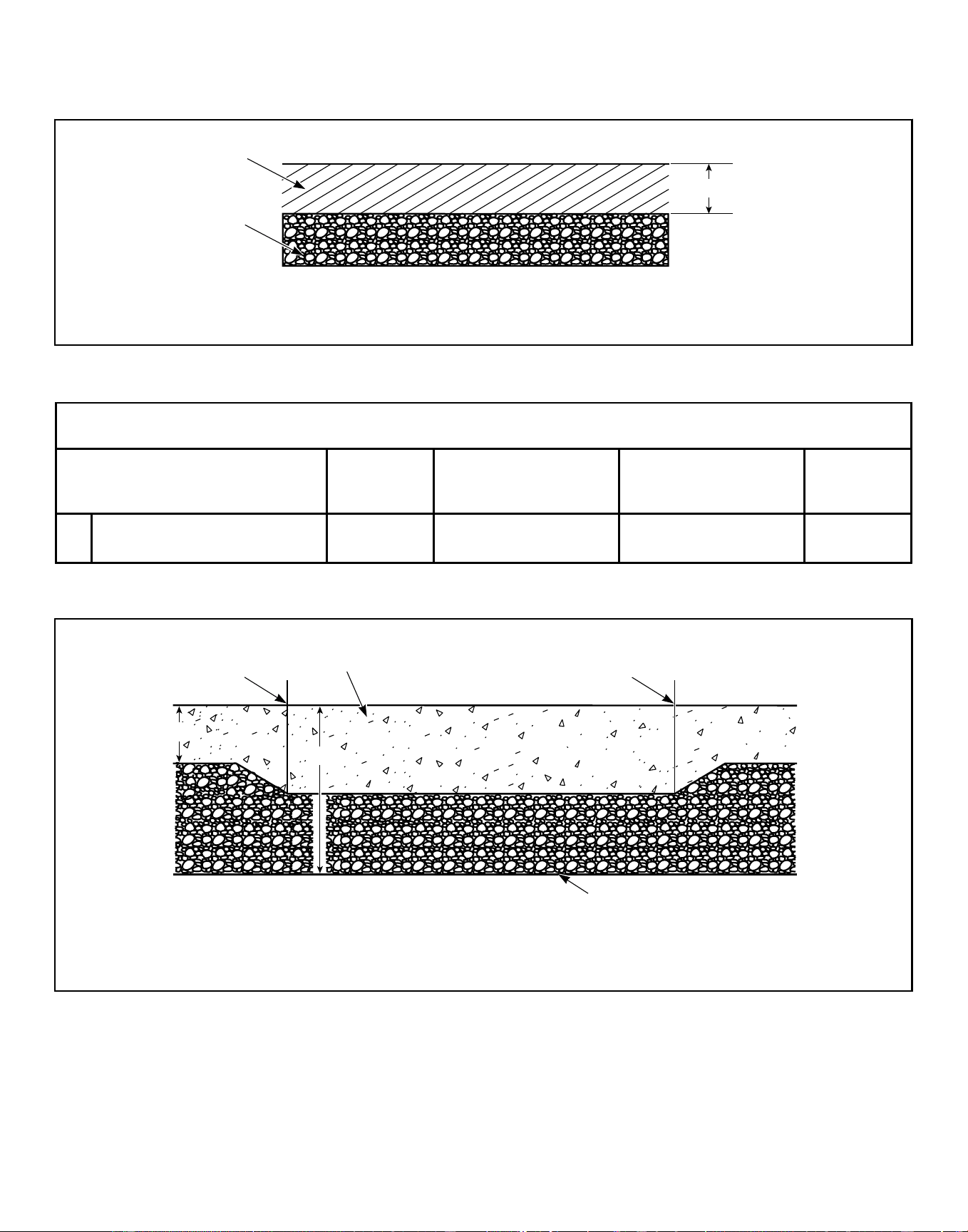
Foundation Requirements
Existing Floor (refer to Table 19 )
PHM814N_SVG
1
A
2
1. Existing Floor with 3500 PSI (minimum) Concrete
2. Compacted Fill (minimum 6 in. [152 mm])
Figure 18
Existing Floor, in. [mm]
Description 20-30 40-60 (F-speed)
40-60 (V-speed) /
80-100 (F-speed)
80-100 (V-
speed)
A Required thickness of existing
floor (minimum)
4 [102] 4 [102] 6 [152] 9 [229]
Table 19
New Monolithic Floor (refer to Table 20 )
PHM981N_SVG
2
3
B
A
1
1
1. Edge of Pad
2. 3500 PSI (minimum) Concrete
3. Compacted Fill (minimum 6 in. [152 mm] beneath machine)
Figure 19
Installation
©
Copyright, Alliance Laundry Systems LLC -
DO NOT COPY or TRANSMIT
53 Part No. F8619501ENR4
Downloaded from www.ManualsFile.com manuals search engine
New Monolithic Floor, in. [mm]
Description 20-30 40-60 (F-speed)
40-60 (V-speed) /
80-100 (F-speed)
80-100 (V-
speed)
A Depth of Surrounding Floor 4 [102] 4 [102] 6 [152] 6 [152]
B Total depth of foundation (con-
crete plus 6 in. [152 mm] fill)
(minimum)
8 [203] 8 [203] 12 [305] 15 [381]
Table 20
Installation
©
Copyright, Alliance Laundry Systems LLC -
DO NOT COPY or TRANSMIT
54 Part No. F8619501ENR4
Downloaded from www.ManualsFile.com manuals search engine
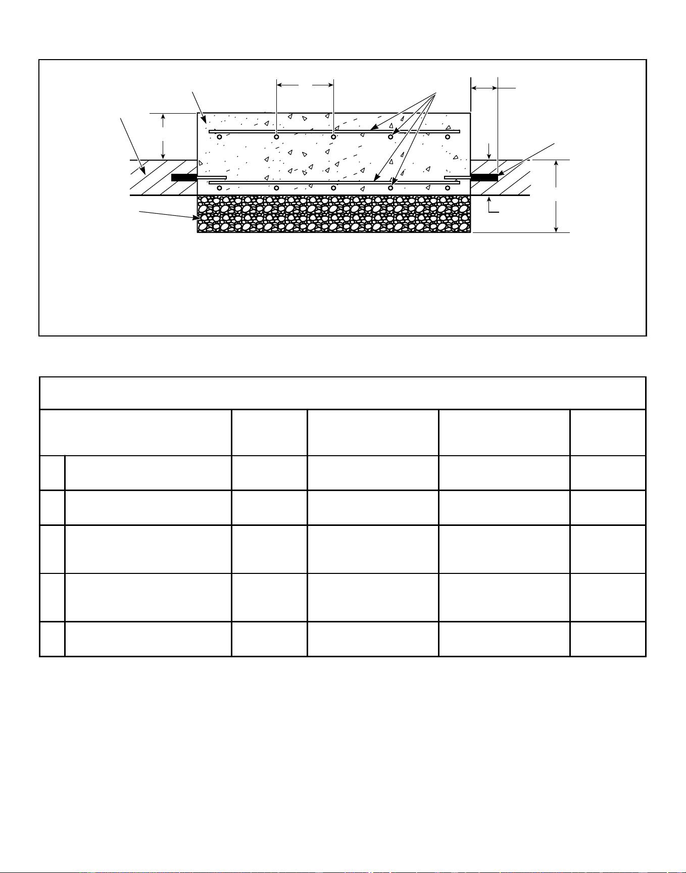
Elevated Pad (refer to Table 21 )
PHM852N_SVG
1
2
3
B
C
E
D
A
4
5
1. Existing Floor
2. 3500 PSI (minimum) Concrete
3. Reinforcing Bar
4. Perimeter Reinforcing Bar
5. Compacted Fill (minimum 6 in. [152 mm])
Figure 20
Elevated Pad, in. [mm]
Description 20-30 40-60 (F-speed)
40-60 (V-speed) /
80-100 (F-speed)
80-100 (V-
speed)
A Height of elevated pad above
floor (maximum)
8 [203] 8 [203] 8 [203] 8 [203]
B Distance between reinforcing
bars (maximum)
12 [305] 12 [305] 12 [305] 12 [305]
C Length of reinforcing bar ex-
tending into existing floor (mini-
mum)
2.5 [64] 2.5 [64] 2.5 [64] 2.5 [64]
D Total depth of foundation (con-
crete plus 6 in. [152 mm] fill)
(minimum)
8 [203] 8 [203] 12 [305] 15 [381]
E Required thickness of existing
floor (minimum)
4 [102] 4 [102] 6 [152] 6 [152]
Table 21
Installation
©
Copyright, Alliance Laundry Systems LLC -
DO NOT COPY or TRANSMIT
55 Part No. F8619501ENR4
Downloaded from www.ManualsFile.com manuals search engine
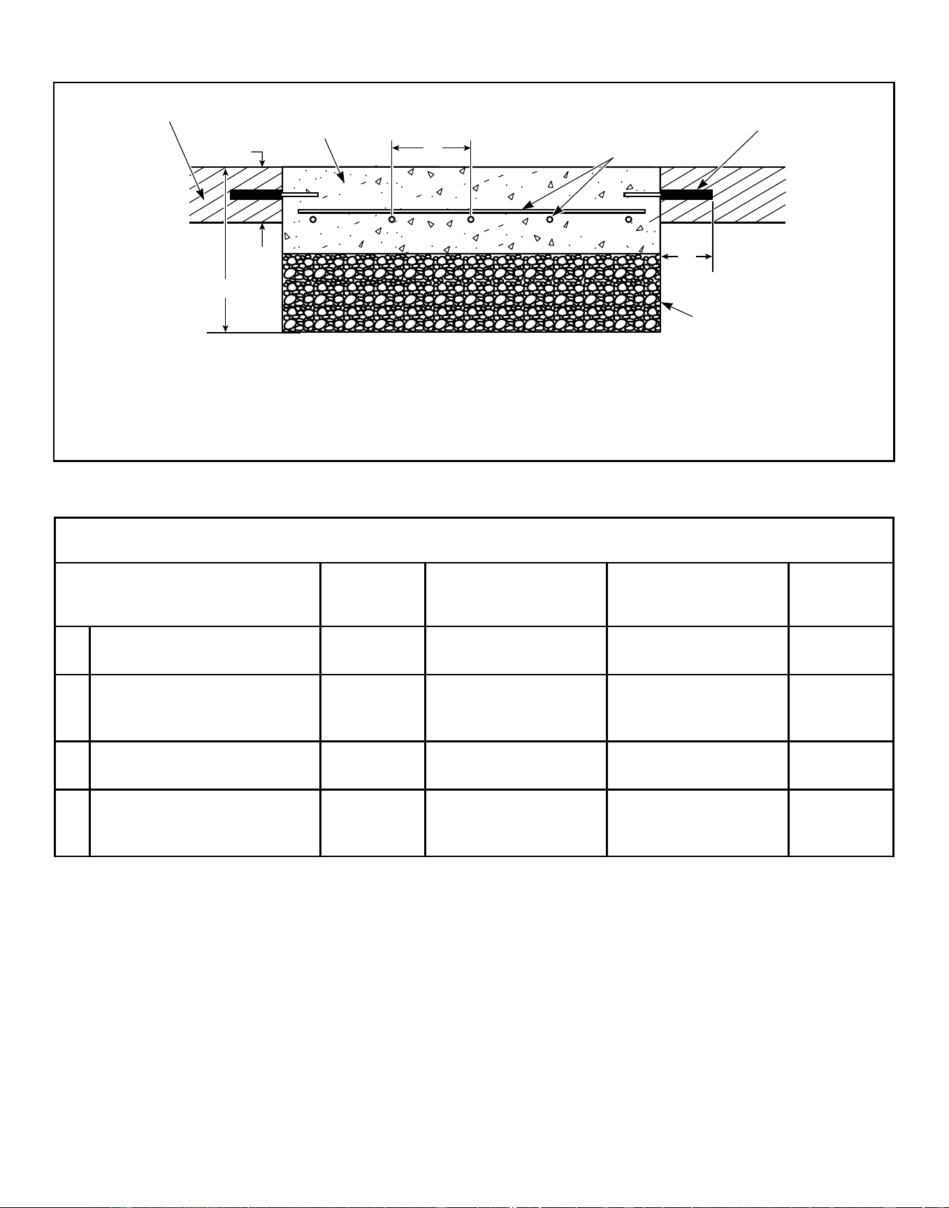
Tie-in to Existing Floor (refer to Table 22 )
CHM2390N_SVG
1
2
B
C
D
A
4
5
3
1. Existing Floor
2. 3500 PSI (minimum) Concrete
3. Reinforcing Bar
4. Perimeter Reinforcing Bar
5. Compacted Fill (minimum 6 in. [152 mm])
Figure 21
Tie-in to Existing Floor, in. [mm]
Description 20-30 40-60 (F-speed)
40-60 (V-speed) /
80-100 (F-speed)
80-100 (V-
speed)
A Required thickness of existing
floor (minimum)
4 [102] 4 [102] 6 [152] 6 [152]
B Total depth of foundation (con-
crete plus 6 in. [152 mm] fill)
(minimum)
8 [203] 8 [203] 12 [305] 15 [381]
C Distance between reinforcing
bars (minimum)
12 [305] 12 [305] 12 [305] 12 [305]
D Length of reinforcing bar ex-
tending into existing floor (mini-
mum)
2.5 [64] 2.5 [64] 2.5 [64] 2.5 [64]
Table 22
Installation
©
Copyright, Alliance Laundry Systems LLC -
DO NOT COPY or TRANSMIT
56 Part No. F8619501ENR4
Downloaded from www.ManualsFile.com manuals search engine
Machine Mounting and Grouting
NOTE: After the concrete has cured completely and the
cast-in-place method was used, refer to Figure 23 and
proceed to Step 7. If acrylic adhesive anchors are de-
sired, refer to Figure 22 and proceed with Step 1 after
concrete has cured completely.
1. Refer to Table 23 to set the drill depth gauge.
2. Drill the holes to the set depth.
3. Use compressed air or squeeze bulb to clean out debris from
each hole.
4. Fill half the hole depth with an industry-accepted adhesive an-
choring system.
5. Insert anchor bolt until it reaches the bottom. Refer to Table
23 .
6. Ensure all air pockets are removed from adhesive surrounding
the bolt.
7. Allow adhesive around bolt to cure completely.
8. Remove shipping materials and place the machine or elevated
base frame carefully over the bolts.
NOTE: Never attempt to lift the machine by the door
handle or by pushing on the cover panels. Always
insert a pry bar or other lifting device under the bot-
tom frame of the machine to move it.
IMPORTANT: DO NOT install 80 models or larger
machines on an elevated metal base frame.
9. Raise and level the machine or elevated base frame 1/2 inch
[1.27 cm] off the floor on four corners, using spacers such as
nut fasteners.
WARNING
Crush hazard. To avoid personal injury and/or
property damage, do not tip the machine more
than 25 degrees in any direction.
W793
10. Completely fill the space between the elevated base frame or
machine base and the floor with a good quality non-shrink-
ing machinery precision grout to ensure a stable installation.
Grout completely under frame. Remove front panel and back
panel to gain access to entire perimeter of base plates. Force
grout under base until all voids are filled.
IMPORTANT: Minimum Grade 5, SAE rating, flat
washers and minimum Grade 5, SAE rating, serrated
hex flange locknuts are the recommended hardware
for anchoring machine or elevated base frame to an-
chor bolts.
11. Position the flat washers and locknuts on the anchor bolts and
finger-tighten to machine base or elevated base frame.
12. Allow machine grout to set, but not cure.
IMPORTANT: Refer to bolt manufacturer’s recom-
mended adhesive cure times.
13. Remove the spacers carefully, allowing the machine base or
elevated base frame to settle into the wet grout.
NOTE: If installing a 20-60 model directly to finished
floor, wait until grout is completely cured and skip
to Step 18. If installing on elevated base frame, pro-
ceed to Step 14.
20-60 Models
14. After the grout is completely cured, position the machine over
the elevated base frame.
15. Align the mounting holes on the machine with the corre-
sponding holes on the elevated base frame.
16. Install a bolt, flat washer and locknut in each mounting hole.
17. Hand tighten each nut.
a. Tighten the two rear nuts two turns.
b. Tighten the two front nuts two turns.
c. Tighten the two middle nuts firmly.
18. Torque all the locknuts to 90 ± 9 ft.-lbs. – one after the other –
until all are tightened evenly and the machine is fastened se-
curely to the elevated base frame or floor.
80 Models and Larger
19. After the grout is completely cured, torque the locknuts to 150
± 15 ft.-lbs. – one after the other – until all are tightened even-
ly and the machine is fastened securely to the floor.
IMPORTANT: Refer to recommended grout cure
times from manufacturer before torquing locknuts.
IMPORTANT: All torque joints must remain dry (non-
lubricated).
NOTE: Check and retighten the locknuts after five to
ten days of operation and every month thereafter.
Installation
©
Copyright, Alliance Laundry Systems LLC -
DO NOT COPY or TRANSMIT
57 Part No. F8619501ENR4
Downloaded from www.ManualsFile.com manuals search engine
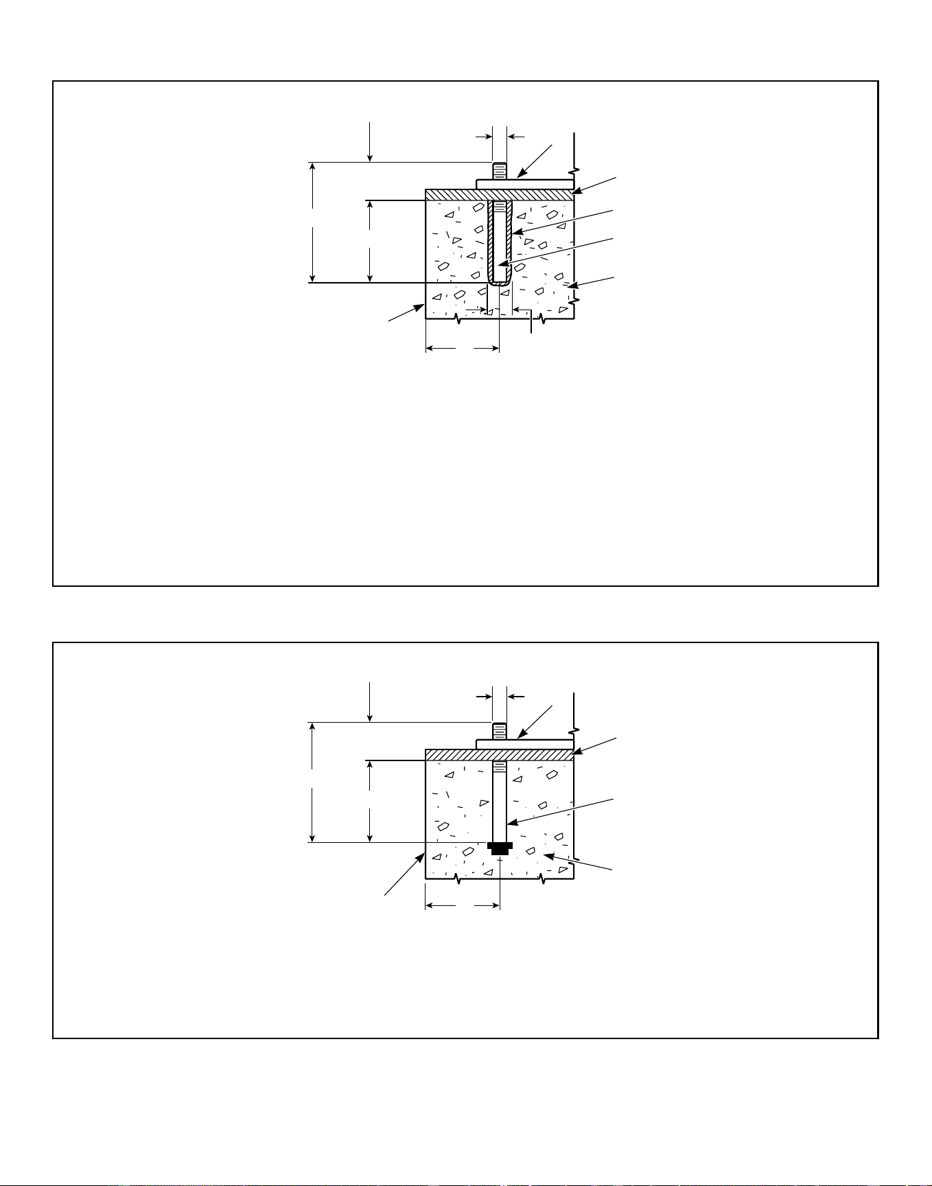
Acrylic Adhesive Anchors (refer to Table 23 )
PHM811N_SVG
7
A
D
E
B
C
1
6
2
5
3
4
NOTE: *Available for purchase through the distributor. If not purchasing from a distributor, procure acrylic ad-
hesive rated for commercial-grade vibratory machine installations.
1. Machine Frame Base
2. Grout 1/2 in. [13 mm]
3. Acrylic Adhesive*
4. Anchor Bolt* (minimum Grade 5 SAE rating)
5. Concrete
6. Drill Hole Size per Manufacturer Requirements
7. Edge of Pad
Figure 22
Cast-in-place Anchors (refer to Table 23 )
CHM2438N_SVG
5
A
D
E
B
C
1
2
4
3
1. Machine Frame Base
2. Grout
3. Anchor Bolt (minimum Grade 5 SAE rating)
4. Concrete
5. Edge of Pad
Figure 23
Installation
©
Copyright, Alliance Laundry Systems LLC -
DO NOT COPY or TRANSMIT
58 Part No. F8619501ENR4
Downloaded from www.ManualsFile.com manuals search engine
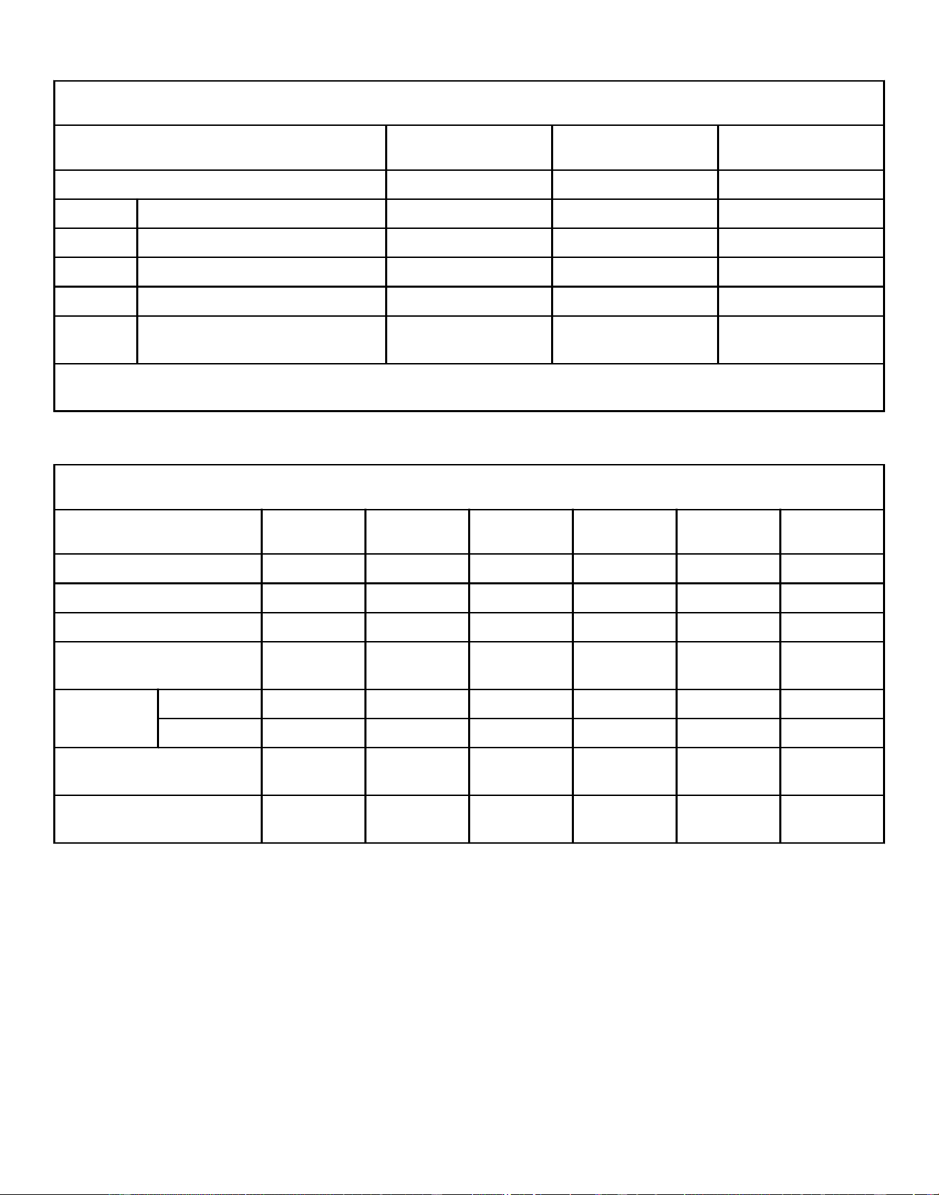
Minimum Anchoring Specifications, in. [mm]
Description 20-40 60 80-100
Number of Bolts 4 or 6* 6 6
A Bolt Length 6 [152] 6 [152] 8-3/4 [216]
B Thread Extension 2-1/2 [64] 2-1/2 [64] 2-3/4 [70]
C Bolt Diameter 5/8 [16] 5/8 [16] 3/4 [19]
D Embedment Depth 3-1/2 [89] 3-1/2 [89] 6 [152]
E Distance from Bolt Center to Edge of
Concrete Pad
Refer to Table 2 Refer to Table 2 Refer to Table 2
* On 20-40 models, the four (4) corner bolts are required and the two (2) center bolts are optional when mounting a machine or
elevated base frame to floor.
Table 23
Floor Load Data
Specification 20 30 40 60 80 100
Static floor load, lbs. [kN] 430 [1.91] 550 [2.45] 690 [3.07] 920 [4.09] 1590 [7.07] 1690 [7.51]
Static pressure, lbs.-ft
2
[kN-m
2
] 97 [4.64] 95 [4.55] 98 [4.69] 105 [5.03] 140 [6.70] 149 [7.13]
Dynamic floor load, lbs. [kN] 420 [1.86] 630 [2.80] 840 [3.74] 1260 [5.61] 1680 [7.48] 1680 [7.48]
Dynamic floor pressure, lbs.-
ft2 [kN-m
2
]
96 [4.60] 109 [5.22] 119 [5.70] 143 [6.85] 149 [7.13] 149 [7.13]
Dynamic load
frequency, Hz
F-speed 9.7 9.0 8.6 8.1 7.4 7.4
V-speed 13.7 12.8 12.2 11.4 10.4 9.5
Maximum moment about ma-
chine base, lbs.-ft. [kN-m]
805 [1.09] 1260 [1.71] 1820 [2.47] 2770 [3.76] 4330 [5.87] 4330 [5.87]
Maximum vertical load, lbs.
[kN]
800 [3.56] 1130 [5.03] 1460 [6.49] 2060 [9.16] 3090 [13.75] 3160 [14.06]
Table 24
Installation
©
Copyright, Alliance Laundry Systems LLC -
DO NOT COPY or TRANSMIT
59 Part No. F8619501ENR4
Downloaded from www.ManualsFile.com manuals search engine
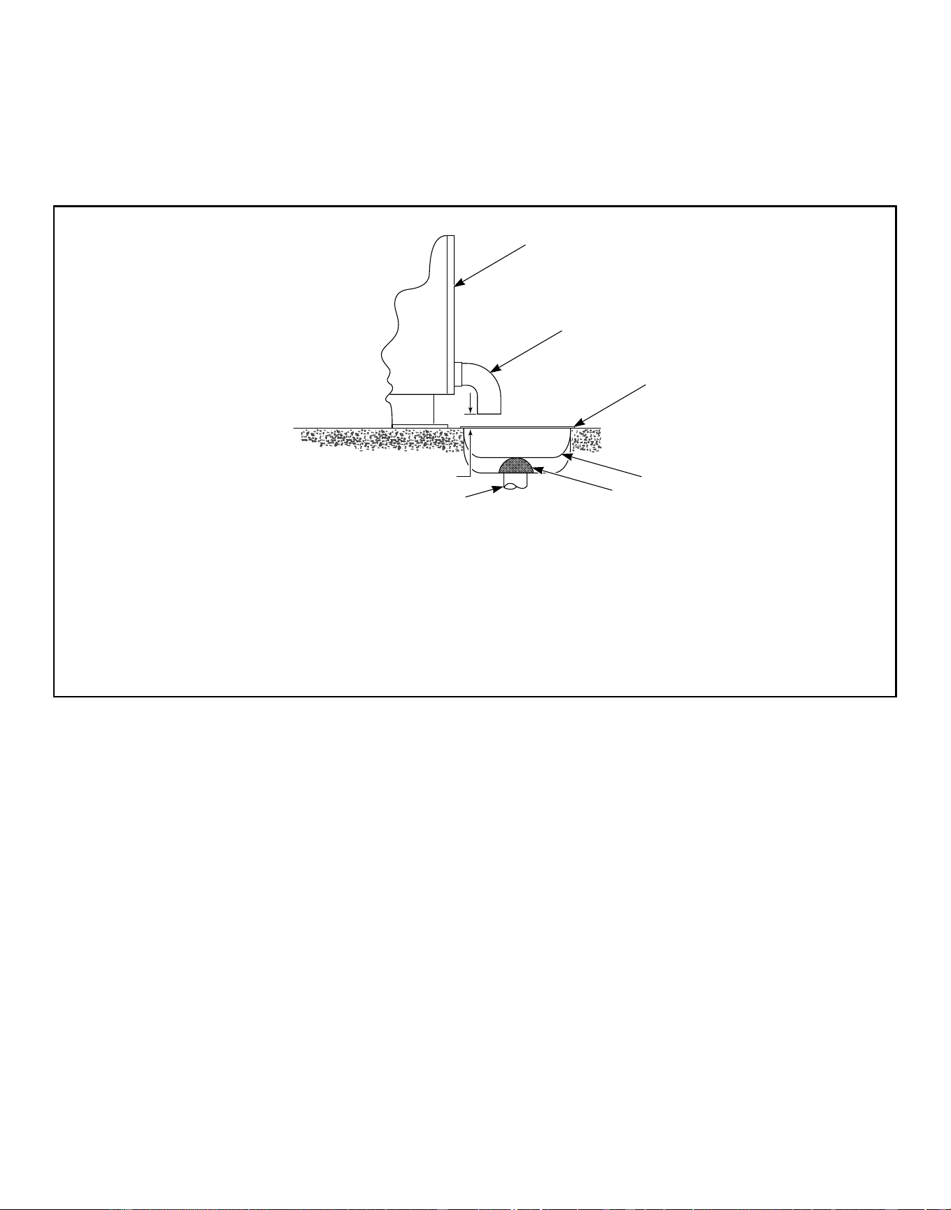
Drain Connection Requirements
IMPORTANT: Machine must be installed in accordance
with all local codes and ordinances.
All drain systems must be vented to prevent an air lock or siphon-
ing.
Use the supplied black rubber adapter and clamps to transition
from the machine drain outlet to the 3 inches [76 mm]schedule
40 PVC plumbing.
If proper drain size is not available or practical, a surge tank is
required. A surge tank along with a sump pump should be used
when gravity drainage is not possible.
Drain Trough System
CHM2379N_SVG
1
2
3
4
5
6
7
1. Rear of Machine
2. Drain Pipe
3. Steel Grate
4. Drain Trough
5. Strainer
6. Waste Line
7. 1 in. [25 mm] minimum gap
Figure 24
Installation
©
Copyright, Alliance Laundry Systems LLC -
DO NOT COPY or TRANSMIT
60 Part No. F8619501ENR4
Downloaded from www.ManualsFile.com manuals search engine
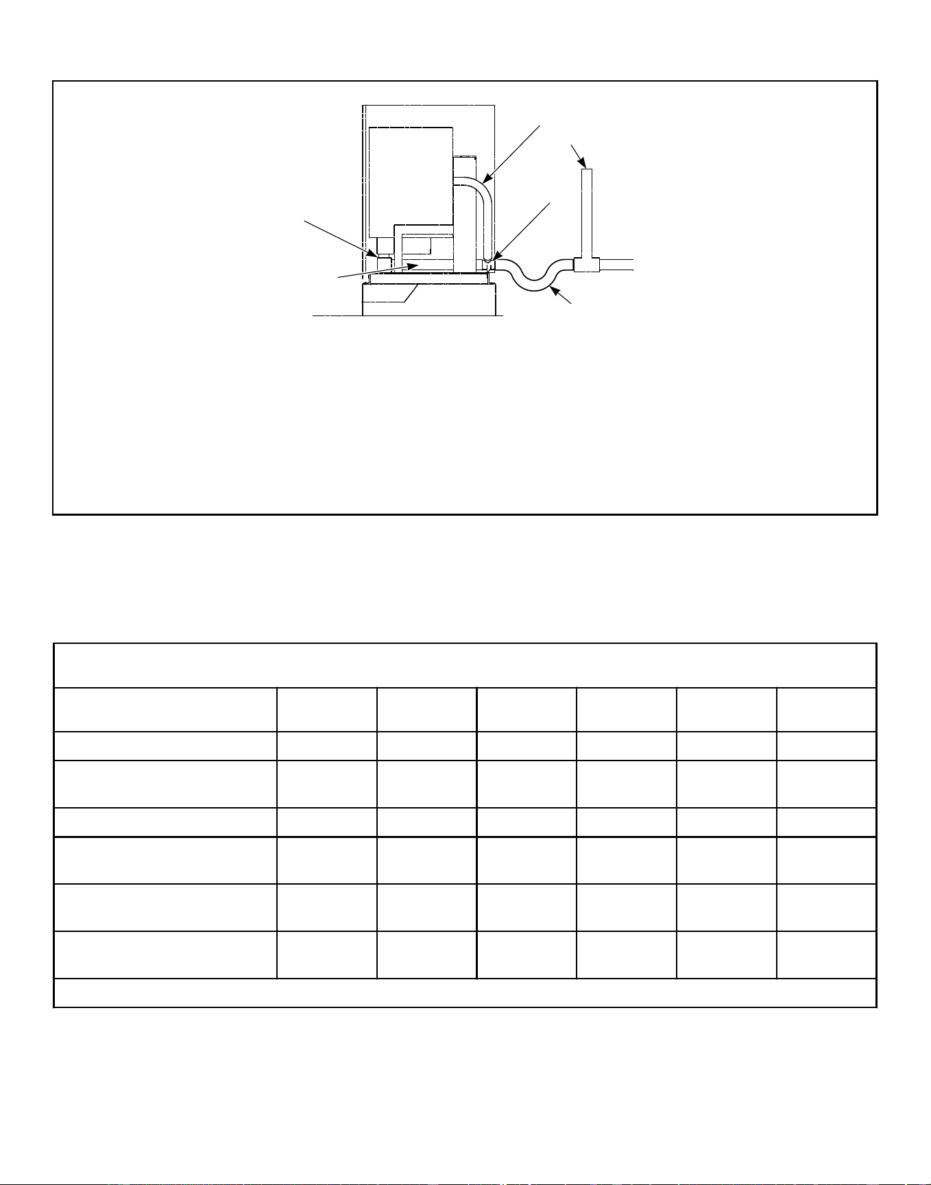
Direct Drain System
CHM2386N_SVG
6
5*
3
4
2
1
* Drain line must be vented to meet local plumbing codes.
1. Drain Hose
2. Drain Valve
3. Drain Tee
4. Overflow Hose
5. Vent Pipe*
6. Trap (as required by local codes)
Figure 25
IMPORTANT: Increasing the drain hose length, instal-
ling elbows, or causing bends will decrease drain flow
rates and increase drain times, impairing machine per-
formance.
Drain Information
Specification 20 30 40 60 80 100
Drain connection size, in. 3* 3* 3* 3* 3* 3*
Overflow drain connection size,
in.
1-1/2 2-1/4 2-1/4 2-1/4 2-1/4 2-1/4
Number of drain outlets 1 1 1 1 1 1
Drain flow capacity, gal/min
[l/min]
25 [95] 30 [114] 40 [151] 50 [189] 55 [208] 55 [208]
Maximum discharge (level 30),
gal [l]
11.2 23.9 27.4 30.8 43.4 53.3
Recommended drain pit size, ft
3
[l]
2.0 [57] 2.5 [71] 3.5 [128] 5.7 [161] 8.0 [221] 9.5 [269]
* Also works with 3 inch OD PVC pipe if connected to inside of drain tee connector.
Table 25
Installation
©
Copyright, Alliance Laundry Systems LLC -
DO NOT COPY or TRANSMIT
61 Part No. F8619501ENR4
Downloaded from www.ManualsFile.com manuals search engine
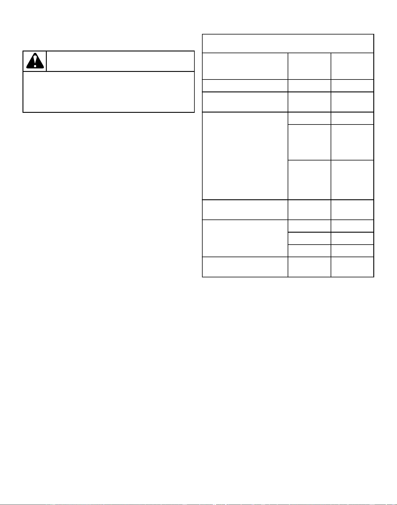
Water Connection Requirements
WARNING
To prevent personal injury, avoid contact with inlet
water temperatures higher than 125° Fahrenheit [51°
Celsius] and hot surfaces.
W748
The maximum water inlet temperature for vended models is
125°F [51°C]and the recommended maximum water inlet tem-
perature for on-premises models is 150°F [66°C] (standard mod-
els) or 140°F [60°C] (WRAS approved models) .
Connections should be supplied by a hot and a cold water line of
at least the sizes shown in Water Supply Line Sizing . Installation
of additional machines will require proportionately larger water
lines.
Connections should be supplied by a hot and a cold water line per
national and local codes and in accordance with AS/NZS 3500.I.
Water Supply Information
Specification Model
Require-
ment
Water inlet connection size, in. 20-100 3/4
Thread pitch, GHT [BSPP] 20-100 3/4 x 11-1/2
[3/4 x 14]
Number of water inlets 20-40 2
60-100
(standard
models)
4
60-100
(WRAS- ap-
proved mod-
els)
2
Recommended pressure, psi
[kPa]
20-100 30-85
[200-570]
Maximum inlet flow capacity
per machine, gal/min at 85 psi
[l/min at 1232 Pa]
20-40 10.5 [40]
60 18.5 [70]
80-100 23.0 [87]
Extra water inlet flow, gal/min
at 85 psi [l/min at 1232 Pa]
20-100 5.2 [20]
Table 26
Installation
©
Copyright, Alliance Laundry Systems LLC -
DO NOT COPY or TRANSMIT
62 Part No. F8619501ENR4
Downloaded from www.ManualsFile.com manuals search engine
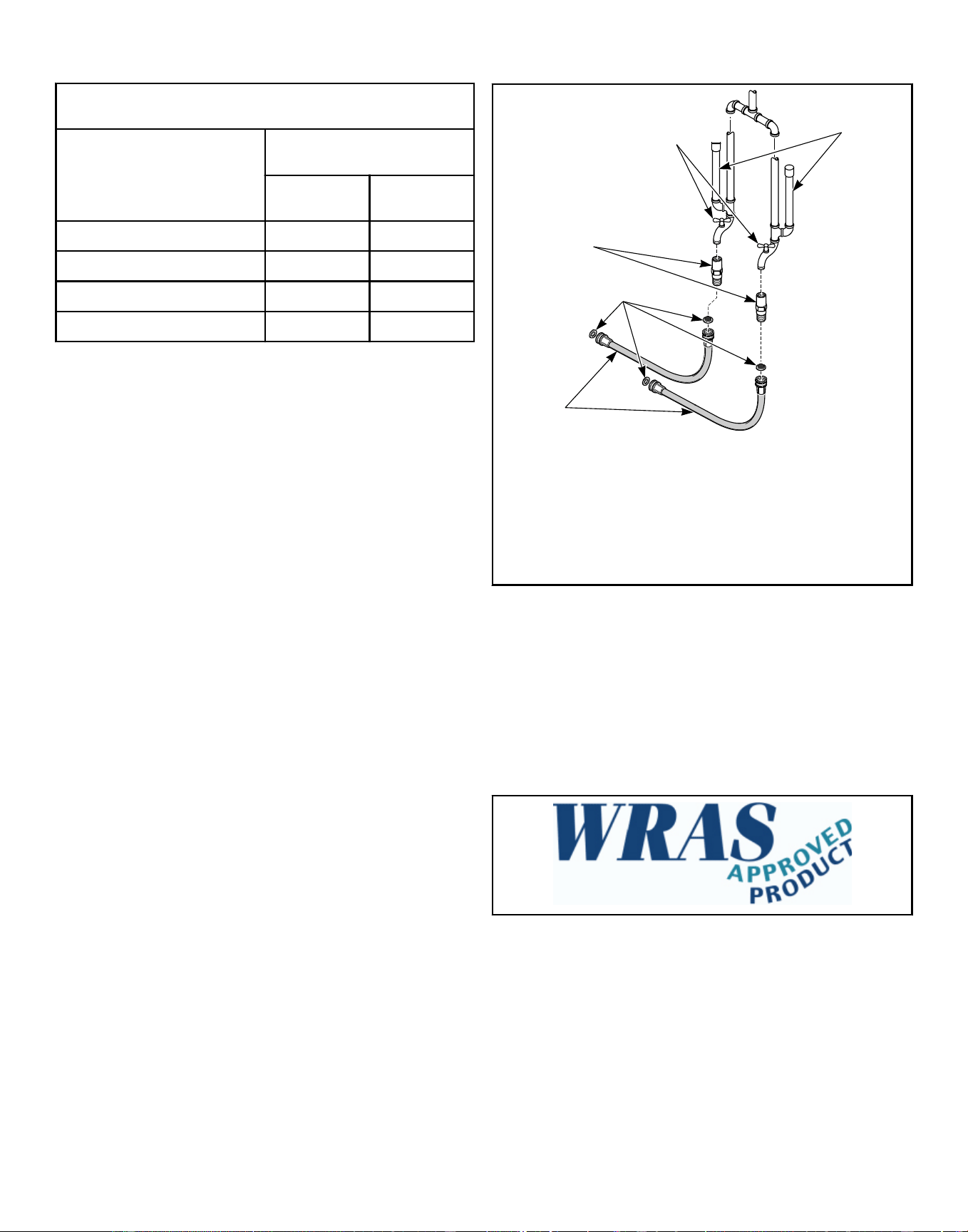
Water Supply Line Sizing, in.
Number of Machines
Supply Line Size
Main Hot/Cold
1 3/4 3/4
2 1 3/4
3 1-1/4 1
4 1-1/2 1
Table 27
Suitable air cushions (risers) should be installed in supply lines to
prevent “hammering.” Refer to Figure 26 .
Alliance Laundry Systems, LLC ranges of front loading commer-
cial clothes washing machines have solenoid valves at the inlets.
The water supply to the washing machines is supplied with an
AB air gap between the soap tray and the drum. Minimum and
maximum working pressure 1.4 bar and 8.3 bar. The machines
are supplied with approved inlet hoses with a maximum inlet di-
mension of 1/2 inch (ID).
NOTE: This machine has a fluid category 5 backflow
prevention device built in between the soap tray and
drum.
PHM831N_SVG
4
5
3
2
1
1. Air Cushions (Risers)
2. Water Supply Faucets
3. Dual Check Valves
4. Filters
5. Hoses
Figure 26
To comply with WRAS (IRN R150) and Australian water regula-
tions, European standard EN1717 and Australian standard
ATS5200.101, an approved dual check valve backflow preven-
tion device with the watermark is provided with the unit and must
be fitted at the point of connection(s) between the supply and the
fitting. Refer to Figure 26 .
NOTE: No more than three (3) water connection hoses
should be used on WRAS-approved models.
Figure 27
Installation
©
Copyright, Alliance Laundry Systems LLC -
DO NOT COPY or TRANSMIT
63 Part No. F8619501ENR4
Downloaded from www.ManualsFile.com manuals search engine
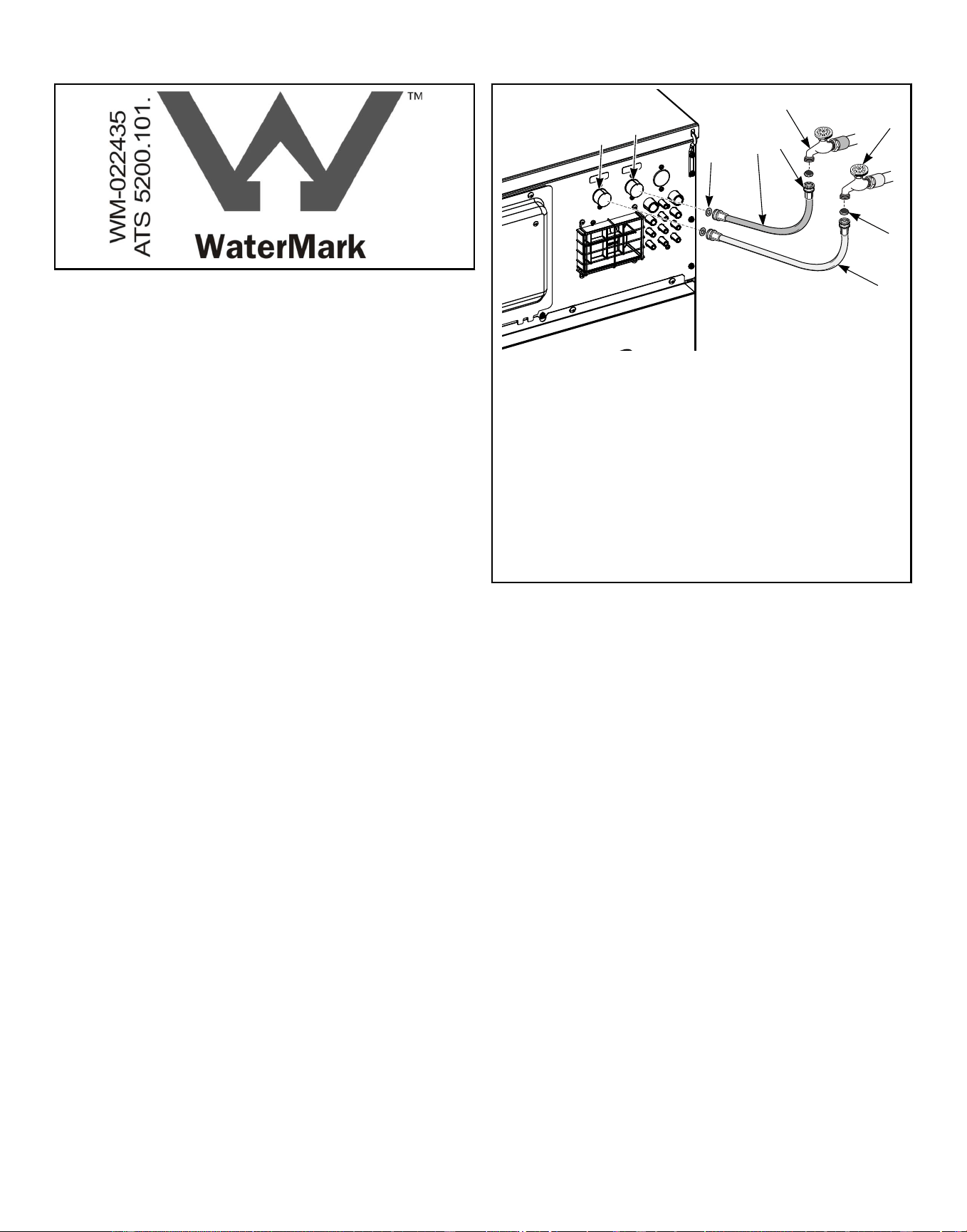
Figure 28
Connect Inlet Hoses (20-40 Models)
To connect water service to a machine with hoses, use the follow-
ing procedure:
1. Before installing hoses, flush the building’s water system at
the machine connection valves for at least two (2) minutes.
2. Remove the two (2) plain rubber washers and two (2) filter
screens from the accessories bag supplied with the machine.
3. Install one (1) plain rubber washer onto one end and one (1)
filter screen into the other end of each fill hose. The screens
must be facing outward toward the water supply. Refer to Fig-
ure 29 .
4. Screw hose couplings with the filter screens onto the water
supply faucets until they are finger-tight. Use the red color-
coded hose for the hot water connection and the blue color-
coded hose for the cold water connection.
5. Using pliers, screw approximately 1/4 turn.
6. Screw the coupling with the plain rubber washer of the red
color-coded hose (attached to the hot water connection) onto
the valve inlet marked with a red label. Screw the coupling
with the plain rubber washer of the blue color-coded hose (at-
tached to the cold water connection) to the valve inlet marked
with a blue label. Tighten to finger-tight.
7. Using pliers, screw approximately 1/4 turn.
IMPORTANT: DO NOT cross thread or overtighten
couplings. This will cause them to leak.
8. Hang hoses in a large loop; do not allow them to kink.
9. Turn on water supply and check for leaks.
10. If leaks are found, turn off the water, unscrew hoses and rein-
stall them until there are no leaks.
IMPORTANT: Turn off water supply whenever there
will be an extended period of non-use.
If additional hose lengths are needed or using hoses other than
those supplied by manufacturer, flexible hoses with screen filters
are required.
8
3
4
9
5
6
7
2
1
CHM2645N_SVG1
1. Cold Water Valve Inlet
2. Hot Water Valve Inlet
3. Rubber Washer (plain)
4. Red Fill Hose (hot)
5. Hose Coupling
6. Hot Water Supply Faucet
7. Cold Water Supply Faucet
8. Filter Screen (screen must be facing outward, toward water
supply)
9. Blue Fill Hose (cold)
Figure 29
Installation
©
Copyright, Alliance Laundry Systems LLC -
DO NOT COPY or TRANSMIT
64 Part No. F8619501ENR4
Downloaded from www.ManualsFile.com manuals search engine
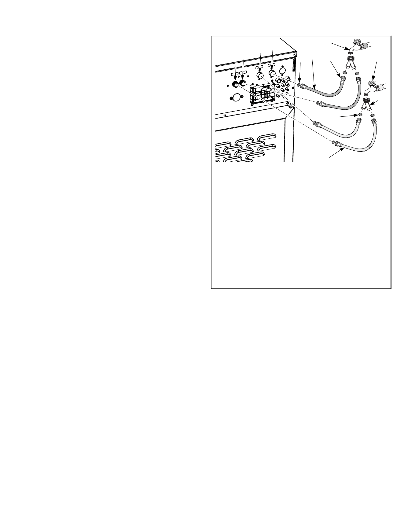
Connect Inlet Hoses with Y-Connectors (60-100
Models)
To connect water service (for laundries with two [2] supply fau-
cets) to a machine with hoses, use the following procedure:
1. Before installing hoses, flush the building’s water system at
the machine connection valves for at least two (2) minutes.
2. Remove the four (4) plain rubber washers and four (4) filter
screens from the accessories bag supplied with the machine.
3. Install one (1) plain rubber washer onto one end and one (1)
filter screen into the other end of each fill hose. The screens
must be facing outward toward the water supply. Refer to Fig-
ure 30 .
4. Screw one (1) of the Y-connectors (supplied with the ma-
chine) into the cold water supply faucet and one (1) into the
hot water supply faucet.
5. Screw hose couplings with the filter screens onto the water
supply faucets until they are finger-tight. Use the two (2) red
color-coded hose for the hot water connection and the two (2)
blue color-coded hose for the cold water connection.
6. Using pliers, screw approximately 1/4 turn.
7. Screw the coupling with the plain rubber washer of one (1) of
the red color-coded hoses (attached to the hot water connec-
tion) onto the main fill valve inlet (marked with a red label).
Screw the coupling with the plain rubber washer of the other
red color-coded hose onto the tub fill valve inlet (marked with
a red label). Tighten to finger-tight. Refer to Figure 30 .
8. Screw the coupling with the plain rubber washer of one (1) of
the blue color-coded hoses (attached to the cold water connec-
tion) onto the main fill valve inlet (marked with a blue label).
Screw the coupling with the plain rubber washer of the other
blue color-coded hose onto the tub fill valve inlet (marked
with a blue label). Tighten to finger-tight. Refer to Figure 30 .
9. Using pliers, screw approximately 1/4 turn.
IMPORTANT: DO NOT cross thread or overtighten
couplings. This will cause them to leak.
10. Hang hoses in a large loop; do not allow them to kink.
11. Turn on water supply and check for leaks.
12. If leaks are found, turn off the water, unscrew hoses and rein-
stall them until there are no leaks.
IMPORTANT: Turn off water supply whenever there
will be an extended period of non-use.
If additional hose lengths are needed or using hoses other than
those supplied by manufacturer, flexible hoses with screen filters
are required.
5
6
7
8
9
CHM2644N_SVG1
12
11
4
3
2
1
10
1. Cold Tub Fill Valve Inlet
2. Hot Tub Fill Valve Inlet
3. Cold Water Main Fill
4. Hot Water Main Fill
5. Rubber Washer (plain)
6. Red Fill Hose (hot)
7. Hose Coupling
8. Hot Water Supply Faucet
9. Cold Water Supply Faucet
10. Y-connection
11. Filter Screen (screen must be facing outward, toward water
supply)
12. Blue Fill Hose (cold)
Figure 30
Installation
©
Copyright, Alliance Laundry Systems LLC -
DO NOT COPY or TRANSMIT
65 Part No. F8619501ENR4
Downloaded from www.ManualsFile.com manuals search engine
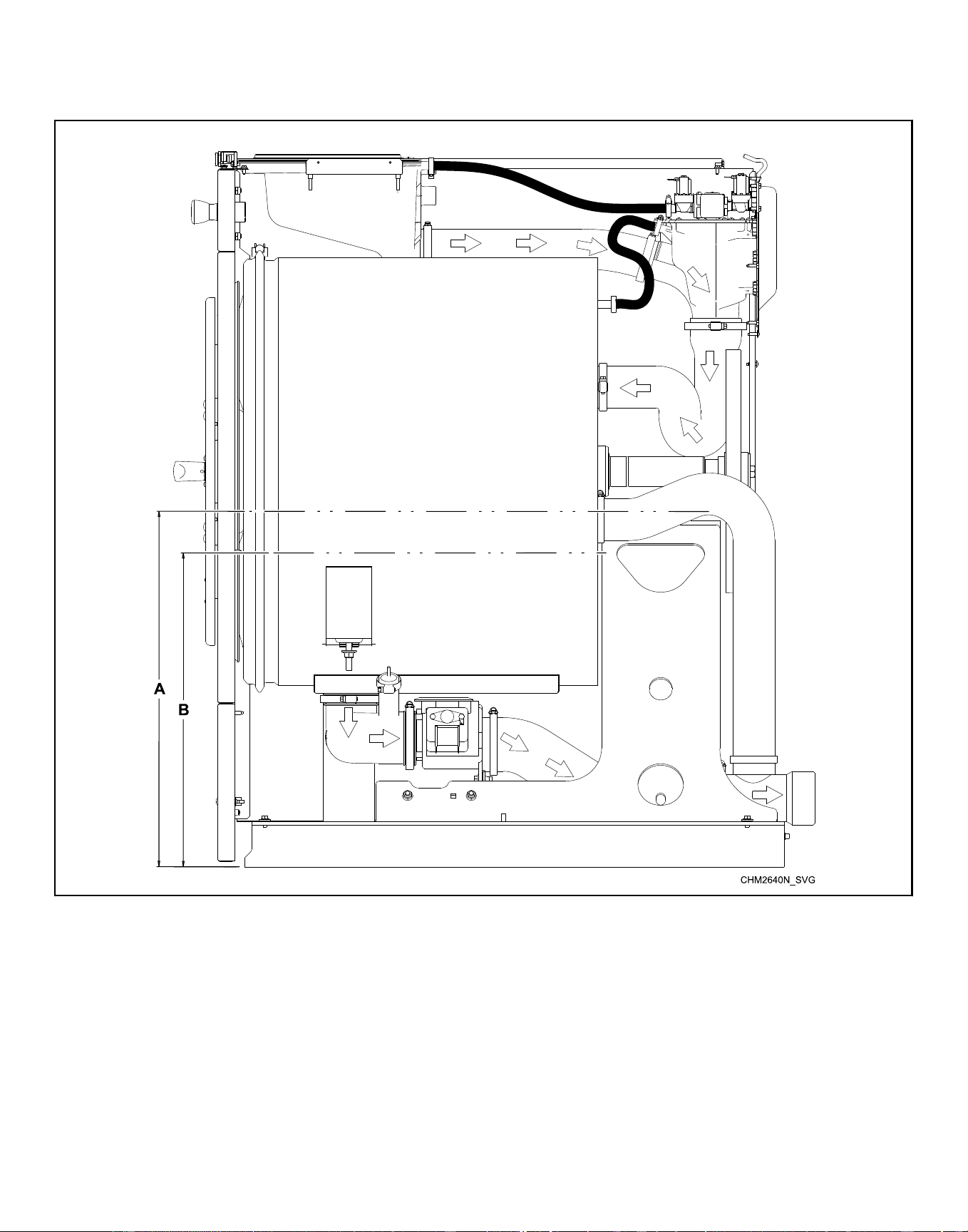
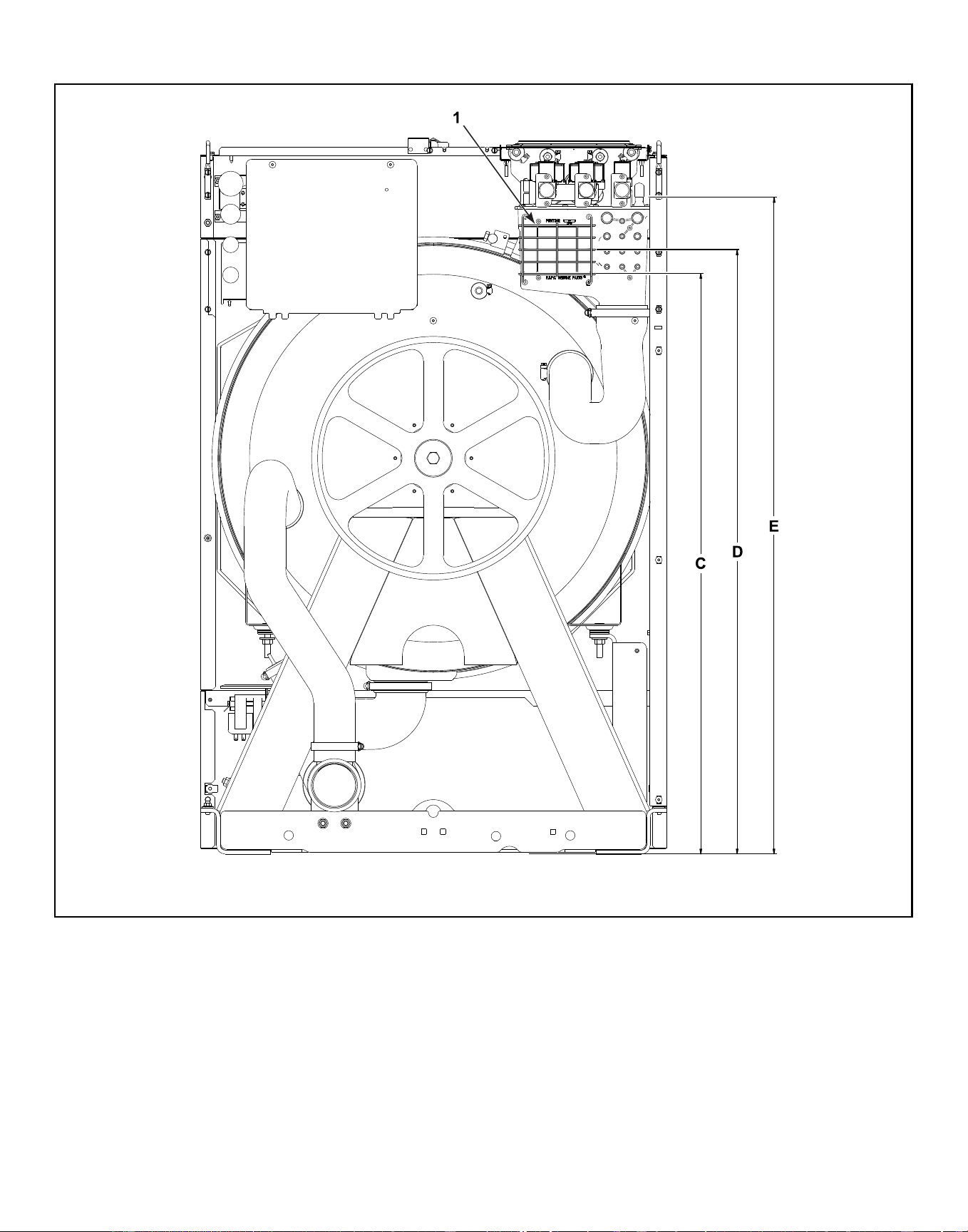
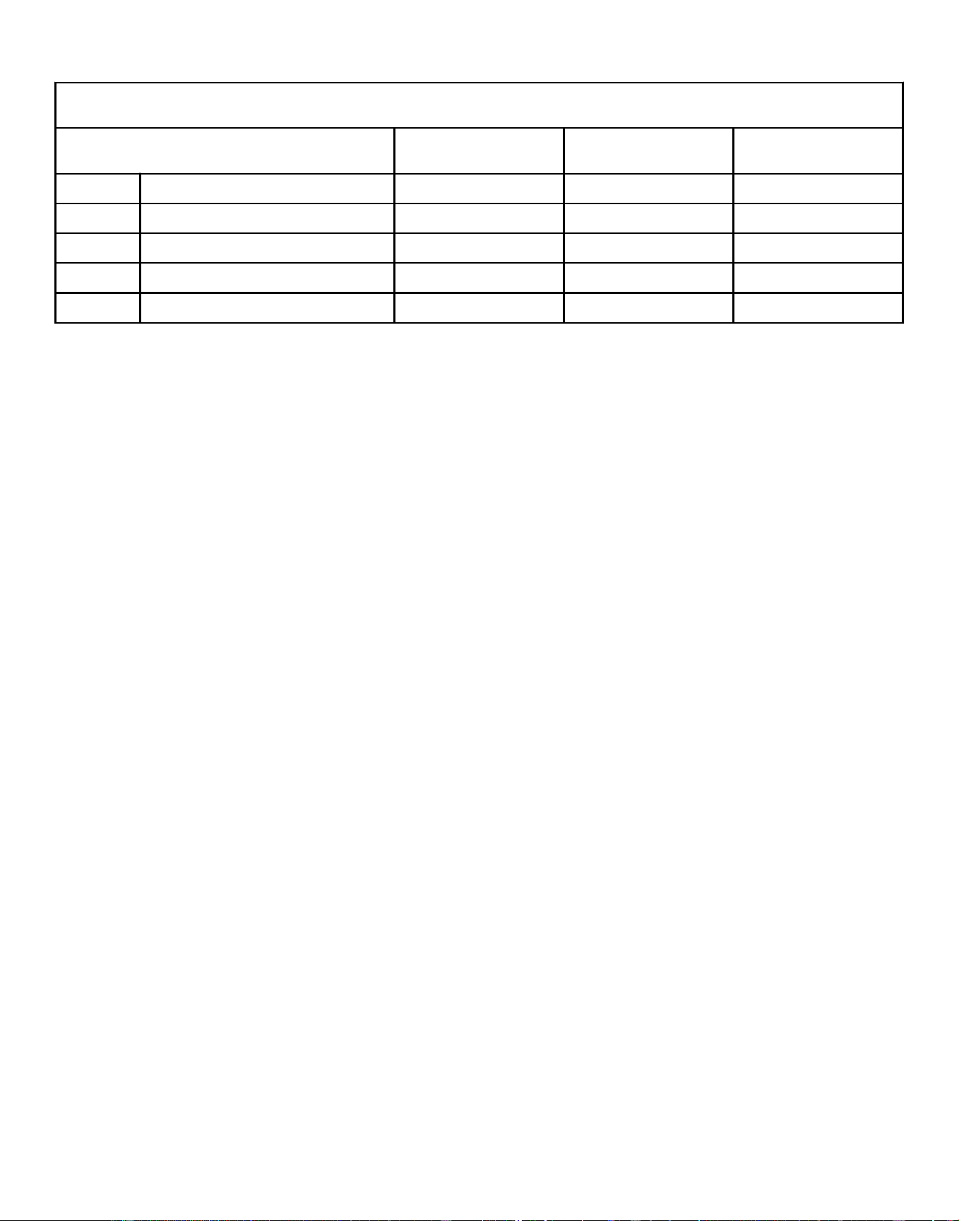
Plumbing Diagram - 20-60 Models, in. [mm]
Description 20 30 40
A Maximum overflow height 20.5 [521] 21.4 [544] 23.1 [587]
B Maximum operating water level 18.5 [470] 17.0 [432] 19.9 [505]
C Vaccum breaker overflow 33.9 [861] 35.8 [909] 38.0 [965]
D Vaccum breaker overflow centerline 35.5 [902] 37.5 [953] 39.7 [1008]
E Inlet Valves 38.9 [988] 41.4 [1052] 43.2 [1097]
Table 28
Installation
©
Copyright, Alliance Laundry Systems LLC -
DO NOT COPY or TRANSMIT
68 Part No. F8619501ENR4
Downloaded from www.ManualsFile.com manuals search engine
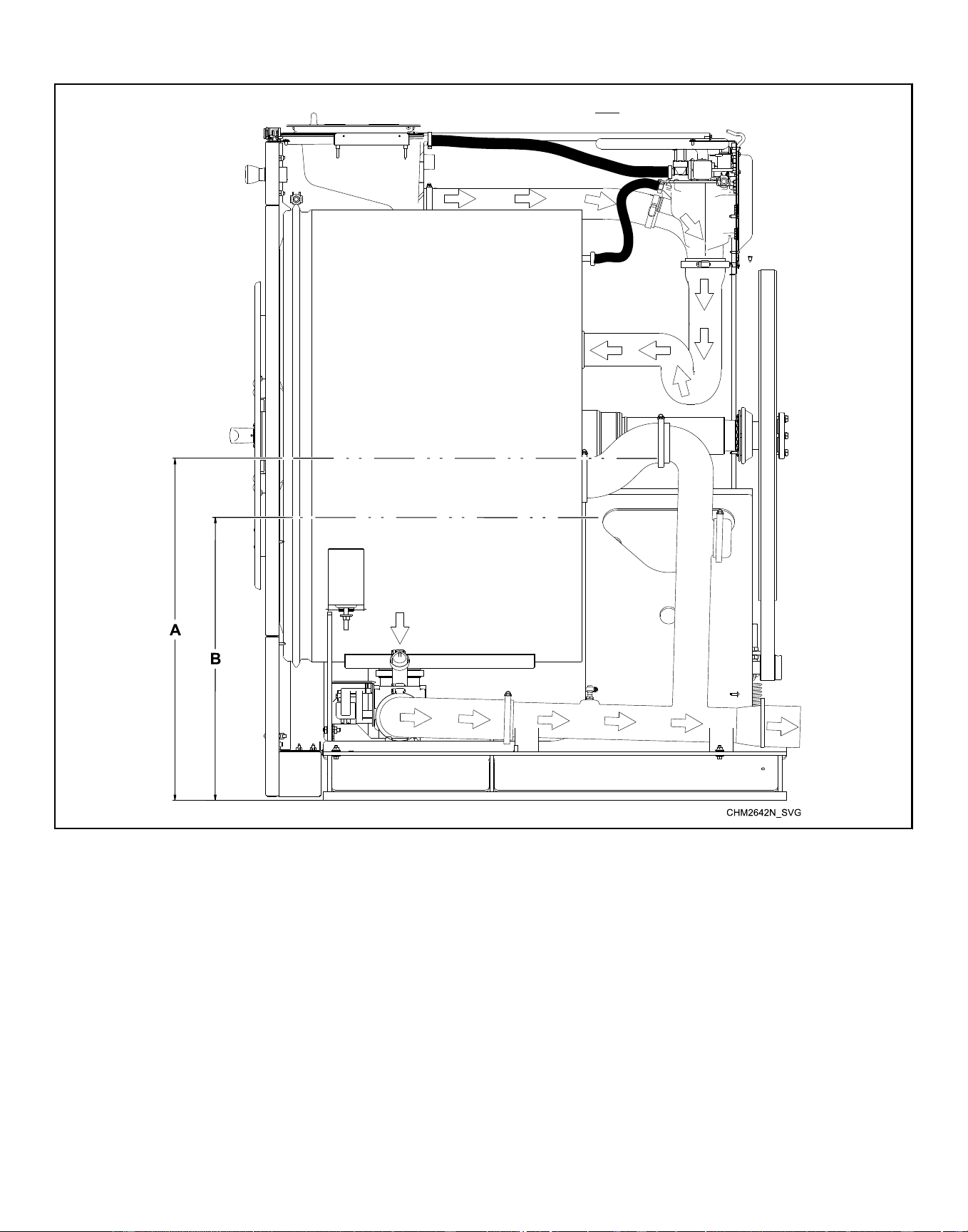
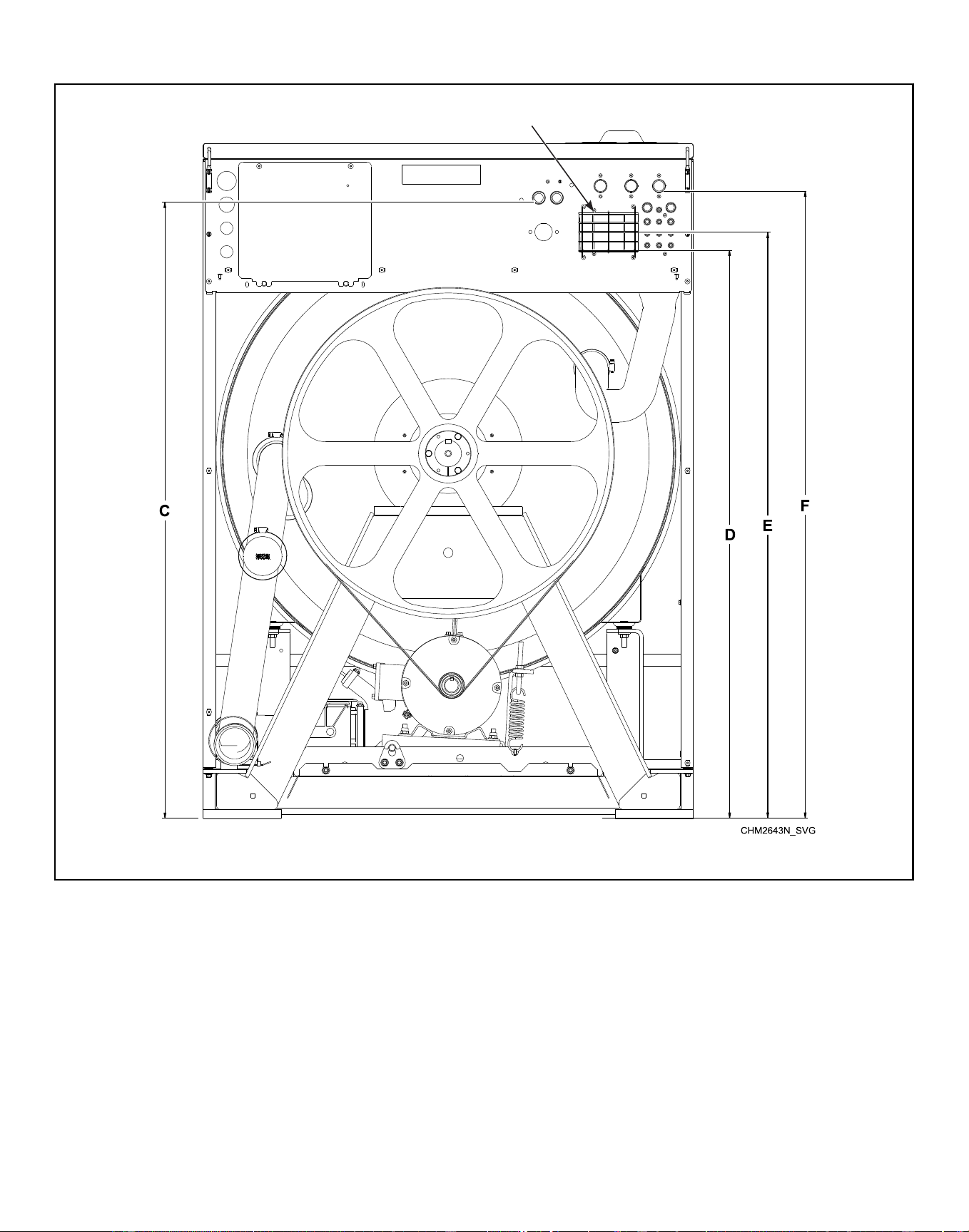
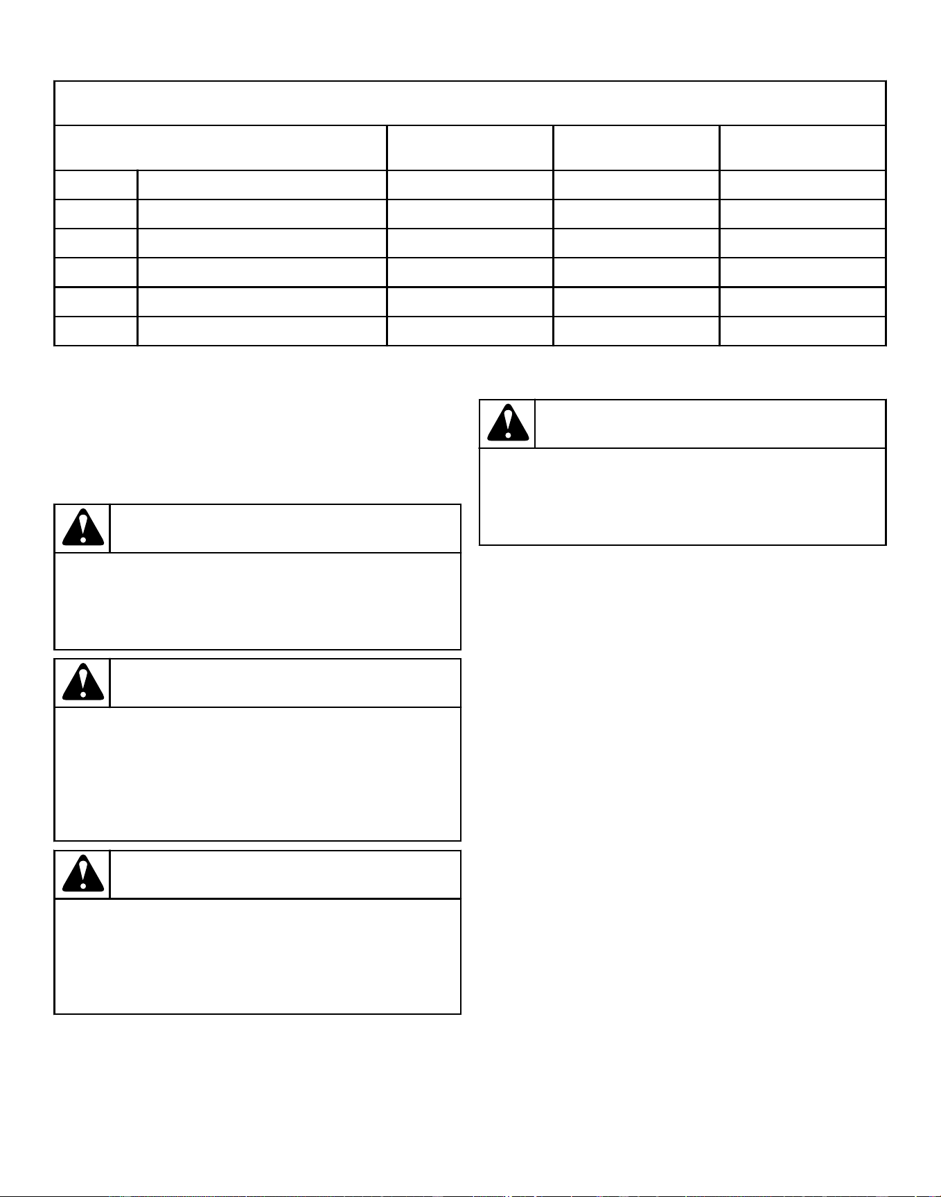
Plumbing Diagram - 60-100 Models, in. [mm]
Description 60 80 100
A Maximum overflow height 23.1 [587] 28.8 [732] 28.8 [732]
B Maximum operating water level 20.6 [523] 24.9 [632] 24.9 [632]
C Aux Inlet valves 45.8 [1163] 52.2 [1326] 52.2 [1326]
D Vaccum breaker overflow 40.7 [1034] 48.0 [1219] 48.0 [1219]
E Vaccum breaker overflow centerline 42.4 [1077] 49.7 [1262] 49.7 [1262]
F Inlet Valves 45.9 [1166] 53.1 [1349] 53.1 [1349]
Table 29
Electrical Installation Requirements
IMPORTANT: Electrical ratings are subject to change.
Refer to serial plate for electrical ratings information
specific to your machine.
DANGER
Electrical shock hazard will result in death or serious
injury. Disconnect electric power and wait five (5) mi-
nutes before servicing.
W810
WARNING
Dangerous voltages are present inside the machine.
Only qualified personnel should attempt adjustments
and troubleshooting. Disconnect power from the ma-
chine before removing any cover and guards, and
before attempting any service procedures.
W736
WARNING
Hazardous Voltage. Can cause shock, burn or death.
Verify that a ground wire from a proven earth ground
is connected to the lug near the input power block
on this machine.
W360
WARNING
This Machine produces excessive leakage current.
Do not use a grounding conductor smaller than
10mm
2
.
W946
NOTE: For voltages above or below listed specifica-
tion, a qualified electrical contractor must be consulted
to install the appropriate transformer to meet the OEM
electrical specifications. Refer to Electrical Specifications
(North American Approval) and Electrical Specifications (CE
Approval).
Electrical connections are made at the rear of the machine. The
machine must be connected to the proper electrical supply shown
on the serial plate on the rear of the machine, using copper con-
ductors only.
IMPORTANT: Alliance Laundry Systems warranty does
not cover components that fail as a result of improper
input voltage.
Machines are equipped with an AC inverter drives requiring a
clean power supply, free from voltage spikes and surges. Use
voltage monitor to check incoming power.
Installation
©
Copyright, Alliance Laundry Systems LLC -
DO NOT COPY or TRANSMIT
71 Part No. F8619501ENR4
Downloaded from www.ManualsFile.com manuals search engine
Input Power Conditioning
The drive is suitable for direct connection to input power within
the rated voltage of the drive. Listed in Input Power Condition
are certain input power conditions which may cause component
damage or reduction in product life. If any of the conditions exist,
install one of the devices listed under the Possible Corrective Ac-
tion(s).
IMPORTANT: Only one device per branch circuit is re-
quired. It should be mounted closest to the branch and
sized to handle the total current of the branch circuit.
Input Power Condition Possible Corrective Action(s)
Low Line impedance (less than 1% line reactance) • Install Line Reactor
• Isolation Transformer
Greater than 120 kVA supply transformer
Line has power factor correction capacitors • Install Line Reactor
• Isolation Transformer
Line has frequent power interruptions
Line has intermittent noise spikes in excess of 3000V (lightning)
Phase to ground voltage exceeds 125% of normal line to line
voltage
• Remove MOV jumper to ground
• Install Isolation Transformer with grounded secondary (if
necessary)
Ungrounded distribution system
240V open delta configuration (stinger leg)* • Install Line Reactor
* For drives applied on an open delta with a middle phase grounded neutral system, the phase opposite the phase that is tapped in the
middle to the neutral or earth is referred to as the “stinger leg,” “high leg,” “red leg,” etc. This leg should be identified throughout
the system with red or orange tape on the wire at each connection point. The stinger leg should be connected to the center Phase B
on the reactor.
Table 30
Input Voltage Requirements
For voltages above or below listed specifications, contact your
power company or local electrician.
IMPORTANT: Improper connections will result in equip-
ment damage and will void warranty.
DANGER
Electrical shock hazard will result in death or serious
injury. Disconnect electric power and wait five (5) mi-
nutes before servicing.
W810
Circuit Breakers and Quick Disconnects
Single-phase machines require a single-phase inverse-time circuit
breaker. Three-phase machines require a separate, three-phase in-
verse-time circuit breaker to prevent damage to the motor by dis-
connecting all legs if one should be lost accidentally. Refer to
North American Approval and CE Approval sections for model-
specific circuit breaker requirements.
IMPORTANT: All quick disconnects should comply with
the specifications. DO NOT use fuses instead of circuit
breakers.
Connection Specifications
IMPORTANT: Connection must be made by a qualified
electrician using wiring diagram provided with ma-
chine, or according to accepted European Union stand-
ards.
Connect machine to an individual branch circuit not shared with
lighting or other equipment. Shield connection in a liquid-tight or
approved flexible conduit. Copper conductors of correct size
must be installed in accordance with National Electric Code
(NEC) or other applicable codes.
Use wire sizes indicated in the Electrical Specifications chart for
runs up to 50 feet [15 m]. Use next larger size for runs of 50 to
100 feet [15 to 30 m]. Use two (2) sizes larger for runs greater
than 100 feet [30 m].
IMPORTANT: For X voltage - To obtain 200-240V from a
200-240V source, connect L1 and L2. To obtain
220-240V from a 380-415V source, connect L1 and N.
Refer to Figure 35 .
Installation
©
Copyright, Alliance Laundry Systems LLC -
DO NOT COPY or TRANSMIT
72 Part No. F8619501ENR4
Downloaded from www.ManualsFile.com manuals search engine
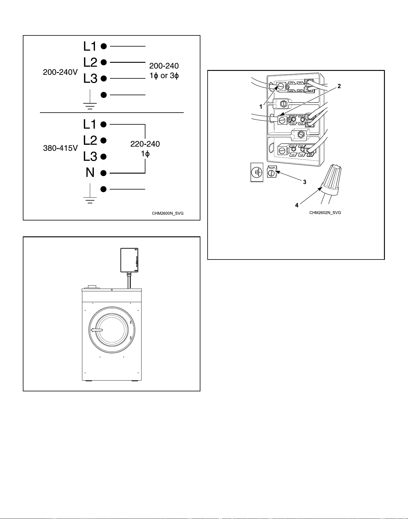
Figure 35
Machine Must Be Hard Wired
CHM2555N_SVG
Figure 36
NOTE: Electrical receptacle must be located so that it
is easily accessible with machine in place. An inter-
mediate shut-off box with a 3 mm gap is required to
meet EN 60335-1, clauses 24.3 and 22.2 or 3.5 mm gap
is required to meet Standard IEC 60335-1, clauses 24.3
and 22.2. Gap is defined as the minimum contact sepa-
ration of each pole in the switch between the “ON” and
“OFF” positions.
Single-Phase Connections
For single-phase input, connect L1, L2 and Ground and cap neu-
tral as shown in Figure 37 .
1. L1
2. L2/N
3. Ground
4. Neutral (capped)
Figure 37
Installation
©
Copyright, Alliance Laundry Systems LLC -
DO NOT COPY or TRANSMIT
73 Part No. F8619501ENR4
Downloaded from www.ManualsFile.com manuals search engine
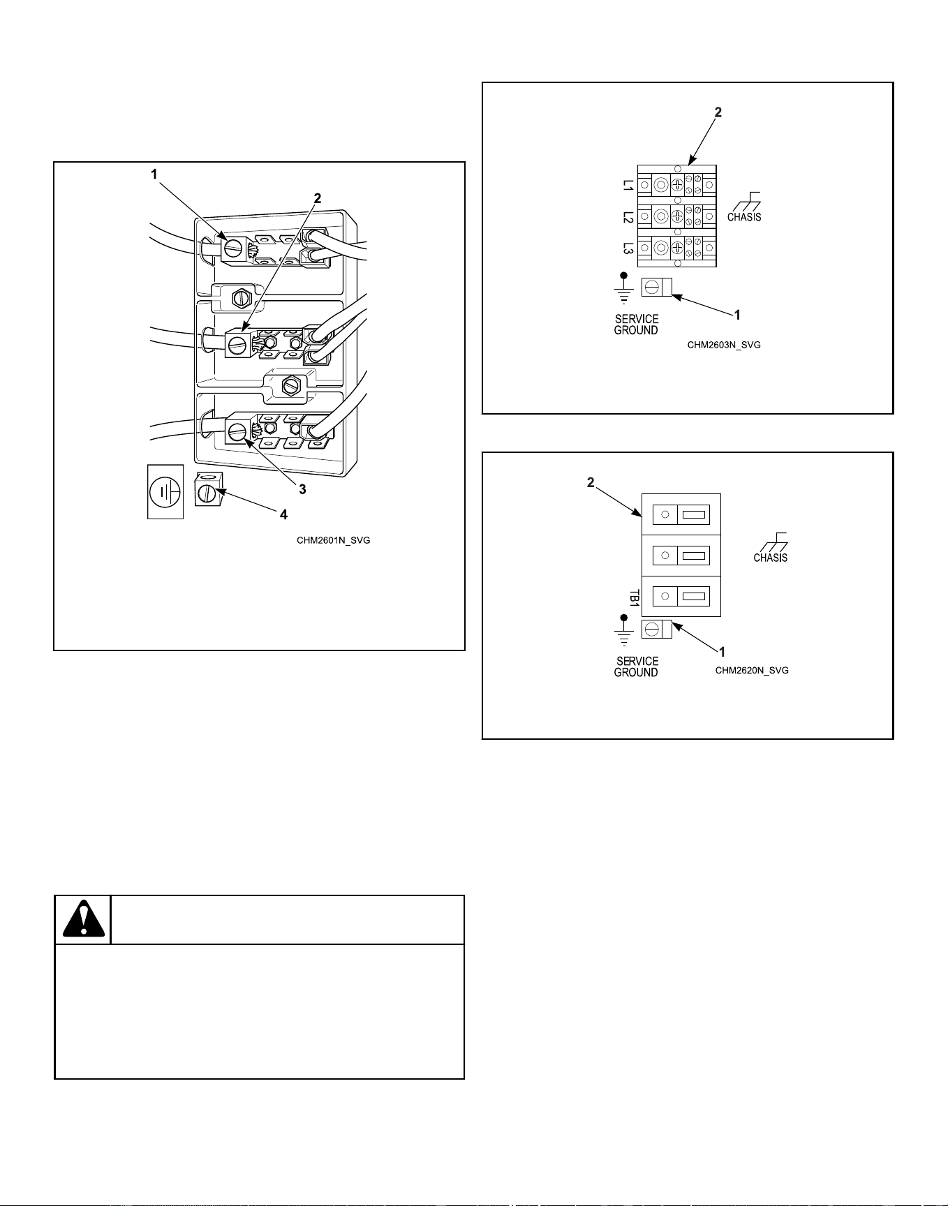
Three-Phase Connections
For three-phase input, connect L1, L2, L3 and Ground as shown
in Figure 38 .
1. L1
2. L2
3. L3
4. Ground
Figure 38
IMPORTANT: If a stinger leg is used for three-phase in-
put, it MUST be connected to L3.
Grounding
For personal safety and proper operation, the machine must be
grounded in accordance with state and local codes. If such codes
are not available, grounding must conform to the National Elec-
tric Code, article 250 (current edition). The ground connection
must be made to a proven earth ground, not to conduit or water
pipes.
WARNING
Electrically heated machines DO NOT require dual
power sources. Do not connect customer power or
customer load to the Internal Load Distribution ter-
minal block. Refer to the machine electrical schemat-
ic for details.
W759
Machines with Electric Heat
1. Grounding Lug: Connect to proven earth ground
2. Customer Input Power Terminals
Figure 39
Machines without Electric Heat
1. Grounding Lug: Connect to proven earth ground
2. Customer Input Power Terminals
Figure 40
Phase Adder
IMPORTANT: Do not use a phase adder on any ma-
chine.
Thermal Overload Protector
The inverter drive provides overload protection for the drive mo-
tor.
Installation
©
Copyright, Alliance Laundry Systems LLC -
DO NOT COPY or TRANSMIT
74 Part No. F8619501ENR4
Downloaded from www.ManualsFile.com manuals search engine
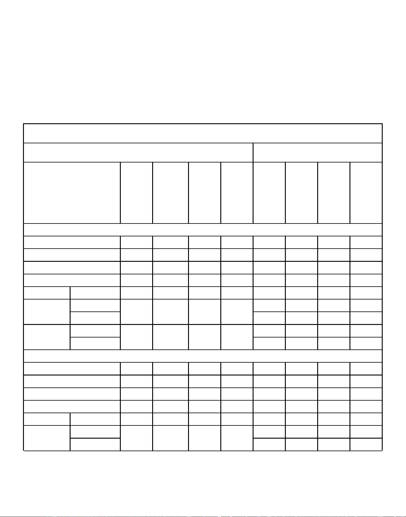
North American Approval
NOTE: Wire sizing listed in this table is based on Arti-
cle 310, Table 310.16 of the NEC; at 104°F [40°C] ambi-
ent temperature. Follow your local electrical codes.
Use only copper conductors, rated for 194ºF [90°C] or
higher, type THHN or better. No more than three current
carrying conductors per raceway. Contact your local
Authority having jurisdiction if you have questions. Cir-
cuit breakers should be UL 489 listed or better. Single
phase circuit breakers for single phase machines only;
three phase circuit breakers for all others.
20 Models - North American Approval
Voltage Designation Specifications
Code
Voltage
Cycle
Phase
Wire
Full Load Amps
Circuit Breaker
AWG
mm
2
F-Speed Models
B 120 60 1 2 8 15 14 2.5
W 200-240 50 1/3 2/3 4/3 15 14 2.5
Y 200-240 60 1/3 2/3 4/3 15 14 2.5
X 200-240 50- 60 1/3 2/3 4/3 15 14 2.5
Q Electric Heat 200-240 50- 60 3 3 22 30 10 6.0
P Standard 380-415 50- 60 3 3 2 15 14 2.5
Electric Heat 12 15 14 2.5
N Standard 440-480 50- 60 3 3 2 15 14 2.5
Electric Heat 14 15 14 2.5
V-Speed Models
B 120 60 1 2 9 15 14 2.5
W 200-240 50 1/3 2/3 4/3 15 14 2.5
Y 200-240 60 1/3 2/3 4/3 15 14 2.5
X 200-240 50- 60 1/3 2/3 4/3 15 14 2.5
Q Electric Heat 200-240 50- 60 3 3 22 30 10 6.0
P Standard 380-415 50- 60 3 3 2 15 14 2.5
Electric Heat 12 15 14 2.5
Table 31 continues...
Installation
©
Copyright, Alliance Laundry Systems LLC -
DO NOT COPY or TRANSMIT
75 Part No. F8619501ENR4
Downloaded from www.ManualsFile.com manuals search engine
20 Models - North American Approval
Voltage Designation Specifications
Code
Voltage
Cycle
Phase
Wire
Full Load Amps
Circuit Breaker
AWG
mm
2
N Standard 440-480 50- 60 3 3 2 15 14 2.5
Electric Heat 14 15 14 2.5
Table 31
Installation
©
Copyright, Alliance Laundry Systems LLC -
DO NOT COPY or TRANSMIT
76 Part No. F8619501ENR4
Downloaded from www.ManualsFile.com manuals search engine
30 Models - North American Approval
Voltage Designation Specifications
Code
Voltage
Cycle
Phase
Wire
Full Load Amps
Circuit Breaker
AWG
mm
2
F-Speed Models
B 120 60 1 2 10 15 14 2.5
W 200-240 50 1/3 2/3 5/4 15 14 2.5
Y 200-240 60 1/3 2/3 5/4 15 14 2.5
X 200-240 50- 60 1/3 2/3 5/4 15 14 2.5
Q Electric
Heat
200-240 50- 60 3 3 22 30 10 6.0
P Standard 380-415 50- 60 3 3 3 15 14 2.5
Electric
Heat
12 15 14 2.5
N 440-480 50- 60 3 3 3 15 14 2.5
14 15 14 2.5
V-Speed Models
B 120 60 1 2 12 15 12 4
W 200-240 50 1/3 2/3 7/4 15 14 2.5
Y 200-240 60 1/3 2/3 7/4 15 14 2.5
X 200-240 50- 60 1/3 2/3 7/4 15 14 2.5
Q Electric
Heat
200-240 50- 60 3 3 22 30 10 6.0
P Standard 380-415 50- 60 3 3 3 15 14 2.5
Electric
Heat
12 15 14 2.5
N Standard 440-480 50- 60 3 3 3 15 14 2.5
Electric
Heat
14 15 14 2.5
Table 32
Installation
©
Copyright, Alliance Laundry Systems LLC -
DO NOT COPY or TRANSMIT
77 Part No. F8619501ENR4
Downloaded from www.ManualsFile.com manuals search engine
40 Models - North American Approval
Voltage Designation Specifications
Code
Voltage
Cycle
Phase
Wire
Full Load Amps
Circuit Breaker
AWG
mm
2
F-Speed Models
B 120 60 1 2 10 15 14 2.5
W 200-240 50 1/3 2/3 6/4 15 14 2.5
Y 200-240 60 1/3 2/3 6/4 15 14 2.5
X 200-240 50- 60 1/3 2/3 6/4 15 14 2.5
Q Electric
Heat
200-240 50- 60 3 3 41 50 8 10.0
P Standard 380-415 50- 60 3 3 3 15 14 2.5
Electric
Heat
24 30 10 6.0
N Standard 440-480 50- 60 3 3 3 15 14 2.5
Electric
Heat
22 30 10 6.0
V-Speed Models
B 120 60 1 2 12 15 12 2.5
W 200-240 50 1 2/3 7/4 15 14 2.5
Y 200-240 60 1/3 2/3 7/4 15 14 2.5
X 200-240 50- 60 1/3 2/3 7/4 15 14 2.5
Q Electric
Heat
200-240 50- 60 3 3 41 50 8 10.0
P Standard 380-415 50- 60 3 3 3 15 14 2.5
Electric
Heat
24 30 10 6.0
N Standard 440-480 50- 60 3 3 3 15 14 2.5
Electric
Heat
22 30 10 6.0
Table 33
Installation
©
Copyright, Alliance Laundry Systems LLC -
DO NOT COPY or TRANSMIT
78 Part No. F8619501ENR4
Downloaded from www.ManualsFile.com manuals search engine
60 Models - North American Approval
Voltage Designation Specifications
Code
Voltage
Cycle
Phase
Wire
Full Load Amps
Circuit Breaker
AWG
mm
2
F-Speed Models
X 200-240 50- 60 1/3 2/3 8/5 15 14 2.5
Q Electric
Heat
200-240 50- 60 3 3 41 50 8 10.0
P Standard 380-415 50- 60 3 3 4 15 14 2.5
Electric
Heat
26 30 10 6.0
N Standard 440-480 50- 60 3 3 4 15 14 2.5
Electric
Heat
22 30 10 6.0
V-Speed Models
X 200-240 50- 60 1/3 2/3 11/7 15 14 2.5
Q Electric
Heat
200-240 50- 60 3 3 41 50 8 10.0
P Standard 380-415 50- 60 3 3 4 15 14 2.5
Electric
Heat
26 30 10 6.0
N Standard 440-480 50- 60 3 3 4 15 14 2.5
Electric
Heat
22 30 10 6.0
Table 34
Installation
©
Copyright, Alliance Laundry Systems LLC -
DO NOT COPY or TRANSMIT
79 Part No. F8619501ENR4
Downloaded from www.ManualsFile.com manuals search engine
80 Models - North American Approval
Voltage Designation Specifications
Code
Voltage
Cycle
Phase
Wire
Full Load Amps
Circuit Breaker
AWG
mm
2
F-Speed Models
X 200-240 50- 60 1/3 2/3 12/8 15 14 2.5
Q Electric
Heat
200-240 50- 60 3 3 73 80 4 25.0
P Standard 380-415 50- 60 3 3 5 15 14 2.5
Electric
Heat
33 40 8 10.0
N Standard 440-480 50- 60 3 3 5 15 14 2.5
Electric
Heat
36 40 8 10.0
V-Speed Models
X 200-240 50- 60 1/3 2/3 15/9 20/15 12/14 4/2.5
Q Electric
Heat
200-240 50- 60 3 3 73 80 4 25.0
P Standard 380-415 50- 60 3 3 6 15 14 2.5
Electric
Heat
33 40 8 10.0
N Standard 440-480 50- 60 3 3 6 15 14 2.5
Electric
Heat
36 40 8 10.0
Table 35
Installation
©
Copyright, Alliance Laundry Systems LLC -
DO NOT COPY or TRANSMIT
80 Part No. F8619501ENR4
Downloaded from www.ManualsFile.com manuals search engine
100 Models - North American Approval
Voltage Designation Specifications
Code
Voltage
Cycle
Phase
Wire
Full Load Amps
Circuit Breaker
AWG
mm
2
F-Speed Models
X 200-240 50- 60 1/3 2/3 12/8 15 14 2.5
Q Electric
Heat
200-240 50- 60 3 3 74 80 4 25.0
P Standard 380-415 50- 60 3 3 5 15 14 2.5
Electric
Heat
32 40 8 10.0
N Standard 440-480 50- 60 3 3 5 15 14 2.5
Electric
Heat
36 40 8 10.0
V-Speed Models
X 200-240 50- 60 1/3 2/3 16/10 20/15 12/14 4/2.5
Q Electric
Heat
200-240 50- 60 3 3 74 80 4 25.0
P Standard 380-415 50- 60 3 3 6 15 14 2.5
Electric
Heat
32 40 8 10.0
N Standard 440-480 50- 60 3 3 6 15 14 2.5
Electric
Heat
36 40 8 10.0
Table 36
Installation
©
Copyright, Alliance Laundry Systems LLC -
DO NOT COPY or TRANSMIT
81 Part No. F8619501ENR4
Downloaded from www.ManualsFile.com manuals search engine
CE Approval
NOTE: Wire sizing listed in this table is based on Arti-
cle 310, Table 310.16 of the NEC; at 104°F [40°C] ambi-
ent temperature. Follow your local electrical codes.
Use only copper conductors, rated for 194ºF [90°C] or
higher, type THHN or better. No more than three current
carrying conductors per raceway. Contact your local
Authority having jurisdiction if you have questions. Cir-
cuit breakers should be UL 489 listed or better. Single
phase circuit breakers for single phase machines only;
three phase circuit breakers for all others.
NOTE: N and P Voltage - Where the protective conduc-
tor has a cross-sectional area of less than 10 mm2 Cu,
a second protective conductor of at least the same
cross-sectional area shall be provided up to a point
where the protective conductor has a cross-sectional
area not less than 10 mm2 Cu.
20 Models - CE Approval
Voltage Designation Specifications
Code
Voltage
Cycle
Phase
Wire
Full Load Amps
Circuit Breaker
mm
2
F-Speed Models
B 120 60 1 2 8 10 2.5
W 200-240 50 1/3 2/3 4/3 6 2.5
Y 200-240 60 1/3 2/3 4/3 6 2.5
X 200-240 50-60 1/3 2/3 4/3 6 2.5
Q Electric Heat 200-240 50-60 3 3 17- 20 25 2.5
P Standard 380-415 50-60 3 3 2 6 2.5
Electric Heat 11 16 2.5
N 440-480 50-60 3 3 2 6 2.5
V-Speed Models
B 120 60 1 2 9 10 2.5
W 200-240 50 1/3 2/3 4 6 2.5
Y 200-240 60 1/3 2/3 4 6 2.5
X 200-240 50-60 1/3 2/3 4/3 6 2.5
Q Electric Heat 200-240 50-60 3 3 17- 20 25 2.5
P Standard 380-415 50-60 3 3 2 6 2.5
Electric Heat 11 16 2.5
N 440-480 50-60 3 3 2 6 2.5
Table 37
Installation
©
Copyright, Alliance Laundry Systems LLC -
DO NOT COPY or TRANSMIT
82 Part No. F8619501ENR4
Downloaded from www.ManualsFile.com manuals search engine
30 Models - CE Approval
Voltage Designation Specifications
Code
Voltage
Cycle
Phase
Wire
Full Load Amps
Circuit Breaker
mm
2
F-Speed Models
B 120 60 1 2 10 10 2.5
W 200-240 50 1/3 2/3 5/4 6 2.5
Y 200-240 60 1/3 2/3 5/4 6 2.5
X 200-240 50-60 1/3 2/3 5/4 6 2.5
Q Electric Heat 200-240 50-60 3 3 17- 20 25 2.5
P Standard 380-415 50-60 3 3 3 6 2.5
Electric Heat 11 16 2.5
N 440-480 50-60 3 3 3 6 2.5
V-Speed Models
B 120 60 1 2 12 16 2.5
W 200-240 50 1/3 2/3 7/4 10/6 2.5
Y 200-240 60 1/3 2/3 7/4 10/6 2.5
X 200-240 50-60 1/3 2/3 7/4 10/6 2.5
Q Electric Heat 220-240 50-60 3 3 17- 20 25 2.5
P Standard 380-415 50-60 3 3 3 6 2.5
Electric Heat 11 16 2.5
N 440-480 50-60 3 3 3 6 2.5
Table 38
Installation
©
Copyright, Alliance Laundry Systems LLC -
DO NOT COPY or TRANSMIT
83 Part No. F8619501ENR4
Downloaded from www.ManualsFile.com manuals search engine
40 Models - CE Approval
Voltage Designation Specifications
Code
Voltage
Cycle
Phase
Wire
Full Load Amps
Circuit Breaker
mm
2
F-Speed Models
B 120 60 1 2 10 10 2.5
W 200-240 50 1/3 2/3 6/4 6 2.5
Y 200-240 60 1/3 2/3 6/4 6 2.5
X 200-240 50-60 1/3 2/3 7/4 10/6 2.5
Q Electric Heat 220-240 50-60 3 3 33- 39 50 10.0
P Standard 380-415 50-60 3 3 3 6 2.5
Electric Heat 23 25 2.5
N Standard 440-480 50-60 3 3 3 6 2.5
Electric Heat 20 25 2.5
V-Speed Models
B 120 60 1 2 12 16 2.5
W 200-240 50 1/3 2/3 7/4 10/6 2.5
Y 200-240 60 1/3 2/3 7/4 10/6 2.5
X 200-240 50-60 1/3 2/3 7/4 10/6 2.5
Q Electric Heat 200-240 50-60 3 3 33- 39 50 10.0
P Standard 380-415 50-60 3 3 3 6 2.5
Electric Heat 23 32 2.5
N Standard 440-480 50-60 3 3 3 6 2.5
Electric Heat 30 25 2.5
Table 39
Installation
©
Copyright, Alliance Laundry Systems LLC -
DO NOT COPY or TRANSMIT
84 Part No. F8619501ENR4
Downloaded from www.ManualsFile.com manuals search engine
60 Models - CE Approval
Voltage Designation Specifications
Code
Voltage
Cycle
Phase
Wire
Full Load Amps
Circuit Breaker
mm
2
F-Speed Models
X 200-240 50-60 1/3 2/3 8/5 10/6 2.5
220-240
Q Electric Heat 200-240 50-60 3 3 33- 39 50 10.0
P Standard 380-415 50-60 3 3 4 6 2.5
Electric Heat 23 32 2.5
N Standard 440-480 50-60 3 3 4 6 2.5
Electric Heat 20 25 2.5
V-Speed Models
X 200–240 50-60 1/3 2/3 11/7 16/ 10 2.5
Q Electric Heat 200-240 50-60 3 3 33- 39 50 10.0
P Standard 380-415 50-60 3 3 4 6 2.5
Electric Heat 23 32 2.5
N Standard 440-480 50-60 3 3 4 6 2.5
Electric Heat 20 25 2.5
Table 40
Installation
©
Copyright, Alliance Laundry Systems LLC -
DO NOT COPY or TRANSMIT
85 Part No. F8619501ENR4
Downloaded from www.ManualsFile.com manuals search engine
80 Models - CE Approval
Voltage Designation Specifications
Code
Voltage
Cycle
Phase
Wire
Full Load Amps
Circuit Breaker
mm
2
F-Speed Models
X 200-240 50-60 1/3 2/3 12/8 16/ 10 2.5
Q Electric Heat 200-240 50-60 3 3 59- 70 80 16.0
P Standard 380-415 50-60 3 3 5 6 2.5
Electric Heat 30 40 4.0
N Standard 440-480 50-60 3 3 5 6 2.5
Electric Heat 35 40 4.0
V-Speed Models
X 200-240 50-60 1/3 2/3 17/ 11 20/ 16 2.5
Q Electric Heat 200-240 50-60 3 3 59- 70 80 16.0
P Standard 380-415 50-60 3 3 7 10 2.5
Electric Heat 30 40 4.0
N Standard 440-480 50-60 3 3 7 10 2.5
Electric Heat 35 40 4.0
Table 41
Installation
©
Copyright, Alliance Laundry Systems LLC -
DO NOT COPY or TRANSMIT
86 Part No. F8619501ENR4
Downloaded from www.ManualsFile.com manuals search engine

100 Models - CE Approval
Voltage Designation Specifications
Code
Voltage
Cycle
Phase
Wire
Full Load Amps
Circuit Breaker
mm
2
F-Speed Models
X 200-240 50-60 1/3 2/3 12/8 10/ 16 2.5
Q Electric Heat 220-240 50-60 3 3 59- 70 80 16.0
P Standard 380-415 50-60 3 3 5 6 2.5
Electric Heat 30 40 4.0
N Standard 440-480 50-60 3 3 5 6 2.5
Electric Heat 35 40 4.0
V-Speed Models
X 200-240 50-60 1/3 2/3 17/ 11 20/ 16 2.5
Q Electric Heat 220-240 50-60 3 3 59- 70 80 16.0
P Standard 380-415 50-60 3 3 7 10 2.5
Electric Heat 30 40 4.0
N Standard 440-480 50-60 3 3 7 10 2.5
Electric Heat 35 40 4.0
Table 42
Installation
©
Copyright, Alliance Laundry Systems LLC -
DO NOT COPY or TRANSMIT
87 Part No. F8619501ENR4
Downloaded from www.ManualsFile.com manuals search engine
Steam Requirements (Steam Heat
Option Only)
WARNING
Hot Surfaces. Will cause severe burns. Turn steam
off and allow steam pipes, connections and compo-
nents to cool before touching.
W505
For machines equipped with optional steam heat, install piping in
accordance with approved commercial steam practices. Steam re-
quirements are shown in Table 1.
Chemical Injection Supply System
WARNING
Dangerous Chemicals. May damage eyes and skin.
Wear eye and hand protection when handling chemi-
cals; always avoid direct contact with raw chemicals.
Read the manufacturer’s directions for accidental
contact before handling chemicals. Ensure an eye-
rinse facility and an emergency shower are within
easy reach. Check at regular intervals for chemical
leaks.
W363
IMPORTANT: Undiluted chemical dripping can damage
the machine. All chemical injection supply dispenser
pumps and dispenser tubing should be mounted below
the washer’s injection point. Loops do not prevent
drips if these instructions are not followed. Figure 43
shows a typical Chemical Injection Supply System.
IMPORTANT: Failure to follow these instructions could
damage the machine and void the warranty.
The chemical supply connector is located on the back right-hand
side of the machine. There are 12 chemical ports on the connec-
tor, through each a liquid supply hose can be connected. A flush
manifold system can only be connected through the top 6 ports
(refer to Figure 42 ).
IMPORTANT: Water pressure must not exceed 40 psi
[275 kPa].
1. Drill through the ports on the chemical supply connector as
needed for the external supply hoses.
NOTE: 3/8 inch ports must be drilled through with a
3/16 inch diameter drill bit and 1/2 inch ports must
be drilled through with a 5/16 inch diameter drill bit
before connecting chemical lines. Refer to Figure
42 .
IMPORTANT: Be careful to only drill through the first
wall so as not to damage the machine.
2. Remove plastic debris.
3. Attach the external supply hoses to the ports at each of the
drilled holes.
4. Secure with proper clamps.
CAUTION
Drill out plugs and nipples before making supply
hose connection. Failure to do so can cause buildup
of pressure and risk a tubing rupture.
W491
Supply Dispensing
Number of liquid chemical supply signals (if
equipped)
4 or 8
Number of supply compartments 4
Number of external liquid supply connections 12
Table 43
Installation
©
Copyright, Alliance Laundry Systems LLC -
DO NOT COPY or TRANSMIT
88 Part No. F8619501ENR4
Downloaded from www.ManualsFile.com manuals search engine
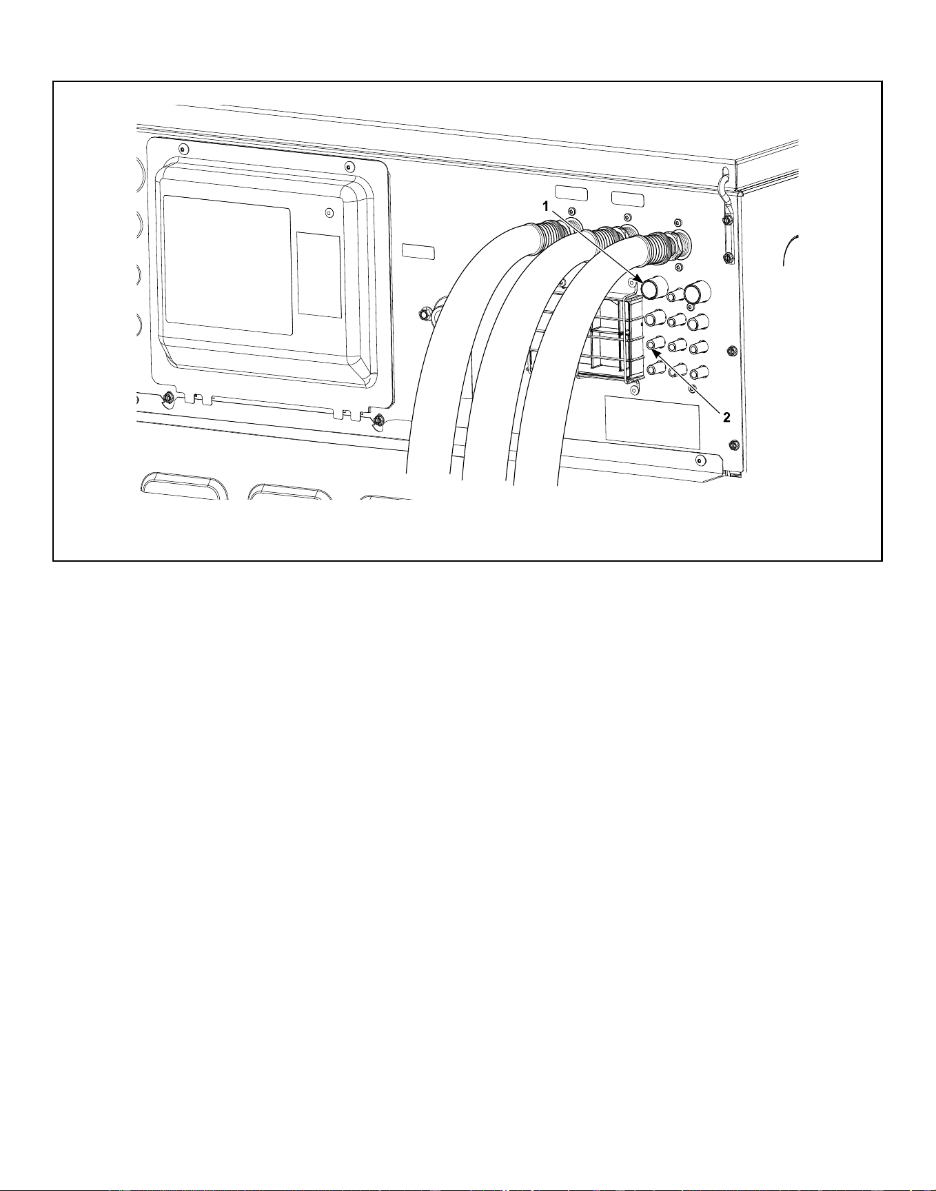
Connection for Chemical Supply Hoses (refer to Figure 42 for detail of chemical supply connector)
C-CHM1N1_SVG1
1. Chemical Supply Connector
2. External Liquid Supply Connection Ports (12)
Figure 41
Installation
©
Copyright, Alliance Laundry Systems LLC -
DO NOT COPY or TRANSMIT
89 Part No. F8619501ENR4
Downloaded from www.ManualsFile.com manuals search engine
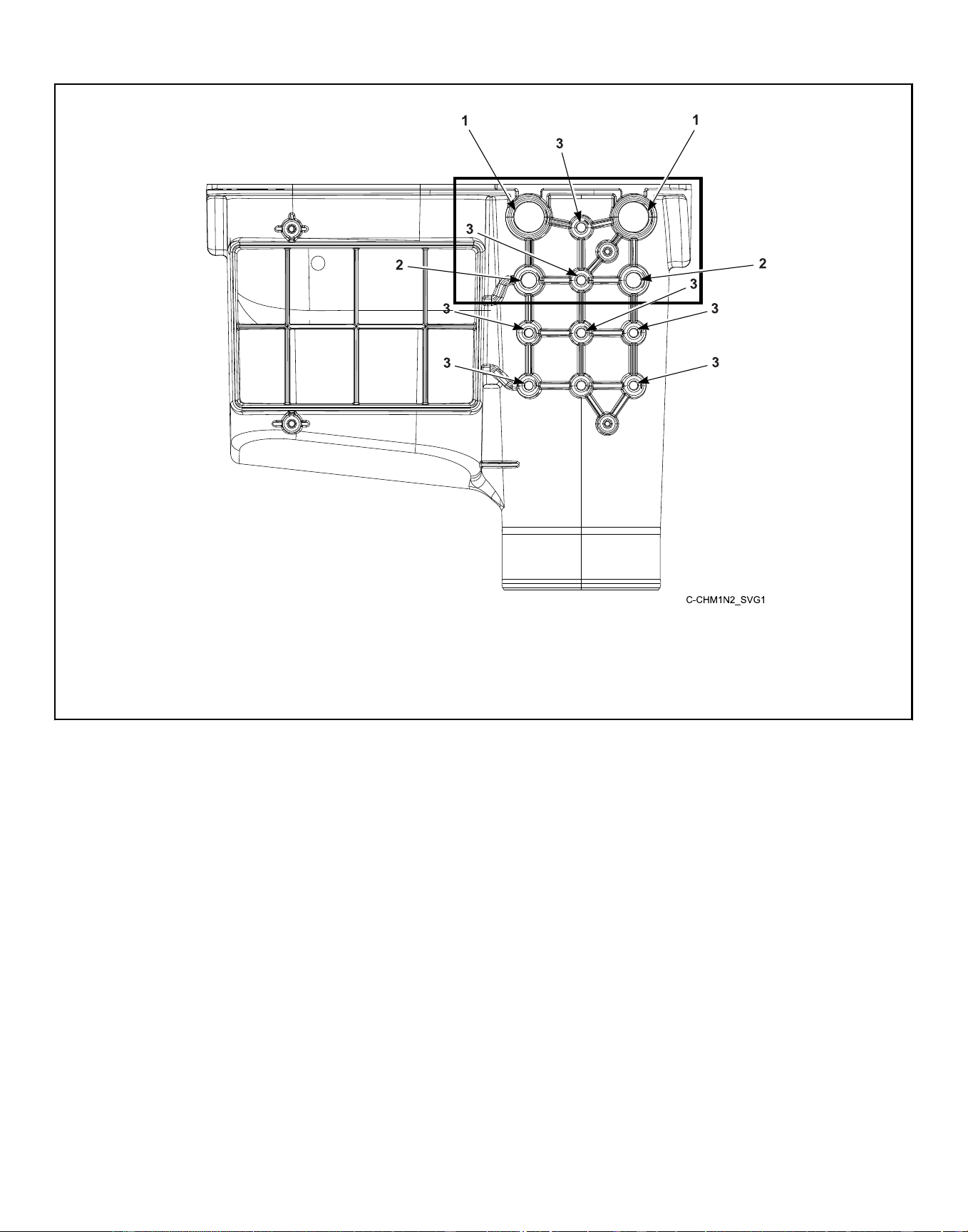
External Liquid Supply Connection Ports
NOTE: A flush manifold system can only be connected through the top 6 ports (boxed).
1. 3/4 inch port, O.D.
2. 1/2 inch port, O.D.
3. 3/8 inch port, O.D.
Figure 42
Installation
©
Copyright, Alliance Laundry Systems LLC -
DO NOT COPY or TRANSMIT
90 Part No. F8619501ENR4
Downloaded from www.ManualsFile.com manuals search engine
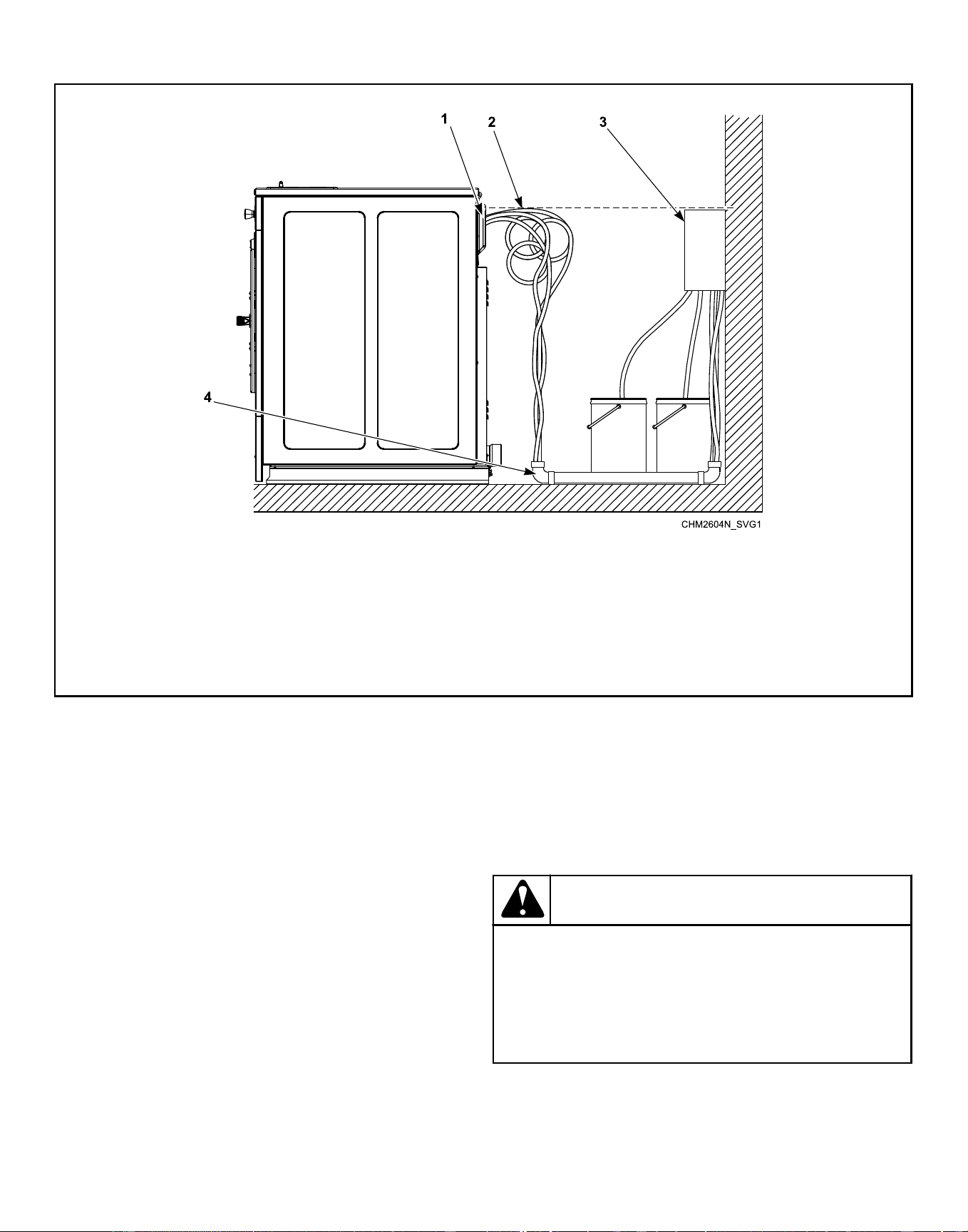
Chemical Supply Setup
* Use a check valve on the end of tubing
† Pumps must be mounted below the injection point
1. Injection Point*
2. Loops
3. Chemical Dispenser Pump Outlet †
4. PVC Pipe
Figure 43
External Supplies
For proper communication between the machine and an external
chemical supply system, it is important for the low-voltage signal
power to be connected properly. The included wiring diagram
shows several different options for safe and correct wiring of this
interface.
The preferred method for connecting the wiring from the external
chemical supply system to the machine is to use the 300mA pow-
er of the machine’s 24VAC control transformer, which is intended
strictly for this purpose. Refer to Figure 44 and Figure 45 . Other
voltage and current options are available, but require some wiring
changes and must be provided with an external power source.
Under no circumstances should the high-voltage machine supply
connections or source be used for the communication wiring.
Communication wiring connections, which is H2 a single row
green connector on a small output board, can be found under a
service panel at the upper back of the machine.
Chemical Injection Using Internal 24VAC Control
Transformer
NOTE: Using the Internal 24VAC 300 Milliamp Control
Transformer is recommended by Alliance Laundry Sys-
tems.
CAUTION
Do not attempt to increase fuse rating or alter wiring
of external chemical supply terminal strip in such as
way that may conflict with the suggested methods
provided on the Optional External Supply Wiring Dia-
gram.
W699
IMPORTANT: Do not use the transformer terminals if an
external power supply is used.
Installation
©
Copyright, Alliance Laundry Systems LLC -
DO NOT COPY or TRANSMIT
91 Part No. F8619501ENR4
Downloaded from www.ManualsFile.com manuals search engine
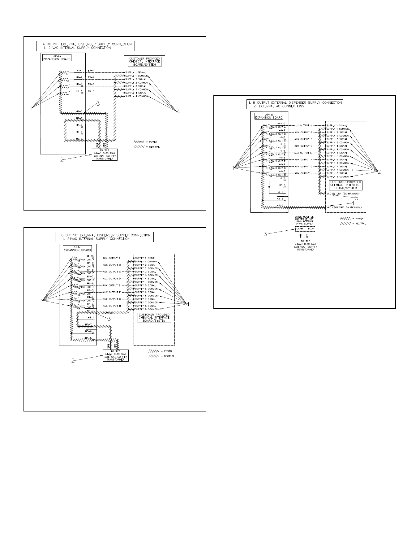
CHM2570N_SVG
1. External Supply Power Output
2. Internal Control Transformer
3. RELAY COM Terminal
4. External Dispenser Input Signal Common
Figure 44
CHM2571N_SVG
1. External Supply Power Output
2. Internal Control Transformer
3. RELAY COM Terminal
4. External Dispenser Input Signal Common
Figure 45
Chemical Injection Using External AC Power
Source
NOTE: An External AC Power Source is NOT provided
by Alliance Laundry Systems.
NOTE: Power for external supplies must not be derived
from the high-voltage main power connection point.
IMPORTANT: The external power must supply power of
240VAC or less and be protected at 3 Amps or less.
1. Disconnect and cap off the Red and White 24VAC wires.
2. Connect one side of the external power to the “RELAY
COM” and the other to the external dispenser input signals
common. Refer to Figure 46 and Figure 47 .
CHM2573N_SVG
1. External Supply Power Output
2. External Dispencer Input Signal Common
3. Capped Off 24VAC Supply
4. VAC Terminal
5. VAC COM Terminal
Figure 46
Installation
©
Copyright, Alliance Laundry Systems LLC -
DO NOT COPY or TRANSMIT
92 Part No. F8619501ENR4
Downloaded from www.ManualsFile.com manuals search engine
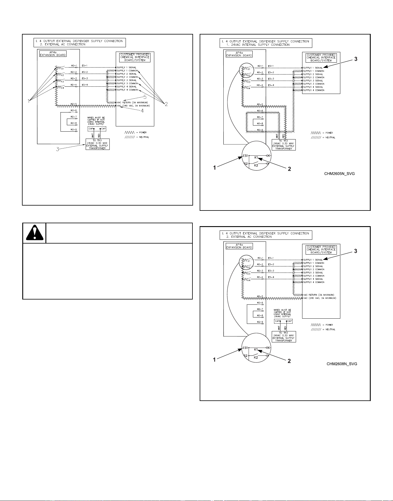
CHM2572N_SVG
1. External Dispencer Power Output
2. External Dispencer Input Signal Common
3. Capped Off 24VAC Supply
4. VAC Terminal
5. VAC COM Terminal
Figure 47
CAUTION
Do not attempt to increase fuse rating or alter wiring
of external chemical supply terminal strip in such as
way that may conflict with the suggested methods
provided on the Optional External Supply Wiring Dia-
gram.
W699
External Supply Signals
Wash-cycle signals are provided to the external chemical supply
equipment and a “wait for the next step” signal can be received
from the supply equipment.
For example of a 4-signal board, if ES1 is selected the K1 contact
will close and power will be supplied to Supply 1 Signal. The
contact will remain closed for the amount of time programmed in
control. Refer to Figure 48 for Internal Supply Connection or
Figure 50 for External AC Connection.
For example of an 8-signal board, if ES1 is selected the K12 con-
tact will close and power will be supplied to Supply 1 Signal. The
contact will remain closed for the amount of time programmed in
control. Refer to Figure 49 for Internal Supply Connection or and
Figure 51 for External AC Connection.
1. ES1 Power supply
2. K1 Contact
3. Supply 1 Signal
Figure 48
1. ES1 Power supply
2. K1 Contact
3. Supply 1 Signal
Figure 49
Installation
©
Copyright, Alliance Laundry Systems LLC -
DO NOT COPY or TRANSMIT
93 Part No. F8619501ENR4
Downloaded from www.ManualsFile.com manuals search engine
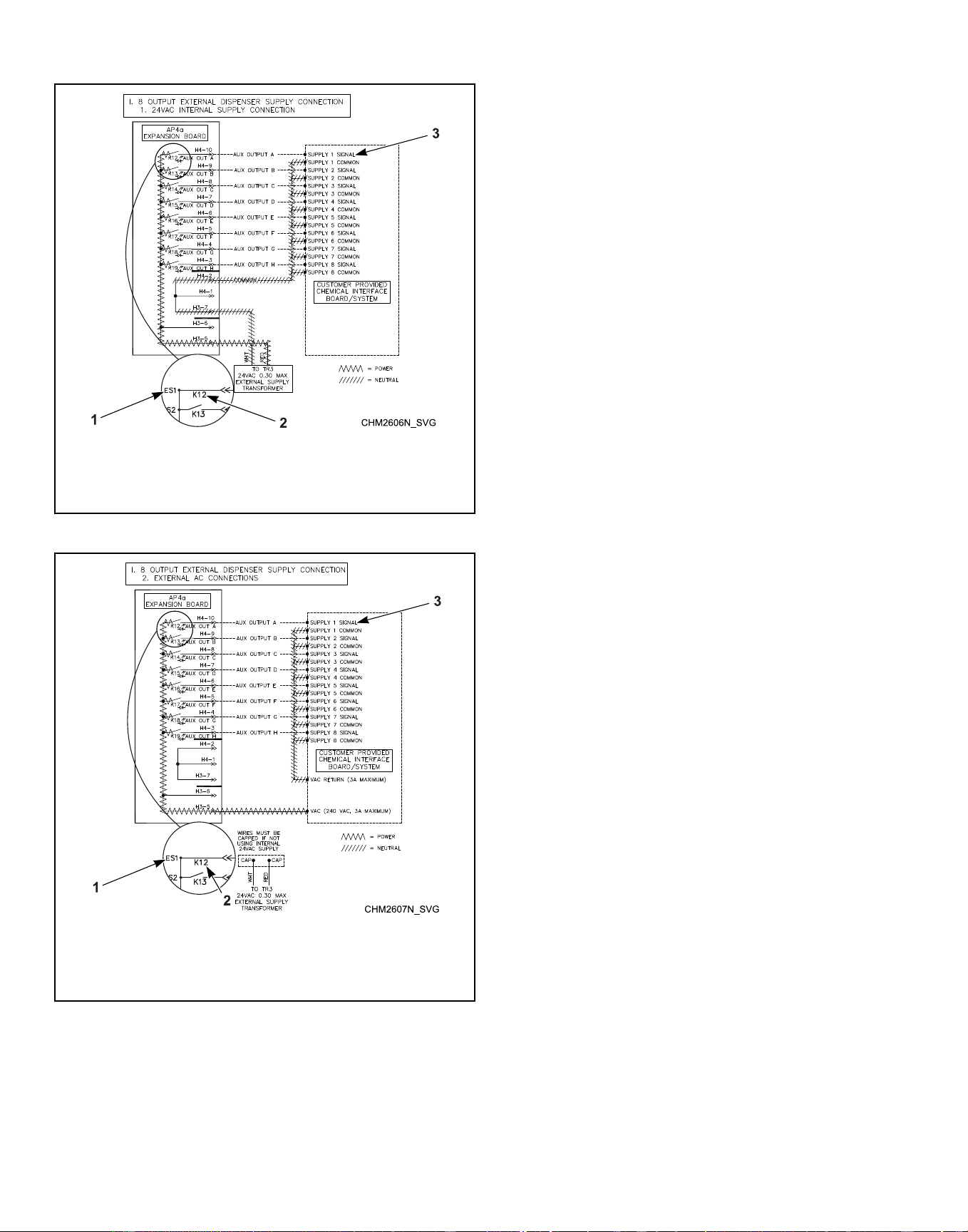

Start Up
Basket Rotation
After installation is complete, run the machine through a test cy-
cle and check that basket rotation is counter clockwise in the ex-
tract step.
1. If rotation is not counter clockwise, disconnect power to ma-
chine.
2. Have a qualified electrician reverse any two motor leads at
the motor.
Start Up
©
Copyright, Alliance Laundry Systems LLC -
DO NOT COPY or TRANSMIT
95 Part No. F8619501ENR4
Downloaded from www.ManualsFile.com manuals search engine
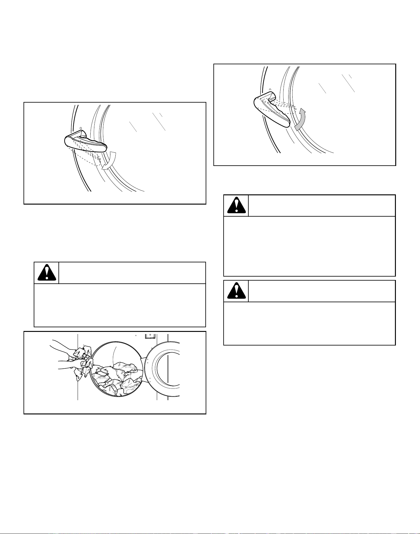
Operation
Operating Instructions
1. Turn on main power source (circuit breaker).
2. Turn handle clockwise to open. Refer to Figure 52 .
CHM2243N_SVG
Figure 52
3. Load to capacity whenever possible. DO NOT OVERLOAD.
Refer to Figure 53 .
NOTE: Underloading can cause out-of-balance con-
ditions that can shorten machine life.
CAUTION
Be careful around the open door, particularly
when loading from a level below the door. Impact
with door edges can cause personal injury.
SW025
U003I_SVG
Figure 53
NOTE: When washing items which may disintegrate
or fragment, such as mop heads or sponges, use
laundry nets to prevent drain blockage.
IMPORTANT: To prevent out-of-balance conditions,
premature wear or damage to machine when using
laundry nets, use several small nets in a load.
4. Close the door and turn handle counter clockwise. Refer to
Figure 54 .
CHM2244N_SVG
Figure 54
5. Refer to OPL Control Instructions to select and start a cycle.
CAUTION
Water cannot be extracted from rubber backed
items. To avoid damage to machine from out of
balance conditions, do not use a spin (extract)
step when washing rubber backed items. Warran-
ty will be voided.
W880
WARNING
To prevent personal injury, avoid contact with in-
let water temperatures higher than 125° Fahren-
heit [51° Celsius] and hot surfaces.
W748
Operation
©
Copyright, Alliance Laundry Systems LLC -
DO NOT COPY or TRANSMIT
96 Part No. F8619501ENR4
Downloaded from www.ManualsFile.com manuals search engine
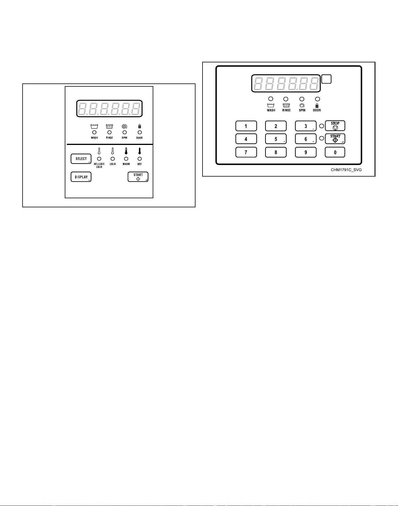
OPL Control Instructions
NOTE: The control digit is the 7th digit in the model
number. Example: HCT020[Q]N0VXU400000
Models with F Control
CHM2561N_SVG
Figure 55
1. If display has gone blank due to sitting idle, press the DIS-
PLAY keypad.
2. Press the SELECT keypad to choose Delicate Cold, Cold,
Warm or Hot. The corresponding LED indicates the selection.
3. Add liquid and/or powder supplies to supply dispenser. Refer
to Table 44 .
a. Detergent:
• Liquid - Compartment 1 (prewash) + Compartment 3
• Powder - Compartment 1 (prewash) + Compartment 2
b. Bleach:
• Liquid - Compartment 3
• Powder - Compartment 2
c. Softener:
• Liquid - Compartment 4
4. Press the START (enter) keypad to select.
NOTE: Cycles can be changed anytime during the
first Fill Step. After the first Fill Step, all cycle key-
pad presses are ignored.
5.
When a cycle is complete, the control displays 00.
SCA, SCD, SCG, SCH, SCJ, SCT, SCU, UCA, UCD,
UCG, UCH, UCJ, UCT and UCU Models with N Con-
trol
Figure 56
1. If equipped with an optional supply dispenser, add dry sup-
plies to the compartment cups prior to the start of each cycle.
Liquid supplies can be injected directly into the supply dis-
penser by an external chemical supply system.
NOTE: Supply dispenser compartment cups must
not be removed when an external chemical injection
supply system is attached to the machine.
2. Press the 1, 2, 3, 4, 5, 6, 7, 8, 9 or 0 keypad to select the de-
sired cycle.
3. Add liquid and/or powder supplies to supply dispenser. Refer
to Table 44 .
a. Detergent:
• Liquid - Compartment 1 (prewash) + Compartment 3
• Powder - Compartment 1 (prewash) + Compartment 2
b. Bleach:
• Liquid - Compartment 3
• Powder - Compartment 2
c. Softener:
• Liquid - Compartment 4
4. Press the START (enter) keypad to select.
NOTE: Cycles cannot be changed anytime after the
machine is started.
5.
When a cycle is complete, the control displays OPEN DOOR.
Operation
©
Copyright, Alliance Laundry Systems LLC -
DO NOT COPY or TRANSMIT
97 Part No. F8619501ENR4
Downloaded from www.ManualsFile.com manuals search engine
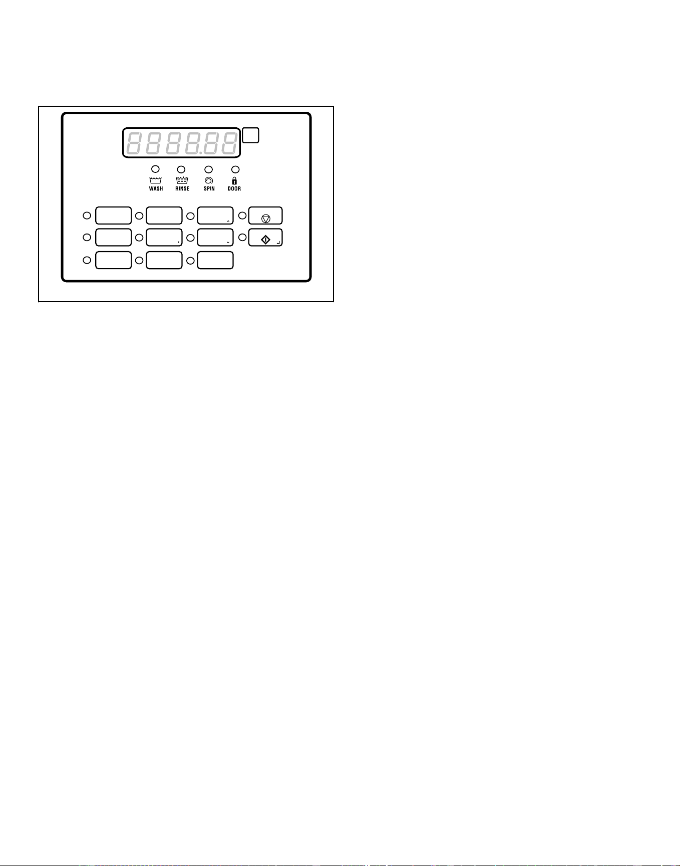
HCA, HCD, HCG, HCH, HCJ, HCT and HCU, UCA,
UCD, UCG, UCH, UCJ, UCT and UCU Models with
Q Control
1
2 3
4
5 6
7
8 9
CHM1792C_SVG
START
STOP
Figure 57
1. Press the 1, 2, 3, 4, 5, 6, 7, 8 or 9 keypad to select the desired
cycle.
2. Add liquid and/or powder supplies to supply dispenser. Refer
to Table 44 .
a. Detergent:
• Liquid - Compartment 1 (prewash) + Compartment 3
• Powder - Compartment 1 (prewash) + Compartment 2
b. Bleach:
• Liquid - Compartment 3
• Powder - Compartment 2
c. Softener:
• Liquid - Compartment 4
3. Press the START (enter) keypad to select.
NOTE: Cycles cannot be changed anytime after the
machine is started.
4.
When a cycle is complete, the control displays OPEN DOOR.
Operation
©
Copyright, Alliance Laundry Systems LLC -
DO NOT COPY or TRANSMIT
98 Part No. F8619501ENR4
Downloaded from www.ManualsFile.com manuals search engine
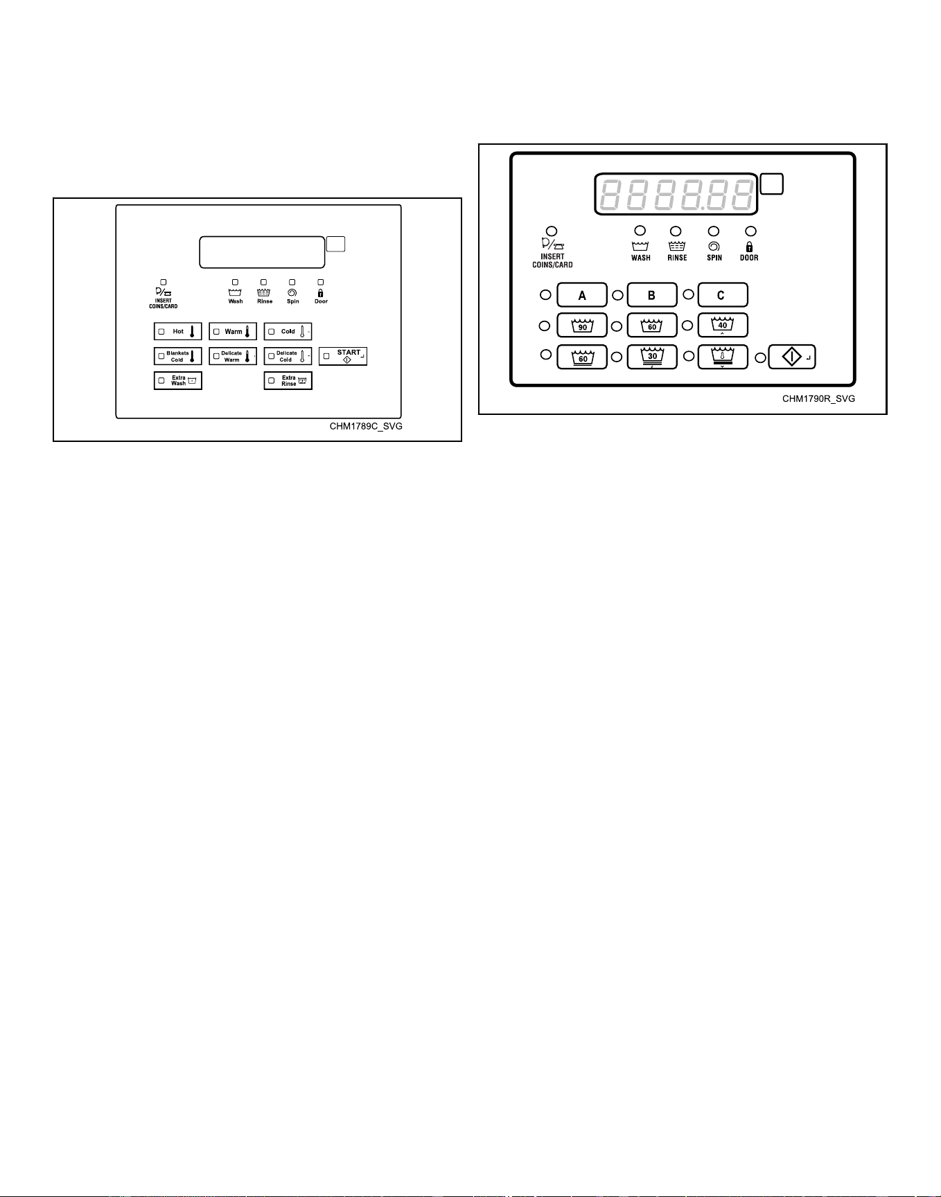
Vend Control Instructions
NOTE: The control digit is the 7th digit in the model
number. Example: HCT020[N]C1VXU400000
HCT Models with N and W Controls
Figure 58
1. Press the Hot, Warm, Cold, Blankets Cold, Delicate Warm or
Delicate Cold keypad to choose the desired cycle/tempera-
ture. The corresponding LED indicates the selection.
2. Press the Extra Wash and/or Exra Rinse keypads to add modi-
fiers to the cycle. The corresponding LEDs indicate the added
modifiers.
3. Insert coin(s) or card as necessary.
• If the machine is a coin operated unit, add coins. As each
coin is added, the vend counts down to the amount re-
maining.
• If the machine is a card operated unit, insert and remove
card per card system instructions.
• If the unit is interfaced to a central/remote pay system, go
to the central/remote pay console, make payment and se-
lect the machine and follow central/remote pay system in-
structions.
4. Add liquid and/or powder supplies to supply dispenser. Refer
to Table 44 .
a. Detergent:
• Liquid - Compartment 1 (prewash) + Compartment 3
• Powder - Compartment 1 (prewash) + Compartment 2
b. Bleach:
• Liquid - Compartment 3
• Powder - Compartment 2
c. Softener:
• Liquid - Compartment 4
5. Press the START (enter) keypad to select.
NOTE: Cycles can be changed anytime during the
first Fill Step. After the first Fill Step, all cycle key-
pad presses are ignored.
6.
When a cycle is complete, the control displays OPEN DOOR.
SCA, SCE, SCG, SCJ and SCU Models with N and
W Controls
Figure 59
1. Press the Normal 90C, Normal 60C, Normal 40C, Perminant
Press 60C, Delecates 30C or Delecates Cold keypad to select
the desired cycle/temperature. The corresponding LED indi-
cates the selection.
2. Press the A keypad to run the selected cycle with no modifi-
ers. Press the B and/or C keypads to add modifiers to the se-
lected cycle. The corresponding LEDs indicate the selected
modifiers.
3. Insert coin(s) or card as necessary.
• If the machine is a coin operated unit, add coins. As each
coin is added, the vend counts down to the amount re-
maining.
• If the machine is a card operated unit, insert and remove
card per card system instructions.
• If the unit is interfaced to a central/remote pay system, go
to the central/remote pay console, make payment and se-
lect the machine and follow central/remote pay system in-
structions.
4. Add liquid and/or powder supplies to supply dispenser. Refer
to Table 44 .
a. Detergent:
• Liquid - Compartment 1 (prewash) + Compartment 3
• Powder - Compartment 1 (prewash) + Compartment 2
b. Bleach:
• Liquid - Compartment 3
• Powder - Compartment 2
c. Softener:
• Liquid - Compartment 4
5. Press the START (enter) keypad to select.
NOTE: Cycles can be changed anytime during the
first Fill Step. After the first Fill Step, all cycle key-
pad presses are ignored.
6.
When a cycle is complete, the control displays OPEN DOOR.
Operation
©
Copyright, Alliance Laundry Systems LLC -
DO NOT COPY or TRANSMIT
99 Part No. F8619501ENR4
Downloaded from www.ManualsFile.com manuals search engine
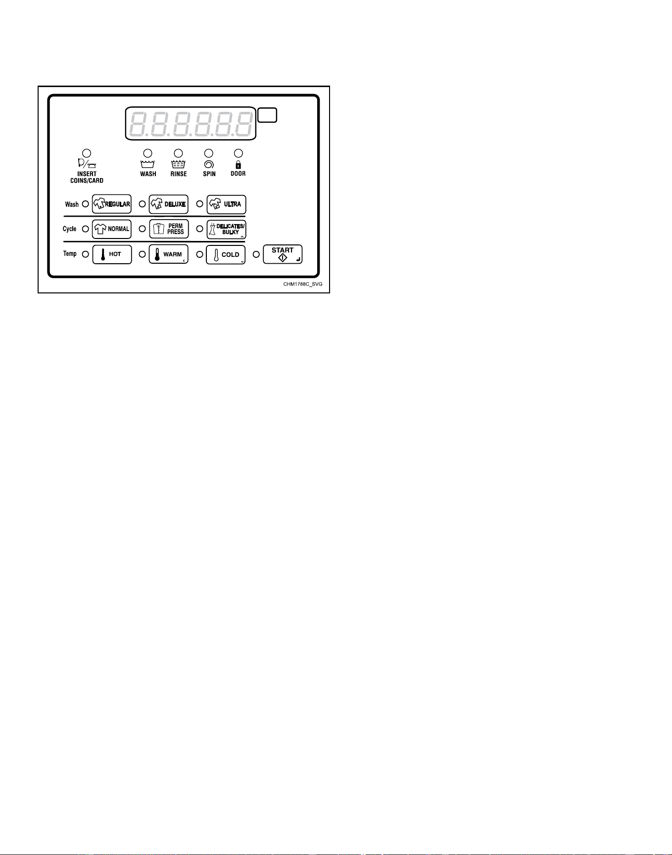
DCJ, SCH and SCT Models with N and W Controls
Figure 60
1. Press the Regular, Delux or Ultra keypad to choose the de-
sired soil level. The corresponding LED indicates the selec-
tion.
2. Press the Normal, Perminant Press or Delicates/Bulky keypad
to choose the desired cycle. The corresponding LED indicates
the selection.
3. Press the Hot, Warm or Cold keypad to choose the desired
temperature. The corresponding LED indicates the selection.
4. Insert coin(s) or card as necessary.
• If the machine is a coin operated unit, add coins. As each
coin is added, the vend counts down to the amount re-
maining.
• If the machine is a card operated unit, insert and remove
card per card system instructions.
• If the unit is interfaced to a central/remote pay system, go
to the central/remote pay console, make payment and se-
lect the machine and follow central/remote pay system in-
structions.
5. Add liquid and/or powder supplies to supply dispenser. Refer
to Table 44 .
a. Detergent:
• Liquid - Compartment 1 (prewash) + Compartment 3
• Powder - Compartment 1 (prewash) + Compartment 2
b. Bleach:
• Liquid - Compartment 3
• Powder - Compartment 2
c. Softener:
• Liquid - Compartment 4
6. Press the START (enter) keypad to select.
NOTE: Cycles can be changed anytime during the
first Fill Step. After the first Fill Step, all cycle key-
pad presses are ignored.
7.
When a cycle is complete, the control displays OPEN DOOR.
Operation
©
Copyright, Alliance Laundry Systems LLC -
DO NOT COPY or TRANSMIT
100 Part No. F8619501ENR4
Downloaded from www.ManualsFile.com manuals search engine
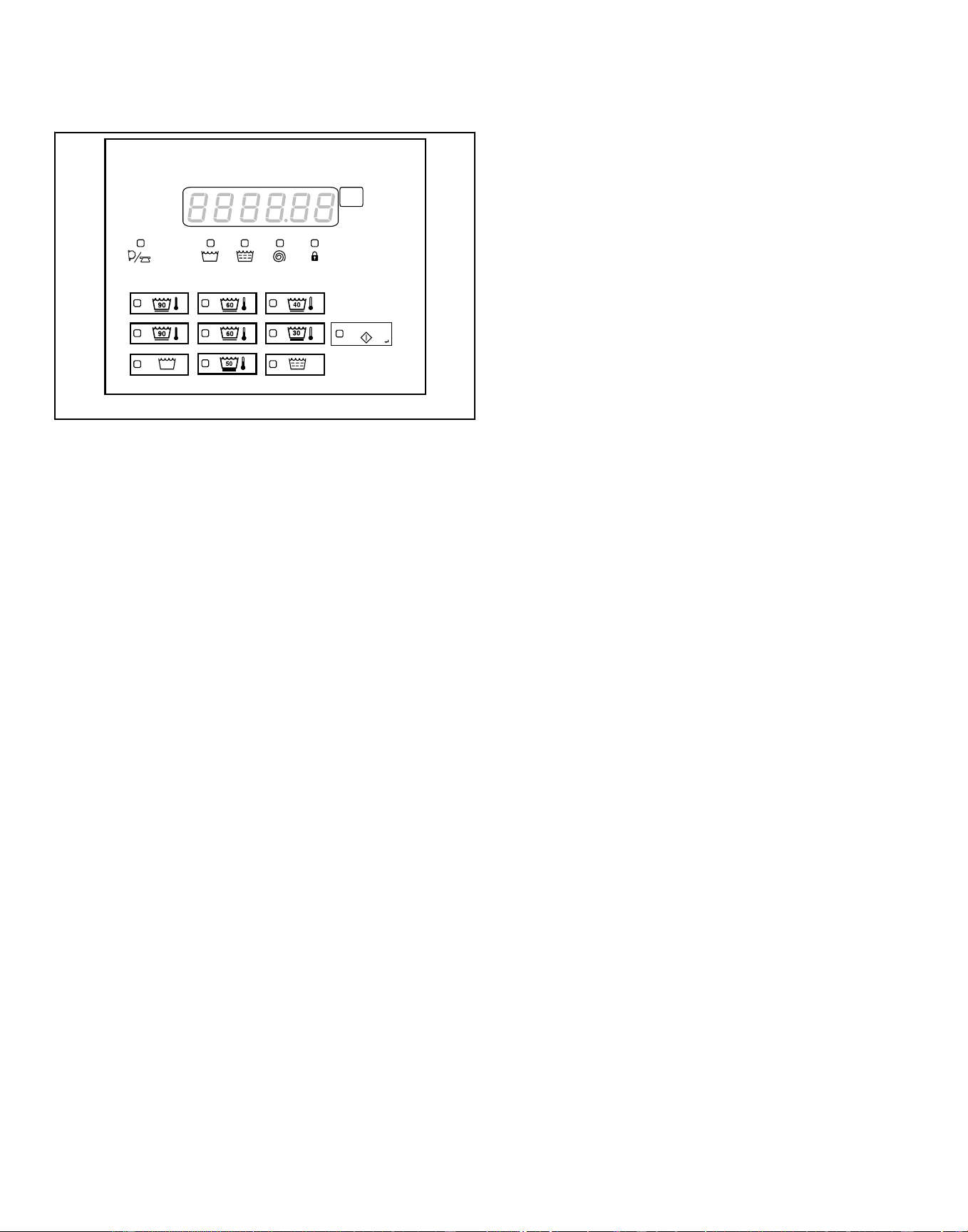
HCA, HCD, HCE, HCH, HCJ and HCU Models with
N and W Controls
CHM1795C_SVG
>
>
>
RinseWashInsert
Coins/Card
Spin Door
START
+
+
Figure 61
1. Press the Normal 90C, Normal 60C, Normal 40C, Perm Press
90C, Perm Press 60C, Gentle 30C or Perm Press 50C keypad
to choose the desired cycle/temperature. The corresponding
LED indicates the selection.
2. Press the Extra Wash and/or Extra Rinse keypads to add
modifiers to the cycle. The corresponding LEDs indicate the
added modifiers.
3. Insert coin(s) or card as necessary.
• If the machine is a coin operated unit, add coins. As each
coin is added, the vend counts down to the amount re-
maining.
• If the machine is a card operated unit, insert and remove
card per card system instructions.
• If the unit is interfaced to a central/remote pay system, go
to the central/remote pay console, make payment and se-
lect the machine and follow central/remote pay system in-
structions.
4. Add liquid and/or powder supplies to supply dispenser. Refer
to Table 44 .
a. Detergent:
• Liquid - Compartment 1 (prewash) + Compartment 3
• Powder - Compartment 1 (prewash) + Compartment 2
b. Bleach:
• Liquid - Compartment 3
• Powder - Compartment 2
c. Softener:
• Liquid - Compartment 4
5. Press the START (enter) keypad to select.
NOTE: Cycles can be changed anytime during the
first Fill Step. After the first Fill Step, all cycle key-
pad presses are ignored.
6.
When a cycle is complete, the control displays OPEN DOOR.
Operation
©
Copyright, Alliance Laundry Systems LLC -
DO NOT COPY or TRANSMIT
101 Part No. F8619501ENR4
Downloaded from www.ManualsFile.com manuals search engine
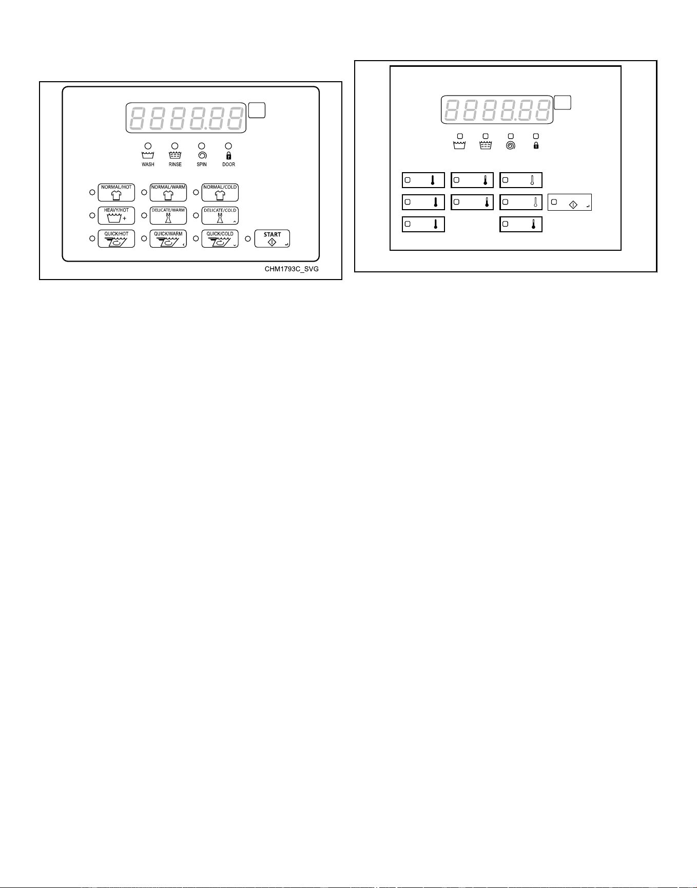
SCT Modles with Q Control
Figure 62
1. Press the Normal/Hot, Normal/Warm, Normal/Cold, Heavy/
Hot, Delicate/Warm, Delicate/Cold, Quick/Hot, Quick/Warm
or Quick/Cold keypad to select the desired cycle.
2. Insert coin(s) or card as necessary.
• If the machine is a coin operated unit, add coins. As each
coin is added, the vend counts down to the amount re-
maining.
• If the machine is a card operated unit, insert and remove
card per card system instructions.
• If the unit is interfaced to a central/remote pay system, go
to the central/remote pay console, make payment and se-
lect the machine and follow central/remote pay system in-
structions.
3. Add liquid and/or powder supplies to supply dispenser. Refer
to Table 44 .
a. Detergent:
• Liquid - Compartment 1 (prewash) + Compartment 3
• Powder - Compartment 1 (prewash) + Compartment 2
b. Bleach:
• Liquid - Compartment 3
• Powder - Compartment 2
c. Softener:
• Liquid - Compartment 4
4. Press the START (enter) keypad to select.
NOTE: Cycles cannot be changed anytime after the
machine is started.
5.
When a cycle is complete, the control displays OPEN DOOR.
HCT Models with Q Control
CHM1794C_SVG
RinseWash Spin Door
Hot Warm Cold
>
Heavy
Hot
Quick
Hot
Delicate
Warm
Delicate
Cold
START
>
>
Quick
Warm
Figure 63
1. Press the Hot, Warm, Cold, Heavy/Hot, Delicate/Warm, Deli-
cate/Cold, Quick/Hot or Quick/Warm keypad to choose the
desired cycle/temperature. The corresponding LED indicates
the selection.
2. Insert coin(s) or card as necessary.
• If the machine is a coin operated unit, add coins. As each
coin is added, the vend counts down to the amount re-
maining.
• If the machine is a card operated unit, insert and remove
card per card system instructions.
• If the unit is interfaced to a central/remote pay system, go
to the central/remote pay console, make payment and se-
lect the machine and follow central/remote pay system in-
structions.
3. Add liquid and/or powder supplies to supply dispenser. Refer
to Table 44 .
a. Detergent:
• Liquid - Compartment 1 (prewash) + Compartment 3
• Powder - Compartment 1 (prewash) + Compartment 2
b. Bleach:
• Liquid - Compartment 3
• Powder - Compartment 2
c. Softener:
• Liquid - Compartment 4
4. Press the START (enter) keypad to select.
NOTE: Cycles can be changed anytime during the
first Fill Step. After the first Fill Step, all cycle key-
pad presses are ignored.
5.
When a cycle is complete, the control displays OPEN DOOR.
Operation
©
Copyright, Alliance Laundry Systems LLC -
DO NOT COPY or TRANSMIT
102 Part No. F8619501ENR4
Downloaded from www.ManualsFile.com manuals search engine
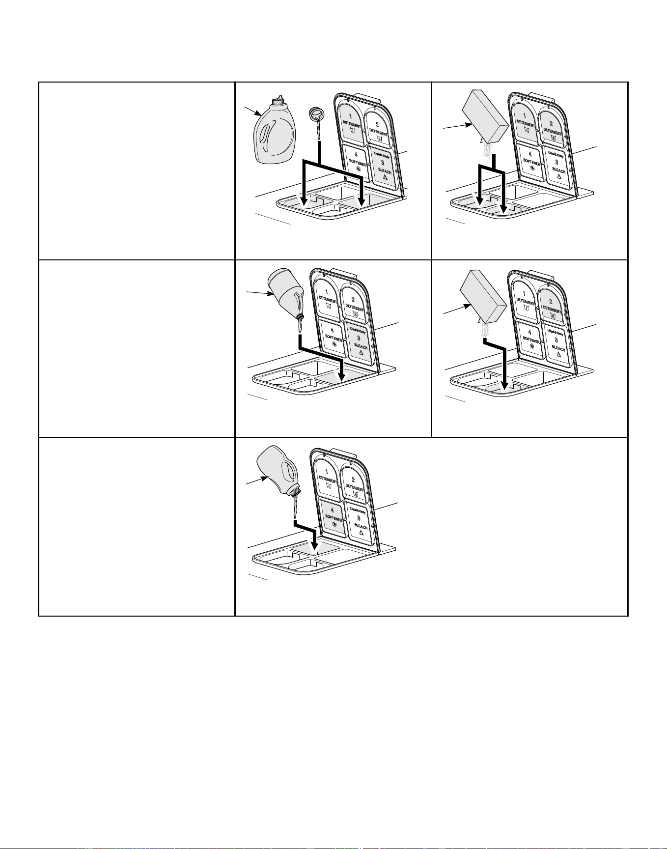
Adding Supplies
a. DETERGENT
CHM2228N_SVG
1
1. Liquid Detergent
CHM2227N_SVG
2
2. Powder Detergent
b. BLEACH
CHM2229N_SVG
3
3. Liquid Bleach
CHM2230N_SVG
4
4. Powder Bleach
c. SOFTENER
CHM2231N_SVG
5
5. Liquid Softener
Table 44
Operation
©
Copyright, Alliance Laundry Systems LLC -
DO NOT COPY or TRANSMIT
103 Part No. F8619501ENR4
Downloaded from www.ManualsFile.com manuals search engine
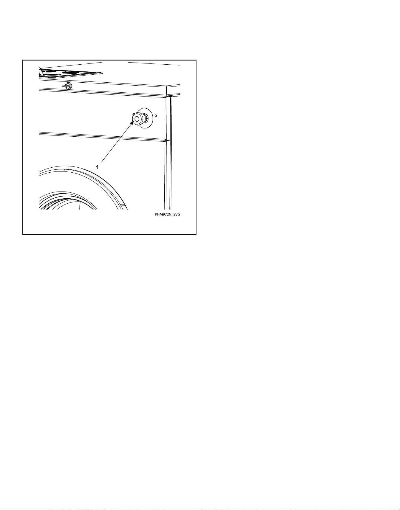
Emergency Stop Button (OPL Models
Only)
1. Emergency Stop Button
Figure 64
1. Press red emergency stop button to stop all action.
2. To restart the machine, pull red emergency stop button out
and press START (enter) on the control.
Operation
©
Copyright, Alliance Laundry Systems LLC -
DO NOT COPY or TRANSMIT
104 Part No. F8619501ENR4
Downloaded from www.ManualsFile.com manuals search engine
Maintenance
WARNING
Sharp edges can cause personal injury. Wear safety
glasses and gloves, use proper tools and provide
lighting when handling sheet metal parts.
W366R1
IMPORTANT: Replace all panels that are removed to
perform service and maintenance procedures. Do not
operate the machine with missing guards or with bro-
ken or missing parts. Do not bypass any safety devi-
ces.
Daily
IMPORTANT: Replace all panels that are removed to
perform maintenance procedures. Do not operate the
machine with missing guards or with broken or miss-
ing parts. Do not bypass any safety devices.
WARNING
Do not spray the machine with water. Short circuiting
and serious damage may result.
unique_73_Connect_42_note-1437506691659
IMPORTANT: Door lock should be checked daily to en-
sure proper operation. Also check that all safety and
instruction stickers are on the machine. Any missing or
illegible safety instructions stickers should be replaced
immediately.
Beginning of Day
1. Check door interlock before starting operation:
a. Attempt to start the machine with the door open. The ma-
chine should not start.
b. Close the door without locking it and start the machine.
The machine should not start.
c. Attempt to open the door while the cycle is in progress.
The door should not open.
If the door lock and interlock are not functioning properly, dis-
connect power and call a service technician.
2. Check the machine for leaks.
a. Start an unloaded cycle to fill the machine.
b. Verify that door and door gasket do not leak.
c. Verify that the drain valve is operating and that the drain
system is free from obstruction. If water does not leak out
during the first wash segment, the drain valve is closed
and functioning properly.
3. Inspect water inlet valve hose connections on the back of the
machine for leaks.
4. Inspect steam hose connections for leaks (if applicable).
5. On machines equipped with an automatic Chemical Supply
System, check all the hoses and hose connections for leaks or
visible signs of deterioration. Replace immediately if either
are present. Chemical leaks can cause damage to the ma-
chine’s components.
WARNING
To reduce the risk of electrical shock, serious in-
jury or death, disconnect the electrical power to
washer-extractor before examining the wiring.
W636
6. Verify that insulation is intact on all external wires and that all
connections are secure. If bare wire is evident, call a service
technician.
7. Ensure all panels and guards are properly installed.
End of Day
1. Inspect and clean the basket and door gasket of residual deter-
gent and all foreign matter.
2. Clean the door glass and between the door gasket and the
door with a damp cloth.
3. Clean automatic supply dispenser lid and general area with
mild detergent. Flush the dispenser with clean water.
4. Clean the machine’s top, front and side panels with all-pur-
pose cleaner. Rinse with clean water and dry.
IMPORTANT: Use only isopropyl alcohol to clean
graphic overlays. Never use ammonia-based, vine-
gar- based or acetone-based cleaners on graphic
overlays.
NOTE: Unload the machine promptly after each
completed cycle to prevent moisture buildup. Leave
loading door and dispenser lid open at the end of
each completed cycle to allow moisture to evapo-
rate.
5. Shut off water supply.
Monthly
NOTE: Disconnect power to the machine at its source
before performing the monthly maintenance proce-
dures.
1. Inspect the electrical connections for looseness. Tighten as re-
quired after disconnecting power.
Maintenance
©
Copyright, Alliance Laundry Systems LLC -
DO NOT COPY or TRANSMIT
105 Part No. F8619501ENR4
Downloaded from www.ManualsFile.com manuals search engine
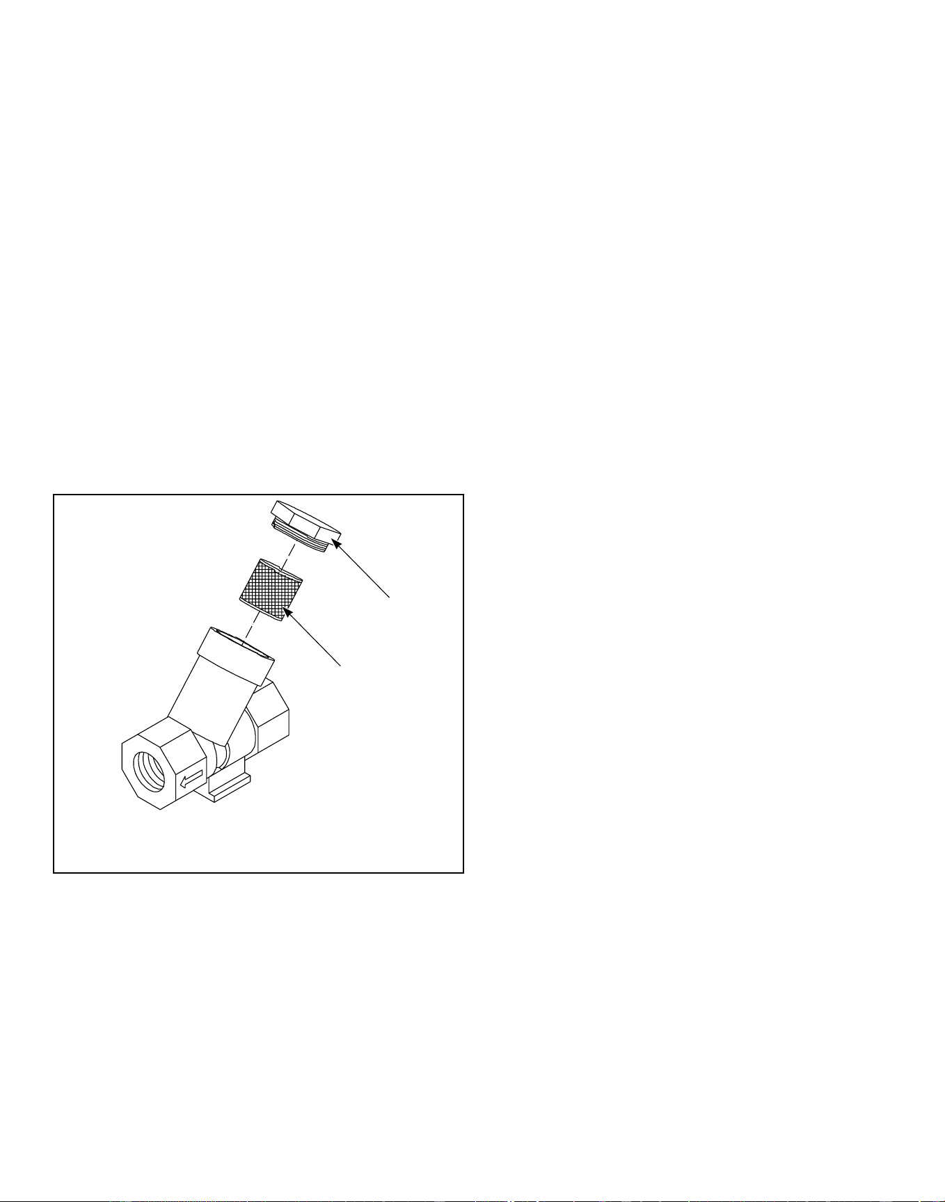
a. Verify that insulation is intact on all external wires and
that all connections are secure. If bare wire is evident, call
a service technician.
2. Clean inlet hose filter screens.
a. Turn water off and allow valve and water line to cool, if
necessary.
b. Unscrew inlet hose from the faucet and remove filter
screen.
c. Clean with soapy water and reinstall. Replace if worn or
damaged.
d. Repeat procedure with the filter located inside the valve at
the back of the machine.
NOTE: All filter screens should be replaced every
five years.
3. If applicable, clean the customer-supplied steam filter. Refer
to Figure 65 .
a. Turn off steam supply and allow time for the valve to cool.
b. Unscrew cap.
c. Remove element and clean.
d. Replace element and cap.
H042I_SVG
2
1
1. Cap
2. Steam Filter Element
Figure 65
4. For electric heat models only, inspect heating elements for ex-
cess debris by rotating basket to view them through its perfo-
rations. Remove drain valve hose to access and clear debris
with pliers. Replace element(s) if necessary.
NOTE: Lint buildup may take several months to oc-
cur. Inspect heating elements a minimum of every 6
months.
5. For 80 and 100 pound [36.3 and 45.4 kg] capacity models
only: Lubricate the barings each month or after every 200
hours of operation. Visually inspect grease line for air pock-
ets, purging air pockets as necessary.
The grease must have the following characteristics:
• NLGI Grade 2
• Lithium-based
• Water-insoluble
• Anti-rusting
• Anti-oxidizing
• Mechanically stable
The grease must have adequate base oil viscosity with one of the
following ratings:
• ISO VG 150 (709–871 SUS at 100°F [135–165 cSt at
40°C])
• ISO VG 220 (1047–1283 SUS at 100°F [198–242 cSt at
40°C])
• An SAE 40 rating is also acceptable as long as the cSt or
SUS values are within the specified ranges.
Pump the grease gun slowly, permitting only 2 strokes.
NOTE: Do not pump the grease gun until grease
comes out of the bearing housing. This can result in
over lubrication, causing damage to bearings and
seals.
Yearly
NOTE: Disconnect power to the machine at its source
before performing maintenance procedures.
1. Remove the front panel(s) and rear access panels and inspect
all hose, drain, and overflow connections/clamps for leaks. In-
spect all hoses for visible signs of deterioration. Replace as
necessary.
2. Inspect the belt for unusual wear, frayed edges, and improper
belt tension, replacing belts and/or adjusting tensioning ele-
ments as necessary.
NOTE: Belts must not be twisted and must be prop-
erly seated on pulleys. Belt must be centered on
basket pulley within .04 inches [1 mm].
a. Use the following procedures to determine if belt(s) re-
quire replacement or adjustment. Call a qualified service
technician in either case.
NOTE: Basket pulley must be rotated three (3)
full turns before assessing belt tension after ev-
ery adjustment.
• Frequency Gauge. Tighten eyebolt top nut until the
correct frequency (refer to Table 8 ) is obtained mid-
span. Torque jam nut to spring bracket to 20.6 ± 2 ft.-
lbs. Refer to Figure 66 .
Maintenance
©
Copyright, Alliance Laundry Systems LLC -
DO NOT COPY or TRANSMIT
106 Part No. F8619501ENR4
Downloaded from www.ManualsFile.com manuals search engine
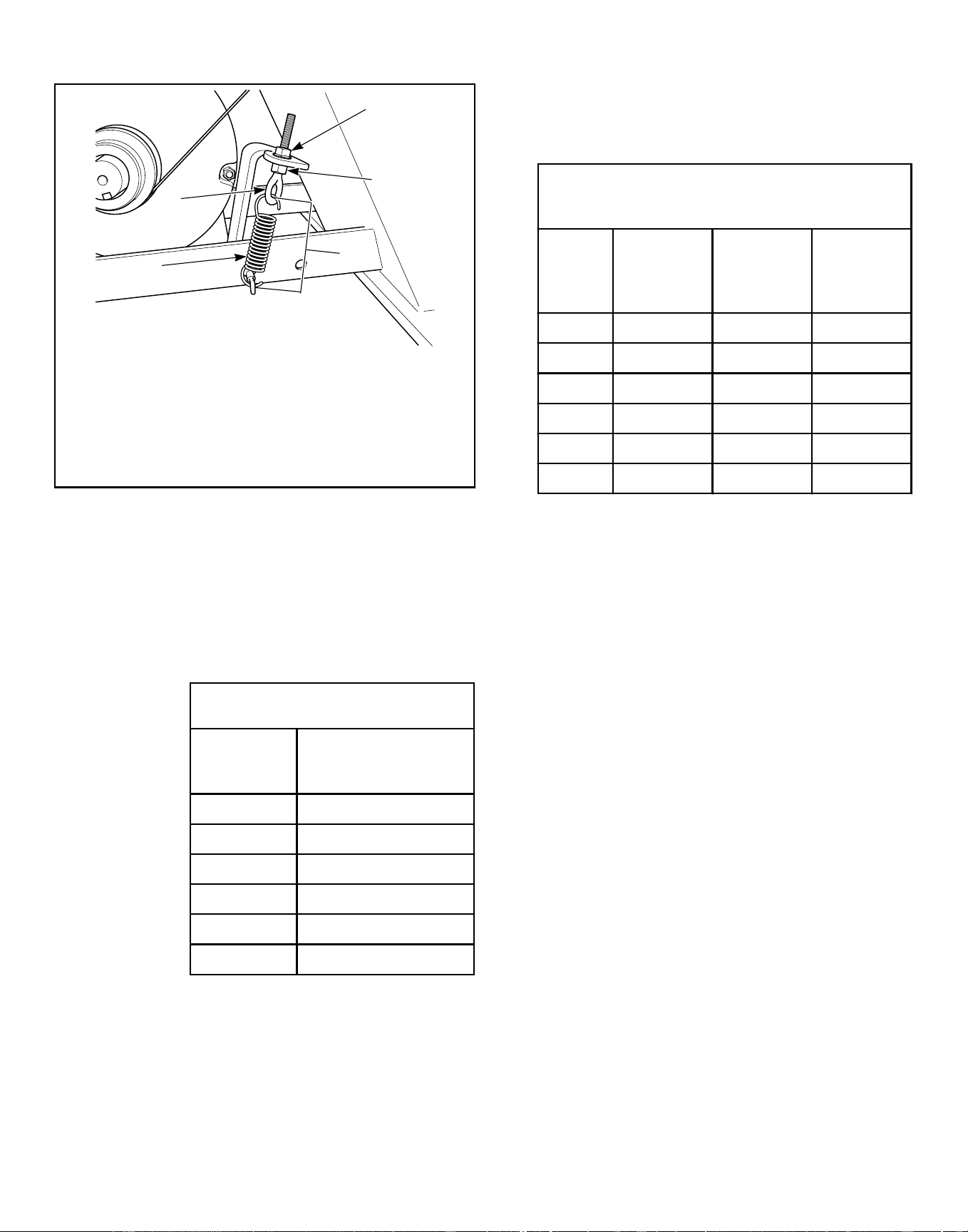
PHM963N_SVG
1
2
5
4
3
1. Top Nut
2. Jam Nut
3. Spring Length
4. Spring
5. Eyebolt
Figure 66
• Tension Gauge. Tighten eyebolt top nut until the prop-
er belt gauge (refer to Table 8 ) is obtained mid-span.
Torque jam nut to spring bracket to 20.6 ± 2 ft.-lbs.
Refer to Figure 66 .
• Spring Length. Tighten eyebolt top nut until the
spring measures the correct distance between the
hooks. Refer to Table 45 . Torque jam nut to spring
bracket to 20.6 ± 2 ft.-lbs. Refer to Figure 66 .
Spring Length, in. [mm]
Model
Distance Between
Hooks
20 (2 HP) 4-9/16 [116]
30 4-1/2 [114]
40 4-5/8 [117]
60 5-1/4 [133]
80 4-9/16 [116]
100 4-9/10 [124]
Table 45
• Maintain Tension During Belt Removal. If proper
tension is achieved, tape the jam nut in place and loos-
en eyebolt top nut to release the belt. Replace belt and
retighten eyebolt top nut back to jam nut position. Re-
fer to Figure 66 .
IMPORTANT: All torque joints must remain dry
(non-lubricated).
b. 20-60 Models: verify the belt is centered on the basket
pulley with in one (1) rib. 80-100 Models: verify the belt
is within the allowable distance of .04 inch [1 mm] be-
tween the belt and the edge of basket pulley.
Belt Tension by Frequency or Belt Tension
Gauge
Model
Frequen-
cy (Hz)
Belt Ten-
sion
(lbs.)
Tension
Gauge
(N)
20 88 ± 2 60.4 ± 6.1 269 ± 27
30 84 ± 2 63.2 ± 6.3 281 ± 28
40 75 ± 2 88.6 ± 8.8 394 ± 39
60 70 ± 2 100.2 ± 5.7 446 ± 25
80 102 ± 2 135 ± 5 601 ± 23
100 110 ± 2 158 ± 5 702 ± 23
Table 46
3. Remove any accumulated debris on or near the motor and
motor variable frequency drive heat sinks, if applicable.
4. If applicable, unlock or unscrew the top cover and inspect the
supply dispenser hoses and hose connections for visible signs
of deterioration. Replace hoses if worn or damaged.
NOTE: Hoses and other natural rubber parts deterio-
rate after extended use. Hoses may develop cracks,
blisters or material wear from the temperature and
constant high pressure they are subjected to.
5. Remove any dust from all electrical components, including
coin acceptors if applicable, with compressed air.
6. Inspect hardware for any loose nuts, bolts, screws.
a. Check the tightness of the motor spring and motor pulley
hardware. Also check that the eyebolt is tightened proper-
ly.
b. Tighten motor mounting bolt locknuts and bearing bolt
locknuts, if necessary.
c. Check the bearing mounting bolts to make sure they are
torqued properly. Refer to Table 47 .
Maintenance
©
Copyright, Alliance Laundry Systems LLC -
DO NOT COPY or TRANSMIT
107 Part No. F8619501ENR4
Downloaded from www.ManualsFile.com manuals search engine
Torque, ft-lbs.
Model Bearing Torque
20 All 41
30-40 All 101
60 All 201
80-100 All 357
Table 47
d. Tighten door hinges and fasteners, if necessary.
7. Ensure all panels and guards are properly reinstalled.
a. Verify that the drain motor shield is in place and secure, if
so equipped.
8. Run factory test, reference programming manual for proce-
dure details and components tested.
NOTE: Refer to the Programming Manual for proce-
dure details and components tested.
9. Inspect all painted surfaces for exposed metal. Replace or re-
paint if necessary.
• If bare metal is showing, paint with primer or solvent-
based paint.
• If rust appears, remove it with sandpaper or by chemical
means. Repaint with primer or solvent-based paint.
10. Torque anchor bolts and inspect grout for cracking.
NOTE: Refer to the Installation Manual for anchor
bolt specifications.
IMPORTANT: All torque joints must remain dry (non-
lubricated).
11. Every 5 years replace inlet hoses, hose screens, belt, and fan
filter (if applicable).
Care of Stainless Steel
• Remove dirt and grease with detergent and water. Thoroughly
rinse and dry after washing.
• Avoid contact with dissimilar metals to prevent galvanic cor-
rosion when salty or acidic solutions are present.
• Do not allow salty or acidic solutions to evaporate and dry on
stainless steel. Wipe clean of any residues.
• Rub in the direction of the polish lines or “grain” of the stain-
less steel to avoid scratch marks when using abrasive clean-
ers. Use stainless steel wool or soft, non-metal bristle brushes.
Do not use ordinary steel wool or steel brushes.
• If the stainless steel appears to be rusting, the source of the
rust may be an iron or steel part not made of stainless steel,
such as a nail or screw.
• Remove discoloration or heat tint from overheating by scour-
ing with a powder or by employing special chemical solu-
tions.
• Do not leave sterilizing solutions on stainless steel equipment
for prolonged periods of time.
• When an external chemical supply is used, ensure no siphon-
ing of chemicals occurs when the machine is not in use. High-
ly concentrated chemicals can cause severe damage to stain-
less steel and other components within the machine. Damage
of this kind is not covered by the manufacturer’s warranty.
Locate the pump and tubing below the machine’s injection
point to prevent siphoning of chemicals into the machine.
Maintenance
©
Copyright, Alliance Laundry Systems LLC -
DO NOT COPY or TRANSMIT
108 Part No. F8619501ENR4
Downloaded from www.ManualsFile.com manuals search engine
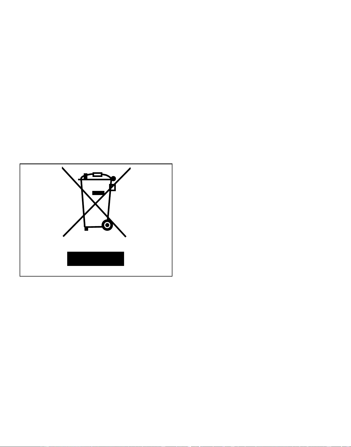
Disposal of Unit
This appliance is marked according to the European directive
2002/96/EC on Waste Electrical and Electronic Equipment
(WEEE).
This symbol on the product or on its packaging indicates that this
product shall not be treated as household waste. Refer to Figure
67 . Instead it shall be handed over to the applicable collection
point for the recycling of electrical and electronic equipment. En-
suring this product is disposed of correctly will help prevent po-
tential negative consequences for the environment and human
health which could otherwise be caused by inappropriate waste
handling of this product. The recycling of materials will help to
conserve natural resources. For more detailed information about
recycling of this product, please contact the local city office,
household waste disposal service, or the source from which the
product was purchased.
MIX1N_SVG
Figure 67
Disposal of Unit
©
Copyright, Alliance Laundry Systems LLC -
DO NOT COPY or TRANSMIT
109 Part No. F8619501ENR4
Downloaded from www.ManualsFile.com manuals search engine
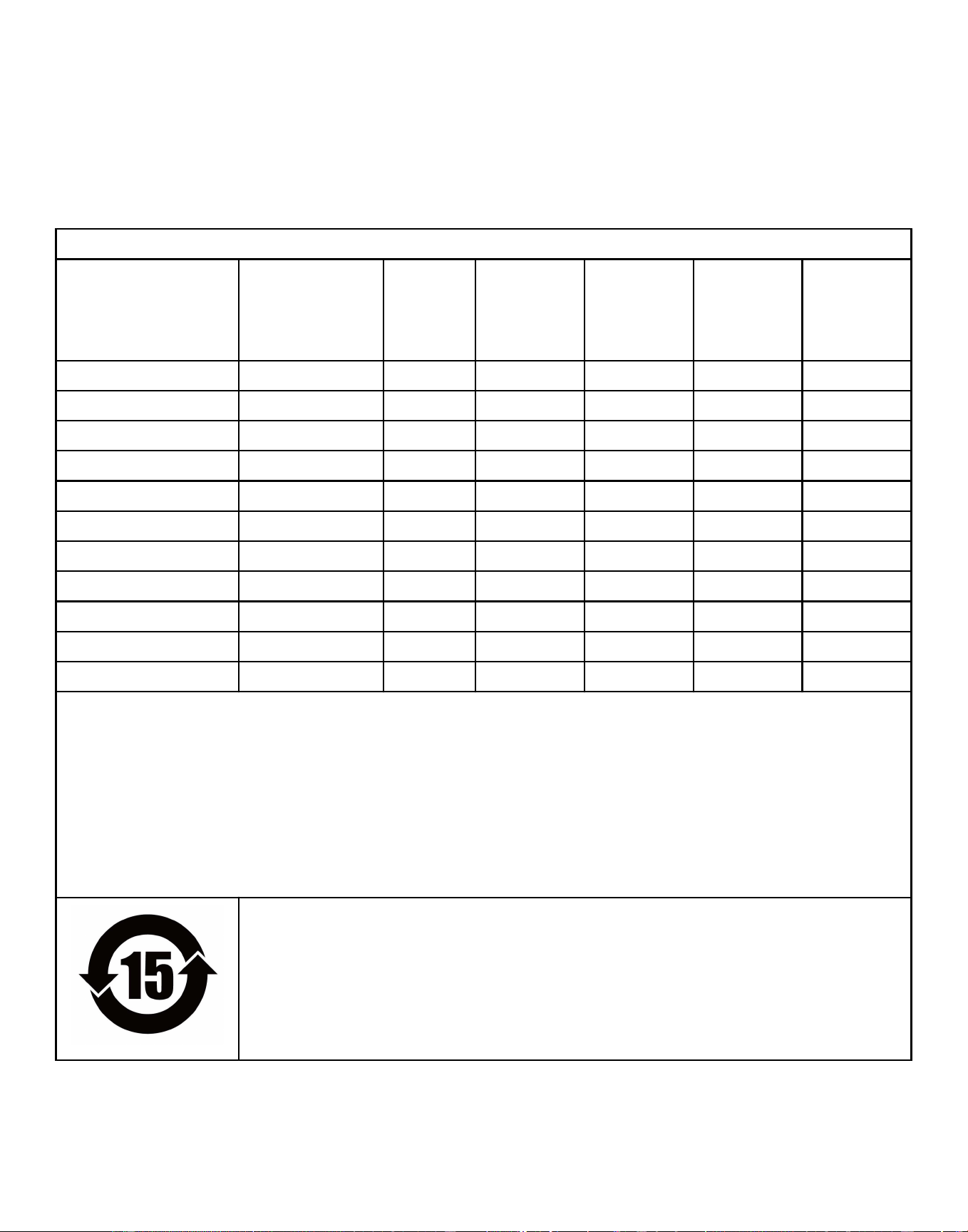
China Restriction of hazardous substances
(RoHS)
The Table of Hazardous Substances/Elements and their Content As required by China’s Management Methods for Restricted Use
of Hazardous Substances in Electrical and Electronic Products
Hazardous substances
Part Name Lead
(Pb)
Mercury
(Hg)
Cadmium
(Cd)
Hexavalent
Chromium
(CR[VI])
Polybromi-
nated biphen-
yls
(PBB)
Polybromi-
nated diphen-
yl ethers
(PBDE)
PCBs X O O O O O
Electromechanical Parts O O O O O O
Cables and Wires O O O O O O
Metal Parts O O O O O O
Plastic Parts O O O O O O
Batteries O O O O O O
Hoses and Tubing O O O O O O
Timing Belts O O O O O O
Insulation O O O O O O
Glass O O O O O O
Display O O O O O O
This table is prepared in accordance with the provisions of SJ/T-11364.
O: Indicates that the content of said hazardous substance in all of the homogenous materials in the component is within the limits
required by GB/T 26572.
X: Indicates that the content of said hazardous substance exceeds the limits required by GB/T 26572 in at least one homogenous
material in the component.
All parts named in this table with an “X” are in compliance with the European Union’s RoHS Legislation.
NOTE: The referenced Environmental Protection Use Period Marking was determined according to normal oper-
ating use conditions of the product such as temperature and humidity.
This product under normal use, durable years of environmental protection is 15 years.
China Restriction of hazardous substances (RoHS)
©
Copyright, Alliance Laundry Systems LLC -
DO NOT COPY or TRANSMIT
110 Part No. F8619501ENR4
Downloaded from www.ManualsFile.com manuals search engine