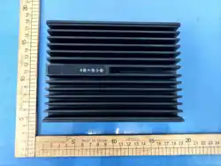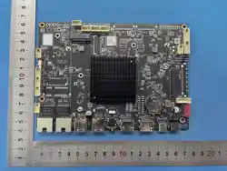

Embedded Intelligent Motherboard
AIoT3588
Version History
Version
Release Date
Author
Review
Notes
V2.0
2022-10-08
Zhang Linlin
/
Create this document.
V3.0
2025-01-24
Zhang Linlin
/
Replace product images, modify
interface descriptions, etc.
Approval for Release
Engineer Signature
Department Manager Signature
*This specification is made based on the existing information. There may be slight differences between the actual product and this
specification. The specific configuration information is subject to the sales contract. If you have any questions, please consult our
sales staff.
©2025 Nanjing Signway Technology Co.,Ltd. All rights reserved. Infringement must be investigated.

Table of Contents
1 Overview ................................................................................................................................................... 1
1.1 Introduction .....................................................................................................................................................1
2 Specification .............................................................................................................................................. 2
3 Profile ........................................................................................................................................................ 3
3.1 Profile ..............................................................................................................................................................3
3.2 Dimensions ......................................................................................................................................................5
4 Interfaces ................................................................................................................................................... 6
5 Electrical Performance .............................................................................................................................. 16

1
1 Overview
1.1 Introduction
The computing power motherboard AIoT3588 adopts the brand-new flagship chip RK3588 8-core CPU, quad
core Cortex-A76 and quad core Cortex-A55 NEON, Mali-G610 GPU. It is equipped with Android 12 system.
Enable more complex scenes with stronger performance, bringing a new round of intelligent upgrading. It is
applicable to vehicle mounted multi screen system, edge computing, multi screen/large screen display, industrial
and agricultural terminal equipment, security monitoring, ARM PC, AIoT intelligent terminal, intelligent NVR
and other application scenarios.
2
2 Specification
Specification
OS
Android 12
RAM
LPDDR4 4GB , 64 bit line width (default 4GB, optional 8GB/16GB, etc.)
Storage
eMMC 32GB (optional 16GB ~ 128GB)
CPU
RK3588, 4-core Cortex-A76 and 4-core Cortex-A55 NEON, up to 2.4GHz
GPU
ARM Mali-G610 MP4
Support OpenGL ES 1.1/2.0/3.2, OpenCL 2.2, Vulkan 1.2
Embedded 3D engine
NPU
Support 6T computing power
Media
Supports H.265/H.264/AV1/VP9/AVS2 video decoding, up to 8K@60FPS
Supports H.264/H.265 video encoding, up to 8K@30FPS
Video Input
32MP ISP, supports HDR and 3DNR
Supports 1 HDMI 2.0 input, up to 4K@60FPS
Network
Support 10/100/1000M adaptive Ethernet
WiFi, 802.11a/b/g/n/ac/ax, 1T1R, dual band 2.4G+5G
BT, BT5.0
Display Output
<Choose one of
two>
1 HDMI, HDMI Type-A, maximum support 8K@60Hz , output
1 LVDS, Double pin 2.0mm30P, maximum support 1080P@60Hz, output
Interface
1 TYPE-C (including USB2.0 OTG), 2 TYPE-A USB3.0 HOST, 4 PH2.0 USB2.0
HOST
3 UART serial port
1 TP interface
Support speaker interface, up to two 8 Ω 10W, dual channel speaker output
Support 1 MIC interface and 3.5 Headphones
1 NANO-SIM card holder
1 TF card holder, up to 128G
Dimension
170*120*12mm
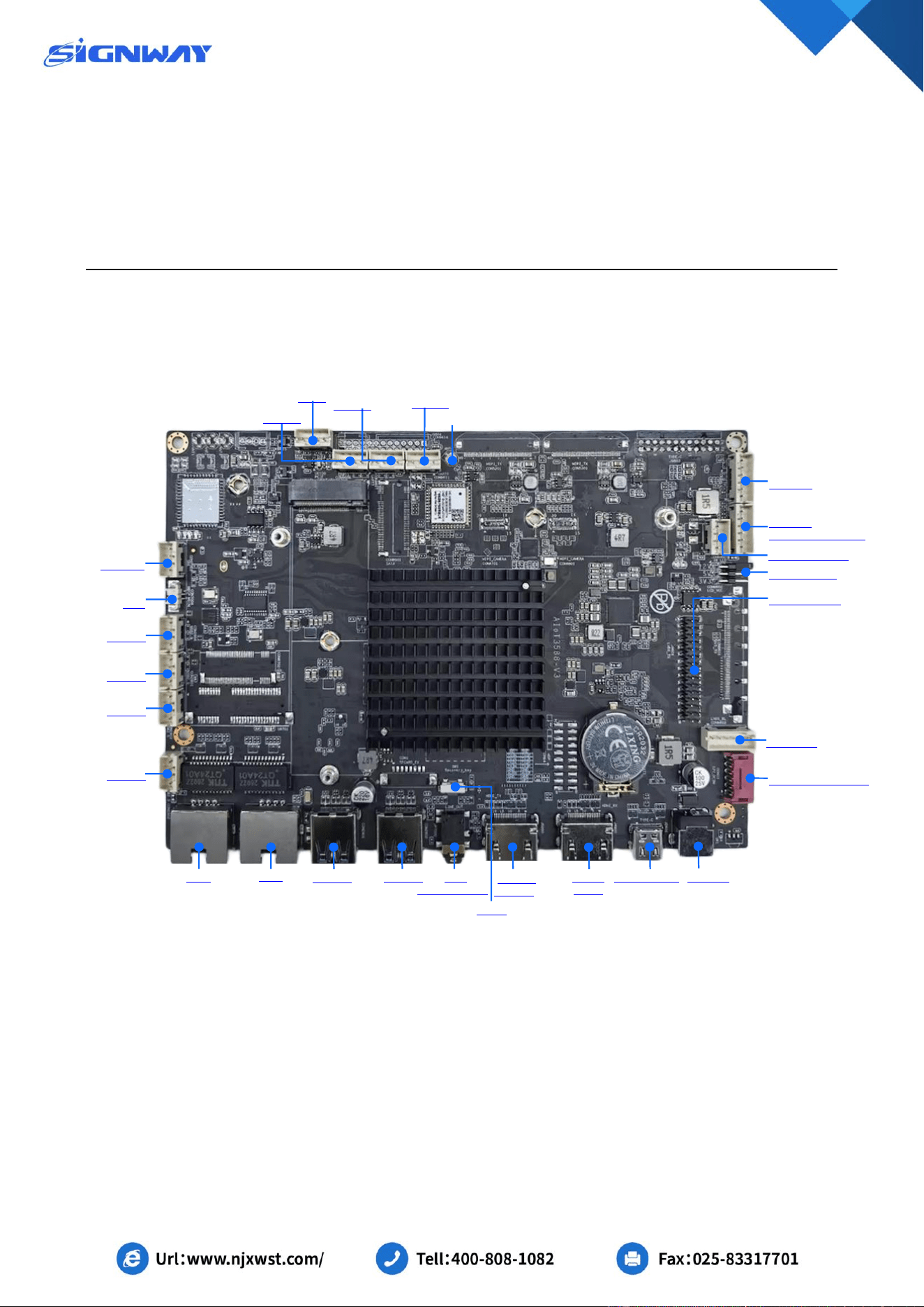
5
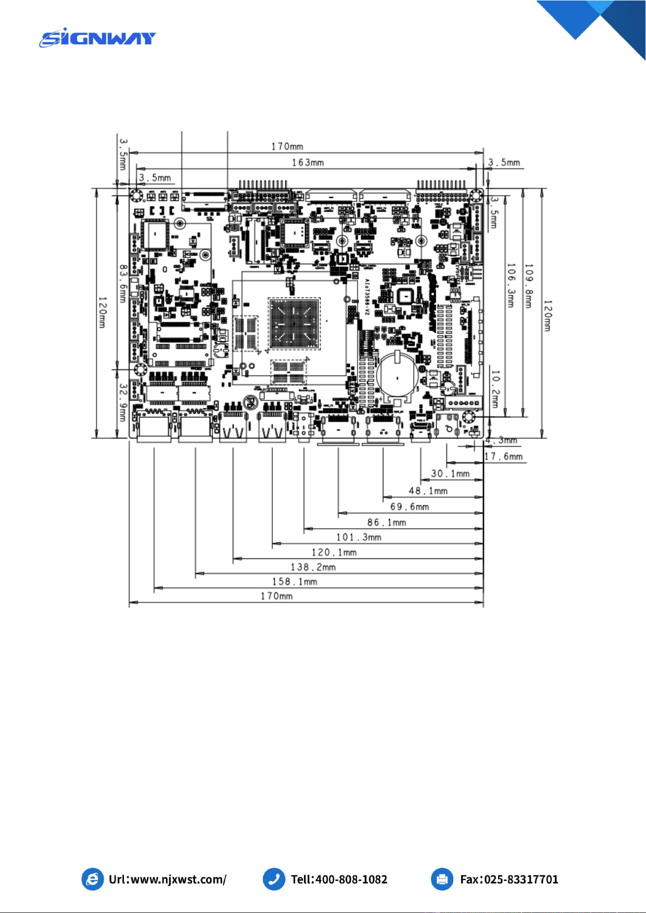
3.2 Dimensions
Length: 170mm, Width: 120mm, Front Max. Height: 8mm, Rear Max. Height: 2.5mm. Board thickness:
1.6mm, Screw Hole: Φ3.5mm
4 Interfaces
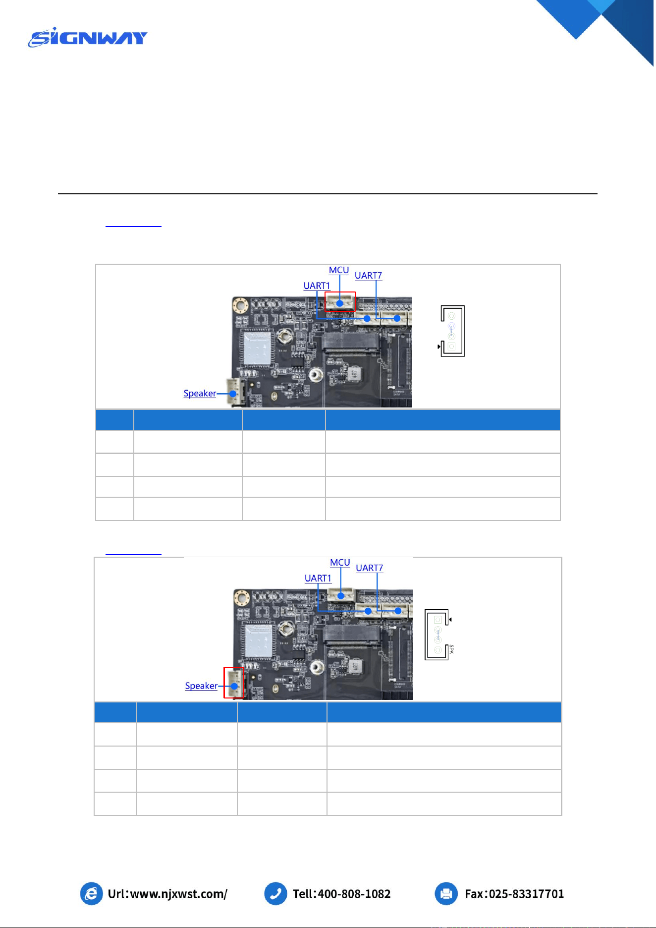
CON9401 MCU burning interfacee (PH2.0mm4P)
For internal R&D use only; intended for debugging; no external peripherals/equipment shall
be connected.
No.
Pin Name
Type
Description
1
3V3
Power
MCU burning power supply input,+3.3V
2
SWCLK
Input
Clock input
3
GND
Ground
Ground
4
SWDIO
Input/Output
DATA communication data
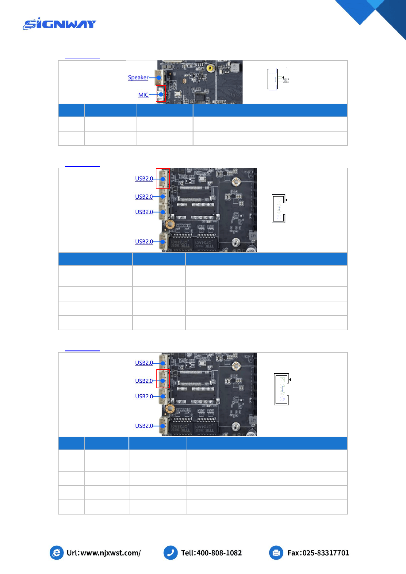
CON7003 Speaker (PH2.0mm4P)
No.
Pin Name
Type
Description
1
ROUT+
Output
R Positive
2
ROUT-
Output
R Negative
3
LOUT-
Output
L Negative
4
LOUT+
Output
L Positive
7
CON7004 MIC (PH1.25mm2P)
No.
Pin Name
Type
Description
1
MICP
Input
MIC +
2
MICN
Input
MIC-
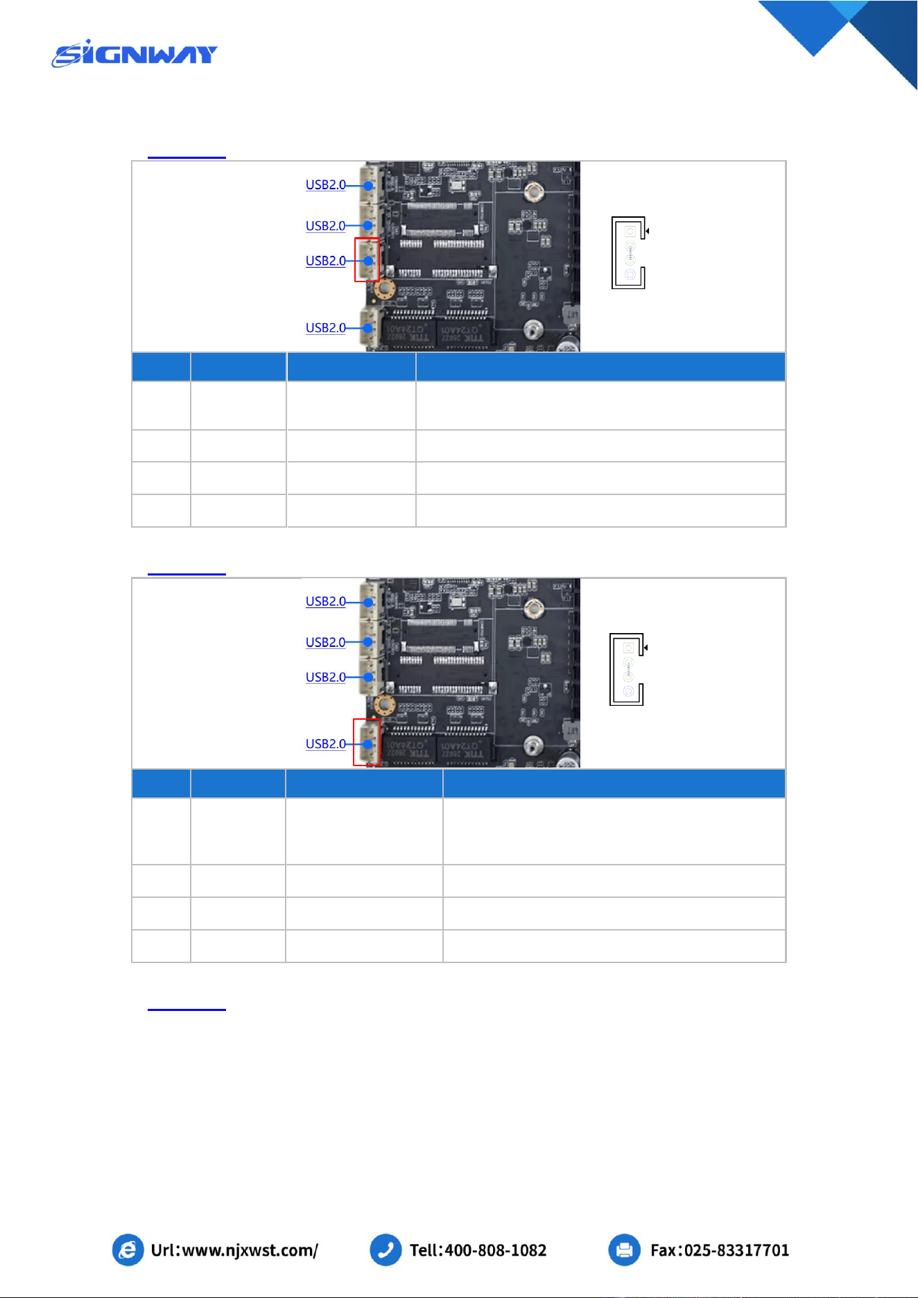
CON2804 USB2.0 interface(PH2.0mm4P)
No.
Pin Name
Type
Description
1
5V
Power output
Power output, +5V
Maximum output current 1A (shared with CON2801)
2
DM
Input / Output
D- signal line
3
DP
Input / Output
D+ signal line
4
GND
Ground
Ground
CON2801 USB2.0 interface (PH2.0mm4P)
No.
Pin Name
Type
Description
1
5V
Power output
Power output, +5V
Maximum output current 1A (shared with CON2804)
2
DM
Input / Output
D- signal line
3
DP
Input / Output
D+ signal line
4
GND
Ground
Ground
8
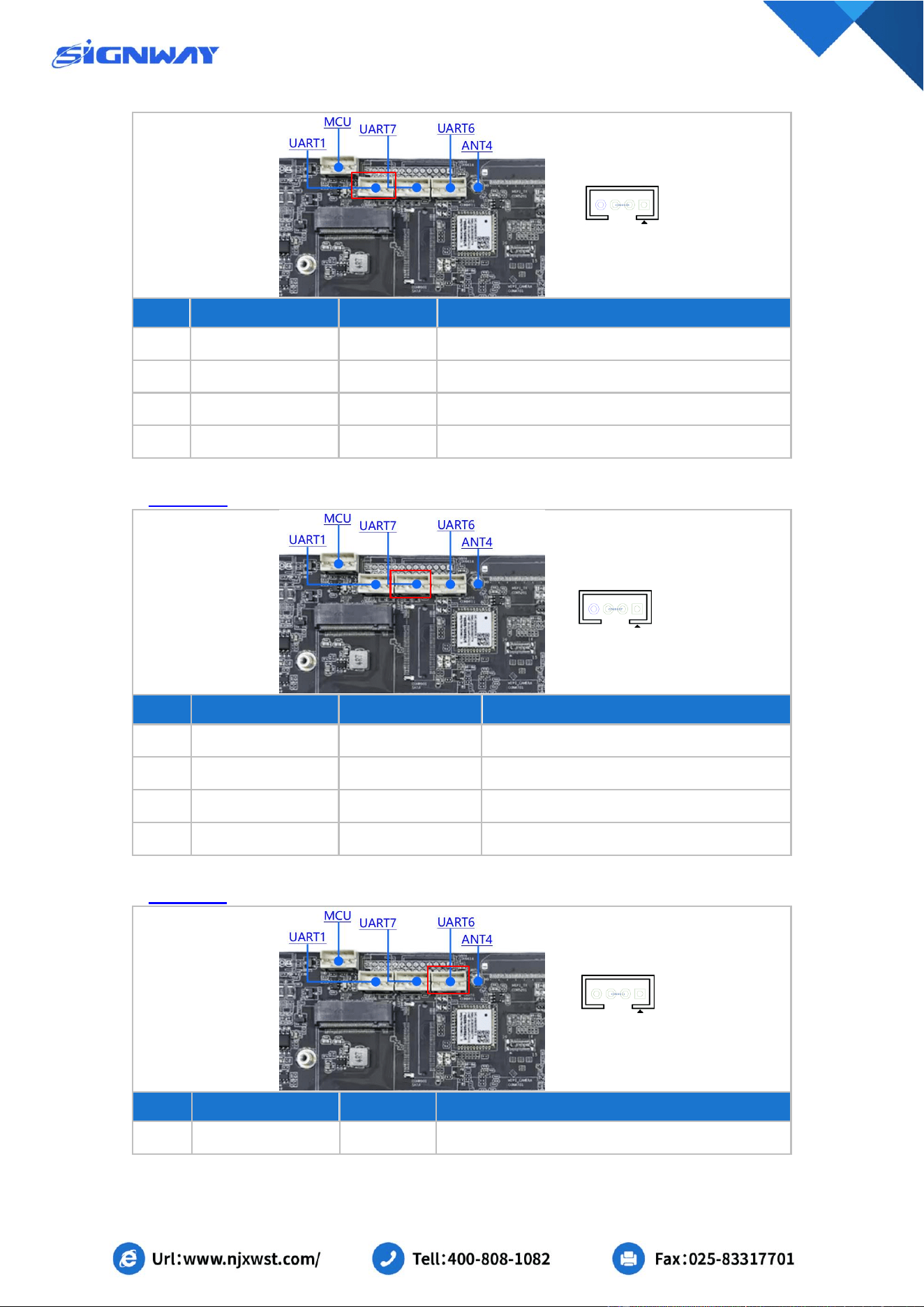
CON2803 USB2.0 interface (PH2.0mm4P)
No.
Pin Name
Type
Description
1
5V
Power output
Power output, +5V
Maximum output current 1A (shared with CON2802)
2
DM
Input / Output
D- signal line
3
DP
Input / Output
D+ signal line
4
GND
Ground
Ground
CON2802 USB2.0 interface (PH2.0mm4P)
No.
Pin Name
Type
Description
1
5V
Power output
Power output, +5V
Maximum output current 1A (shared with
CON2803)
2
DM
Input / Output
D- signal line
3
DP
Input / Output
D+ signal line
4
GND
Ground
Ground
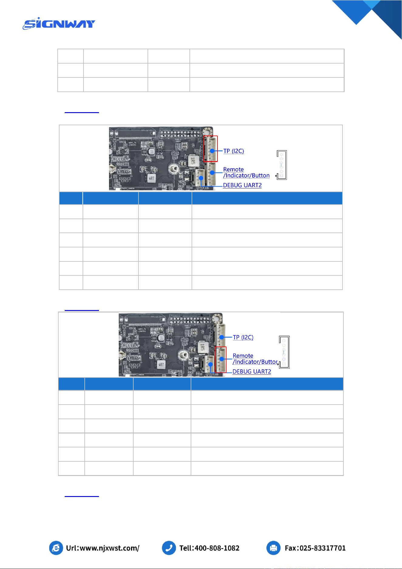
CON9606 UART1 interface (default RS232 mode, optional TTL) (PH2.0mm4P)
Same functionality as UART6 and UART7.
9
No.
Pin Name
Type
Description
1
5V
Output
Power output, +5V
2
TX1
Output
Serial port output, +3.3V
3
RX1
Input
Serial port input, +3.3V
4
GND
Ground
Ground
CON9607 UART7 interface (default RS232 mode, optional TTL) (PH2.0mm4P)
No.
Pin Name
Type
Description
1
5V
Power output
Power output, +5V
2
TX7
Output
Serial port output, +3.3V
3
RX7
Input
Serial port input, +3.3V
4
GND
Ground
Ground
CON9611 UART6 interface (default RS485 mode, optional TTL) (PH2.0mm4P)
No.
Pin Name
Type
Description
1
5V
Output
Power output, +5V
10
2
TX6
Output
RS48_ A (TTL mode, serial port output), +3.3V
3
RX6
Input
RS48_ B (TTL mode, serial port input), +3.3V
4
GND
Ground
Ground
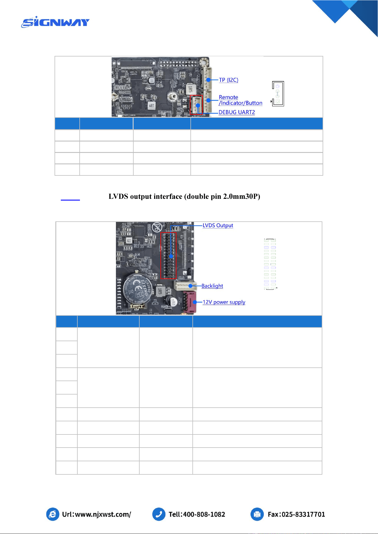
CON9613 Touch screen interface (PH2.0mm6P)
Used as a serial port, with functionality similar to that of UART6 and UART7.
No.
Pin Name
Type
Description
1
GND
Ground
Ground
2
I2C_SDA_TP
Input / Output
Touch screen I2C device data signal, +3.3V
3
I2C_SCL_TP
Output
Touch screen I2C device clock signal, +3.3V
4
TP_RST
Output
Reset signal output, +3.3V
5
TP_INT
Input
Interrupt signal input, +3.3V
6
VCC_3V3_S0
Output
Power output, +3.3V
CON9402 Remote control reception, work indicator, key interface (PH2.0mm6P)
No.
Pin Name
Type
Description
1
IR_EX
Input
Remote control reception signal input
2
GND
Ground
Ground
3
IR_VCC
Output
Remote head power supply +3.3V
4
RLED
Red light
Standby display, +3.3V
5
GLED
Green light
Work show, +3.3V
6
PWR_KEY
Input
External key Input
CON9307 UART interface(PH2.0mm6P)
For internal R&D use only; intended for debugging; no external peripherals/equipment shall
11
be connected.
No.
Pin Name
Type
Description
1
UART_5V
Output
Power output, +5V
2
URART2_TX
Output
Serial port output
3
URART2_RX
Input
Serial port input
4
GND
Ground
Ground
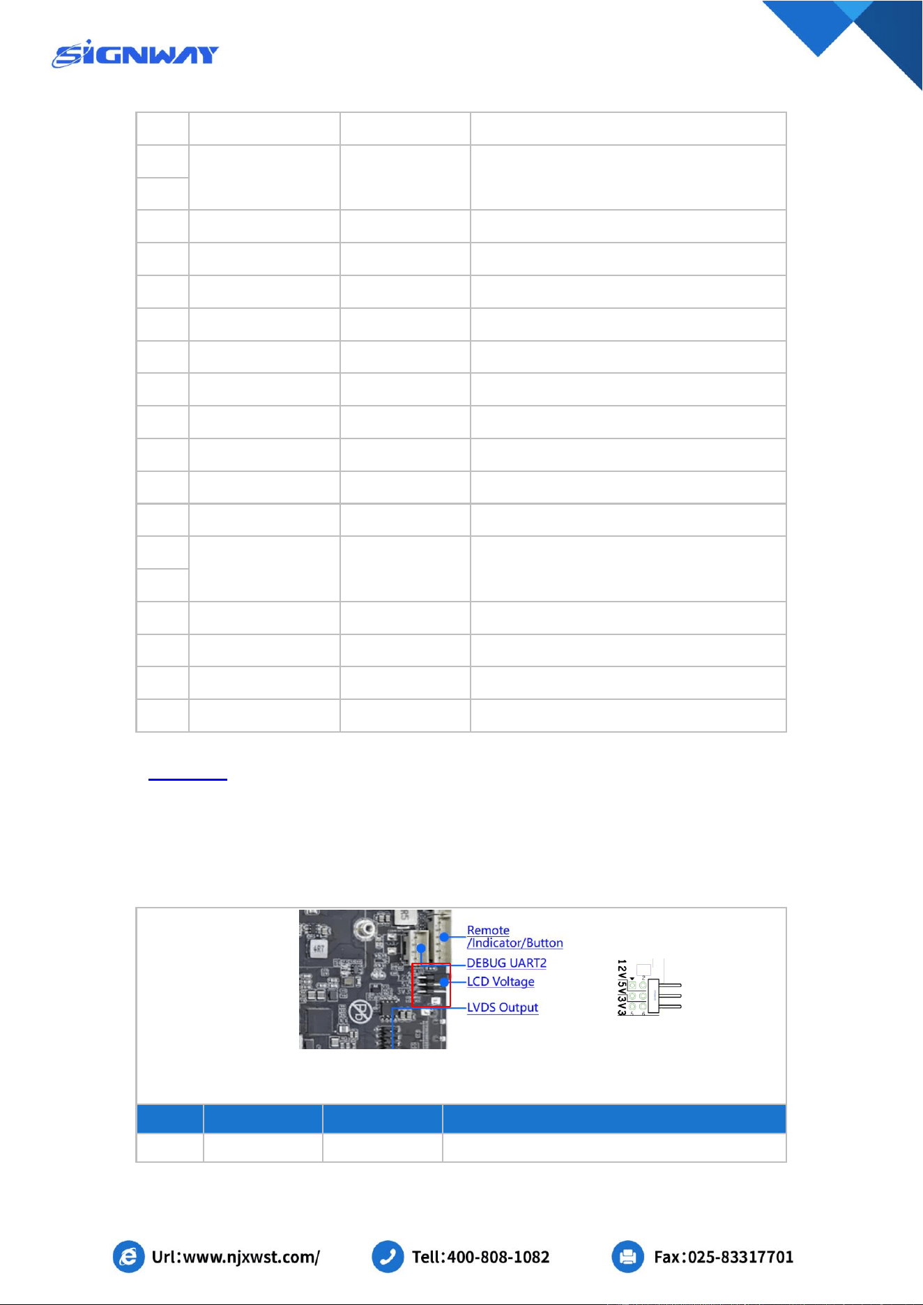
J9601
Backup interface
No.
Pin Name
Type
Description
1
VCC_PANEL
Power
LVDS screen power supply
2
3
4
GND
Ground
Ground
5
6
7
LVTX1_D0N
Output
Lane0- Output
8
LVTX1_D0P
Output
Lane0+ Output
9
LVTX1_D1N
Output
Lane1- Output
10
LVTX1_D1P
Output
Lane1+ Output
11
LVTX1_D2N
Output
Lane2- Output
12
12
LVTX1_D2P
Output
Lane2+ Output
13
GND
Ground
Ground
14
15
LVTX1_CLKN
Output
CLK1- Output
16
LVTX1_CLKP
Output
CLK1+ Output
17
LVTX1_D3N
Output
Lane3- Output
18
LVTX1_D3P
Output
Lane3+ Output
19
LVTX2_D0N
Output
Lane0- Output
20
LVTX2_D0P
Output
Lane0+ Output
21
LVTX2_D1N
Output
Lane1- Output
22
LVTX2_D1P
Output
Lane1+ Output
23
LVTX2_D2N
Output
Lane2- Output
24
LVTX2_D2P
Output
Lane2+ Output
25
GND
Ground
Ground
26
27
LV TX2_CLKN
Output
CLK2- Output
28
LVTX2_CLKP
Output
CLK2+ Output
29
LVTX2_D3N
Output
Lane3- Output
30
LVTX2_D3P
Output
Lane3+ Output
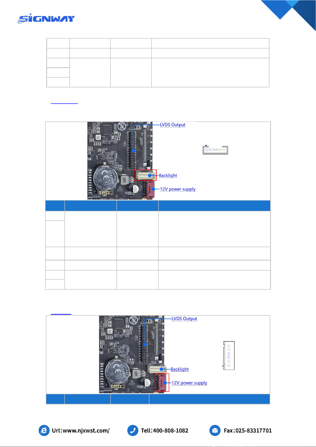
CON9602 LCD Voltage(double pin 2.0mm 6P)
CON24 corresponds to LCDVCC1 voltage selection on CON14/CON9601/J9601 socket
The screen voltage can be selected through the CON9602 jumper cap, and the screen power supply can be
selected to support 3.3V/5V/12V.
For example, if the LCD voltage used is 5V, then plug the two pins of 5V in the middle to jump out.
In the above picture, the jumper cap is used to select the screen power supply
CON9602 from top to bottom, in order: 12V / 5V / 3.3V
No.
Pin Name
Type
Description
1
12V
Power output
Power output, +12V
13
3
5V
Power output
Power output, +5V
5
3.3V
Power output
Power output, +3.3V
2
LCDVCC1
Power output
Screen pressure output
4
6
CON9603 Backlight interface (PH2.0mm6P)
Backup interface.
No.
Pin Name
Type
Description
1
+12V_NORMAL
Power output
Backlight power output, +12V, switchable
control, maximum controllable current 3A
Large-size multi-tube backlight panels with
operating current greater than 3A need to be
powered from the power supply separately
2
3
EN
Output
Backlight switch signal, 5V level, high and low
level can be configured
4
ADJ
Output
Backlight DIMMING Control
5
GND
Ground
Ground
6
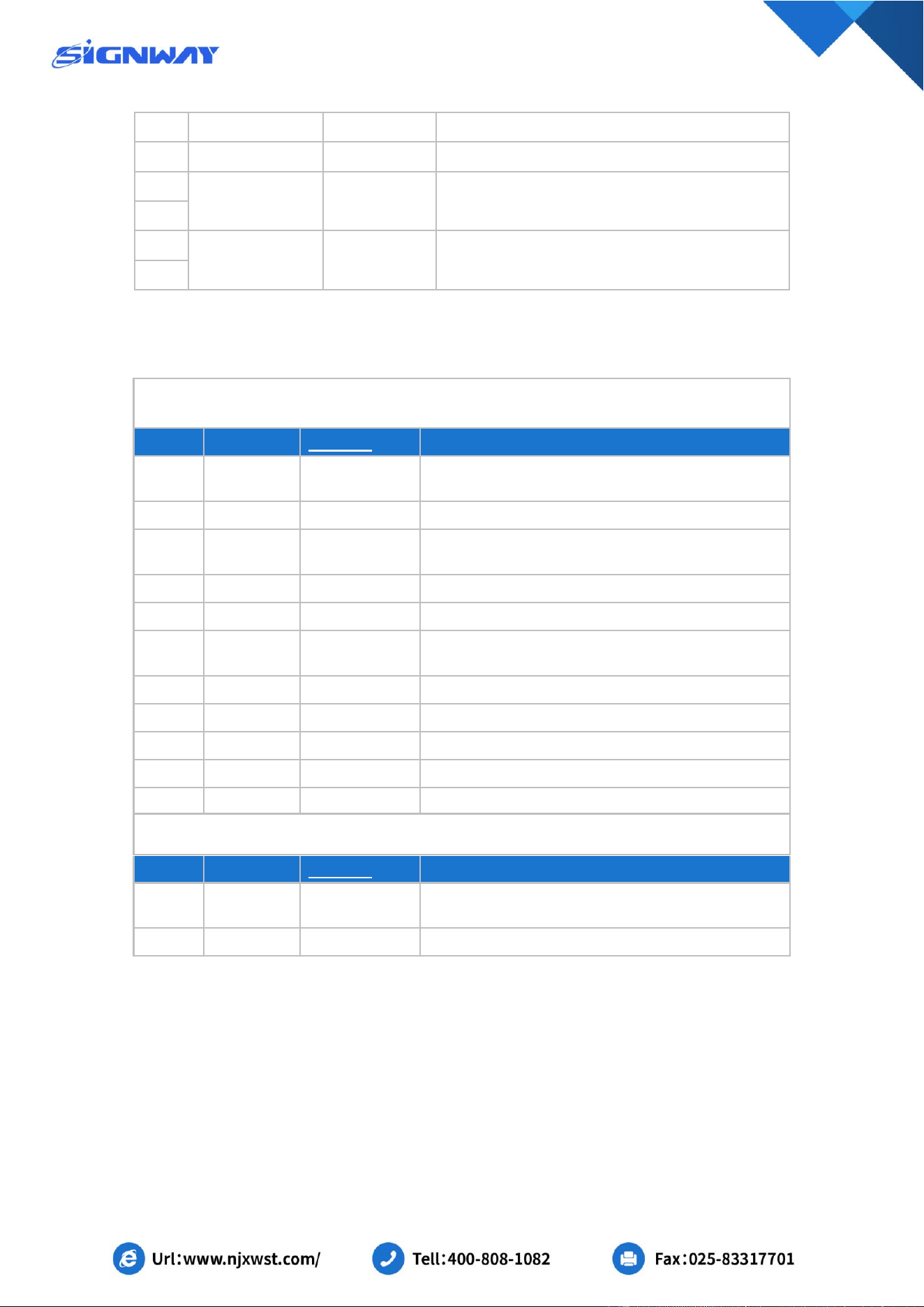
CON33 12V power input interface (PH2.0mm6P)
No.
Pin Name
Type
Description
14
1
STB
Output
Standby Power Control
2
5VSB
Input
Standby power, +5V
3
GND
Ground
Ground
4
5
VCC12V_DCIN
Power Input
Power input, +12V
6
Other Interface Description
Front View
No.
Positon
Interface
Description
1
ANT6201
ANT4
WIFI2.4G/5G/BT antenna interface, reserved,
optional
3
J2000
12V DC
Power interface, DC head, inner core 2.0mm
4
J2601
TYPE-C USB
TYPE-C interface, compatible with OTG function,
only supports 5V/1.5A power supply output
5
J4900
HDMI Input
HDMI input interface, max 4K@60HZ
6
J5000
HDMI Output
HDMI output interface, max 8K@60Hz
7
JP7000
3.5 headphone
Headphone interface, American standard interface,
audio L, audio R, GND, MIC signal in turn
8
CON2902
USB3.0
USB 3.0 interface
9
CON2901
USB3.0
USB 3.0 interface
10
JP6801
LAN
LAN
11
JP6701
LAN
LAN
13
SW1
Reset
Reset button
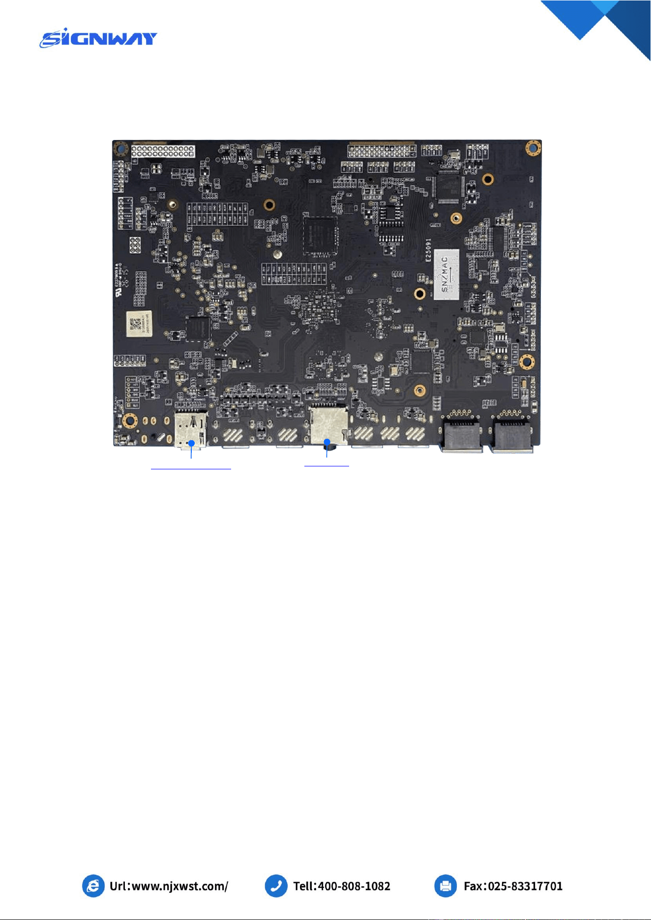
Back View
No.
Positon
Interface
Description
1
CON9604
NANO-SIM
card slot
NANO-SIM card slot
2
J4201
TF card slot
TF card slot
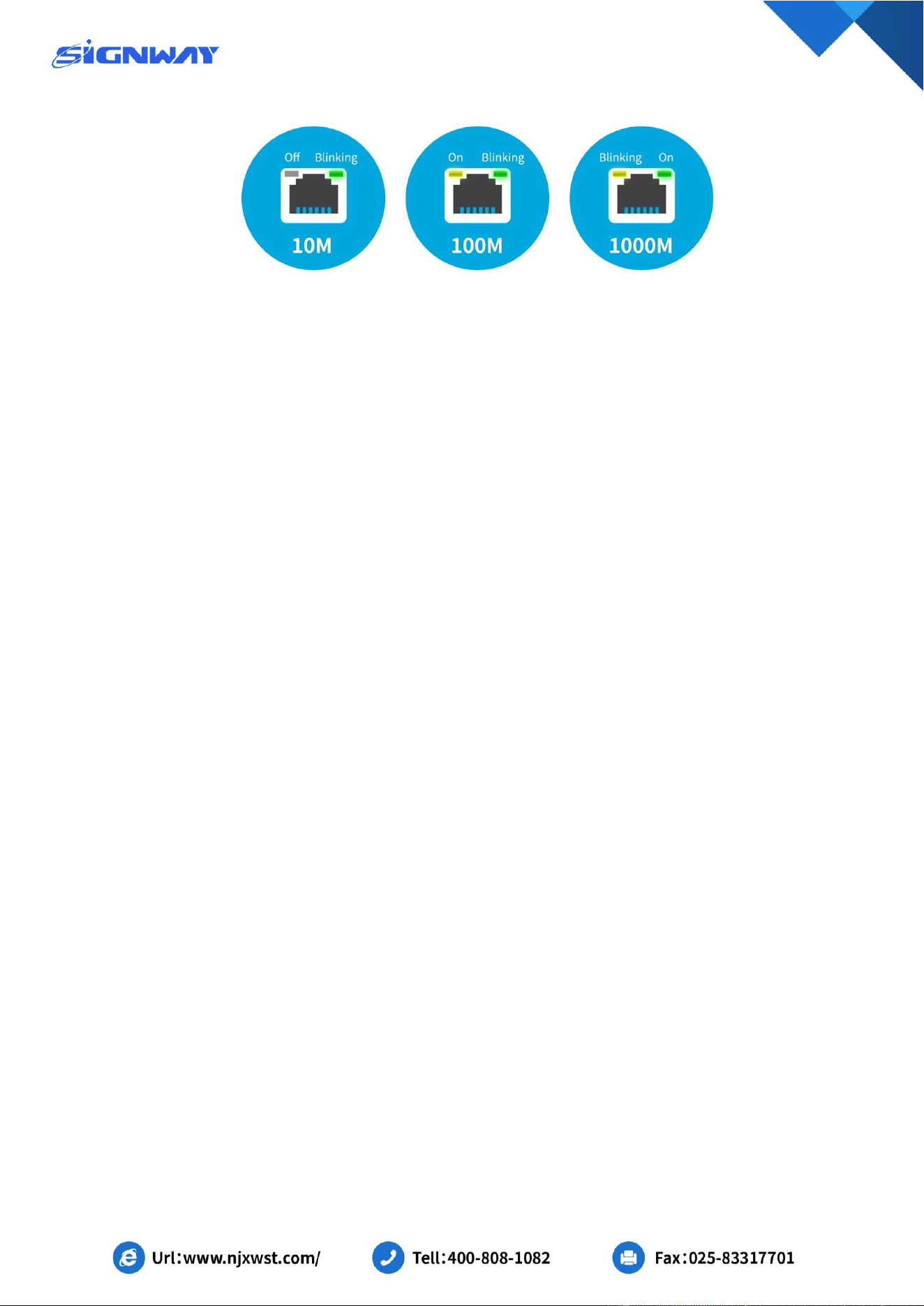
Schematic diagram of network port light status
15
16
5 Electrical Performance
Item
Min
Typical
Max
Power parameters
Voltage
10V
12V
14V
Ripple
--
150mV
--
Current
2A
3A
--
Supply Current
(no other peripherals
connected)
Working current
--
0.5A
--
Stand-by current
--
0.015A
--
Battery working current
--
0.5μA
--
Supply Current
(LVDS)
Working current
--
1.5A
3A
Stand-by current
--
0.015A
--
Supply Current
(HDMI)
Working current
--
0.8A
1.5A
Stand-by current
--
0.015A
--
Environment
Relative Humidity
30%
--
80%
Working Temperature
0℃
--
40℃
Storage Temperature
0℃
--
70℃

FCC Statement
Any Changes or modifications not expressly approved by the party responsible for compliance could
void the user’s authority to operate the equipment.
This device complies with part 15 of the FCC Rules. Operation is subject to the following two conditions:
(1) This device may not cause harmful interference, and
(2) This device must accept any interference received, including interference that may cause
undesired operation.
FCC Radiation Exposure Statement:
This equipment complies with FCC radiation exposure limits set forth for an uncontrolled
environment .This equipment should be installed and operated with minimum distance 20cm between
the radiator& your body.
Note : This equipment has been tested and found to comply with the limits for a Class B digital device,
pursuant to part 15 of the FCC Rules. These limits are designed to provide reasonable protection
against harmful interference in a residential installation. This equipment generates,uses and can
radiate radio frequency energy and, if not installed and used in accordance with the instructions, may
cause harmful interference to radio communications. However, there is no guarantee that interference
will not occur in a particular installation. If this equipment does cause harmful interference to radio or
television reception, which can be determined by turning the equipment off and on, the user is
encouraged to try to correct the interference by one or more of the following measures:
—Reorient or relocate the receiving antenna.
—Increase the separation between the equipment and receiver.
—Connect the equipment into an outlet on a circuit different from that to which the receiver is
connected.
—Consult the dealer or an experienced radio/TV technician for help.