EC
350
U
s
e
r
M
a
nu
al
_
V
.
G
e
n
e
r
al
I
ntro
d
u
c
t
i
on
.
I
ntro
d
u
c
t
i
on
.
P
ro
d
u
c
t
F
ea
tur
e
s
..
P
ro
ce
ssor
..
E
t
he
rn
e
t
..
P
e
r
i
p
he
r
al
&
I
/
O
..
I
nt
e
rn
al
S
yst
e
m
I
nt
e
r
face
s
.
M
echa
n
ical
S
p
ecifica
t
i
ons
.
E
lec
tr
ical
S
p
ecifica
t
i
ons
.
E
nv
i
ronm
e
nt
al
S
p
ecifica
t
i
ons
.
S
yst
e
m
I
nt
e
r
face
I
n
f
orm
a
t
i
on
.
1
I
nt
e
r
face
s
.
1
..
P
ow
e
r
I
n
dica
tor
.
1
.
S
yst
e
m
S
t
a
tus
LED
.
1
.
S
e
r
ial
P
ort
.
1
.
US
B
.
G
e
n
.
1
.
HDMI
.
.
1
.
E
t
he
rn
e
t
(
W
AN
/
LAN
)
.
1
.
S
MA
.
1
.
G
roun
di
n
g
C
onn
ec
t
i
on
.
1
.
DC
-
IN C
onn
ec
tor
.
1
.
R
ec
ov
e
ry
B
utton
.
1
.
R
e
s
e
t
B
utton
.
1
.
US
B
.
T
yp
e
-
C
.
1
.
T
F C
a
r
d
.
1
.
S
IM C
a
r
d
S
l
ot
.
1
.
CAN FD
.
1
.
D
igi
t
al
O
utputs
.
1
.
D
igi
t
al
I
nputs
.
1
.
RS
-
P
u
ll
-
up
/
d
own
D
i
p
S
w
i
t
che
s
.
1
.
GM
S
L
.
.
1
.
L
i
n
e
out
.
1
.
M
ic
rop
h
on
e
I
nst
alla
t
i
on
.
R
ail
M
ount
i
n
g
I
nst
alla
t
i
on
.
W
all
-
mount
ed
I
nst
alla
t
i
on
G
e
tt
i
n
g
S
t
a
rt
ed
.
C
onn
ec
t
i
n
g
to
E
qu
i
pm
e
nt
..
C
onn
ec
t
i
n
g
D
e
v
ice
v
ia
HDMI
...
C
onn
ec
t
i
n
g
HDMI
a
n
d
P
e
r
i
p
he
r
al
s
...
L
o
ggi
n
g
E
qu
i
pm
e
nt
..
C
onn
ec
t
i
n
g
v
ia
SS
H
...
C
onn
ec
t
i
n
g
to
t
he
N
e
twor
k
...
A
cce
ss
to
E
qu
i
pm
e
nt
.
V
e
rs
i
on
Q
u
e
ry
.
U
s
e
r
M
a
n
age
m
e
nt
..
C
r
ea
t
i
n
g
U
s
e
rs
..
D
ele
t
e
U
s
e
rs
..
D
i
s
able
a
n
d
E
n
able
U
s
e
rs
..
A
d
v
a
n
ced
E
xt
e
ns
i
on
o
f
U
s
e
r
M
a
n
age
m
e
nt
.
N
e
twor
k
S
e
tt
i
n
g
s
..
E
t
he
rn
e
t
S
e
tt
i
n
g
s
...
S
e
tt
i
n
g
s
M
a
n
age
m
e
nt
...
O
n
/
O
ff
M
a
n
age
m
e
nt
...
S
t
a
t
ic
C
on
fig
ur
a
t
i
on
....
D
yn
a
m
ic
C
on
fig
ur
a
t
i
on
..
W
i
-
F
i
S
e
tt
i
n
g
s
...
S
e
tt
i
n
g
s
M
a
n
age
m
e
nt

...
O
n
/
O
ff
M
a
n
age
m
e
nt
...
S
ca
nn
i
n
g
...
C
onn
ec
t
i
on
..
C
ell
u
la
r
N
e
twor
k
S
e
tt
i
n
g
s
...
C
on
fig
ur
i
n
g
C
ell
u
la
r
ECM M
o
de
...
S
w
i
t
chi
n
g
S
IM C
a
r
d
..
CAN FD
S
e
tt
i
n
g
s
..
B
l
u
e
toot
h
S
e
tt
i
n
g
s
...
S
e
tt
i
n
g
s
M
a
n
age
m
e
nt
...
O
n
/
O
ff
M
a
n
age
m
e
nt
...
B
l
u
e
toot
h
C
onn
ec
t
i
on
..
N
e
twor
k
S
e
tt
i
n
g
s
A
d
v
a
n
ced
E
xt
e
ns
i
ons
.
T
i
m
e
S
e
tt
i
n
g
s
..
S
e
tt
i
n
g
t
he
T
i
m
e
Z
on
e
..
A
dj
ust
i
n
g
t
he
T
i
m
e
.
P
e
r
i
p
he
r
al
C
on
fig
ur
a
t
i
on
..
S
e
r
ial
P
ort
M
a
n
age
m
e
nt
..
D
igi
t
al
i
nput
/
output
M
a
n
age
m
e
nt
.
A
d
v
a
n
ced
.
S
yst
e
m
U
p
da
t
e
s
.
S
yst
e
m
R
e
s
e
t
..
R
ec
ov
e
ry
flick
sw
i
t
ch
r
e
s
e
t
..
C
omm
a
n
d
R
e
s
e
t
.
S
ec
ur
i
ty
(
TP
M
.)
.
P
ro
g
r
a
mm
i
n
g
G
u
ide
EC5350 Series AI Edge Computer
User Manual
Version 1.0, September 2024
www.inhand.com

The software described in this manual is according to the license agreement, can only be
used in accordance with the terms of the agreement.
Copyright Notice
©
2024 InHand Networks All rights reserved.
Trademarks
The InHand logo is a registered trademark of InHand Networks.
All other trademarks or registered trademarks in this manual belong to their respective
manufacturers.
Disclaimer
The company reserves the right to change this manual, and the products are subject to
subsequent changes without prior notice. 9. We shall not be responsible for any direct,
indirect, intentional or unintentional damage or hidden trouble caused by improper
installation or use.
The EC5350 comes pre-integrated with NVIDIA
®
Jetson Orin NX
™
or Orin Nano
™
, making
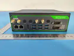
it ideal for industrial AI applications.The EC5350 design includes 2 Gigabit LAN ports, 1
HDMI video display, 6 external USB 3.2 ports, 2xRS-232/RS- 422/RS-485, 1 power
indicator, 1 system status light, 2 GMSL video interfaces, 4 DI, 4 DO, 1 CAN FD, 2 SIM card
slots, 1 USB Type C for system burn-in, 1 TF card slot, 1 reboot (hardware watchdog
1 General Introduction
1.1 Introduction
2 x 10 / 100 / 1000 Mbps
2 x RS-232/422/485 switchable serial interfaces with DB9 connectors
4 x DI,
Optocoupler isolation, supporting dry and wet nodes.
4 x DO,
Optocoupler isolation,
supporting 60 VDC sink voltage, 1.3 A max sink current
2 x USB 3.2 with
≤
15W drive capacity each
4 x USB 3.2 with
≤
4.5W drive capacity each
1 x USB 2.0, Type-C for system restore only
1 x HDMI 2.0 with maximum resolution of 3840 x 2160 @60Hz
2 x SIM card slots, supporting 1.8/3V SIM/UIM cards, built-in 15KV ESD protection, uses
standard SIM cards
2 x SMA antennas for cellular modules,2 x PR-SMA antennas Wi-Fi/BT modules
2 x LEDs, 1 for power indication, 1 for system status indication
1 x Micro-SD card slot for Micro-SD card expansion
1 x CAN FD up to 5Mbps
2 x flick switch buttons, 1 for reboot (enable/disable hardware watchdog), 1 for system
restore
2 x GMSL 2.0 FAKRA connectors
1 x MIC, 3.5mm microphone audio jack
1 x Audio, 3.5mm line-out
1.2.1 Ethernet
1.2.2 Peripheral & I/O
enable) button, 1 restore mode button, and 1 linear output connector and microphone
connector.
1.2 Product Features
1 x Trusted Platform Module, TPM 2.0
1 x NVME SSD
1 x Wi-Fi, supporting Wi-Fi 5
1 x Cellular module with 4G support
1 x RTC,
powered by a button cell battery
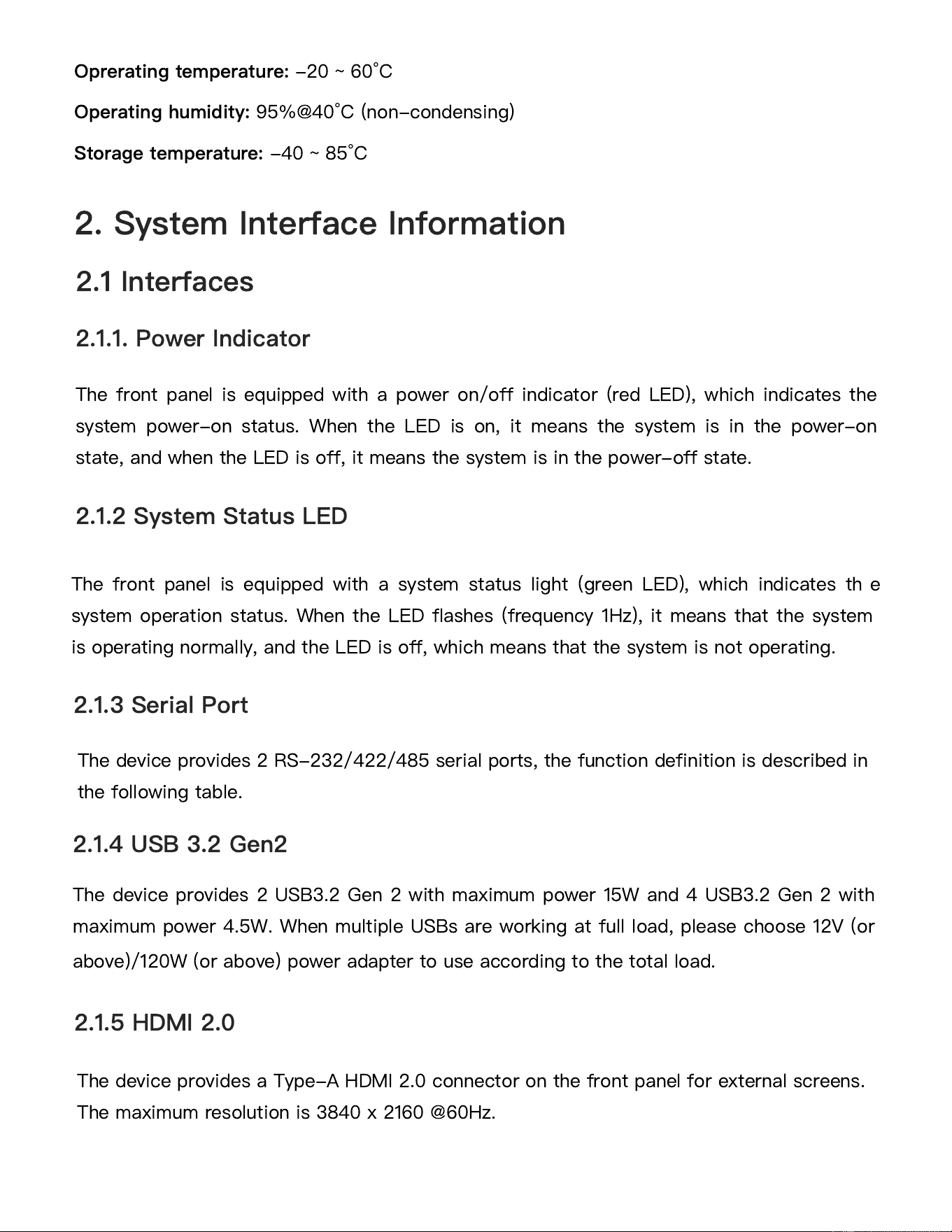
Standard Size:
180.0 x 160.0 x 60.0 mm
Reference Weight:
1.65 kg (excluding package and power adapter)
Power Type:
AT
Power Input:
DC 9-36 V
,
Max Power: 60W. The input power should be less than 100W.
1.2.3 Internal System Interfaces
1.3 Mechanical Specifications
1.4 Electrical Specifications
1.5 Environmental Specifications
Oprerating temperature:
-20 ~ 60°C
Operating humidity:
95%@40°C (non-condensing)
Storage temperature:
-40 ~ 85°C
2. System Interface Information
2.1 Interfaces
2.1.1. Power Indicator
The front panel is equipped with a power on/off indicator (red LED), which indicates the
system power-on status. When the LED is on, it means the system is in the power-on
state, and when the LED is off, it means the system is in the power-off state.
2.1.2 System Status LED
The front panel is equipped with a system status light (green LED), which indicates th
e
system operation status. When the LED flashes (frequency 1Hz), it means that the system
is operating normally, and the LED is off, which means that the system is not operating.
2.1.3 Serial Port
The device provides 2 RS-232/422/485 serial ports, the function definition is described in
the following table.
The
device provides 2 USB3.2 Gen 2 with maximum power 15W and 4 USB3.2 Gen 2 with
maximum power 4.5W. When multiple USBs are working at full load, please choose 12V (or
above)/120W (or above) power adapter to use according to the total load.
2.1.4 USB 3.2 Gen2
2.1.5 HDMI 2.0
The device provides a Type-A HDMI 2.0 connector on the front panel for external screens.
The maximum resolution is 3840 x 2160 @60Hz.
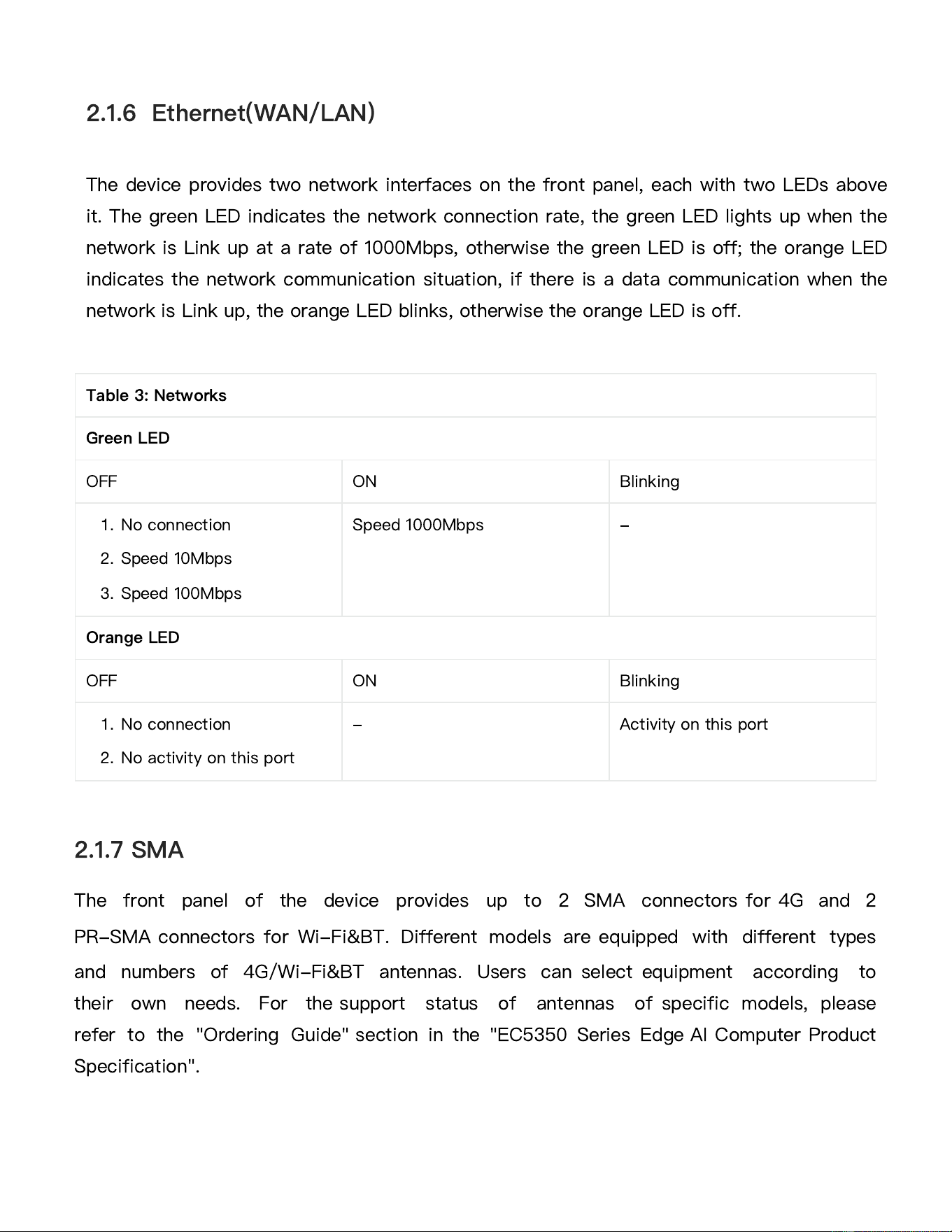
The front panel of the device provides up to 2 SMA connectors for 4G and 2
PR-SMA connectors for Wi-Fi&BT. Different models are equipped with different types
and numbers of 4G/Wi-Fi&BT antennas. Users can select equipment according to
their own needs. For the support status of antennas of specific models, please
refer to the "Ordering Guide" section in the "EC5350 Series Edge AI Computer Product
Specification".
2.1.7 SMA
Table 3: Networks
Green LED
OFF
ON Blinking
1.
No connection
2.
Speed 10Mbps
3.
Speed 100Mbps
Speed 1000Mbps
-
Orange LED
OFF
ON Blinking
1.
No connection
2.
No activity on this port
-
Activity on this port
The device provides two network interfaces on the front panel, each with two LEDs above
it. The green LED indicates the network connection rate, the green LED lights up when the
network is Link up at a rate of 1000Mbps, otherwise the green LED is off; the orange LED
indicates the network communication situation, if there is a data communication when the
network is Link up, the orange LED blinks, otherwise the orange LED is off.
2.1.6 Ethernet(WAN/LAN)
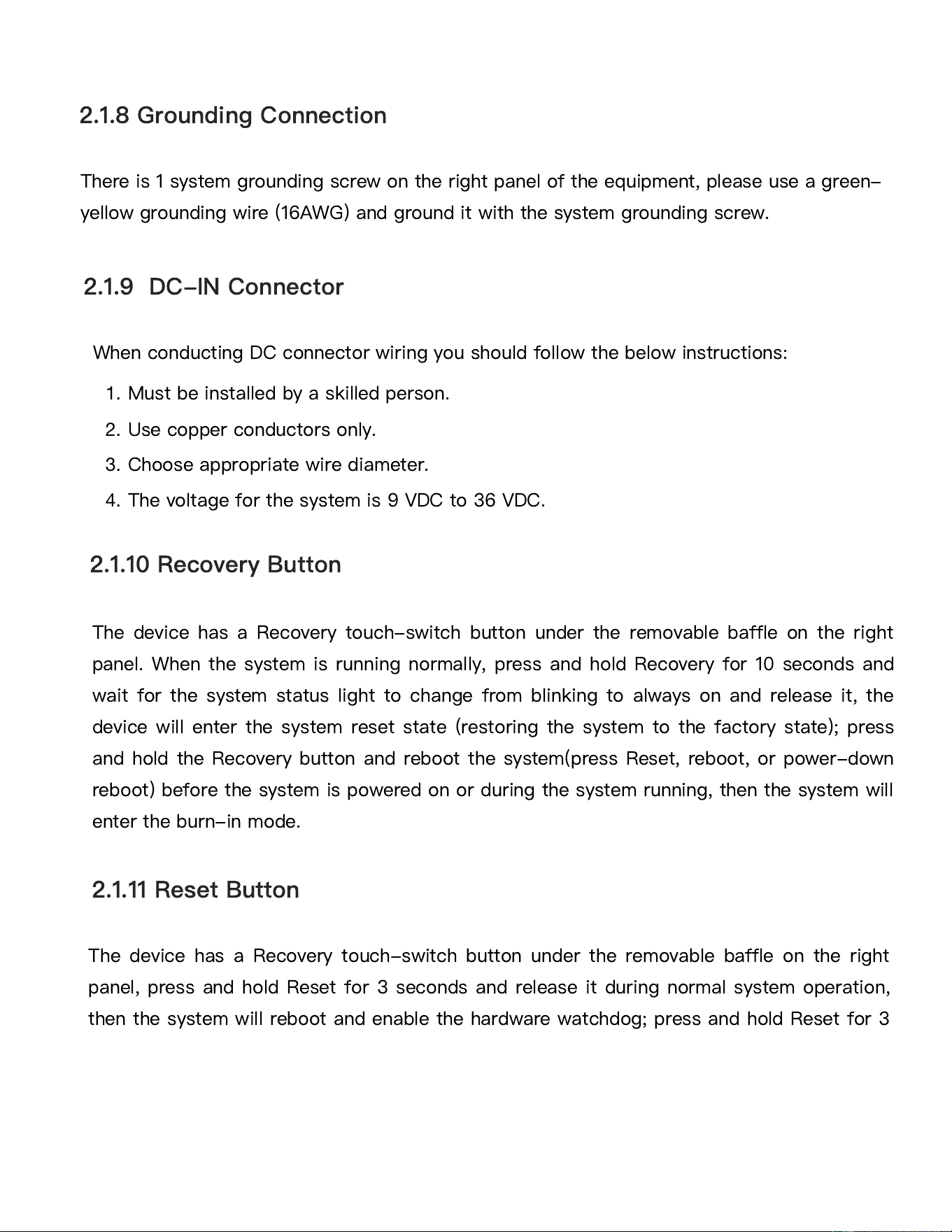
There is 1 system grounding screw on the right panel of the equipment, please use a green-
yellow grounding wire (16AWG) and ground it with the system grounding screw.
When conducting DC connector wiring you should follow the below instructions:
1.
Must be installed by a skilled person.
2.
Use copper conductors only.
3.
Choose appropriate wire diameter.
4.
The voltage for the system is 9 VDC to 36 VDC.
2.1.8 Grounding Connection
2.1.9 DC-IN Connector
2.1.10 Recovery Button
The device has a Recovery touch-switch button under the removable baffle on the right
panel. When the system is running normally, press and hold Recovery for 10 seconds and
wait for the system status light to change from blinking to always on and release it, the
device will enter the system reset state (restoring the system to the factory state); press
and hold the Recovery button and reboot the system(press Reset, reboot, or power-down
reboot) before the system is powered on or during the system running, then the system will
enter the burn-in mode.
2.1.11 Reset Button
The device has a Recovery touch-switch button under the removable baffle on the right
panel, press and hold Reset for 3 seconds and release it during normal system operation,
then the system will reboot and enable the hardware watchdog; press and hold Reset for 3
seconds and then release it during normal system operation, then the system will reboot
and disable the hardware watchdog, please disable the hardware watchdog before the
system is burned in, to prevent the hardware watchdog from restarting the system and
leading to the failure of the burn-in process.
The equipment has a USB 2.0 Type-C connector under the emovable baffle on the right
panel for connecting to a host burning system in burn-in mode.
The device has a TF card slot under the removable baffle on the right panel, which
supports
Micro SD memory cards. When there is a need for additional storage space,
please insert a Micro SD card with a capacity of at least 8GB into this card slot for
subsequent use.
2.1.12 USB 2.0 Type-C
2.1.13 TF Card
2.1.14 SIM Card Slot
The device has 2 SIM card slots (SIM1/SIM2) on the right panel to support standard SIM
cards, please insert at least 1 available SIM when using the cellular function.
2.1.15 CAN FD
The device has 1 CAN FD interface (on-board 120
Ω
resistor) on the right panel, supporting
a maximum communication rate of 5Mbps.
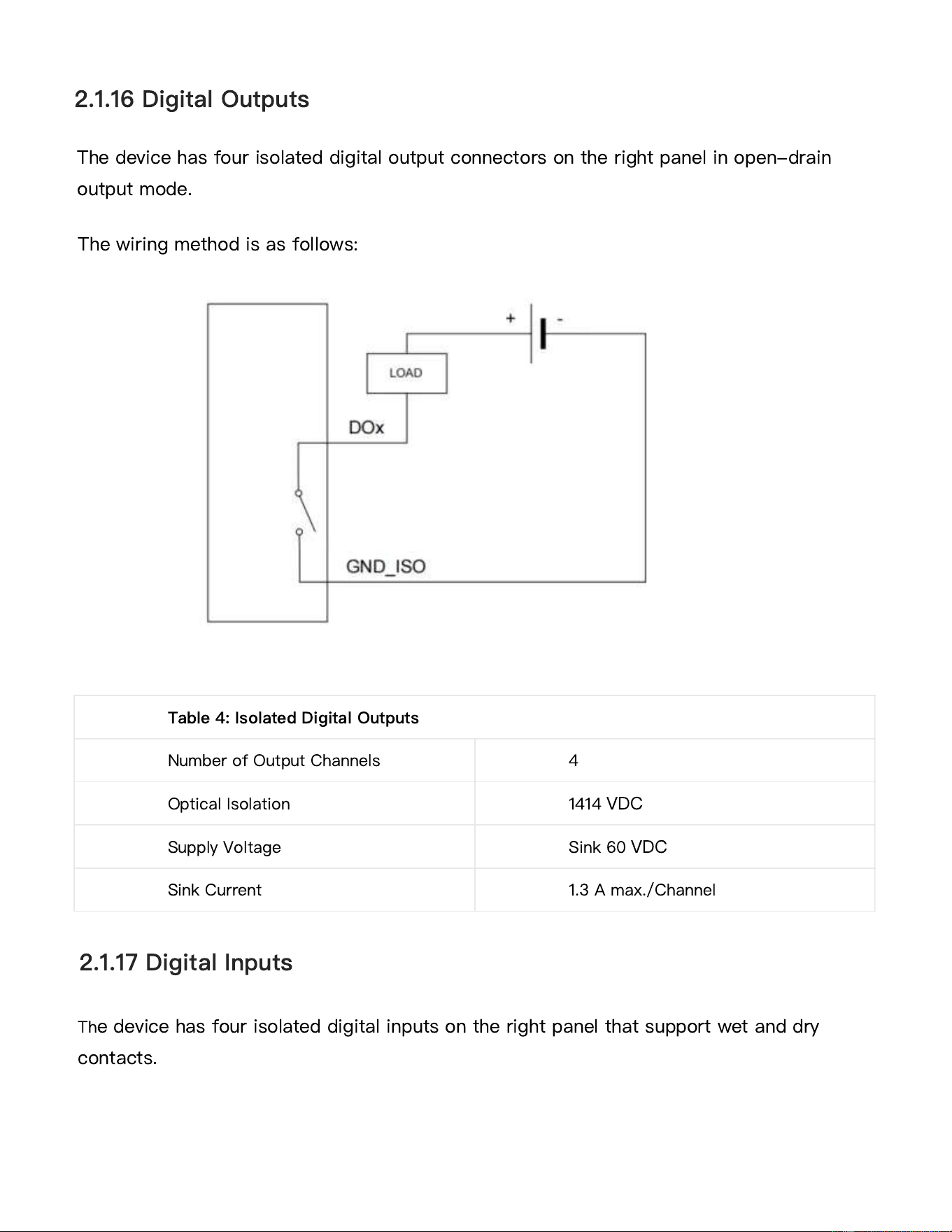
The device has four isolated digital output connectors on the right panel in open-drain
output mode.
The wiring method is as follows:
2.1.16 Digital Outputs
Table 4: Isolated Digital Outputs
Number of Output Channels
4
Optical Isolation
1414
VDC
Supply Voltage
Sink 60
VDC
Sink Current 1.3 A max./Channel
2.1.17 Digital Inputs
Th
e device has four isolated digital inputs on the right panel that support wet and dry
contacts.
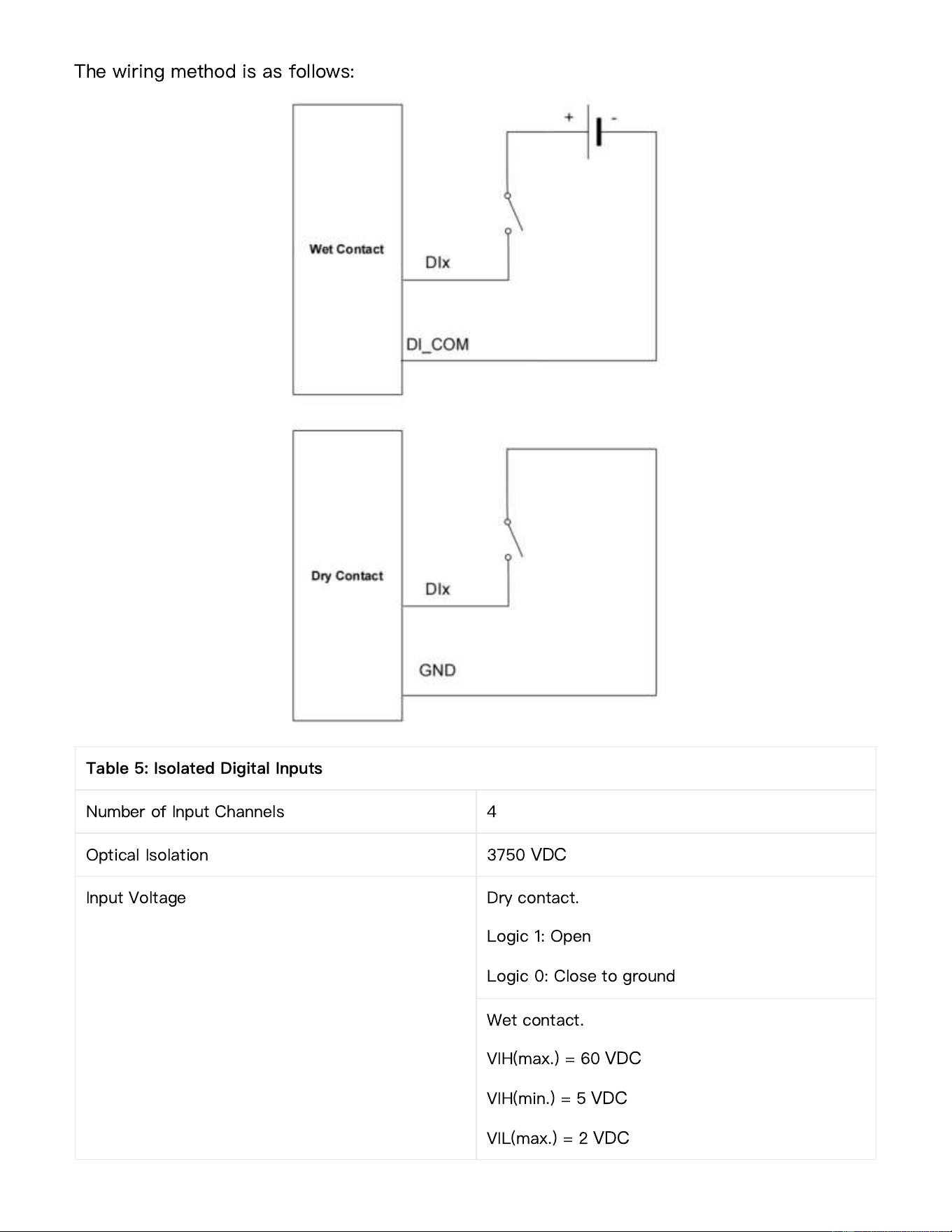
The wiring method is as follows:
Table 5: Isolated Digital Inputs
Number of Input Channels
4
Optical Isolation
3750
VDC
Input Voltage
Dry contact.
Logic 1: Open
Logic 0: Close to ground
Wet contact.
VIH(max.) = 60
VDC
VIH(min.) = 5
VDC
VIL(max.) = 2
VDC
The device has 1 RS-485 pull-up and pull-down dip switches on the right panel to control
the pull-up and pull-down resistors of the RS-485 bus (corresponding to COM1/COM2).
The device has 2 GMSL 2.0 ports on the right panel, supporting docking of 2 GMSL
cameras.
2.2.18 RS-485 Pull-up/down Dip Switches
2.2.19 GMSL 2.0
Table 6: RS-485 Pull-up/down
PU ON: Enable pull-up
OFF: Disable pull-up
PD ON: Enable pull-down
OFF: Disable pull-down
T
ON: Enable termination matching resistor
OFF: Disable termination matching resistor
2.2.20 Lineout
The device has 1 Line-out connector on the right panel, which supports 3.5mm standard
audio output.
2.2.21 Microphone
The device has 1 microphone connector on the right panel and supports 3.5mm standard
audio input.
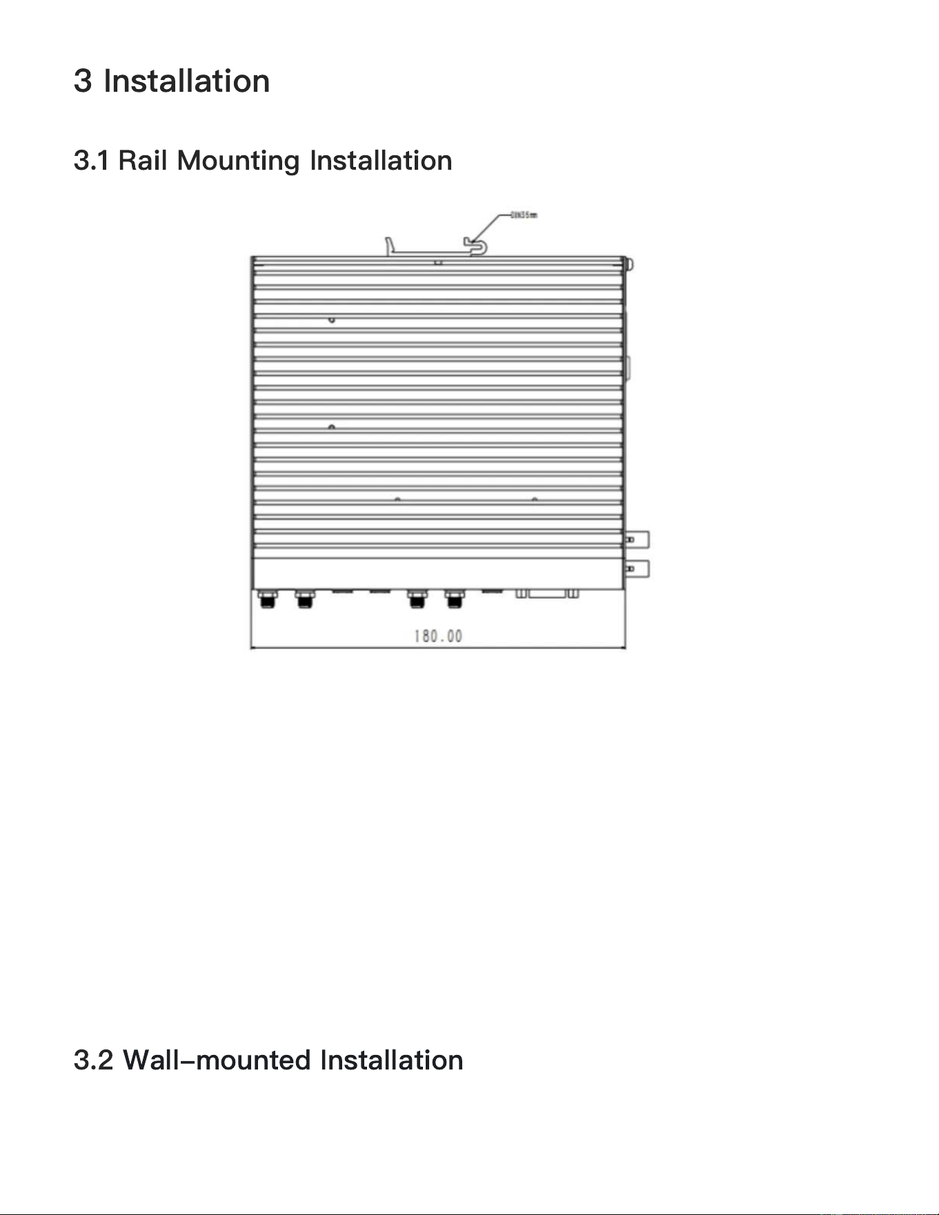
3 Installation
3.1 Rail Mounting Installation
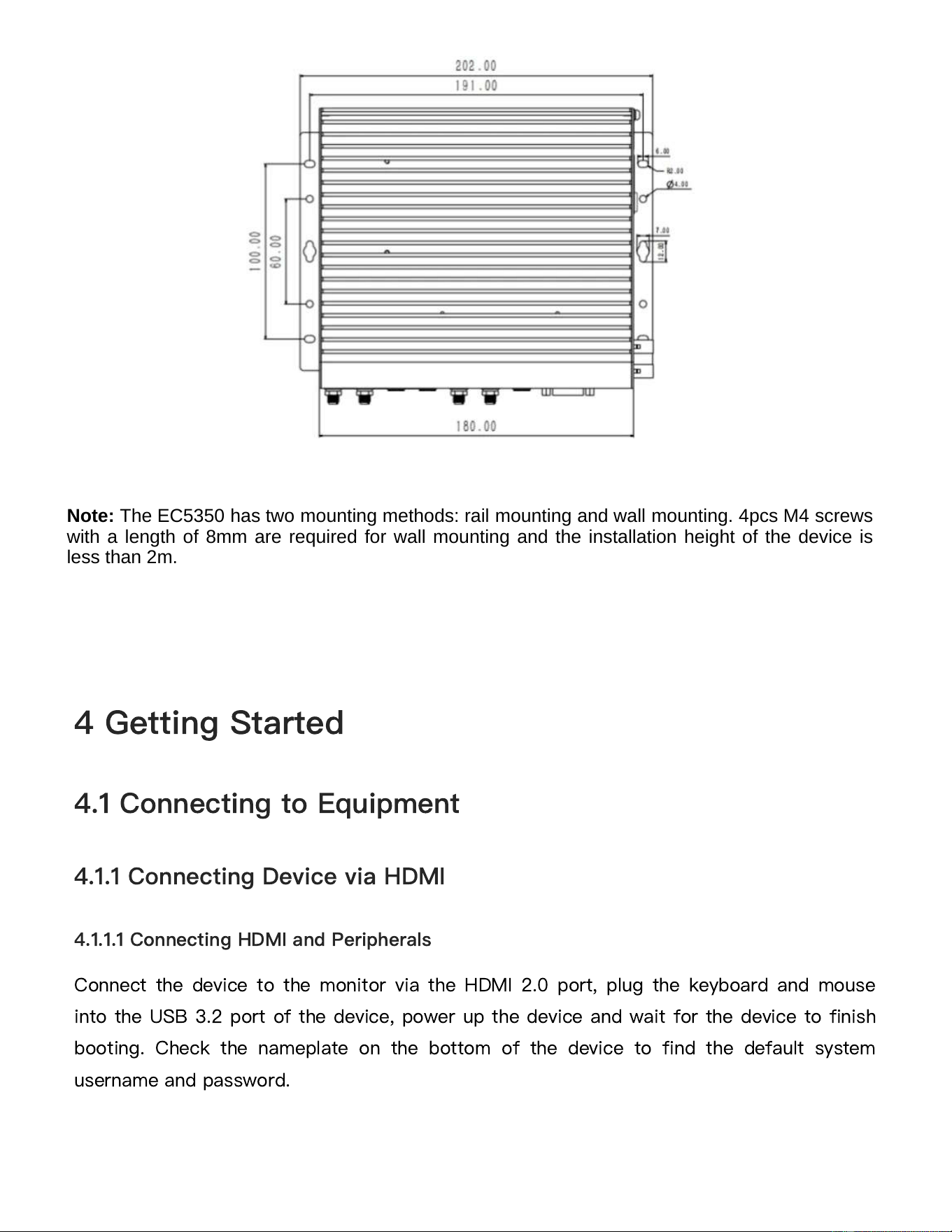
3.2 Wall-mounted Installation
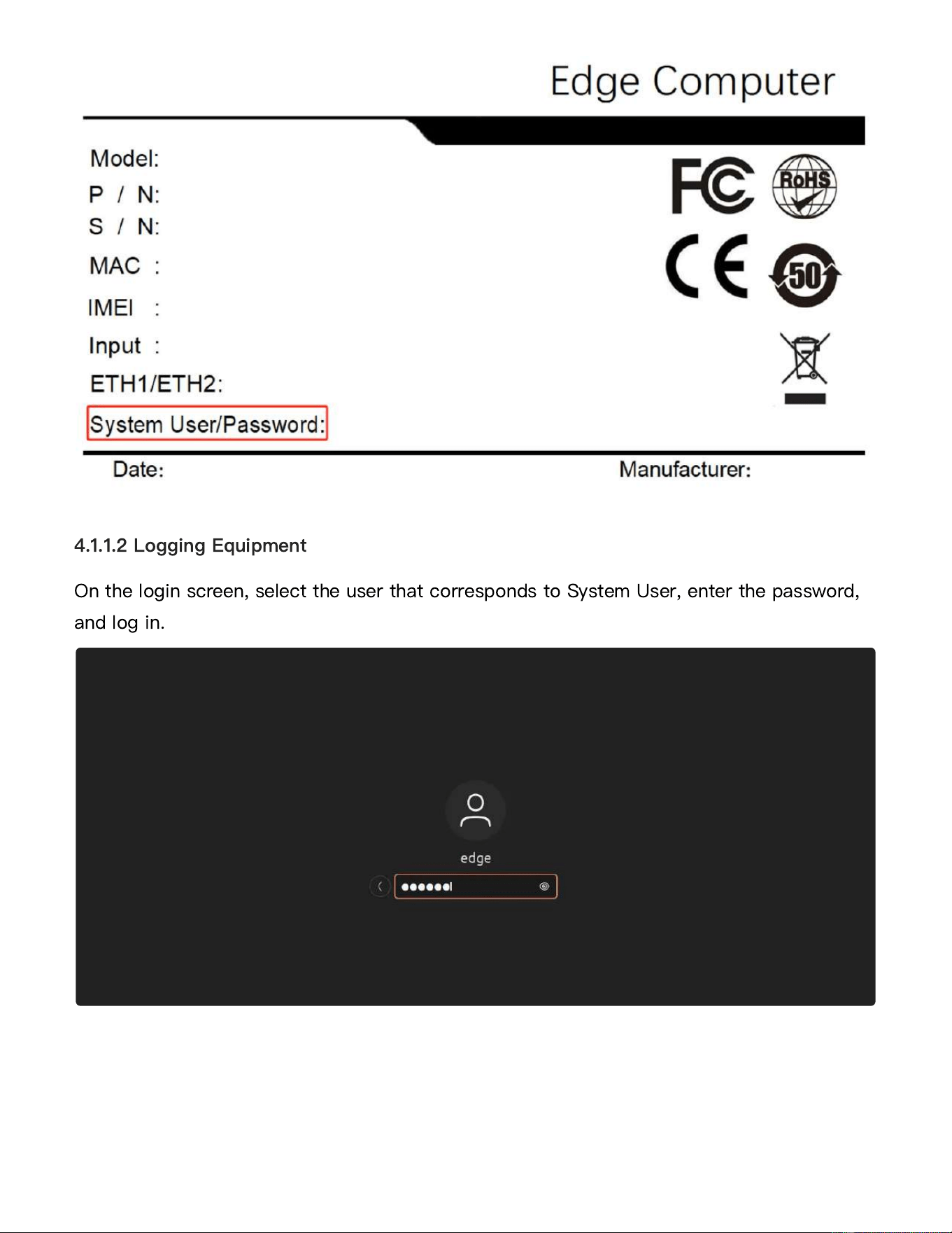
Connect the device to the monitor via the HDMI 2.0 port, plug the keyboard and mouse
into the USB 3.2 port of the device, power up the device and wait for the device to finish
booting. Check the nameplate on the bottom of the device to find the default system
username and password.
4 Getting Started
4.1 Connecting to Equipment
4.1.1 Connecting Device via HDMI
4.1.1.1 Connecting HDMI and Peripherals
Note: The EC5350
has two mounting methods: rail mounting and wall mounting. 4pcs M4 screws
with a length of 8mm are required for wall mounting and the installation height of the device is
less than 2m.
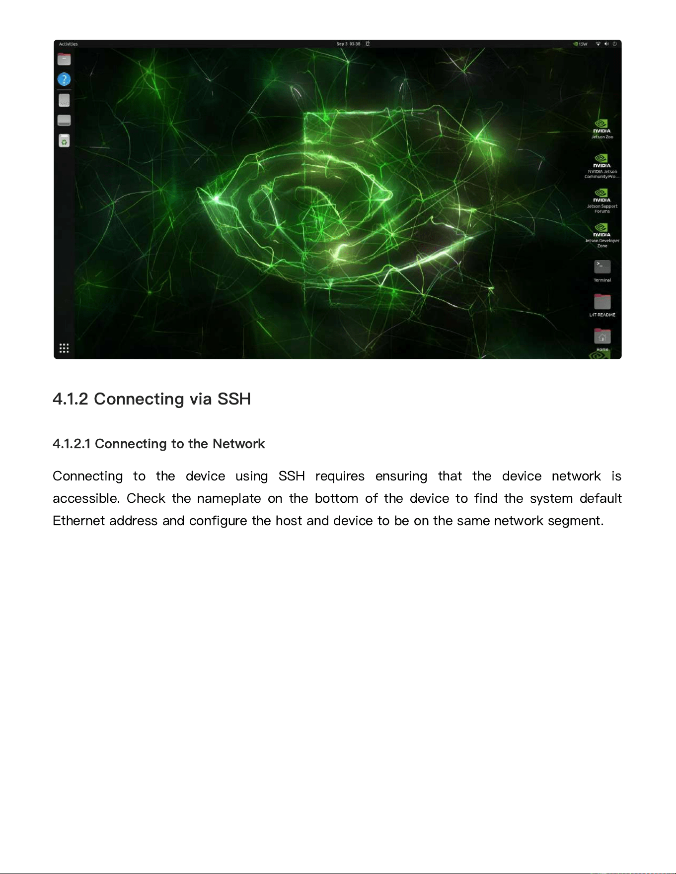
On the login screen, select the user that corresponds to System User, enter the password,
and log in.
4.1.1.2 Logging Equipment
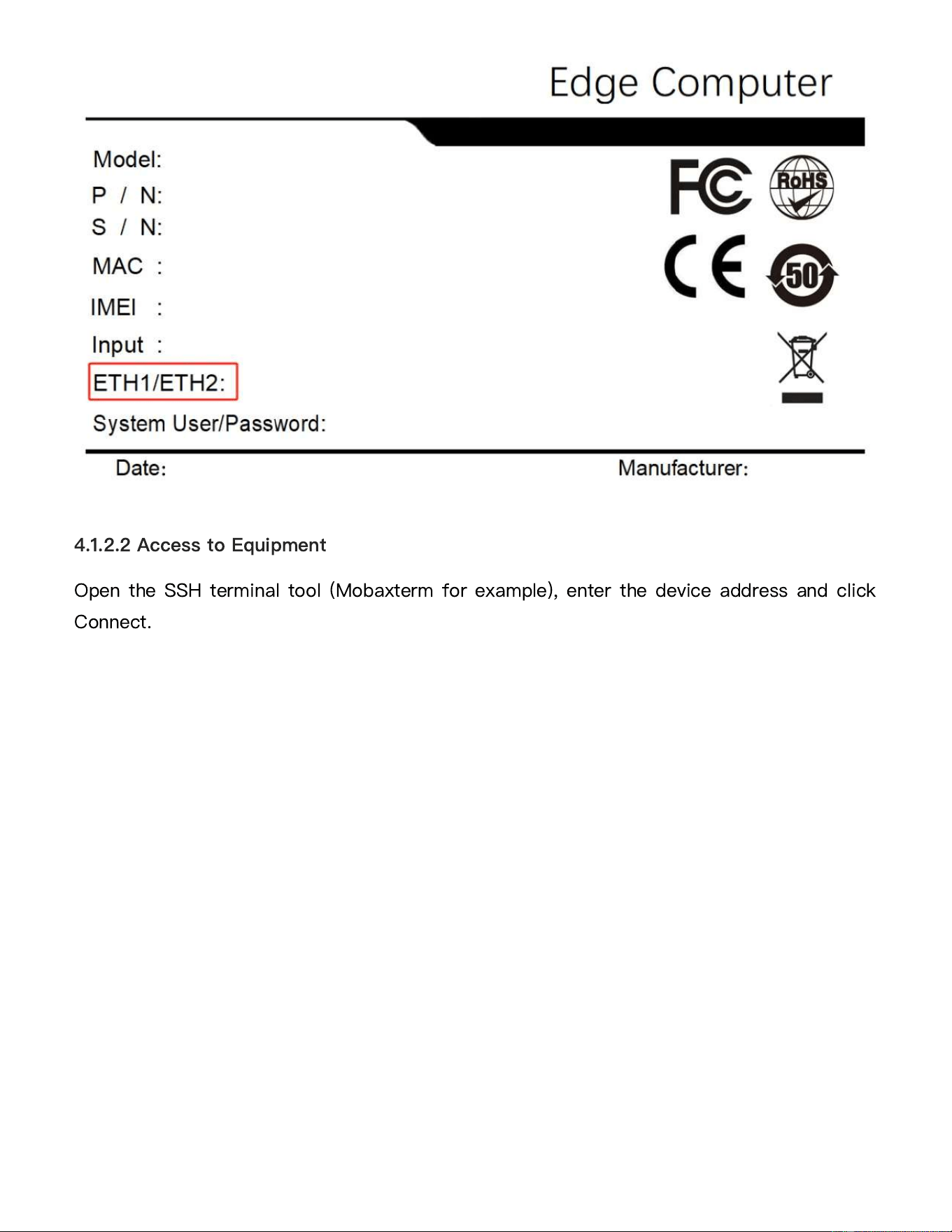
Connecting to the device using SSH requires ensuring that the device network is
accessible. Check the nameplate on the bottom of the device to find the system default
Ethernet address and configure the host and device to be on the same network segment.
4.1.2 Connecting via SSH
4.1.2.1 Connecting to the Network
Open the SSH terminal tool (Mobaxterm for example), enter the device address and click
Connect.
4.1.2.2 Access to Equipment
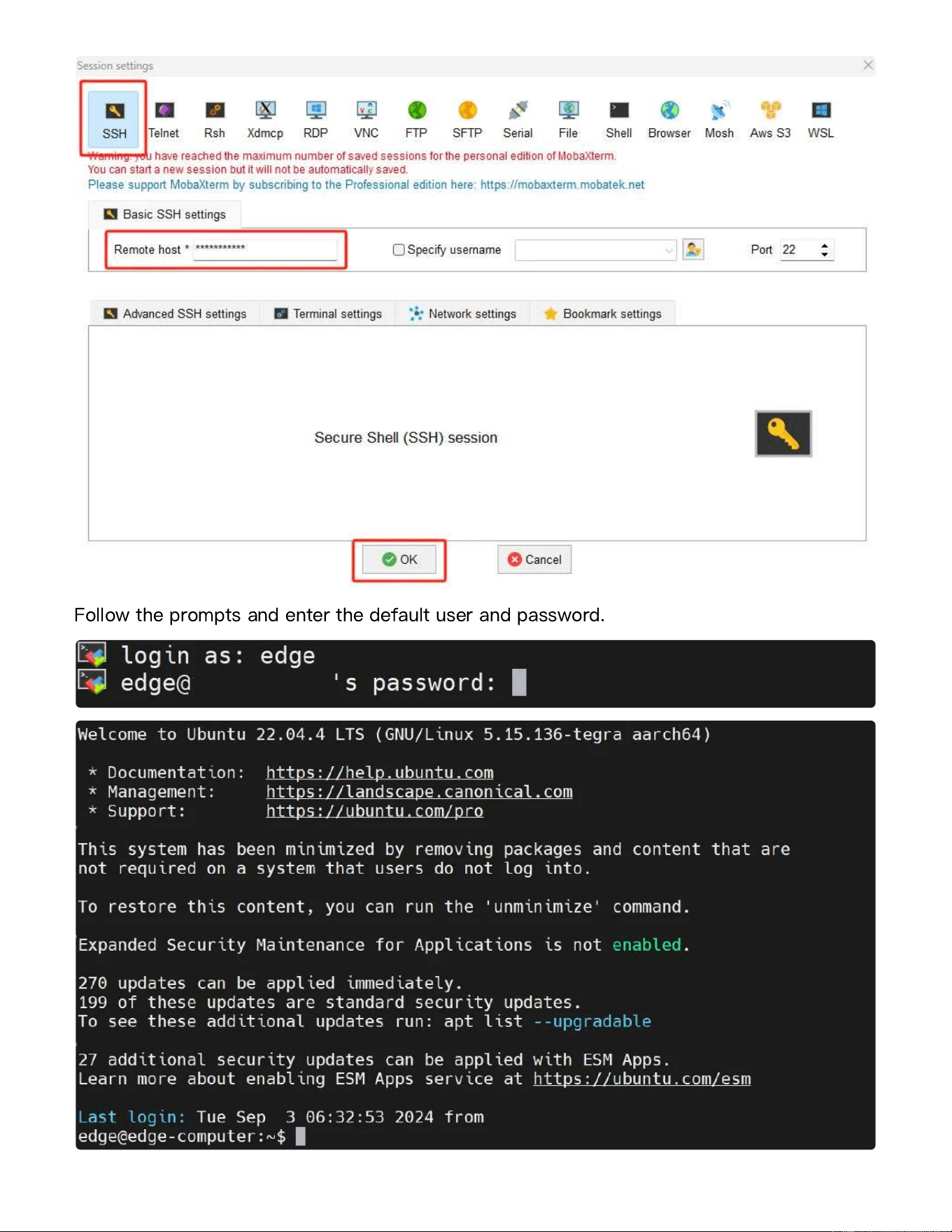
Follow the prompts and enter the default user and password.
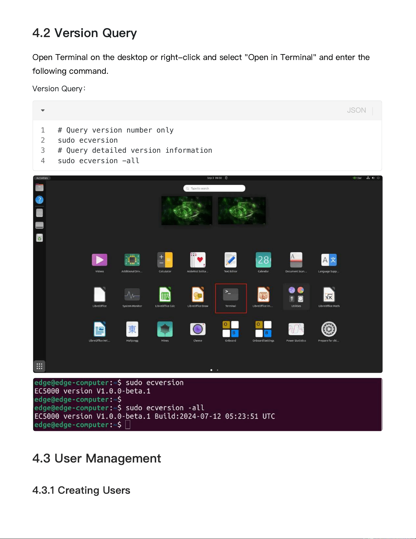
Open Terminal on the desktop or right-click and select "Open in Terminal" and enter the
following command.
Version Query
:
4.2 Version Query
4.3 User Management
4.3.1 Creating Users
# Query version number only
sudo ecversion
# Query detailed version information
sudo ecversion -all
1
2
3
4
JSON
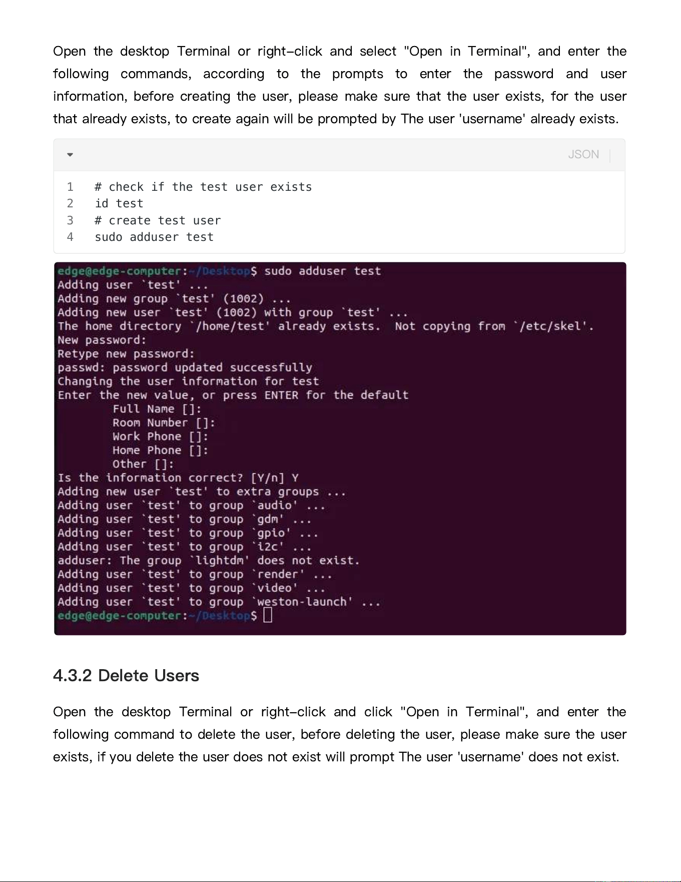
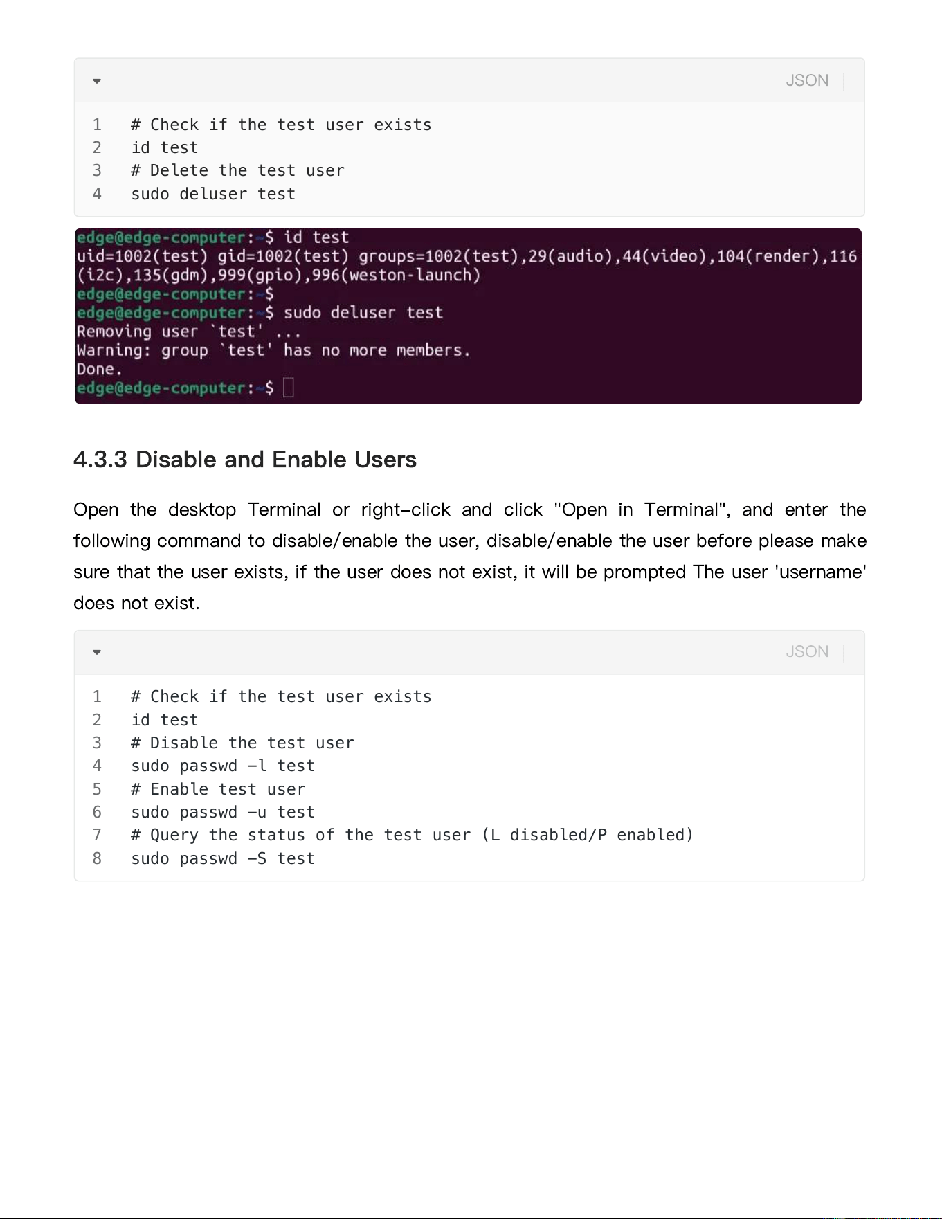
Open the desktop Terminal or right-click and select "Open in Terminal", and enter the
following commands, according to the prompts to enter the password and user
information, before creating the user, please make sure that the user exists, for the user
that already exists, to create again will be prompted by The user 'username' already exists.
Open the desktop Terminal or right-click and click "Open in Terminal", and enter the
following command to delete the user, before deleting the user, please make sure the user
exists, if you delete the user does not exist will prompt The user 'username' does not exist.
4.3.2 Delete Users
# check if the test user exists
id test
# create test user
sudo adduser test
1
2
3
4
JSON
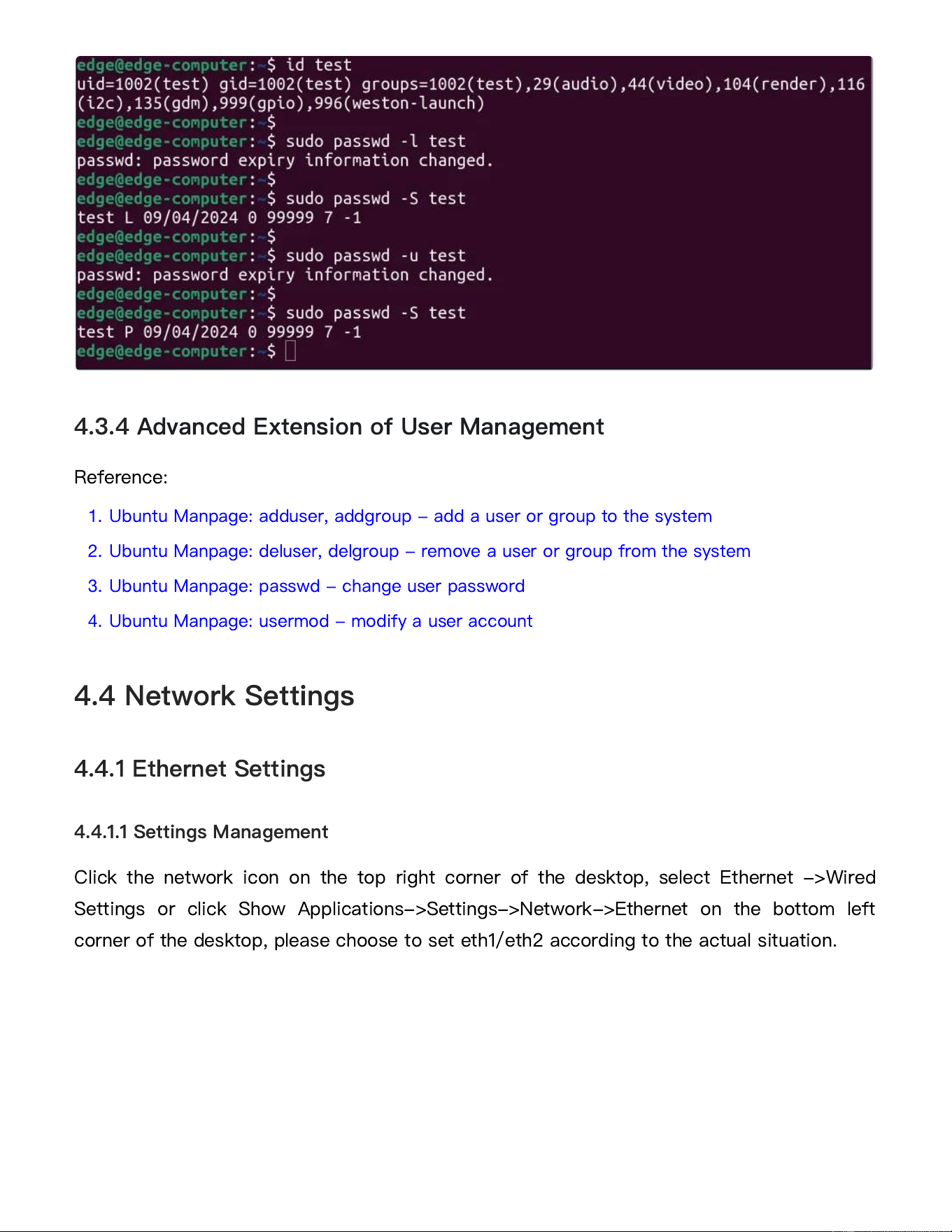
Open the desktop Terminal or right-click and click "Open in Terminal", and enter the
following command to disable/enable the user, disable/enable the user before please make
sure that the user exists, if the user does not exist, it will be prompted The user 'username'
does not exist.
4.3.3 Disable and Enable Users
# Check if the test user exists
id test
# Delete the test user
sudo deluser test
1
2
3
4
JSON
# Check if the test user exists
id test
# Disable the test user
sudo passwd -l test
# Enable test user
sudo passwd -u test
# Query the status of the test user (L disabled/P enabled)
sudo passwd -S test
1
2
3
4
5
6
7
8
JSON
Reference:
1.
Ubuntu Manpage: adduser, addgroup - add a user or group to the system
2.
Ubuntu Manpage: deluser, delgroup - remove a user or group from the system
3.
Ubuntu Manpage: passwd - change user password
4.
Ubuntu Manpage: usermod - modify a user account
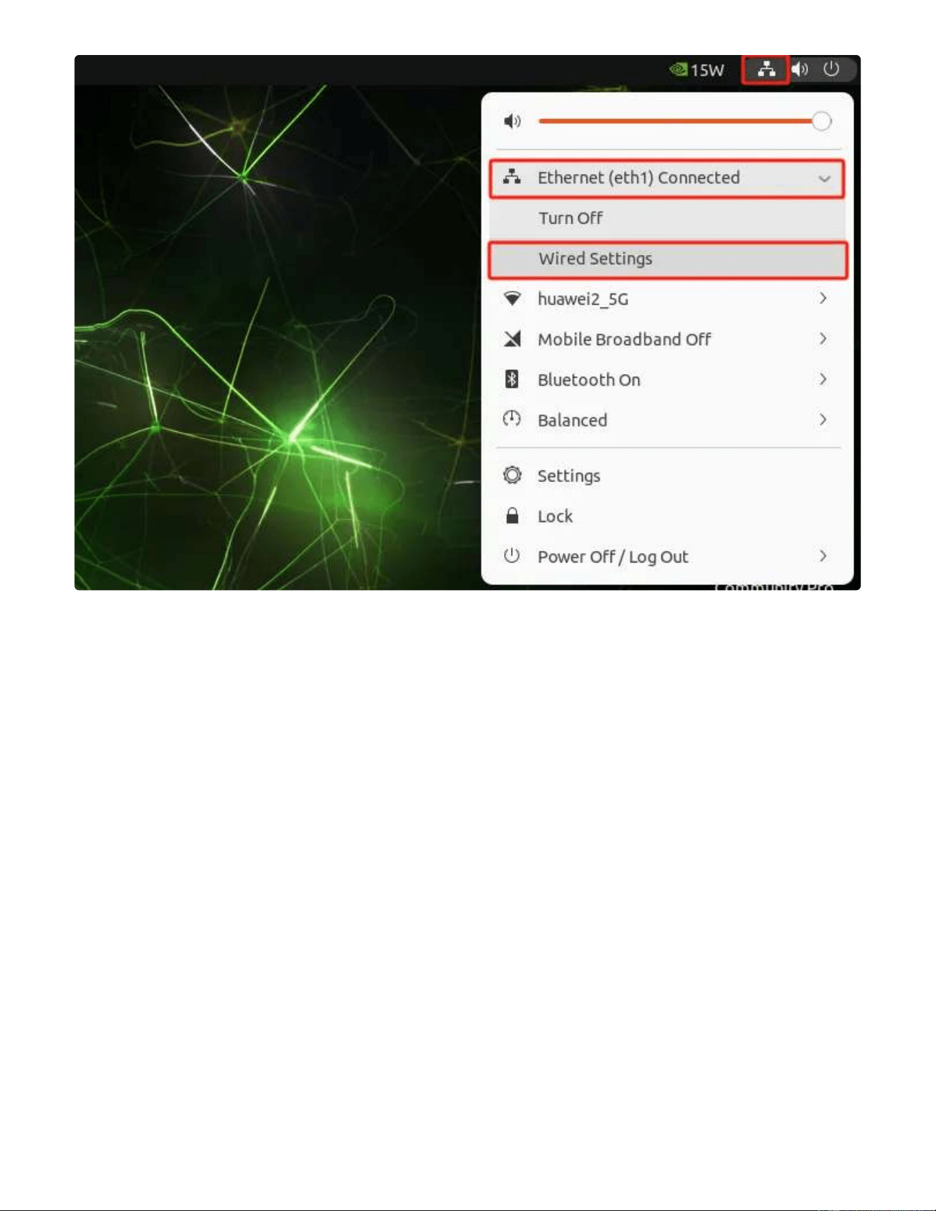
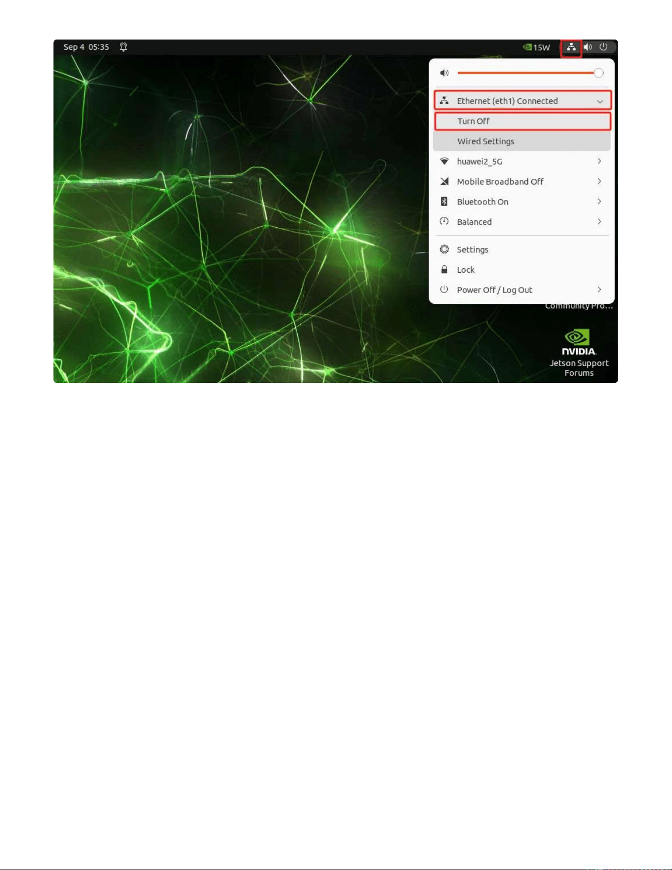
Click the network icon on the top right corner of the desktop, select Ethernet ->Wired
Settings or click Show Applications->Settings->Network->Ethernet on the bottom left
corner of the desktop, please choose to set eth1/eth2 according to the actual situation.
4.3.4 Advanced Extension of User Management
4.4 Network Settings
4.4.1 Ethernet Settings
4.4.1.1 Settings Management
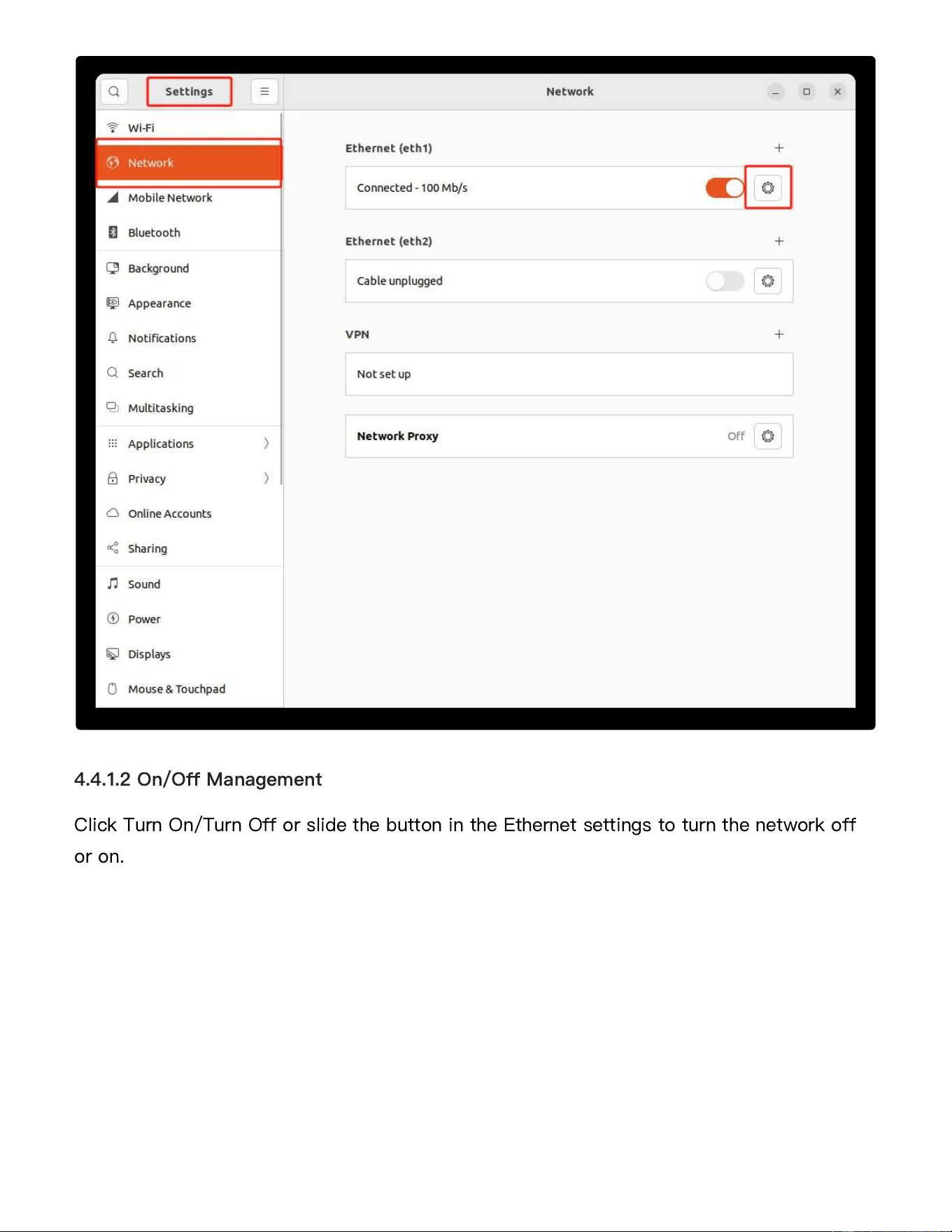
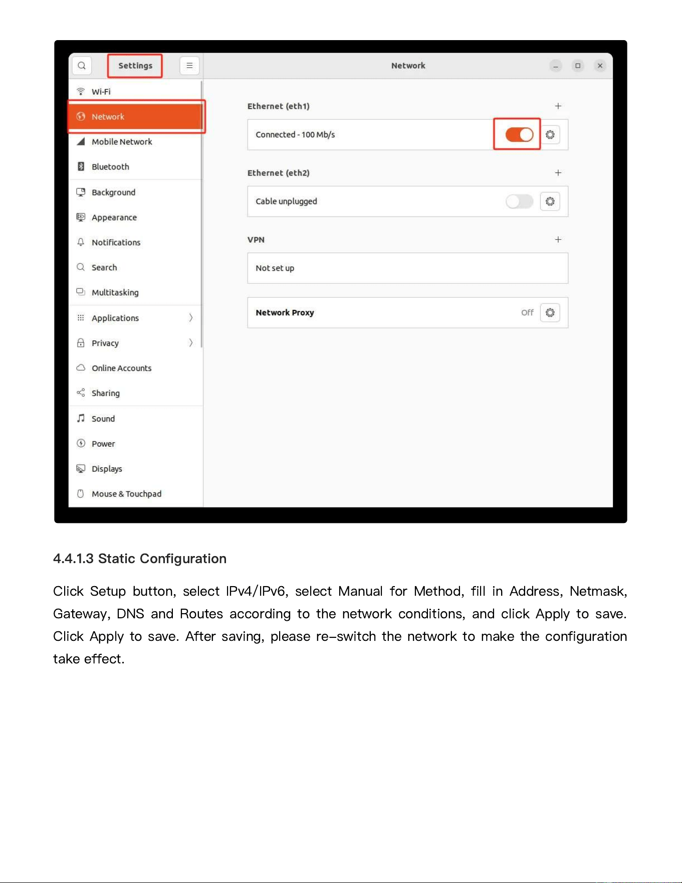
Click Turn On/Turn Off or slide the button in the Ethernet settings to turn the network off
or on.
4.4.1.2 On/Off Management
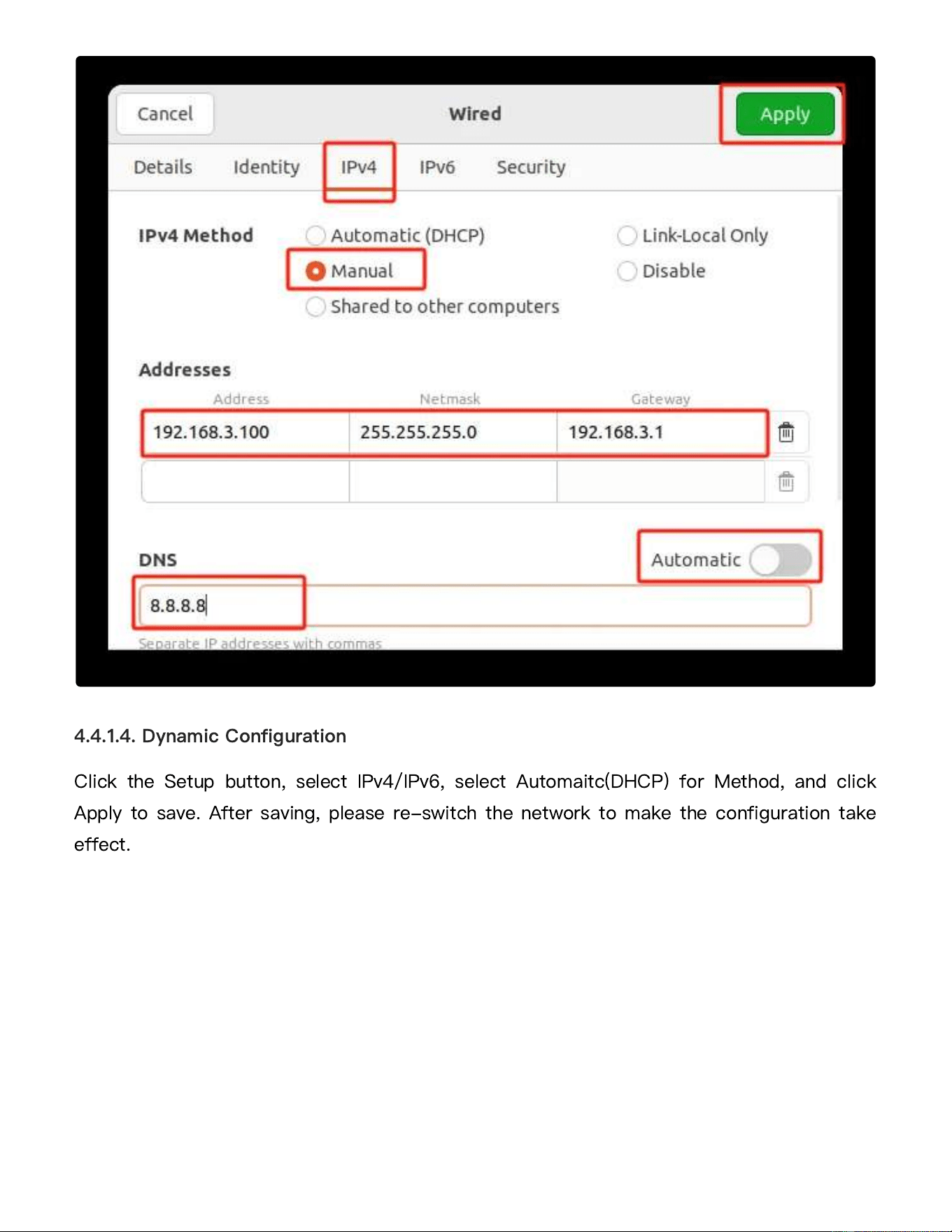
Click Setup button, select IPv4/IPv6, select Manual for Method, fill in Address, Netmask,
Gateway, DNS and Routes according to the network conditions, and click Apply to save.
Click Apply to save. After saving, please re-switch the network to make the configuration
take effect.
4.4.1.3 Static Configuration
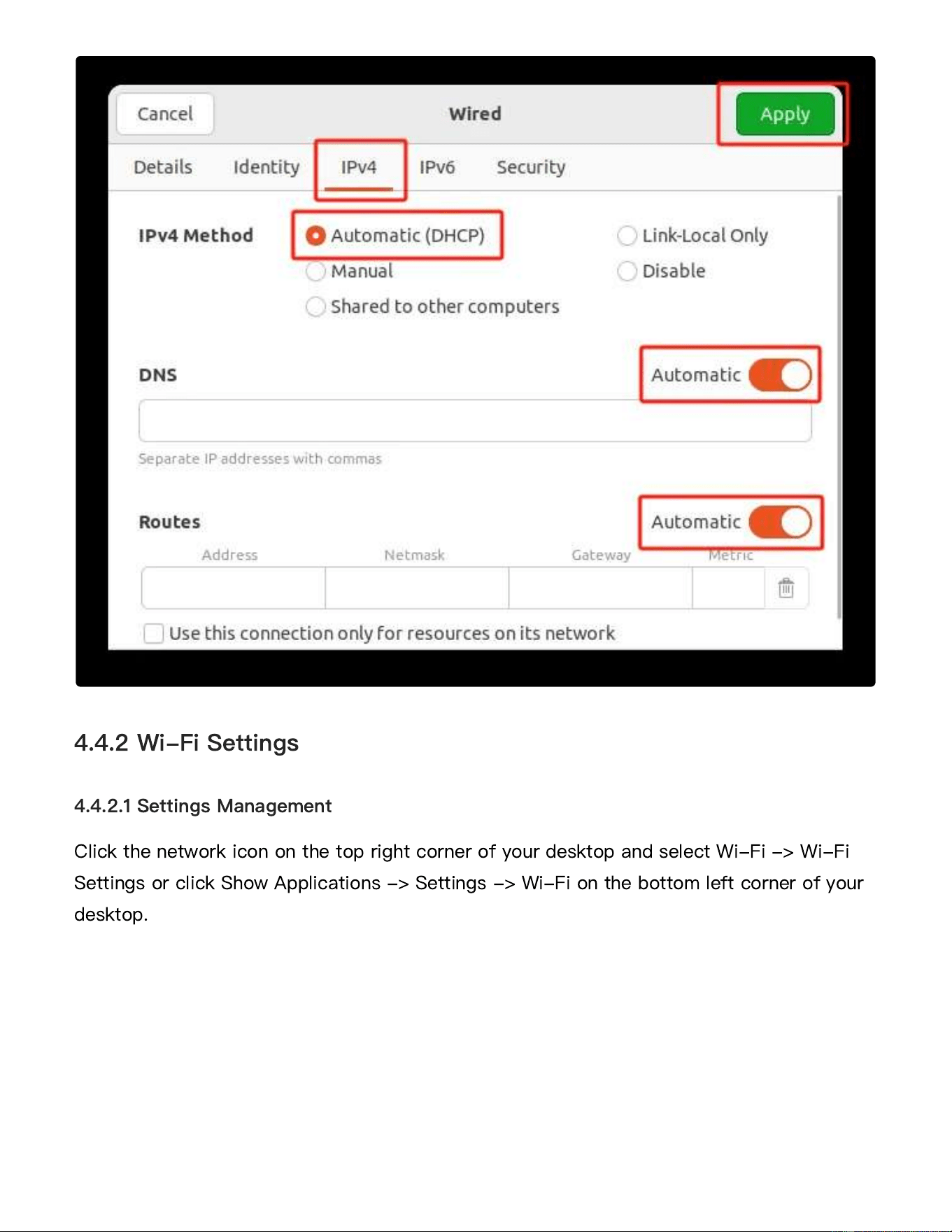
Click the Setup button, select IPv4/IPv6, select Automaitc(DHCP) for Method, and click
Apply to save. After saving, please re-switch the network to make the configuration take
effect.
4.4.1.4. Dynamic Configuration
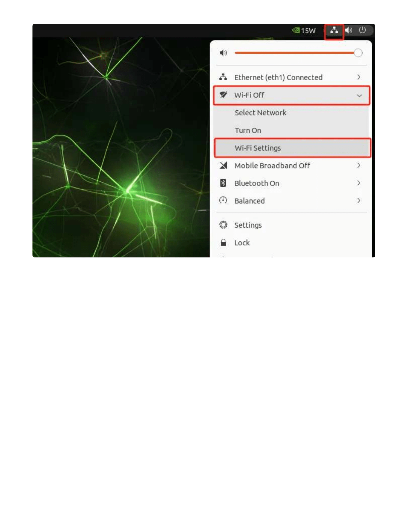
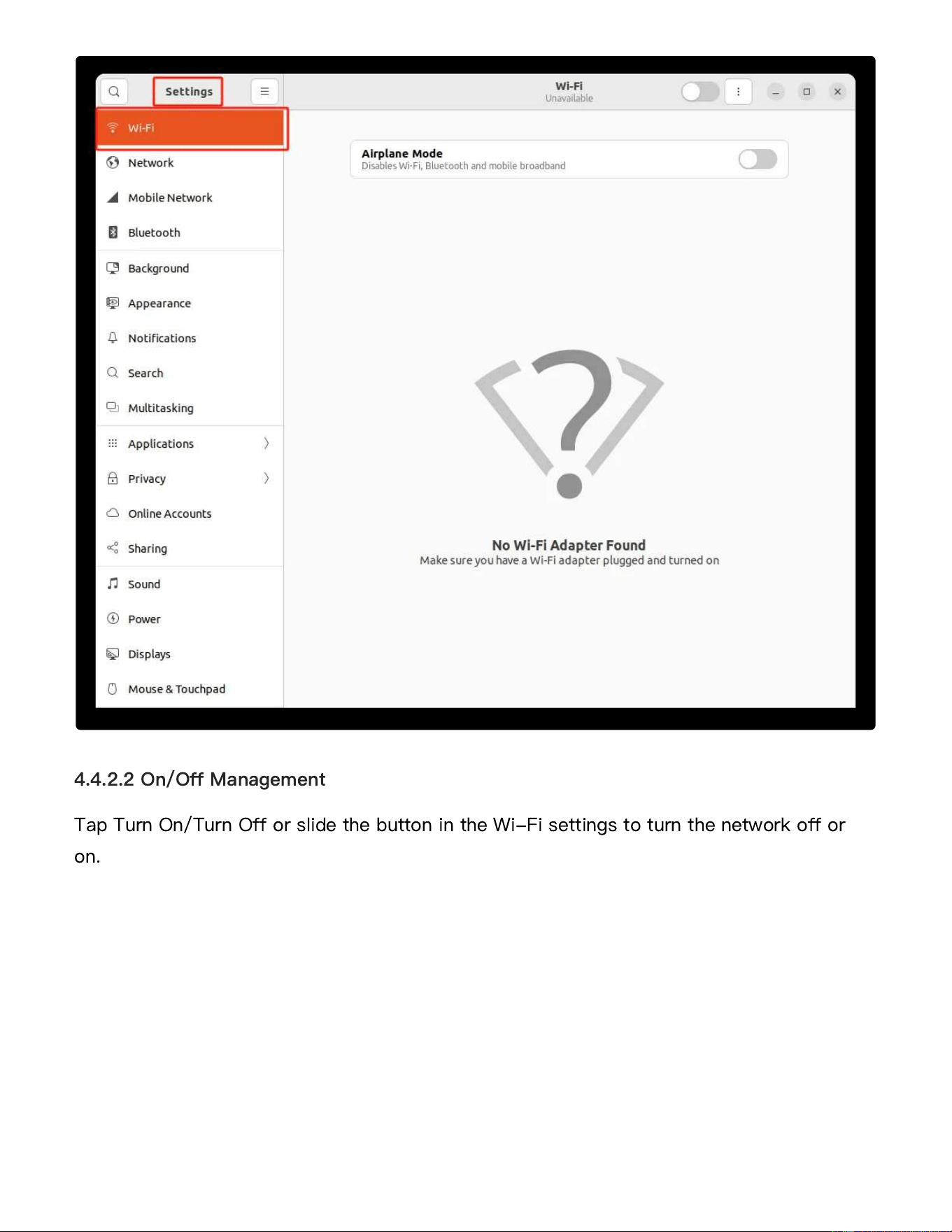
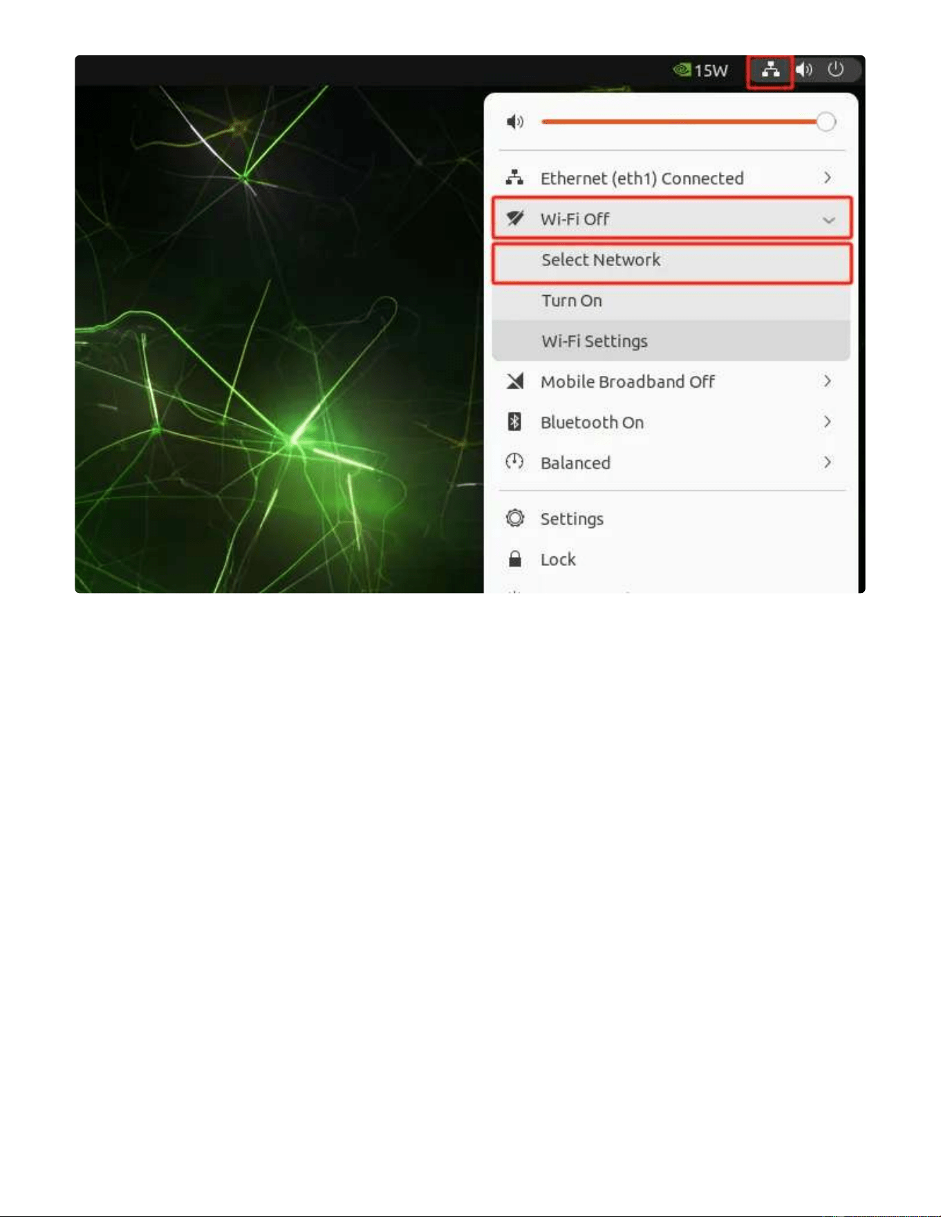
Click the network icon on the top right corner of your desktop and select Wi-Fi -> Wi-Fi
Settings or click Show Applications -> Settings -> Wi-Fi on the bottom left corner of your
desktop.
4.4.2 Wi-Fi Settings
4.4.2.1 Settings Management
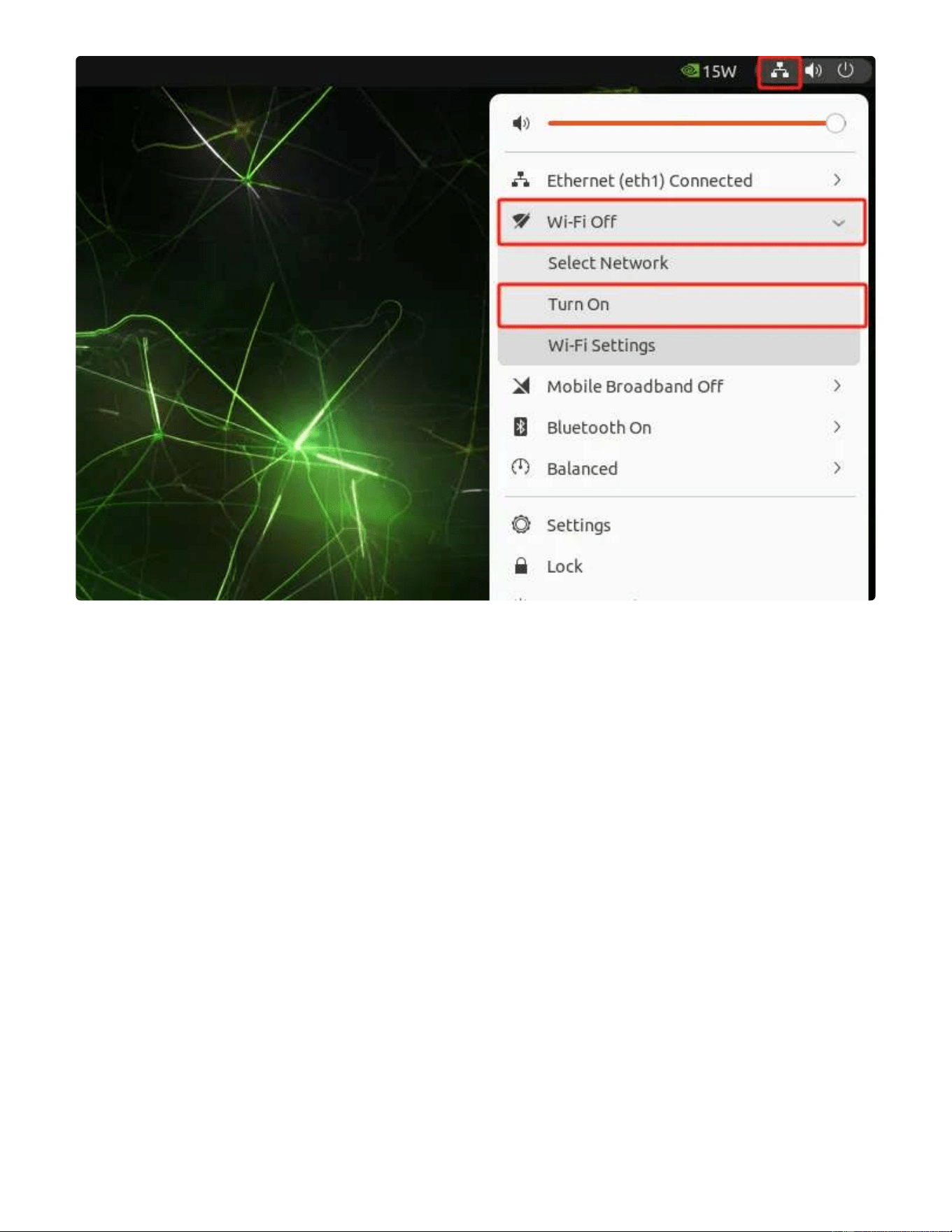
Tap Turn On/Turn Off or slide the button in the Wi-Fi settings to turn the network off or
on.
4.4.2.2 On/Off Management
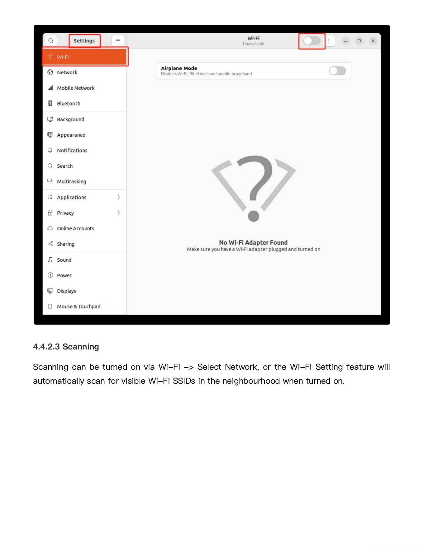
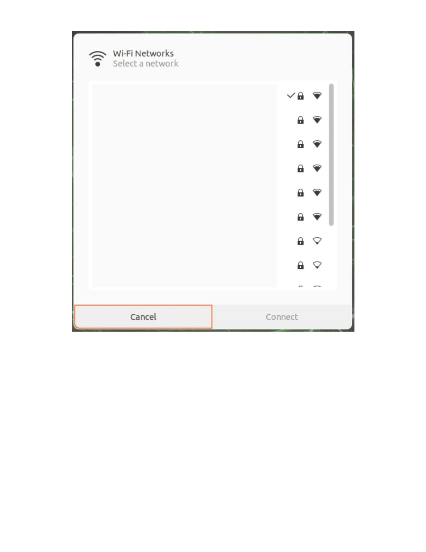
Scanning can be turned on via Wi-Fi -> Select Network, or the Wi-Fi Setting feature will
automatically scan for visible Wi-Fi SSIDs in the neighbourhood when turned on.
4.4.2.3 Scanning
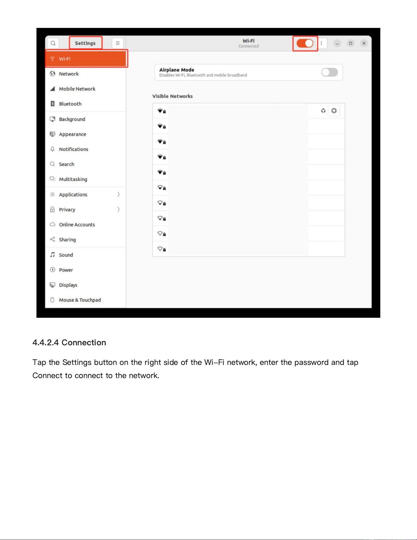
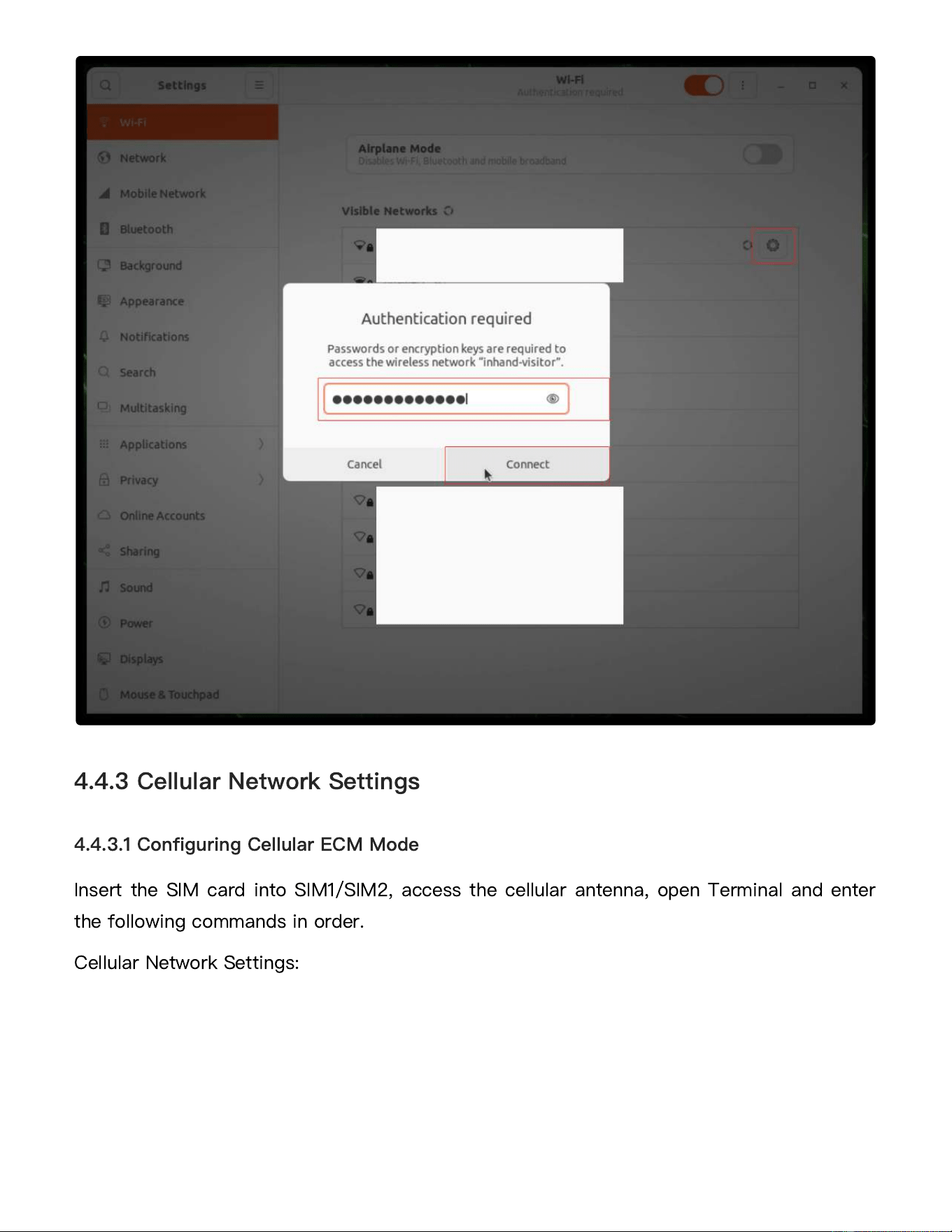
Tap the Settings button on the right side of the Wi-Fi network, enter the password and tap
Connect to connect to the network.
4.4.2.4 Connection
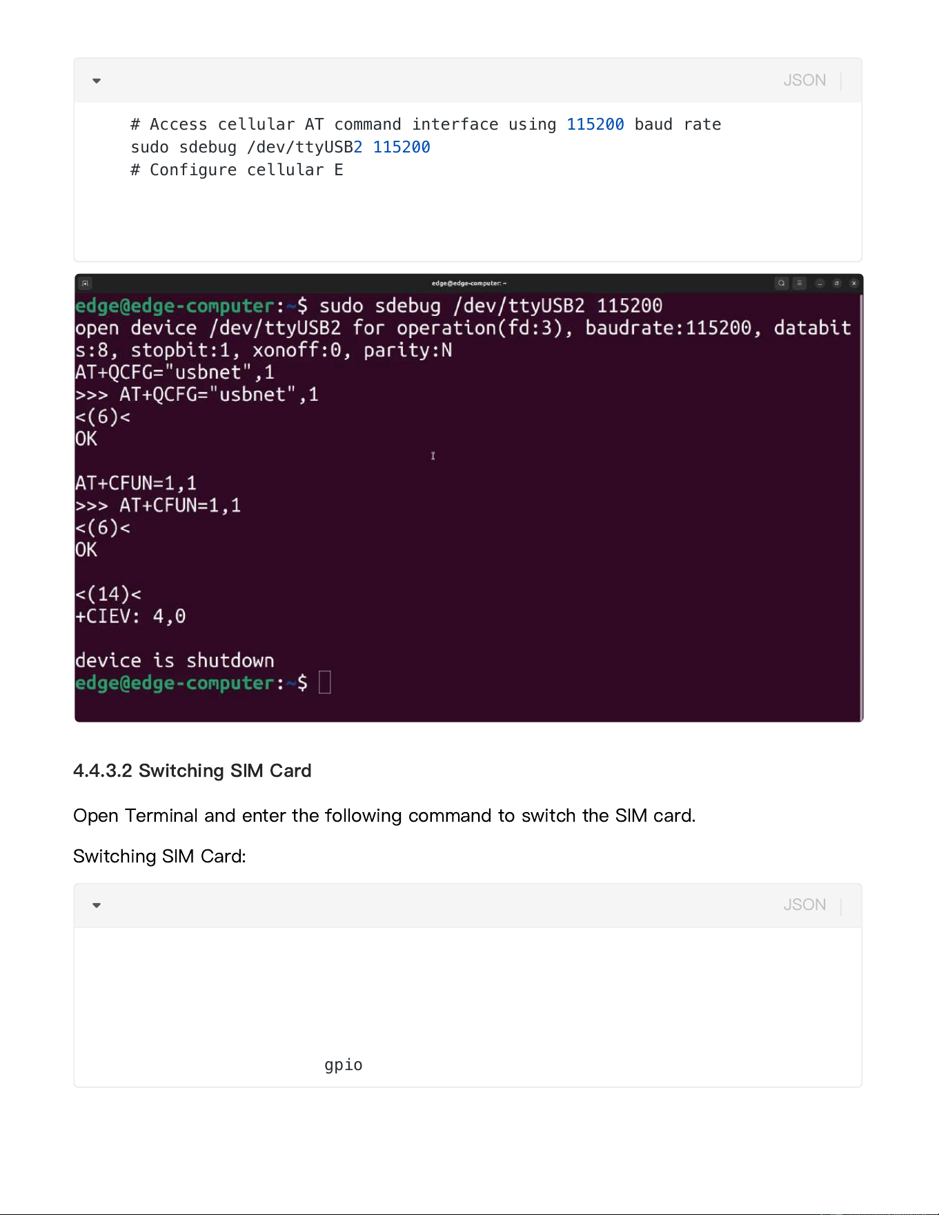
Insert the SIM card into SIM1/SIM2, access the cellular antenna, open Terminal and enter
the following commands in order.
Cellular Network Settings:
4.4.3 Cellular Network Settings
4.4.3.1 Configuring Cellular ECM Mode
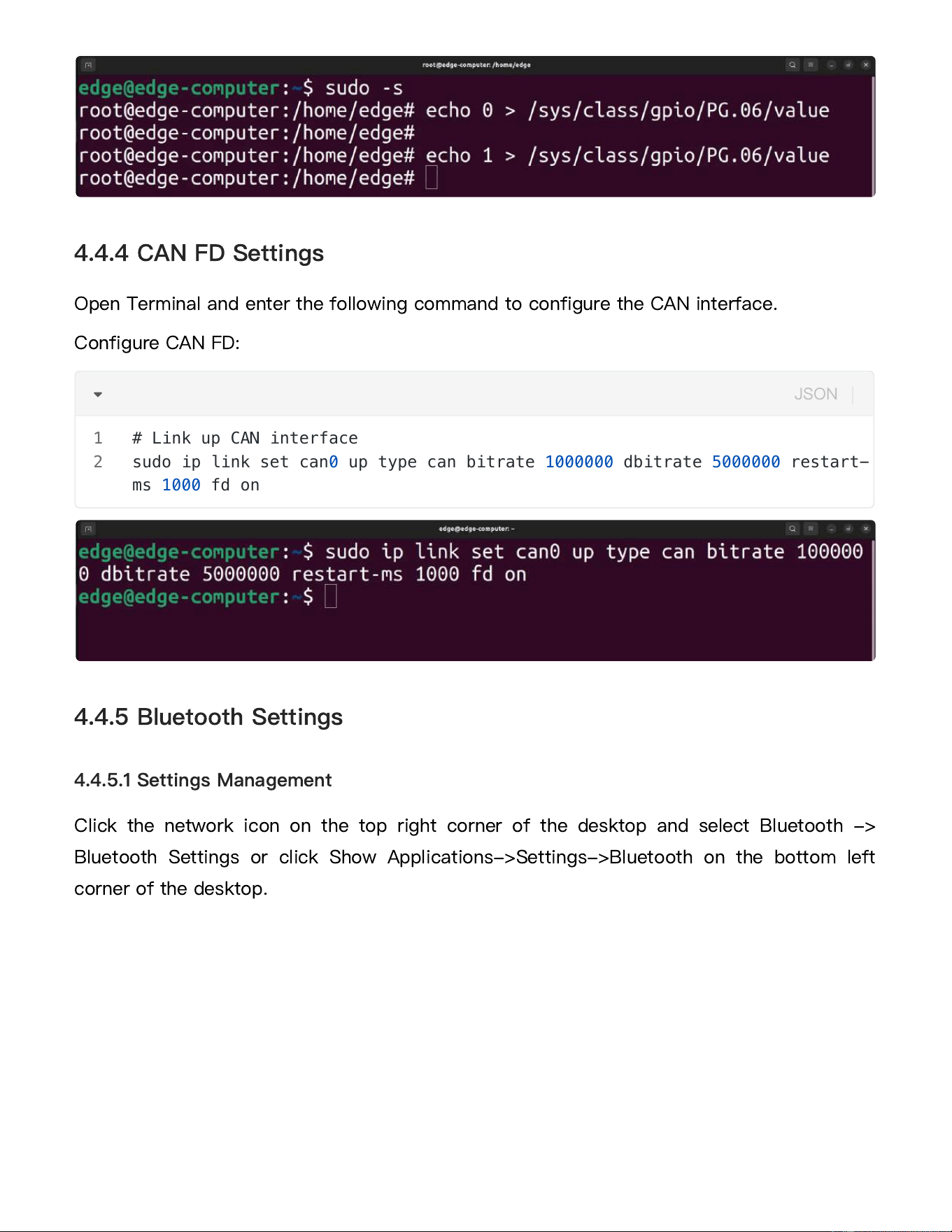
Open Terminal and enter the following command to switch the SIM card.
Switching SIM Card:
4.4.3.2 Switching SIM Card
# Access cellular AT command interface using 115200 baud rate
sudo sdebug /dev/ttyUSB2 115200
# Configure cellular ECM mode
AT+QCFG="usbnet",1
# Save and reboot cellular module
AT+CFUN=1,1
1
2
3
4
5
6
JSON
# Switch to root
sudo -s
# Switch to SIM1
echo 0 > /sys/class/gpio/PG.06/value
# Switch to SIM2
echo 1 > /sys/class/gpio/PG.06/value
1
2
3
4
5
6
JSON
Open Terminal and enter the following command to configure the CAN interface.
Configure CAN FD:
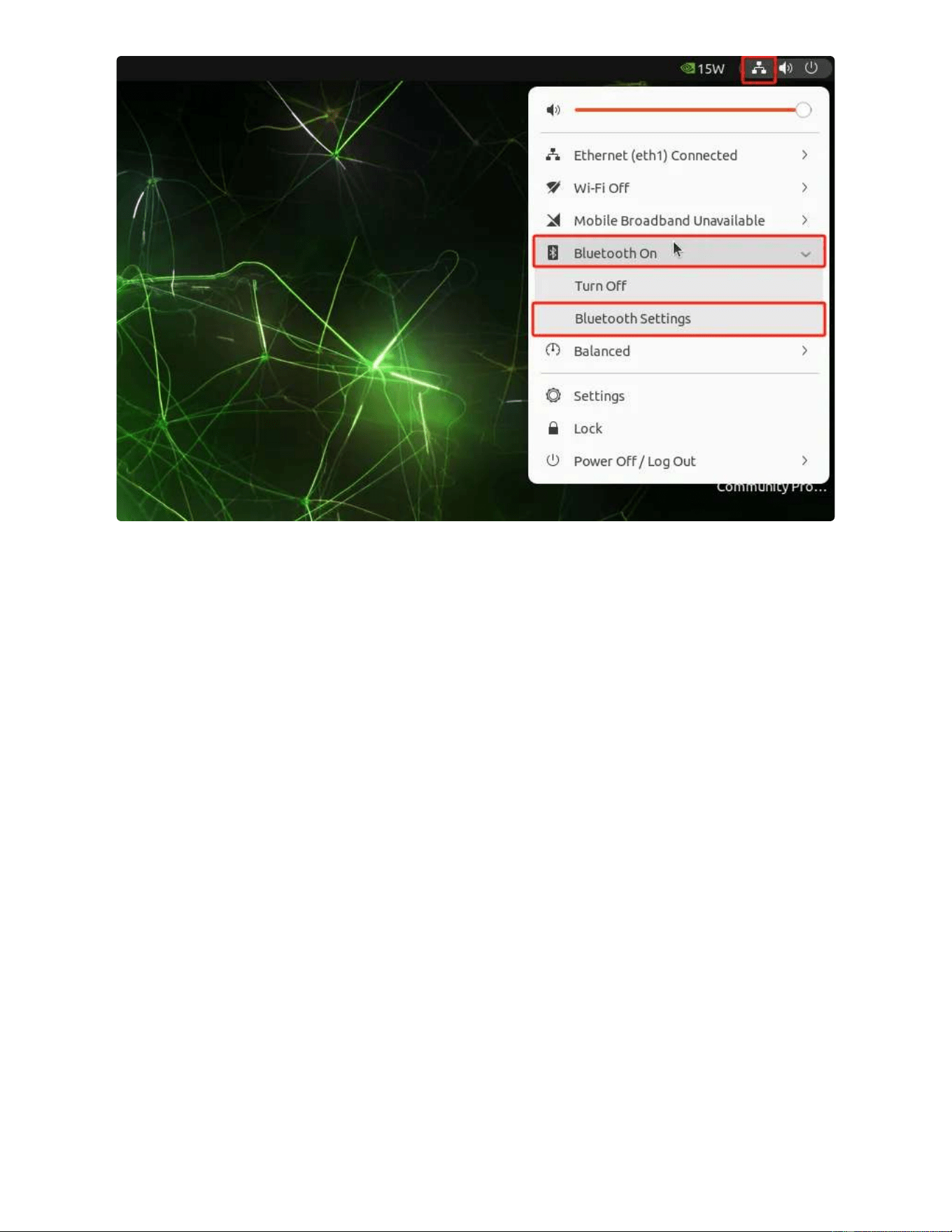
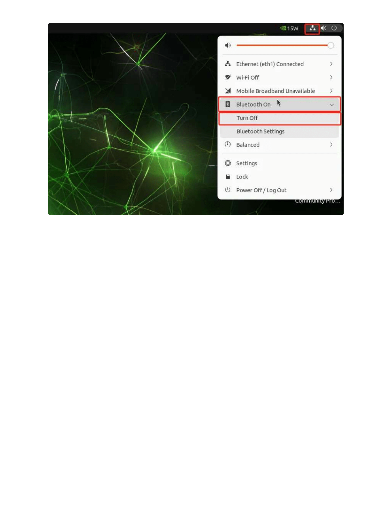
Click the network icon on the top right corner of the desktop and select Bluetooth ->
Bluetooth Settings or click Show Applications->Settings->Bluetooth on the bottom left
corner of the desktop.
4.4.4 CAN FD Settings
4.4.5 Bluetooth Settings
4.4.5.1 Settings Management
# Link up CAN interface
sudo ip link set can0 up type can bitrate 1000000 dbitrate 5000000 restart-
ms 1000 fd on
1
2
JSON
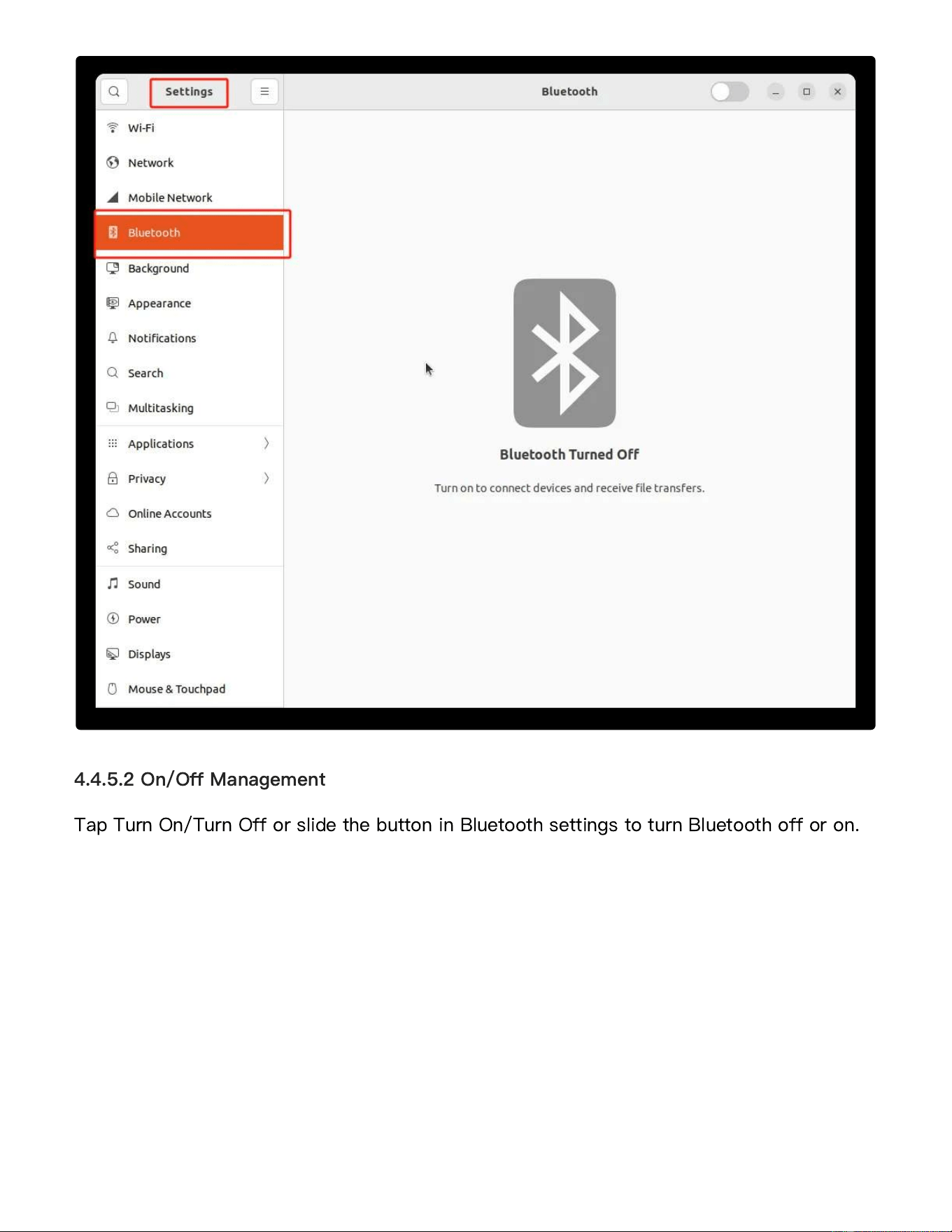
Tap Turn On/Turn Off or slide the button in Bluetooth settings to turn Bluetooth off or on.
4.4.5.2 On/Off Management
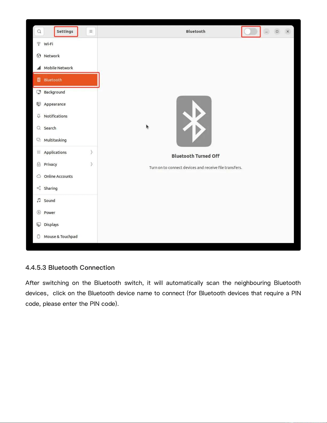
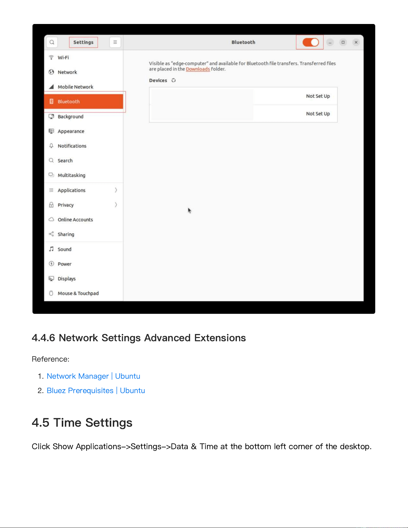
After switching on the Bluetooth switch, it will automatically scan the neighbouring Bluetooth
devices
,
click on the Bluetooth device name to connect (for Bluetooth devices that require a PIN
code, please enter the PIN code).
4.4.5.3 Bluetooth Connection
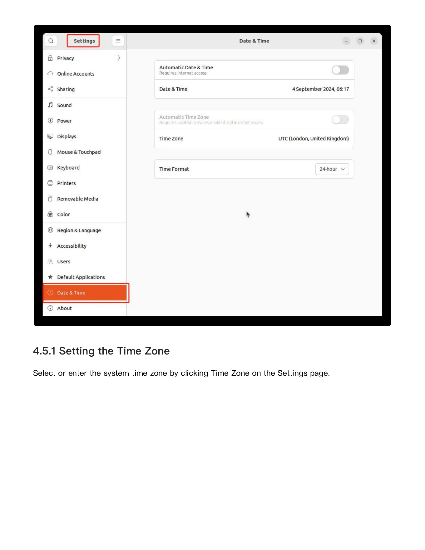
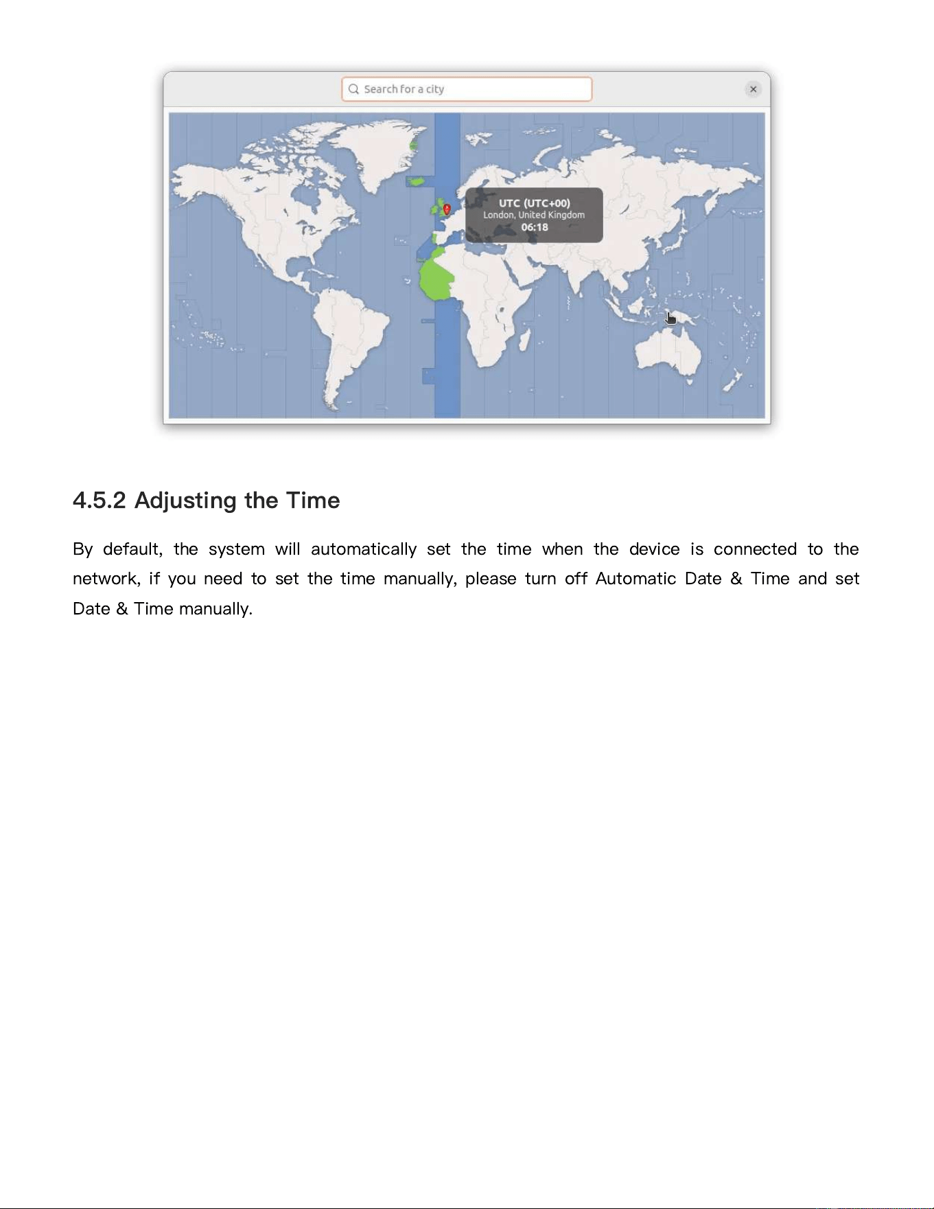
Select or enter the system time zone by clicking Time Zone on the Settings page.
4.5.1 Setting the Time Zone
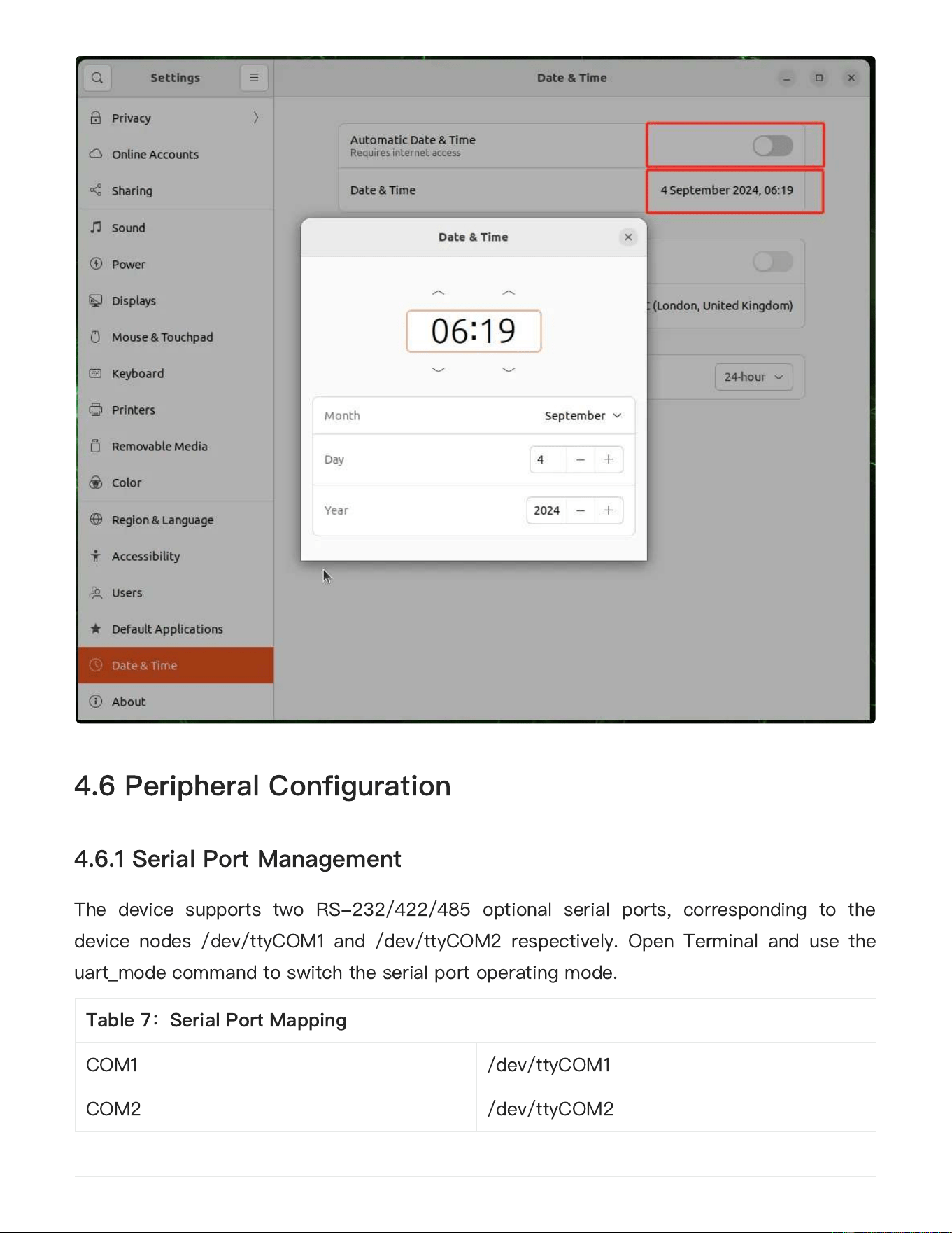
By default, the system will automatically set the time when the device is connected to the
network, if you need to set the time manually, please turn off Automatic Date & Time and set
Date & Time manually.
4.5.2 Adjusting the Time
The device supports two RS-232/422/485 optional serial ports, corresponding to the
device nodes /dev/ttyCOM1 and /dev/ttyCOM2 respectively. Open Terminal and use the
uart_mode command to switch the serial port operating mode.
4.6 Peripheral Configuration
4.6.1 Serial Port Management
Table 7
:
Serial Port Mapping
COM1
/dev/ttyCOM1
COM2
/dev/ttyCOM2
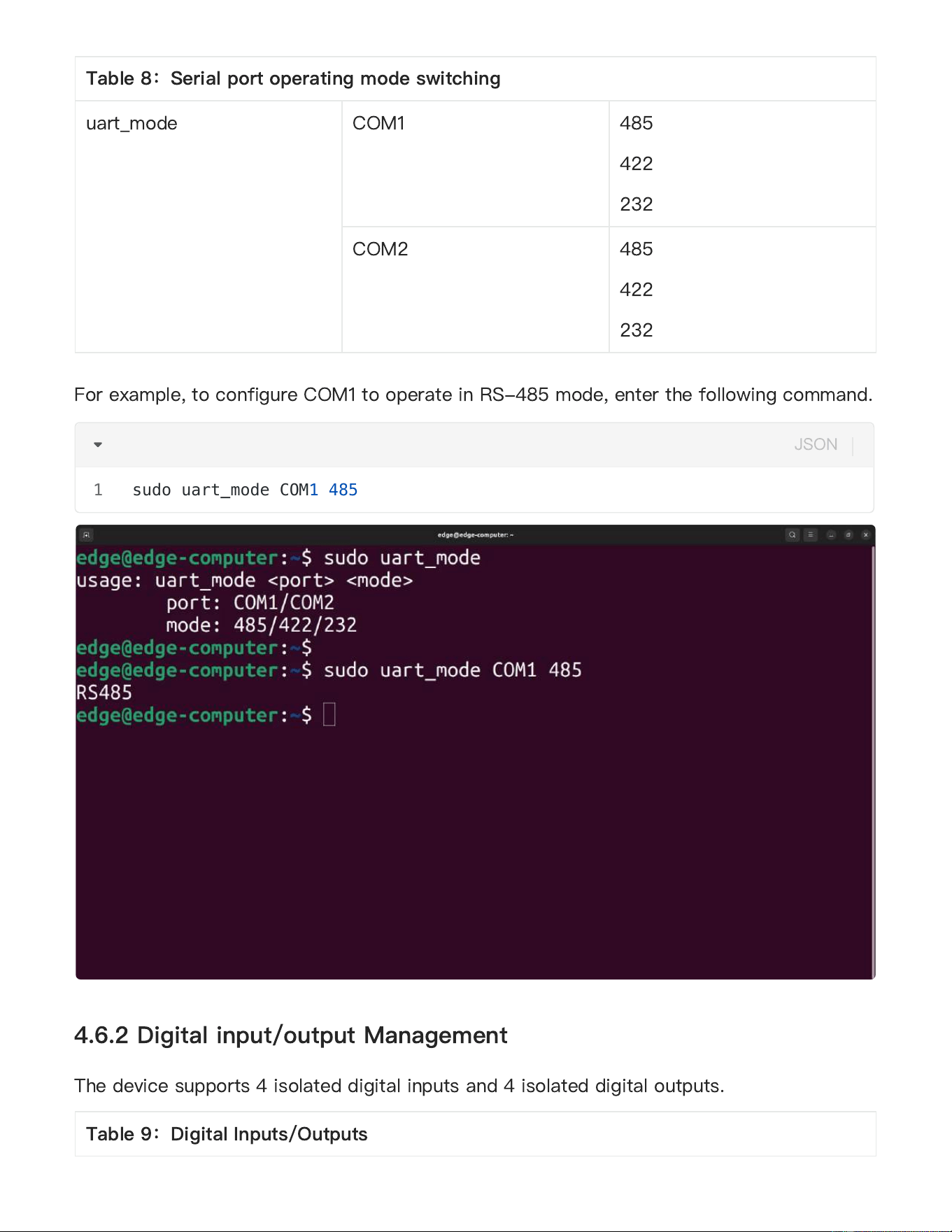
For example, to configure COM1 to operate in RS-485 mode, enter the following command.
The device supports 4 isolated digital inputs and 4 isolated digital outputs.
4.6.2 Digital input/output Management
Table 8
:
Serial port operating mode switching
uart_mode
COM1
485
422
232
COM2
485
422
232
sudo uart_mode COM1 485
1
JSON
Table 9
:
Digital Inputs/Outputs
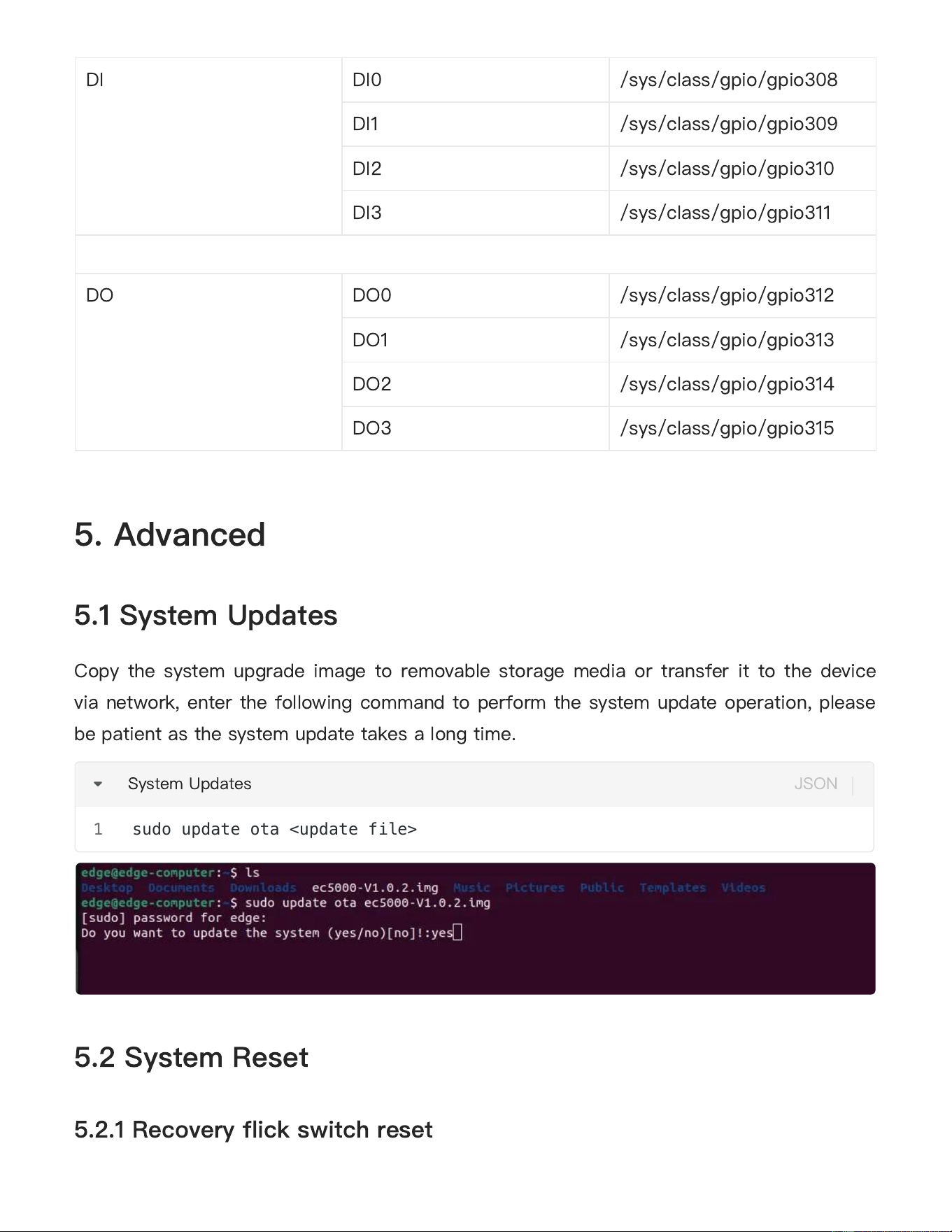
Copy the system upgrade image to removable storage media or transfer it to the device
via network, enter the following command to perform the system update operation, please
be patient as the system update takes a long time.
5. Advanced
5.1 System Updates
5.2 System Reset
5.2.1 Recovery flick switch reset
DI
DI0 /sys/class/gpio/gpio308
DI1 /sys/class/gpio/gpio309
DI2 /sys/class/gpio/gpio310
DI3 /sys/class/gpio/gpio311
DO
DO0
/sys/class/gpio/gpio312
DO1
/sys/class/gpio/gpio313
DO2
/sys/class/gpio/gpio314
DO3
/sys/class/gpio/gpio315
sudo update ota <update file>
1
System Updates
JSON
The device has a Recovery flick switch button under the detachable bezel on the right
panel, press and hold Recovery for 10 seconds during normal system operation and wait
for the system status light to change from blinking to normally lit and release it, the device
will enter the system reset state (restoring the system to the factory state), please refer to
part 2.2.10 for detailed descriptions of the buttons;
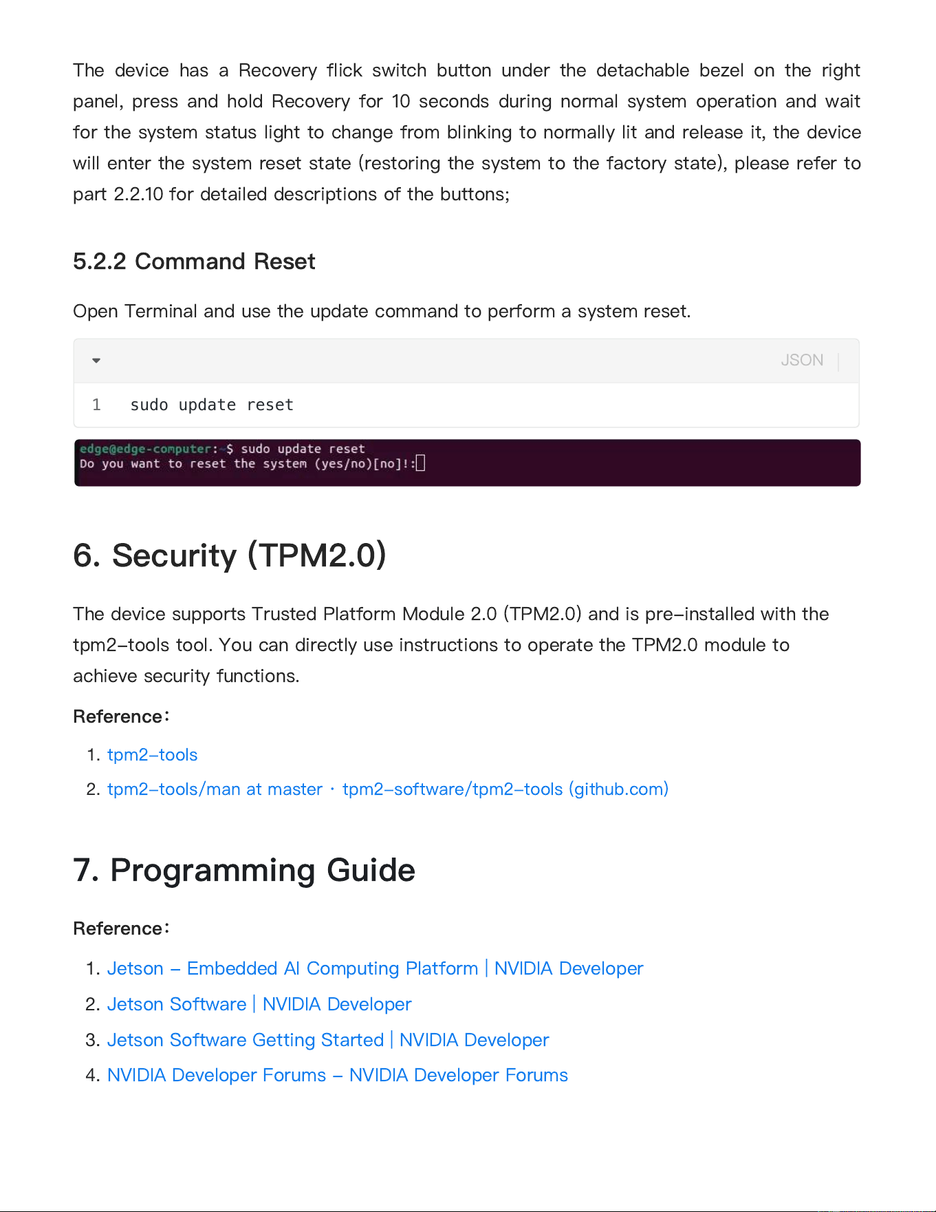
Open Terminal and use the update command to perform a system reset.
The device supports Trusted Platform Module 2.0 (TPM2.0) and is pre-installed with the
tpm2-tools tool. You can directly use instructions to operate the TPM2.0 module to
achieve security functions.
Reference
:
1.
tpm2-tools
2.
tpm2-tools/man at master · tpm2-software/tpm2-tools (github.com)
Reference
:
1.
Jetson - Embedded AI Computing Platform | NVIDIA Developer
2.
Jetson Software | NVIDIA Developer
3.
Jetson Software Getting Started | NVIDIA Developer
4.
NVIDIA Developer Forums - NVIDIA Developer Forums
5.2.2 Command Reset
6. Security (TPM2.0)
7. Programming Guide
sudo update reset
1
JSON

Warning: There
is a button cell battery inside our EC5350, The cautions for its use are as
follows:
1. not available
2. Do not ingest battery, Chemical Burn Hazard, If the button cell battery is swallowed, it can
cause severe internal burns in just 2 hours and can lead to death.
3. Keep new and used batteries away from children. If you think batteries might have been
swallowed or placed inside any part of the body, seek immediate medical attention.
4. The operating temperature of the battery is -20℃ to +60℃, The product should be installed
in an environment that does not exceed this temperature range
5. Disposal of a BATTERY into fire or a hot oven, or mechanically crushing or cutting of a
BATTERY, that can result in an EXPLOSION;
6. Leaving a BATTERY in an extremely high temperature surrounding environment that can
result in an EXPLOSION or the leakage of flammable liquid or gas;
7. A BATTERY subjected to extremely low air pressure that may result in an EXPLOSION or
the leakage of flammable liquid or gas.

53
FCC STATEMENT
This device complies with Part 15 of the FCC Rules. Operation is subject to the following two
conditions:
(1) This device may not cause harmful interference, and
(2) this device must accept any interference received, including interference that may cause
undesired operation.
NOTE 1: This equipment has been tested and found to comply with the limits for a Class B
digital device , pursuant to part 15 of the FCC Rules. These limits are designed to provide
reasonable protection against harmful interference in a residential installation. This equipment
generates, uses and can radiate radio frequency energy and, if not installed and used in
accordance with the instructions, installed and used in accordance with the instructions, may
cause harmful interference to radio communications. However, there is no guarantee that
interference will not occur in a particular installation. If this equipment does cause harmful
interference to radio or television reception, which can be determined by turning the equipment
off and on, the user is encouraged to try to correct the interference by one or more of the
following measures:
- Reorient or relocate the receiving antenna.
- Increase the separation between the equipment and receiver.
-Connect the equipment into an outlet on a circuit different from that to which the receiver is
connected.
-Consult the dealer or an experienced radio/TV technician for help.
NOTE 2: Any changes or modifications to this unit not expressly approved by the party
responsible for compliance could void the user's authority to operate the equipment.
RF Exposure
The equipment complies with FCC radiation exposure limits set forth for an uncontrolled
environment. This device should be installed and operated with minimum distance 20cm
between the radiator & your body.
This transmitter must not be co-located or operating in conjunction with any other antenna or
transmitter. The availability of some specific channels and/or operational frequency bands is
country dependent and firmware programmed at the factory to match the intended destination.
The firmware setting is not accessible by the end user.