ENVIROSUN
®
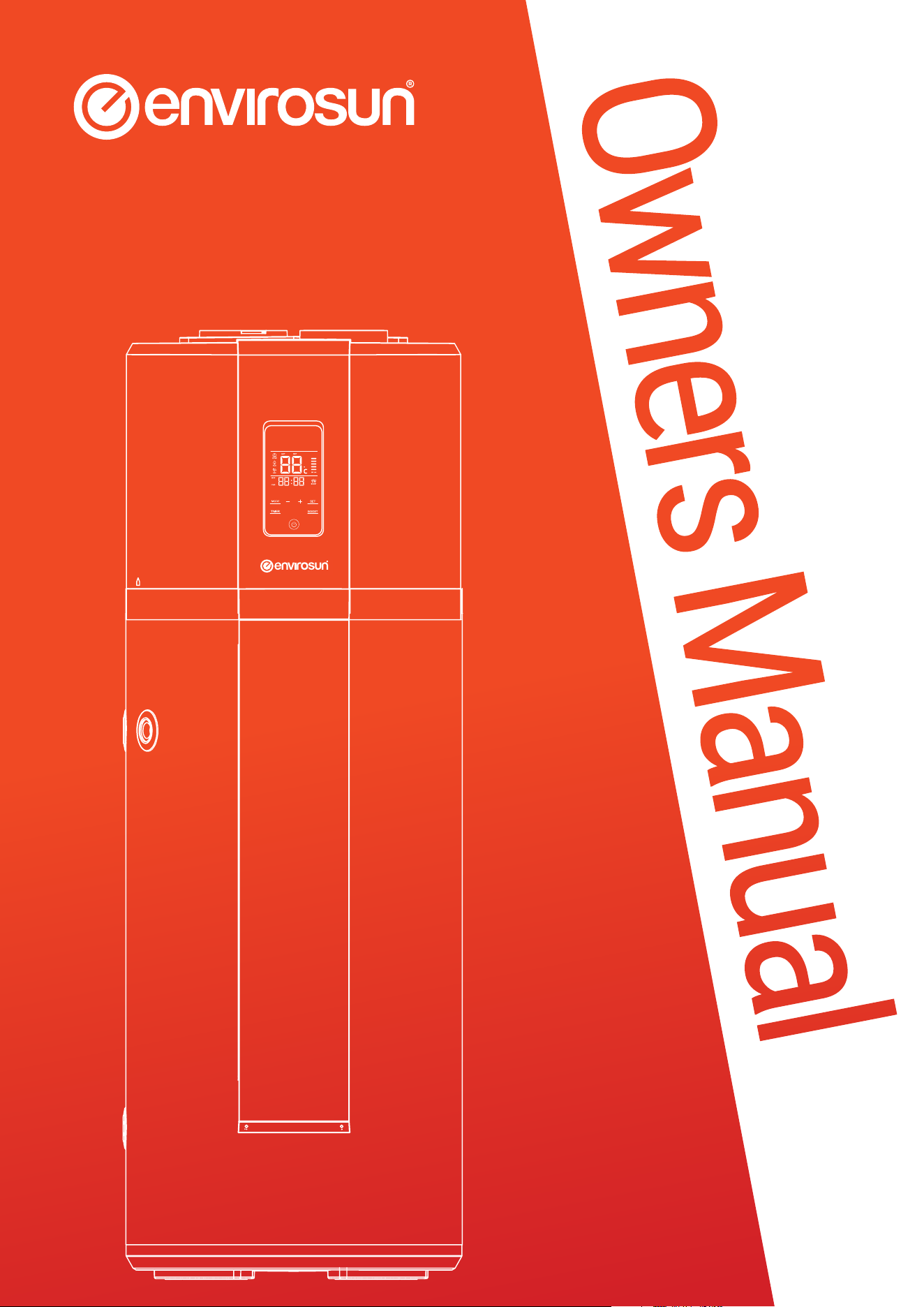
Heat Pump Water Heater
250ES1-15
Owners Manual
UserManual_2023-Envirosun_HP-Plus-Classic.indd 1UserManual_2023-Envirosun_HP-Plus-Classic.indd 1 7/01/2025 8:42:34 AM7/01/2025 8:42:34 AM

Page 2 of 21 ver 250107.08
THIS PAGE INTENTIONALLY LEFT BLANK
UserManual_2023-Envirosun_HP-Plus-Classic.indd 2UserManual_2023-Envirosun_HP-Plus-Classic.indd 2 7/01/2025 8:42:34 AM7/01/2025 8:42:34 AM

ver 250107.08 Page 3 of 21
CONTENTS
IMPORTANT SAFETY INFORMATION ........................................................................................................................................... 4
Interpretation of marks and symbols ............................................................................................................................................... 4
General safety instruction ................................................................................................................................................................ 4
Instructions on transportation and storage ...................................................................................................................................... 4
FUNCTIONING & PRINCIPLE OF OPERATION ................................................................................................................................ 5
SPECIFICATIONS ......................................................................................................................................................................... 6
Overall Dimensions ......................................................................................................................................................................... 7
INSTALLATION INTRODUCTION ................................................................................................................................................... 8
Precautions ..................................................................................................................................................................................... 8
Installation Dimensions .................................................................................................................................................................. 9
Local Standards ............................................................................................................................................................................... 10
Safety .............................................................................................................................................................................................. 10
Water Quality ................................................................................................................................................................................... 10
Supplementary Heat Sources ........................................................................................................................................................... 10
PLUMBING CONNECTIONS .......................................................................................................................................................... 11
Piping Materials ............................................................................................................................................................................... 11
Pressure Reducing Valve ................................................................................................................................................................. 11
Pressure & Temperature Relief Valve .............................................................................................................................................. 12
Cold Water Expansion Relief Valve .................................................................................................................................................. 12
Important Safety Information ........................................................................................................................................................... 12
ELECTRICAL CONNECTIONS ......................................................................................................................................................... 12
Electrical Protection Precautions ..................................................................................................................................................... 12
COMMISSIONING CHECK LIST ...................................................................................................................................................... 13
OPERATION AND FUNCTIONS ....................................................................................................................................................... 14
Display ............................................................................................................................................................................................. 14
Screen lock function ........................................................................................................................................................................ 15
Emergency mode ............................................................................................................................................................................. 15
How to set the timer ........................................................................................................................................................................ 15
Recommended system settings ...................................................................................................................................................... 15
TROUBLESHOOTING ..................................................................................................................................................................... 16
Hot water use higher than anticipated ............................................................................................................................................. 16
Water discharge through the pressure relief valve ............................................................................................................................ 16
MAINTENANCE ............................................................................................................................................................................. 16
Draining and ushing the system ..................................................................................................................................................... 16
Relief valves ..................................................................................................................................................................................... 16
Anode replacement ......................................................................................................................................................................... 17
Condensate discharge pipe ............................................................................................................................................................. 17
CONTACT DETAILS ....................................................................................................................................................................... 17
STANDARD WARRANTY ................................................................................................................................................................ 18
Warranty Terms ............................................................................................................................................................................... 18
Warranty Conditions ........................................................................................................................................................................ 18
Warranty Exclusions ......................................................................................................................................................................... 19
OH&S Disclaimer ............................................................................................................................................................................. 20
INSTALLATION RECORD ............................................................................................................................................................... 21
UserManual_2023-Envirosun_HP-Plus-Classic.indd 3UserManual_2023-Envirosun_HP-Plus-Classic.indd 3 7/01/2025 8:42:35 AM7/01/2025 8:42:35 AM
Page 4 of 21 ver 250107.08
IMPORTANT SAFETY INFORMATION
Interpretation of marks and symbols
WARNING
Information provided with this warning mark relates to activities that are denitely forbidden or dangerous.
Failure to adhere to the instructions may result in damage to the product or users may risk personal danger or injury.
CAUTION
Instructions with this warning mark shall be strictly followed during operation.
They relate to the safety of users and the product.
Instructions with this mark relate to important installation requirements that ensure the correct operation of the device.
General safety instruction
WARNING
The water heater shall be installed in strict accordance with local wiring regulations and equipped with a power supply
containing a ground/earth conductor.
This water heater is not intended for use by young children, inrm persons, or persons lacking relevant skill or experience,
without suitable supervision.
Children should be supervised to ensure they do not play with hot water taps or the water heater.
The unit must be installed by a licensed trade person and in accordance with:
• This Installation & Maintenance Guide
• AS/NZS 3500.4 - “National Plumbing and Drainage Code Hot Water Supply Systems-Acceptable Solutions“
• AS/NZS 3000 - Wiring Rules
• Local authority regulations
• Building Codes of Australia
• Local Occupational Health and Safety (OH&S) Regulations
Do not operate this water heater without the electrical thermostat and over temperature cut-out in the circuit.
This appliance contains uorinated greenhouse gases: R134a/0.9kg. Fluorinated greenhouse gases are contained in
hermetically sealed equipment. Global Warming Potential 100 years (GWP100): 1 430
CAUTION
Personally inspecting or servicing any part of the system is not recommended.
The water heater shall not be installed at places where water drainage is unavailable or impossible.
Instructions on transportation and storage
During transportation or storage, the heat pump water heater shall be packed in the undamaged package to avoid damage to
appearance and performance of the product.
During transportation or storage, the heat pump water heater shall be in the upright position.
Under special conditions, this product may be laid down for a short time/distance as per indication on the side of the package
case. The heat pump water heater, after being laid down, shall be kept in an upright position for more than 4 hours before
starting up.
This symbol on the product or on its packaging indicates that this product is not to be treated as regular household waste.
Instead, it must be taken to a recycling point for electrical equipment. By properly disposing of this product, you are contributing
to the preservation of the environment and the wellbeing of your fellow citizens.
Improper disposal is hazardous to your health and the environment. You can obtain further information on how to recycle thus
product from your municipality, your waste management service or the Envirosun dealer where you purchased the appliance.
UserManual_2023-Envirosun_HP-Plus-Classic.indd 4UserManual_2023-Envirosun_HP-Plus-Classic.indd 4 7/01/2025 8:42:35 AM7/01/2025 8:42:35 AM
ver 250107.08 Page 5 of 21
FUNCTIONING & PRINCIPLE OF OPERATION
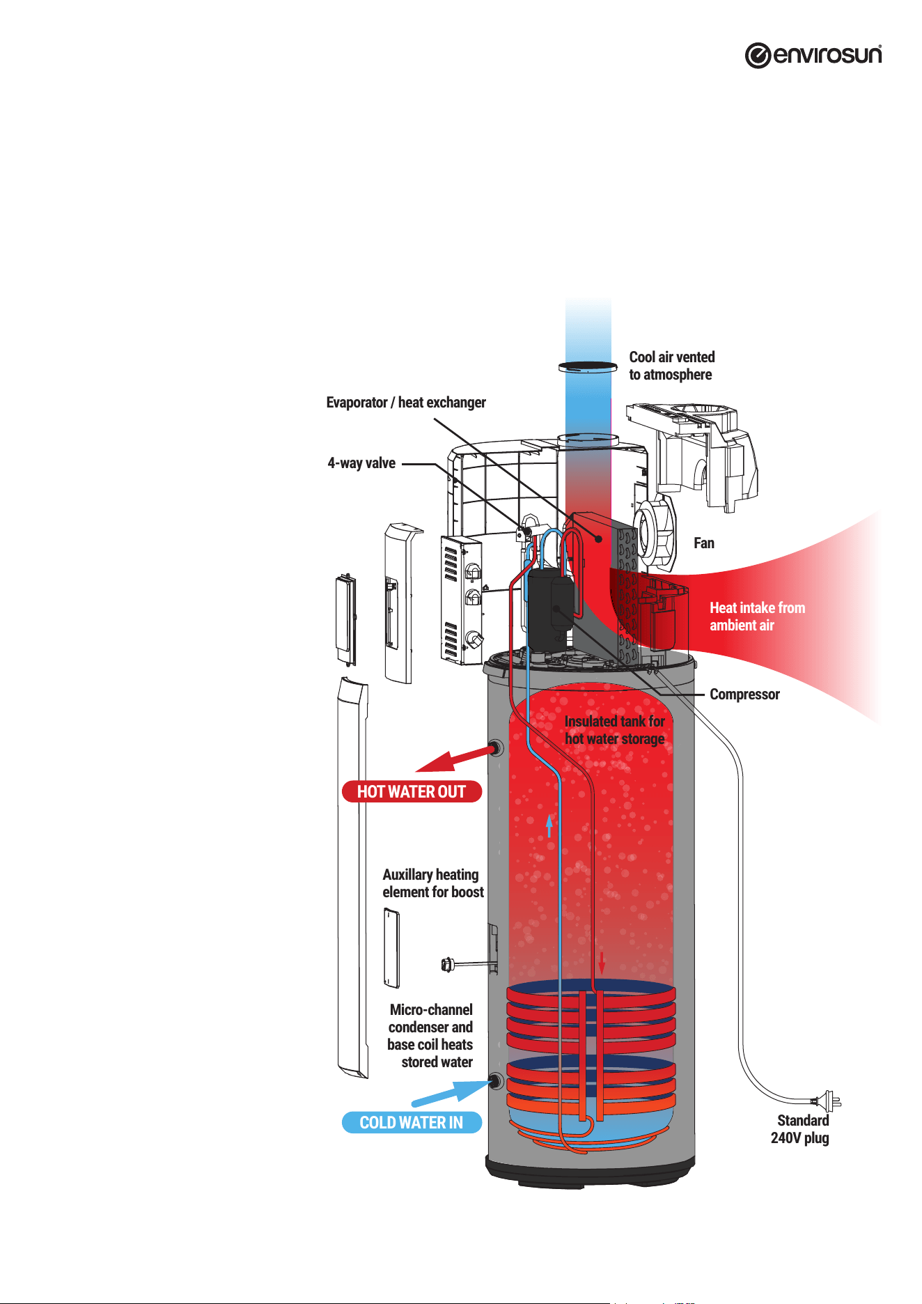
Your Envirosun system is called a heat pump because it collects heat from the ambient air and “pumps” it into the water in the storage vessel. This is
done in much the same way that an air conditioner removes heat from a room and expels it to the outside air.
A refrigerant is used to transfer the heat via a compressor to a heat exchanger wrapped around the storage tank. As the refrigerant delivers its heat to
the water, it cools and condenses, and then passes through an expansion valve where the pressure is reduced, and the cycle starts over. This process,
called the Rankine Cycle, has been used for over a century for refrigeration and air conditioning applications and has been used for energy efcient
water heating for decades.
HOW IT WORKS
To understand the
concept of heat pumps,
imagine a refrigerator
working in reverse.
While a refrigerator removes heat from an
enclosed box and expels that heat to the
surrounding air, a heat pump takes the heat
from surrounding air and transfers it to
water in an enclosed tank.
Heat pump technology makes efcient use
of the heat in the surrounding air, even at
temperatures as low as -7°C.
In fact, the Envirosun system is so efcient
that it can convert 1kW of electricity into
over 4kW of heat.
Heat intake from
ambient air
Standard
240V plug
Insulated tank for
hot water storage
Micro-channel
condenser and
base coil heats
stored water
Cool air vented
to atmosphere
Fan
Compressor
Auxillary heating
element for boost
HOT WATER OUT
COLD WATER IN
4-way valve
Evaporator / heat exchanger
UserManual_2023-Envirosun_HP-Plus-Classic.indd 5UserManual_2023-Envirosun_HP-Plus-Classic.indd 5 7/01/2025 8:42:36 AM7/01/2025 8:42:36 AM
Page 6 of 21 ver 250107.08
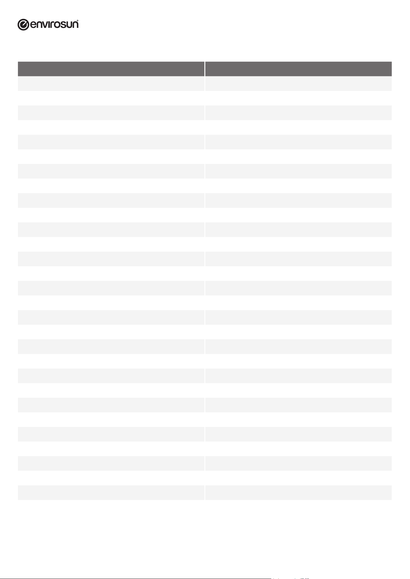
SPECIFICATIONS
Model 250ES1-15
Tank volume 246L
Rated voltage/ frequency 220V~240V/50Hz
Tank rated pressure 0.7MPa
Corrosion protection Magnesium rod
Insulation Protection Rating IPX4
Type of system Monobloc air source heat pump
COP @ 7°C 3.02
COP @ 15°C 3.41
Tapping cycle L
Auxiliary heating element 1500W
Rated power input by heat pump 495W
Maximum power input by heat pump 865W
Maximum power input 1500W
Standby power input/ Pes 35W
Heating up time (7°C) 7.35h
Heating up time (15°C) 6.17h
Default temperature setting 65°C
Temperature setting range - with heater 35°C – 75°C
Max. working pressure of refrigerant 0.8/2.8MPa
Refrigerant type / weight R134a/0.9kg
Sound pressure level 46dBA
STC Zone Zone 1 – 5
Ambient temp. operating range of heat pump -7 – 45°C
*1
Water inlet and outlet connection G3/4"F
Safety valve connection G3/4"F
Drain & Water inlet connection G3/4"F
Product Dimensions (mm) 600 x 629 x 1987
Packing dimension without pallet (mm) 736 x 695 x 2120
Packing dimension with pallet (mm) 736 x 695 x 2250
Net/Gross weight 102/115kg
*1
If the operating ambient temperature is outside of the specied range, the system will use the auxiliary electric heating element to avoid damage
to the heat pump.
UserManual_2023-Envirosun_HP-Plus-Classic.indd 6UserManual_2023-Envirosun_HP-Plus-Classic.indd 6 7/01/2025 8:42:36 AM7/01/2025 8:42:36 AM
ver 250107.08 Page 7 of 21
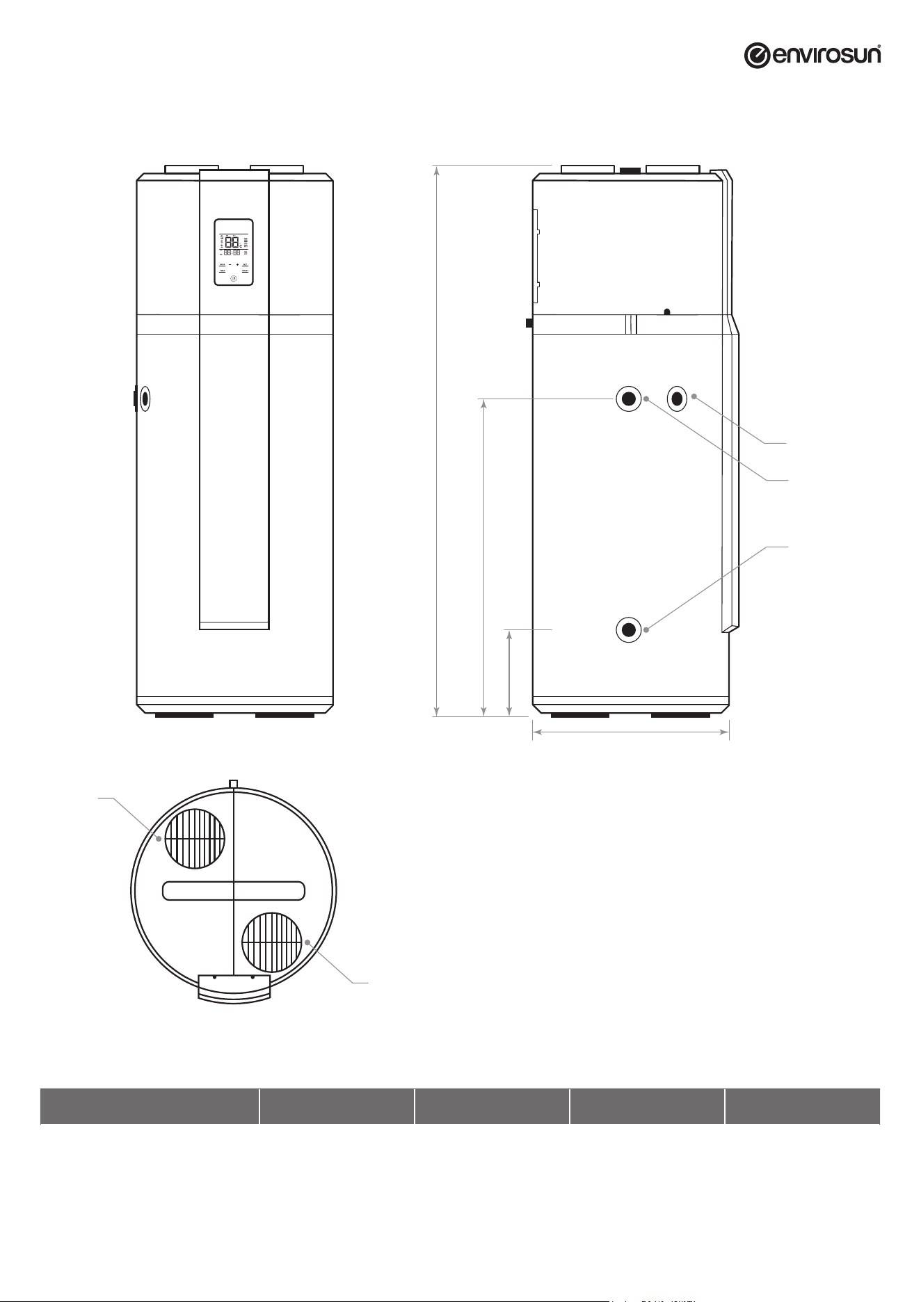
Overall Dimensions
Inlet for Cold
Water/Drain
Outlet
Hot Water
Outlet
Air Outlet
Air Inlet
Safety Valve
Condensate
Outlet
B
C
D
A
Model A B C D
250ES1-15 629 270 1275 1,987
UserManual_2023-Envirosun_HP-Plus-Classic.indd 7UserManual_2023-Envirosun_HP-Plus-Classic.indd 7 7/01/2025 8:42:36 AM7/01/2025 8:42:36 AM
Page 8 of 21 ver 250107.08
INSTALLATION INTRODUCTION
Precautions
• Do not install the water heater in a position where it will be exposed to gas, vapours or dust.
• Install the appliance on a at, solid surface. The surface must support the machine weight and the condensate
water can be drained freely.
• Ensure that noise due to the operation and air ow of the heat pump complies with the relevant regulations.
• Ensure that there is adequate ventilation around the water heater, do not install in an enclosed space.
• Ensure that there is sufcient space around the unit to allow for service and maintenance.
• Ensure that there is no strong magnetic interference present that may affect control systems.
• Ensure that there are no corrosive gases or liquids present near the unit.
• Where ambient temperatures are likely to drop below 0°C ensure that adequate freeze protection is provided.
CAUTION
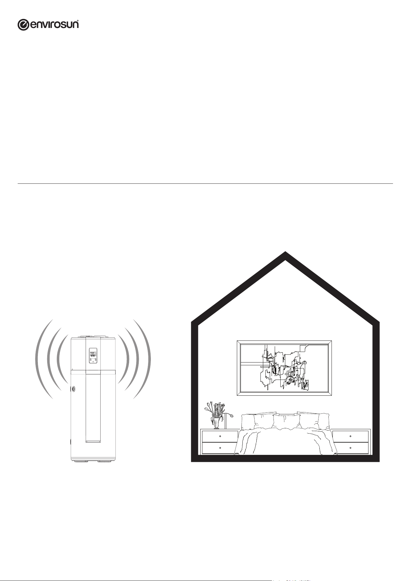
Keep an adequate distance between the water heater and bedrooms.
Your Envirosun system emits very low noise level however there are certain times of the day where any noise may be objectionable. This is especially
the case if the system is located near a bedroom and is running while the occupants are sleeping. It is highly recommended that the system be
programmed to run when noise is not objectionable, for example between 5am and 9pm, or that the system be located away from bedrooms.
UserManual_2023-Envirosun_HP-Plus-Classic.indd 8UserManual_2023-Envirosun_HP-Plus-Classic.indd 8 7/01/2025 8:42:36 AM7/01/2025 8:42:36 AM
ver 250107.08 Page 9 of 21
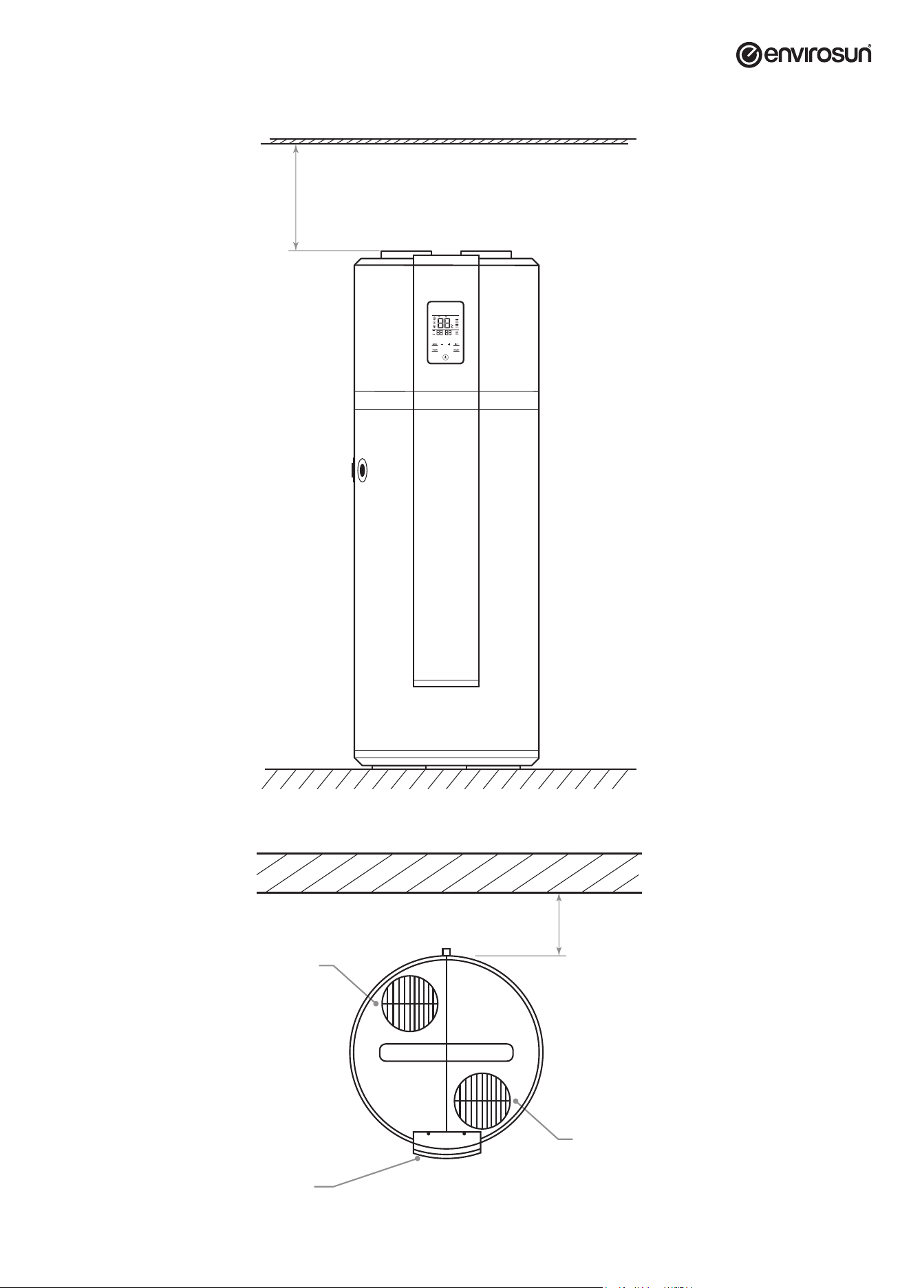
Installation Dimensions
~50mm
~400mm
Air Outlet
Air Inlet
Display
~50mm
~400mm
Air Outlet
Air Inlet
Display
UserManual_2023-Envirosun_HP-Plus-Classic.indd 9UserManual_2023-Envirosun_HP-Plus-Classic.indd 9 7/01/2025 8:42:36 AM7/01/2025 8:42:36 AM

Page 10 of 21 ver 250107.08
Local Standards
The installation shall conform to the Plumbing Code of Australia (PCA). The following standards and regulations must be taken into account when
planning the installation of the Envirosun water heater system.
• AS/NZS 3500.4.2 Notational plumbing and drainage code hot water supply systems – acceptable solutions.
• HB 263-2004 heated water systems plumbing industry commission.
• AS/NZS 3000 Electrical installations (known as the Australian/New Zealand Wiring Rules).
• Any local regulations that govern this type of installation.
• In frost prone areas
Where these instructions and any local regulations are in conict, the local regulations shall prevail.
Safety
Do not commence any aspect of this installation until you have satised yourself that all safety issues have been addressed.
WARNING
THIS APPLIANCE MAY DELIVER WATER AT HIGH TEMPERATURE. REFER TO THE PLUMBING CODE OF AUSTRALIA (PCA),
LOCAL REQUIREMENTS AND INSTALLATION INSTRUCTIONS TO DETERMINE IF ADDITIONAL DELIVERY TEMPERATURE
CONTROL IS REQUIRED.
This installation should only be performed by an approved professional with suitable experience and licenses, authorised
by Energie Group Australia Pty Ltd to conduct the work.
It is imperative that installers adhere to Occupational Health and Safety Guidelines at all times. The installer is responsible for their safety and the
safety of those around them.
Water Quality
Water supply from an unltered water source that may be highly conductive or have a high mineral content may void the system warranty.
Therefore, to ensure water quality guidelines are met, the following characteristics should not be exceeded.
Water Properties Acceptable Levels
Total hardness 200 mg/litre or ppm
Total Dissolved Solids (TDS) 600 mg/litre or ppm
Chloride 250 mg/litre or ppm
Magnesium 10 mg/litre or ppm
Sodium 150 mg/litre or ppm
pH Min 6.5 to Max 8 .5
Electrical conductivity 850 μS/cm
In areas of poor water quality, it is recommended that a softener, conditioner or similar device be tted to the water supply.
WARNING
A breach of this condition may void the warranty in the event of damage caused by water quality
exceeding these characteristics.
Supplementary Heat Sources
If a supplementary heat source is connected to the storage tank, the maximum energy input cannot be more than 10 kW, including the electrical
element. Where greater input is required, a pressure and temperature relief valve with a higher kW rating is to be tted to the storage tank.
Where stove coils are used for supplementary heating the water must be connected in an open vented manner. Refer to Australian Standard AS3500
for more details on acceptable connection solutions.
UserManual_2023-Envirosun_HP-Plus-Classic.indd 10UserManual_2023-Envirosun_HP-Plus-Classic.indd 10 7/01/2025 8:42:36 AM7/01/2025 8:42:36 AM
ver 250107.08 Page 11 of 21
PLUMBING CONNECTIONS
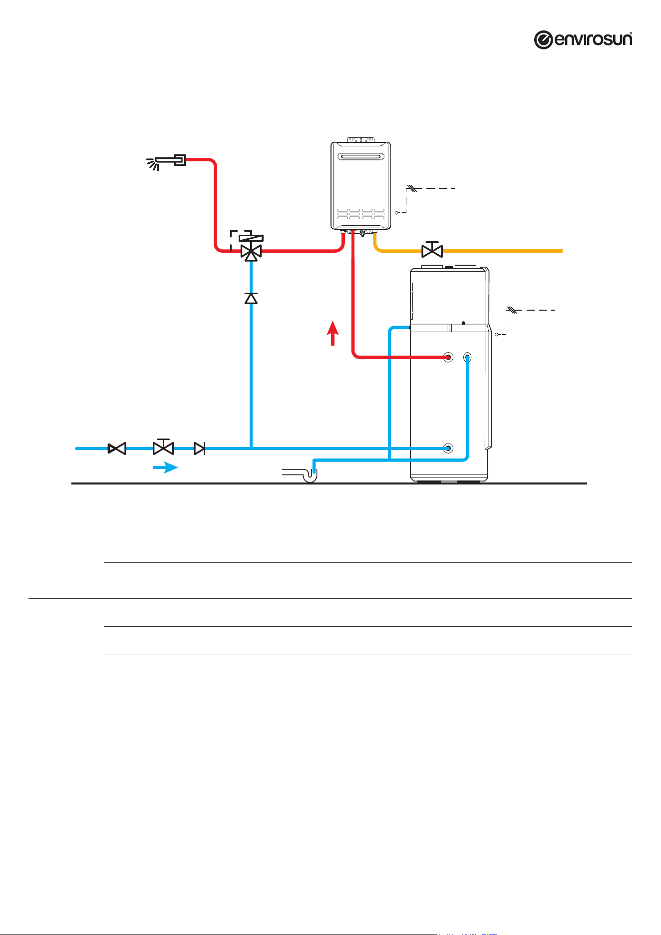
Ensure that the Gas Booster is installed in accordance with all relevant codes and standards.
Stop Valve
Cold Water Inlet
Hot Water
Outlet
Water Outlet
Check Valve
Check Valve
220-240V
50Hz
Condensate
Drain Hole
Water Outlet
of PTR Valve
Thermostatic
Valve
Pressure
Relivef Valve
220-240V
50Hz
Isolation Valve
Gas
Piping Materials
CAUTION
Energie Group Australia Pty Ltd recommends the use of copper pipe, certied to AS1432 Class C, for use in the inlet and outlet
lines to the heat pump water system.
Plastic piping is not to be used for any portion of the water heater system plumbing unless the pipe manufacturer has rated it
for temperatures up to 99°C and a minimum water pressure of 600kPa at these temperatures.
Before making the nal connections, rinse the inlet pipes in order not to introduce metal or other particles into the tank.
The inlet water temperature is suggested to be between 10 - 30°C.
Outdoor water pipes and valves should be properly insulated.
Pressure Reducing Valve
Where the mains water supply pressure is likely to exceed 550 kPa at any time, a 500kPa pressure reducing valve that complies with AS1357 must be
tted to the inlet of the hot water system. This is essential to safeguard the appliance and ensure correct operation.
WARNING
A breach of this requirement may void the warranty in the event of damage caused by excessive pressure.
UserManual_2023-Envirosun_HP-Plus-Classic.indd 11UserManual_2023-Envirosun_HP-Plus-Classic.indd 11 7/01/2025 8:42:37 AM7/01/2025 8:42:37 AM
Page 12 of 21 ver 250107.08
Pressure & Temperature Relief Valve
Remember this valve can discharge very hot water, so carefully consider its location.
Never discharge onto a solid surface like concrete.
CAUTION
1. Fit the 700 kPa/99°C (10 kW) pressure & temperature relief valve supplied in the parts box into G¾”F tank socket;
2. Ensure that the drain line from the pressure and temperature relief has a continuous downslope and falls away
from the valve and towards the ground level to a safe location, terminating above the ground level. Please ensure
that the drain is installed in a place where it cannot be affected by freezing conditions (per AS3500).
Cold Water Expansion Relief Valve
Fit the 600 kPa pressure relief valve in the cold water supply pipe after the check valve, stop cock and (if required) pressure limiting valve.
Important Safety Information
All water heaters have the ability to produce hot water very quickly. To reduce the risk of scald injury it is recommended that a temperature control
valve be tted to the hot water supply pipe work. This valve should be checked every 6 months to ensure its operation and settings remain correct.
Check that the pressure and temperature relief valve drain pipe is not located where it can cause damage if hot water is discharged.
WARNING
This water heater is not intended for use by young children, inrm persons, or persons lacking relevant skill or experience,
without suitable supervision.
Children should be supervised to ensure they do not play with hot water taps or the water heater.
If the hot water system is not used for two weeks or more, a quantity of hydrogen gas, which is highly ammable, may accumulate in the water
heater. To dissipate this gas safely, it is recommended that a hot tap be turned on for several minutes at a sink, basin or bath but not a dishwasher,
clothes washer, or other appliance. During this procedure there must be no smoking, open ame or any other electrical appliance operating nearby.
If hydrogen is discharged through the tap, it will probably make an unusual noise as with air escaping. Do not place hands or any part of your body
beneath the tap during this procedure.
ELECTRICAL CONNECTIONS
CAUTION
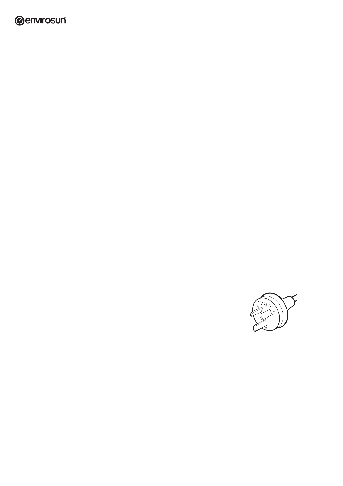
Your heat pump system is equipped with a 10 Amp plug and cord that
enables connection to power via a weatherproof power outlet.
Electrical Protection Precautions
CAUTION
For safe performance this water heater is tted with a thermostat and an over temperature cut-out.
These devices should not be tampered with or removed.
Do not operate this water heater without the electrical thermostat and over temperature cut-out in the circuit.
Electrical connection of water heaters should be performed by a qualied person in accordance with
AS3000 including any current revisions.
UserManual_2023-Envirosun_HP-Plus-Classic.indd 12UserManual_2023-Envirosun_HP-Plus-Classic.indd 12 7/01/2025 8:42:37 AM7/01/2025 8:42:37 AM

ver 250107.08 Page 13 of 21
COMMISSIONING CHECK LIST
System Location — ensure that
F
The location where the base of the water heater is located is sufciently compact
to avoid subsidence when the system is lled with water.
F
Enough room has been allowed for service and maintenance of the water heater.
F
The system has been installed in a location that allows enough ventilation.
F
The location is free from any corrosive materials or chemicals.
F
The location is free from any excessive dust or material that can become airborne.
Water System Piping
F
Temperature and pressure relief valve (PTR) is properly installed with a discharge pipe plumbed to suitable drain.
F
Check that all plumbing connections including piping, valves and ttings are properly installed and free of leaks.
F
The system is completely lled with water and all air is drained from the tank and piping.
F
The tempering valve has been installed per manufacturer’s instructions and the
output water temperature is in the range required by local authorities.
F
The condensate drain line is installed and plumbed to suitable drain.
F
All hot water lines are appropriately insulated and protected from UV degradation.
Electrical Connections
F
The water heater is connected to a supply that has a voltage between 220-240 VAC.
F
All hard wiring complies with all local applicable codes and the requirements of this guide.
F
The water heater and electrical supply are properly grounded.
F
A correctly sized overload protection device has been installed.
UserManual_2023-Envirosun_HP-Plus-Classic.indd 13UserManual_2023-Envirosun_HP-Plus-Classic.indd 13 7/01/2025 8:42:37 AM7/01/2025 8:42:37 AM
Page 14 of 21 ver 250107.08
OPERATION AND FUNCTIONS
Display
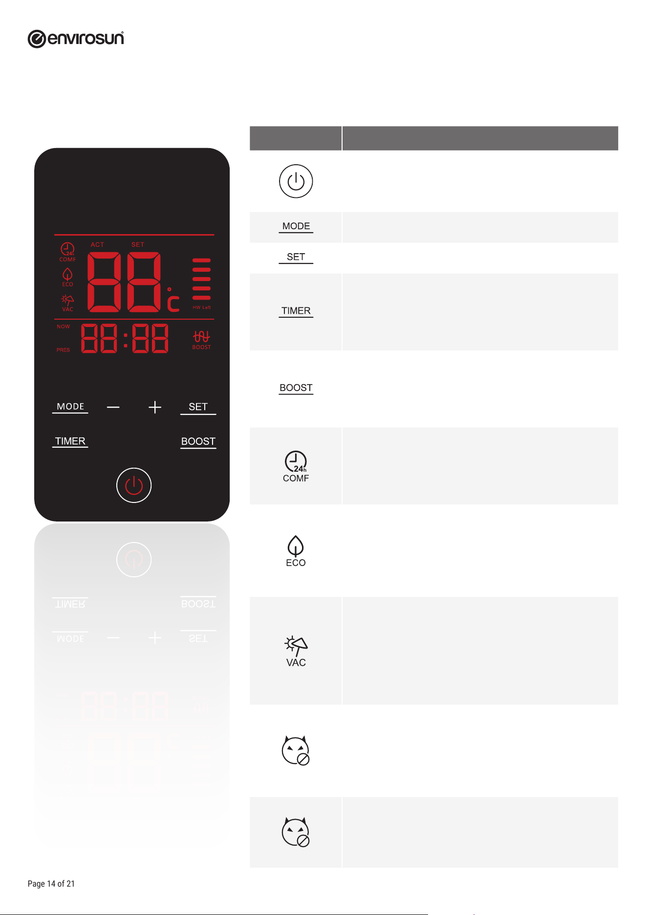
Symbol Description
Power ON/OFF switch.
Working mode selection.
Used to set timer functions and to conrm changes to settings.
Sets the time of day. Press the TIMER button to set hours and
again to set minutes. The system will automatically revert to run
mode after 10 seconds of inactivity.
Note: time is in 24 hour mode.
Boost mode
Auxiliary power is activated in preference to the heat pump. This
will auto reset to heat pump only once the SET temperature is
achieved. This is useful for rapid heating of stored water.
Auto mode
Optimised management of the heat pump for maximum hot
water delivery. Unit will run on demand. Please note that noise
may be objectionable overnight.
ECO (Off-Peak) mode (recommended setting)
In this mode, the unit will run during programmed periods for
example between 5am and 9pm. This mode is essential if you
have solar power installed in order to maximise free energy
utilization. See section on recommended settings.
Holiday mode
If you are planning to be on holiday, you can set your system to
turn on the day before you are due to return. Select this mode
and use the +/- keys to enter the number of days that you will be
away. The system will turn on at midnight on the last day of your
holiday to ensure hot water upon your return.
Anti-legionella
To sanitise your stored water against legionella, the system
will automatically turn on once every 7 days and raise the
temperature to 63°C. Model 250ES-HC-1 has a temperature set
point of 65°C and does not require weekly legionella control.
This display gives you an indication of how much hot water
capacity is available in your system.
UserManual_2023-Envirosun_HP-Plus-Classic.indd 14UserManual_2023-Envirosun_HP-Plus-Classic.indd 14 7/01/2025 8:42:37 AM7/01/2025 8:42:37 AM

ver 250107.08 Page 15 of 21
Screen lock function
To avoid unintended changes to the control system, there is a screen lock function that may have been activated during installation and commissioning.
This function allows the display of temperature however disables the input keys. The normal operation of the system is not affected in this mode.
To enable or disable this function, press the Timer and Boost function at the same time for 6 seconds at which time the buzzer will sound twice
indicating that the function is enabled/disabled.
Emergency mode
If there is a component failure where the heat pump system faults and will not automatically reset, this function will prioritise the electrical heating
system to ensure continuity of hot water supply. If this is necessary, you should contact your Envirosun Dealer or call the number in the rear of this
manual to request service to rectify the fault.
In the period between identifying the fault and a technician attending, the Emergency Mode will ensure hot water supply.
If the system has failed, the buzzer will sound 3 times and a fault code will be displayed. Take note of the fault code so you can advise our service
staff. Press the BOOST button for 10 seconds to enable Emergency Mode. The system will now operate with normal temperature control and safety
functions until the fault can be rectied by trained staff.
Please note that there are no user serviceable parts inside the system housing and no attempt should be made to repair the system without prior
approval. Removal of the top casing may present danger and will void warranty.
How to set the timer
Step 1: Press the TIMER button and use the +/- to set the time of day hours. Press the TIMER button again button the time of day
minutes. After 10 seconds, the screen will revert to RUN mode.
Step 2: With the unit on, press the MODE button to select ECO mode.
Step 3: Press SET to select L1 timer START time. Use the +/- to set the start time hours. Press SET and use the +/- to set the start
time minutes.
Step 4: Press SET to select L1 timer STOP time. Use the +/- to set the stop time hours. Press SET and use the +/- to set the stop
time minutes. After 10 seconds, the system will automatically revert to RUN mode.
Note: There is an additional timer setting, L2, which enables a second timed period. This is generally not required.
You have now set the START and STOP time and time of day. Whilst in ECO mode, the system will only run between the programmed times. Whilst the
running noise level of the Envirosun system is quite low, it is not advisable to allow the unit to run during the night when ambient noise levels are low.
If solar power is installed on the property, the settings below will maximise the use of free energy.
Recommended system settings
No Solar Power Installed Small family START 06:00 STOP 19:00 Temperature 55°C
Large family START 05:00 STOP 21:00 Temperature 60°C
Solar Power Installed Small family START 07:00 STOP 18:00 Temperature 60°C
Large family START 06:00 STOP 18:00 Temperature 65°C
For commercial applications or where residential hot water demand is greater than normal, we suggest the high capacity model 250ES-HC-1.
UserManual_2023-Envirosun_HP-Plus-Classic.indd 15UserManual_2023-Envirosun_HP-Plus-Classic.indd 15 7/01/2025 8:42:38 AM7/01/2025 8:42:38 AM

Page 16 of 21 ver 250107.08
TROUBLESHOOTING
If there is not enough hot water we recommend that the following points are considered as part of the service call. The most obvious reasons for a
lack of hot water could be one of the following.
Hot water use higher than anticipated
Often the hot water usage of showers, washing machines and dishwashers is underestimated by the customer. Review these appliances to determine
if the daily usage is greater than the storage volume of the water heater. Depending on the model of your system, your tank contains a volume of either
200 or 250L of hot water. If the demand exceeds the stored volume, there may be periods where the water temperature is slightly lower than normal.
It is also advisable to inspect hot water tap washers etc. for leakage and replace if necessary.
Water discharge through the pressure relief valve
All Envirosun heat pump water heaters have two pressure valves located within the system conguration. The cold water expansion control valve
(ECV), located in the cold water supply pipe, may release a small amount of water from time to time during the heating cycle of the system. The water
discharge is water expanding due to the heating process. Normally the discharge will be less than 10 litres per day. The pressure & temperature valve,
located on the storage tank, may also release a small expansion discharge.
It is normal for the Expansion Control Valve (ECV) to drip water when heating. If there is a discharge of more than 10 litres per day from any of the
systems valves, it indicates there may be a problem with the valve or an increased water supply as soon as possible.
UserManual_2023-Envirosun_HP-Plus-Classic.indd 16UserManual_2023-Envirosun_HP-Plus-Classic.indd 16 7/01/2025 8:42:38 AM7/01/2025 8:42:38 AM

ver 250107.08 Page 17 of 21
MAINTENANCE
The Envirosun heat pump water heater is designed so that there is little to do in the way of regular system maintenance.
WARNING
Personally inspecting or servicing any part of the system is not recommended.
Shut down the machine and cut off the power before any work commences.
Maintenance operations are important to guarantee optimum performance and extend the life of the appliance.
Draining and ushing the system
CAUTION
The system must be completely drained of water before any plumbing work is commenced. This will prevent damage to the
storage tank in the event of a vacuum or excessive pressure forming at the storage tank.
The Envirosun heat pump hot water system should be drained and ushed every ve years during a major service of the unit.
1. Turn off and isolate the power supply to the electrical element.
2. Turn off the water supply to the water heater.
3. Release excess pressure from the tank by manually opening the pressure & temperature relief valve.
4. Disconnect the cold water supply pipe connection to the tank.
5. Fit a ½" exible drain pipe to the cold connection at the tank. Place the open end of the drain hose in a
location where it is safe for the hot water to drain away from the tank.
6. Manually open the pressure & temperature relief valve which will allow air into the tank and the water within
the tank will ow out via the exible drain pipe tted to the cold inlet connection. Hold the valve open until
the tank is empty.
Relief valves
The lever on the relief valves should be operated at least every six months. Failure to do so may result in failure of the tank.
If water does not discharge freely from the valves they should be checked and possibly replaced. The relief valves and relief
valve drain lines must not be blocked. Some water may discharge during each heating cycle.
Every ve years all safety valves should be replaced to ensure the continued life and operational safety of the system. In
locations where the potable water has a Total Dissolved Solids (TDS) of greater than 600ppmn it is recommended to replace
all safety valves every three years.
Anode replacement
The high quality vitreous enamel lined, low carbon steel tank has two sacricial anodes for long tank life. These anodes should
be inspected every few years and replaced when they have worn out. As a minimum it is recommended that the anodes be
changed every ve years.
Condensate discharge pipe
Check the pipe regularly for cleanliness. Any obstruction may cause poor condensate ow or cause the accumulation of water
in the heat pump plastic base.
UserManual_2023-Envirosun_HP-Plus-Classic.indd 17UserManual_2023-Envirosun_HP-Plus-Classic.indd 17 7/01/2025 8:42:38 AM7/01/2025 8:42:38 AM

Page 18 of 21 ver 250107.08
STANDARD WARRANTY
Warranty Terms
This warranty is given by Energie Group Australia Pty Ltd in relation to Envirosun Heat Pump Hot Water Systems (the Product).
The benets conferred by this warranty are in addition to all other legal rights and remedies of the Customer in respect of the Product. Given
installation and application is in accordance with the manufacturer’s specications and instructions, the Product and components are warranted by
Envirosun for the cost of labour and components in the event of defects arising from faulty materials and/or workmanship in accordance with the
warranty conditions and exclusions stated in this document.
Where the Product is installed outside the boundaries of a Capital City Metropolitan area or where the Product is installed outside a 25km radius of a
Envirosun Dealer business address, the cost of transport, insurance and travelling will be charged to the consumer.
For all new Product purchases through public sales auctions, internet and/or other electronic sales auctions or remote offerings, the warranty for the
Product is the responsibility of the dealer or reseller of the Product, and not of Envirosun.
Warranty of the Product will remain with the Product for the warranty coverage period.
Warranty Conditions
The initial point of contact for all Warranty claims is the Envirosun Dealer from whom the Product was purchased.
All warranty claims must be reported to Envirosun no later than 14 days from the date the fault is reported to the Envirosun Dealer. All terms of
this warranty are effective from the date of installation of the Product and the attending service person reserves the right to verify this date by
requesting a copy of the certicate of compliance
1
, installation record issued by an appropriately qualied installer or proof of purchase prior to the
commencement of any warranty work.
The Product must have been installed, commissioned, serviced, repaired and removed by a licensed gastter or plumber in accordance with the
manufacturer’s installation instructions, current AS/NZS 3000, AS/NZS 3500, AS/NZS 5601, local regulations and municipal building codes by
persons authorised by local regulations to do so. Cost of labour or materials to remedy an installation that does not comply with these requirements
will be at the express cost of the installer.
The Product must be operated and maintained in accordance with Envirosun’s operating instructions. This warranty only applies to the Product as
supplied by Envirosun and does not apply to any additional electrical and/or plumbing parts supplied by the installer. Where the appliance has not
been sited in accordance the installation instructions or installed such that normal service access is difcult, a service charge may apply. If, at the
discretion of the attending service person, access with is assessed as dangerous, service will be refused.
Any work required to gain reasonable access to the appliance will be chargeable to the customer by the attending service person including, but not
limited to, removal of cupboards, doors, walls, or the use of special equipment to move components to oor level.
The Product is covered for the indicated period from the date of installation. Should a part of the complete Product be replaced during this period,
only the balance of the original warranty will continue to remain effective.
This warranty applies to the Product when it is connected directly to a reticulated water supply from a state approved water utility.
This warranty does not apply if the Product is connected to any alternative water supplies if the water chemistry and impurity levels of alternative
water supplies exceed the limits specied in the Water Properties Table on page 10.
Examples of alternative water supplies include private bore water, water from private dams and water supplied from a reticulated water supply but
where the water chemistry is deliberately altered before supplying the water heater. Should the Product be installed in a regional location where
regular ushing is required due to sediment build-up, the drain cock for ushing must be tted at the time of installation at customer expense. A
warranty will apply to rain water tanks, as alternative water supply, ONLY in circumstances where rain water is ltered and free of any physical or
sediment debris and water quality does not exceed the limits specied in the Water Properties Table on page 19.
Component manufacturers are at liberty to alter the design or construction of the components notwithstanding that the Product may have been sold
by description or sample, even though alterations made have been introduced from the date of contract and the date of delivery provided that the
Products are of the same or similar quality and are t for the purposes for which they are purchased. Such alterations shall not constitute a defect in
design or construction under this warranty.
Envirosun reserves the right to alter the design or construction of the Product within allowance of the relevant Standard(s), industrial and State and
Territory legislation without notice. Envirosun warrants to the original purchaser, or for Product purchased from a Reseller, to the original end user,
that the Product will be free from any defects in materials and workmanship from the date of shipment or invoice or, if longer, the period stated in this
policy in accordance with the warranty terms in Table 2.
UserManual_2023-Envirosun_HP-Plus-Classic.indd 18UserManual_2023-Envirosun_HP-Plus-Classic.indd 18 7/01/2025 8:42:38 AM7/01/2025 8:42:38 AM

ver 250107.08 Page 19 of 21
During the warranty period, Envirosun will at its option apply one of the three following remedies:
i. provide replacement parts necessary to repair the Product,
ii. replace the Product with same Product or similar approved newer design,
iii. refund the amount purchaser paid, LESS DEPRECIATION, upon its return.
Envirosun or an Envirosun Dealer will provide labour to resolve warranty issues during the warranty period. Repair service shall be available at the
purchaser’s location. Envirosun will determine how and where repair services are provided, and the purchaser may, at Envirosun’s reasonable cost, be
required to deliver product to an authorised location.
Replacement parts and/or Products will be new or serviceably used, comparable in function and performance to the original part or Product and
warranted for the remainder of the original warranty period. Purchasing additional Products from Envirosun does not extend your warranty period.
If Envirosun requires the return of defective parts/Products, the Envirosun Dealer/purchaser shall return them within 14 days of receiving replacement
parts. Failure to return defective parts will attract charges for replaced parts/system and their shipment to the Envirosun Dealer/purchaser.
Envirosun offers the following Warranty Terms on all models:
Component
Warranty Coverage
Parts Warranty Labour Warranty
Tank Cylinder 5 year 1 year
Compressor 5 year 1 year
Electrical element 1 year 1 year
Sacricial anode, PTR valve, ECV 1 year 1 year
Installer supplied valves and ttings N/A N/A
Warranty Exclusions
The following exclusions may cause the warranty to become void, and may incur a service charge and cost of parts that may be required.
1. Accidental damage, failure due to misuse, abuse and accidents.
2. Failure due to incorrect installation and/or attempts to repair the Product other than by an Envirosun Dealer or approved service
personnel.
3. Failure to install, commission, service, repair and remove the Product in accordance with the manufacturer’s installation instructions,
current AS/NZS 3000, AS/NZS 3500, AS/NZS 5601, local regulations and municipal building codes by persons authorised to do so.
4. Failure due to use of parts other than Envirosun branded/approved parts.
5. Where the tank or piping system leaks or fails to operate normally due to frost or freezing.
6. Where the Product component has failed directly or indirectly as a result of excessive water pressure, negative pressure (partial
vacuum), corrosive atmosphere, faulty plumbing and/or electrical wiring, or major variations in electrical energy supply.
7. Where the water stored in the cylinder exceeds at any time levels as detailed in this document.
8. Any serial tags/stickers on any of the components are removed or defaced.
9. The Product is relocated from its original point of installation.
10. This warranty does not cover:
a. claim for damage to walls, foundations, gardens, etc. or any other consequential loss or inconvenience either directly or
indirectly due to leakage from the water heating system or any other matter related to the system or its operation.
b. the effects of sludge/sediment as a result of connection to a water supply from suitably ltered or treated sources e.g. spring,
dam, bore or river.
11. Consequential damage or any incident caused by a breach of the requirements as set out in this document.
12. Our goods come with guarantees that cannot be excluded under the Australian Consumer Law. You are entitled to a replacement
or refund for a major failure
13. and for compensation for any other reasonably foreseeable loss or damage. You are also entitled to have the goods repaired or
replaced if the goods fail to be of acceptable quality and the failure does not amount to a major failure.
UserManual_2023-Envirosun_HP-Plus-Classic.indd 19UserManual_2023-Envirosun_HP-Plus-Classic.indd 19 7/01/2025 8:42:38 AM7/01/2025 8:42:38 AM

Page 20 of 21 ver 250107.08
OH&S Disclaimer
Envirosun and its Authorised Dealers work with and recommend various installation and plumbing companies to install, test and certify correct
operation of solar hot water systems or the Product. Envirosun is a supplier of systems only.
Each installation must be covered by the installer’s insurances, commercial terms and conditions and by the applicable OH&S legislation. Each person
that installs assembles or services must comply with all OH&S requirements relevant to the type of work being conducted including, but not limited
to, plumbing work, work on heights exceeding 2.5m and electrical work.
The customer must ensure that it complies with all its OH&S obligations. This warranty will be void if these conditions are not met.
CONTACT DETAILS
For further information, please call one of the following phone numbers from anywhere in Australia:
Energie Group Australia Pty Ltd For after sales service: 1300 825 143
For sales or new product: 1300 314 173
www.energiegroup.au
Head Ofce Energie Group Australia Pty Ltd
460 Victoria Road
Malaga WA 6090
UserManual_2023-Envirosun_HP-Plus-Classic.indd 20UserManual_2023-Envirosun_HP-Plus-Classic.indd 20 7/01/2025 8:42:38 AM7/01/2025 8:42:38 AM
ver 250107.08 Page 21 of 21
INSTALLATION RECORD
PLEASE COMPLETE THIS PAGE AS A RECORD OF THE INSTALLATION DETAILS FOR YOUR REFERENCE TO
DETERMINE WHEN THE SYSTEM IS DUE FOR SERVICE OR IF A WARRANTY MATTER SHOULD ARISE.
SCAN THE QR CODE WITH YOUR PHONE AND REGISTER YOUR WARRANTY ONLINE.
Energie Group Pty Ltd
ABN 50 166 500 787
460 Victoria Road
Malaga WA 6090
IMPORTANT!
REGISTER YOUR
WARRANTY
............................................................................................................................................................................................................................................
Owner Name
............................................................................................................................................................................................................................................
Installation Address
....................................................................................................................
Suburb
......................................................................................................................
State
.......................................................
Telephone (Home)
.......................................................
(Work)
......................................................................................................................
Email
.............. / .............. / ....................
Date
....................................................................................................................
System Model Number
....................................................................................................................
Tank Serial Number
............................................................................................................................................................................................................................................
Installer Name
............................................................................................................................................................................................................................................
Installer Address
....................................................................................................................
Installer Telephone
............................................................................................................................................................................................................................................
............................................................................................................................................................................................................................................
Comments
....................................................................................................................
Customer Signature
......................................................................................................................
Installer Signature
.............. / .............. / ....................
Date
UserManual_2023-Envirosun_HP-Plus-Classic.indd 21UserManual_2023-Envirosun_HP-Plus-Classic.indd 21 7/01/2025 8:42:38 AM7/01/2025 8:42:38 AM