
McIntosh Laboratory, Inc. 2 Chambers Street Binghamton, New York 13903-2699 Phone: 607-723-3512 www.mcintoshlabs.com
PS2KPS2K
POWERED SUBWOOFER
OWNER’S MANUAL

2
Thank You from all of us at McIntosh
You have invested in a precision instrument that
will provide you with many years of enjoyment.
Please take a few moments to familiarize yourself
with the features and instructions to get the
maximum performance from your equipment.
If you need further technical assistance, please
contact your dealer who may be more familiar with
your particular setup including other brands. You
can also contact McIntosh with additional questions
or in the unlikely event of needing service.
McIntosh Laboratory, Inc.
2 Chambers Street
Binghamton, New York 13903
Technical Assistance (607) 723-3512
Fax (607) 724-0549
Customer Service (607) 723-3515
Fax (607) 723-1917
Email support@mcintoshlabs.com
www.mcintoshlabs.com
Please Take A Moment
For future reference, you can write down your
serial number and purchase information here.
We can identify your purchase from this informa-
tion if the occasion should arise:
Serial Number: __________________________
Purchase Date: ___________________________
Dealer Name: ___________________________
Table of Contents
Thank You from all of us at McIntosh .. .. .. .. 2
Introduction.. .. .. .. .. .. .. .. .. .. .. .. .. .. .. 2
Important Information .. .. .. .. .. .. .. .. .. .. 3
Packing and Unpacking the PS2K.. .. .. .. .. .. 3
Performance Features.. .. .. .. .. .. .. .. .. .. .. 4
Front View Features .. .. .. .. .. .. .. .. .. .. .. 5
Connector Information .. .. .. .. .. .. .. .. .. .. 5
XLR Connectors. .. .. .. .. .. .. .. .. .. .. .. .. 5
Power Control Connectors.. .. .. .. .. .. .. .. .. 5
RCA Connectors. .. .. .. .. .. .. .. .. .. .. .. .. 5
Dimensions .. .. .. .. .. .. .. .. .. .. .. .. .. .. .. 6
Installation .. .. .. .. .. .. .. .. .. .. .. .. .. .. .. 6
Locating the PS2K.. .. .. .. .. .. .. .. .. .. .. .. 6
Signal Flow Block Diagram .. .. .. .. .. .. .. .. 7
Rear Panel .. .. .. .. .. .. .. .. .. .. .. .. .. .. 8-9
How to Connect .. .. .. .. .. .. .. .. .. .. .. .. ..10
Connection Diagram: Subwoofer/LFE .. .. .. ..10
Home Theater Connection.. .. .. .. .. .. .. .. ..10
Home Music System Connection .. .. .. .. .. ..10
Connection Diagram: Chain .. .. .. .. .. .. .. ..11
Connection Diagram: Two Channels . .. .. 12-13
Home Music System Connection .. .. .. .. .. ..12
Specifications .. .. .. .. .. .. .. .. .. .. .. .. .. ..14
General Specifications .. .. .. .. .. .. .. .. .. ..14
Packing Instructions .. .. .. .. .. .. .. .. .. .. ..15
Part List .. .. .. .. .. .. .. .. .. .. .. .. .. .. .. ..15
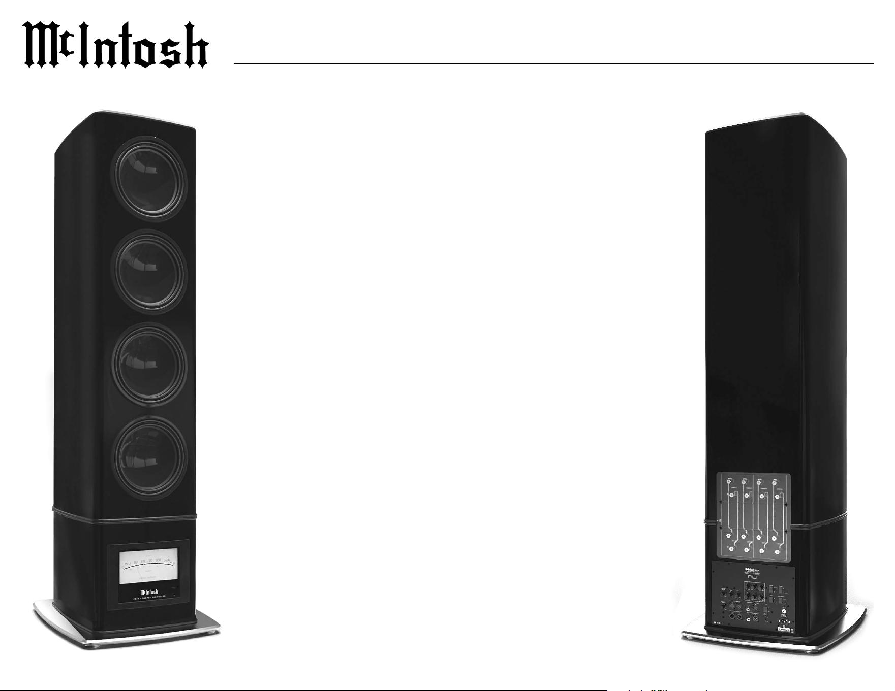
Introduction
The McIntosh PS2K Powered Subwoofer is designed
for Home Theater and Music Reproduction. It has
a four 13 inch LD/HP woofers, each powered by its
own 500 watt amplier, plus built-in High and Low
Pass Filters and two Parametric Equalizer Filters for
subwoofer room correction.
The PS2K Powered Subwoofer complements the
capabilities and the remarkably low distortion of
McIntosh Power Ampliers and loudspeaker systems.
Each component in the PS2K has been carefully
designed for durability, eciency, and above all, low
distortion. The McIntosh PS2K Powered Subwoofer
will reproduce music accurately and function as an
excellent Powered Subwoofer.
Safety First
Please read the safety instructions included in a
separate document called Important Additional
Operation Information Guide.
Safety Cover
The PS2K is factory equipped with a clear safety
cover on the rear surface. Do not remove this cover
for any reason, and never make any other electrical
connection to the terminals inside.

3
PS2K
Important Information
1. The following Connecting Cable is available from
the McIntosh Parts Department: Power Control
Cable Part No. 170202 Six foot, 2 conductor
shielded, with two 1/8 inch stereo mini phone plugs.
2. The PS2K’s Power Control Input will function
within a 5 to 20 DC Voltage range. The Power
Control Output will only send a signal if a source is
connected to the Power Control Input.
3. To avoid damage, do not connect the speaker level
output terminals from any receiver, amplier or
integrated amplier to the inputs of the PS2K
Powered Subwoofer.
4. The PS2K needs to be connected to a dedicated
circuit with AC outlet. The type and size of the
dedicated AC circuit with outlet needs to be in
accordance with the local electrical wiring codes.
Always contact your McIntosh dealer and certied
electrician for additional information and assistance.
Note: 20 Amp, 120 volt AC circuit for use in the United States and
Canada only.
Packing and Unpacking the PS2K
Warning: The PS2K is very heavy. Please refer to
Unpacking instructions located in a envelope
attached to the shipping crate. Be sure to have the
appropriate manpower available to handle safely.
The PS2K is nished in a highly polished but durable
paint. However, it can be scratched, so please ensure
all sharp objects like rings, belt buckles, watches,
etc are removed prior to handling. Also please note
the PS2K has no protective covers or grilles over the
woofers. So please ensure not to reach and grab the
product woofers.
Once removed and placed in your listening area, the
protective lm may be removed by slowly peeling
o, all around the speaker. Also remove the protec-
tive rubber ring on the metal base.
Pa
cking the PS2K is the reverse of unpacking, so
please be sure to save all instructions and materials.

4
Performance Features
• Woofers with Patented LD/HP
®
Technolog y
The McIntosh Low Frequency Loudspeaker
Elements feature the patented LD/HP Magnetic
Circuit Design. This design, when compared to
conventional Loudspeaker Drivers, reduces distor-
tion signicantly. It also increases power handling
an
d eciency.
The die cast basket has an open air area under the
voice coil/spider assembly to prevent displacement
noise. The carbon ber cone with a corrugated
rubber surround has a six layer high temperature
voice coil and is rigid to perform as a near perfect
air piston.
All together these advances in woofer design
construction and materials produce the very
important rst several octaves of music, with
a high degree of accuracy and superb transient
response. This performance level rivals woofers
twice the size of the PS2K woofer.
• Gold Plated Input Connectors
The PS2K Input Connectors are gold plated for
superior corrosion resistance and high electrical
conductivity.
• Low Harmonic and Intermodulation Distortion
The PS2K Loudspeaker System is capable of
reproducing the full dynamic range of a symphony
orchestra with very low audible distortion of any
kind.
• Sealed Enclosure
The PS2K uses acoustic suspension design
techniques. This type of loading was pioneered
decades ago, and uses a linear air spring of the
enclosure to keep distortion low, suspension under
control at all times, and provide an extended low
frequency output below resonance.
• Large Woofer with Integral Heat Sink
Massive dual magnets with thick front and back
plates provide an incredible heat sink for the
voice coil. The voice coil itself is wound on a 3”
diameter aluminum bobbin to further aid in the
dissipation of heat. The ability to dissipate heat
greatly improves the driver’s capacity to perform
at high power levels and not suer from power
compression.
• Rigid Woofer Framework
A black powder coated, die cast aluminum basket
is used as the framework for the driver. Such
framework is necessary to keep the driver’s
moving components aligned during the long
excursions a subwoofer can produce.
• Rigid Woofer Cone
The PS2K uses custom designed unied carbon
ber cone, dust cap, and coil mounting technology.
This provides exceptional cone rigidity to assure
no cone breakup under the most demanding
conditions. Additionally, the corrugated style cone
suspension provides extended linear cone travel
over most woofer designs.
• High Power and Low Distortion
The PS2K’s four 500 Watt Ampliers have very
low Total Harmonic Distortion (THD). This 0.05%
THD rating combined with the low distortion of
the McIntosh LD/HP Driver provides exceptionally
smooth and clean low frequency response.
• Power Guard
The patented McIntosh Power Guard circuit
prevents the PS2K’s Amplier from being over
driven into clipping, with its harsh distorted sound
that can also damage your valuable Loudspeaker.
• Signal Sensing Circuitry
In addition to the McIntosh Remote Power Control
feature, the PS2K utilizes signal-sensing circuitry.
This signal sensing circuitry is benecial when the
PS2K is to be located at a great distance from the
pre-amp and running an additional Power Control
Cable for remote turn-on is not feasible.
• Phase Control
The continuously variable phase control provides
precise adjustment for the subwoofer phase.
• Balanced and Unbalanced Inputs/Outputs
Balanced connections guard against induced noise
and allow long cable runs without compromising
sou nd quality.
• Sentry Monitor and Thermal Protection
McIntosh Sentry Monitor power output stage
protection circuits ensure the PS2K will have
a long and trouble free operating life. Built-in
Thermal Protection Circuits guard against
overheating.
• Parametric Filter
The Parametric Filter provides simple peak or dip
ltering to the subwoofer output for room eect
correction. These lters may be used to indepen-
dently from any other room correction methods.
• Signal Pass Through
Signal Pass through is used for easy chaining of
one PS2K to another.
5
PS2K
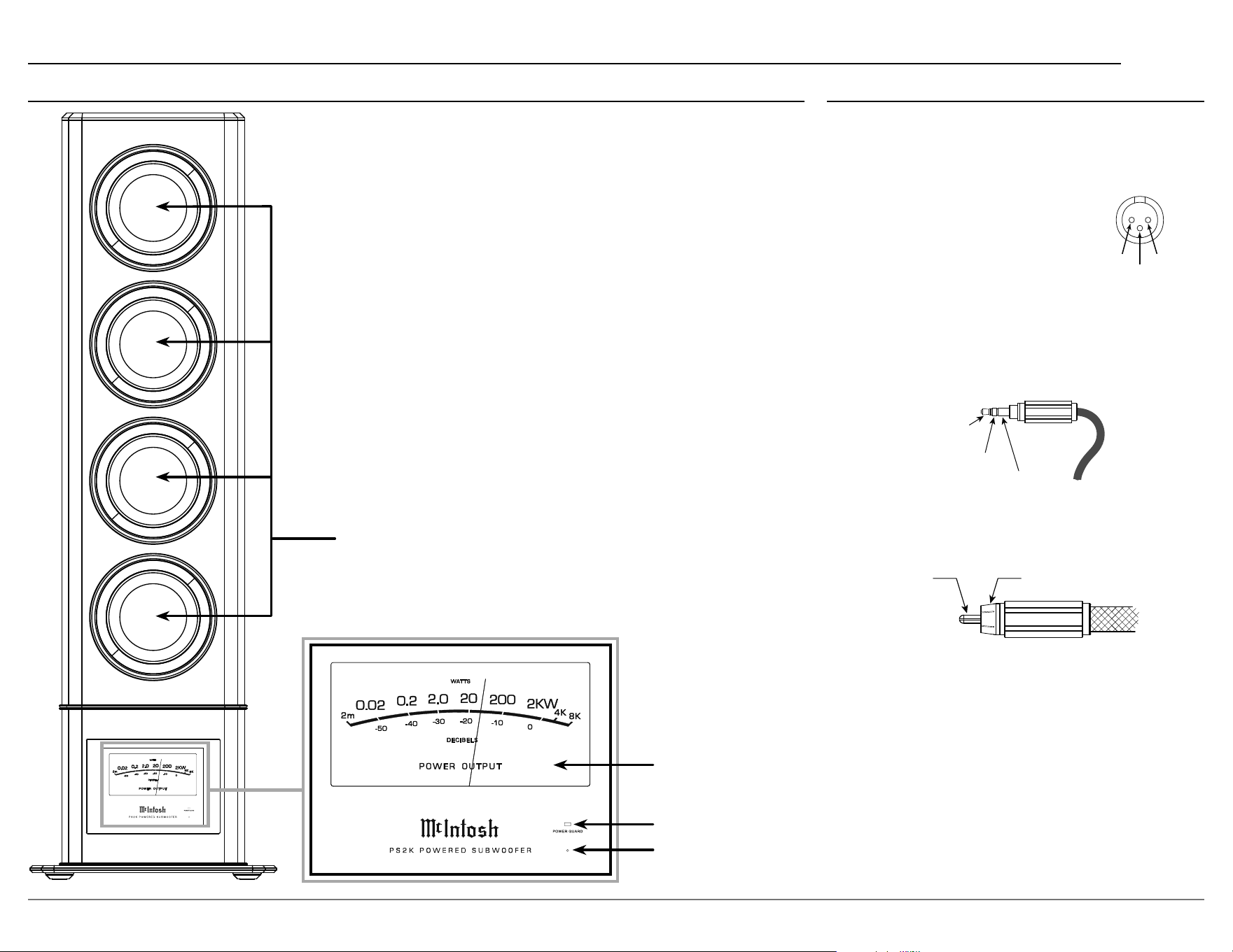
Four extra long excursion carbon
ber unied cone woofers
POWER OUTPUT Meter
POWER GUARD LED indicates amplier clipping
Standby LED
indicates that the PS2K is connected to power and ready to be
turned on via the rear panel switch or rear panel power control.
Front View Features
Connector Information
XLR Connectors
Below is the pin conguration for the XLR balanced
output connectors on the PS2K. Refer to the diagram
for connection:
PIN 1: Shield/Ground
PIN 2: + Input/Output
PIN 3: – Input/Output
Power Control Connectors
The PS2K POWER CONTROL INputs and
OUTputs on the rear panel send and receive power
on/o signals when connected to other McIntosh
components. A 3.5mm stereo mini plug is used for
the connections.
PIN 2
PIN 1
PIN 3
Meter
Illumination
Control
Power
Control
Ground
Signal Ground
Meter illumination can also be controlled via the
Power Control Input’s source.
RCA Connectors
6
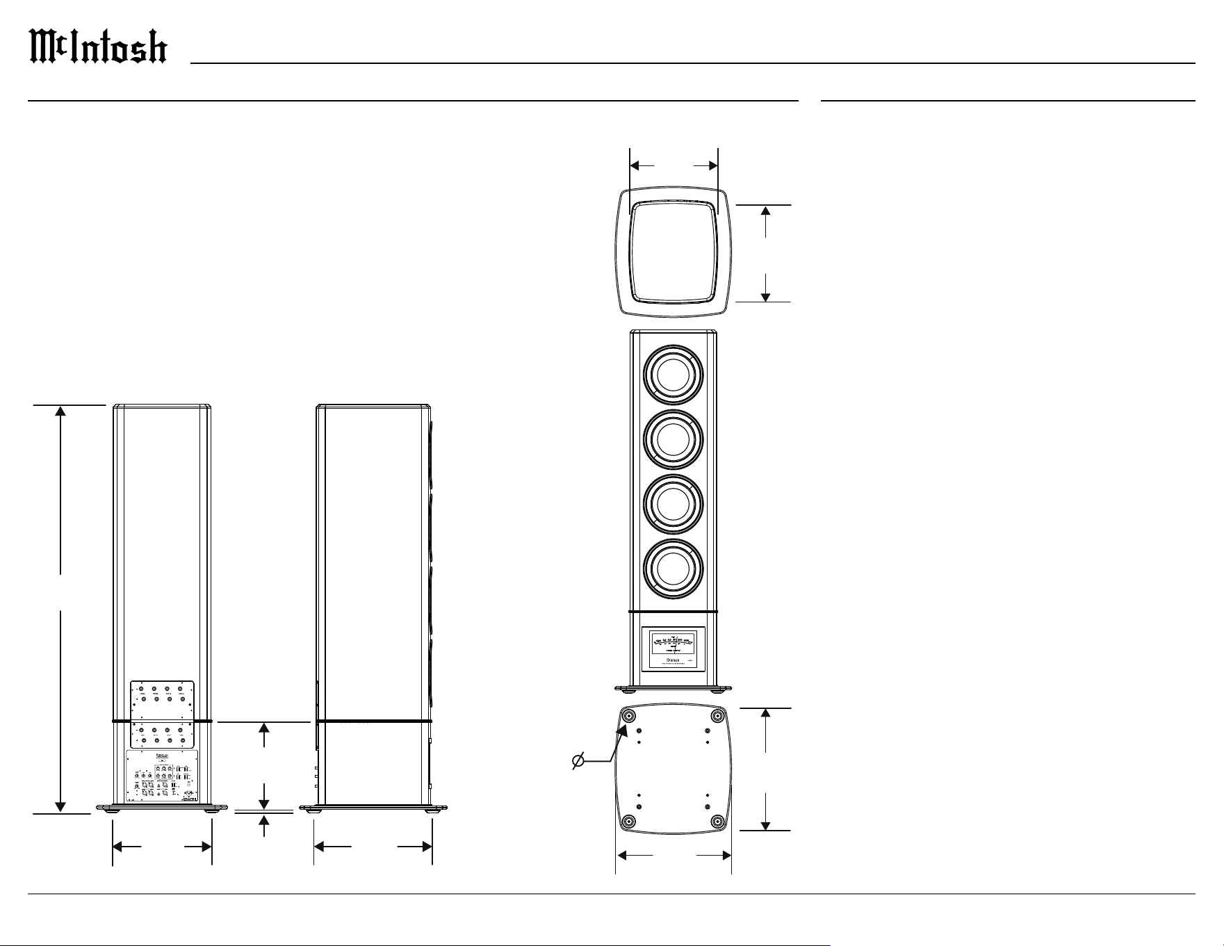
Dimensions
The following dimensions can assist in determining the best location for your PS2K Powered Subwoofer.
A Note on Placement:
It is important to keep your McIntosh unit out of direct sunlight and only use
appropriate gentle cleaners because the Organic Anodize can become discolored
over time.
While most products will maintain their classic dark features for their lifetime,
some situations can accelerate discoloration. The most pervasive culprit is UV
light, especially light directly from the sun, or high intensity spotlights. Even
high intensity short-term exposure can result in discoloration.
Chemicals can also alter the nish of the Anodize. Aggressive cleaners will take
their toll over time and actually etch away the Anodize nish.
Installation
Locating the PS2K
The optimal method for selecting speaker locations
includes the use of a real time spectrum analyzer
(RTA) operated by an experienced system installer.
An uncompromising installation would take into
consideration the oor, wall and ceiling coverings,
the type and placement of furniture and can even
include the architectural design of the room and its
construction materials. Frequencies 80Hz and below
reproduced by the PS2K Powered Subwoofer are
non-directional and will sound best located toward
the front of the room and away from corners. It is not
necessary to aim the front of the PS2K directly at the
listener.
78 5/8”
199.7 cm
19 1/4”
48.9 cm
22 7/8”
58.1 cm
22”
55.9 cm
28 7/16”
72.2 cm
18 3/4”
47.6 cm
25 1/4”
64.1 cm
5/8”
1.6 cm
17”
43.2 cm
2 15/16”
7.5 cm
78 5/8”
199.7 cm
19 1/4”
48.9 cm
22 7/8”
58.1 cm
22”
55.9 cm
28 7/16”
72.2 cm
18 3/4”
47.6 cm
25 1/4”
64.1 cm
5/8”
1.6 cm
17”
43.2 cm
2 15/16”
7.5 cm
7
PS2K
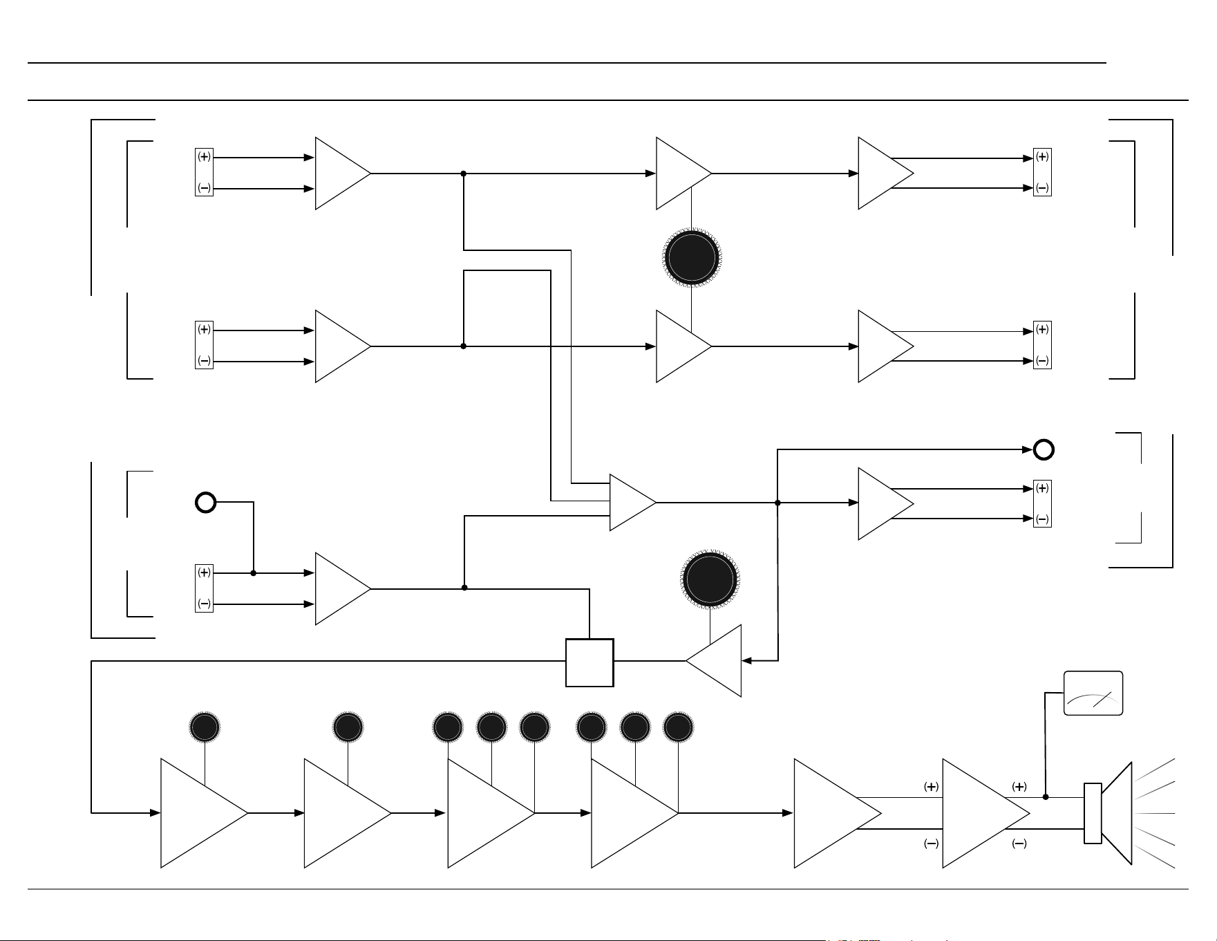
Signal Flow Block Diagram
Signal Flow Block Diagram
LVL
BWFq LVL
PHASE
LEVEL
LEVEL
ADJ
ADJ
POWER
POWER
AMP
AMP
LEFT
BAL
SUB
UNBAL
SUB
BAL
BAL TO UNBAL
PREAMP OUTPUTS
HPF
BAL DRIVER
HPF
LPF
SUB OR LFE
SUB OR LFE
L+ R
SUB/LFE OUT
LPF
LPF
30-100Hz
30-100Hz
PEQ2
PEQ2
BWFq LVL
BAL TO UNBAL
BAL TO UNBAL
SUM
30-100Hz
30-100Hz
PEQ1
PEQ1
AMP
DIFFERENTIAL
DRIVER
METER
RIGHT
BAL
2ND ORDER
40-100Hz
MONO
BAL DRIVER
BAL DRIVER
4TH ORDER
40-100Hz
LFE/
SUB
SWITCH
MONO
PREAMP INPUTS
STEREO
STEREO
PHASE ADJ
0-180°
HPF
RIGHT
BAL
HPF
LEFT
BAL
SUB
BAL
SUB
UNBAL
LFE
SUB
SUB

8
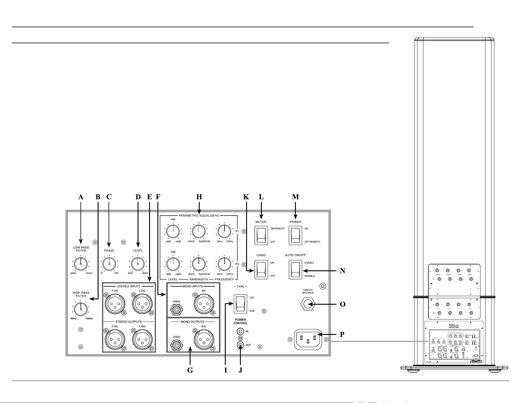
Rear Panel
A. LOW PASS FILTER
allows for an adjustable
cut-o frequency between 40Hz and 100Hz to the
subwoofer
. This setting is typically set to match the
HIGH PASS FILTER setting below.
The LOW PASS FILTER is always used if
c
o
nnected to Left and Right Inputs. To apply the
LOW PASS FILTER the TYPE Switch must be set
to SUB.
B. HIGH PASS FILTER allows for an adjustable
cut-o frequency between 40Hz and 100Hz from
the normal left and right loudspeakers. This lowers
distortion, prevents overloading the left and right
loudspeakers, and provides optimal blending with
the Subwoofer output.
To use the HIGH PASS FILTER, connect the L and
R ou
tput of a pre-amplier or integrated ampli-
er to the left and right inputs of the PS2K and
c
o
nnect the L and R outputs of the PS2K to your
power amplier(s) and set the crossover frequency
depending on the size and or specications of your
loudspeakers. Suggested settings would be 40 Hz
for very large loudspeakers like a XRT 2.1K or
XRT 1.1K, 60 Hz for medium size loudspeakers
such as a XR100, or 80 Hz for smaller speakers
such as XR50.
If setting the PS2K for Home Theater use, the AVR
w
i
ll typically have these settings internal. If this
is the case, then no L or R connection or setting is
required on the PS2K.
C. PHASE Knob sets the acoustic output phase
to provide optimum blending into your system
relative to its input. This knob is to help avoid
phase cancellation (characterized by a loss of bass
information) between the PS2K and any other low
frequency producing speaker in the system. Careful
listening while turning the PHASE knob will help
you determine if this eect will be benecial to the
system.
D. LEVEL Knob sets the gain / balance of the
subwoofer’s output to match the rest of the system.
Start with the LEVEL Knob in the center position
an
d perform the system level calibration on the
A/V Control Center or Surround Decoder for the
subwoofer level. If the subwoofer level can not be
set, adjust the PS2K’s LEVEL Knob to provide
adequate range during calibration.
E. STEREO INPUTS and OUTPUTS
Stereo Inputs are used in a two channel music
sy
stem, or any system where a pre-amplier
or AVR is not applying LOW or HIGH PASS
FILTERs to any loudspeaker output channel. In
this case, connect the pre-amplier or AVR Left
and Right outputs to the PS2K Left and Right
Inputs.
Stereo outputs are used to connect to Left and
Ri
ght amplier inputs of an Integrated amplier,
AVR, or Left and Right loudspeaker amplier after
the HIGH PASS FILTER is applied. Never connect
the speaker level outputs of an AVR or 2 channel
integrated amplier to the Stereo inputs of the
PS2K.
F. MONO INPUTS
If connected to the output of another PS2K or other
s
u
bwoofer, then select SUB on the TYPE Switch.
If connected to the LFE output of a pre-amplier
o
r A
VR that has the ability to apply a custom lter
setting, then select LFE on the TYPE Switch.
G. MONO OUTPUTS connect to the input of another
PS2K or other subwoofers in a system. When the
TYPE Switch is set to SUB the output will be the
sum of both the stereo and mono inputs and the
internal LP lter of the PS2K is applied.
If connected to the subwoofer output of an
i
n
tegrated amplier then select SUB on the TYPE
Switch.
H. PARAMETRIC EQUALIZERS provide adjust
-
ments for room eect compensation. The lters are
a
p
plied only to the subwoofer output. The available
lter adjustments are Frequency, Bandwidth, and
Level.
The best way to set the parametric lters is with
t
h
e use of a spectrum analyzer and a noise source.
This will allow pinpoint accuracy of the settings.
However, if unable to use such a sophisticated
instrument, one may play typical music and listen
for boominess or lack of output in music or other
signal material.
Troubleshooting the Parametric Filter
If there is a lack of output, set P1 lter’s level to
+d
B position.
If a boomy sound is heard, set P1 lter’s level to
-
d
B position.
Set bandwidth to center position. Now play the
s
i
gnal material and adjust the frequency control
until a correction is heard. Adjust the frequency
knob until it is centered on the eect. Next, adjust
the level control until the sound is more uniform.
Further adjustment of the bandwidth control
localizes the correction to only that band where the
action is desired.
The P2 lter may be adjusted in a similar manner if
th
e sound output is boomy or lacking character.
Note: 1. Each filter is fully independent of the other, so one
may be adding and the other subtracting from the
nominal output of the PS2K, or both adding or both
subtracting.
2. Both Parametric filters can be bypassed by placing
their LEVEL control to 0dB.
I. Input TYPE Switch
If receiving audio with lters already applied to its
si
gnal, set switch to LFE.
If receiving unltered audio, set type to SUB.
9
PS2K
J. POWER CONTROL IN and OUT
Connect a Power Control Cable to the INput from a
Co
ntrol Center or Preamplier to automatically turn on
the PS2K when the Control Center or Preamplier is on.
Connect a Power Control Cable to the OUTput to send
th
e signal to additional subwoofers or other McIntosh
components to automatically turn them on as well. For
the OUTput to function, a source must be connected to
the Power Control INput
K. LOGO Switch controls the Logo lighting for home
theater purposes.
L. METER Switch controls the PS2K’s Meter Lighting
On/O. When in the ON position, the PS2K will also
accept power control signals to control the Meter
lighting.
M. POWER Switch
When set to the OFF position, the PS2K can only be turned
on b
y a Remote Power Control signal. When set to the ON
position, the PS2K will stay on depending on the position of
the AUTO ON/OFF switch. Using an active Power Control
signal will disable this circuitry.
N. AUTO ON/OFF Switch
When set to ENABLE, the PS2K will time out with the
a
b
sence of audio after 30 minutes. If Audio is detected, the
PS2K will trigger back ON. Using an active Power Control
signal will disable this circuitry.
O. CIRCUIT BREAKER should never activate under normal
conditions. If the breaker does activate, the tip of the breaker
will pop out. Reset the breaker by pushing in on the tip.
P. AC Input is used to connect the PS2K to an AC outlet.
Rear Panel (continued)
10
6
8
MIC
SERIAL
NUMBER
LF
A
B
RF
LS RS
C
LFE
LRS RRS
IR IN
1
2
3
4
1
2
3
4
PHONO
GND
DATA OUT
AUX 1
AUX 2
AUX 3 AUX 4
USB 3
PC AUDIO IN
7
DIGITAL INPUTS
L R
L R
AUDIO INPUTS
BAL IN 1
BAL IN 2
MULTI CHANNEL IN
A
B
POWER CTRL OUT
1
2
1
2
3
4
L
R
ZONE B OUT
L
R
LF
C
LS
LRS
RF
SUB
RS
RRS
5
RS232
NET 1 LAN
PRO CES SOR
SD CARD
1
USB
2
LTF
RTF
LTR
RTR
BALANCED OUTPUTS
L
R
ZONE
OUT
CAUTION
ATTENTION: RISQUE DE CHOC ELECTRIQUE-NE PAS OUVRIR
RISK OF ELECTR IC SHOCK
DO NOT OPEN
1
2
3
4
5
1 2
HDMI INPUTS
HDMI OUTPUTS
A/V PROCESSOR
McINTOSH L ABORATORY, INC., BINGHAMTON, NY
HANDCRAFTED IN USA WITH US AND IMPORTED PARTS
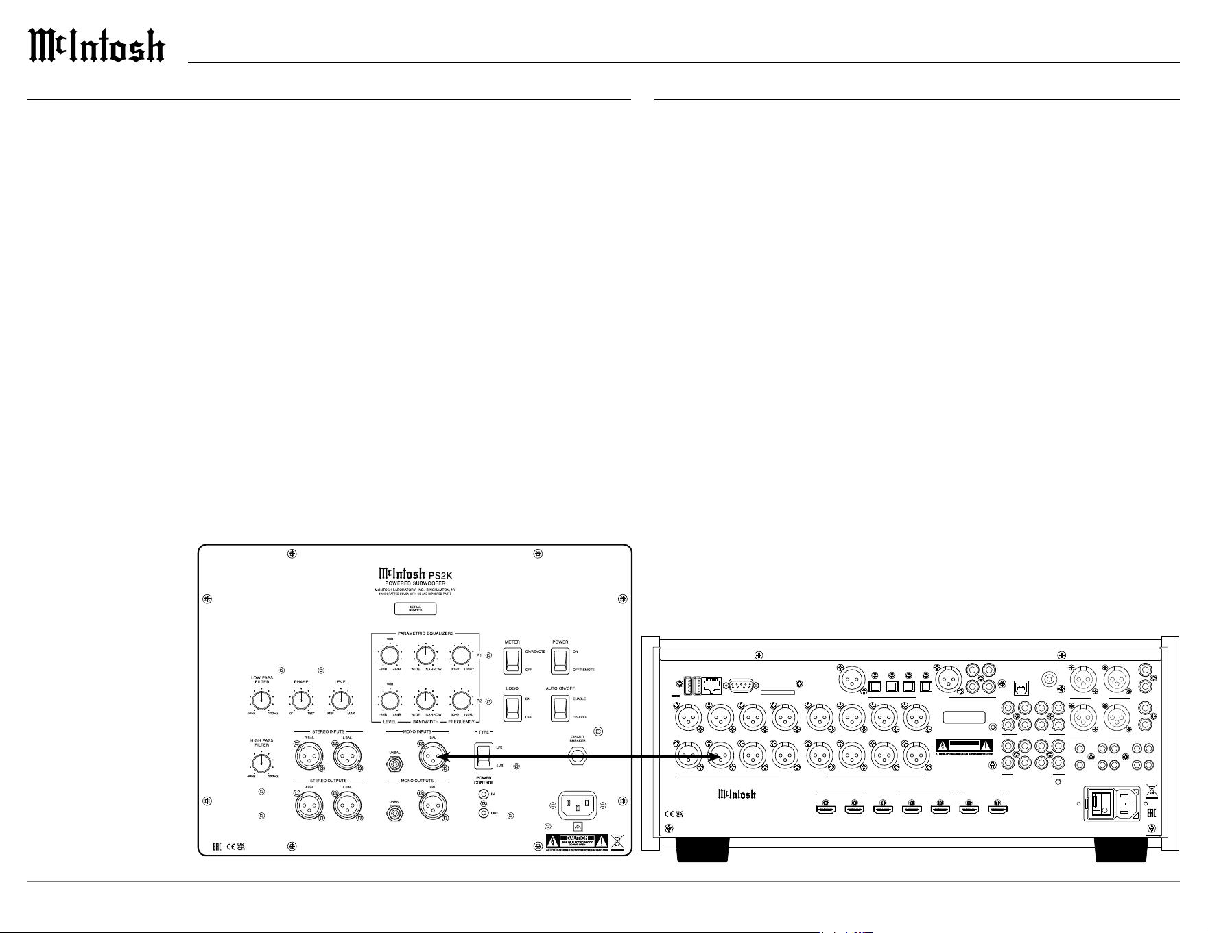
Connection Diagram: Subwoofer/LFE Outputs
Home Theater Connection
Typical AVRs or AV processors will apply custom subwoofer lter settings.
Connect an AVR, Subwoofer, or LFE output to the mono subwoofer input of
the PS2K. The TYPE Switch should be set to LFE.
Home Music System Connection
Connection to a pre-amplier or music processor / integrated amplier is
made from the subwoofer output to the mono subwoofer input of the PS2K.
• If the pre-amplier or music processor has an available adjustable
crossover setting, use it and set the TYPE Switch to LFE. If the
pre-amplier or music processor does not have a adjustable setting, set
the TYPE Switch to SUB.
How to Connect
The McIntosh PS2K Powered Subwoofer may be turned On or O by two dierent
methods. The preferred method is to utilize the Power Control Signal from a McIntosh
A/V Control Center or Audio Control Center. If the Power Control Signal is not avail-
able, the PS2K has built-in signal-sensing circuitry which will automatically turn-on
th
e Powered Subwoofer.
1. Connect a power control cable from the McIntosh A/V Control Center or Audio
Control Center Power Control Out Jack to the McIntosh PS2K POWER CONTROL
IN Jack.
2. Connect a power control cable from the McIntosh PS2K POWER CONTROL OUT
Jack to the McIntosh Power Amplier Control In Jack.
Notes: • If two or more McIntosh PS2K Powered Subwoofers are being used in the same system, connect the
POWER CONTROL OUT from the first PS2K to the next PS2K POWER CONTROL IN Jack and
then onto the McIntosh Power Amplifier.
• The PS2K’s Power Control Input will function with 5 to 20 Volts DC applied.
• The PS2K Power Control output requires connection of a switched Power Control input to function.
3. Connect a Balanced Audio Cable from the McIntosh A/V Control Center or Audio
Control Center Subwoofer Out to the McIntosh PS2K MONO INPUT(S).
Notes: If two or more McIntosh PS2K Powered Subwoofers are being used in the same system, connect a
second Audio Cable from the first PS2K MONO OUTPUT(S) to the next PS2K MONO INPUT(S).
4. Connect the PS2K power cord to an active AC outlet.
11
PS2K
6
8
MIC
SERIAL
NUMBER
LF
A
B
RF
LS RS
C
LFE
LRS RRS
IR IN
1
2
3
4
1
2
3
4
PHONO
GND
DATA OUT
AUX 1
AUX 2
AUX 3 AUX 4
USB 3
PC AUDIO IN
7
DIGITAL INPUTS
L R
L R
AUDIO INPUTS
BAL IN 1
BAL IN 2
MULTI CHANNEL IN
A
B
POWER CTRL OUT
1
2
1
2
3
4
L
R
ZONE B OUT
L
R
LF
C
LS
LRS
RF
SUB
RS
RRS
5
RS232
NET 1 LAN
PRO CESS OR
SD CARD
1
USB
2
LTF
RTF
LTR
RTR
BALANCED OUTPUTS
L
R
ZONE
OUT
CAUTION
ATTENTION: RISQUE DE CHOC ELECTRIQUE-NE PAS OUVRIR
RISK OF ELECTRI C SHOCK
DO NOT OPEN
1
2
3
4
5
1 2
HDMI INPUTS
HDMI OUTPUTS
A/V P ROCESSOR
McINTOSH LA BORATORY, INC., BINGHAMTON, NY
HANDCRAFTED IN USA WITH US AND IMPORTED PARTS
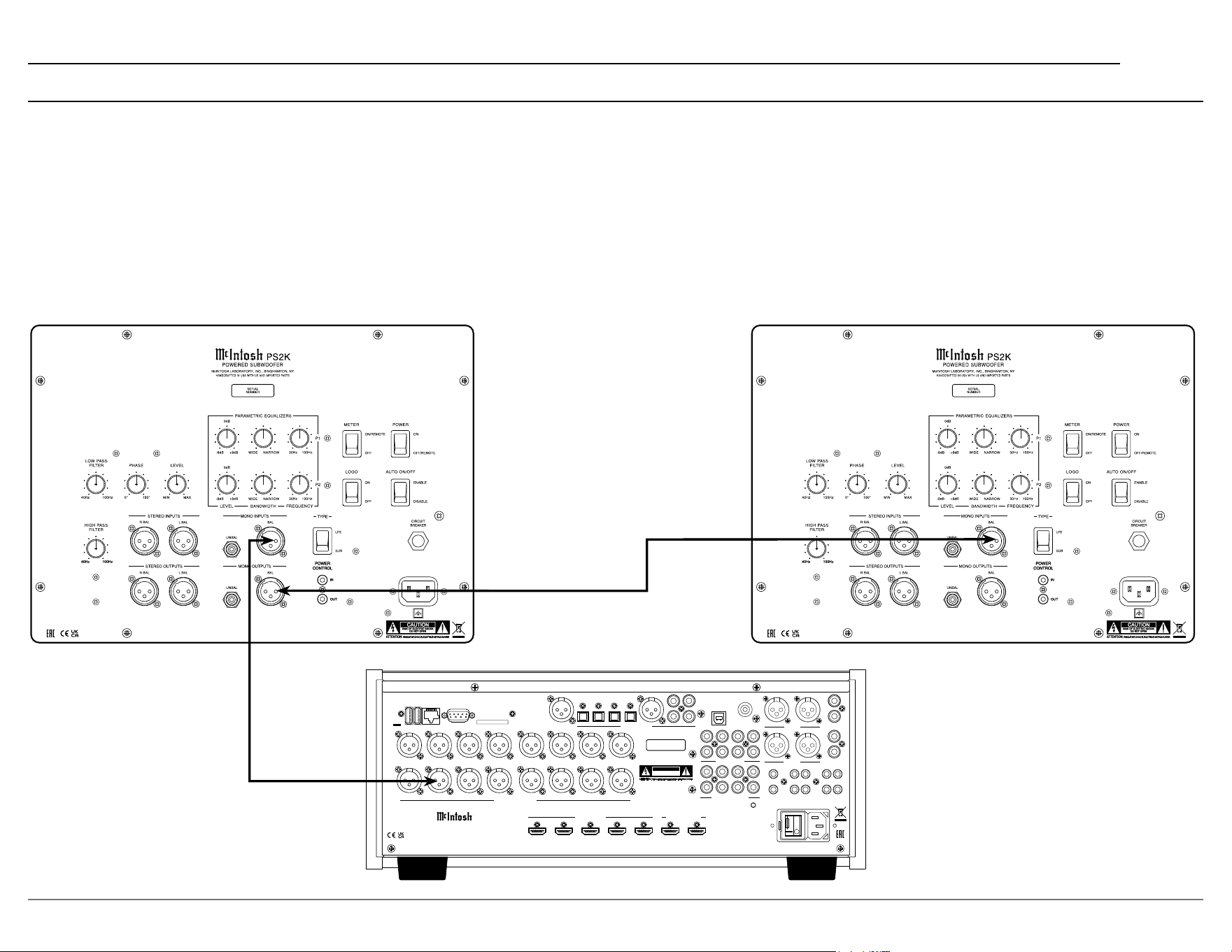
Connection Diagram: Chain
To connect multiple PS2Ks to an A/V Processor in a single system use the following connections:
• The TYPE Switch should be set to SUB, this allows for signal path to go through the system’s LOW PASS FILTER.
• The LOW PASS FILTER should be set to the L and R loudspeaker’s rated low frequency point. This is typically 40 Hz for large loudspeakers, 60 Hz for medium
size loudspeakers, and 80-100 Hz for small loudspeakers.
• The HIGH PASS FILTER should be set to match the LP lter setting used above.
12
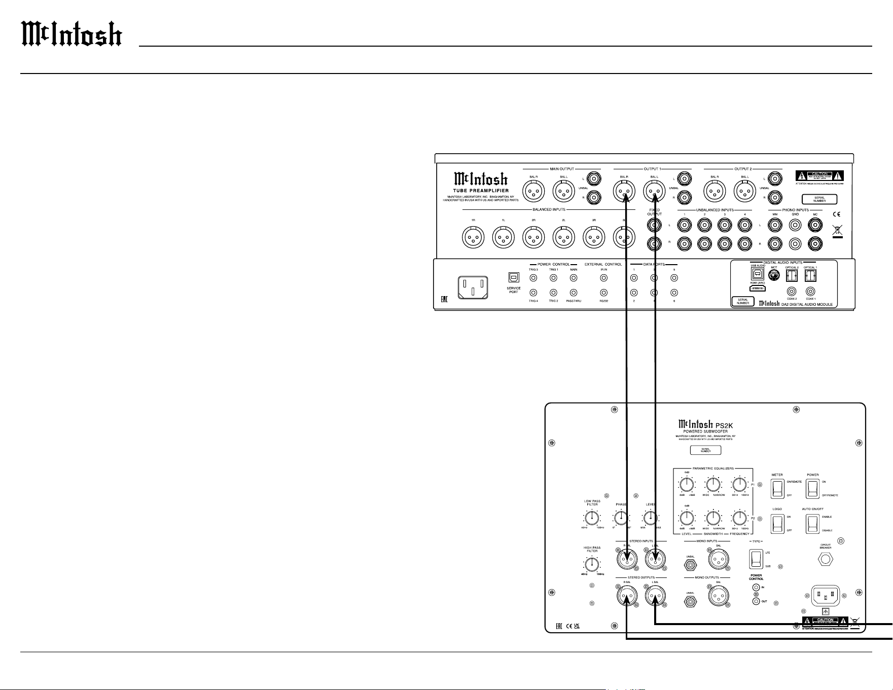
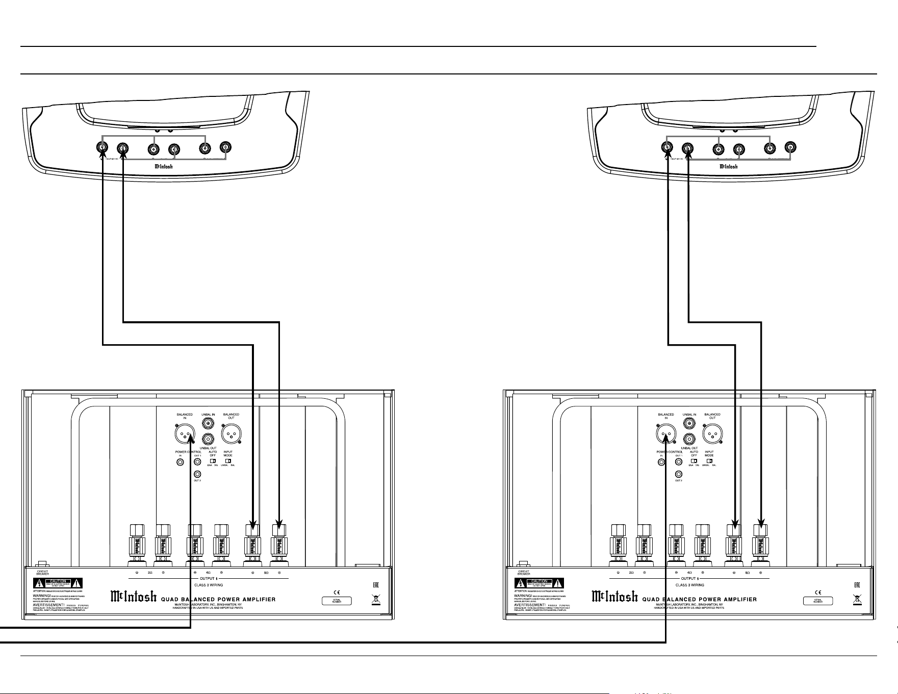
Connection Diagram: Two Channels
Home Music System Connection
Connection to a pre-amplier or music processor / integrated amplier
without a dedicated subwoofer output is made from the Left and Right
line level outputs to the Left and Right inputs of the PS2K. Using this
method allows ltering of low frequencies from the normal Left and
Right loudspeakers in your system, thus relieving them of the low
frequency burden and reducing their distortion and optimally blending the
output of the subwoofer and loudspeakers.
• The LOW PASS FILTER should be set to the L and R loudspeaker’s
rated low frequency point. This is typically 40 Hz for large loudspeak-
ers, 60 Hz for medium size loudspeakers, and 80-100 Hz for small
lo
udspeakers.
• The HIGH PASS FILTER should be set to match the LP lter setting
used above.
Note: More than one PS2K may be chained in a music system setup. In this case, follow the
chain from the first PS2K to the second as described previously and set the TYPE
to SUB. Set the LP filter to match the lead PS2K and adjust parametric filters as
necessary for smooth performance.
13
PS2K
Power
Control
IN
OUT
Power
Control
IN
OUT
Left Speaker Right Speaker
Left Channel Amplier
Right Channel Amplier
Connection Diagram: Two Channels (continued)

14
Specications
System Driver Complement
Four 13 inch extra long excursion Carbon Fiber
Woofers (incorporating LD/HP)
Impedance
8 ohms Nominal
Power Output
Amplier: 2 KW (Four 500W, one per woofer)
Maximum Output > 120 dB
Filter Frequencies
High Pass: 40 Hz - 100 Hz
Low Pass: 40 Hz - 100 Hz
Phase: Continuously Variable
Parametric: Two band 30 Hz - 100 Hz, variable band
-
width and level +/- 8 dB
Input sensitivity (Rated Output)
500mV unbalanced (0.5V)
1V Balanced
THD
Amplier: 0.05%
Preamplier (Rear Panel Outputs): 0.005%
Voltage Gain
Amplier: 31dB
Preamplier: 10dB
Signal to Noise ratio (A-weighted)
Amp: 115dB
Preamp: 100dB
Input Impedance
20,000 Ohms Balanced
10,000 Ohms Unbalanced
Maximum Input Signal
4.5V Unbalanced
9V Balanced
Power Control In
5-20 VDC Trigger
Power Requirements
120 Volts, 50/60Hz at 6.0 amps
240 Volts, 50/60Hz at 3.0 amps
General Specications
Note: the PS2K has been tested and certified for indoor use only.
Enclosure Finish
Highly polished Piano Grade Black
Metal Finish
Anodized Aluminum Base, High Durable Powder
Coated Plate Surfaces
Overall Dimensions
Width is 19 1/4 inches (48.9cm)
Height is 22 1/2 inches (57.2cm)
Depth is 78 5/8 inches (199.7cm)
The base is 25 5/16 inches by 28 7/16 inches
Weight
458 pounds (207.7 kg) net
932 pounds (422.7 kg) in shipping carton
Shipping Carton Dimensions
Width is 36 inches (91.4cm)
Depth is 54 inches (137.2cm)
Height is 89 inches (226.1cm)
Trademarks of McIntosh Laboratory, Inc.:
The following are Registered Trademarks of McIntosh Laboratory, Inc. in multiple jurisdictions around the world: the written McIntosh logo; the McIntosh Globe logo; the Mc logo; Power Guard; Power Guard
Screen Grid Sensor; Power Guard SGS; LD/HP; Dynamic Power Manager; the 4DPM8 logo; HXD; the HXD logo; Behind The Sound; Legendary Performance.
The following are Trademarks of McIntosh Laboratory, Inc. in multiple jurisdictions around the world: Autoformer; Sentry Monitor; Solid Cinch; McIntosh Monogrammed Heatsinks; Hybrid Drive; DualView;
TripleView; Made of Sound.
The foregoing trademarks, registered and otherwise, are not to be used, reproduced, or registered in any way without the express written permission of McIntosh Laboratory, Inc.
15
PS2K
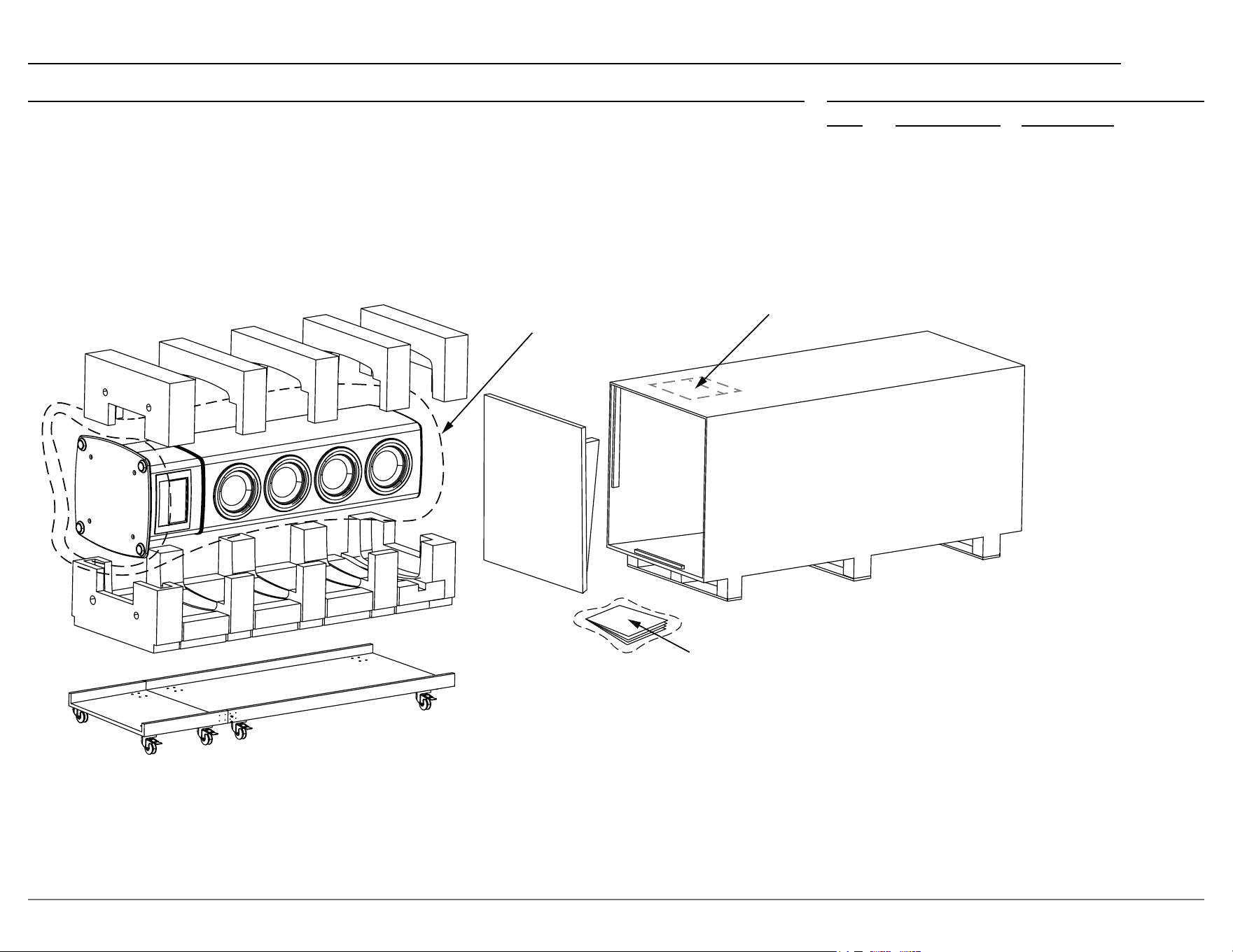
Packing Instructions Part List
Qty Part Number Description
1 034735 Packing List Envelope
1 034720 Protective Bag
1 752871 Manual Pack
1 241286 Unpack Instructions
In the event it is necessary to repack the equipment
for shipment, the equipment must be packed exactly
as shown in the unpack instructions.
Use the original shipping carton and interior parts
only if they are all in good serviceable condition.
If a shipping carton or any of the interior part(s)
are needed, please call or write Customer Service
Department of McIntosh Laboratory. Refer to page 2.
Please see the Part List for the correct part numbers.
PROTECTIVE BAG (BLUE)
UNPACK INSTRUCTIONS
MANUAL PACK
03473500 Packing List Envelope (1)
03472000 Protective Bag (Blue) (1)
75287100 Manual Pack (1)
24128600 Unpack Instructions (1)

The continuous improvement of its products is the
policy of McIntosh Laboratory, Inc. who reserve
the right to improve design without notice.
Printed in the U.S.A.
McIntosh Laboratory, Inc.
2 Chambers Street
Binghamton, NY 13903
www.mcintoshlabs.com
© 2024 McIntosh Laboratory, Inc.
McIntosh Part No. 24122100