
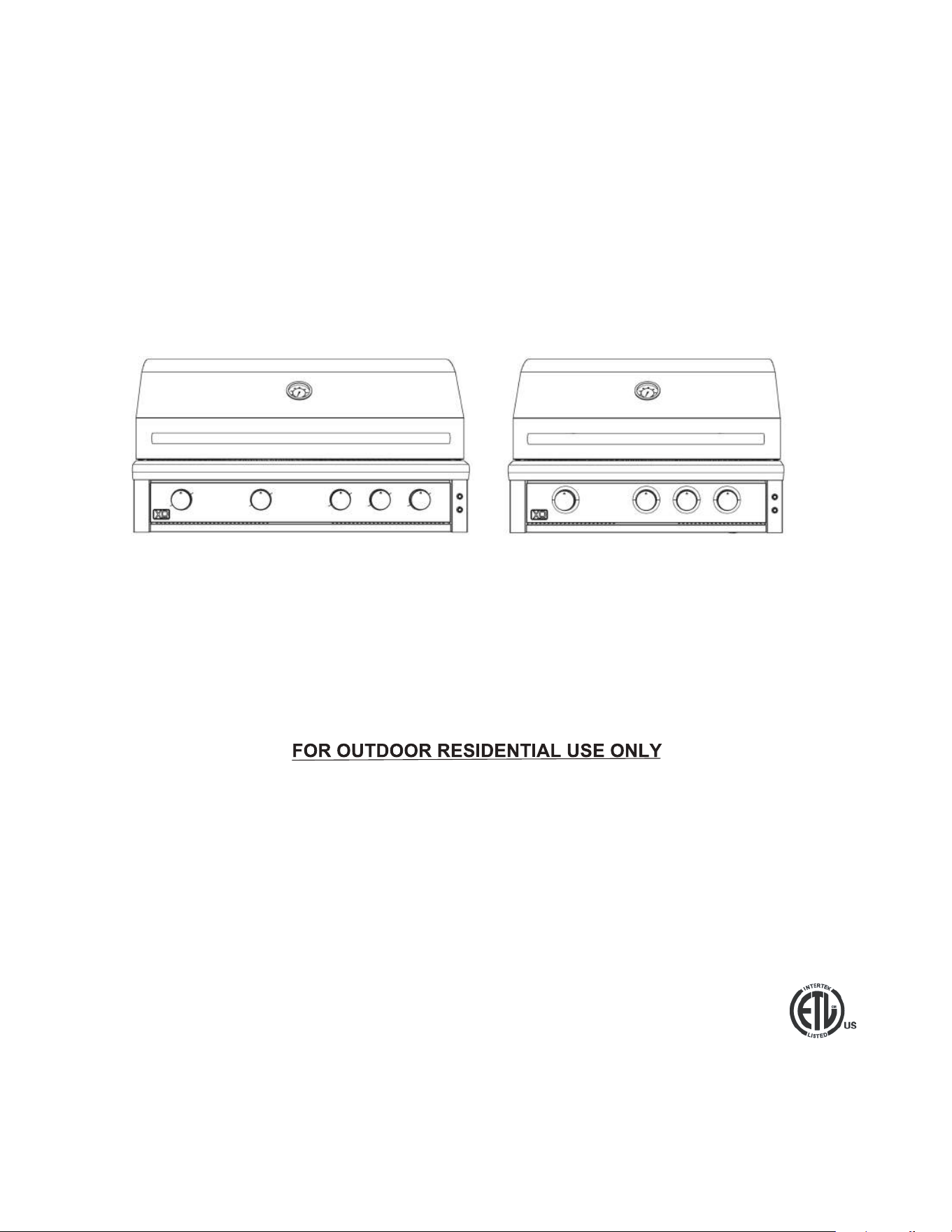
XO PERFORMANCE XLT GAS GRILL
MODELS: XOGRILL32XLT2 | XOGRILL40XLT2

14
A P P LIANC E
When buying any XO appliance
you can be confident you have chosen a
high quality, innovative and stylish product
from a company that cares about you!
If you require service or have questions,
Help is only a phone call away -
call: 973-403-8900
Talk to one of our appliance experts.
www.xoappliance.com/register-your-product/
CONGRATULATIONS
on purchasing your XO.
Before you proceed, take just a
moment to register your XO at:
REGISTRATION HELPS YOU BY -
Ensuring warranty coverage should you need service
Providing ownership veri
cation for insurance purposes
XO can notify you in the event of product changes or recalls.
Or simply scan here to be taken
to the registration page...
2
You may require service or parts one day -
take a minute to locate and record some important info about your grill.
• Model number
• Date of purchase
• Proof of purchase by the original owner
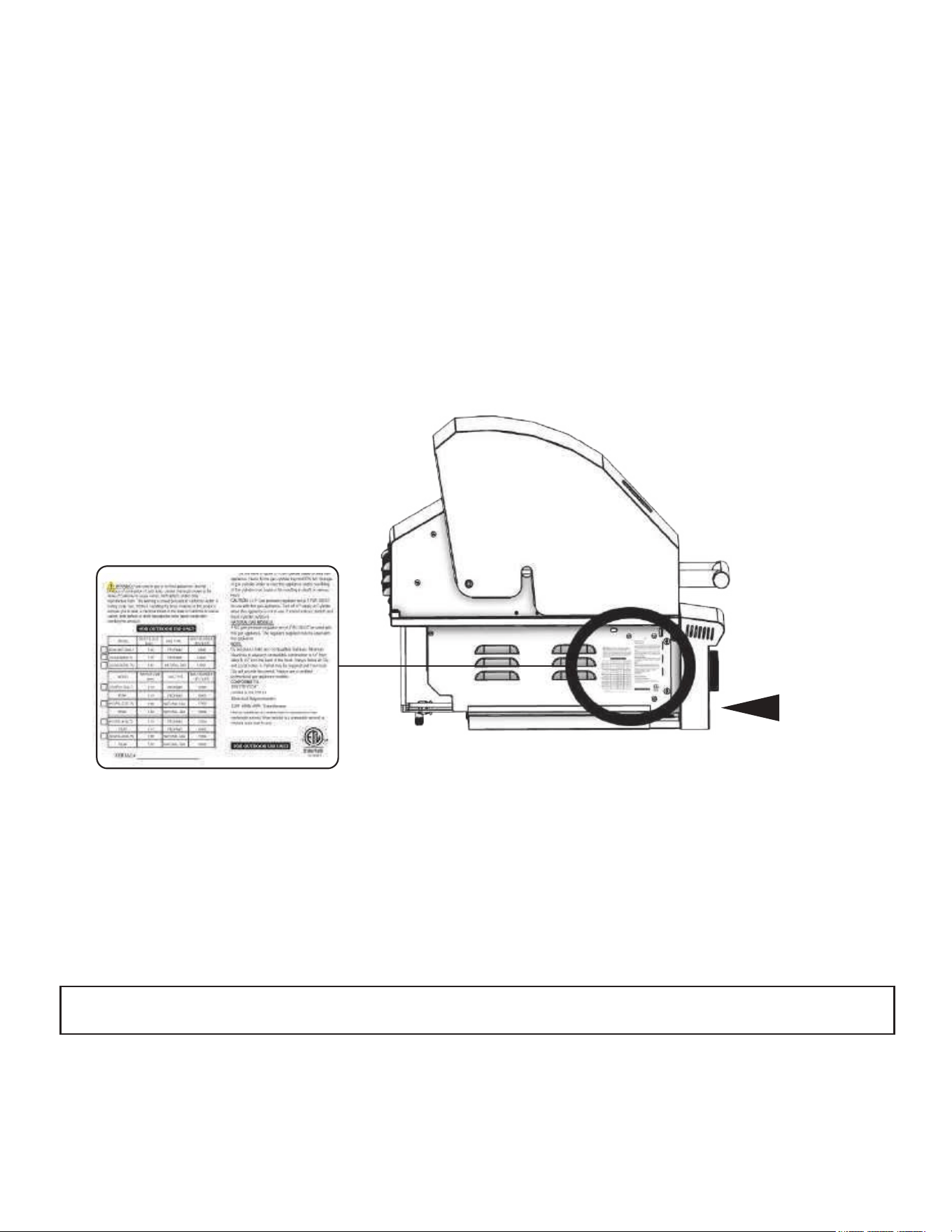
• Serial number
The serial number can be located on the rating plate which is located on the left side of the grill or on the pull-
out drip tray lighting instructions and also on the underside of the drip tray.
TAKE A MINUTE TO CIRCLE YOUR MODEL NUMBER ABOVE
AND RECORD YOUR SERIAL NUMBER HERE:
XOGRILL40XLT2 XOGRILL40XLT2
MODEL AND SERIAL NUMBER
DRIP TRAY
RATING PLATE
3
Read this manual carefully and completely before installing, servicing or operating the grill to reduce risk of:
1. FIRE
2. PERSONAL INJURY OR PROPERTY DAMAGE
3. IMPROPER INSTALLATION
THIS PRODUCT IS FOR OUTDOOR USE ONLY. Do not install or operate indoors, including but not limited
to garages, screened in porches, breezeways, gazebos or other enclosed areas. This outdoor cooking
appliance is not intended for installation in or on recreational vehicles, boats, trailers, or other such moving
vehicles. It cannot be installed in any area with limited or no ventilation. Failure to operate this unit in a well-
ventilated space can cause property damage, injury, or death. Keep the area surrounding the grill clear and
free from all combustible materials, gasoline and other flammable vapors and liquids.
IMPORTANT - WARNINGS
DANGER
WARNING
1. The outdoor gas cooking appliance and its individual shutoff valve must be disconnected from the gas supply
piping system during any system pressure testing in excess of 0.5 psi (3.5 kPa).
2. The outdoor gas cooking appliance must be isolated from the gas supply by closing its individual shutoff valve
piping system during any system pressure testing in less than or equal to 0.5 psi (3.5 kPa).
IF YOU SMELL GAS:
1. SHUTOFF THE GAS TO THE APPLIANCE.
2. EXTINGUISH ANY OPEN FLAME | SECURE ANY POTENTIAL IGNITION SOURCES
3. OPEN THE HOOD AND DOORS TO THE CART OR ISLAND
If odor continues, keep away from the appliance - IMMEDIATELY call your gas provider and/or your local fire
department
CAUTION
DANGER
DO NOT store gasoline or other flammable liquids or vapors within 25’ of this or any gas appliance.
Do not store or install additional propane tanks within 10’ of this or any other gas appliance.
The installation must conform with all local code or, in the absence of local codes, with either the National
Fuel Gas code ANSIZ223.1/NFPA 54 or the National Gas and Propane Installations code, CSA B149.1, or
the Propane Storage and Handling code, CSA B149.2.
4
1. Massachusetts requires all gas be installed using a plumber or gas fitter carrying the appropriate
Massachusetts license.
2. All permanently-installed natural gas or propane installations require a “T” handle type manual gas valve
be installed in the gas supply line to this appliance.
3. This does not apply to portable propane installations using a 20 pound cylinder.
IMPORTANT
NOTICE: COMMONWEALTH OF MASSACHUSETTS
WARNING: CALIFORNIA PROPOSITION 65
Never leave children unsupervised around the XO grill.
Pre-heating for more than 15 minutes may overheat and cause damage to the grill.
Never cover slots, holes, or passages in the grill fire box or cover an entire rack with material such as aluminum
foil. Doing so blocks air flow through the oven and may cause carbon monoxide poisoning. Aluminum foil linings
may trap heat causing a fire hazard.
Do not leave the grill unattended
.
CAUTION
The burning of gas cooking fuel generates some by-products which are on the list of substances which are
known by the State of California to cause cancer or reproductive harm.
California law requires businesses to warn customers of potential exposure to such substances. To minimize
exposure to the substances, always operate this unit according to the use and care instructions found in this
manual. Be certain to provide adequate ventilation when cooking.
Warning: Handling the brass material on this product exposes you to lead, a chemical known to the state of
California to cause cancer, birth defects or other reproductive harm. (Wash hands after handling this product.)
5
For more information go to this website
www.P65warnings.ca.gov
THIS INSTRUCTION MANUAL CONTAINS IMPORTANT INFORMATION NECESSARY FOR THE PROPER
ASSEMBLY AND SAFE USE OF THE APPLIANCE. READ AND FOLLOW ALL INSTRUCTIONS AND
WARNINGS BEFORE ASSEMBLING AND USING THE APPLIANCE. FOLLOW ALL WARNINGS AND
INSTRUCTIONS WHEN USING THE APPLIANCE. FAILURE TO INSTALL AND OPERATE THIS UNIT
IN ACCORDANCE WITH THESE INSTRUCTIONS CAN CAUSE PROPERTY DAMAGE, INJURY OR DEATH.
THANK YOU FOR CHOOSING XO
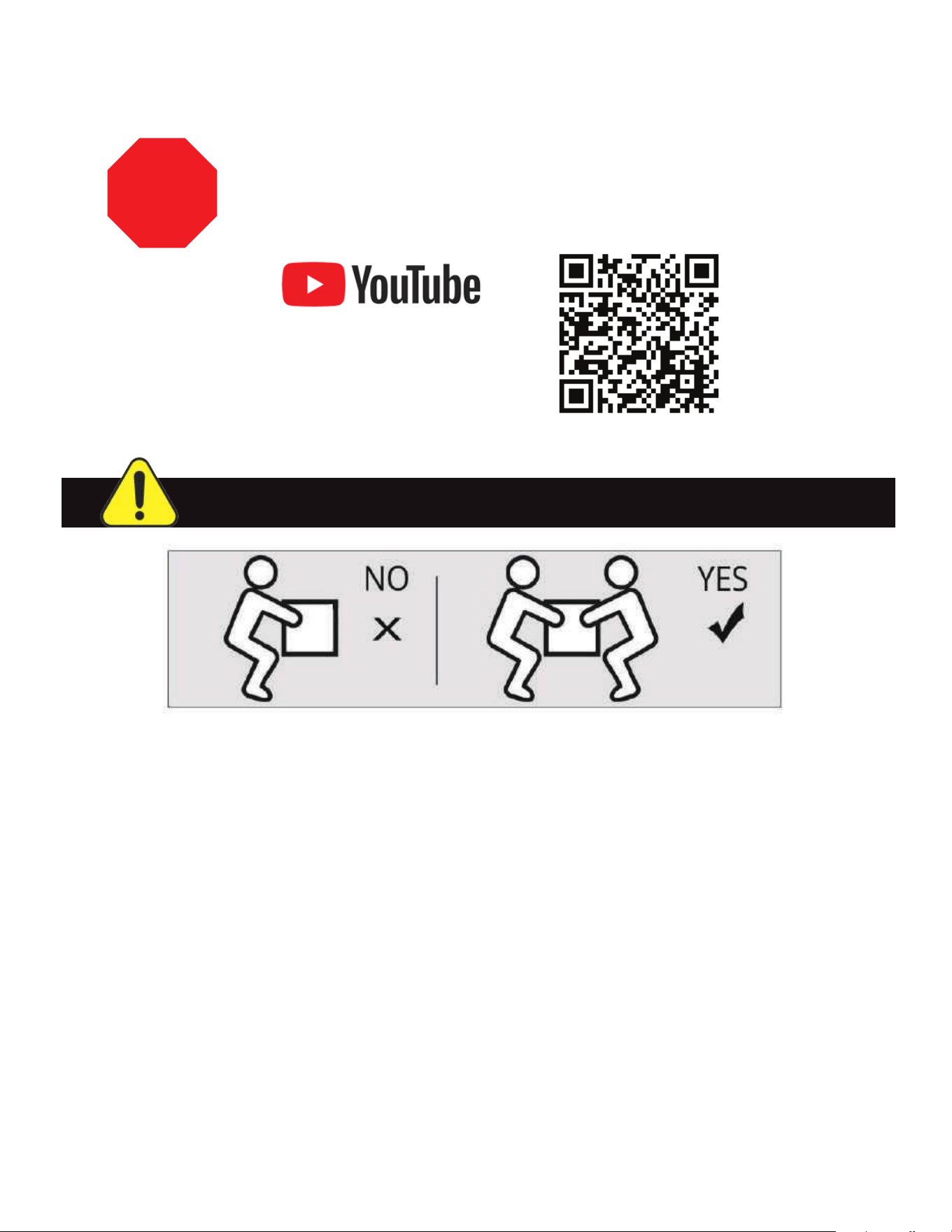
WARNING: HEANY WEIGHT HAZARD - TEAM LIFT!
As you unbox your new grill, please take a moment to make certain all the parts
are included and there was no damage in shipping.
Need Help or Spare Parts? For fastest service contact XO at 973-403-8900 or
visit www.xoappliance.com. Do not return to the dealer.
Please recycle when you dispose of the packing materials.
One of the fastest and easiest
ways to get help is to visit our
YouTube Channel which has
lots of useful How To videos -
Just scan the QR Code or go to
https://www.youtube.com/channel/UCT-Ip-dM9hoPydpxZfrZzRA
STOP
6
THIS MANUAL MUST REMAIN WITH THE PRODUCT OWNER FOR REFERENCE
THE FOLLOWING PRODUCTS ARE COVERED IN THIS MANUAL:
IMPROPER INSTALLATION, ADJUSTMENT, ALTERATION, SERVICE OR MAINTENANCE CAN CAUSE
PROPERTY DAMAGE, INJURY, OR DEATH. READ THIS MANUAL THOROUGHLY BEFORE INSTALLATION
USE OR SERVICING OF THIS EQUIPMENT.
This manual must remain with the grill. Check local building codes for proper method of installation. In the
absence of local codes, this unit must be installed in accordance with the National Fuel Gas Code NO. ANSI
Z21.58D-2002 USA or CAN/CGA-B149.1/2 Natural Gas/Propane Code (Canada), latest edition of National
Electrical Code CGA 1.6b2005 or latest edition.
Please note, pictures and other information may change without notice.
INSTALLATION, CARE AND USE OF YOUR
XO PERFORMANCE XLT COOKING PRODUCT
N OTE T O IN S T A L L E R
XOGRILL40XLT2 (L/N) XOGRILL32XLT2 (L/N)
7

WHERE THINGS ARE
Product Registration................................................................................................................. 2-3
Warnings................................................................................................................................... 4
Models.........................................................................................................................................
Specifications.............................................................................................................................
Dimensions............................................................................................................................
Safety.........................................................................................................................................
Grill Location - Clearances.........................................................................................................
Factoring in Wind Direction........................................................................................................
Overhead Construction..............................................................................................................
Outdoor Rated Hoods................................................................................................................
Cutout Dimensions.....................................................................................................................
Insulated Jacket Installation.......................................................................................................
Outdoor Island Venting..............................................................................................................
Electrical Hook Up...............................................................................................................
Before your Gas Hook Up...................................................................................................
Natural Gas Installation.......................................................................................................
Propane Tank Installation...................................................................................................
Grilling Safety............................................................................................................................
Lighting your grill safely........................................... ........................................................... 29 -
Cooking and Grilling Tips................................................................................................... 32 -
Cleaning and Maintenance.................................................................................................
Wiring and Bulb Replacement................................ ...........................................................
Trouble Shooting........................... .....................................................................................
Parts and Obtaining Service...............................................................................................
Warranty.....................................................................................................................................
5
Link - How To Videos................................................................................................................... 6
.... .....................................................................................................................serutaeF tcudorP
9
10
......11
12
13
14
15
16
17
18
19
20 - 21
22 - 23
24 - 25
26 - 27
28
31
33
34 - 37
38 - 39
40 - 41
42 - 46
47
7
8
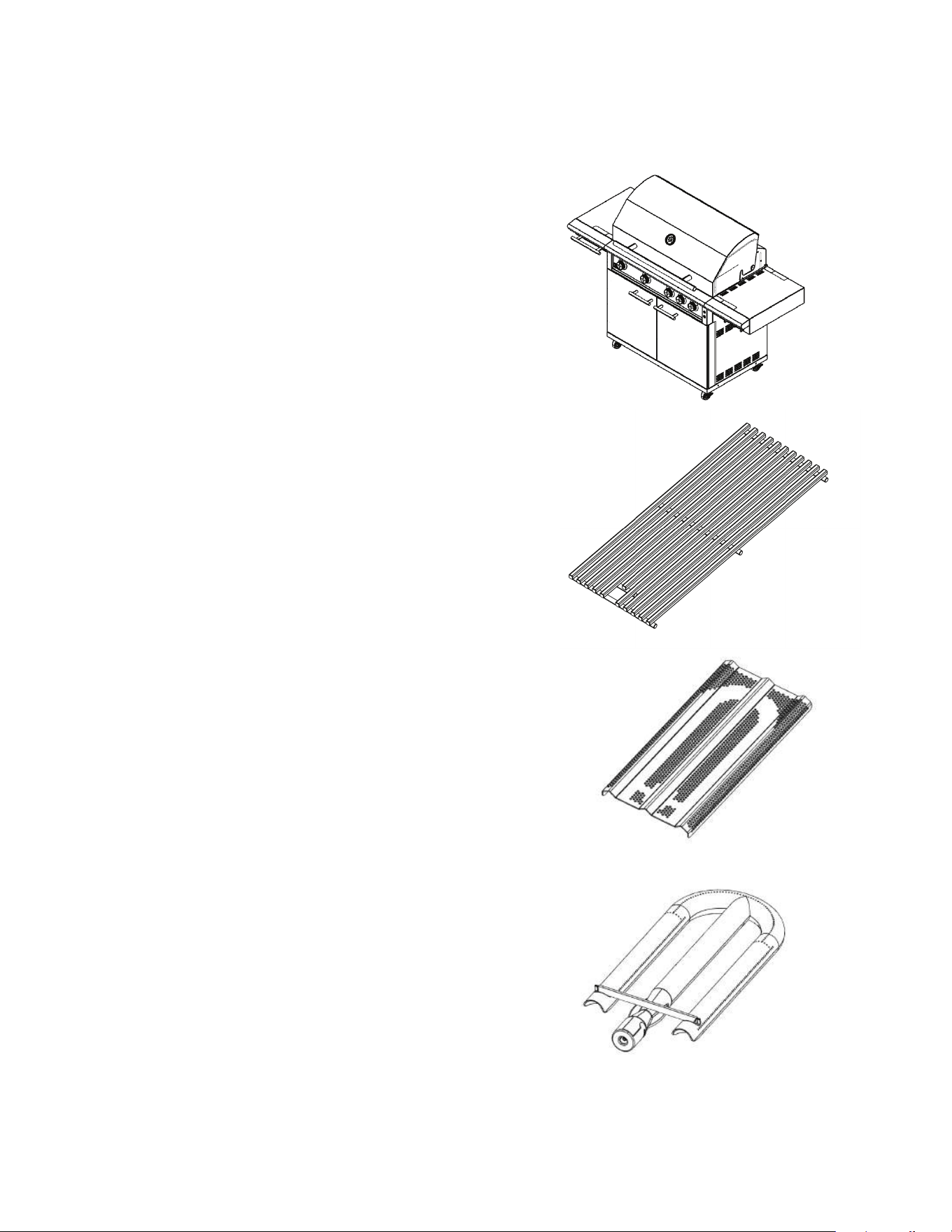
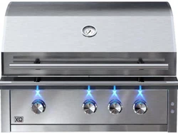
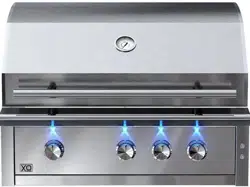
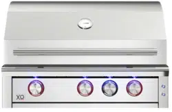
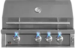
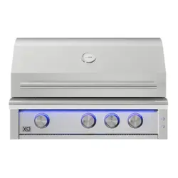
The XO gas grill has some of the most unique grilling
features that will enhance your grilling experience and
make you that “Master Chef”.
These Features include; Massive Stainless Steel Grates,
Full Coverage Stainless Steel Flame Tamers, and Heavy
Duty High Output Stainless Steel Burners.
All together this grilling machine is built to impress
the most demanding cooks.
The grates are all welded heavy duty, stainless steel
square bar stock - designed to adsorb more heat and
deliver it back in the form of strong grill marks.
The Full Coverage Stainless Steel Flame Tamers perform
triple duty by safeguarding the burners from drippings,
and then vaporizing them to create the amazing smokey
flavor of the grill - all while helping to distribute heat more
evenly within the fire box.
The powerful, heavy gauge Stainless Steel “U” burners
deliver up to 18,000 BTUs each to heat up fast and keep
pace with your hungriest guests.
These burners are lifetime warrantied.
MEET YOUR XO
UNIQUE FEATURES AND BENEFITS
9

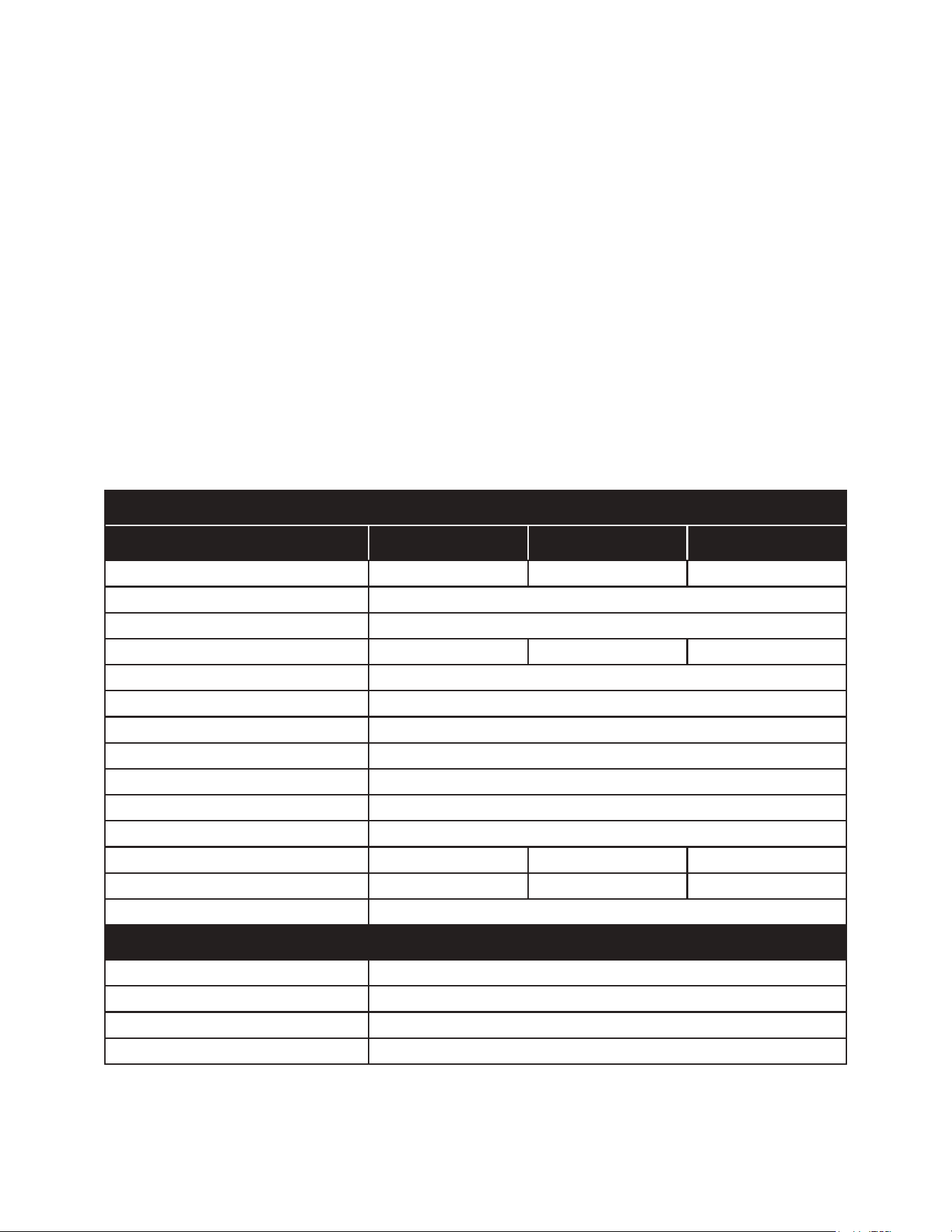
DESCRIPTION XOGRILL32XLT2 XOGRILL40XLT2
Main Cooking Area Sq. In.
Warming Rack Sq. In.
Total Cooking Area Sq. In.
Gas Type (specify)
Orifices Main Burners NG
Orifices Main Burners LP
Orifices Rear Burner NG
Orifices Rear Burner LP
Main Burners
Main Burner BTUs (each / total)
Cooking Grates
Warming Rack
Flame Tamers
Heat Zone Dividers
Rear Burner
Rear Burner BTUs
Rotisserie Kit
Hood Assembly
Spring Counter Balanced
Control Panel
Drip Tray
Ignition
Temperature Gauge
Control panel Lighting
Interior Work Lighting
Grill Cutout Dimensions
530
172
702
NG or LP
1.98 mm
1.18 mm
1.5 mm
1.1 mm
(3) Tubular SS
17,000 / 51,000
(4) 18” x 7 3/8” SS
Tilt and Store SS
(3) Full Coverage SS
(2) Removable SS
Ceramic InfraRed
10,000
Optional
Welded Stainless
Yes
Welded Stainless
Welded Stainless
Reliable Flame Thrower
Hood Mounted
12v Blue LED
12v Halogen (2)
8 1/2” x 21 1/4” x 30 5/8”
662
210
872
NG or LP
1.98 mm
1.18 mm
1.5 mm
1.1 mm
(4) Tubular SS
17,000 / 68,000
(5) 18” x 7 3/8” SS
Tilt and Store SS
(4) Full Coverage SS
(3) Removable SS
Ceramic InfraRed
10,000
Optional
Welded Stainless
Yes
Welded Stainless
Welded Stainless
Reliable Flame Thrower
Hood Mounted
12v Blue LED
12v Halogen (2)
8 1/2” x 21 1/4” x 38 3/8”
SPECIFICATIONS OVERVIEW
10
The serial number can be located on the rating plate which is located on the left side of the grill or on the pull-
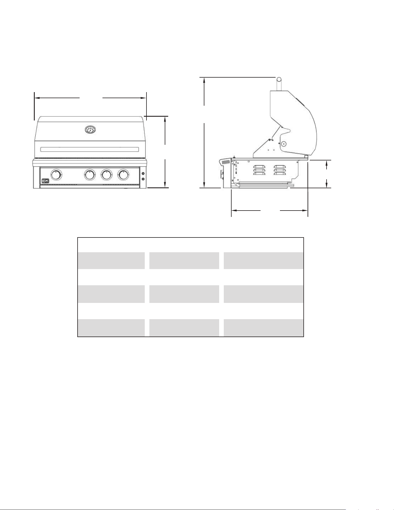
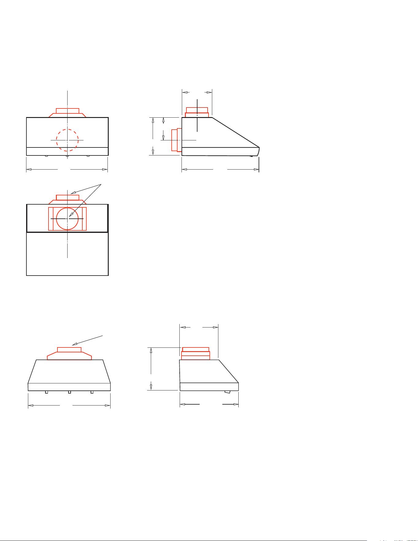
PRODUCT DIMENSIONS
11
W
H1
D
H2
H3
WIDTH (W)
DEPTH (D)
HEIGHT 1 (H1)
HEIGHT 2 (H2)
HEIGHT 3 (H3)
39 3/4”
25 3/4”
22 7/8”
32 1/4”
8 7/16”
32 3/4”
25 3/4”
22 7/8”
32 1/4”
8 7/16”
XOGRILL40XLT2 XOGRILL32XLT2

Read this manual carefully and completely before installing and using your grill to reduce the risk of fire, burn
hazard or other injury and to ensure proper installation and servicing.
Never use rusted, dented or damaged propane cylinders. Never store additional or empty propane cylinders
in the grill cabinet or in the vicinity of this or any other gas or electrical appliance. Do not store propane cylinders
indoors or on their sides for gas may escape. Gas cylinders are highly flammable.
Children should never be left unsupervised in areas where a grill is located. Place your grill well away from areas
where children play. Do not store items that may interest children in or around the grill, in the cart or in the
enclosure or Island.
Never move a grill when hot. When in use portions of the grill are hot enough to cause severe burns.
Always maintain the required clearances as detailed in this manual. The grill is designed for outdoor use only.
Never use in any garage, building, shed, breezeway or other enclosed area. Do not use this grill under any
unprotected overhead combustible construction. Combustible material exposed to heat will catch on fire.
XO Grills are not designed or certified for and are not to be installed in or on recreational vehicles, portable
trailers, boats or any other moving installation. XO Grills are for residential use only.
Always have a Fire Extinguisher accessible - never attempt to extinguish a grease fire with water or other liquids.
Store your grill in a well-ventilated area. If stored indoors, detach and leave the LP cylinder outdoors in a well-
ventilated area away from heat and where children cannot tamper with it. Always store tanks outdoors.
Keep any electrical supply cord and the fuel supply hose away from any heated surfaces. Electrical cords
should be placed away from walkways to avoid tripping hazards and must be protected by a GFI circuit.
Do not repair or replace any part of the grill unless specifically recommended in this manual. All other service
must only be performed by a certified and qualified BBQ technician.
For hard piped installations, your professional installer must show you where your gas supply shut-off is located
and instruct you in it’s use. All gas lines must have a quick shut-off that is readily and easily accessible. If you
smell gas, check for gas leaks immediately. Check only with a soap and water solution. Never check for gas
leaks with an open flame.
During any pressure testing of hard piped systems, outdoor cooking appliances and individual shutoff valves
must be disconnected from the gas supply piping system at test pressures in excess of 0.5 psi (3.5 kPa).
If using an LP gas supply hose, inspect prior to each use of the grill. If there is any evidence of excessive wear,
abrasion, cuts, or cracking it must be replaced before using the grill.
YOUR SAFETY MATTERS
WARNING: READ AND FOLLOW ALL SAFETY PRECAUTIONS
12
BUILT-IN INSTALLATIONS | NON-COMBUSTIBLE CONSTRUCTION
The XO Built in grills are designed for easy installation into a non-combustible masonry island. In installations
of this type, non-combustible materials like brick, stone or cement board completely surround the appliances
supported by block or metal framing.
To be considered non-combustible, no materials shall be used within 14” of the unit that will burn or be affected
by the high heat the unit can produce.
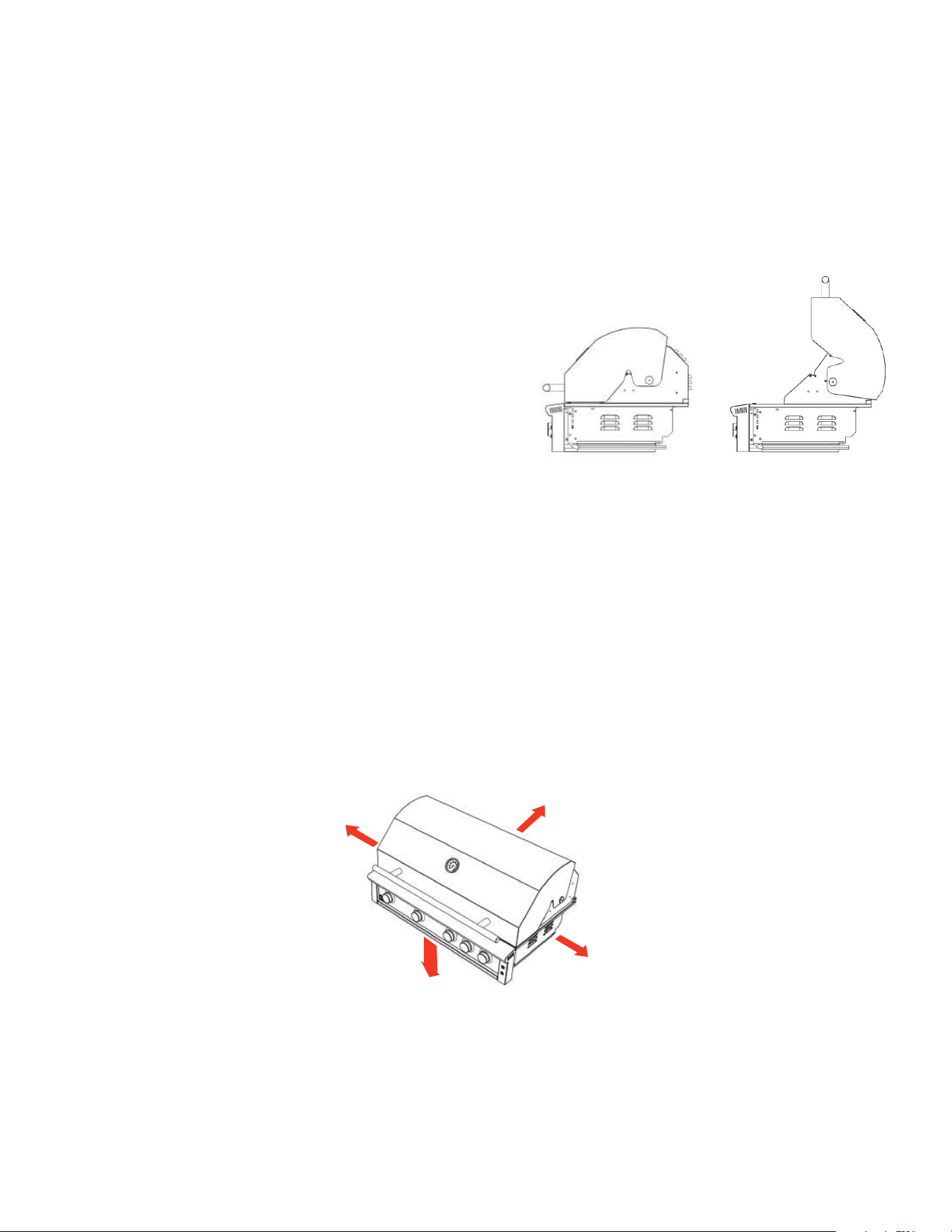
The grill slides into the cutout opening of the island and is
supported by the flanges that surround the grill sides and rear.
Do not grout the unit in place so that it can be removed for
maintenance.
In addition to 14” non-combustible materials clearance in all
directions; proper hood operation requires a 5” clear space
minimum behind the unit.
INSTALLATIONS | COMBUSTIBLE CONSTRUCTION
Built-In construction which employs some combustible materials is permitted providing certain additional
requirements are met.
Combustible materials include any surface or framing materials which may ignite, burn, support combustion,
emit smoke or melt when exposed to heat.
An approved, insulated jacket designed to shield each gas appliance must be used. All minimum clearances
to adjacent combustible construction must be increased to 14” on all sides and 16” to the rear of the grill.
These minimum clearances also apply to the placement of a portable / cart mounted grill.
CLEARANCES TO
COMBUSTIBLE
SIDES
REAR
BELOW
NEVER INSTALL OR USE YOUR GRILL IN ANY ENCLOSED SPACE SUCH AS, BUT NOT LIMITED TO, GARAGES,
PORCHES OR BREEZEWAYS.
NEVER USE YOUR GRILL ON ELEVATED PATIOS OR DECKS.
NEVER INSTALL OR USE UNDERNEATH UNPROTECTED OVERHEAD CONSTRUCTION.
14”
16”
14”
GRILL LOCATION & CLEARANCES
MAINTAIN 5”
CLEAR BEHIND
THE GRILL
14”
14”
14”
16”
13
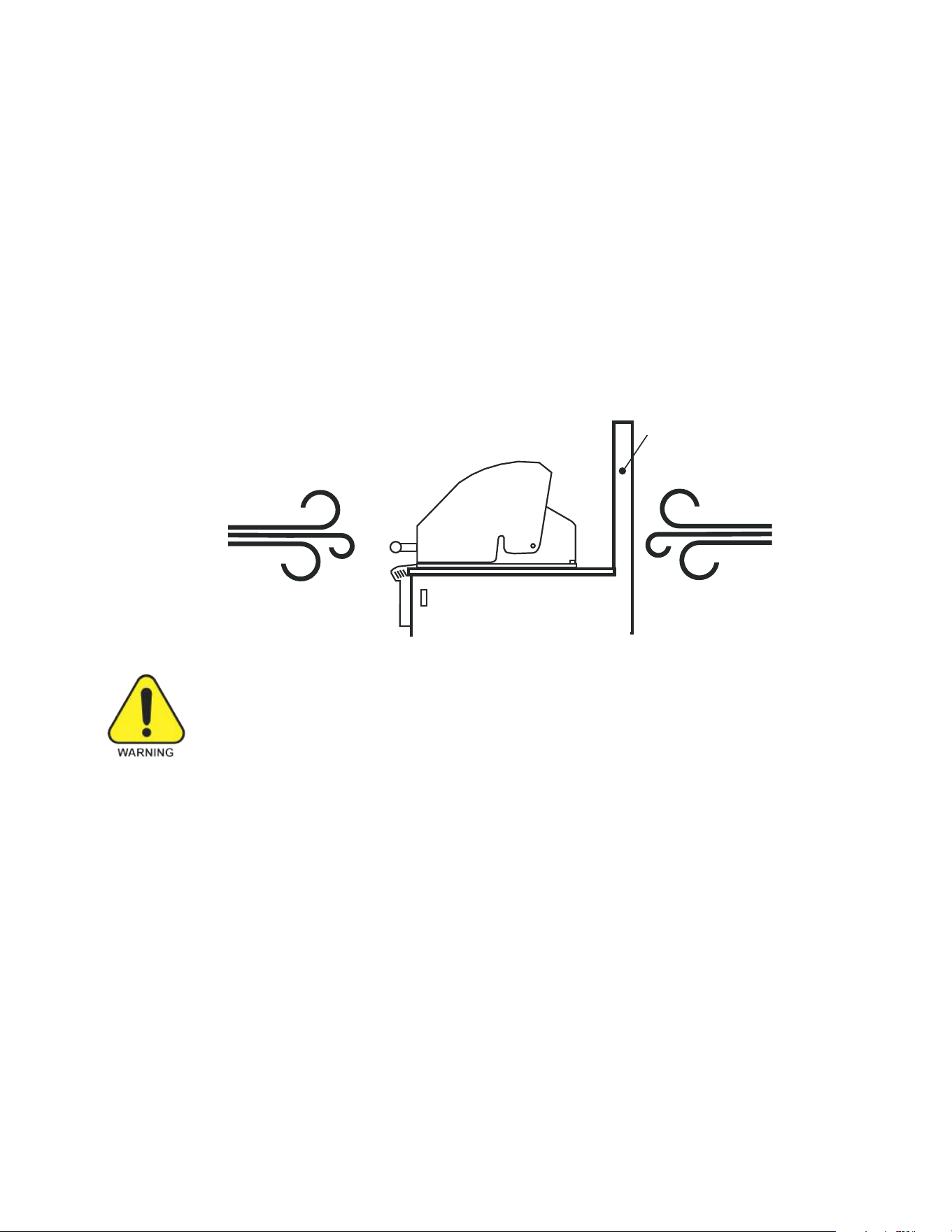
GRILL LOCATION & WIND
WHERE IS THE WIND COMING FROM?
When
traffic patterns.
If you have a free standing grill, position it so the prevailing wind blows toward the front control panel
(at your back when grilling). This will support the proper front to rear of airflow required for proper
operation of your grill.
Built-in grills located in areas with prevailing winds should be protected by a wind barrier positioned
behind the appliance. All clearances must be observed for safe operation.
FAILURE TO COMPENSATE FOR PREVAILING WIND CAN RESULT IN EXCESSIVE
HEAT BUILD UP AND RESULT IN DAMAGE TO THE APPLIANCE AND RISK OF
FIRE, PROPERTY DAMAGE OR PERSONAL INJURY.
If you suspect the grill is overheating, using an heat resistant mitt, open the hood. After first checking
the control knobs for excessive temperature, turn them down to a lower setting.
If you have a freestanding grill - turn it OFF, and after allowing it to cool, reposition the grill based on
prevailing wind patterns as described above.
OR - install a wind break to prevent the wind from interfering with the correct front to back exchange of air.
On windy days, do not operate the grill on high with the hood closed for more than 15 minutes.
Never leave your grill unattended while operating.
Your XO Grill must draw air in from the front and exhaust heated air from the rear in order to operate.
.
Position your grill so that smoke and exhaust will not gain access to the house through open windows,
doors, or ventilation.
selecting a sui
table location, consider important factors such as exposure to the wind and foot-
WIND
BREAK
REQUIRED
CORRECT
WIND
DIRECTION
WIND BREAK
14
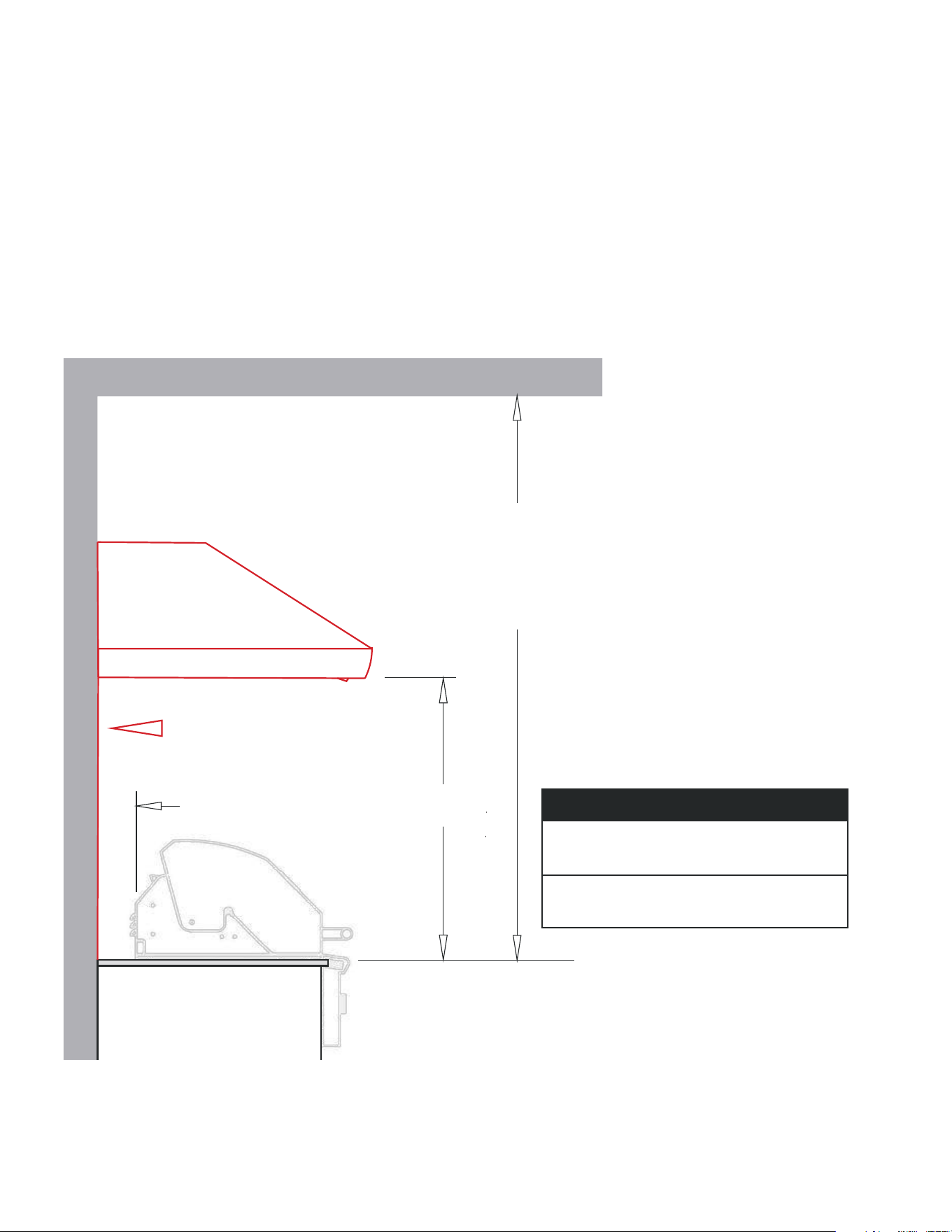
OVERHEAD CONSTRUCTION
•
If installed under any combustible construction the area above the cooking surface of the grill must
be covered with an approved exhaust hood.
•
It is highly recommended the hood be sized with a minimum 3” overhang on all exposed sides.
•
The exhaust hood shall provide no less than 1,200 CFM of proper exhaust ventilation.
•
The exhaust hood must be approved for outdoor installation and used with a dedicated GFCI branch
circuit.
5”
min.
30” to 36”
We recommend oversizing the hood by 3" on
each side to maximize efficiency and capture
space
For example;
A 36" Grill would require a 42" Hood
NON-COMBUSTIBLE
REAR WALL
OVERHEAD CONSTRUCTION
TYPICAL EXHAUST HOOD INSTALLATION
OBSERVE ALL MINIMUM CLEARANCES
Non-Combustible Construction
Sides 12” Back 5”
Combustible Construction
Sides 14” Back 16”
Combustible Overhead Construction
Must Be Protected By An Approved Hood
Use Of An Approved Hood Is Highly
Recommended With Non-Combustible
Overhead Construction
60” MINIMUM
ABOVE
COOKING SURFACE
TO
NON-COMBUSTIBLE
OVERHEAD
15
MODEL: XOGV42S
42” Wide - use with XOGRILL32XLT2
MODEL: XOGV48S
48” Wide - use with XOGRILL40XLT2
13 1/2”
18”
W
10” Dia.
33”
7 7/16”
OUTDOOR RATED VENTILATION
AVAILABLE IN 3 SIZES: 36” | 42” | 48” TWO STYLES: WALL MOUNT and INSERT
WALL MOUNT (XOGV__S):
INSERT (XOGVIL__S):
All XOGV Models have the following features:
Top or Rear Venting
304 Stainless Steel Construction
Professional Stainless Steel Baffle Filters
Four LED Lamps
Rotary Controls
Two High Velocity Blowers - up to 1,200 CFM
Matching SS Top Duct Cover
MODEL: XOGILV42S
40 1/2” Wide - use with XOGRILL32XLT2
MODEL: XOGILV48S
46 1/2” Wide - use with XOGRILL40XLT2
W
10” Dia.
15”
16 1/8”
22 9/16”
All XOGVIL Models have the following features:
Top Venting
304 Stainless Steel Construction
Professional Stainless Steel Baffle Filters
Four LED Lamps
Rotary Controls
Two High Velocity Blowers - up to 1,200 CFM
16
The installation must conform with all local code or, in the absence of local codes, with either the National
Fuel Gas code ANSIZ223.1/NFPA 54 or the National Gas and Propane Installations code, CSA B149.1, or
the Propane Storage and Handling code, CSA B149.2.
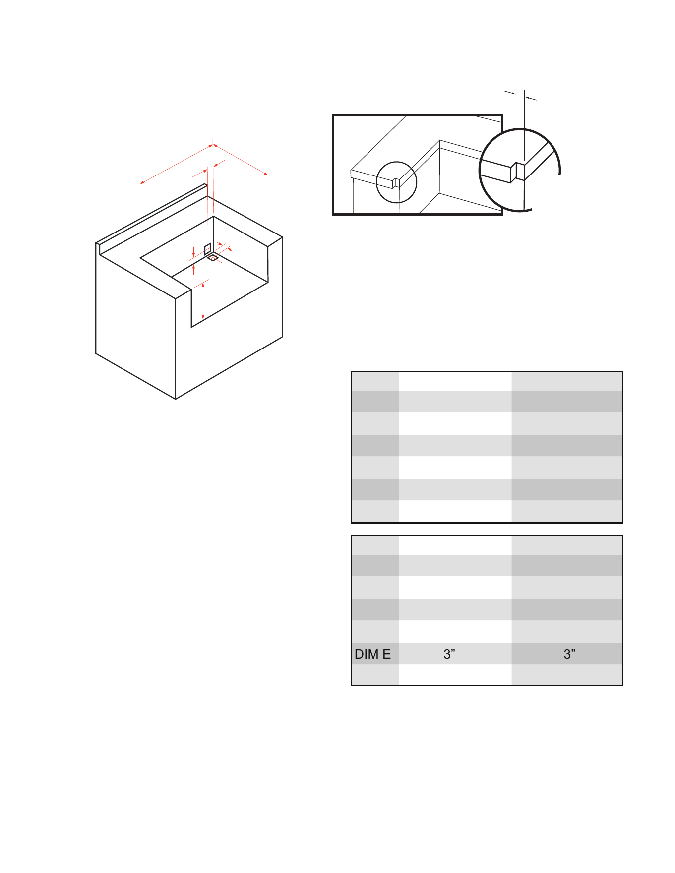
OUDOOR KITCHEN CUTOUTS
CUTOUTS FOR GRILL
NON COMBUSTIBLE CONSTRUCTION
CUTOUTS FOR INSULATED JACKET
COMBUSTIBLE CONSTRUCTION
Use of an Insulated Jacket is Required
XOGRILL32XLT2 XOGRILL40XLT2
DIM A
DIM B
DIM C
DIM D
DIM E
DIM F
8 1/2”
21 1/4”
30 5/8”
2 3/4“
2 3/4”
2 3/4”
8 1/2”
21 1/4”
38 3/8”
2 3/4“
2 3/4”
2 3/4”
XOG32JACKETXLT XOG40JACKETXLT
DIM A
DIM B
DIM C
DIM D
DIM E
DIM F
9 1/2”
21 7/8”
33 1/2”
3“
3”
3 5/8”
9 1/2”
21 7/8”
40 3/4”
3“
3”
3 5/8”
A
B
C
E
D
F
Dimensions D, E and F define the center lines
for 4” x 4” openings for the gas and electrical
utilities to be brought in.
9/16”
Notch Detail
when countertop
is overhung
17
INSULATED JACKET INSTALLATION
18
Never install this product into a structure built using combustible materials without an insulated jacket.
Doing so risks Fire, Property Damage, Injury or Death.
Observe and follow ALL set backs and clearances set forth in this manual.
For outdoor installation only. Never install or operate in an enclosed space.
Observe and follow ALL overhead clearances set forth in this manual.
Installation must conform with local codes or, in the absence of local codes, with either the National Fuel Gas
Code, ANSI Z223.1/NFPA 54, Natural Gas and propane Installation Code, CSA B149.1, or Propane Storage
and Handling Code, B149.2, in Canada.
CAUTION
IMPORTANT: Before you build the frame, you must take into account the total weight of the jacket, grill, other
appliances, countertop and all other finishing materials.
XO Outdoor cooking appliances operate at very HIGH TEMPERATURES. It is absolutely essential to install an
insulated jacket whenever combustible materials are used in the construction of your outdoor kitchen. Failure
to isolate the cooking appliances within an approved insulated jacket can result in fire, property damage,
personal injury or death. Combustible materials include anything which will burn, emit smoke, melt or support
combustion.
Refer to the table on page 18 for the correct dimensions to install the insulated jacket..
Determine the entry point for your gas and electrical connections. Create your 4” x 4” rear or bottom utility access
based on location requirements.
Use a carpenter’s level to ensure the framing is level both side to side and front to back.
NEVER under any circumstances run the gas line or electrical wiring between the grill and the insulated
jacket. All excess electrical wire leads must be pulled out beyond the insulated jacket. Never attempt
to install the transformer between the liner and grill.
LINER INSTALLATION
Position the liner in the frame. No part of the combustible construction can protrude above the top or beyond
the front surface face of the liner. Shim the liner as necessary.
APPLIANCE INSTALLATION - CAUTION HEAVY LIFT
Remove the grates from the grill to reduce its weight and using two people, place the grill into the liner. The side
and rear flanges of the grill are designed to rest on top of the stainless flanges of the liner without additional
fasteners. The grill must be able to be removed for maintenance and service, do not grout the grill in place.
FINISHING
If desired the gap, if any, between the jacket and the countertop may be filled with a non-combustible sealant.
.
.
.
.
.
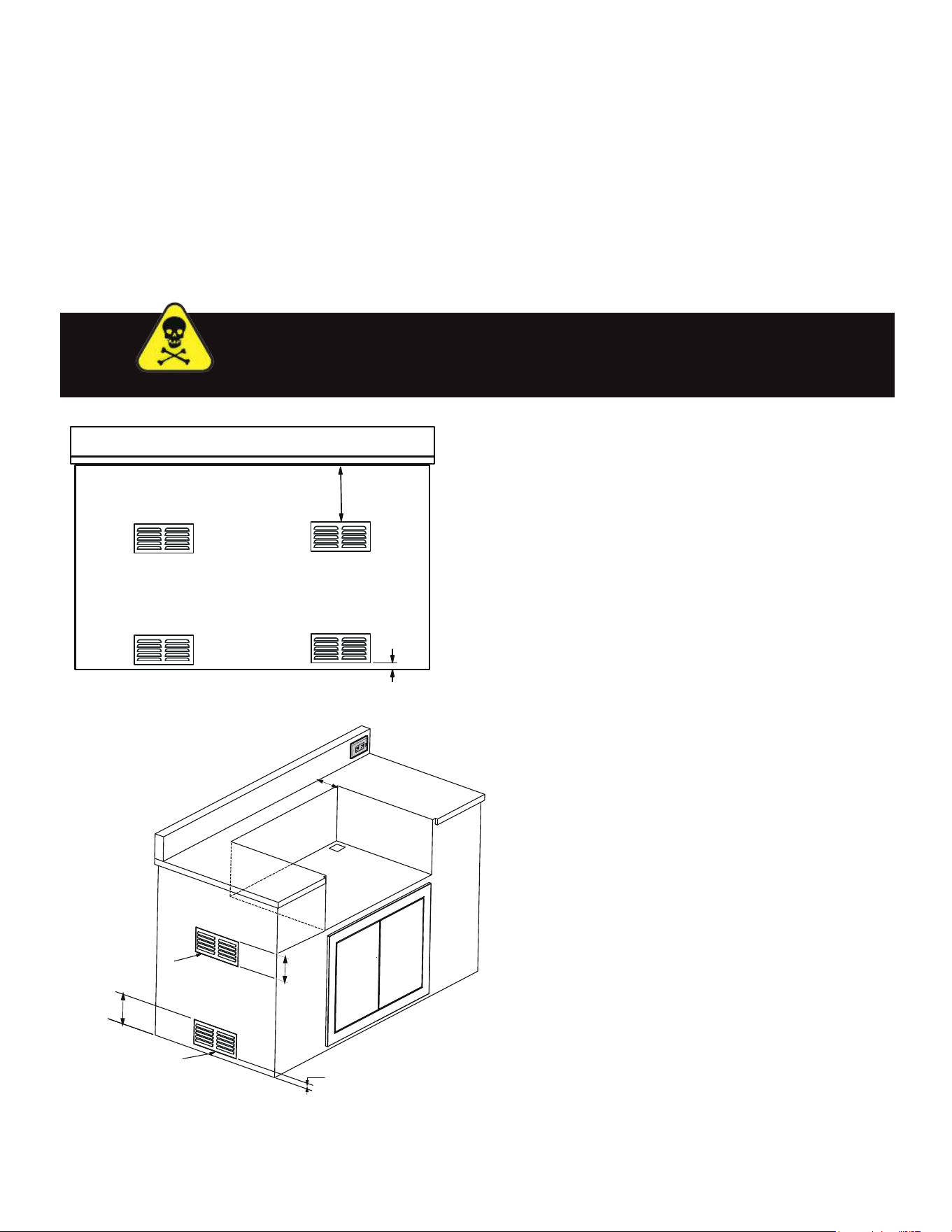
OUTDOOR KITCHEN VENTING
REQUIRED FOR ALL OUTDOOR KITCHEN INSTALLATIONS
Proper venting is essential for all installations regardless of the materials of construction.
1. Correctly installed venting helps ensure adequate airflow necessary for combustion to take place
safely.
2. AND properly installed cross ventilation helps ensure that, in the event of a leak, gas is not trapped
within the enclosed space inside.
Gas leakage within a confined space poses an extreme danger
of fire and/or explosion.
Adequate cross ventilation is absolutely essential.
NON-COMBUSTIBLE MATERIAL
NON-COMBUSTIBLE MATERIAL
MINIMUM 20 SQ IN
OF VENTILATION
REQUIRED ON EACH END OF
CABINET.
MINIMUM 10 SQ IN
OF VENTILATION REQUIRED ON
EACH END OF CABINET.
5"
MAXIMUM
5"
MAXIMUM
1"
MAXIMUM
Min 7"
Natural Gas is lighter than air.
Vents should be placed 10” below the countertop.
Propane is heavier than air.
Vents should be placed 1” minimum
above ground
level.
10”
1”
Minimum of three 10 in² (65 cm²) ventilation
openings must be provided at the bottom of
the back, left and right sides of the enclosure.
Minimum of three 20 in² (130 cm²) ventilation
openings must be provided at the top of the
left, right and back sides of your enclosure
where the top of the opening aligns with the
bottom of the grill cut-out.
Vents are required to safely dissipate gas
vapors if there is a leak in your enclosure.
EXAMPLE
DANGER
19
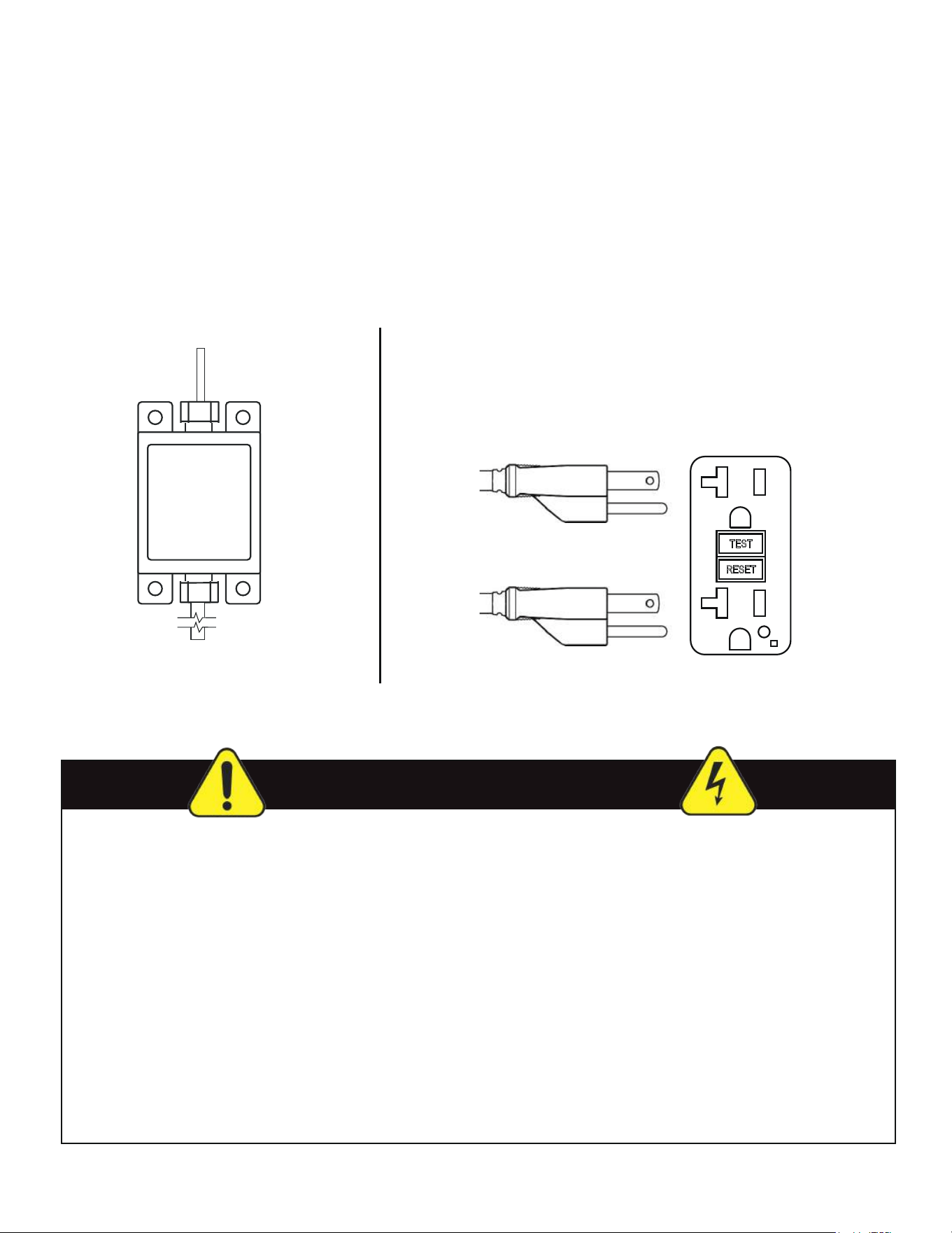
The Halogen and LED lighting system is powered by a 60W transformer included with the grill. It
must be mounted with the three prong cord set pointing down so the grill wiring harness connects at
the top screwing in place to make a water tight connection. All wiring must be routed away from all hot
surfaces and gas lines.
NOTE: In order for the rotisserie, LED and halogen lights to work the rotisserie motor and grill must
each be plugged into a properly grounded GFCI outlet installed by an electrician.
The transformer comes with a 63” long cord - The lead length coming from the grill is 48”
ELECTRICAL HOOK UP
WARNING ELECTRICAL SHOCK HAZARD
TO GRILL TRANFORMER
TO ROTISSERIE
OUTDOOR
RATED
GFCI
OUTLET
60W
TRANSFORMER
TO GRILL
LIGHTING HARNESS
TO GFCI
OUTLET
The Flame Thrower Ignition system
does NOT require an electrical connection.
Product installation must meet local electric codes or, in the absence of local codes, the latest edition of the
National Electrical Code ANS/ NFPA No. 70 or the Canadian Electrical Code CGA 1.6b2005.
Use only a Ground Fault Interrupter (GFI) protected circuit with this outdoor cooking gas appliance.
Use only extension cords with a 3 prong grounding plug, rated for the power of the equipment, and approved
for outdoor use with a “W-A” marking.
To protect against electric shock, do not immerse any part of the power cord, an extension cord or any plugs
in water or other liquid.
Do not permit electrical cords to hang over the edge of the counter or to touch hot surfaces.
IMPORTANT: When using the rotisserie, attach the motor to the grill before plugging it in.
Unplug the Rotisserie from the outlet when not in use and before cleaning. Allow it to cool before putting on
or removing parts.
Never use an outdoor cooking appliance for other than its intended purpose.
Do not operate any appliance with a damaged electrical cord or plug.
Unplug and do not use any appliance which has malfunctioned or been damaged in any way before contacting
the manufacturer.
20
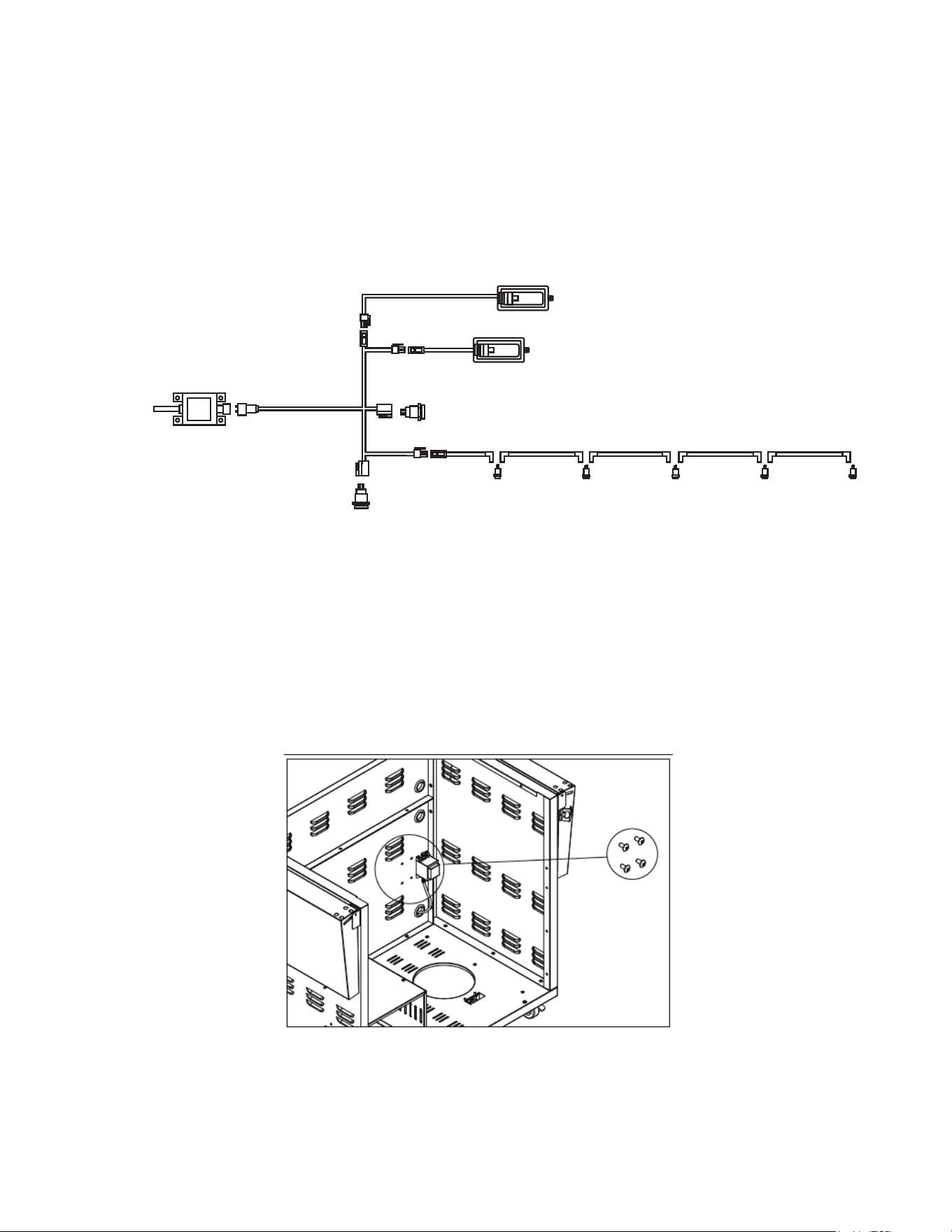
The Halogen and LED lighting system is powered by a 60W transformer included with the grill. It
must be mounted with the three prong cord set pointing down so the grill wiring harness connects at
the top screwing in place to make a water tight connection. All wiring must be routed away from all hot
surfaces and gas lines.
Shown below is a schematic of the wiring harness
The transformer comes with a 63” long cord - The lead length coming from the grill is 48”
Should bulb replacement become necessary, please refer to the maintenance section of this manual.
When installing your grill in a cart, threaded holes are located on the interior back wall of the cart
to securely mount the transformer. Consult the cart assembly instructions for complete information.
ELECTRICAL HOOK UP
ILLUMINATED PUSH BUTTON SWITCH
ILLUMINATED
PUSH BUTTON
SWITCH
HALOGEN INTERIOR LAMP
HALOGEN INTERIOR LAMP
CONTROL KNOB LED LAMPS
32” GRILL QTY (4)
40” GRILL QTY (5)
CONNECTORS
TRANSFORMER
SCREW-ON
CONNECTION
TO
GFI
OUTLET
CONNECTOR
21
Your XO gas grill is designed for use with either Natural Gas or Propane (LP).
Operation using natural gas requires different burner orifices and a different regulator set up than for propane
and vice versa. If your grill has been set up for to use one type of fuel and you wish to power it with the other
fuel - the appliance must be converted for that use. Gas conversion must only be performed by an experienced
gas appliance technician.
Every gas installation must include a readily accessible emergency shut off valve close to the grill. The valve
should be at the gas supply source outdoors after the gas line exits the outer wall of the house and before it
connects to the flex line or QD line. If the gas line is to be buried, it should connected before it enters the ground.
It is highly recommended that the valve have the ability to lock when closed to prevent accidental opening. Any
locking or sercurity device cannot interfere with the ability to rapidly c
lose the valve in an emergency. Some
locations require this locking feature by code.
XO Grills are shipped as specified by the customer set up for use with Natural Gas or Propane. This is
designated by the last letter of the model number. Confirm the correct fuel type before installation.
If the model number ends with “L” the unit has been set up to burn Propane.
If the model number ends with “N” the unit has been set up to burn Natural Gas.
In either case, the unit is shipped with the appropriate regulator. Natural Gas regulators operate with an outlet
pressure of 4 “ W.C. and Propane regulators operate at 11” W.C., They are not interchangeable.
All threaded fittings must be properly sealed with pipe compound or tape with has been approved for use on
gas systems. All connections must be leak tested either with a leak detector or by performing a bubble test using
a 50/50 mixture of liquid soap and water. This method is fully explained in this manual.
During gas system pressure testing, (equal to or exceeding 1/2 PSI - 3.5 KPa), the gas grill must be disconnected
from the supply using the isolation shut-off valve.
HOWEVER, it must be set up correctly to use one or the other fuel.
Different fuels cannot be used interchangeably.
BEFORE CONNECTING TO YOUR GAS SUPPLY
WARNING
22
Regardless of whether you are powering your grill with Propane or Natural Gas - Leak Testing of all connections
and components is an essential step to ensure the safe use of the appliance.
Leak testing is easy to do and MUST be performed: Before the First Use, whenever a gas line supply component
(such as a propane tank) is changed, whenever a gas leak is suspected, or once a year as general maintenance.
PERFORMING A LEAK TEST - Either with a leak detector or by the simple method below:
Prepare a mixture of 50% liquid dish soap and 50% water.
Remove or extinguish all open flames or potential ignition sources - NO SMOKING - whenever gas may be
present. NEVER test for the presence of gas using a match or open flame.
Sparks or open flames may ignite a fire or explosion resulting in property damage, personal injury or death!
Ensure that all control knobs are in the OFF position.
Open the local gas supply valve (either at the propane tank or natural gas line)
Using a spray bottle or brush, liberally coat ALL the gas line connections,
hoses, manifolds, regulators and valves.
Gas leaks will be indicated by bubbles forming.
If this occurs, IMMEDIATELY SHUT OFF THE GAS!
FIXING A GAS LEAK:
After shutting off the gas, turn all control knobs “ON” to purge gas from the system.
Wait several minutes - then turn all control knobs to the “OFF” position.
With a damp cloth, wash the residual soapy solution from the gas line and let dry.
Tighten the loose fitting or replace the leaking component with a Manufacturer approved part.
Repeat the leak test above.
If the unit fails the leak test a second time - STOP - Shut the gas OFF and call for a professional service technician -
DO NOT ATTEMPT TO USE THE GRILL UNTIL REPAIRED.
BEFORE CONNECTING TO YOUR GAS SUPPLY
WARNING
23
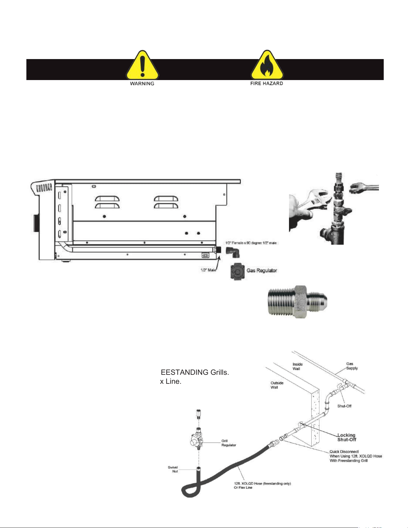
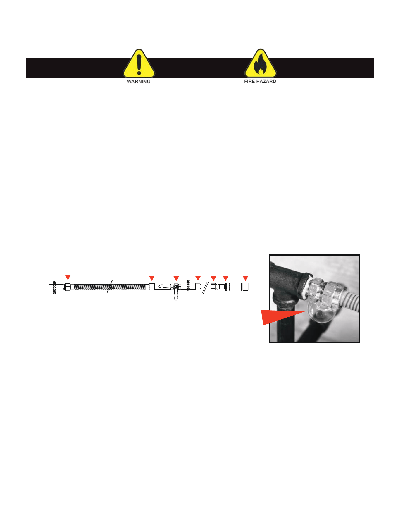
The Natural Gas Regulator and 1/2F to 1/2M brass connection is included with the gas grill. Always use a
Professional Installer when connecting to your gas line. The gas regulator which is included is set up for natural
gas but can be converted for use with propane. This conversion must be performed by an experienced professional
technician.
The gas grill manifold ends in a 1/2" male thread and has a "Grip Nut" for a wrench. When tightening these fittings,
two wrenches are required. One to hold the Grip Nut and prevent it from moving while the other wrench turns the
opposing fitting. Failure to employ two wrenches this way places an undue strain on the manifold and can cause
damage and/or result in leaks.
GAS SUPPLY HOOK UP - CONTINUED
WARNING
Use plumbers putty or gas tape on the male threads to seal the
male threads to seal the connection.
Do NOT use sealant or tape on the flare side of a connector.
Connect the gas regulator and make certain the “IN” and “OUT” are oriented correctly. This is marked in the
casting. Gas will only flow in one direction. A gas flex line or hose can be used to make the final connection to
the house supply line.
IMPORTANT:
An XOLQD Hose may only be used for FREESTANDING Grills.
Permanent installations MUST use SS Flex Line.
FINAL PIPING MUST INCLUDE A
LOCKING 1/4 TURN SHUT OFF VALVE
OUTSIDE, LOCAL TO THE GRILL
FOR EMERGENCIES.
ALL CONNECTIONS MUST BE
LEAK TESTED PRIOR TO
THE FIRST USE.
Always use two wrenches to
tighten gas fittings
L
o
r
e
SEALANT NO SEALANT
24
Only a licensed gas professional must perform the required gas fitting on XO gas appliances. To ensure
satisfactory performance, the gas supply line must be sized to accommodate the total BTU/h requirements
of all the gas-fired equipment that will be connected to that line. In no case should pipe less than 3/4” inside
diameter or 1” outside diameter ever be used to connect this product.
HARD PIPING NATURAL GAS SUPPLY
WARNING
Natural Gas Supply
Line From Source
Natural Gas
Regulator
Flexible
Gas Line
Grill Gas line Flexible
(Not Supplied)
Rigid Piping for
supply
(Not Supplied)
Securely mount the gas
supply components to the
non combustionable
structure. This illustration is for
reference only each
All Other Components
Are Not Supplied
CONTRACTORS
Natural Gas Regulator
mounted on BBQ.
ALWAYS REGULATE THE BBQ
Proper Air
Ventilation
Required
Natural Gas
Supply
Non-Combustible
Construction
Flexible
Gas Line
Natural Gas
Regulator
25
LP Gas grill models are designed to use a standard 20lb. Liquid Propane Gas (LP Gas) tank, sold separately.
This is a tank approximately 12” in diameter and 18-1/2” tall. This section deals with tanks of this type.
If connecting to a bulk LP supply system, you must follow guidelines similar to a natural gas hard piping system
- consult your propane supplier.
The 20lb. tank described above must have an Overfill Prevention Device, “OPD”, installed. This is a safety device
which prevents filling the cylinder beyond its rated capacity, which can cause the LP tank to malfunction.
The LP Gas tank must be constructed and marked in accordance with the Specifications for LP-Gas Cylinders
of the U.S. Department of Transportation (D.O.T.) or the National Standard of Canada, CAN/CSA-B339, Cylinders,
Spheres and Tubes for Transportation of Dangerous Goods, and Commission: as applicable.
The LP Gas tank must have a shutoff valve, terminating in an LP Gas supply tank valve outlet, that is compatible
with a Type 1 tank connection device. The LP Gas tank must also have a safety relief device that has a direct
connection with the vapor space of the tank. The tank supply system must be arranged for vapor withdrawal.
The LP Gas tank must have a collar to protect the tank valve. Never connect an unregulated LP gas tank to your
gas grill. The gas regulator assembly supplied with your gas grill is adjusted to have an outlet pressure of 11" water
column (W.C.) for connection to an LP gas tank. Only use the regulator / hose assembly supplied with your gas grill.
Replacement hose / regulator assembly must be identical to those listed in the parts list of this Operating Manual
as specified by XO.
Have your LP Gas dealer check the release valve after every filling to ensure it remains free of defects. Always
keep LP Gas tank in upright position. Do not subject the LP Gas tank to excessive heat. Never store an LP Gas
tank indoors. If you store your gas grill in the garage always disconnect the LP Gas tank first and store it safely
outside. LP Gas tanks must be stored outdoors in a well-ventilated area and out of the reach of children.
Disconnected LP Gas tanks must not be stored in a building, garage or any other enclosed area.
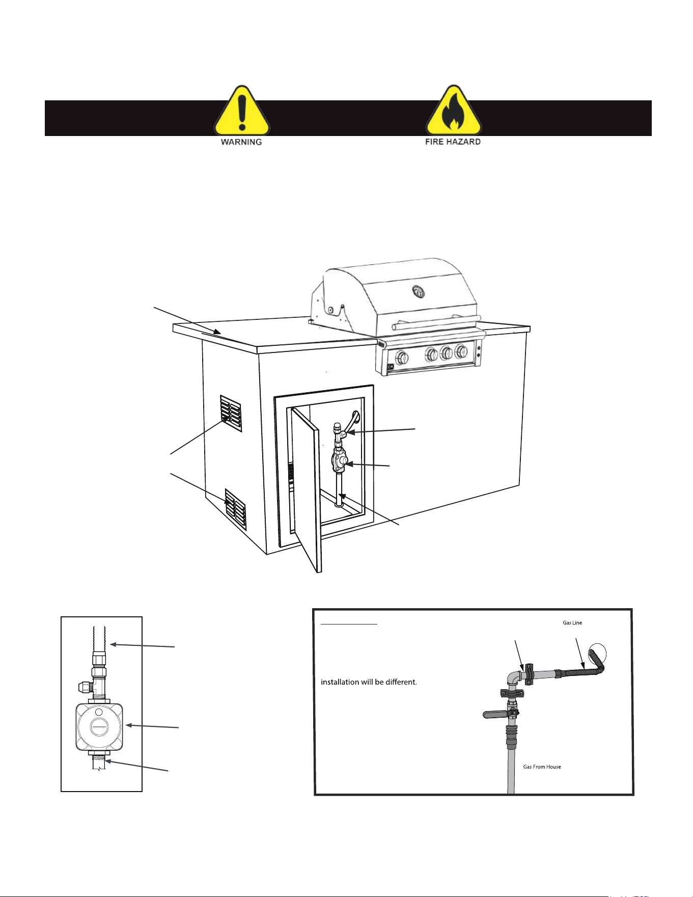
The regulator / hose assembly can be seen by opening the cart or island doors. They must be inspected before
each use of the grill. If the hose is damaged in any way, it must be replaced prior to using the grill.
The gas grill
is set up to operate with an LP gas cylinder equipped with an OPD (overfilling prevention device).
LP TANK SAFETY
NOTE: LP Tank is secured
in the cart by a bolt
which locks it in place.
SAFETY NOTICE
Always shut the tank valve when not in use.
Excessive heat can cause vapor to be
released from the cylinder when not in use.
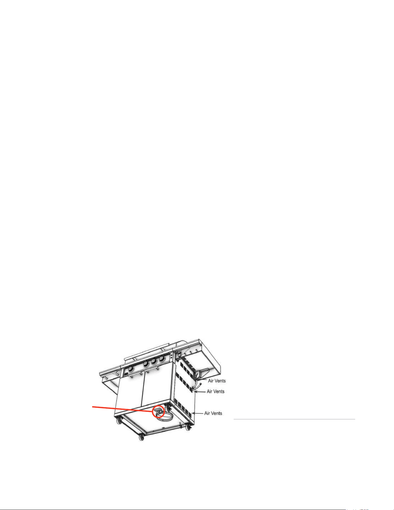
The grill cart has air vents
on three sides to allow for
the release of excess vapor.
26
Never connect any appliance directly to a gas line. The correct pressure regulator must be installed on all gas
equipment. All local codes require it. XO supplies the correct regulator with your grill. Failure to install or removal
of the gas regulator supplied with your grill can result in fire and/or serious personal injury. It will also void the
equipment warranty. Do not use any gas regulator/assemby except the one supplied for your unit by XO.
PROPANE TANKS - CONTINUED
WARNING
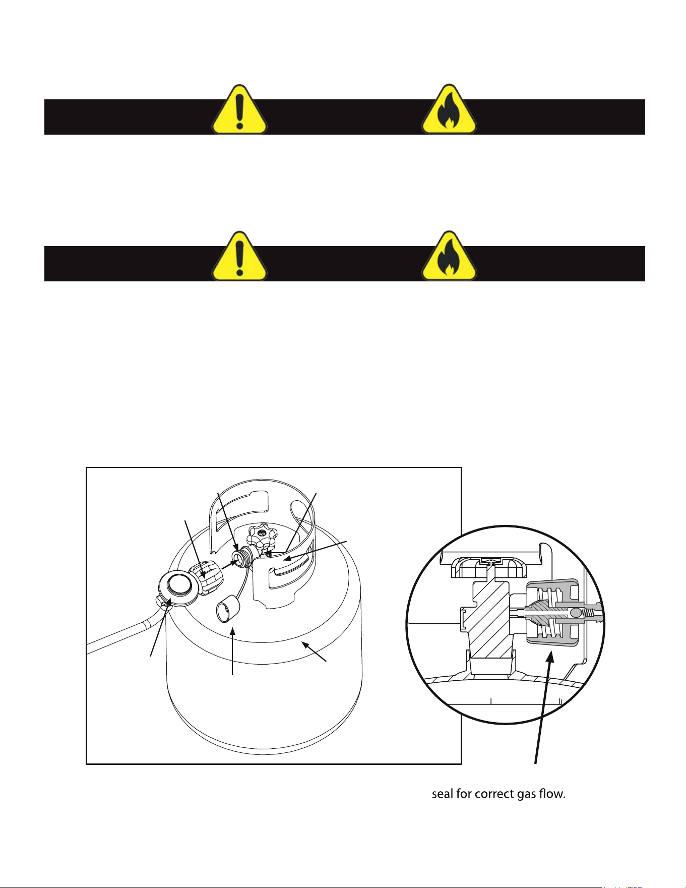
Cylinder Valve
Coupling Nut
Pressure Relief Valve
Propane Tank
Propane Dust Cap
(used when in storage
or transportation.)
Propane Regulator
(included)
Valve Protection Collar
Hand tighten to ensure proper
When not in use - shut the gas valve OFF at the tank.
Never store spare propane tanks under or near the grill.
If storing the grill indoors - remove the propane tank.
Us
e only the valve dust cap supplied with disconnected tanks.
Tanks must be stored outdoors in a secure, well ventilated area.
Never fill propane tanks beyond 80% of their rated capacity.
Hand tighten the regulator coupling nut - Do not over tighten.
.
.
.
.
.
.
.
WARNING
27

NEVER leave the grill unattended..
NEVER operate a grill that has not successfully undergone a leak test.
Prior to the first use - make certain that all packing materials and tie downs have been removed from the interior
of the grill, the grates have been washed and given a light coat of canola oil.
Avoid wearing loose-fitting garments while grilling.
Assume all surfaces are hot. Do not touch the grill racks, hood or immediate surrounding metal surfaces with
bare hands - these areas become extremely hot during use and could cause burns.
Use an insulated glove or mitt when opening and operating the grill.
Open the grill hood slowly to allow heat and smoke to escape before fully opening.
Open the grill hood fully when lighting.
Never lean over hot grill surface or look directly into the grill when lighting.
Do not heat unopened food containers.
Do not use aluminum foil to line any part of the grill. Severe damage can result and void your warranty.
Never use charcoal in this gas grill.
Excessively fatty foods can cause flare-ups. Damage caused as a result of unsupervised use or flare-ups will
void the warranty.
Never grill without the drip pan in place. Failure to ensure that the drip pan is properly inserted can result in a
grease fire.
Grease is extremely flammable. Let hot grease cool down completely before disposing of it.
The drip tray should be cleaned after every use.
Before grilling, lightly oil the grates with canola before lighting the burners and preheat for 10 minutes for best
peformance.
NEVER operate the grill under the influence of alcohol or drugs.
GRILLING SAFETY
28
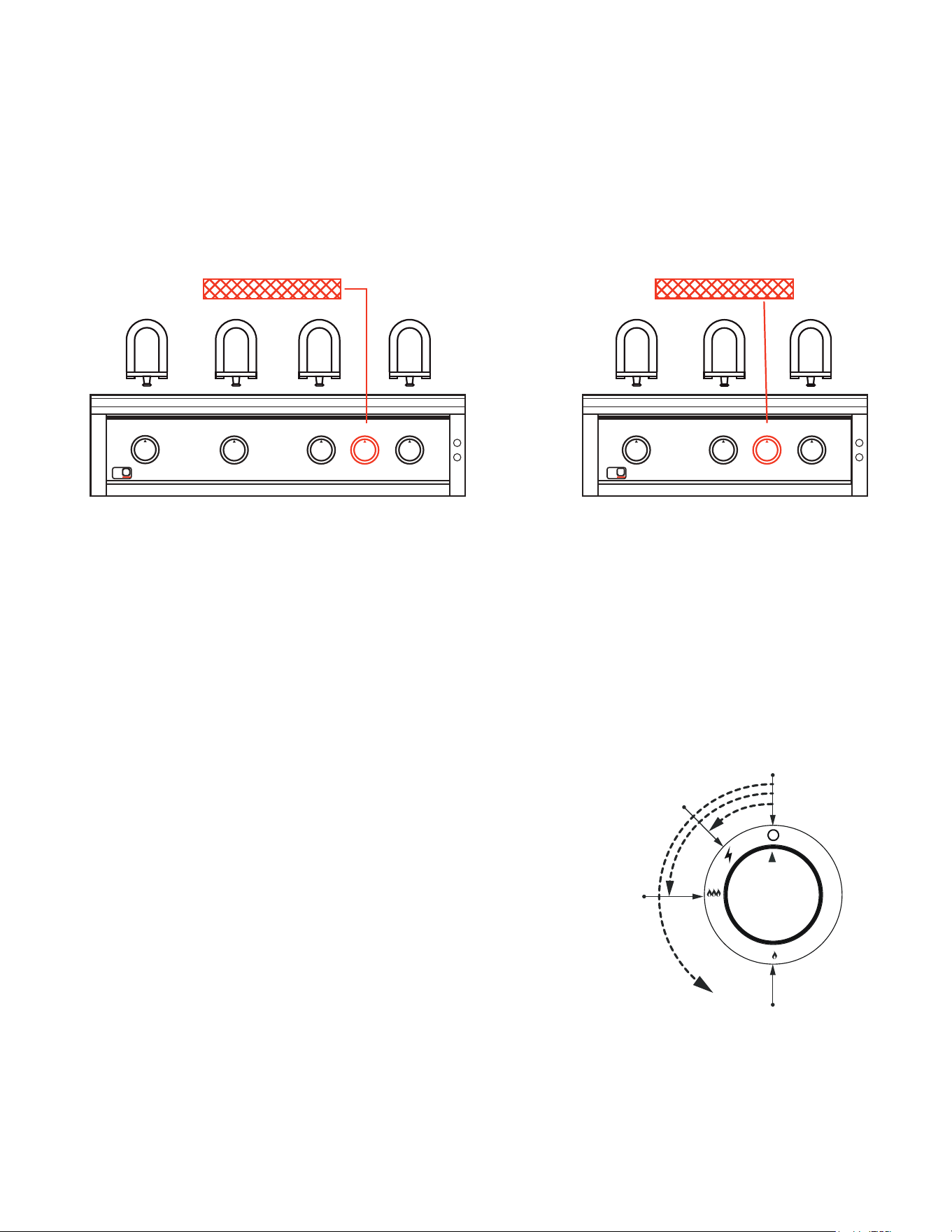
The second knob from the right controls the rear InfraRed burner used for indirect and rotisserie cooking, the
remaining knobs each control one of the main burners.
LIGHTING THE BURNERS | CONTROLS
LEFT MIDDLE MIDDLE ROTISSIE RIGHT
X
IGNITION POSITION
OFF
Ignition
Point
High
Temperature
Low
Temperature
With the hood open - Push and hold the knob in to start the flow of gas.
After 2 seconds, while holding in, turn slowly 1/4 Turn to the left.
You will hear the loud Click of the igniter.
Look to see the burner is fully lit.
If the burner does not light, turn the knob OFF
wait 5 minutes until the gas is fully dissipated
and repeat.
Always make certain all knobs are in the
OFF position when finished cooking.
X
LEFT MIDDLE ROTISSIE RIGHT
REAR BURNER REAR BURNER
MAIN BURNERS
XOGRILL40XLT2
(4) Main Burners
(1) Rear IR Burner
XOGRILL40XLT2
(3) Main Burners
(1) Rear IR Burner
29
• Always keep the hood open when lighting the grill.
• Never leave children unsupervised around the XO grill.
• Do not store items of interest to children around or below the grill or in the cabinets.
• Never allow children to crawl inside a cabinet or enclosure.
• Never light the grill if you smell gas.
• Keep face and body parts away from the grill when lighting.
• Never leave the grill unattended
LIGHTING THE BURNERS
WARNING
CAUTION
LIGHTING THE MAIN GRILL BURNERS:
1. Open grill hood. DO NOT ATTEMPT TO LIGHT THE GRILL WITH THE HOOD CLOSED.
2. Check to ensure that all burner control knobs are set to OFF.
3. Turn on main gas supply.
4. Push in and hold knob for 2 seconds
5.
After 2 seconds, while holding the knob in, turn the knob counterclockwise 1/4 turn.
You will hear the "CLICK" and the burner will ignite. Release knob.
6. If burner does not light, turn knob to OFF, wait 5 minutes for gas to dissipate, and repeat step 4.
LIGHTING THE REAR INFRARED BURNER:
1. Open grill hood. DO NOT ATTEMPT TO LIGHT THE GRILL WITH THE HOOD CLOSED.
2. Check to ensure that all burner control knobs are set to OFF.
3. Turn on main gas supply.
4. Push in and hold knob for 2 seconds
5.
After 2 seconds, while holding the knob in, turn the knob counterclockwise 1/4 turn.
You will hear the "CLICK" and the burner will ignite. Release knob.
Continue to hold the knob in for 30 seconds until the burner ignites completely, then release.
6. If burner does not light, turn knob to OFF, wait 5 minutes for gas to dissipate, and repeat step 4.
IF BURNERS ARE NOT IGNITING AFTER TWO ATTEMPTS - YOU CAN ATTEMPT TO LIGHT THE BURNERS
MANUALLY AFTER WAITING 5 MINUTES FOR GAS TO DISSIPATE.
IF THE BURNERS STILL WILL NOT LIGHT - SHUT OFF THE GAS SUPPLY & CALL FOR SERVICE
Always preheat the grill for best results.
Before beginning - wipe the top of the grates with a light coating of a high temperature oil like canola.
To preheat the grill, light all main burners and set to HIGH. Close the hood and preheat for 10-15 minutes, or
until the grill reaches desired temperature.
After preheating, turn off all burners not required, carefully open the hood, and adjust remaining burners to
desired temperature.
Do not leave the grill unattended during the preheat cycle or at any time while the grill is in use.
Do not allow grill to preheat for prolonged periods of time. Overheating the grill can cause damage to the grill
and personal property.
30
• Never attempt to light a burner if you smell gas.
• Alway keep the hood open when attempting to light a grill.
• Releasing fuel into a closed grill before lighting will increase the risk of explosion, property
damage, personal injury or death.
• Keep your face and body as far from the grill as possible when lighting. Any time a burner
doesn’t light within 5 seconds, turn off the control, wait 5 minutes for gas to dissipate, and
repeat the lighting procedure.
• NEVER LEAVE THE GRILL UNATTENDED WHILE COOKING.
MANUALLY LIGHTING THE BURNERS
WARNING
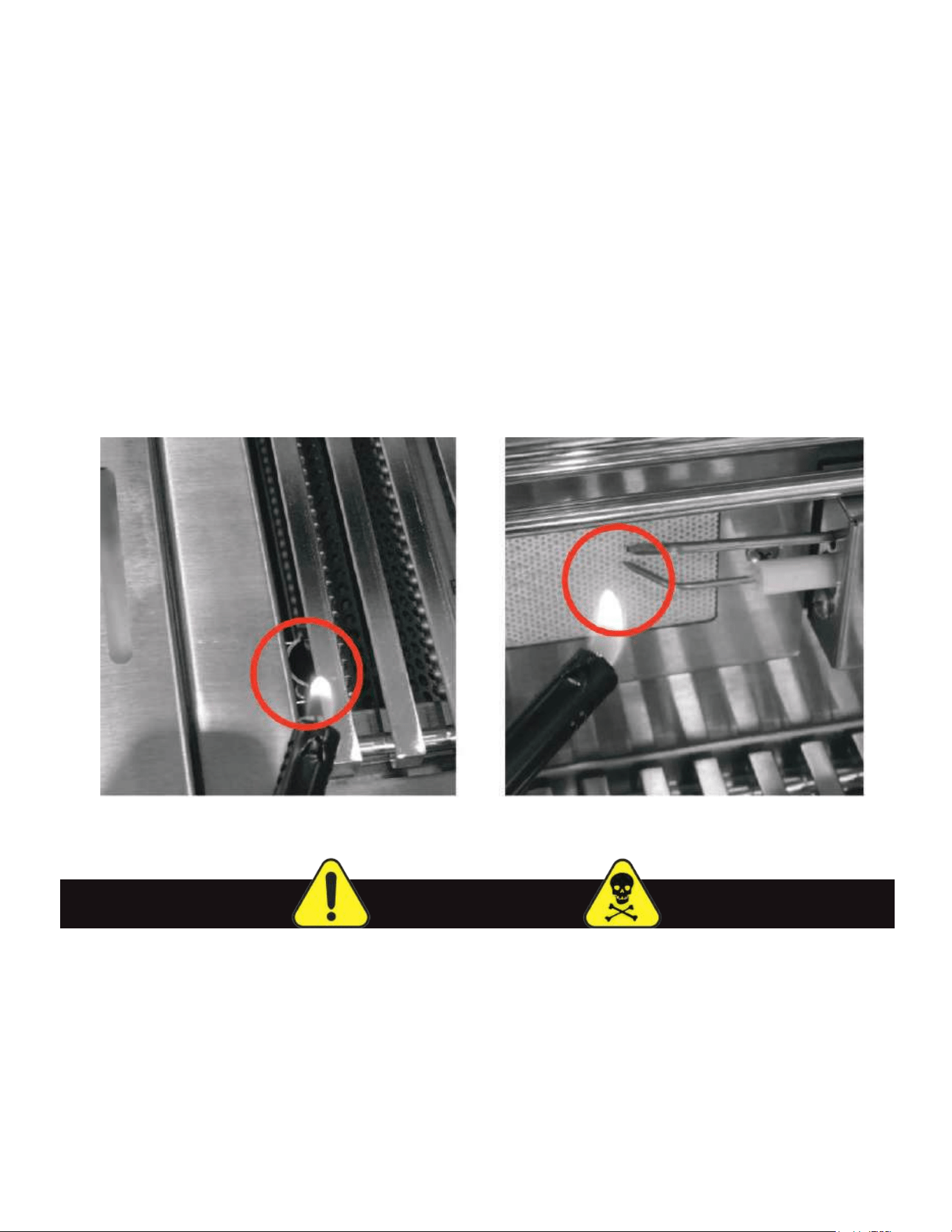
MANUALLY LIGHTING THE GRILL BURNERS:
1. Open the hood and wait five minutes to allow any accumulated gas to dissipate.
2. Keep your face as far away from the burners as possible.
3. Light and insert a long-stem match, holding it near the Lighting Tube on the left side to light the main
burner or the right hand side of the rear burner.
When lighting the rear burner continue to hold the flame next to the thermocouple until the burner is glowing.
4. Slowly rotate the burner knob for the burner you are lighting counter-clockwise to the high position.
5 If the burner does not light after five seconds, turn the control knobs to
the OFF position and wait five
minutes until the gas clears before attempting to re-light.
6.
If the burner does not light after several attempts, immediately close all gas valves and consult an
authorized
authorized service technician.
7.
To shut off the burners, rotate the knob and turn to OFF.
8. It is normal to hear a popping sound when the burners are turned off.
MANUALLY LIGHTING MAIN BURNER MANUALLY LIGHTING REAR BURNER
31
TEMPERATURE SETTINGS
HIGH Setting - Use this setting only for fast warm-up, for searing steaks and chops, and for burning food residue
from the cooking grates when done.
MEDIUM Setting - Use this setting for most grilling, roasting or baking, and for cooking hamburgers and vegetables.
LOW Setting - Use this setting for smoking, rotisserie cooking, and when cooking very lean cuts such as fish.
COOK FOOD TO PROPER TEMPERATURES
Cooking food safely requires that you raise the internal temperature of the meat high enough and for a long
enough period of time to kill any food-borne bacteria that may cause illnesses. Color is not the best indicator
that food is safe to eat. Use a high-quality probe thermometer to be sure your food is properly cooked. Place
the tip of an instant-read thermometer into the center of the thickest part of the food but at least 1/2 inch deep.
Read the temperature after about 10 seconds. Follow the temperature guidelines for the type of food you are
cooking. The following guidelines are from the U.S. Food and Drug Administration Center for Food.
GRILLING TIPS
COOK TO INTERNAL TEMP
Meat And Poultry
Fresh Beef - Medium Rare 145°F 160°F 170°F
Ground Turkey, Chicken 165°F
Ground Veal, Beef, Lamb, Pork
145°F with 3 minutes of rest and then turn
Fresh Pork - Medium 160°F 170°F
Chicken - Whole 165°F
Turkey - Whole 165°F
Poultry Breasts, Roast 165°F
Poultry Thighs, Wings 165°F
Stuffing (Cooked Alone Or In Bird)
165°F
Duck And Goose 180°F
Fresh Veal - Medium Rare 160°F
Fresh Lamb - Medium Rare 160°F 170°F
Ham - Fresh (Raw) 145°F 160°F 170°F
Ham - Pre-Cooked (Reheat) 140°F
SEAFOOD
Fish
Cook until flesh turns opaque and flakes easily with a fork.
Shrimp, Lobster, Crab
Cook until shells turn red and flesh becomes pearly opaque.
Scallops Should turn milky white or opaque and firm
Clams, Mussels, Oysters
145°F
Medium
Medium Rare
Well Done
Cook until shells open.
*The above temperature settings are a guide, the temperatures may vary due to wind and outside
ambient temperatures
32
DIRECT COOKING
Direct cooking involves placing food on the grates over direct heat. Use this method for foods that take less
than 20 minutes to cook or use it to sear larger items before or after indirect cooking. Place the food to be
cooked directly on the preheated grates above firing burners and leave until they no longer stick. Turning too
soon and too often are the most common grilling mistakes. Use a meat thermometer to gauge when they are
done and remove items one degree below your desired temperature, will continue to rise slightly as they rest
before carving and consuming.
INDIRECT COOKING
The indirect cooking method is a popular alternative to direct heat grilling. Indirect cooking uses heat from
adjacent burners to cook food and, in many cases, this reduces the potential to overcook or overly brown food.
The most common uses are for items that benefit from slower cooking such as breads or thicker cuts of
chicken or roasts. Indirect cooking involves placing the food on grates above burners that are off and closing
the grill hood to create an oven effect. Items you usually oven-roast can be grilled to perfection using indirect
heating. Preheat the burners surrounding the food to be cooked. Place a basting pan below the grates directly
on the flame tamers under the food containing water or marinade to prevent the natural juices from burning
or evaporating. Indirect cooking can also be achieved using the second rack while direct cooking.
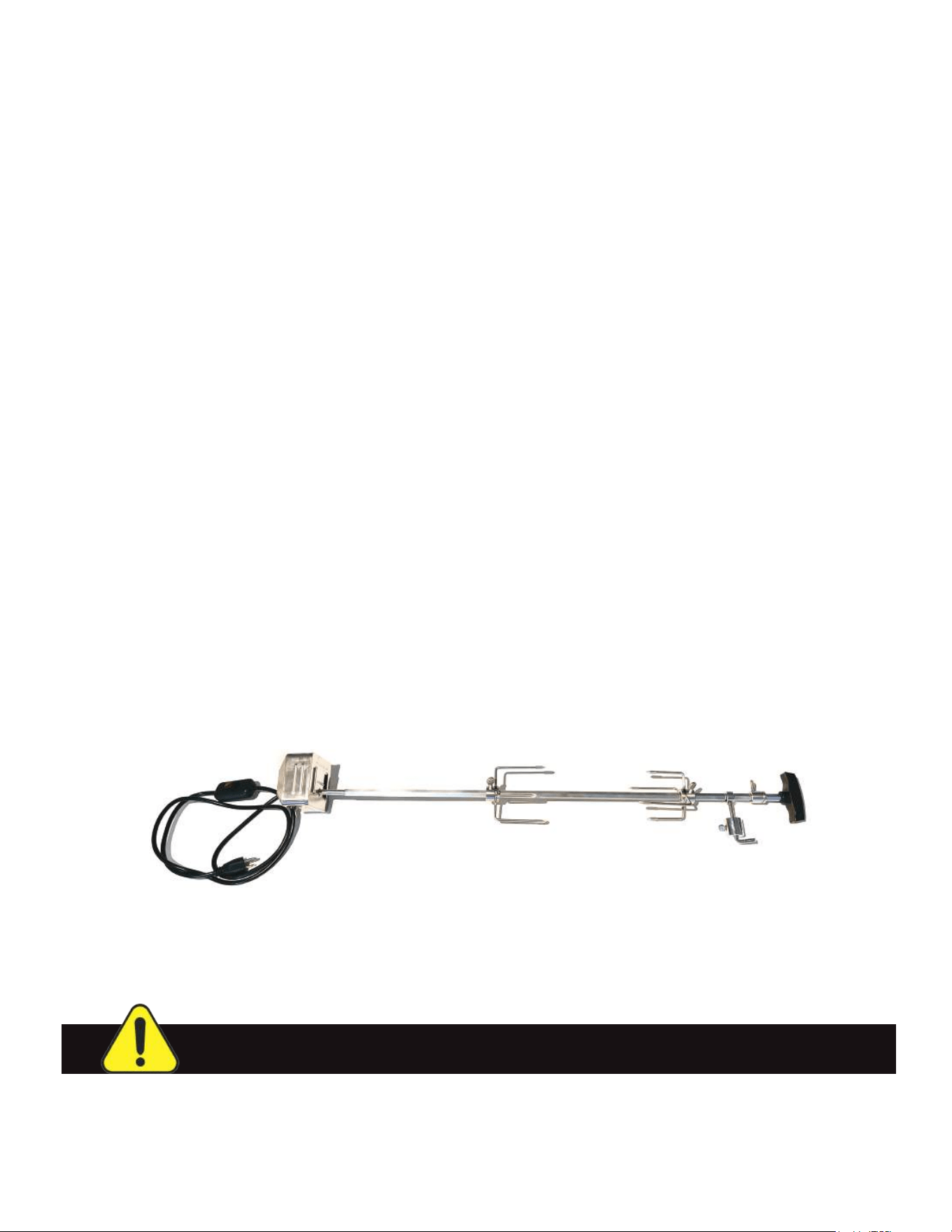
ROTISSERIE COOKING
Rotisserie is primarily used to slow cook large pieces of meat and poultry. Constant turning provides a self-
basting action, making food cooked on a rotisserie exceptionally moist and juicy. Rotisserie cooking generally
requires 1 ½ to 4½ hrs to cook depending on the size and type of meat being cooked. You can have rotisserie
cooking with indirect heat or with the rear infrared rotisserie burner. The meat should be centered and balanced
as evenly as possible on the spit rod to avoid overworking the rotisserie motor. Since indirect heat is often
used cooking on a rotisserie, a basting drip pan is advisable to prevent excessive flare-ups. Generally, the
cooking grates are removed to allow for greater swing of the rotisserie.
Your XO XLT grill is equipped with a rear infrared burner. Optional rotisserie kits are available for purchase
separately.
GRILLING METHODS
Use XOGROTIS32XLT for grill model XOGRILL32XLT2
Use XOGROTIS40XLT for grill model XOGRILL40XLT2
CAUTION: Remove secondary rack to prevent interference with the turning spit.
33
CLEANING AND MAINTENANCE
GENERAL GRILL CLEANING AND MAINTENANCE
Proper care and maintenance will keep your grill in top operating condition and prolong its life. Follow these
cleaning procedures on a timely basis and your grill will stay clean and operate with minimal effort.
CLEANING THE COOKING GRATES
Before initial use, and periodically thereafter, wash your Cooking Grids in a mild soap and warm water solution.
Use a wash cloth or vegetable brush to scrub them clean. After washing and before cooking, apply a light
coating of a high temperature cooking oil like canola to the grate surface.
CLEANING THE FLAME TAMERS
Periodically wash the Flame Tamers in soap and warm water using a vegetable brush to remove
stubborn burnt-on cooking residue. Dry the Flame Tamers thoroughly before you reinstall them.
CLEANING THE DRIP TRAY
To reduce the chance of fire, the drip tray should be visually inspected before each grill use. Remove
any grease and wash drip tray with a mild soap and warm water solution.
CLEANING INSIDE THE GRILL HOOD
Grease can build up on the inside of the hood over time and can drip outside the grill when opened.
Visually inspect the inside of the hood before each use. Remove any grease and wash with a mild soap
and warm water solution.
ROUTINE CLEANING OF THE GRILL INTERIOR
Burning-off excess food after every cookout will keep it ready for instant use. However, at least every 6 months
you must give the entire grill a thorough cleaning to minimize risk of grease fires and keep your grill in top shape.
FOLLOW THESE STEPS:
1. Turn all control knobs off and turn off the gas supply (LP or Natural Gas)
2. Remove and clean the grates, flame tamers, warming rack, zone dividers and burners.
3. Scrape out and brush debris from the inside and bottom of the fire box. Then wash the interior with a fiber
pad or nylon brush and a mild soap and warm water solution - rinse thoroughly and allow to dry.
4. Check all orifices for any obstructions.
5. Replace the burners, ensuring they are correctly centered on and overlapping each orifice.
6. Replace the flame tamers, zone dividers, warming rack and grates
7. Brush all vents, whether in a cart or built-in installation, free of any dirt or debris.
8. Reconnect the gas, leak test, ignite the burners and check the flame for correct operation.
CAUTION: MAKE CERTAIN THE GRILL IS OFF AND COMPLETELY COOL BEFORE PROCEEDING.
34

CARING FOR STAINLESS STEEL
Common conditions that cause the corrosion or discoloration of stainless steel:
1. Oxidation - Here are a few steps to bring your stainless appliances back to “like new” condition. Apply clean
water with a cleaning sponge and rub gently in the direction of the grain. If the mark won’t shift, it may be
necessary to use a stainless steel cleaner. Apply the cleaner and rub gently. After cleaning it is important to
rinse the stainless steel with clean fresh water and buff with a soft coth, always rubbing with the grain. Rubbing
across the grain can damage the finish and the stainless will lose its shine.
2. Chloride containing cleansers - this includes bleach and any cleaners containing bleach.
3. Muriatic acid (hydrochloric acid) - commonly used to clean up after tile/concrete installation.
4. Concentrated soap residue - chemical additives will cause discoloration / some dried soaps resemble rust.
5. Water with high iron content - can leave a rusty residue, especially if allowed to drip continuously.
6. Contact with iron materials - such as steel wool, iron residue from installation or cleaning of other steel
products.
7. Don’t allow trapped moisture between the product and cover - rubber mats, metal cans or cleaning products
ca
n also trap moisture. Allow cabinets to completely dry before covering.
8. Salts - contain chlorides
9. Extreme Heat by Flame
10. Acids - Do not permit liquids like citrus or tomato juice to remain on stainless steel surfaces. Wash regularly
with clean fresh water, mild detergent and a microfiber cloth. After washing rinse with clean water and wipe the
surface dry with a microfiber cloth. Be certain to go with the grain on brushed stainless steel. Generally you
should wash your stainless steel every three months. In those areas where the grill is exposed to high salt
concentrations such as coastal regions or chlorine near swimming pools, your stainless should be washed
at least every two weeks. Failure to maintain the finish in such environments will lead to tea staining and
corrosion. A thin coating of protectant on the surface is highly recommended in such cases.
11. Avoid all abrasive cleaners, steel wool or abrasive cloths as they will scratch the surface.
CARING FOR STAINLESS STEEL
Common conditions that cause the corrosion or discoloration of stainless steel:
1. Oxidation - Here are a few steps to bring your stainle
ss appliances back to “like new” condition. Apply clean
water with a cleaning sponge and rub gently in the direction of the grain. If the mark won’t shift, it may be
necessary to use a stainless steel cleaner. Apply the cleaner and rub gently. After cleaning it is important to
rinse the stainless steel with clean fresh water and buff with a soft coth, always rubbing with the grain. Rubbing
across the grain can damage the finish and the stainless will lose its shine.
2. Chloride containing cleansers - this includes bleach and any cleaners containing bleach.
3. Muriatic acid (hydrochloric acid) - commonly used to clean up after tile/concrete installation.
4. Concentrated soap residue - chemical additives will cause discoloration / some dried soaps resemble rust.
5. Water with high iron content - can leave a rusty residue, especially if allowed to drip continuously.
6. Contact with iron materials - such as steel wool, iron residue from installation or cleaning of other steel
products.
7. Don’t allow trapped moisture between the product and cover - rubber mats, metal cans or cleaning products
can also trap moisture. Allow cabinets to completely dry before covering.
8. Salts - contain chlorides
9. Extreme Heat by Flame
10. Acids - Do not permit
liquids like citrus or tomato juice to remain on stainless steel surfaces. Wash regularly
with clean fresh water, mild detergent and a microfiber cloth. After washing rinse with clean water and wipe the
surface dry with a microfiber cloth. Be certain to go with the grain on brushed stainless steel. Generally you
should wash your stainless steel every three months. In those areas where the grill is exposed to high salt
concentrations such as coastal regions or chlorine near swimming pools, your stainless should be washed
at least every two weeks. Failure to maintain the finish in such environments will lead to tea staining and
corrosion. A thin coating of protectant on the surface is highly recommended in such cases.
11. Avoid all abrasive cleaners, steel wool or abrasive cloths as they will scratch the surface.
CLEANING AND MAINTENANCE
35
CLEANING AND MAINTENANCE | BURNERS
WARNING
CAUTION
Before removing the burners ensure the gas is shut off and the knobs are in the “OFF” position. Make certain
the grill has cooled before proceeding.
TO REMOVE BURNERS:
Begin by removing all the grates, flame tamers and zone dividers. Make certain that any cotter pins or tie downs
which hold the burner in place during shipping have been removed. Grasp the burner, tilt and lift up the far end
of the burner while pushing it toward the back of the grill. The burner head will come off the brass orifice at the
front. Carefully remove making certain not to upset the air shutter position.
BURNER CLEANING:
To maximize grill performance, clean the exterior of the burner with a wire brush. Clear stubborn scale with a
metal scraper. Clear any clogged ports with a straightened paper clip. Never use a wooden toothpick as it may
break off and clog the port. Shake out any debris through the air shutter. Use a flashlight to inspect the burner
inlet to ensure it is not blocked. If obstructions can be seen, use a bent metal wire coat hanger to clear them.
BETTER AIR ADJUSTMENT:
Each grill burner is tested and adjusted at the factory prior to shipping, however, variations in the local gas supp
ly
or a conversion from one gas to another may make it necessary to adjust the burners. The flames of the grill
burners should be visually checked, adjusting the air shutter by opening the air shutter and slowly closing it until
the flame starts to yellow. STOP, and turn back 1/16", and tighten the screw. The flame should be blue with
yellow tips when adjusted correctly.
IF YOU ARE UNSURE OF HOW TO PROPERLY MAKE THESE ADJUSTMENTS CALL FOR SERVICE.
In reinstalling the burners, it is critical to center every burner on its orifice. If this is not done properly
there is a possibility of fire and/or explosion.
For safe operation, make sure the Orifices are centered inside the Burner Tubes before using your grill.
See figure. If the Orifice is not inside the Burner Tube, lighting the Burner may cause explosion and/or
fire resulting in serious bodily injury and/or property damage.
Please Note that the air mixture for LP gas and NG is
differen
t. Your gas grill will come preset for your gas type.
If you find that you are not getting the best flame the air
shutter can be adjusted to improve the oxygen/gas mix.
I you are unsure of how to perform this adjustment -
STOP and call for service.
Gas Valve
Assembly
Orifice
Burner Tube
Orifice
36
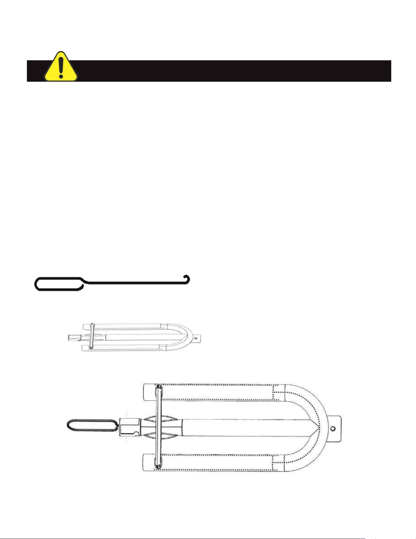
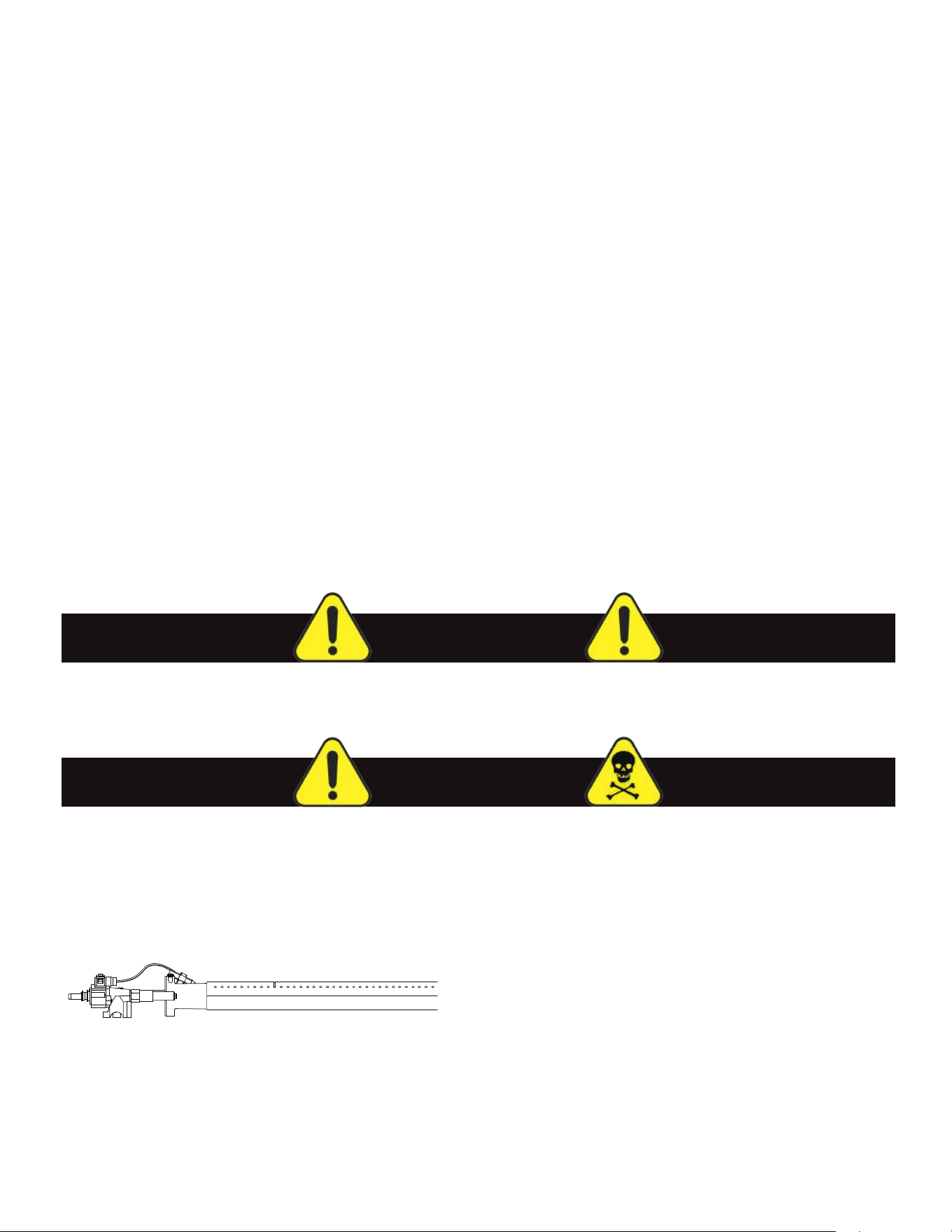
Spiders and small insects can spin webs and nest in the grill burner venturi which can lead to a gas flow
obstruction resulting in a fire in and around the burner tubes. This type of "FLASHBACK FIRE" can cause
serious grill damage and create an unsafe operating condition for the user.
To reduce the chance of FLASHBACK FIRE you must inspect and clean the venturi at least twice a year in
summer and fall, whenever spiders are active in your area, or if your grill has not been used for an extended
period of time.
Remove the pin from the rear of each burner tube using needle nose pliers. Carefully lift each burner up and
away from the gas valve orifice. Check the burner venturi tubes for insects and nests. Clean as shown below.
A clogged tube can lead to a fire beneath the grill.
FOR CLEANING, REFER TO METHODS 1-3 BELOW:
METHOD 1: Bend a stiff wire or wire coat hanger into a small hook as shown and run the hook through the
Burner Tube and inside the Burner several times to remove debris.
METHOD 2: Use a bottle brush with a flexible handle and run the brush through the Burner Tube and inside
the Burner several times to remove any debris.
METHOD 3: Use an air hose to force air through each Burner Tube. The forced air should pass debris or
obstructions through the Burner and out the Ports. This method should only be performed by a certified and
qualified BBQ technician.
CLEANING THE BURNERS - CONTINUED
WARNING: READ AND FOLLOW ALL SAFETY PRECAUTIONS
For safe operation ensure the Gas Valve Assembly
Orifice is inside the Burner Tube before using your
grill. (See figure above). If the Orifice is not inside
the Burner Tube, lighting the Burner may cause
an explosion and/or fire resulting in serious bodily
injury and/or property damage.
Burner Holes
Gas Venturi
To Clean Burner Tube,
Insert Hook Here
37
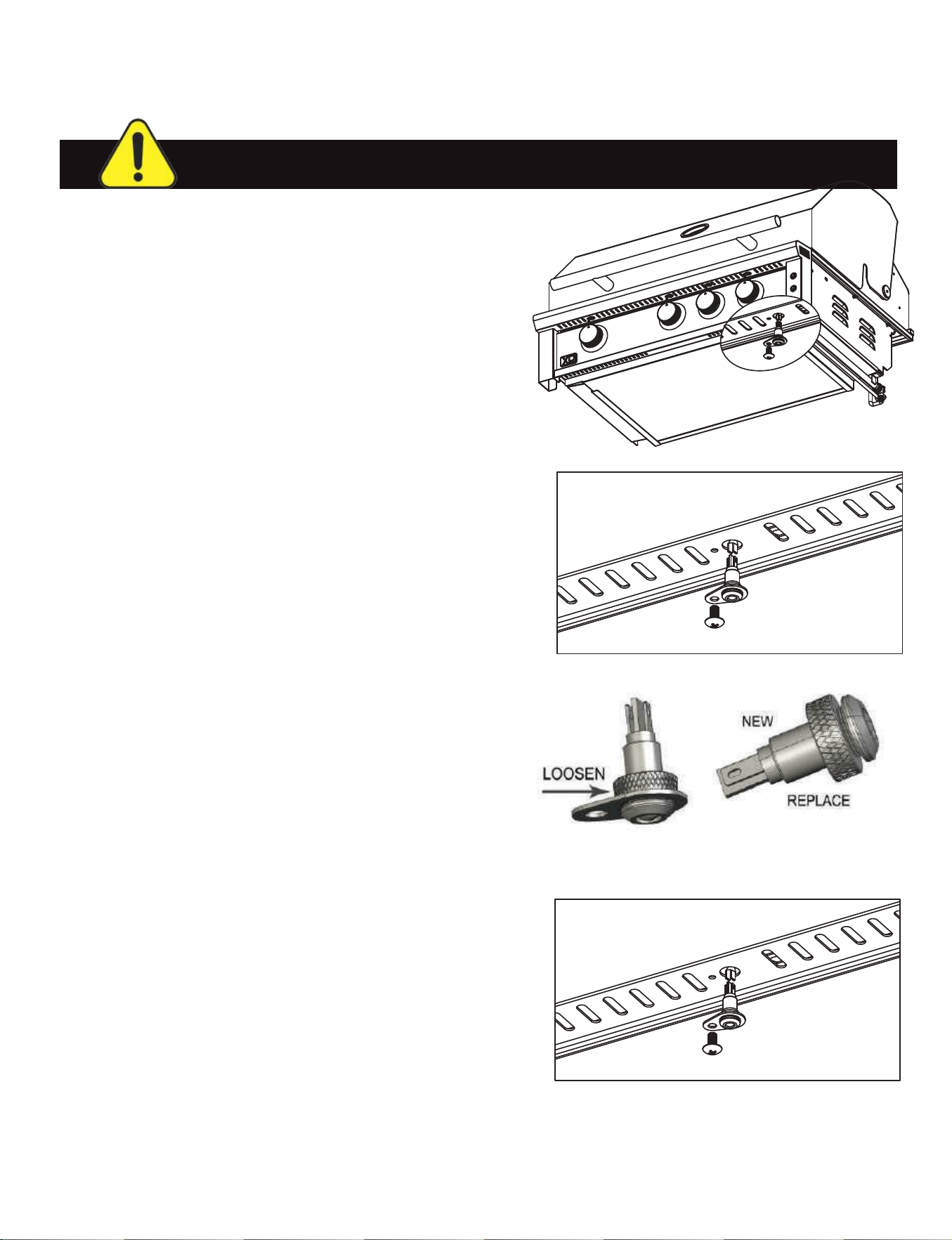
STEP 1.
Using a Phillips head screwdriver, remove the screws
holding the LED Bulb fixture in place.
STEP 2.
Pull down to remove the LED Bulb fixture and disconnect
the wire plug.
STEP 3.
Remove the bracket by unscrewing the lock nut on the bulb
Remove the lock nut from the new bulb and use it to install
the bracket.
STEP 4.
Connect the new bulb fixture to the wiring harness, feed it
back into the opening and replace the screw removed in
Step 1 to hold it in place.
REPLACING LED BULBS
NOTE: DISCONNECT THE GRILL AT THE POWER SOURCE BEFORE REPLACING BULBS.
38
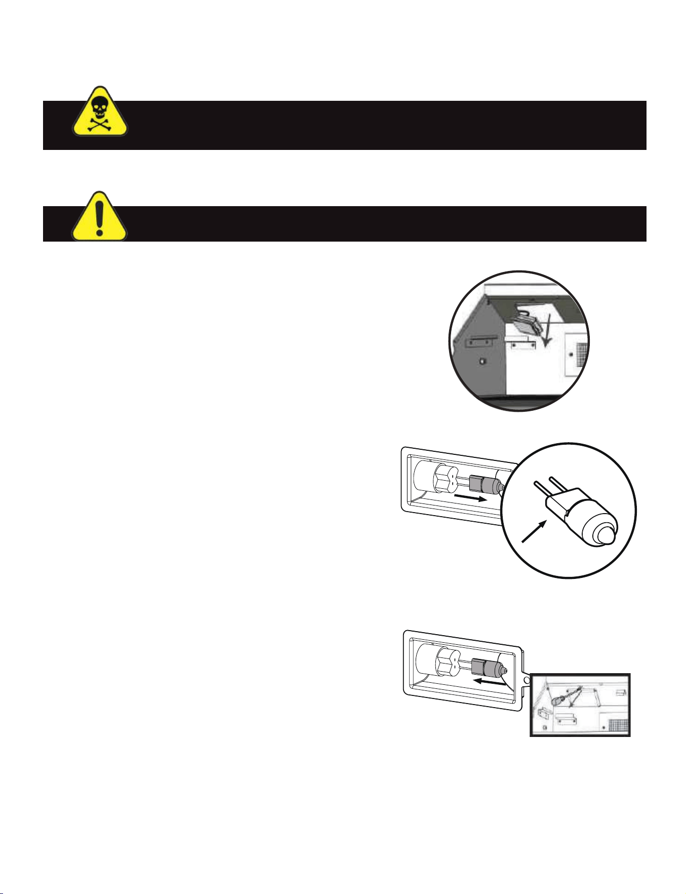
STEP 1.
Unplug the grill from the power supply. Using a #2 Phillips
screwdriver. Remove the screw holding the light housing.
STEP 2.
Carefully remove the housing from grill. DO NOT PULL
HARD - It is attached by electrical wires. Remove the
clip holding the light cover to the housing.
STEP 3.
With the light cover removed pull the halogen bulb out
sideways from light socket. CAREFUL - the bulbs are
fragile and can break, grip with your fingers only by the
sides.
STEP 4.
Do not touch the new bulb with your bare skin.
Holding it wrapped in cloth, replace bulb by pus
hing
it straight into light socket. Re-attach light cover, and
reinstall the housing by repeating steps 2. and 3. in
reverse order.
REPLACING HALOGEN BULBS
DANGER: HALOGEN BULBS GET EXTREMELY HOT DURING USE.
MAKE CERTAIN THEY ARE COMPLETELY COOL BEFORE ATTEMPTING A CHANGE OUT.
NOTE: DISCONNECT THE GRILL AT THE POWER SOURCE BEFORE REPLACING BULBS.
10w/12V
REMEMBER - AVOID TOUCHING THE NEW BULB WITH BARE SKIN
Oil from your skin will reduce bulb life. Avoid touching the bulb with your bare hands.
Hold the new bulb with a clean lint free cloth. Wipe the bulb clean after handling.
39

TROUBLESHOOTING
Often minor issues can be be resolved quickly and easily by the homeowner.
This section is not intended as a replacement for qualified, professional service but rather as a general guide
to determine if a service technician is needed. If you are unsure of any issue or have a question regarding
your gas gril, do not hesitate to contact our service team. They are here to help you.
XO Service can be reached at 973-403-8900 or by emailing service@easternmarketing.com
BEFORE CALLING SERVICE - SOME COMMON QUESTIONS & FIXES:
1. Is there fuel supplied to the grill?
2. Is the main shut-off valve open?
3. Are you using the correct type of fuel for the grill? (Propane or Natural Gas)
4. Is the grill plugged in to a live, grounded GFCI electric circuit?
5. Are all burners out or just one?
6. Can you light the burner with a match?
ISSUE
Low Heat or Low Flame
(with the control knob set on High)
Uneven heating
Yellow flame
(accompanied by smell of gas)
POSSIBLE CAUSE (+REMEDY)
For built-In / undersized supply line
(Consult code - recommended 3/4” ID pipe minimum)
For freestanding / kinked or restricted supply hose
(Reposition gas supply hose to remove restriction)
Dirty or clogged orifice or venturi
(see section on Cleaning Burners)
Flame tamers / built up debris and residue
(Preheat for 10 minutes and see if it burns off)
(Perform cleaning on flame tamers)
Drip pan / requires cleaning
(Clean drip pan as per instructions)
Burners fouled or ports plugged
(Clean burners as per instructions)
Insect blockage in burner venturi
(Thorough burner cleaning as per instructions)
Open or improperly set air shuttle
(Call for service)
40

TROUBLESHOOTING - CONTINUED
ISSUE
Burner not lighting with igniter
but will light with match
Humming Regulator Noise
Burners not cross lighting
Infrared burner will not light
Infrared burner Issues
(Flashes back | makes “Whoosh” noise |
Surface grows dim)
Control panel lights off
Burner goes out
Burner goes out on low setting
ISSUE
Burner not lighting with igniter
but will light with match
Humming Regulator Noise
Burners not cross lighting
Infrared burner will not light
Infrared burner Issues
(Flashes back | makes “Whoosh” noise |
Surface grows dim)
Control panel lights off
Burner goes out
Burner goes out on low setting
POSSIBLE CAUSE (+REMEDY)
Dirty Electrode
(Clean electrode with Isopropol Alcohol & Cloth)
Wet Electrode
(Wipe dry with cloth)
Blocked or damaged valve
(Call for Service)
Common internal vibration
(No service required)
Debris / Grease blocking cross lighting channels
(Clean crosslighting channels)
Burner ports near cross lighting channels blocked
(Clear blocked burner ports with wire)
Knob must be held in for30 seconds after ignition
(attempt to relight with long match holding knob in)
Ceramic ports are clogged with debris
(Turn off for 2 min - restart and run on high 5 min
or until glowing red evenly)
Cracked ceramic
(Call for service)
No power
(Check transformer plugged in & GFCI has not tripped)
Faulty transformer
(Check for 12v output - replace transformer)
Faulty push button switch
(Test switch - change as necessary)
Grill location - Wind Issue
(Relocate grill or install wind break)
Burner misaligned
(Check to ensure burner is properly seated / Call for service)
Supply hose is pinched or kinked
(Reposition supply hose)
Dirty or clogged orifice or venturi
(see section on
Cleaning Burners)
41
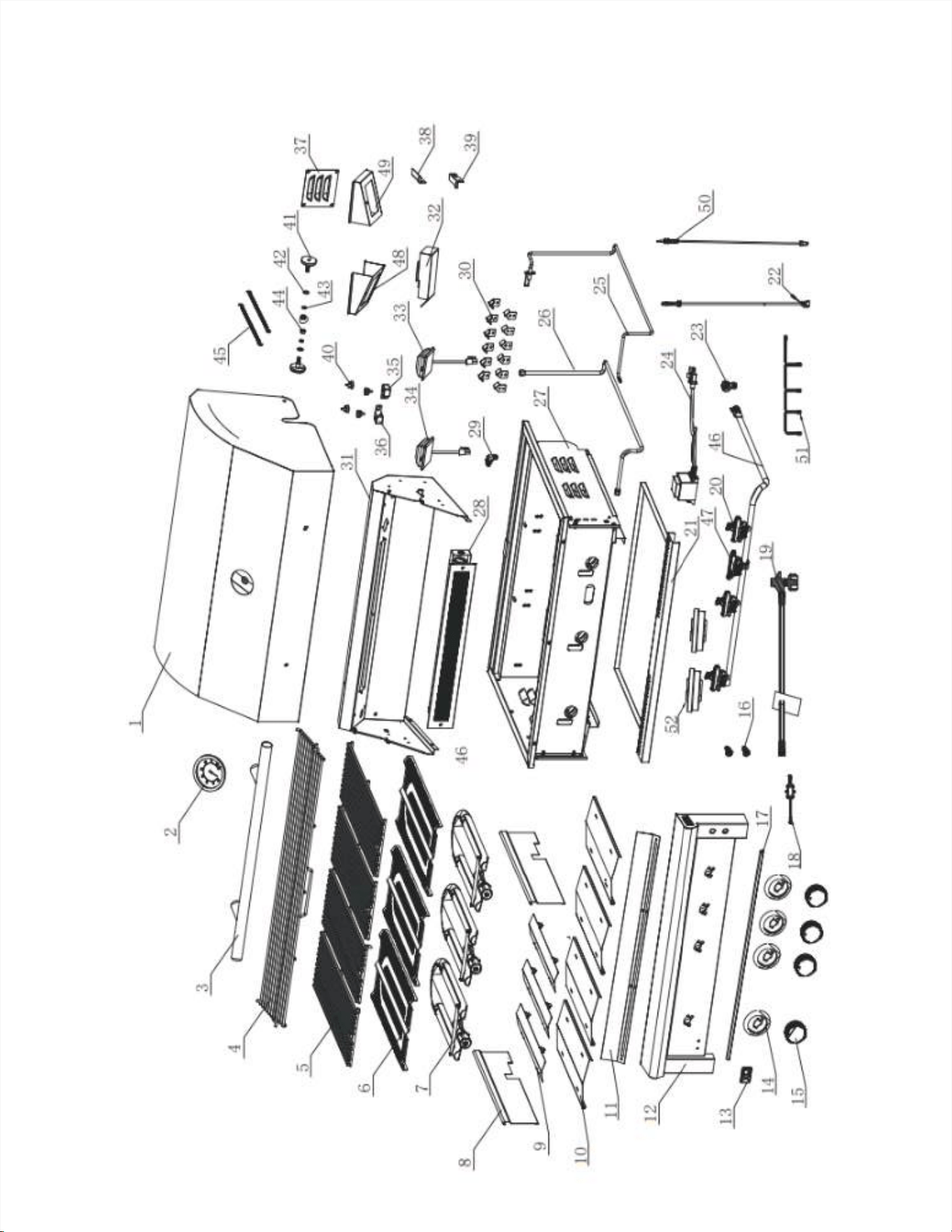
XOGRILL32XLT2 PARTS LIST
WARNING: READ AND FOLLOW ALL SAFETY PRECAUTIONS
42

XOGRILL32XLT2 PARTS LIST
WARNING: READ AND FOLLOW ALL SAFETY PRECAUTIONS
Item # Description Part # Quantity
1 Hood (32XLT) XOPG365 1
2 Thermometer XOPG302 1
3 Handle (32XLT) XOPG303 1
4 Warming Rack (32XLT) XOPG366 1
5 Grate XOPG307 4
6 Flame Tamer (32XLT) XOPG308 3
7 Main Burner XOPG310 3
8 Heat Zone Separator XOPG311 2
9 Upper Drip Pan Baffle XOPG312 3
10 Lower Drip Pan Baffle XOPG313 4
11 LED Heat Shield (32XLT) XOPG367 1
12 Control Panel (32XLT) XOPG368 1
13 Logo XOPG317 1
14 Bezel XOPG369 4
15 Knob XOPG319 4
16 Light Switch XOPG320 2
17 LED Light XOPG370 1
18 BALLAST RESISTOR XOPG371 1
19 Regulator w/Hose XOPG128 1
19 Regulator XOPG127 1
20 Main Valve XOPG326 3
21 Drip Tray (32XLT) XOPG328 1
22 Wire Harness XOPG330 1
23 LP Elbow XOPG126 1
23 NG Elbow (1/2" x 1/2") XOPG129 1
24 Transformer XOPG333 1
25 Ignition Needle XOPG334 1
26 Flex Line XOPG335 1
27 Firebox (32XLT) XOPG336 1
28 Rear Burner (32XLT) XOPG338 1
29 Rear Burner Orifice LP (1.1) XOPG340 1
29 Rear Burner Orifice NG (1.5) XOPG341 1
30 Flame Tamer Support XOPG342 12
31 Fire Box Back Wall (32XLT) XOPG372 1
32 Ignition Cover XOPG373 1
33 Right Hood Lamp XOPG346 1
34 Left Hood Lamp XOPG345 1
35 Hood Support Right XOPG347 1
36 Hood Support Left XOPG348 1
37 Louver Cover XOPG349 1
38 Rack Left Support (XLT2) XOPG374 1
Item # Description Part # Quantity
39 Rack Right Support (XLT2) XOPG375 1
40 Rubber Bumper XOPG352 4
41 Hood Spin Axis XOPG353 2
42 M6 Flat Washer XOPG354 2
43 M6 Spring Washer XOPG355 2
44 M6 Lock Nut XOPG356 2
45 Spring XOPG357 2
46 Manifold (32XLT) XOPG363 1
47 Rear Valve XOPG376 1
48 Left Lamp Cover (XLT2) XOPG377 1
49 Right Lamp Cover (XLT2) XOPG378 1
50 Thermocouple (XLT2) XOPG379 1
51 Bezel Wiring (32XLT2) XOPG380 1
52 Crossfire (XLT2) XOPG381 2
53 Main Orifice LP (1.18) XOPG358 3
54 Main Orifice NG (1.98) XOPG359 3
43
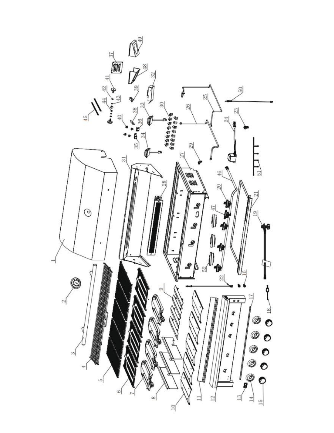
XOGRILL40XLT2 PARTS LIST
WARNING: READ AND FOLLOW ALL SAFETY PRECAUTIONS
44

XOGRILL40XLT2 PARTS LIST
WARNING: READ AND FOLLOW ALL SAFETY PRECAUTIONS
Item # Description Part # Quantity
1 Hood (40XLT2) XOPG382 1
2 Thermometer XOPG302 1
3 Handle (40XLT) XOPG304 1
4 Warming Rack (40XLT2) XOPG383 1
5 Grate XOPG307 5
6 Flame Tamer (40XLT) XOPG309 4
7 Main Burner XOPG310 4
8 Heat Zone Separator XOPG311 3
9 Upper Drip Pan Baffle XOPG312 4
10 Lower Drip Pan Baffle XOPG313 5
11 LED Heat Shield (40XLT2) XOPG384 1
12 Control Panel (40XLT2) XOPG385 1
13 Logo XOPG317 1
14 Bezel XOPG369 5
15 Knob XOPG319 5
16 Light Switch XOPG320 2
17 LED Light (40XLT) XOPG386 1
18 BALLAST RESISTOR XOPG371 1
19 Regulator w/Hose XOPG128 1
19 Regulator XOPG127 1
20 Main Valve XOPG326 4
21 Drip Tray (40XLT) XOPG329 1
22 Wire Harness XOPG330 1
23 LP Elbow XOPG126 1
23 NG Elbow (1/2" x 1/2") XOPG129 1
24 Transformer XOPG333 1
25 Ignition Needle XOPG334 1
26 Flex Line XOPG335 1
27 Firebox (40XLT) XOPG337 1
28 Rear Burner (40XLT) XOPG339 1
29 Rear Burner Orifice LP (1.1) XOPG340 1
29 Rear Burner Orifice NG (1.5) XOPG341 1
30 Flame Tamer Support XOPG342 16
31 Fire Box Back Wall (40XLT2) XOPG387 1
32 Ignition Cover XOPG373 1
33 Right Hood Lamp XOPG346 1
34 Left Hood Lamp XOPG345
1
35 Hood Support Right XOPG347
1
36 Hood Support Left XOPG348
1
37 Louver Cover XOPG349 1
38 Warming Rack Support Left XOPG374 1
Item # Description Part # Quantity
39 Warming Rack Support Right XOPG375 1
48 Left Lamp Cover (XLT2) XOPG377
1
40
Rubber Bumper XOPG352 4
49 Right Lamp Cover (XLT2) XOPG378
1
41 Hood Spin Axis XOPG353 2
50 Thermocouple (XLT2) XOPG379 1
42 M6 Flat Washer XOPG354 2
51 Bezel Wiring (40XLT2) XOPG388 1
43 M6 Spring Washer XOP
G355 2
52 Crossfire (XLT2) XOPG381 3
44 M6 Lock Nut XOPG356 2
53
Main Orifice LP (1.18) XOPG358 4
45 Spring XOPG357 2
54
Main Orifice NG (1.89) XOPG359 4
46 Manifold (40XLT) XOPG364
1
47 Rear Valve (XLT2) XOPG376
1
45
Parts Not Under Warranty can be ordered through XO directly.
Parts Under Warranty require a proof of purchase and can be ordered by contacting XO Appliance.
Proof of purchase is required for all warranty parts.
All parts listed in the Parts List have a Part Number.
When ordering parts, first obtain the Model and Serial Numbers from the name plate on your equipment.
Then determine the Part Number and the Description of each part from the following illustration and parts
list.
For your convenience, record that information here. When ordering be sure to give all this information.
Appliance Model Number
Appliance Serial Number
Part Number(s)
Type of Gas (Check One) Natural Gas (NG) Propane (LP)
Do not order bolts, screws, washers or nuts.
They are standard hardware items and can be purchased at any local hardware store.
Shipments contingent upon strikes, fires and all causes beyond our control.
Your XO Perfor,ance XLT Gas Grill is identified by model number, serial number, and gas type.
This information is provided on a product identification label located on the left side of the
grill and under
the grill’s drip tray.
convenience, complete this section for future reference when contacting XO Appliance.
ORDERING PARTS
CALL 973-403-8900
or email
46
Limited Lifetime Parts Warranty
Five Year Limited Parts Warranty
Two Year Limited Parts Warranty
One Year Limited Parts & Labor Warranty

48 XOGRILLXLTMAN25A
APPLIANCE
www.xoappliance.com