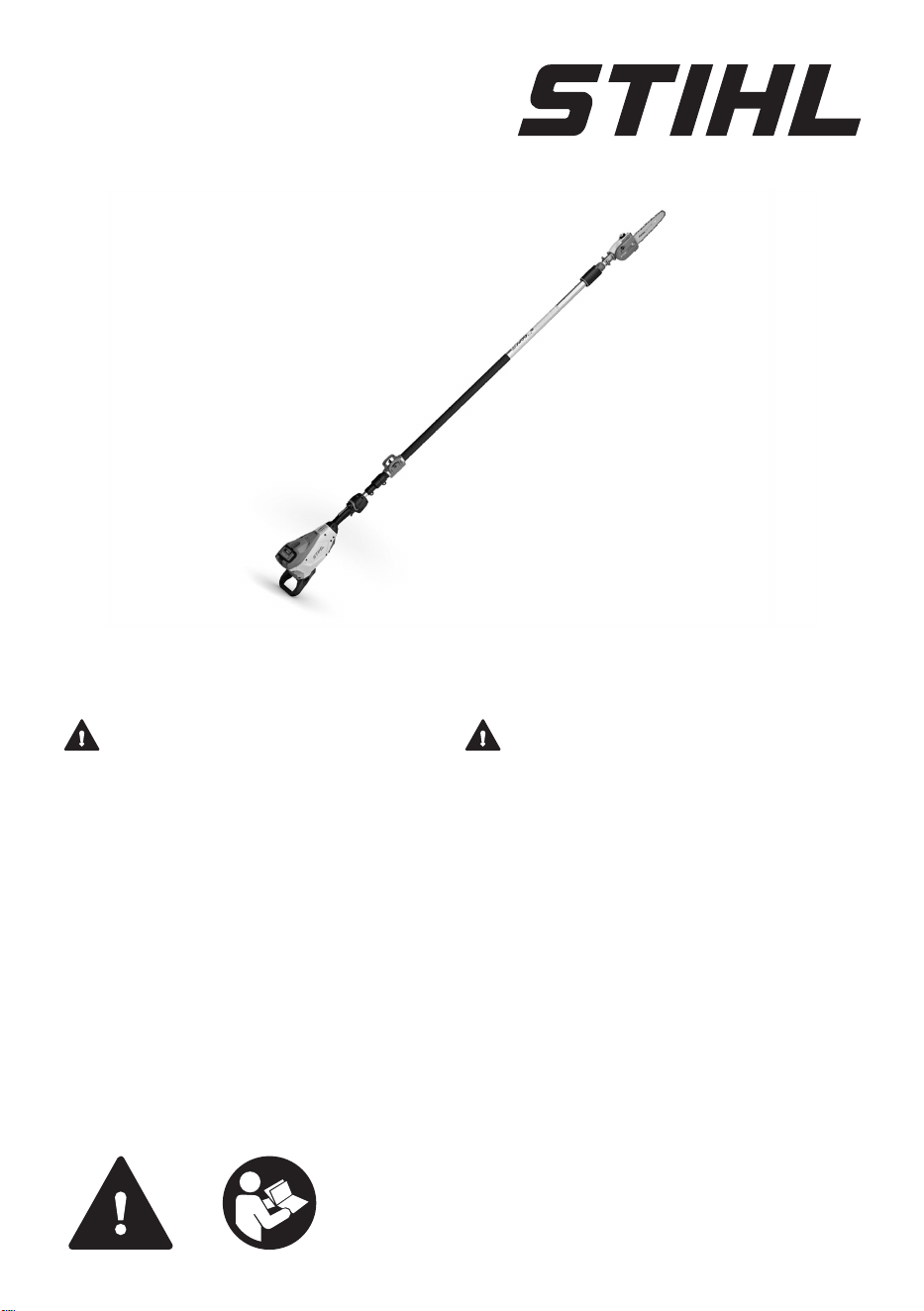
HTA 135
WARNING
Read Instruction Manual thoroughly before use and
follow all safety precautions – improper use can cause
serious or fatal injury.
ADVERTENCIA
Antes de usar la máquina lea y siga todas las precauciones
de seguridad dadas en el manual de instrucciones – el uso
incorrecto puede causar lesiones graves o mortales.
2 - 41 Instruction Manual
42 - 87 Manual de instrucciones
Contents
1 Introduction................................................. 2
2 Guide to Using this Manual.........................2
3 Main Parts...................................................3
4 Safety Symbols on the Products.................4
5 General Power Tool Safety Warnings.........5
6 IMPORTANT SAFETY INSTRUCTIONS....6
7 Kickback and Other Reactive Forces........14
8 Battery Safety........................................... 15
9 Maintenance, Repair and Storage............ 16
10 Before Starting Work.................................17
11 Charging the Battery................................. 17
12 LED Diagnostics and Acoustic Signals..... 19
13 Bluetooth® Radio Interface.......................20
14 STIHL AR Backpack Battery.....................20
15 Assembling the Pole Pruner..................... 21
16 Inserting and Removing the Battery..........26
17 Switching the Pole Pruner On and Off...... 26
18 Checking the Pole Pruner......................... 27
19 During Operation.......................................28
20 After Finishing Work..................................30
21 Transporting the Pole Pruner and Battery 30
22 Storing the Pole Pruner and Battery......... 31
23 Cleaning....................................................31
24 Inspection and Maintenance..................... 32
25 Troubleshooting Guide..............................36
26 Specifications............................................37
27 Combinations of Guide Bars and Saw
Chains.......................................................40
28 Approved Harness Combinations............. 40
29 Replacement Parts and Equipment.......... 40
30 Disposal.................................................... 40
31 Limited Warranty.......................................41
32 Trademarks...............................................41
33 Addresses................................................. 41
1 Introduction
Thank you for your purchase. The information
contained in this manual will help you receive
maximum performance and satisfaction from
your STIHL pole pruner and, if followed, reduce
the risk of injury from its use.
SAVE THIS MANUAL!
Because a pole pruner is a high-
speed wood-cutting tool with an
extended reach, special safety
precautions must be observed to
reduce the risk of personal injury.
Read this instruction manual thor‐
oughly before use and periodically
thereafter. Follow all safety pre‐
cautions. Careless or improper
use of the pole pruner can cause
serious or fatal injury.
Observe all applicable federal, state and local
safety regulations, standards and ordinances.
Do not lend or rent your pole pruner without this
instruction manual. Allow only persons who have
the proper training and fully understand the infor‐
mation in this manual to operate the pole pruner.
For further information, or if you do not under‐
stand any of the instructions in this manual,
please go to www.stihlusa.com or contact your
authorized STIHL servicing dealer.
2 Guide to Using this Manual
2.1 Signal Words
This manual contains safety information that
requires your special attention. Such information
is introduced with the following symbols and sig‐
nal words:
DANGER
■ Indicates a hazardous situation which, if not
avoided, will result in death or serious injury.
WARNING
■ Indicates a hazardous situation which, if not
avoided, could result in death or serious injury.
NOTICE
■ Indicates a risk of property damage, including
damage to the machine or its individual com‐
ponents.
2.2 Symbols in Text
The following symbol is included to assist you
with the use of the manual:
Refers to a designated chapter or sub-
chapter in this instruction manual.
English
2 0458-698-8621-B
© ANDREAS STIHL AG & Co. KG 2025
0458-698-8621-B. VA2.B25.
Printed on chlorine-free paper
Paper is recyclable.
Original Instruction Manual
0000009293_011_GB
3 Main Parts
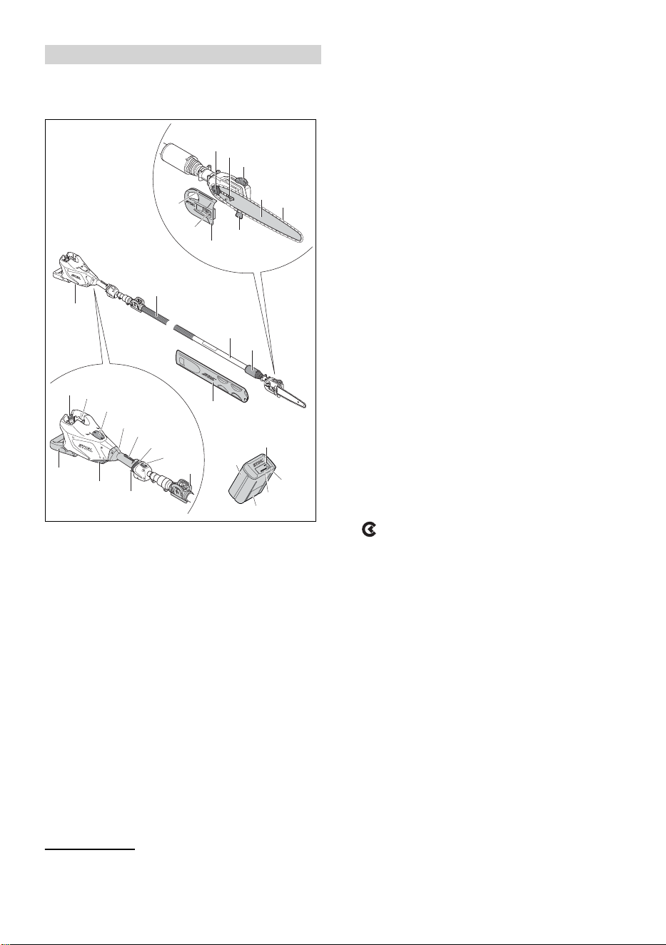
3.1 STIHL HTA 135 Pole Pruner
and Battery
0000097168_005
17
#
16
15
14
13
28
27
26
#
1
18
25
19
21
20
22
23
24
4
5
6
2
3
10
9
7
8
11
12
1 Front Handle
Handle for the operator's front hand.
2 Drive Tube
Pole pruner shaft.
3 Clamping Nut
For adjusting the length of the drive tube.
4 Chain Sprocket
Drives the saw chain.
5 Side Chain Tensioner
Permits precise adjustment of saw chain ten‐
sion.
6 Oil Filler Cap
For closing the oil tank.
7 Guide Bar
Supports and guides the saw chain.
8 Saw Chain
Toothed cutting tool consisting of cutters, tie
straps and drive links.
9 Hook
Helps hold the pole pruner steady against the
branch during cutting.
10 Chain Sprocket Cover
Covers the chain sprocket.
11 Nut
Tightens the chain sprocket cover.
12 Limbing Sight
Helps the operator position the bar and chain
for the cut.
13 Chain Scabbard
Covers the guide bar and saw chain to
reduce the risk of injury from inadvertent con‐
tact during transportation and storage.
14 Battery
Supplies electrical power to the motor.
15 Battery LEDs
Indicate the battery's state of charge and dis‐
play error messages regarding potential mal‐
functions in the battery or power tool.
16 Push Button
Activates the battery's LEDs. Activates and
deactivates the Bluetooth® interface (if appli‐
cable).
17
"BLUETOOTH
®
" LED (only for batteries with
)
Indicates whether the Bluetooth® interface is
enabled or disabled.
18 Locking Levers
Secure the battery in the battery compart‐
ment.
19 Battery Compartment
Holds the battery.
20
Mounting Recess Cover
1
Covers the mounting area for a Smart Con‐
nector 2 A.
21 Control Handle
Handle for the operator's rear hand.
22 Trigger Switch Lockout
Must be depressed to allow activation of the
trigger switch.
23 Retaining Latch
For switching the pole pruner on.
1
Remove the mounting recess cover only to install a Smart Connector 2 A. Store it safely for later rein‐
stallation. Always use the power tool with the mounting recess cover in place or with the Smart Con‐
nector 2 A mounted.
3 Main Parts English
0458-698-8621-B 3
24 LED
Indicate the unit's power level.
25 Harness Clip
For connecting a harness to the pole pruner.
26 Trigger Switch
Activates the saw chain when depressed.
27 Air Filter
Filters the air drawn into the motor.
28 Machine Support
For resting the pole pruner on the ground.
# Rating Plate
Contains electrical information and the pro‐
duct's serial number.
4 Safety Symbols on the
Products
4.1 Pole Pruner
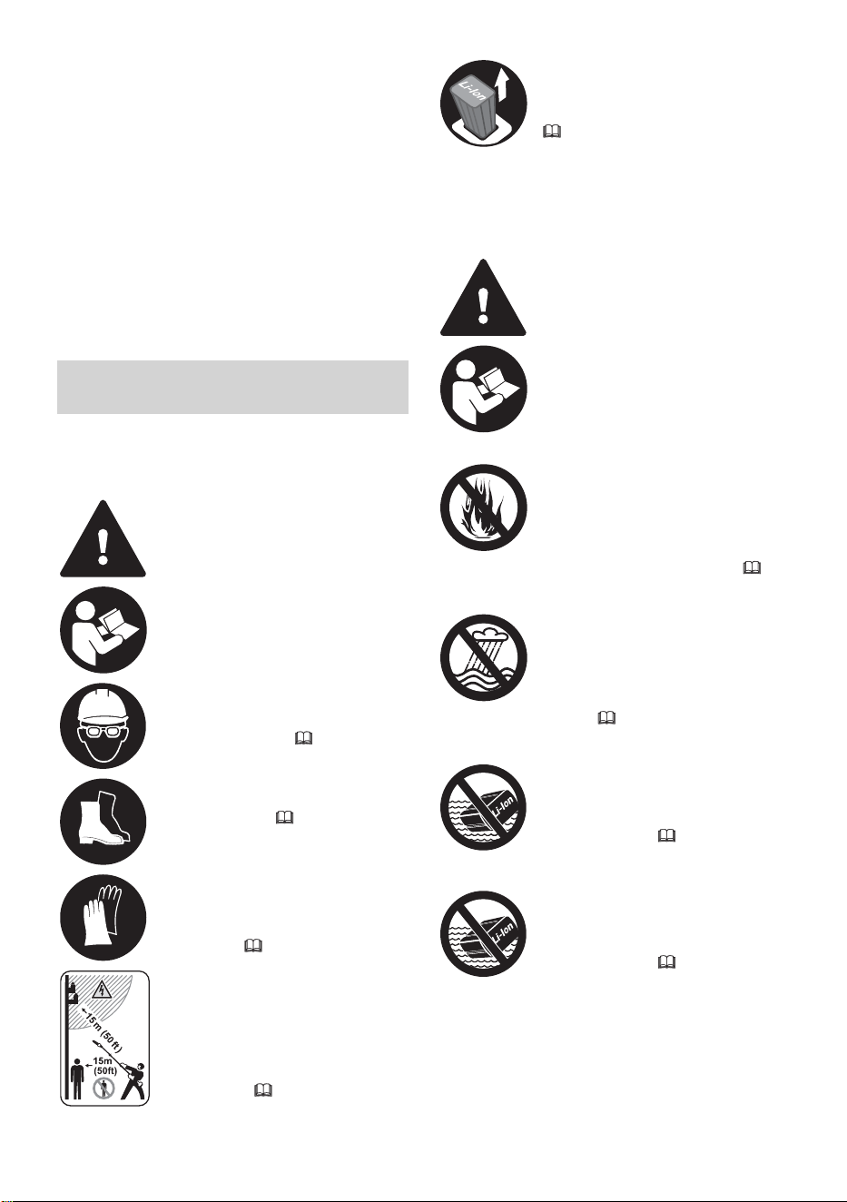
The following safety symbols are found on the
pole pruner.
To reduce the risk of injury, follow
the specified safety precautions.
Read and follow all safety precau‐
tions in the instruction manual.
Improper use can lead to serious
or fatal personal injury or property
damage.
To reduce the risk of eye and
head injury, always wear proper
eye protection and an approved
protective helmet, 6.3.
Wear sturdy boots with non-slip
soles. Steel-toed safety boots are
recommended, 6.3.
Always wear non-slip, heavy-duty
work gloves (e.g. made of leather
or other wear resistant material)
when handling the machine or
saw chain, 6.3.
To reduce the risk of personal
injury, keep bystanders at least
50 ft. (15 m) away and maintain a
clearance of at least 50 ft. (15 m)
between the pole pruner (includ‐
ing any branches it is contacting)
and any electrical line carrying
live current, 6.5.4.
To reduce the risk of injury or
property damage from unintended
activation, remove the battery any
time the pole pruner is not in use,
6.4.
4.2 Battery
The following safety symbols are found on the
AR series backpack battery and the AP series
battery:
To reduce the risk of injury, follow
the specified safety precautions.
Read and follow all safety precau‐
tions in the battery's instruction
manual and the manual for the
STIHL tool powered by this bat‐
tery. Improper use can lead to
serious or fatal personal injury or
property damage.
To reduce the risk of personal
injury or property damage from
fire, explosion or burns, including
chemical burns, do not disassem‐
ble, crush, drop, damage or heat
above 212 °F (100 °C). Never
expose to fire or incinerate, 8.
AR 1000, 2000, 3000 Backpack Batteries
To reduce the risk of personal
injury or property damage from a
short circuit, fire or explosion,
keep dry. Protect from rain, water,
liquids and damp conditions.
Never immerse in water or other
liquids, 8.
AR L Backpack Batteries
To reduce the risk of personal
injury or property damage from a
short circuit, fire or explosion,
keep dry. Never immerse in water
or other liquids, 8.
AP Series Batteries
To reduce the risk of personal
injury or property damage from a
short circuit, fire or explosion,
keep dry. Never immerse in water
or other liquids, 8.
Batteries sold separately.
English 4 Safety Symbols on the Products
4 0458-698-8621-B

5 General Power Tool Safety
Warnings
5.1 Introduction
This chapter contains the prescribed general
safety warnings and instructions for handheld,
motor-operated electric power tools. Additional
important warnings and instructions are provided
in subsequent chapters of this manual.
WARNING
■ Read all safety warnings and all instructions.
Failure to follow the warnings and instructions
may result in electric shock, fire and/or serious
injury.
■
Save all warnings and instructions for future
reference.
The term “power tool” in the warnings refers to
your mains-operated (corded) power tool or bat‐
tery-operated (cordless) power tool.
5.2 Work Area Safety
a)
Keep work area clean and well lit. Cluttered
or dark areas invite accidents.
b)
Do not operate power tools in explosive
atmospheres, such as in the presence of
flammable liquids, gases or dust. Power
tools create sparks which may ignite the dust
or fumes.
c)
Keep children and bystanders away while
operating a power tool. Distractions can
cause you to lose control.
5.3 Electrical Safety
a
)
Power tool plugs must match the outlet.
Never modify the plug in any way. Do not
use any adapter plugs with earthed (groun‐
ded) power tools. Unmodified plugs and
matching outlets will reduce the risk of elec‐
tric shock.
b)
Avoid body contact with earthed or grounded
surfaces, such as pipes, radiators, ranges
and refrigerators. There is an increased risk
of electric shock if your body is earthed or
grounded.
c)
Do not expose power tools to rain or wet
conditions. Water entering a power tool will
increase the risk of electric shock.
d)
Do not abuse the cord. Never use the cord
for carrying, pulling or unplugging the power
tool. Keep cord away from heat, oil, sharp
edges or moving parts. Damaged or entan‐
gled cords increase the risk of electric shock.
e)
When operating a power tool outdoors, use
an extension cord suitable for outdoor use.
Use of a cord suitable for outdoor use
reduces the risk of electric shock.
f)
If operating a power tool in a damp location
is unavoidable, use a residual current device
(RCD) or ground fault circuit interruptor
(GFCI) protected supply. Use of an RCD or
GFCI reduces the risk of electric shock.
5.4 Personal Safety
a)
Stay alert, watch what you are doing and use
common sense when operating a power tool.
Do not use a power tool while you are tired
or under the influence of drugs, alcohol or
medication. A moment of inattention while
operating power tools may result in serious
personal injury.
b)
Use personal protective equipment. Always
wear eye protection. Protective equipment
such as dust mask, non-skid safety shoes,
hard hat, or hearing protection used for
appropriate conditions will reduce personal
injuries.
c)
Prevent unintentional starting. Ensure the
switch is in the off-position before connecting
to power source and/or battery pack, picking
up or carrying the tool. Carrying power tools
with your finger on the switch or energizing
power tools that have the switch on invites
accidents.
d)
Remove any adjusting key or wrench before
turning the power tool on. A wrench or a key
left attached to a rotating part of the power
tool may result in personal injury.
e)
Do not overreach. Keep proper footing and
balance at all times. This enables better con‐
trol of the power tool in unexpected situa‐
tions.
f)
Dress properly. Do not wear loose clothing or
jewellery. Keep your hair and clothing away
from moving parts. Loose clothes, jewellery
or long hair can be caught in moving parts.
g)
If devices are provided for the connection of
dust extraction and collection facilities,
ensure these are connected and properly
used. Use of dust collection can reduce dust-
related hazards.
h)
Do not let familiarity gained from frequent
use of tools allow you to become complacent
and ignore tool safety principles. A careless
5 General Power Tool Safety Warnings English
0458-698-8621-B 5

action can cause severe injury within a frac‐
tion of a second.
5.5 Power Tool Use and Care
a)
Do not force the power tool. Use the correct
power tool for your application. The correct
power tool will do the job better and safer at
the rate for which it was designed.
b)
Do not use the power tool if the switch does
not turn it on and off. Any power tool that
cannot be controlled with the switch is dan‐
gerous and must be repaired.
c)
Disconnect the plug from the power source
and/or remove the battery pack, if detacha‐
ble, from the power tool before making any
adjustments, changing accessories, or stor‐
ing power tools. Such preventive safety
measures reduce the risk of starting the
power tool accidentally.
d)
Store idle power tools out of the reach of
children and do not allow persons unfamiliar
with the power tool or these instructions to
operate the power tool. Power tools are dan‐
gerous in the hands of untrained users.
e)
Maintain power tools and accessories.
Check for misalignment or binding of moving
parts, breakage of parts and any other condi‐
tion that may affect the power tool's opera‐
tion. If damaged, have the power tool
repaired before use. Many accidents are
caused by poorly maintained power tools.
f)
Keep cutting tools sharp and clean. Properly
maintained cutting tools with sharp cutting
edges are less likely to bind and are easier
to control.
g)
Use the power tool, accessories and tool bits
etc. in accordance with these instructions,
taking into account the working conditions
and the work to be performed. Use of the
power tool for operations different from those
intended could result in a hazardous situa‐
tion.
h)
Keep handles and grasping surfaces dry,
clean and free from oil and grease. Slippery
handles and grasping surfaces do not allow
for safe handling and control of the tool in
unexpected situations.
5.6 Battery Tool Use and Care
a
)
Recharge only with the charger specified by
the manufacturer. A charger that is suitable
for one type of battery pack may create a risk
of fire when used with another battery pack.
b)
Use power tools only with specifically desig‐
nated battery packs. Use of any other battery
packs may create a risk of injury and fire.
c)
When battery pack is not in use, keep it
away from other metal objects, like paper
clips, coins, keys, nails, screws or other
small metal objects that can make a connec‐
tion from one terminal to another. Shorting
the battery terminals together may cause
burns or a fire.
d)
Under abusive conditions, liquid may be
ejected from the battery; avoid contact. If
contact accidentally occurs, flush with water.
If liquid contacts eyes, additionally seek
medical help. Liquid ejected from the battery
may cause irritation or burns.
e)
Do not use a battery pack or tool that is dam‐
aged or modified. Damaged or modified bat‐
teries may exhibit unpredictable behaviour
resulting in fire/explosion or risk of injury.
f)
Do not expose a battery pack or tool to fire or
excessive temperature. Exposure to fire or
temperatures above 130 °C / 265 °F may
cause explosion.
g)
Follow all charging instructions and do not
charge the battery pack or tool outside the
temperature range specified in the instruc‐
tions. Charging improperly or at tempera‐
tures outside the specified range may dam‐
age the battery and increase the risk of fire.
5.7 Service
a
)
Have your power tool serviced by a qualified
repair person using only identical replace‐
ment parts. This will ensure that the safety of
the power tool is maintained.
b)
Never service damaged battery packs. Serv‐
ice of battery packs should only be per‐
formed by the manufacturer or authorized
service provider.
6 IMPORTANT SAFETY
INSTRUCTIONS
6.1 Intended Use
WARNING
■
This pole pruner is designed for limbing only. It
is not designed for prying or shoveling away
limbs, roots or other objects. Use of the pole
pruner for operations different than intended
could result in serious injury or death.
English 6 IMPORTANT SAFETY INSTRUCTIONS
6 0458-698-8621-B

–
Cut wood only. For example, do not use the
pole pruner for cutting metal, plastic or
masonry.
■
Before starting any limbing operation, ensure
that all necessary cuts can be completed
using the charge remaining in the STIHL AP or
AR series battery. If you are unsure:
–
Have multiple charged batteries available
for use;
–
Select a more powerful pole pruner;
–
Select a more powerful battery; or
–
Consult a reputable tree service professio‐
nal.
■ Read and follow the operating and use instruc‐
tions in this manual for approved applications
and recommended working techniques.
■
Improper use could result in personal injury or
property damage, including damage to the
pole pruner.
–
Use the pole pruner and battery only as
described in this manual.
–
Never attempt to modify or override the pole
pruner's controls or safety devices in any
way.
–
Never use a pole pruner that has been
modified or altered from its original design.
–
Be sure to read and follow the warnings and
instructions for your battery and charger
before charging or starting work.
■
This power tool may be powered by a
STIHL AP series battery. Alternatively, it may
be powered by a STIHL AR series backpack
battery in combination with an ADA 100.
The STIHL AP battery with uses Bluetooth
®
technology to exchange information with mobile
devices running the STIHL connected App.
Batteries, chargers and other accessories are
sold separately.
6.2 Operator
WARNING
■
Working with the pole pruner can be strenu‐
ous. The operator must be in good physical
condition and mental health. To reduce the
risk of personal injury:
–
Check with your doctor before using the
pole pruner if you have any health condition
that may be aggravated by strenuous work.
–
Do not operate the pole pruner while under
the influence of any substance (drug, alco‐
hol or medication, etc.) that might impair
vision, balance, dexterity or judgment.
–
Be alert. Do not operate the pole pruner
when you are tired. Take a break if you
become tired.
–
Do not permit minors to use the pole pruner.
–
Bystanders, especially children, and ani‐
mals should not be allowed in the area
where the pole pruner is in use.
■
Prolonged use of a pole pruner (or other
power tools) exposing the operator to vibration
may produce white finger disease (Raynaud's
phenomenon) or carpal tunnel syndrome.
These conditions reduce the hand's ability to
feel and regulate temperature. They produce
numbness and burning sensations and may
also cause nerve and circulation damage as
well as tissue necrosis.
■ All factors which contribute to white finger dis‐
ease are not known. Cold weather, smoking
and diseases or physical conditions that affect
blood vessels and blood transport, as well as
high vibration levels and long periods of expo‐
sure to vibration, are mentioned as factors in
the development of white finger disease.
■
To reduce the risk of white finger disease and
carpal tunnel syndrome:
–
Wear gloves while working and keep your
hands warm.
–
Keep the pole pruner well maintained. An
improperly maintained pole pruner or one
with loose components will tend to have
higher vibration levels.
–
Keep the saw chain sharp. A dull chain will
increase cutting time, and pressing a dull
chain through wood will increase the vibra‐
tion transmitted to your hands.
–
Maintain a firm grip at all times, but do not
squeeze the handles with constant, exces‐
sive pressure. Take frequent breaks.
■
These precautions do not guarantee that you
will not sustain white finger disease or carpal
tunnel syndrome.
–
Closely monitor the condition of your hands
and fingers if you are a regular operator.
–
Seek medical advice immediately if any of
the above symptoms appear.
■ According to STIHL's current knowledge, the
electric motor of this pole pruner should not
interfere with a pacemaker.
–
However, persons with a pacemaker or
other implanted medical device should con‐
sult their physician and device manufacturer
before operating this pole pruner.
6 IMPORTANT SAFETY INSTRUCTIONS English
0458-698-8621-B 7
6.3 Personal Protective Equipment
WARNING
■
To reduce the risk of personal injury:
–
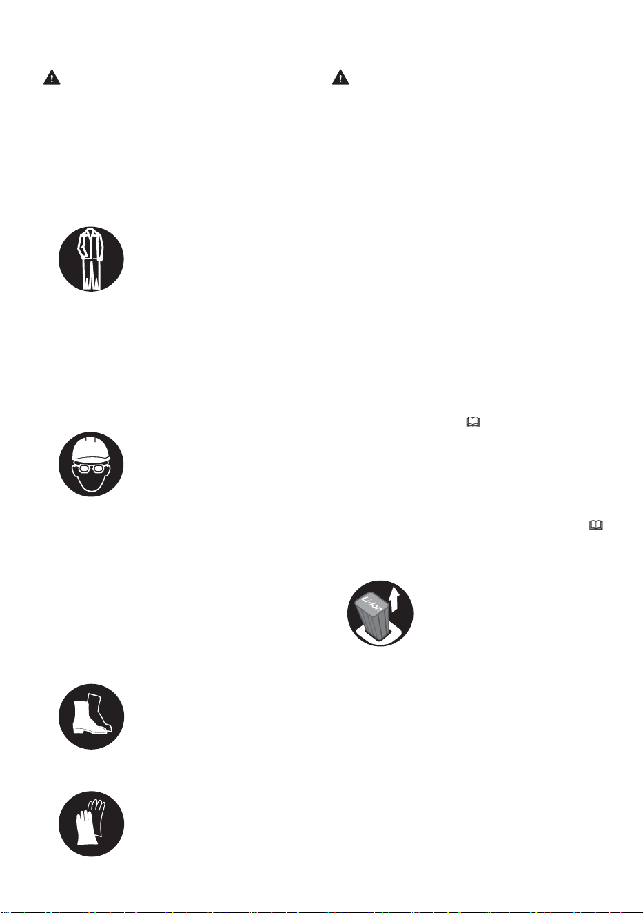
Always wear proper clothing and protective
apparel, including proper eye protection.
■ Loss of control and severe cut injuries may
result if hair, clothing or apparel make contact
with the moving saw chain or otherwise
become entangled in the components of the
pole pruner. To reduce the risk of severe per‐
sonal injury:
–
Wear sturdy and snug-fitting
clothing that also allows
complete freedom of move‐
ment.
–
Wear overalls or long pants
made of heavy material to
help protect your legs. Do
not wear shorts.
–
Avoid loose-fitting jackets, scarves, neck‐
ties, flared or cuffed pants, jewelry and any
other apparel that could be caught on
branches, brush or the moving chain.
–
Secure hair above shoulder level before
starting work.
■ To reduce the risk of eye injury:
–
Always wear goggles or
close-fitting protective
glasses with adequate top
and side protection that are
impact-rated and marked as
complying with ANSI Z87
"+".
–
To reduce the risk of injury to your face,
STIHL recommends that you also wear a
face shield or face screen over your goggles
or protective glasses.
■
To reduce the risk of head injury from falling
branches or other objects encountered during
work:
–
Wear an approved protective helmet.
■ Good footing is very important. To help main‐
tain a secure footing and reduce the risk of
injury while working:
–
Wear sturdy boots with non-
slip soles. Steel-toed safety
boots are recommended.
Do not wear sandals, flip-
flops, open-toed or similar
footwear.
■
To improve your grip and help protect your
hands:
–
Always wear heavy-duty
non-slip work gloves made
of leather or another wear-
resistant material when
handling the pole pruner or
its chain.
6.4 Pole Pruner
WARNING
■
To reduce the risk of electric shock:
–
Do not immerse the pole pruner in water or
other fluids.
–
Store the pole pruner indoors.
■ The saw chain has many sharp cutters. Con‐
tacting the cutters may result in serious lacera‐
tion injuries, even if the chain is not moving.
To reduce the risk of such injuries:
–
Keep hands, feet and other parts of your
body away from the chain.
–
Wear heavy-duty work gloves when han‐
dling the pole pruner or its chain.
–
Never touch a moving chain with your hand
or any other part of your body.
–
Cover the guide bar with a chain scabbard
before transporting or storing the pole pru‐
ner to reduce the risk of injury from inadver‐
tent contact.
■
Reactive forces, including kickback, can be
dangerous.
–
Pay special attention to the section of this
instruction manual on "Kickback and Other
Reactive Forces," 7.
■
This battery-powered pole pruner is intended
only for limbing. Use for other purposes may
increase the risk of personal injury and prop‐
erty damage.
–
Cut wood only.
–
Read and follow the operating instructions
in this manual for approved applications,
19.4.
■
To reduce the risk of personal injury to the
operator and bystanders:
–
Always release the trigger
switch and remove the bat‐
tery before assembling,
transporting, adjusting,
inspecting, cleaning, servic‐
ing, maintaining or storing
the pole pruner, and any
other time it is not in use.
■
Although certain unauthorized attachments
may fit your STIHL pole pruner, their use may
be extremely dangerous. Only attachments
supplied by STIHL or expressly approved by
STIHL for use with this specific model are rec‐
ommended.
–
Use only attachments supplied or expressly
approved by STIHL.
–
Never modify this pole pruner in any way.
–
Never attempt to modify or override the pole
pruner's controls or safety devices in any
way.
English 6 IMPORTANT SAFETY INSTRUCTIONS
8 0458-698-8621-B

–
Never use a pole pruner that has been
modified or altered from its original design.
■ If the pole pruner is dropped or subjected to
similar heavy impacts:
–
Check that it is undamaged, in good condi‐
tion and functioning properly before continu‐
ing work.
–
Check that the controls and safety devices
are working properly, 18.1.
–
Check the LEDs for error messages, 12.
–
Check that the battery has not been dam‐
aged. Never use or charge a malfunction‐
ing, damaged, cracked, leaking or deformed
battery.
–
Never work with a damaged or malfunction‐
ing pole pruner or battery. In case of doubt,
have the pole pruner and battery checked
by your authorized STIHL servicing dealer.
■
If the pole pruner or battery is damaged, not
working properly, has been left outdoors and
exposed to rain or damp conditions, or drop‐
ped into water or other liquid, its components
may no longer function properly and safety
devices may be inoperative. To reduce the risk
of personal injury and property damage:
–
Take the pole pruner and battery to your
authorized STIHL servicing dealer to be
checked before further operation.
■
Genuine STIHL replacement parts are specifi‐
cally designed to match your pole pruner and
meet safety and performance requirements.
Use of parts that are not authorized or
approved by STIHL may cause serious or fatal
injury or property damage.
–
STIHL recommends that only identical
STIHL replacement parts be used.
6.5 Using the Pole Pruner
6.5.1 Before Operation
WARNING
■
Misuse or unauthorized use may result in per‐
sonal injury and property damage.
–
Use the pole pruner only as described in
this instruction manual.
■ For proper assembly of the bar and chain:
–
Read and follow the instructions on mount‐
ing the guide bar and chain, 15.6.
■ The chain, guide bar and sprocket must match
each other in gauge and pitch. Before mount‐
ing or replacing:
–
Read the information on guide bar and
chain combinations, 27.
–
Read and follow the instructions on kick‐
back and other reactive forces, 7.
–
Select the shortest bar that will meet your
cutting needs. Longer bars add weight and
may be more difficult to control.
■
Proper tension of the chain is extremely impor‐
tant to maximize cutting performance and
reduce the risk of personal injury from chain
breakage, derailment or reactive forces:
–
Never cut with a loose chain. If the chain
becomes loose while cutting, switch off the
motor and remove the battery from the pole
pruner before tightening the chain. Never
attempt to adjust the chain while the battery
is inserted.
–
Read and follow the chain tensioning
instructions, 15.7.
–
Always make sure the chain sprocket cover
is tightened securely after tensioning the
chain in order to secure the bar. Never start
the pole pruner with a loose or missing
chain sprocket cover.
–
Check chain tension once more after tight‐
ening the chain sprocket cover.
–
Check chain tension periodically thereafter
at regular intervals (only after removing the
battery).
■
Using a pole pruner that is modified, dam‐
aged, improperly adjusted or maintained, or
not completely and securely assembled can
lead to a malfunction and increase the risk of
serious personal injury or death.
–
Never operate a pole pruner that is modi‐
fied, damaged, improperly maintained or not
completely and securely assembled.
–
Always check your pole pruner for proper
condition and operation before starting
work, particularly the retaining latch, Ergo-
Lever, trigger switch and cutting attachment.
–
Ensure that the retaining latch, Ergo-Lever
and trigger switch move freely and spring
back into place when released. The trigger
switch must not engage until the retaining
latch is unlocked.
–
Never attempt to modify or override the con‐
trols or safety devices in any way.
–
If your pole pruner or any part is damaged
or does not function properly, take it to your
authorized STIHL servicing dealer. Do not
use the pole pruner until the problem has
been corrected.
■
Before inserting the battery:
–
Check the contacts in the battery compart‐
ment for corrosion or other foreign matter.
Keep clean.
–
Never insert or use a malfunctioning, dam‐
aged, cracked, leaking or deformed battery.
6 IMPORTANT SAFETY INSTRUCTIONS English
0458-698-8621-B 9
–
Read and follow the instructions on switch‐
ing on the pole pruner, 17.1.
■ To help reduce the risk of serious personal
injury or death from unintentional starting:
–
Release the trigger switch and trigger switch
lockout before inserting the battery.
–
Release the trigger switch before removing
the battery.
–
Remove the battery before
assembling, transporting,
adjusting, inspecting, clean‐
ing, servicing, maintaining
or storing the pole pruner,
and any time it is not in use.
–
Never leave the pole pruner unattended
when the battery is inserted.
–
Never store the battery in the pole pruner.
■ Before switching on your pole pruner, take the
following steps to reduce the risk of personal
injury from loss of control or inadvertent con‐
tact with the chain:
–
Be sure that the guide bar and chain are
clear of you and all other obstructions and
objects, including the ground.
–
Never attempt to switch on the pole pruner
when the guide bar is in a cut or kerf. Doing
so could lead to reactive forces and injury.
–
Read and follow the instructions on switch‐
ing on the pole pruner, 17.1.
6.5.2 Holding and Controlling the Pole Pru‐
ner
WARNING
0000097178_001
■
0000-GXX-4803-A0
To maintain a firm grip and properly control
your pole pruner:
–
Keep the handles clean and dry at all times.
Keep them free of moisture, pitch, oil,
grease and resin.
■
To reduce the risk of serious or fatal injuries to
the operator or bystanders from loss of con‐
trol:
–
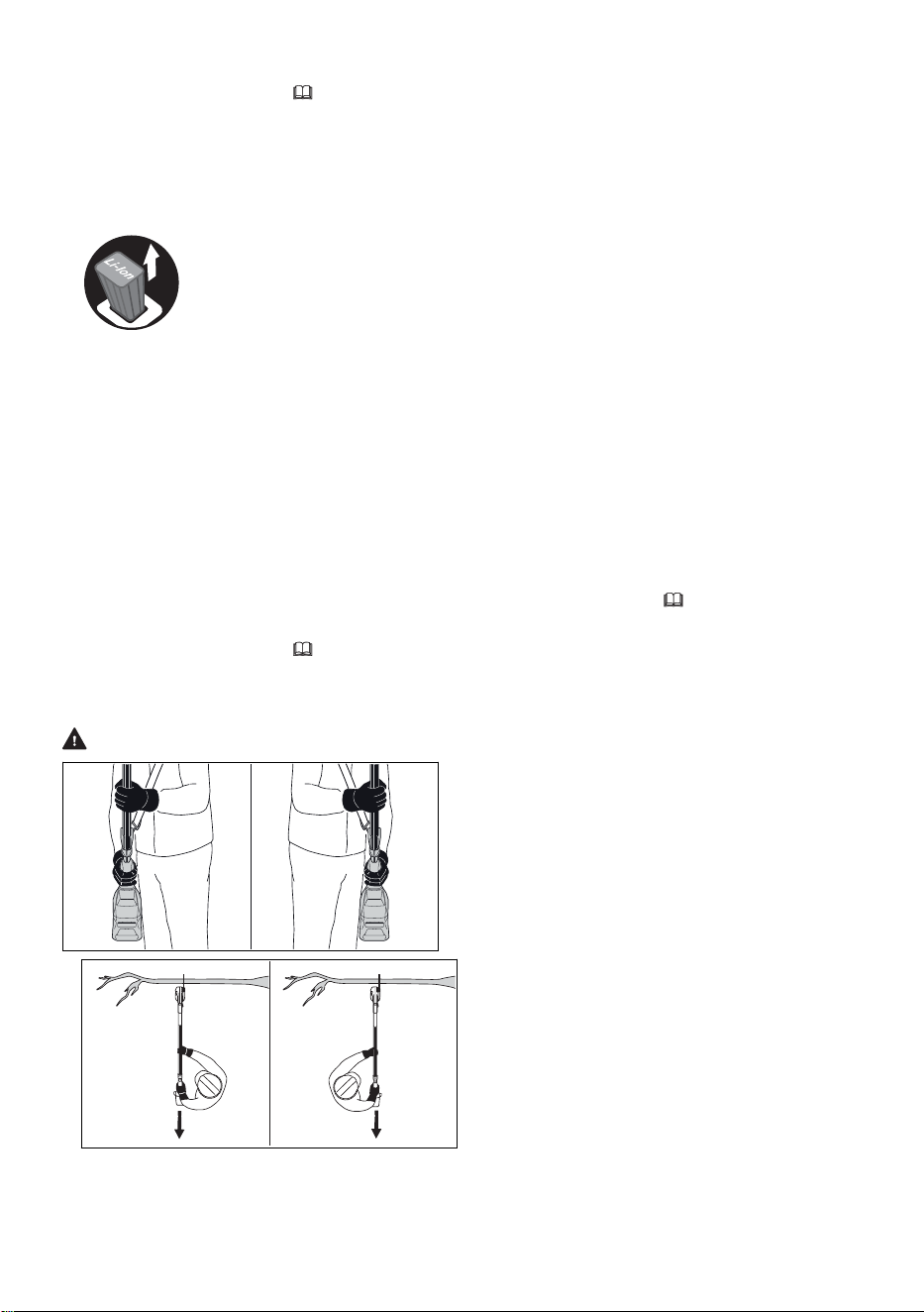
Always hold the pole pruner firmly with both
hands on the defined gripping surfaces dur‐
ing work.
–
Wrap your fingers tightly around the han‐
dles, keeping the handles cradled between
your thumb and forefinger (see illustrations).
–
Position the pole pruner in such a way that
all parts of your body are clear of the cutting
attachment whenever the battery is inser‐
ted. Stand to the left or right of the cut while
limbing, outside of the cutting plane (see
illustration).
–
Avoid contacting any object with the upper
quadrant of the tip of the guide bar. It may
cause kickback to occur.
–
Always hold the pole pruner firmly with both
hands when you are working.
–
Read and follow all warnings and instruc‐
tions in the chapter Kickback and Other
Reactive Forces, 7.
■
One-handed operation makes it difficult to
oppose and absorb reactive forces (pushback,
pull-in, kickback) without losing control of the
pole pruner. It also makes it difficult to prevent
the bar and chain from bouncing along a limb.
To reduce the risk of serious or fatal injury to
the operator or bystanders from loss of con‐
trol:
–
Never attempt to operate the pole pruner
with one hand.
■ To reduce the risk of serious or fatal cut inju‐
ries to the operator or bystanders from loss of
control, keep proper footing and balance at all
times:
–
Never work on a ladder, roof, in a tree or
while standing on any other insecure sup‐
port.
–
Take special care in overgrown or wet ter‐
rain and always watch for hidden obstacles
such as tree stumps, roots, rocks, holes and
ditches to avoid stumbling or falling.
–
Be extremely cautious when working on
slopes or uneven ground.
–
For better footing, always clear away fallen
branches, scrub and cuttings and other
material, objects or vegetation that can
increase the danger of slipping, tripping or
falling.
English 6 IMPORTANT SAFETY INSTRUCTIONS
10 0458-698-8621-B

–
Use extreme caution when cutting small-
size brush, branches and saplings because
slender material may catch the chain and
spring toward you or pull you off balance.
–
Do not overreach. Keep proper footing and
balance at all times.
–
Never switch on the pole pruner when the
guide bar is in a cut or kerf. Doing so could
lead to reactive forces and injury. Instead,
remove the guide bar from the cut and re-
enter at full speed, taking care to avoid con‐
tacting any object with the tip of the guide
bar.
–
For a pole pruner with an adjustable shaft,
expand the shaft only as far as necessary
for the intended application, but never cut
directly overhead. Ensure that the pole pru‐
ner is positioned no more than 60° from the
horizontal plane,
6.5.4.
■
Working above shoulder height can be tiring.
To reduce the risk of injury from fatigue:
–
Never hold the machine with your rear hand
on the control handle above shoulder
height.
–
Take frequent breaks.
■ The hook is designed to provide greater con‐
trol of the pole pruner while cutting. If you work
without the hook, the pole pruner may pull you
forward suddenly. This could cause loss of
control or, if the tip of the guide bar strikes an
object, kickback.
–
Always work with the hook to maintain bet‐
ter control of the pole pruner.
■ Applying pressure to the pole pruner when
reaching the end of a cut may cause the bar
and rotating chain to accelerate out of the kerf,
go out of control and strike some other object.
To reduce the risk of injury:
–
Use caution when approaching the end of a
cut.
–
Never put pressure on the pole pruner when
reaching the end of a cut.
6.5.3 Working Conditions
WARNING
■
Operate your pole pruner only under good visi‐
bility during favorable daylight conditions.
–
Postpone the work if the weather is windy,
foggy, rainy or inclement.
–
Never cut near power lines.
■ Your pole pruner is a one-person machine.
–
Do not allow other persons in the general
work area.
–
Bystanders, especially children, and ani‐
mals should not be allowed in the area
where it is in use.
–
Switch off the motor immediately if you are
approached.
■ To reduce the risk of injury to the operator,
bystanders and unauthorized users:
–
Never leave the pole pruner unattended
when the battery is inserted.
–
Switch off the pole pruner and remove the
battery during work breaks and any other
time the pole pruner is not in use.
■
Sparks generated from the operation of the
pole pruner may be capable of igniting com‐
bustible gases, liquids, vapors, dusts or other
combustible materials and substances. To
reduce the risk of fire and explosion:
–
Never operate the pole pruner in a location
where combustible gases, liquids, vapors,
dusts or other combustible materials and
substances are present.
–
Read and follow recommendations issued
by government authorities (e.g., OSHA) for
identifying and avoiding the hazards of com‐
bustible gases, liquids, vapors, dusts or
other combustible materials and substan‐
ces.
■
If a rotating chain strikes a rock or other hard
object, sparks may be created, which can
ignite flammable materials under certain cir‐
cumstances. Flammable materials can include
dry vegetation and brush, particularly when
weather conditions are hot and dry.
–
When there is a risk of fire or wildfire, do not
use your pole pruner around flammable
materials or around dry vegetation or brush.
–
Contact your local fire authorities or the U.S.
Forest Service if you have any question
about whether vegetation and weather con‐
ditions are suitable for the use of a pole pru‐
ner.
■
Using this pole pruner and sharpening its
chain can generate dust, oil mist and other
substances containing chemicals known to
cause respiratory problems, cancer, birth
defects and other reproductive harm.
–
Consult governmental agencies such as
EPA, OSHA, CARB and NIOSH and other
authoritative sources on hazardous materi‐
als if you are unfamiliar with the risks asso‐
ciated with the particular substances you
are cutting or with which you are working.
■
Inhalation of certain dusts, especially organic
dusts such as mold or pollen, can cause sus‐
ceptible persons to have an allergic or asth‐
matic reaction. Substantial or repeated inhala‐
6 IMPORTANT SAFETY INSTRUCTIONS English
0458-698-8621-B 11

tion of dust or other airborne contaminants,
especially those with a smaller particle size,
may cause respiratory or other illnesses. This
includes wood dust, especially from hard‐
woods, but also from some softwoods such as
Western Red Cedar.
–
Control dust (such as saw dust) and mists
(such as oil mist from chain lubrication) at
the source where possible.
–
Always work with a properly sharpened
chain, which produces wood chips rather
than fine dust.
–
To the extent possible, operate the pole pru‐
ner so that the wind or operating process
directs any dust, mist or other particulate
matter raised by the pole pruner away from
the operator.
–
When respirable dust or other particulate
matter cannot be kept at or near back‐
ground levels, always wear a respirator that
is approved by NIOSH and rated for work‐
site-specific conditions. Follow the recom‐
mendations of governmental authorities
(e.g., OSHA/NIOSH) and occupational and
trade associations.
■ If the vegetation being cut or the surrounding
ground is coated with a chemical substance,
such as pesticide or herbicide:
–
Read and follow the instructions and warn‐
ings that accompanied the substance coat‐
ing the vegetation or surrounding ground.
■
Breathing asbestos dust is dangerous and can
cause severe or fatal illness, respiratory illness
or cancer, including mesothelioma. The use
and disposal of asbestos-containing products
is strictly regulated by OSHA and the EPA.
–
Do not use your pole pruner to cut or disturb
asbestos or asbestos-containing products.
–
Stop work immediately and contact the rele‐
vant state and local authorities and/or EPA,
your employer or local OSHA representative
if you have reason to believe that you might
be disturbing asbestos.
■
Repeated contact with waste oil can cause
skin cancer and its use is harmful to the envi‐
ronment.
–
Do not use waste oil to lubricate the bar and
chain of your STIHL pole pruner.
6.5.4 Operating Instructions
WARNING
■
To reduce the risk of severe personal injuries
from unintentional starting:
–
Never touch a chain with your hand or any
part of your body when the battery is inser‐
ted, even when the chain is not rotating.
■
To reduce the risk of cut injuries:
–
Keep hands and feet away from the saw
chain.
–
Never touch a moving chain with your hand
or any other part of your body.
–
Always pull the unit out of the cut with the
chain running to reduce the possibility of
pinching the cutting attachment.
–
If the chain becomes clogged, always
switch off the motor, remove the battery and
make sure the chain has stopped before
cleaning.
–
If a pinch occurs that traps the bar/chain,
switch off the motor and remove the battery
before attempting to remove the bar.
–
Don't put pressure on the pole pruner when
reaching the end of a cut. The pressure may
cause the bar and rotating chain to pop out
of the cut or kerf, go out of control and strike
some other object.
■
The chain continues to move for a short period
after the trigger switch is fully released.
–
Wait for the chain to stop before walking
with the pole pruner or putting it down.
■ In the event of an emergency:
–
Switch off the motor immediately and
remove the battery.
■ Contacting foreign objects while sawing might
cause the chain to break or be thrown, or
cause the pole pruner to propel dangerous
debris or kick back in the direction of the oper‐
ator. To reduce the risk of severe or fatal per‐
sonal injury caused by contact with foreign
objects:
–
Inspect the branch before cutting.
–
Remove any foreign objects to ensure that
the wood is free of materials such as nails,
spikes, cables, or wires.
–
Before starting a cut, ensure that it can be
completed without contacting surrounding
objects or structures such as fencing or
stonework.
■
The power tool has a large range. To reduce
the risk of personal or even fatal injury to
bystanders from falling objects or inadvertent
contact with the cutting attachment:
English 6 IMPORTANT SAFETY INSTRUCTIONS
12 0458-698-8621-B
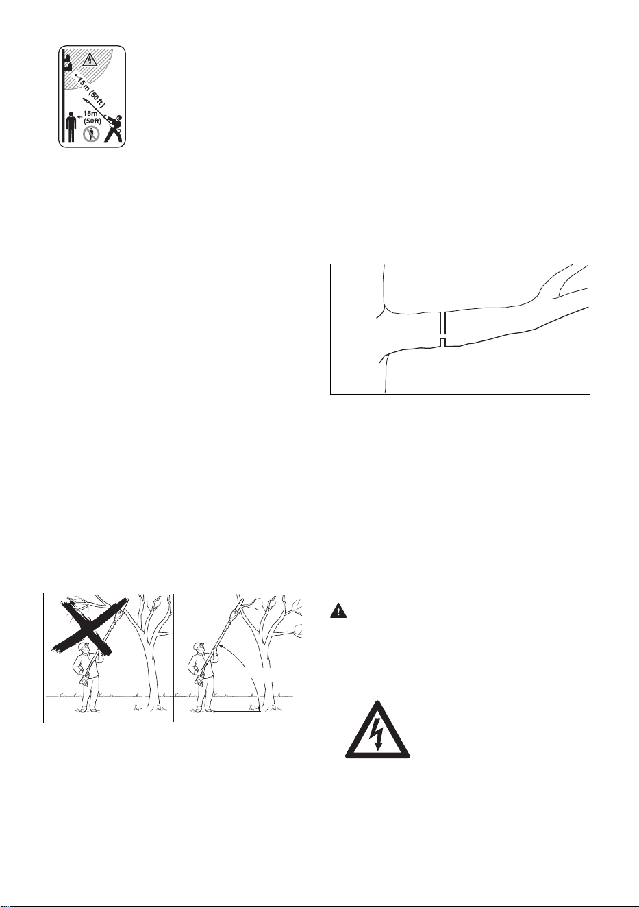
–
Always keep bystanders at
least 50 ft. (15 m) away when
the power tool is in use.
–
Do not allow other persons in the general
work area.
■ Check the chain and guide bar at regular short
intervals during operation, or immediately if
there is a change in cutting behavior:
–
Switch off the motor and remove the bat‐
tery.
–
Check the condition and tension of the
chain. Look for damage to the chain or
guide bar.
–
If the chain cannot be properly tensioned, or
if other components of the pole pruner are
worn or damaged, stop work immediately
and take your pole pruner to an authorized
STIHL servicing dealer for inspection, repair
or maintenance.
■
If a tree is rotted, it could snap and fall toward
the operator while being cut. To reduce the
risk of injury from falling debris, take the fol‐
lowing steps before starting work:
–
Observe the general condition of the tree.
Inspect for decay or rot in the trunk and
branches. Look for dead branches that
could vibrate loose and fall on the operator.
–
To prevent a larger branch from splitting,
make a shallow relief cut at the bottom of
the branch before making a finishing cut
from the top. This procedure will help
reduce damage to the tree and also help
make the fall of the limb more predictable.
max 60°
0000-GXX-4757-A2
■
To reduce the risk of severe or even fatal
injury from falling objects:
–
Never cut directly overhead. Hold the pole
pruner no more than 60° from the horizontal
plane (see illustration).
–
Never stand underneath the limb being cut.
–
Watch for falling limbs. Objects may fall in
unexpected directions.
–
Establish an escape route away from where
the limbs may fall.
–
As soon as the limbed branch starts to fall,
step away and keep a sufficient distance
away.
–
Keep the work area clear and free of obsta‐
cles and fallen limbs. Place all tools and
equipment out of your immediate work area
and escape route.
■
There is an increased danger of pinching the
pole pruner when cutting branches under ten‐
sion. The tension in wood can also release
suddenly and with great force, propelling the
limb or pole pruner into the operator, causing
injury or loss of control.
2
1
0000-GXX-C576-A0
B
A
■
■ To reduce the risk of severe or fatal personal
injury from loss of control when cutting wood
under tension:
–
Always start with a relieving cut (1) at the
compression side (A) of the branch, and
then make a cross-cut (2) at the tension
side (B).
–
If a pinch occurs that traps the bar/chain,
switch off the motor, remove the battery and
remove the pole pruner from the branch,
exercising caution that the limb does not
suddenly snap or release.
DANGER
■
Electricity can jump from one point to another
by means of arcing. Higher voltage increases
the distance electricity can arc. Electricity can
also move through branches, especially if they
are wet. To reduce the risk of electrocution:
–
Never operate this pole pru‐
ner in the vicinity of any
wires or cables that may be
carrying electric current.
Look carefully for concealed
wires before starting work.
–
Never cut near power lines.
–
Hold the power tool only at
the designated gripping sur‐
faces, but do not rely on
them for protection against
electric shock. This pruner
is not insulated.
6 IMPORTANT SAFETY INSTRUCTIONS English
0458-698-8621-B 13
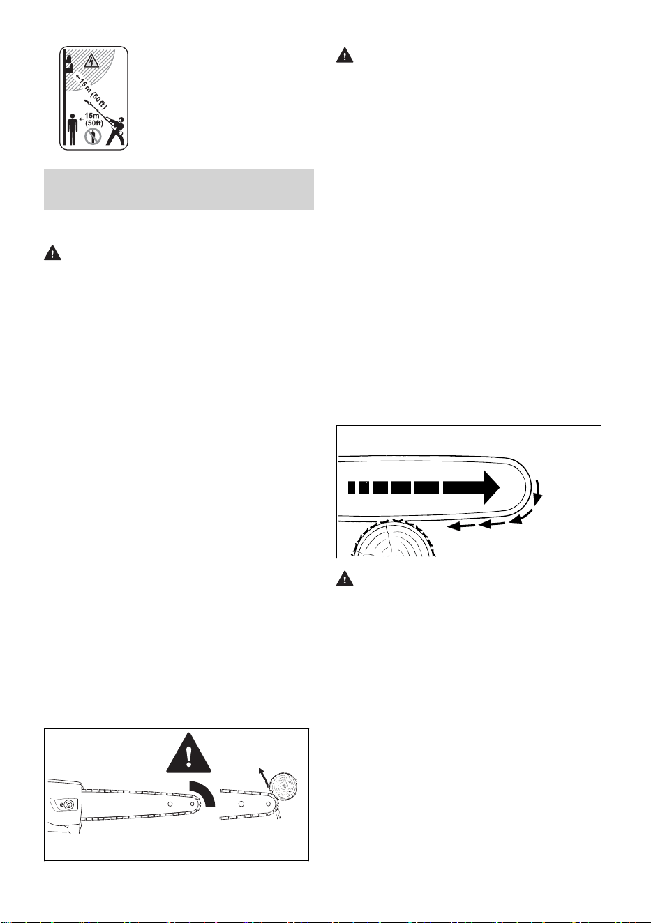
–
Maintain a clearance of at least
50 ft. (15 m) between the pole
pruner (including any branches
it is contacting) and any electri‐
cal line carrying live current.
–
Before working with less clear‐
ance, contact your electric util‐
ity and make sure the current
is turned off.
7 Kickback and Other Reac‐
tive Forces
7.1 Reactive Forces
WARNING
■ Reactive forces may occur any time the chain
is rotating. Reactive forces can cause serious
or fatal personal injury.
■
The powerful forces used to cut wood can be
reversed and work against the operator. If the
rotating saw chain is suddenly and signifi‐
cantly slowed or stopped by contact with any
solid object such as a branch, or is pinched,
the reactive forces may occur instantly.
■
These reactive forces may result in loss of
control, which, in turn, may cause serious or
fatal injury.
–
An understanding of the causes of these
reactive forces may help you avoid the ele‐
ment of surprise and loss of control. Sur‐
prise contributes to accidents.
■
Because of the design of the pole pruner, the
reactive forces experienced when working with
it are generally not as severe as those
encountered with a chain saw.
–
Nevertheless, always maintain a proper grip
and good footing to control the pole pruner
when you experience such forces.
The most common reactive forces are:
–
Kickback
–
Pull-in
–
Pushback
7.2 Kickback
7.2.1 Kickback
0000097293_001
WARNING
■ Kickback may occur when the moving chain
near the upper quadrant of the bar nose con‐
tacts a solid object or is pinched.
■
When this occurs, the energy driving the chain
can create a force that moves the pole pruner
in a direction opposite to the chain movement
at the point where the chain is slowed or stop‐
ped. This may cause the bar to move upward.
7.2.2 To Avoid Kickback
The best protection from personal injury that may
result from kickback is to avoid kickback situa‐
tions:
1)
Be aware of the location of the guide bar
nose at all times.
2)
Never let the nose of the guide bar contact
any object. Do not cut limbs with the nose of
the guide bar. Be especially careful near wire
fences and when cutting small, tough limbs,
which may easily catch the chain.
3)
Cut only one limb at a time.
7.3 Pull-in
0000-GXX-1348-A0
WARNING
■
Pull-in occurs when the chain on the bottom of
the bar is suddenly stopped or significantly
slowed when it is pinched, caught or encoun‐
ters a foreign object in the wood. The reaction
of the chain pulls the pole pruner forward.
■
Pull-in usually occurs when the chain is not
rotating at full speed before it contacts the
wood.
■
To reduce the risk of pull-in:
–
Be alert to forces or situations that may
cause material to pinch the chain at the bot‐
tom of the bar.
–
Always start a cut with the chain rotating at
full speed.
English 7 Kickback and Other Reactive Forces
14 0458-698-8621-B
7.4 Pushback
0000-GXX-1349-A0
WARNING
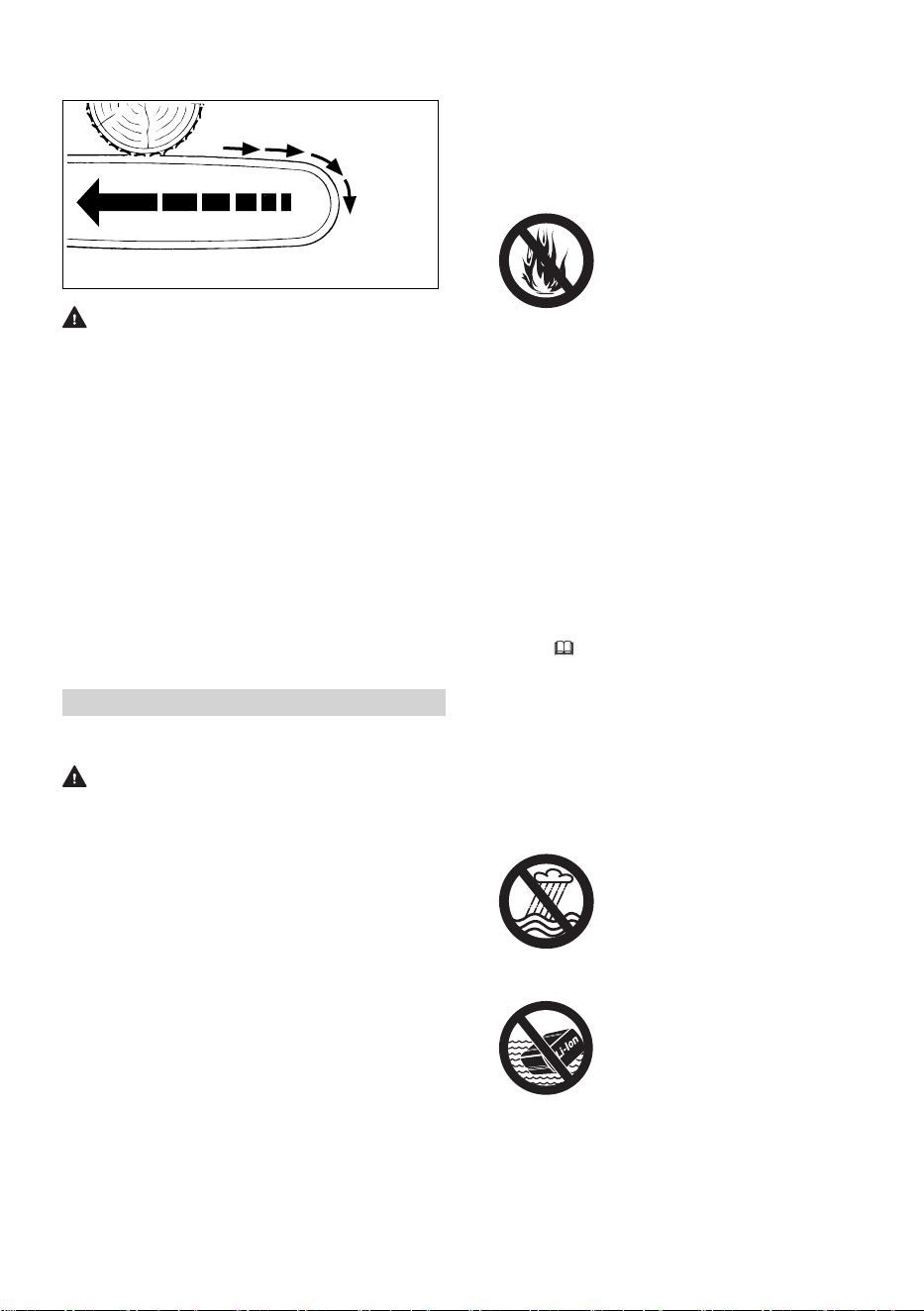
■ Pushback occurs when the chain on the top of
the bar is suddenly stopped or significantly
slowed when it is pinched, caught or encoun‐
ters a foreign object in the wood. The reaction
of the chain may drive the pole pruner rapidly
straight back toward the operator.
■
Pushback usually occurs when the top of the
bar is used for cutting.
■ To reduce the risk of pushback:
–
Be alert to forces or situations that may
cause material to pinch or bind the top of
the bar.
–
Do not cut more than one limb at a time.
–
Do not twist the bar when withdrawing it
from an underbuck cut because the chain
can pinch or bind.
8 Battery Safety
8.1 Warnings and Instructions
WARNING
■
Read and follow the safety precautions on the
battery and all warnings and instructions that
accompany it.
■
Use of unauthorized batteries can damage the
power tool and result in fire, explosion and
personal injury and property damage.
–
Use only genuine STIHL AR or AP series
batteries with this power tool.
■ Use of STIHL AR or AP series batteries for
any purpose other than powering STIHL prod‐
ucts could be extremely dangerous.
–
Use STIHL AR and AP series batteries only
to power compatible STIHL products.
■ Use of unauthorized chargers can damage the
battery and result in fire, explosion and per‐
sonal injury and property damage.
–
Charge STIHL AP series batteries only with
genuine STIHL AL 101, AL 301, AL 301-4 or
AL 501 series chargers.
–
Charge STIHL AR series backpack batteries
only with genuine STIHL AL 301, AL 301-4
or AL 501 series chargers.
■
The battery contains safety features and devi‐
ces which, if damaged, may allow the battery
to generate heat, rupture, leak, ignite or
explode.
–
Never heat the battery
above 212 °F (100 °C).
–
Never incinerate or place
the battery on or near fires,
stoves or other high-tem‐
perature locations.
–
Never use or charge a malfunctioning, dam‐
aged, cracked, leaking or deformed battery.
–
Never open, disassemble, crush, drop, sub‐
ject to heavy impact or otherwise damage
the battery.
–
Never expose the battery to microwaves or
high pressures.
–
Never insert objects into the battery's cool‐
ing slots.
■ Extreme temperatures may cause the battery
to generate heat, rupture, leak, ignite or
explode, resulting in severe or fatal personal
injury and property damage.
–
Never charge, use or store the battery out‐
side the specified ambient temperature lim‐
its, 26.6.
■
To reduce the risk of personal injury and prop‐
erty damage in the event the battery emits
smoke, has an unusual smell or feels unusu‐
ally hot while using, charging or storing:
–
Immediately discontinue using or charging
the battery. Contact the authorities in the
event of fire or explosion.
■
To reduce the risk of a short circuit, which
could lead to electric shock, fire and explosion:
–
Keep STIHL AR 1000,
2000, 3000 backpack bat‐
teries dry. Protect from rain,
water and other liquids.
Attach the rain cover to the
battery before starting work
in rain or in very damp con‐
ditions.
–
If a STIHL AP or AR L bat‐
tery has been exposed to
rain during work, remove it
from the product and allow
it to dry indoors. Make sure
it is completely dry before
charging or using.
–
Never immerse any STIHL
battery in water or other liq‐
uids.
–
Never bridge the battery terminals with
wires or other metallic objects.
8 Battery Safety English
0458-698-8621-B 15

–
Keep a battery that is not in use away from
small metal objects capable of conducting
electricity (e.g., paper clips, nails, coins,
keys).
–
Store the battery indoors in a dry room.
–
Never store the battery in damp or corrosive
environments or in conditions that could
lead to corrosion of its metal components.
–
Never store the battery in the power tool.
–
When storing the battery, maintain a charge
of 40 % to 60 % for STIHL AP series batter‐
ies and a charge of 30 % to 45 % for STIHL
AR series batteries (2 green LEDs).
–
If storing the battery in the charger, discon‐
nect the charger from the outlet.
–
Protect the battery from exposure to corro‐
sive agents such as garden chemicals and
de-icing salts.
–
Protect the battery from exposure to con‐
ductive liquids such as salt water.
–
Do not attempt to repair, open or disassem‐
ble the battery.
■ Leaking battery fluid is potentially harmful and
can cause skin and eye irritation, chemical
burns and other serious personal injury.
–
Avoid contact with skin and eyes.
–
Use an inert absorbent such as sand on
spilled battery fluid.
–
In the event of accidental contact, immedi‐
ately rinse the contact area thoroughly with
mild soap and water.
–
If fluid gets into your eye(s): do not rub.
Rinse water over the open eye(s) for at
least 15 minutes and seek medical atten‐
tion.
■
A battery fire can be dangerous. To reduce the
risk of severe personal injury and property
damage in the event of fire:
–
Evacuate the area. Fire can spread rapidly.
Stay clear of any vapors generated and
maintain a safe distance.
–
Contact the fire department.
–
Although water can be used to put out a
battery fire, use of a multi-purpose dry
chemical fire extinguisher is preferable.
–
Consult the fire department regarding
proper disposal of a burned battery.
9 Maintenance, Repair and
Storage
9.1 Warnings and Instructions
WARNING
■
To reduce the risk of fire, electric shock or
other personal injury and property damage:
–
Strictly follow the cleaning and maintenance
instructions in the appropriate sections of
this instruction manual.
–
STIHL recommends that all repair work be
performed by authorized STIHL servicing
dealers.
■
Unintentional starting may result in personal
injury or property damage. To reduce the risk
of personal injury and property damage from
unintentional starting:
–
Remove the battery before
inspecting the pole pruner
or carrying out any clean‐
ing, maintenance or repair
work, before storing, and
any other time it is not in
use.
■
Proper maintenance will help maintain cutting
performance and reduce the risk of personal
injury caused by chain derailment and reactive
forces.
–
Wear gloves when handling the saw chain.
–
Keep the chain, guide bar and sprocket
clean.
–
Replace the chain and guide bar when they
become worn or damaged.
–
Keep the chain sharp and at proper tension.
–
Tighten all nuts, bolts and screws after each
use.
■ Return the pole pruner immediately for mainte‐
nance whenever there is a change in its oper‐
ating characteristics.
■
Use of parts that are not authorized or
approved by STIHL may cause serious or fatal
injury or property damage.
–
STIHL recommends that only identical
STIHL replacement parts be used for repair
or maintenance.
■
To reduce the risk of short circuit and fire:
–
Keep the battery guides free of foreign mat‐
ter. Clean as necessary with a dry cloth or
soft, dry brush.
■
Improper storage can result in unauthorized
use, damage to the pole pruner and battery,
and an increased risk of fire, electric shock
and other personal injury or property damage.
–
Remove the battery from the pole pruner
before storing.
English 9 Maintenance, Repair and Storage
16 0458-698-8621-B
–
Never store the pole pruner with the battery
inserted.
–
When storing the battery, maintain a charge
of 40 % to 60 % for STIHL AP series batter‐
ies and a charge of 30 % to 45 % for STIHL
AR series batteries (2 green LEDs).
–
If storing the battery in the charger, discon‐
nect the charger from the outlet.
–
Store the pole pruner and battery indoors in
a dry, secure place that cannot be accessed
by children or other unauthorized users.
–
Never store the battery in the pole pruner or
in a container with small metal objects capa‐
ble of conducting electricity (e.g., paper
clips, nails, coins, keys).
NOTICE
■ Always release tension on the chain after fin‐
ishing work. The chain contracts as it cools
down. If it is not slackened, it can damage the
drive shaft and bearings. Properly re-tension
the chain before using the pole pruner again.
10 Before Starting Work
10.1 Preparing the Pole Pruner for
Operation
Before starting work:
►
Fully charge the battery,
11.
►
Assembling the Pole Pruner, 15.
►
Mount the guide bar and saw chain, 15.6.
►
Tension the chain, 15.7.
►
Fill the chain oil tank, 15.8.2.
► Check the controls for proper function and
condition, 18.1.
►
Check the chain oil flow rate, 18.2.
►
Adjust the length of the drive tube, 19.1.
►
Put on and adjust the shoulder strap, 19.3.
10.2 Connecting to the STIHL con‐
nected App
►
Turn on your mobile device's Bluetooth
®
inter‐
face.
►
Turn on the battery's Bluetooth
®
interface,
13.1
► Download the STIHL connected App from
Google Play or the App Store.
► Follow in-app instructions for creating a new
user account. Returning users should log in
their existing account information.
► Follow the step-by-step instructions for adding
the battery to your equipment list.
11 Charging the Battery
11.1 Setting up the Charger
WARNING
■ Read and follow the safety precautions on the
battery and charger and all warnings and
instructions that accompany those products.
To reduce the risk of short circuit, which could
lead to electric shock, fire and explosion,
make sure the charger and its components are
dry and not damaged. Read and follow the
warnings and instructions in your charger's
manual. For optimum performance, observe
the recommended ambient temperature
ranges,
26.7.
WARNING
■ A typical household electric circuit is between
15 and 20 amps. A single STIHL AL 501
charger draws approximately 4.8 amps. A sin‐
gle AL 301 or AL 301-4 charger draws approx‐
imately 4.4 amps and an AL 101 approxi‐
mately 1.3 amps. To reduce the risk of fire
from overloading an electrical circuit:
–
Ensure the electrical system is rated to with‐
stand the expected electrical draw before
charging your battery.
–
Charge multiple batteries one at a time or
on separate circuits, unless you know your
circuit can handle the total expected draw
from multiple chargers.
WARNING
■ Since the charger heats up during the charg‐
ing process, do not operate the charger on a
combustible surface or in a location where
combustible gases, liquids, vapors, dusts or
other materials and substances are present.
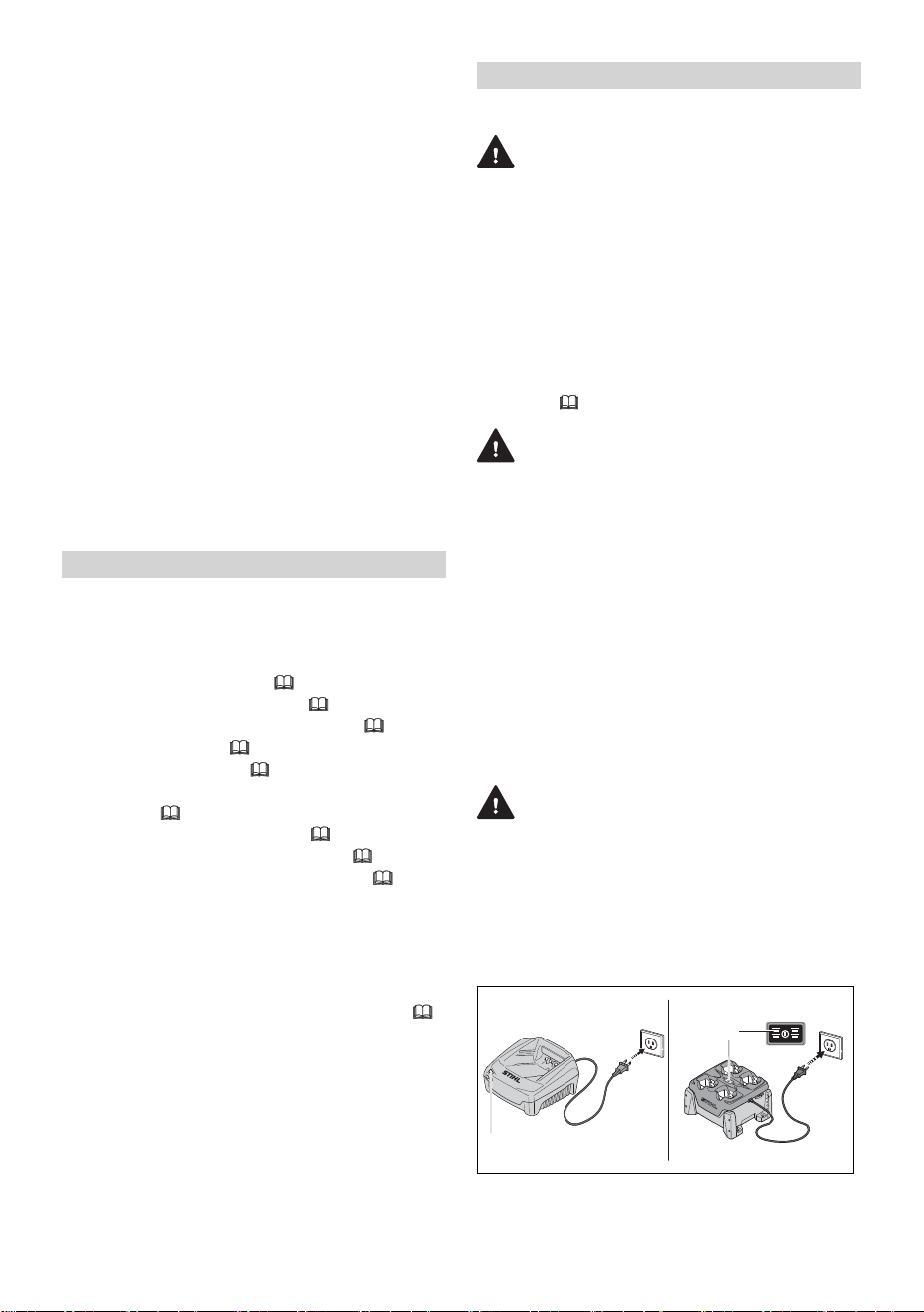
To set up the charger:
3
2
4
1
1
2
3
4
0000082682_005
10 Before Starting Work English
0458-698-8621-B 17
► Insert the plug (3) into a properly installed
electrical outlet (4) matching the voltage and
electrical frequency stated on the charger's
rating plate.
The charger runs a self-test immediately after it
is plugged in. The charger LED (1) will glow
green for about 1 second, then it will glow red
briefly before going out. Once the LED goes out,
the self-test is complete and the charger is ready
to charge the battery.
► Position the power supply cord (2) so that it
will not be stepped on, tripped over, come in
contact with sharp objects or moving parts or
otherwise be subjected to damage or stress.
11.2 Charging
WARNING
■ STIHL batteries contain safety features and
devices which, if damaged, may allow the bat‐
tery to generate heat, rupture, leak, ignite or
explode. Never charge a malfunctioning, dam‐
aged, cracked, leaking or deformed battery, or
use a charger that has been damaged. Never
insert a wet battery or battery adapter. Never
use a wet charger. Follow all product-specific
warnings and instructions accompanying your
battery and charger.
A battery is not fully charged when it ships from
the factory. STIHL recommends that you fully
charge the battery before using it the first time.
Read and follow the warnings and instructions in
your charger's manual. For optimum perform‐
ance, observe the recommended ambient tem‐
perature ranges,
26.7.
The battery heats up during operation of the
power tool. If a hot battery is connected to the
charger, it may be necessary for it to cool down
before charging starts. The charging process
begins only after the battery has cooled down
sufficiently.
Charging time depends on a number of factors,
including battery condition and the ambient tem‐
perature. For a complete list of approximate
charging times, see www.stihl.com/charging-
times.
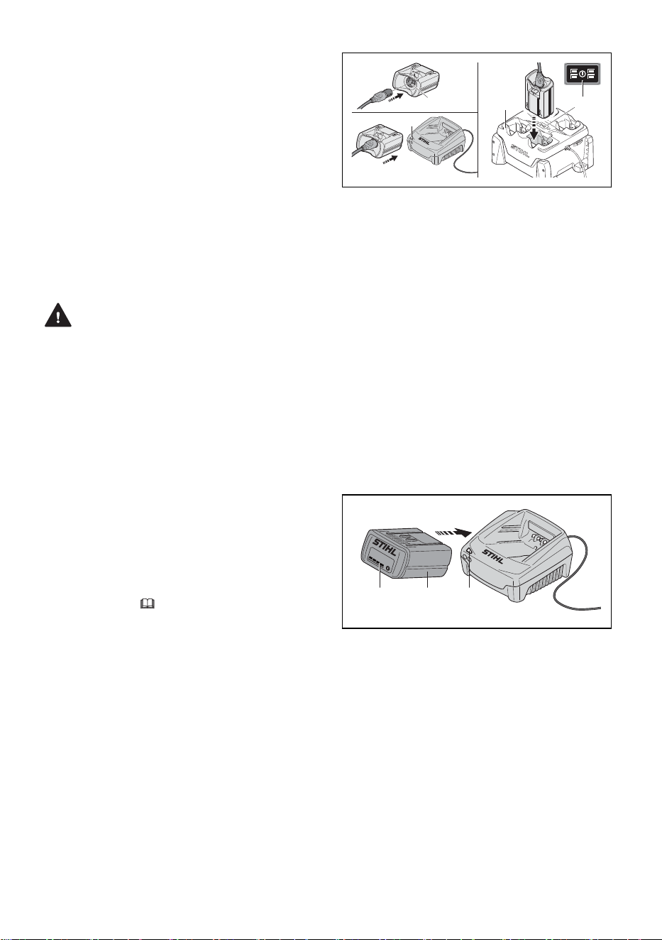
To charge an AR battery:
3
1
3
4
5
4
5
2
0000081894_003
► Push the plug of the connecting cord (1) into
the socket (2) of the ADA 100 (3) until it stops.
► Push the ADA 100 into the charger (5) until it
stops.
The LED (4) on the charger glows green when
the battery is charging.
The LEDs on the AR battery glow green and
show the state of charge.
When the LEDs on the battery turn off, the
charging process is complete and the charger
will shut itself off. The ADA 100 can be
removed from the charger.
► Disconnect the power supply cord from the
electrical outlet when the charger is not in use
for extended periods of time.
► Charge STIHL AR backpack batteries only
with genuine STIHL AL 301, AL 301-4 or AL
501 series chargers.
To charge an AP battery:
2
3
4
1
0000083481_002
► Push the battery (2) into the charger (3) until it
stops.
The LED on the charger glows green when the
battery is charging.
The LEDs (1) on the AP battery glow green
and show the state of charge.
When the LEDs on the battery go out, the
charging process is complete and the charger
will shut itself off. The AP battery can be
removed from the charger.
► Disconnect the power supply cord from the
electrical outlet when the charger is not in use
for extended periods of time.
► Charge STIHL AP series batteries only with
genuine STIHL AL 101, AL 301, AL 301-4 or
AL 501 series chargers.
English 11 Charging the Battery
18 0458-698-8621-B
12 LED Diagnostics and
Acoustic Signals
12.1 STIHL AP Battery
12.1.1 Battery Status
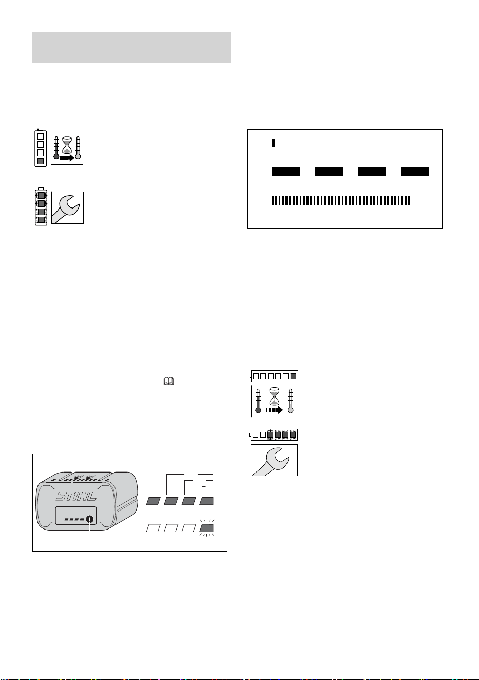
Four LEDs show the status of the battery. These
LEDs can glow or flash green or red.
If one LED glows red continu‐
ously: the battery is either too hot
or too cold. Allow the battery to
warm up or cool down gradually at
an ambient temperature of about
50 °F to 68 °F (10 °C to 20 °C).
If all 4 LEDs flash red: the battery
has a malfunction and must be
replaced. Do not attempt to
charge, use or store the battery.
12.1.2 Power Tool Status
The same LEDs on the battery will indicate the
status of the power tool.
If three LEDs glow red continuously: the power
tool motor is too hot. Allow the motor to cool
down.
If three LEDs flash red when you activate the
trigger switch: the power tool has an electrical
malfunction. Do not operate the power tool. Have
it checked by an authorized STIHL servicing
dealer before use or storage.
For troubleshooting information,
25.
12.1.3 Charge Status
The LEDs on the battery also show the battery's
state of charge.
To determine the battery's state of charge:
0000079877_002
20-40%
40-60%
60-80%
80-100%
0-20%
1
► Press the button (1) on the battery.
The LEDs on the battery will glow or flash
green for about 5 seconds and indicate the
state of charge (see illustration).
For example:
If four green LEDs glow continuously: full charge.
If one green LED is flashing: less than 20 %
charge.
12.2 STIHL AR Backpack Battery
12.2.1 Battery Status
Six LEDs and an acoustic signal indicate the sta‐
tus of the battery.
1
2
3
.......
0000-GXX-3229-A1
1 A short beep
The acoustic signal works as it should.
2 Four or six (AR L) long beeps
The battery's charge is low. Recharge the
battery.
3 Rapid succession of short beeps
There is a malfunction in the battery. The sig‐
nal stops automatically after a few seconds.
Do not attempt to charge, use or store the
battery. Replace the battery.
These LEDs can glow or flash green or red.
If one LED glows red continu‐
ously: the battery is either too hot
or too cold. Allow the battery to
warm up or cool down gradually at
an ambient temperature of about
50 °F to 68 °F (10 °C to 20 °C).
If the four right side LEDs flash
red and a rapid succession of sev‐
eral short beeps is emitted: the
battery has a malfunction and
must be replaced. Do not attempt
to charge, use or store the bat‐
tery.
► Be aware that your ability to hear the acoustic
signal may be reduced when wearing hearing
protection.
12.2.2 Power Tool Status
When the battery is connected to the power tool,
the same LEDs on the battery will indicate the
status of the power tool.
If three LEDs glow red continuously: the power
tool motor is too hot. Allow the motor to cool
down.
If three LEDs flash red when you activate the
trigger switch: the power tool has an electrical
12 LED Diagnostics and Acoustic Signals
English
0458-698-8621-B 19
malfunction. Do not operate the power tool. Have
it checked by an authorized STIHL servicing
dealer before use or storage.
For troubleshooting information, 25.
12.2.3 Charge Status
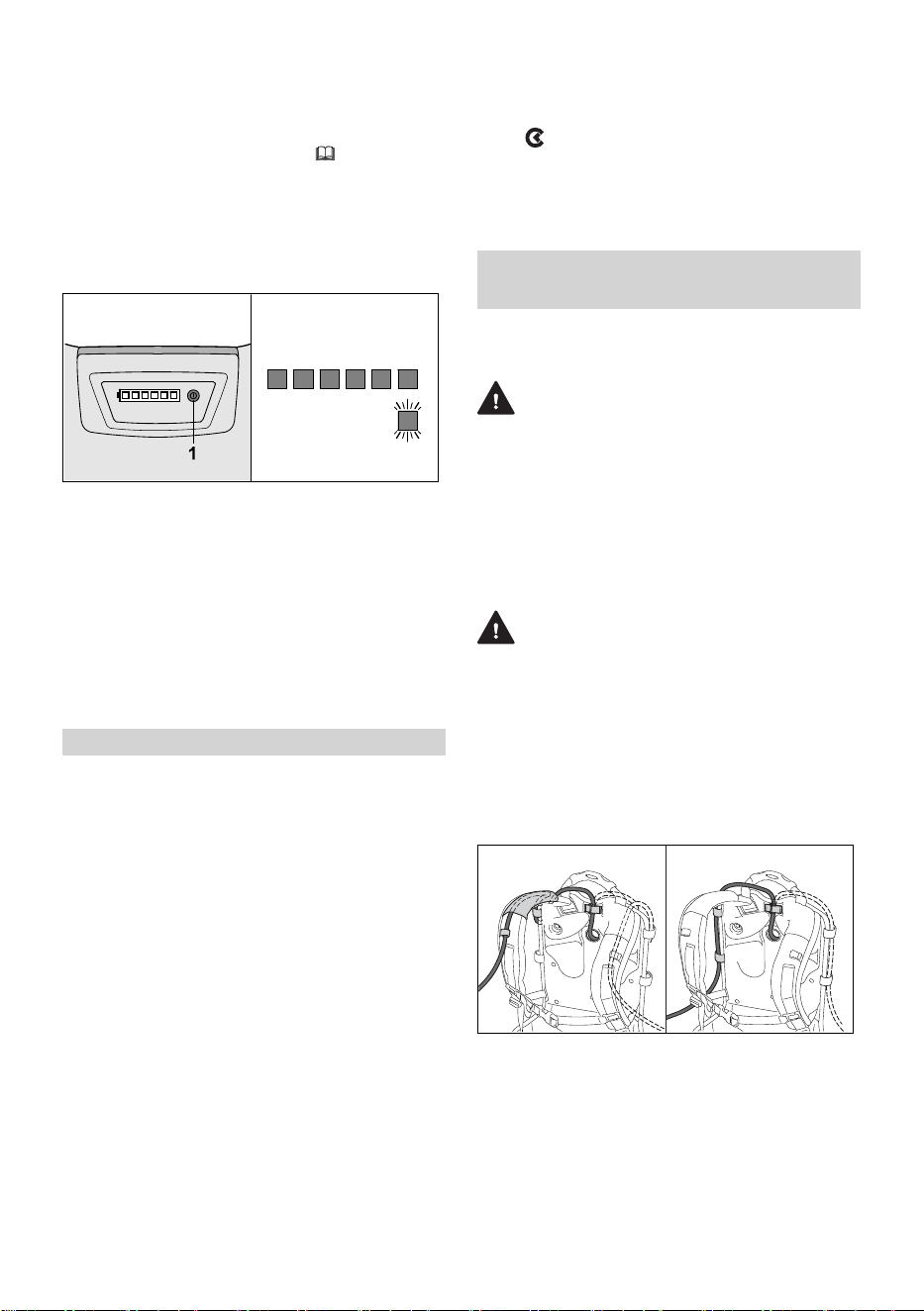
The LEDs and acoustic signals on the battery
also indicate the battery's state of charge.
To determine the battery's state of charge:
0000-GXX-2673-A0
100 % 0 %
► Press the button (1) on the backpack battery.
A single short beep will be emitted. The LEDs on
the battery will glow or flash green for about
5 seconds and indicate the state of charge (see
illustration).
For example:
If six green LEDs glow continuously: full charge.
If one green LED is flashing and four long beeps
are emitted: less than 20 % charge.
13 Bluetooth® Radio Interface
13.1
Turning the Bluetooth
®
Inter‐
face On
► Press and hold the push button for about
3 seconds.
If the Bluetooth
®
LED next to the connected
symbol glows blue for about 3 seconds, the
battery's Bluetooth
®
interface is on.
13.2
Turning the Bluetooth
®
Inter‐
face Off
► Press and hold the push button for about
3 seconds.
If the Bluetooth
®
LED flashes blue six times,
the Bluetooth
®
interface is off.
13.3 Resetting the Battery to Fac‐
tory Settings via Bluetooth
®
(AP 300 S and AP 500 S only)
Resetting the battery to the factory setting means
that all user-specific data will be deleted.
► Press the push button four (4) times in quick
succession and keep it pressed on the fourth
time until the "BLUETOOTH®“ LED next to
the
symbol flashes blue.
► Then release the push button immediately.
► Connect the battery to the STIHL connected
App to confirm that all user-specific data has
been deleted.
14 STIHL AR Backpack Bat‐
tery
14.1 Positioning and Adjusting the
Connecting Cord
WARNING
■ To reduce the risk of injury from tripping or los‐
ing control of the power tool, always secure
the connecting cord through the backpack
guides and with the hook and eye fasteners as
described below. Position and secure the con‐
necting cord so that it will not interfere with
proper working technique or your ability to
maintain control of the power tool.
WARNING
■ Manage the cord to prevent it from contacting
the cutting/working attachment or catching on
objects, which could cause you to lose bal‐
ance or control of the power tool, resulting in
serious personal injury and property damage.
► Secure the connecting cord as shown below
and adjust it to suit the height and reach of the
operator.
0000-GXX-2801-A2
1
1
1
1
1
1
B
A
English 13 Bluetooth® Radio Interface
20 0458-698-8621-B
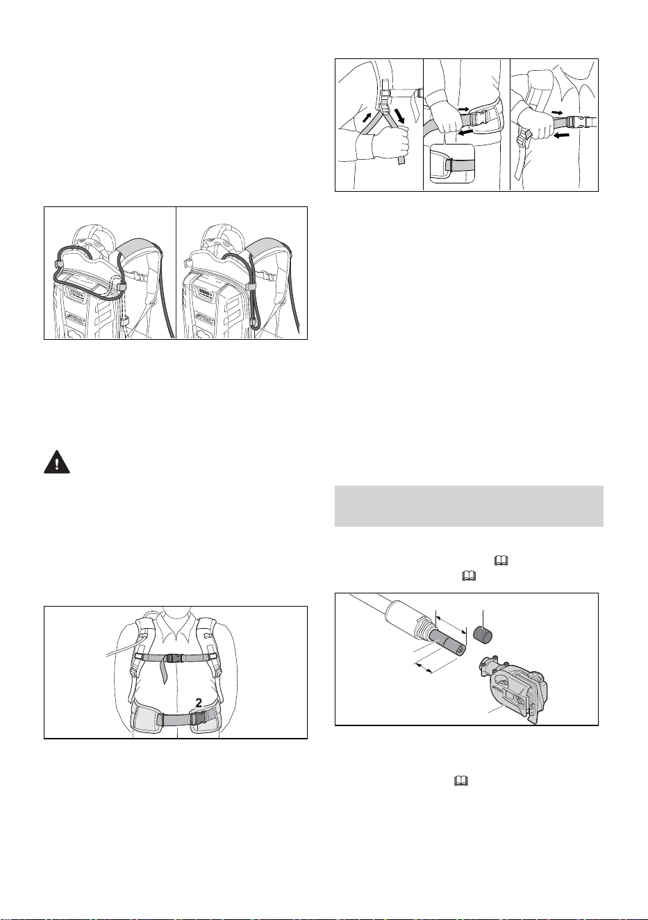
► Run the connection cord through the
guides on the shoulder strap (Illustration A), or
along the back plate (Illustration B). Secure
the connecting cord to the backpack frame
with the hook and eye fasteners (1). Always
secure the connecting cord using the guide or
hook and eye fasteners on the side of the
body on which the power tool is held and con‐
trolled. Do not allow the connecting cord to
swing across your body or hang at your side.
0000-GXX-2803-A1
D
C
► If the lenght of the connecting cord is too long,
adjust the connecting cord by making a loop
around the top (Illustration C) or on the side
(Illustration D) of the backpack battery with the
hook and eye fasteners.
14.2 Putting on the Harness
WARNING
■ To reduce the risk of personal injury, the oper‐
ator must be able to remove the backpack bat‐
tery quickly in the event of an emergency. In
an emergency, open and remove the waist
belt and chest strap quickly before dropping
the battery to the ground.
To ensure a proper fit:
1
0000-GXX-7803-A0
► Put the backpack battery on your back.
► Fasten and adjust the waist belt (2) so that it
rests comfortably but securely on your hips.
► Fasten the chest strap (1) and adjust it so that
it fits comfortably but securely across your
chest.
0000-GXX-2815-A1
3
► Adjust the harness straps so that the back
padding fits firmly and securely against your
back.
► Thread the end of the waist belt through the
loop (3).
► To remove the harness, open the quick-
release fasteners on the waist belt and chest
strap and loosen the harness straps by lifting
the sliding adjusters.
To help reduce the risk of injury in the event of
an emergency, practice quickly opening the fas‐
teners on the waist belt and chest strap, loosen‐
ing the shoulder straps and removing the battery.
NOTICE
■ To avoid damage, ease the battery to the
ground when practicing. Do not allow the bat‐
tery to drop to the ground and do not throw it.
15 Assembling the Pole Pru‐
ner
15.1 Mounting the Gearbox
►
Switch off the pole pruner,
17.2.
►
Remove the battery, 16.2.
b
1
2
3
a
0000097972_001
► Remove the cap (1) from the square end of
the drive tube (2).
► Adjust the length of the drive tube to
a = 3.9 in. (10 cm),
19.1.
► Mark the drive tube at b = 2.4 in. (6 cm).
► Push the gearbox onto the drive tube up to the
mark b.
15 Assembling the Pole Pruner English
0458-698-8621-B 21
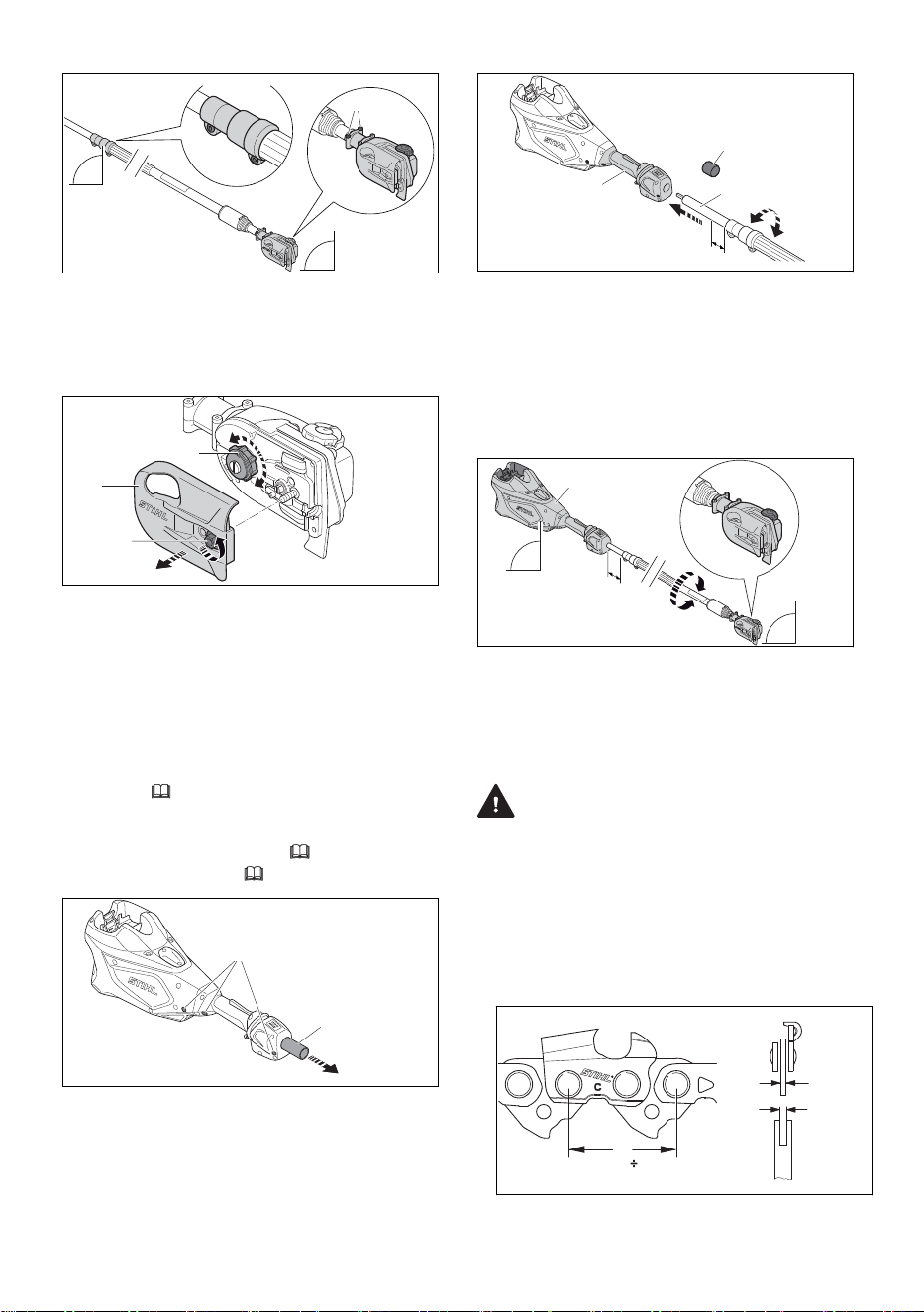
90°
4
3
90°
5
0000098531_001
► Align the clamping sleeve (4) and gearbox (3)
as shown. Make sure the clamping sleeve
screws are on the underside of the drive tube
and the oil cap on the gearbox is facing up.
► Tighten the screws (5).
7
6
8
0000098623_001
► If the gearbox cannot be pushed onto the
drive tube up to mark b:
► Remove the chain sprocket cover (6) by
turning the nut (7) counterclockwise.
► Turn the chain sprocket (8) until you can
push the gearbox to mark b on the drive
tube.
► Replace the chain sprocket cover and
secure the nut after mounting your bar and
chain,
15.6.1.
15.2 Mounting the Motor Housing
►
Switch off the pole pruner,
17.2.
►
Remove the battery, 16.2.
10
9
0000097324_001
► Loosen the screws (9).
► Remove the protective tubing (10).
11
12
2
0000097973_001
c
► Remove the cap (11) from the round end of
the drive tube (2).
► Rotate the drive tube until it can be inserted
into the opening in the control handle (12).
This may require rotating the drive shaft back
and forth until the two align.
► Push it in direction of the control handle until c
= 0.8 in. (2 cm).
13
c
3
90°
90°
0000098532_001
► Align the motor housing (13) and gearbox (3)
as shown. Make sure the battery opening and
oil cap are facing up.
► Tighten the screws (9).
15.3 Cutting Attachment
WARNING
■ If non-matching components are used, the cut‐
ting attachment will be damaged beyond
repair after a short period of operation, and the
chain could de-rail, resulting in serious or fatal
personal injury.
A cutting attachment consists of the chain, guide
bar and chain sprocket.
1
2
3
a
t = a 2
0000-GXX-1445-A0
–
The pitch (t) of the chain (1), must match
the pitch of the chain sprocket.
English 15 Assembling the Pole Pruner
22 0458-698-8621-B
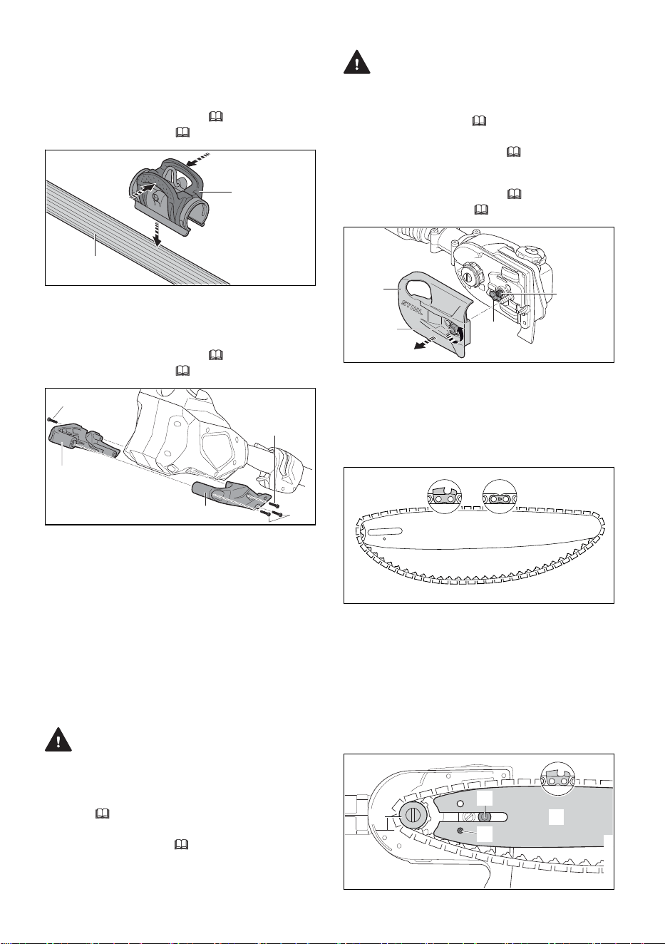
–
The drive link gauge (2) of the chain must
match the groove width of the guide bar (3).
15.4 Mounting the Harness Clip
►
Switch off the pole pruner,
17.2.
►
Remove the battery, 16.2.
1
2
0000097169_001
► Press the harness clip (1) together and place it
on the front handle (2).
15.5 Mounting the Machine Support
►
Switch off the pole pruner, 17.2.
►
Remove the battery, 16.2.
5
2
1
4
3
0000097173_001
► Position the left half of the machine support (1)
against the side of the motor housing.
► Insert screw (2).
► Position the right half of the machine sup‐
port (3) against the side of the motor housing.
► Insert screw (5).
► Insert and tighten screws (4).
► Tighten screws (2) and (5).
15.6 Mounting and Removing the
Guide Bar and Chain
15.6.1 Mounting the Guide Bar and Chain
WARNING
■ Make sure the battery is removed before start‐
ing assembly. Never operate your pole pruner
without a properly mounted guide bar and
chain,
6.5. Use only guide bar and chain
combinations expressly recommended or
approved by STIHL, 6.4.
WARNING
■ The chain has many sharp cutters. If they con‐
tact your flesh, they will cut you, even if the
chain is not moving, 6.4. Always wear
heavy-duty work gloves when mounting or oth‐
erwise handling the chain,
6.3.
To mount the guide bar and chain:
►
Switch off the pole pruner, 17.2.
►
Remove the battery, 16.2.
1
2
3
4
0000097170_001
► Turn the nut (1) counterclockwise until the
chain sprocket cover (2) can be removed.
► Remove the chain sprocket cover.
► Turn the side chain tensioner (3) counter-
clockwise until the tensioning gear (4) sits
flush against the housing.
0000-GXX-2954-A0
► Position the chain in the groove of the guide
bar, starting at the tip.
► Make sure that the cutters in the groove on the
top side of the guide bar face the tip of the bar.
STIHL chains are manufactured with arrows
on the tie straps to help the operator deter‐
mine the proper direction of the chain. Arrows
on the tie straps on the top of the bar must
point toward the bar tip.
6
7
5
8
0000097171_001
15 Assembling the Pole Pruner English
0458-698-8621-B 23
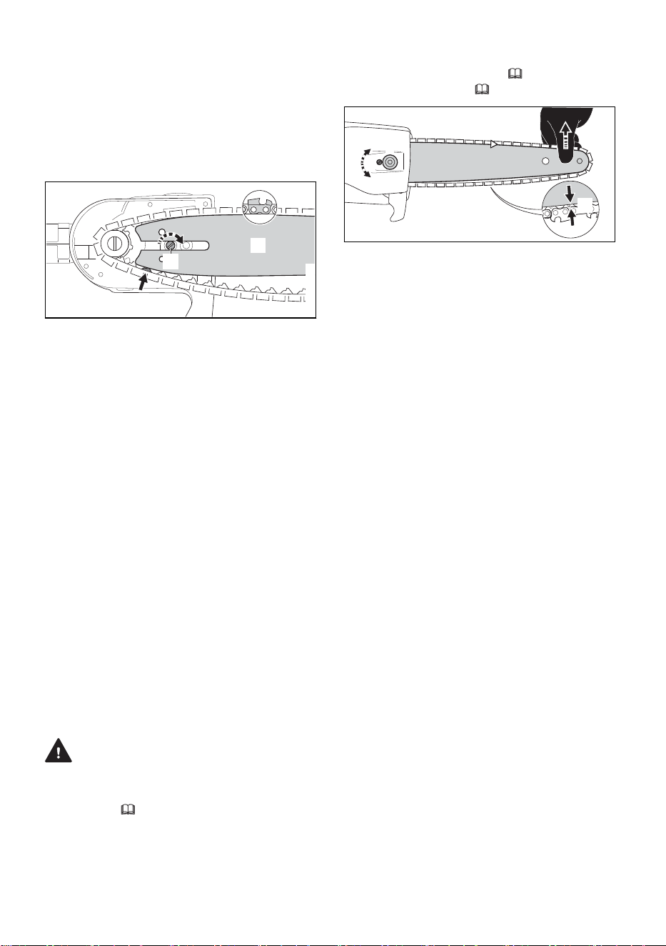
► Point the guide bar tip away from the chain
sprocket (7).
► Place the chain around the chain sprocket.
► Slide the guide bar (6) over the collar
screw (5). The head of the collar screw must
protrude into the oblong hole.
► Fit the pin of the tensioning gear in the hole (8)
of the guide bar.
0000097172_001
6
3
► Direct the drive links into the groove of the
guide bar (6, arrow) while turning the side
chain tensioner (3) clockwise until it stops.
The guide bar and chain must be firmly and
securely mounted on the pole pruner.
► Fit the sprocket cover on the pole pruner so
that it is flush with the housing.
► Turn the nut clockwise until the chain sprocket
cover is firmly attached to the pole pruner.
15.6.2 Removing the Guide Bar and Chain
► Unscrew the nut securing the chain sprocket
cover.
► Remove the chain sprocket cover.
► Turn the side chain tensioner counterclock‐
wise until it stops and the chain is loose.
► Remove the guide bar and chain.
NOTICE
■ The top and bottom of the guide bar are sym‐
metrical, and the bar may be mounted with the
printing facing up or down. Flipping the guide
bar each time the chain is sharpened or
changed will help reduce uneven wear and
improve its service life.
15.7 Tensioning the Chain
WARNING
■ To reduce the risk of severe personal injury
from chain derailment, check chain tension
frequently, 6.5. At operating temperatures,
the chain stretches and sags. New chain tends
to stretch more than used chain. Tension the
chain so that the drive links cannot come out
of the groove on the underside of the guide
bar.
To properly tension the chain:
►
Switch off the pole pruner, 17.2.
►
Remove the battery, 16.2.
0000-GXX-4761-A1
a
2
1
► Loosen the nut (1).
► Lift the guide bar tip.
► Turn the side chain tensioner (2) clockwise to
tighten the chain.
The chain is properly adjusted when the dis‐
tance between the underside of the guide bar
and the chain (a) is between 0.04 in. (1 mm)
and 0.08 in. (2 mm) and can still be pulled
easily along the bar by hand. Always wear
gloves when handling the chain.
► If the chain cannot be moved along the guide
bar, it is too tight.
–
Reduce the tension by turning the side
chain tensioner counterclockwise until the
chain can move freely along the guide bar.
–
Ensure that the drive links remain in the
groove and that the distance between the
underside of the guide bar and the chain (a)
is between 0.04 in. (1 mm) and 0.08 in.
(2 mm).
► Once the chain is properly tensioned, lift the
guide bar tip and tighten the nut to secure the
chain sprocket cover.
► Finally, ensure that the distance between the
underside of the guide bar and the chain (a) is
between 0.04 in. (1 mm) and 0.08 in. (2 mm).
NOTICE
■ Always release tension on the chain after fin‐
ishing work. The chain contracts as it cools
down. If it is not slackened, it can damage the
drive shaft and bearings. Properly re-tension
the chain before using the pole pruner again.
English 15 Assembling the Pole Pruner
24 0458-698-8621-B
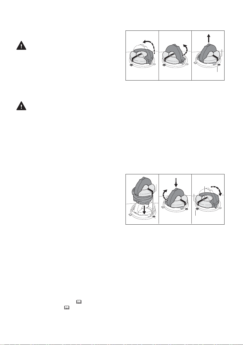
15.8 Lubricating the Saw Chain and
Guide Bar
15.8.1 Bar and Chain Lubricant
WARNING
■ Never operate your pole pruner without bar
and chain lubrication. If the chain runs dry, the
cutting attachment will be damaged beyond
repair within a very short time. A damaged
chain may break, resulting in severe or fatal
personal injury. Always check chain lubrication
and the oil level in the tank before starting
work and periodically during work.
WARNING
■ Never use waste oil to lubricate your saw
chain and guide bar. Repeated contact with
waste oil can cause skin cancer. Moreover,
waste oil is environmentally harmful.
Bar and chain oil lubricates and cools the rotat‐
ing saw chain. The service life of the chain and
guide bar depends on the quality of the lubricant.
It is therefore essential to use only a specially
formulated chain lubricant.
► For automatic and reliable lubrication of the
chain and guide bar, use only an environmen‐
tally compatible quality chain and bar lubri‐
cant. STIHL recommends using rapidly biode‐
gradable STIHL BioPlus.
NOTICE
■ Biodegradable chain oil must be resistant to
aging, since it will otherwise quickly turn to
resin. This results in hard deposits that are dif‐
ficult to remove, especially in the area of the
chain drive and chain. It may even cause the
oil pump to seize.
NOTICE
■ Waste oil does not have the necessary lubri‐
cating properties and is unsuitable for chain
lubrication.
15.8.2 Filling the Chain Oil Tank
Opening and Filling the Chain Oil Tank
To fill the chain oil tank:
►
Switch off the pole pruner,
17.2.
►
Remove the battery, 16.2.
► Position the pole pruner on a level surface
with the oil filler cap facing upwards.
► Clean the area around the oil filler cap with a
slightly dampened cloth.
0000-GXX-2930-A1
123
4
5
► Flip up the grip and press the cap down
firmly (1).
► Turn the cap slowly counter-clockwise (2) to
the open position (3). In the open position, the
exterior positioning mark (4) on the cap will
line up with the symbol (5) on the chain oil
tank housing
► Remove the cap and fill the tank with bar and
chain oil.
► Take care not to spill bar and chain oil while
refilling the tank.
► Do not overfill the tank. Leave approximately
0.5 in. (13 mm) of air space.
Closing
To close the tank:
2
3
1
0000-GXX-2931-A1
1
4
► Raise the grip on the top of the cap until it is
upright at a 90° angle. Insert the cap in the
chain oil tank opening with the exterior posi‐
tioning mark (1) lined up with the open sym‐
bol (2) on the chain oil tank housing.
► Using the grip, press the cap down firmly while
turning it clockwise to the closed position
(approximately 1/4 turn). In the closed posi‐
tion, the interior (4) and exterior (1) positioning
marks will align with the closed symbol (3) on
the chain oil tank housing.
► Fold the grip flush with the top of the cap and
check for tightness.
► If the grip does not lie completely flush with
the cap or the detent on the grip does not fit in
the corresponding recess in the tank opening,
or if the cap is loose, the cap is not properly
seated and you must repeat the above steps.
15 Assembling the Pole Pruner English
0458-698-8621-B 25
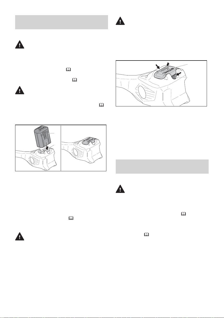
16 Inserting and Removing
the Battery
16.1 Inserting the Battery
WARNING
■ To reduce the risk of personal injury or prop‐
erty damage from fire or electric shock, never
use a malfunctioning, damaged, cracked, leak‐
ing or deformed battery,
8. Never charge,
use or store the battery outside the specified
ambient temperature limits, 26.6.
WARNING
■ To reduce the risk of unintended activation,
never store the battery in the pole pruner,
9.1.
To insert the battery:
1
2
0000097033-001
► Insert the battery (1) into the battery compart‐
ment (2) until it stops.
The battery is properly inserted when you hear
an audible click. In this position, there is elec‐
trical contact between the battery and the pole
pruner.
Since a new battery is not fully charged, STIHL
recommends that you fully charge the battery
before using it the first time,
11.
16.2 Removing the Battery
WARNING
■ To reduce the risk of severe personal injury
from unintended activation, always remove the
battery before assembling, transporting,
adjusting, cleaning, servicing, maintaining or
storing the pole pruner, and any other time it is
not in use.
WARNING
■ Use care when ejecting the battery to prevent
it from falling and causing personal injury or
property damage.
To remove the battery:
► Release the trigger switch.
2
1
0000097034-001
► Compress the locking levers (1) to eject the
battery (2) from the battery compartment.
NOTICE
■ Avoid exposing the battery to excessive heat
or prolonged periods of direct sunlight. Use or
storage outside the recommended ambient
temperature range can reduce the perform‐
ance of the battery.
17 Switching the Pole Pruner
On and Off
17.1 Switching On
WARNING
■ Never operate your pole pruner if it is modi‐
fied, damaged, improperly adjusted or main‐
tained, not completely and securely assem‐
bled or not functioning properly,
6.4. To
reduce the risk of personal injury, always wear
proper clothing and protective apparel, includ‐
ing proper eye protection, when operating your
pole pruner,
6.3.
Before switching on:
► Make sure other persons are out of the gen‐
eral work area.
► Make sure you have a secure and firm footing.
► Stand upright.
► Always hold and operate the pole pruner with
one hand firmly on the control handle and with
the other hand firmly on the front handle.
To switch the pole pruner on:
English 16 Inserting and Removing the Battery
26 0458-698-8621-B
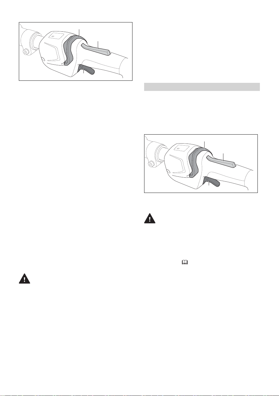
3
1
2
0000097175_001
► Depress and hold the trigger switch lock‐
out (1).
► While holding the trigger switch lockout, push
the retaining latch (2) forward with your thumb
and release it.
The LED glows.
► Squeeze the trigger switch (3) with your index
finger.
The saw chain will start rotating.
You can also unlock the trigger switch by push‐
ing the retaining latch forward and depressing
the trigger switch lockout within 5 seconds (as
long as the LED is flashing). Squeeze the trigger
switch with your index finger to start the saw
chain.
The motor will not switch on unless the trigger
switch lockout is depressed, the retaining latch
has been pushed forward and the trigger switch
has been pressed.
If the trigger switch and the trigger switch lockout
are released, the LED will remain flashing for
approximately 5 seconds. As long as the LED is
flashing, the pole pruner can again be switched
on without pushing the retaining latch forward.
The further the trigger switch is squeezed, the
faster the saw chain will rotate.
17.2 Switching Off
WARNING
■ The saw chain will continue to rotate for a
short while after the trigger switch is released.
To avoid serious or fatal injury, avoid contact
with the moving saw chain. To reduce the risk
of personal injury from unintended activation
or unauthorized use, switch off the motor,
ensure the chain has stopped and remove the
battery before transporting the pole pruner or
putting it down.
To switch the pole pruner off:
► Release the trigger switch and trigger switch
lockout so that the trigger switch springs back
to the locked position. In the locked position,
activation of the trigger switch is blocked by
the trigger switch lockout. Activation of the
pole pruner is also electronically blocked by
the retaining latch once the LED stop flashing
(after approximately 1 second).
The saw chain will continue to move for a short
time after the trigger switch is released. Take
care to avoid contact after releasing the trigger
switch and when setting down the pole pruner.
18 Checking the Pole Pruner
18.1 Testing the Controls
Before starting work, confirm that the trigger
switch lockout (1), retaining latch (2) and trigger
switch (3) are undamaged and functioning prop‐
erly.
3
1
2
0000097175_001
Trigger Switch Lockout (1), Retaining Latch (2)
and Trigger Switch (3)
WARNING
■ To reduce the risk of serious or fatal injuries,
keep hands, feet and other parts of the body
away from the chain. Do not touch the saw
chain while the battery is inserted. Never
touch moving chain with your hand or any part
of your body,
6.5.2. Keep bystanders at
least 50 ft. (15 m) out of the area while testing
the controls.
To test the controls:
► Remove the battery.
► Attempt to depress the trigger switch.
If the trigger switch can be depressed without
first unlocking the retaining latch, take the pole
pruner to an authorized STIHL servicing
dealer to be repaired before use.
► Press down on the trigger switch lockout and
push the retaining latch forward. Make sure
they move freely and spring back into place
when released.
► Insert the battery.
18 Checking the Pole Pruner English
0458-698-8621-B 27
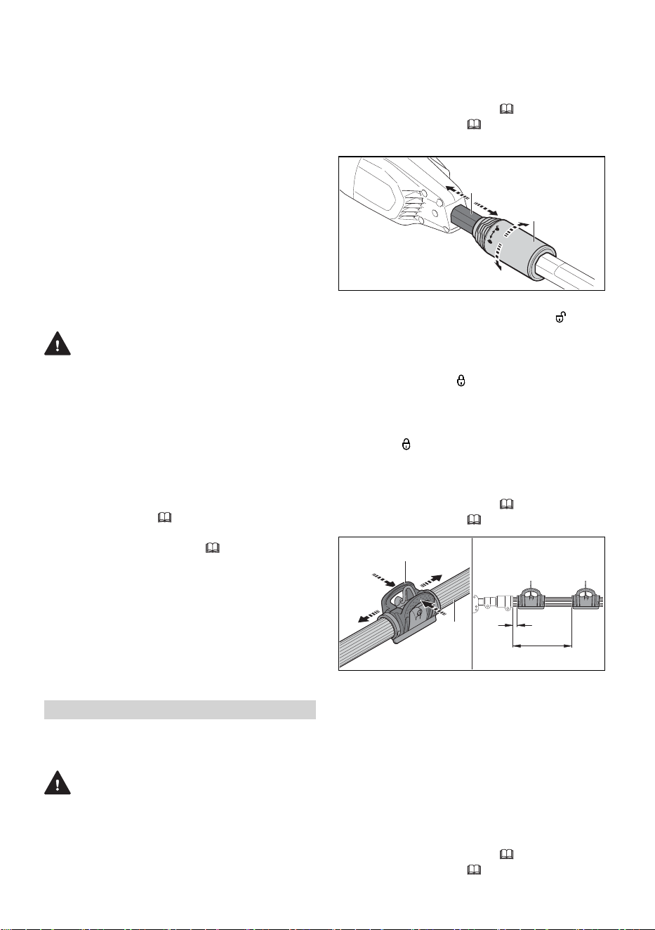
► Hold the pole pruner firmly with one hand on
the control handle and with the other hand
firmly on the front handle. Depress and hold
the trigger switch lockout, push the retaining
latch forward with your thumb and squeeze
the trigger switch with your index finger.
The pole pruner should switch on. If it does
not, take the pole pruner to an authorized
STIHL servicing dealer to be repaired before
use.
► Release the trigger switch.
The pole pruner should switch off.
If the pole pruner does not switch off after you
release the trigger switch, remove the battery
and take the pole pruner to an authorized
STIHL servicing dealer to be repaired before
use.
18.2 Testing Chain Lubrication
WARNING
■ Never operate your pole pruner without bar
and chain lubrication. If the chain runs dry, the
cutting attachment will be damaged beyond
repair within a very short time. A damaged
chain may break, resulting in severe or fatal
personal injury. Always check chain lubrication
and the oil level in the tank before starting
work and periodically during work.
To confirm that the chain oil is flowing properly:
►
Insert the battery,
16.1.
► Point the guide bar toward a bright surface.
►
Switch on the pole pruner, 17.1.
The chain should throw off a small amount of
oil.
If the chain oil cannot be seen, check the oil
level and refill the tank as necessary.
► Test the chain lubrication again.
► If chain lubrication oil is still not visible, the
lubrication mechanism is not functioning. Take
the pole pruner to an authorized STIHL servic‐
ing dealer to be repaired before use.
19 During Operation
19.1 Adjusting the Length of the
Drive Tube
WARNING
■ To reduce the risk of injury from loss of con‐
trol, ensure that the drive tube is properly
adjusted and engaged in the locked position
before starting work.
The length of the drive tube can be adjusted to
suit the height and reach of the operator.
To adjust the length of the drive tube:
►
Switch off the pole pruner,
17.2.
►
Remove the battery, 16.2.
► Hold the drive tube firmly.
2
1
0000097146_001
► Unlock the drive tube (2) by turning the clamp‐
ing nut (1) a half turn in the direction .
► Adjust the drive tube length by sliding it into
the desired position.
► Lock the drive tube by turning the clamping
nut in the direction and tightening it.
► Confirm that the drive tube is fixed in place.
► If the drive tube still can be moved: Lock the
drive tube by turning the clamping nut in the
direction and tightening it until the drive tube
is fixed in place.
19.2 Align the Harness Clip
►
Switch off the pole pruner,
17.2.
►
Remove the battery, 16.2.
a
b
2
1
0000097174_001
► Press the harness clip (1) together and move
it on the grip hose (2) to achieve the following
dimensions:
–
If the drive tube is fully retracted: a = 6 in.
(15 cm).
–
If the drive tube is fully extended: b = 20 in.
(50 cm).
19.3 Putting on and Adjusting the
Shoulder Strap
To fit and adjust the harness:
►
Switch off the pole pruner,
17.2.
►
Remove the battery, 16.2.
English 19 During Operation
28 0458-698-8621-B
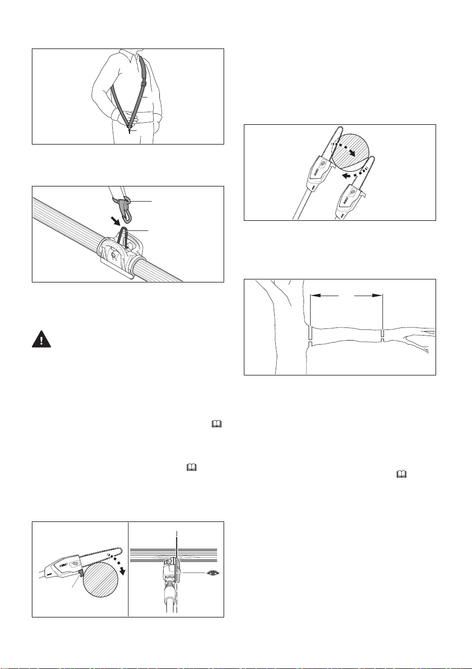
► Put the shoulder strap over your shoulder.
2
1
0000-GXX-2990-A0
► Adjust the length of the shoulder strap (1) so
that the carabiner (2) is about a hand’s width
below the top of your hip.
1
2
0000097177_001
► Attach the carabiner (1) to the harness clip (2)
on the pole pruner.
19.4 Limbing
WARNING
■ To reduce the risk of severe or even fatal
injury from falling objects:
–
Do not cut vertically above your body. Hold
the pole pruner at an angle of not more than
60° from the horizontal level. Objects may
fall in unexpected directions. Do not stand
directly underneath the limb being cut,
6.5.4.
–
Watch for falling limbs. As soon as the lim‐
bed branch starts to fall, step aside and
keep a sufficient distance away, 6.5.4.
► To allow branches to free fall, always cut the
lower branches first.
Cross-cut
1
0000085007_003
► Position the hook (1) against the branch.
The limbing sight helps the operator position
the bar and chain for the cut.
► Cut the branch at full throttle with the bottom
side of the guide bar, keeping the tip of the bar
free of other limbs, the ground and any leafy
materials.
Relieving Cut
1
2
0000-GXX-4765-A1
► If the limb is under tension: Make a relieving
cut (1) on the underside and then perform the
cross-cut (2) from the tension side.
Cutting thick branches
a
B
A
1
2
2
1
0000097743_001
► Shorten the branch by performing a relieving
cut (1) and then a cross-cut (2) at cutting point
(A) at a distance a = 8 in. (20 cm) from where
the flush-cut will be made (B).
► Carry out the flush-cut, starting with a relieving
cut (1) and finishing with a cross-cut (2) at cut‐
ting point (B).
For optimum performance, observe the recom‐
mended ambient temperature ranges,
26.7.
19 During Operation English
0458-698-8621-B 29
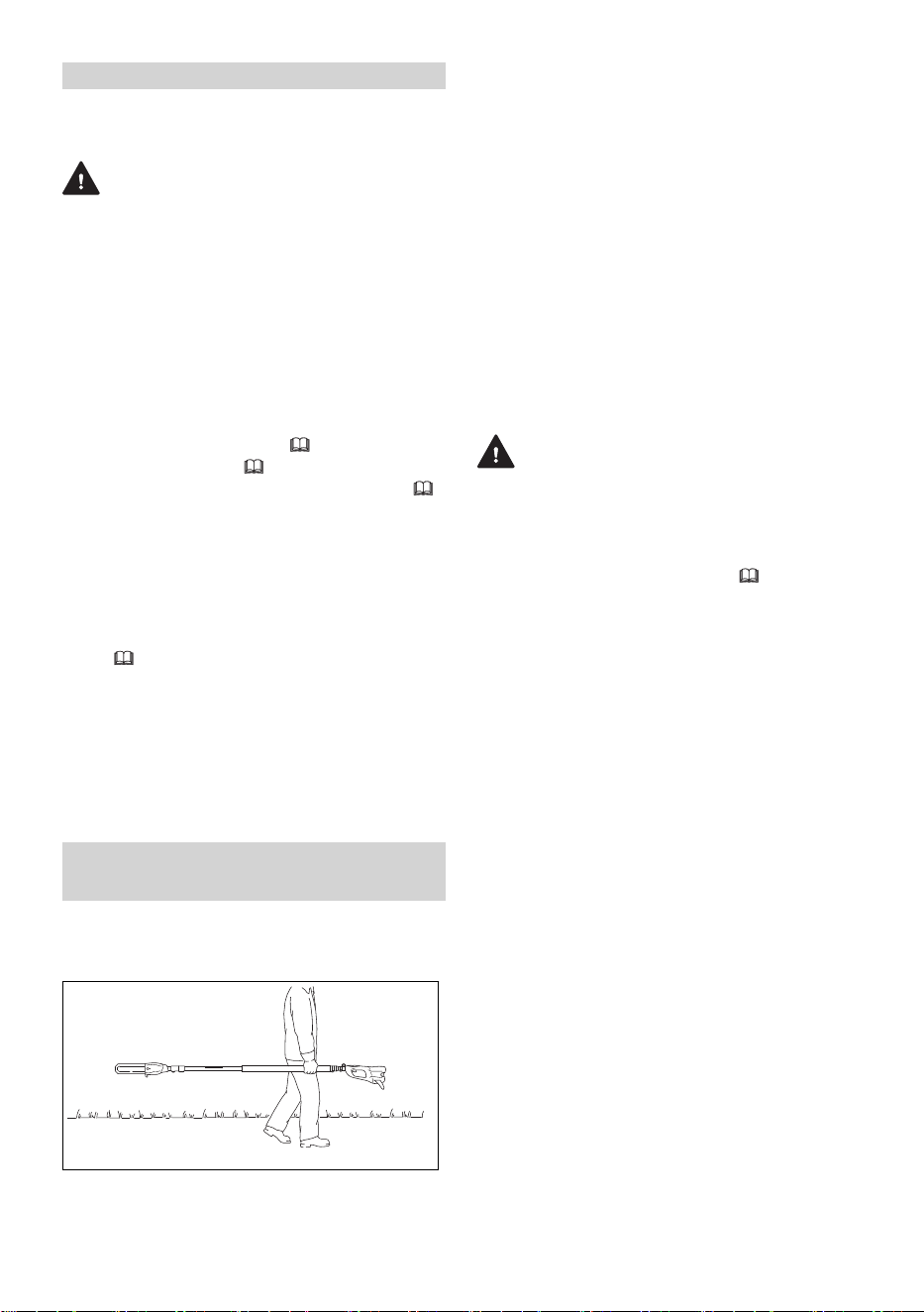
20 After Finishing Work
20.1 Preparing for Transportation or
Storage
WARNING
■ To reduce the risk of personal injury from unin‐
tended activation or unauthorized use, switch
off the pole pruner and remove the battery
before transporting the pole pruner or putting it
down. To reduce the risk of injuries from the
sharp cutters on the chain, always cover the
guide bar with the chain scabbard before
transporting or storing the pole pruner.
To prepare the pole pruner for transportation or
storage:
►
Switch off the pole pruner, 17.2.
►
Remove the battery, 16.2.
►
Adjust the drive tube to its shortest length,
19.1
► Loosen the chain.
► Slide a chain scabbard over the guide bar so
that it covers the entire guide bar.
► If the battery or pole pruner became damp or
wet during operation, allow them to dry sepa‐
rately and completely before charging or stor‐
ing,
26.7.
► Before using the pole pruner, remember to re-
tension the chain.
NOTICE
■ The chain contracts as it cools down. Failing
to loosen the chain after finishing work can
damage the drive shaft and bearings.
21 Transporting the Pole Pru‐
ner and Battery
21.1 Pole Pruner
When transporting the pole pruner:
0000097742_001
► Slide a chain scabbard over the guide bar so
that it covers the entire guide bar.
► When transporting the pole pruner by hand,
hold the drive tube in a manner that balances
the pole pruner horizontally. Keep the cutting
attachment behind you.
► When transporting the pole pruner in a vehi‐
cle, cover the guide bar with a chain scabbard.
Secure and position the pole pruner to prevent
turnover, impact and damage.
Your pole pruner comes standard with a chain
scabbard that matches the cutting attachment. If
you use guide bars of different lengths on the
pole pruner, the length of the chain scabbard
must be matched to the guide bar to reduce the
risk of injury. It should cover the full length of the
guide bar.
21.2 Battery
WARNING
■ To reduce the risk of a short circuit, which
could lead to electric shock, fire and explosion,
never transport the battery with small metal
objects capable of conducting electricity (e.g.,
paper clips, nails, coins, keys),
8.
When transporting the battery:
► Secure the battery in a container against
impact or damage. Never transport the battery
with small metal objects capable of conducting
electricity (e.g., paper clips, nails, coins, keys).
► If you are transporting the battery in a vehicle,
secure it and its container to prevent turnover,
impact and damage.
STIHL batteries comply with the requirements
set forth in UN-Manual of Tests and Criteria, Part
III, Subsection 38.3.
Commercial air, vessel and ground transporta‐
tion of lithium ion cells and batteries is regulated.
The battery is classified as a UN 3480, Class 9,
packaging group II product. Shipping it, either as
a complete tool or the battery, requires compli‐
ance with all applicable shipping regulations.
Check with the ground, vessel, air cargo or pas‐
senger airline to determine if transport is prohibi‐
ted or subject to restrictions or exemptions prior
to shipping or travel.
Normally, no further conditions have to be met by
the user in order to transport STIHL batteries by
road to the power tool's operating site. Check
and comply with any special regulations that may
apply to your situation.
For further information please go to www.stih‐
lusa.com/battery-transportation-safety.
English 20 After Finishing Work
30 0458-698-8621-B
22 Storing the Pole Pruner
and Battery
22.1 Pole Pruner
WARNING
■ Store the pole pruner indoors in a dry, secure
place that cannot be accessed by children or
other unauthorized users, 6.4. Never store
the battery in the pole pruner. Improper stor‐
age can result in unauthorized use and dam‐
age to the pole pruner,
6.4.
When storing the pole pruner for thirty days or
longer:
► Remove any wood chips or debris from the
battery compartment.
► Remove the chain and guide bar.
► Clean and spray the guide bar with a resin sol‐
vent, such as STIHL Resin Remover and
Lubricant.
►
Clean the pole pruner,
23.1.
►
Fill up the chain oil tank, 15.8.2.
► Secure and position the pole pruner to prevent
turnover, impact and damage.
► Store the pole pruner indoors in a dry and
secure location, out of the reach of children
and other unauthorized persons.
22.2 Battery
WARNING
■ To reduce the risk of a short circuit, which
could lead to electric shock, fire and explosion,
never store the battery with small metal
objects capable of conducting electricity (e.g.,
paper clips, nails, coins, keys),
8. If the bat‐
tery is damp or wet, allow it to dry thoroughly
before storing, 8.
WARNING
■ Extreme temperatures can damage the battery
and may also cause the battery to generate
heat, rupture, leak, ignite or explode, resulting
in severe or fatal personal injury or property
damage. Never charge, use or store the bat‐
tery outside the specified ambient temperature
limits,
26.6.
To properly store the battery:
► Remove the battery from the pole pruner.
► When storing the battery, maintain a charge of
40 % to 60 % for STIHL AP series batteries
and a charge of 30 % to 45 % for STIHL AR
series batteries (2 green LEDs).
► If storing the battery in the charger, disconnect
the charger from the outlet.
► Make sure the battery is dry and store it
indoors in a dry and secure location.
► Keep it out of the reach of children and other
unauthorized persons.
► Protect the battery against dampness and cor‐
rosive agents such as garden chemicals and
de-icing salts.
► Protect the battery from exposure to conduc‐
tive liquids such as salt water.
► For maximum battery life, store the battery at
an ambient temperature between 50 °F and
68 °F (10 °C and 20 °C) with a charge
between 40 % and 60 % for STIHL AP series
batteries and a charge of 30 % to 45 % for
STIHL AR series batteries (2 green LEDs).
► Do not leave spare batteries unused. Use
them in rotation.
NOTICE
■ A battery that is not stored properly may expe‐
rience deep discharge, which can result in per‐
manent damage. To avoid deep discharge:
–
Remove the battery from the pole pruner
after finishing work.
–
For maximum battery life, store the battery
with a charge between 40 % and 60 % for
STIHL AP series batteries and a charge of
30 % to 45 % for STIHL AR series batteries
(2 green LEDs).
–
If storing the battery in the charger, discon‐
nect the charger from the outlet.
–
For maximum battery life, store the battery
at an ambient temperature between 50 °F
and 68 °F (10 °C and 20 °C).
23 Cleaning
23.1 Cleaning the Pole Pruner and
Battery
WARNING
■ To reduce the risk of personal injury from unin‐
tended activation, remove the battery before
carrying out any cleaning work, 9.
To clean the pole pruner and battery:
► Clean the pole pruner's polymer components
with a slightly dampened cloth. Do not use
detergents or solvents. They may damage the
polymer components.
22 Storing the Pole Pruner and Battery English
0458-698-8621-B 31
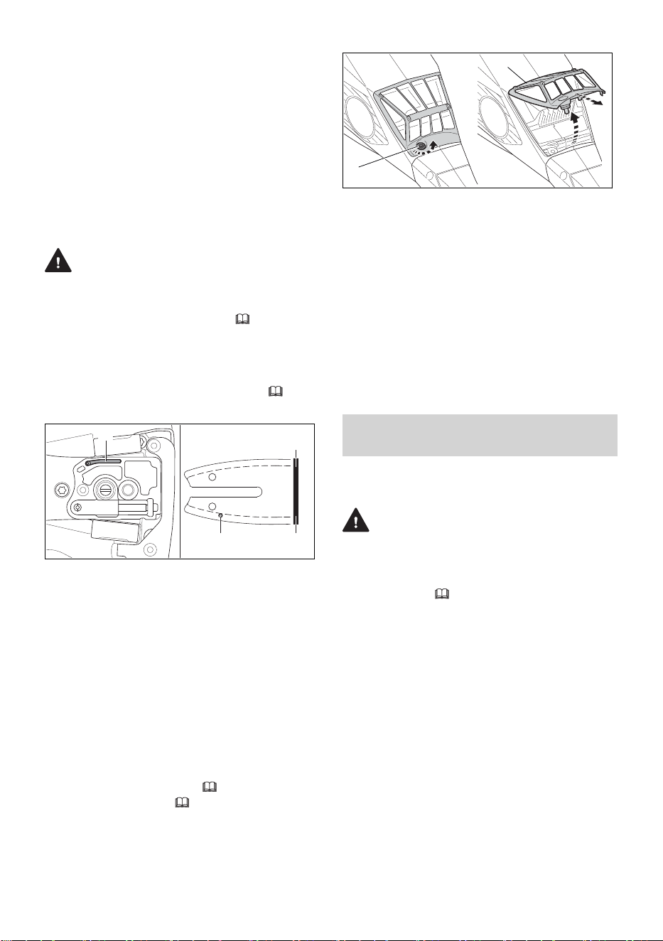
► Remove the sprocket cover and clean the
area around the chain sprocket with a slightly
dampened cloth or resin solvent, such as
STIHL Resin Remover & Lubricant.
► Do not use a pressure washer to clean the
pole pruner or otherwise spray it with water or
other liquids.
► Keep the battery housing and guides free from
foreign matter and clean as necessary with a
soft brush or soft, dry cloth.
23.2 Cleaning the Guide Bar and
Saw Chain
WARNING
■ To reduce the risk of personal injury from unin‐
tended activation, remove the battery before
carrying out any cleaning work, 9. To help
prevent injuries, always wear heavy-duty work
gloves when handling the chain.
To properly clean the guide bar and chain:
►
Remove the guide bar and the chain,
15.6.2.
3
1
2
3
0000097134_001
► Clean the oil outlet duct (1), oil inlet bore (2)
and groove (3) with a brush, a slightly damp‐
ened cloth or resin solvent, such as STIHL
Resin Remover & Lubricant. Do not use deter‐
gents.
► Clean the chain with a brush, a slightly damp‐
ened cloth or resin solvent. Do not use deter‐
gents.
► Do not use a pressure washer to clean the
guide bar or chain or otherwise spray them
with water or other liquids.
23.3 Cleaning the Air Filter
To clean the air filter:
►
Switch off the power tool,
17.2.
►
Remove the battery, 16.2.
0000097125-001
1
2
► Clean the area around the air filter (2) with a
damp cloth or soft brush.
► Turn the screw (1) counterclockwise until the
air filter can be removed.
► Remove the air filter by lifting it up and pulling
it off.
► Rinse away coarse dirt from the outside of the
air filter under running water. Never spray the
air filter with a pressure washer.
► If the air filter is damaged, replace it.
► Allow the air filter to air dry.
► After the air filter has dried thoroughly, push it
into place by hand.
► Tighten the screw.
24 Inspection and Mainte‐
nance
24.1 Inspecting and Maintaining the
Pole Pruner
WARNING
■ To reduce the risk of personal injury from unin‐
tended activation, remove the battery before
inspecting the pole pruner or carrying out any
maintenance,
9.
Proper maintenance of the pole pruner includes
the following activities:
► Cleaning the air filter every 50 hours of opera‐
tion.
► Inspecting the chain sprocket periodically and
having a worn chain sprocket replaced by an
authorized STIHL servicing dealer.
► Inspecting the guide bar for proper groove
depth and spread and replacing the guide bar
if it shows signs of excessive wear or damage.
► Periodically sharpening the chain, maintaining
the depth limiting guides at the appropriate
height and replacing the saw chain when indi‐
cated by the relevant wear marks or when the
chain is damaged or shows signs of excessive
wear.
English 24 Inspection and Maintenance
32 0458-698-8621-B
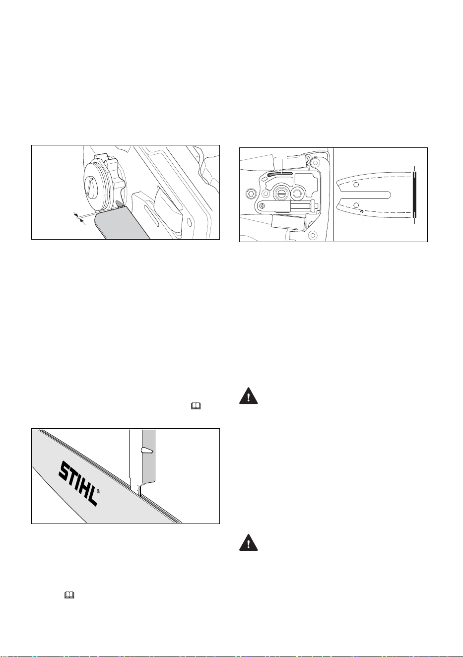
► Having worn, missing or damaged safety
labels replaced by an authorized STIHL serv‐
icing dealer.
24.2 Inspecting and Maintaining the
Chain Sprocket
► Switch off the pole pruner and remove the bat‐
tery.
► Remove the chain sprocket cover, saw chain
and guide bar.
a
0000097176_001
► Check the chain sprocket cover for wear
marks.
► If the wear marks are deeper than
a = 0.020 in. (0.5 mm), have the chain
sprocket replaced.
STIHL recommends using genuine STIHL chain
sprockets.
Alternating between two chains helps reduce
wear to the chain sprocket.
24.3 Inspecting and Maintaining the
Guide Bar
► Switch off the pole pruner and remove the bat‐
tery.
►
Remove the guide bar and saw chain,
15.6.2.
0000-GXX-1217-A0
► Measure the depth of the guide bar groove in
the area with the greatest wear using the
measuring tool on the file gauge (special
accessory, not included).
► Replace the guide bar if the measured depth
is less than the required minimum depths sta‐
ted in 26.4.
► Check the spread of the guide bar groove with
the measuring tool on the file gauge.
► Replace the guide bar if the groove is nar‐
rowed, spread or shows other signs of sub‐
stantial wear or damage.
To maintain the guide bar:
► Flip the guide bar after each sharpening and
each time the chain is changed. This will help
reduce uneven wear. There is no "top" or "bot‐
tom" of the bar. It may be used in either orien‐
tation, even though the printing on the bar may
be upside down.
3
1
2
3
0000097134_001
► Clean the oil outlet duct (1), oil inlet bore (2)
and groove (3) with a brush, a slightly damp‐
ened cloth or resin solvent, such as STIHL
Resin Remover & Lubricant. Do not use deter‐
gents.
► Periodically remove any metal burrs that
develop along the guide bar with a flat file or a
STIHL guide bar dressing tool.
► Replace the guide bar if the burrs cannot be
filed or if the guide bar becomes damaged.
24.4 Inspecting, Maintaining and
Sharpening the Saw Chain
WARNING
■ An improperly sharpened chain can increase
the risk of kickback and other reactive forces,
resulting in severe personal injury or death.
For example, depth gauges that are too low or
cutters that are filed incorrectly can increase
the kickback tendency of the pole pruner and
can increase kickback forces, making it more
difficult to control the pole pruner. Always
review and follow the sharpening angles and
dimensions recommended by STIHL when
checking or sharpening the chain.
WARNING
■ Never use a dull or damaged chain. This leads
to increased physical strain, increased vibra‐
tion load, unsatisfactory cutting results and
increased wear. If the chips from cutting are
fine, more like saw dust than wood chips, the
chain likely is dull.
24 Inspection and Maintenance English
0458-698-8621-B 33
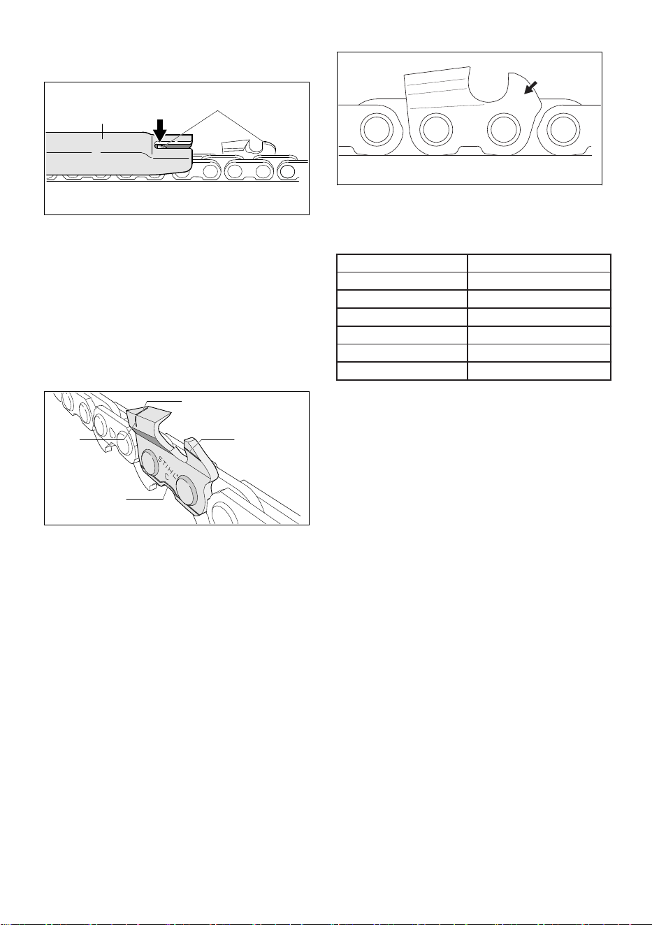
► Switch off the pole pruner and remove the bat‐
tery.
1
0000-GXX-1218-A0
2
► Check the height of the depth gauge (1) with a
STIHL file gauge (2) matching the pitch of the
chain.
► If the depth gauge protrudes higher than the
file gauge, file the depth gauge to the appro‐
priate height.
► Work carefully. Filing the depth gauges too
low will increase reactive forces. If the depth
gauges have been filed too low, have the
chain sharpened or replaced by an authorized
STIHL dealer.
0000-GXX-1372-A0
1
2
3
4
STIHL chain is manufactured with wear marks to
help the operator identify excessive wear. The
wear marks depicted above (1 - 4) must remain
visible.
► Replace the chain if any wear marks are no
longer visible.
► Check the 30° sharpening angle of the cutters
with a STIHL file gauge matching the pitch of
the chain.
► If the sharpening angle is incorrect, file the
cutters to a 30° angle.
► If you are unable to achieve the proper angle,
or suspect you have not achieved the proper
angle, have the chain sharpened by an author‐
ized STIHL servicing dealer.
An improperly filed chain can be very dangerous.
It can increase the potential for reactive forces,
including kickback, and also increase the magni‐
tude of those reactive forces.
a
0000-GXX-1446-A0
The chain pitch marking (a) is embossed in the
area of the depth gauge of each cutter.
The markings mean the following:
Marking (a) Saw Chain Pitch
1 1/4"
2 .325"
3 3/8"
4 .404"
6 3/8" PICCO
7 1/4" PICCO
To sharpen the chain:
► Switch off the pole pruner and remove the bat‐
tery.
► Select a chain file with a diameter matching
the pitch of the chain.
Other files are unsuitable and can result in
improperly filed chain, which can increase the
potential and force of kickback and other reac‐
tive forces.
► Clamp the guide bar if necessary to make fil‐
ing easier.
► Use a file holder.
File holders have markings that indicate the
proper sharpening angle.
► File all the cutters with an identical angle. Two
or three strokes of the file are usually sufficient
for simple resharpening. Remove a little mate‐
rial with each stroke.
Sharpening at varying or inconsistent angles
or heights can be very dangerous and may
result in rough or uneven running of the chain
and increased wear, even to the point of chain
breakage. It also can increase the tendency
and force of kickback and other reactive
forces.
English 24 Inspection and Maintenance
34 0458-698-8621-B
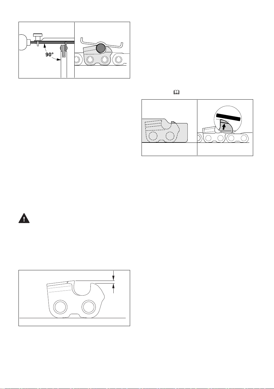
0000-GXX-1219-A0
► Guide the file horizontally at a right angle to
the side surface of the guide bar in accord‐
ance with the specified angle.
► File only from the inside of the cutter outward.
► Lift the file on the backstroke. The file only
sharpens on the forward stroke.
► Do not file tie straps or drive links.
► Periodically rotate the file in order to avoid
uneven wear.
► To remove a file burr from the cutter tooth, run
the cutter across a piece of hardwood.
► Check the sharpening angle with a file gauge.
All cutters must be of equal length and filed down
to the length of the shortest cutter. Otherwise,
the tendency and force of kickback and other
reactive forces will increase.
STIHL recommends having your chain sharp‐
ened by an authorized STIHL servicing dealer to
reduce the risk of severe or fatal injury from an
improperly sharpened chain.
WARNING
■ Depth gauges that are too low increase the
potential and force of kickback and other reac‐
tive forces, which can increase the risk of seri‐
ous personal injury. Always maintain the
proper distance between the depth gauge and
the top of the cutter (a).
a
0000-GXX-1447-A0
The depth gauge determines the depth to which
the cutter penetrates the wood and thus the chip
thickness.
A depth gauge that is too low will increase the
kickback tendency of the pole pruner and can
increase kickback forces.
A depth gauge that is too high will prevent the
cutter from entering the workpiece and will lead
to poor cutting performance. Always keep the
required distance between depth gauge and cut‐
ting edge (a),
26.5.
0000-GXX-1220-A1
To properly lower the depth gauge:
► Lay the appropriate file gauge for the chain
pitch on the chain and press it against the cut‐
ter to be checked. If the depth gauge pro‐
trudes past the file gauge, the depth gauge
must be filed down.
► File the depth gauge so that it is flush with the
top of the file gauge.
► Afterwards, remove the file gauge and file the
leading edge of the depth gauge parallel to the
service mark. When doing this, be careful not
to further lower the highest point of the depth
gauge.
► Lay the file gauge on the chain to check the
height of the file gauge. The highest point of
the depth gauge must be flush with the top of
the file gauge.
► After sharpening, clean the chain thoroughly,
removing any filings or grinding dust.
► Oil the chain thoroughly.
24 Inspection and Maintenance English
0458-698-8621-B 35

25 Troubleshooting Guide
25.1 Pole Pruner and Battery
Always remove the battery before carrying out any inspection, cleaning or maintenance.
Condition LEDs on
Battery
Possible Cause Remedy
Pole pruner does
not start when
switched on.
No electrical
contact between
pole pruner and
battery.
►
Remove the battery, 16.2.
► Visually check the electrical contacts in the bat‐
tery compartment and on the battery.
►
Reinsert the battery, 16.1.
1 LED
flashes
green.
STIHL AR
only: Addi‐
tionally, four
long beeps
are emitted.
Battery has low
charge.
►
Charge the battery, 11.
1 LED glows
red.
Battery too hot /
too cold.
► Allow the battery to warm up or cool down grad‐
ually at ambient temperatures of about 50 °F to
68 °F (10 °C to 20 °C).
4 LEDs flash
red.
STIHL AR
only: Addi‐
tionally, a
rapid suc‐
cession of
short beeps
is emitted.
Malfunction in
battery.
►
Remove the battery and reinsert it, 16.
►
Switch on the pole pruner, 17.1.
► If the LEDs continue to flash, do not attempt to
use.
The battery has a malfunction and must be
replaced.
3 LEDs glow
red.
Pole pruner too
hot.
► Allow the pole pruner to cool down.
3 LEDs flash
red.
Malfunction in
pole pruner.
►
Remove the battery and reinsert it, 16
►
Switch on the pole pruner, 17.1.
► If the LEDs still flash, do not attempt to use.
The pole pruner has a malfunction and must be
checked by a servicing dealer.
Pole pruner cuts
out during opera‐
tion.
1 LED glows
red.
Battery too hot /
too cold.
►
Remove the battery, 16.2.
► Allow the pole pruner and battery to cool down
gradually at ambient temperatures of about
50 °F to 68 °F (10 °C to 20 °C).
3 LEDs glow
red.
Pole pruner too
hot.
Run-time is too
short.
Battery not fully
charged.
►
Charge the battery, 11.
Useful life of bat‐
tery has been
reached or
exceeded.
► Have the battery checked by an authorized
STIHL servicing dealer.
During sawing,
the wood
smokes or smells
burnt.
The chain is dull
or improperly
sharpened.
►
Properly sharpen the chain, 24.4.
Working techni‐
que is improper
or the pole pru‐
ner is being mis-
used.
► Obtain instruction on proper working technique.
English 25 Troubleshooting Guide
36 0458-698-8621-B

Condition LEDs on
Battery
Possible Cause Remedy
Insufficient bar
and chain oil.
► Have the chain lubrication mechanism checked
by an authorized STIHL servicing dealer.
Battery is not
being charged
even though LED
on charger glows
green.
1 LED glows
red.
Battery too hot /
too cold.
► Allow the battery to warm up or cool down grad‐
ually at ambient temperatures of about 50 °F to
68 °F (10 °C to 20 °C).
► Read and follow the warnings and instructions in
your charger's manual. For optimum perform‐
ance, observe the recommended ambient tem‐
perature ranges, 26.7.
Battery cannot
be found with the
STIHL connected
App.
Bluetooth
®
inter‐
face at the bat‐
tery or at your
mobile device is
not turned on.
►
Activate the Bluetooth
®
interface at the battery
and at your mobile device, 13.1.
Distance
between the bat‐
tery and your
mobile device is
too large.
► Reduce the distance between the battery and
your mobile device, 26.2.
► If the battery still cannot be found with the
STIHL connected App: Contact an authorized
STIHL servicing dealer for assistance.
26 Specifications
26.1 STIHL HTA 135
–
Approved battery types:
–
STIHL AP series
–
STIHL AR series
–
Weight without battery: 15.0 lbs. (6.8 kg)
–
Maximum oil tank volume: 3.6 oz. (0.22 l)
For technical information regarding the
STIHL AP and AR series batteries, see the prod‐
uct information accompanying your battery.
For technical information regarding the
STIHL AL 101, 301, 301-4 and 501 series charg‐
ers, see the product information accompanying
your charger.
Batteries, chargers and other accessories sold
separately. Contact your authorized STIHL serv‐
icing dealer for pricing and availability.
26.2 STIHL AP Series Battery
Approved charger types: STIHL AL 101, AL 301,
AL 301-4, AL 501.
–
Battery technology: Lithium-Ion
–
Voltage: 36 V
–
Rated capacity in Ah
2
: See rating plate
–
Stored energy in Wh
3
: See rating plate
–
Weight in kg: See rating plate
–
Bluetooth
®
interface (only for batteries with
)
–
Data transmission protocol: Bluetooth
®
5.1.
The mobile receiving devices must be com‐
patible with Bluetooth
®
Low Energy 5.0 and
support the Generic Access Profile (GAP).
–
Frequency band: ISM band 2.4 GHz
–
Radiated maximum transmission power:
1 mW
–
Bluetooth
®
signal range: maximum 33 ft.
(10 m). The signal range may vary depend‐
ing on ambient conditions and the perform‐
ance of the designated receiving device,
i.e., smartphone or tablet. The Bluetooth
®
range may be significantly limited when the
signal is transmitted through metallic barri‐
ers (e.g., walls, shelving units, etc.) or near
strong electromagnetic fields.
–
Minimum mobile terminal device (e.g., tab‐
let, smartphone) system requirements:
Android or iOS (in current version or higher)
For a complete list of approximate charging
times, see www.stihl.com/charging-times.
For a complete list of approximate battery run‐
times, see www.stihl.com/battery-life.
2
Rated capacity calculated pursuant to IEC 61960. Usable energy available to the operator will be
less.
3
The battery is marked with its stored energy as provided by the cell manufacturer. Usable energy
available to the operator will be less.
26 Specifications English
0458-698-8621-B 37
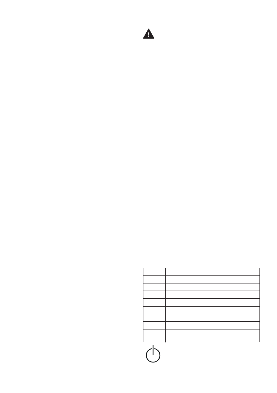
Bluetooth
®
The Bluetooth
®
word mark and logos are regis‐
tered trademarks owned by Bluetooth SIG, Inc.
These word mark/logos are used by STIHL
under license.
If the battery is equipped with a Bluetooth
®
inter‐
face, local operating restrictions (in aircraft or
hospitals, for example) must be observed.
Other Trademarks
Apple and the Apple logo are trademarks of
Apple Inc., registered in the U.S. and other coun‐
tries.
App Store is a service mark of Apple Inc.
Google Play and the Google Play logo are trade‐
marks of Google Inc.
26.3 Chain Sprockets
The following chain sprockets are available for
this model pole pruner:
–
7-tooth for 3/8" PICCO pitch
26.4 Minimum Groove Depth of
Guide Bars
The minimum groove depth of a guide bar
depends on the pitch of the guide bar.
–
Minimum groove depth for 3/8" PICCO pitch
guide bars: 0.197 in. (5 mm)
26.5 Depth Gauge Setting
The depth gauge setting of a saw chain depends
on the pitch of the chain.
–
Depth gauge setting for 3/8" PICCO pitch
chains: 0.026 in. (0.65 mm)
26.6 Ambient Temperature Limits
WARNING
■ Extreme temperatures can damage the battery
and may also cause it to generate heat, rup‐
ture, leak, ignite or explode, resulting in severe
or fatal personal injury or property damage.
Never charge, use or store the battery outside
the ambient temperature limits specified
below.
–
Do not charge the battery below - 4 °F (-
20 °C) or above 122 °F (50 °C).
–
Do not use the pole pruner or battery below
‑ 4 °F (- 20 °C) or above 122 °F (50 °C).
–
Do not store the pole pruner or battery
below - 4 °F (- 20 °C) or above 158 °F
(70 °C).
26.7 Ambient Temperature Recom‐
mendations
For optimum performance, observe the following
ambient temperature ranges for the pole pruner
and battery:
–
Charging: 41 °F to 104 °F (5 °C to 40 °C)
–
Use: 14 °F to 104 °F (- 10 °C to 40 °C)
–
Storage: - 4 °F to 122 °F (- 20 °C to 50 °C)
Charging, using or storing the battery outside the
recommended ambient temperature ranges may
reduce performance.
If the battery became damp or wet during opera‐
tion, allow it to dry at least 48 hours at tempera‐
tures between 59 °F (15 °C) and 122 °F (50 °C)
and relative humidity below 70 % before charg‐
ing or storing. Higher humidity can extend the
drying time.
26.8 Symbols on the Pole Pruner
Symbol Explanation
V Volt
Hz Hertz
A Ampere
Ah Ampere hour
W Watt
Wh Watt hour
AC Alternating current
IPX4 Protection against spraying or splash‐
ing water from all directions.
Power symbol on the retaining latch.
English 26 Specifications
38 0458-698-8621-B

Engage the clamping nut
Disengage the clamping nut
Chain oil tank
Direction of saw chain rotation
Turn clockwise to tension the saw
chain
STIHL products must not be disposed
of in the household trash, but only in
accordance with local, state and fed‐
eral laws and regulations and as pro‐
vided in this manual, 30.
Direct current
Number of cells and stored energy
according to cell manufacturer's speci‐
fication. Usable energy will be less.
The RBRC seal indicates that STIHL
has prepaid for battery recycling.
Read the manual
The battery is equipped with Blue‐
tooth
®
and can be connected with
the STIHL connected App.
26.9 Engineering Improvements
STIHL's philosophy is to continually improve all
of its products. As a result, engineering changes
and improvements are made from time to time.
Therefore, some changes, modifications and
improvements may not be covered in this man‐
ual. If the operating characteristics or the appear‐
ance of your machine differs from those descri‐
bed in this manual, please contact your STIHL
dealer or the STIHL distributor in your area for
assistance.
26.10 FCC 15 Compliance Statement
This device complies with part 15 of the FCC
Rules.
Operation is subject to the following two condi‐
tions:
1)
This device may not cause harmful interfer‐
ence, and
2)
this device must accept any interference
received, including interference that may
cause undesired operation.
Note: This equipment has been tested and found
to comply with the limits for a Class B digital
device, pursuant to part 15 of the FCC Rules.
These limits are designed to provide reasonable
protection against harmful interference in a resi‐
dential installation. This equipment generates,
uses and can radiate radio frequency energy
and, if not installed and used in accordance with
the instructions, may cause harmful interference
to radio communications. However, there is no
guarantee that interference will not occur in a
particular installation.
If this equipment does cause harmful interfer‐
ence to radio or television reception, which can
be determined by turning the equipment off and
on, the user is encouraged to try to correct the
interference by one or more of the following
measures:
–
reorient or relocate the receiving antenna,
–
increase the separation between the equip‐
ment and receiver,
–
connect the equipment to an outlet on a circuit
different from that to which the receiver is con‐
nected,
–
consult an authorized STIHL servicing dealer
or an experienced radio/TV technician for
help.
Do not change or modify this product in any way
unless specifically allowed in this manual, since
this could void your authority to operate it.
26 Specifications English
0458-698-8621-B 39
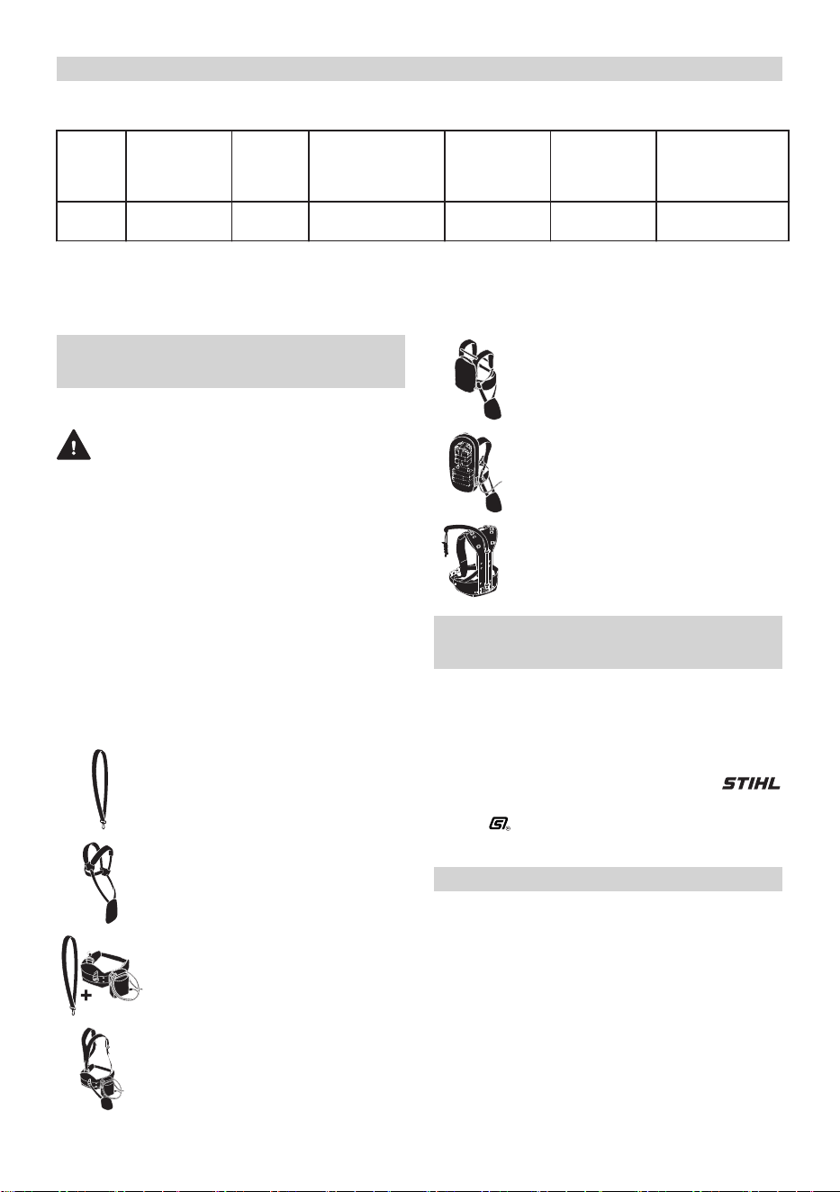
27 Combinations of Guide Bars and Saw Chains
27.1 STIHL HTA 135
Pitch Drive link
gauge/
Groove width
Length Guide bar Number of
teeth of
sprocket
nose
Drive link
count
Saw chain
3/8" P
0.043 in.
(1.1 mm)
10 in.
(25 cm)
Rollomatic E /
Light 04
7 39
61 PMM3 (Type
3610)
The listed guide bars are green-labeled reduced kickback STIHL guide bars. The listed chains are
green-labeled low kickback STIHL chains
Since new bar/chain combinations may be developed after publication of this manual, ask your author‐
ized STIHL servicing dealer for the latest STIHL recommendations.
28 Approved Harness Combi‐
nations
28.1 Harness Combinations
WARNING
■ The operator must be able to remove the har‐
ness quickly in the event of an emergency. To
reduce the risk of injury in an emergency:
–
Practice removing and putting down the
power tool as you would in an emergency.
To avoid damage, do not throw the power
tool to the ground when practicing.
–
Use only one of the allowed harness
options. Do not combine different harnesses
or other harness combinations when using
your power tool.
The following harnesses are available for your
pole pruner:
Shoulder Strap
Full Harness
STIHL Battery Belt with STIHL AP
Battery Bag with Connecting Cord
in combination with the Shoulder
Strap
STIHL Battery Belt with STIHL AP
Battery Bag with Connecting Cord
in combination with the Shoulder
Harness and Hip Pad
STIHL AR Backpack Battery in
combination with Hip Pad
STIHL Battery Backpack in combi‐
nation with Hip Pad
RTS Harness
29 Replacement Parts and
Equipment
29.1 Genuine STIHL Replacement
Parts
STIHL recommends the use of genuine STIHL
replacement parts. Genuine STIHL parts can be
identified by the STIHL part number, the
logo and, in some cases, by the STIHL parts
symbol . The symbol may appear alone on
small parts.
30 Disposal
30.1 Disposal of the Power Tool
STIHL products must not be thrown in household
trash or disposed of except as outlined in this
manual.
► Take the power tool, accessories and packag‐
ing to an approved disposal site for environ‐
mentally friendly recycling.
►
Contact your authorized STIHL
servicing
dealer for the latest information on disposal
and recycling.
English 27 Combinations of Guide Bars and Saw Chains
40 0458-698-8621-B

30.2 Battery Recycling
WARNING
■ Handle discharged/depleted batteries care‐
fully. Even if believed to be discharged, lithium
ion batteries may never totally discharge and
still may deliver a dangerous short circuit cur‐
rent. If damaged or exposed to extreme tem‐
peratures, they may leak, generate heat, catch
fire or explode.
► Observe all federal, state and local disposal
rules and regulations.
►
Contact your authorized STIHL servicing
dealer for the latest information on waste dis‐
posal.
► Recycle depleted batteries promptly.
► Keep batteries away from children. Do not dis‐
assemble and do not dispose of in fire.
STIHL is committed to the develop‐
ment of products that are environmen‐
tally responsible. This commitment
does not stop when the product
leaves the authorized STIHL servicing
dealer. STIHL has partnered with the
RBRC (Rechargeable Battery Recy‐
cling Corporation) to promote the col‐
lection and recycling of spent STIHL
lithium ion batteries in the United
States and Canada.
The RBRC seal indicates that STIHL has prepaid
for battery recycling. RBRC has a toll free phone
number (1-800-822-8837) that connects you to
information on battery recycling locations and
information on battery disposal bans or restric‐
tions in your area. You can also return your
spent battery to any authorized STIHL servicing
dealer for recycling free of charge.
31 Limited Warranty
31.1 STIHL Incorporated Limited
Warranty Policy
This product is sold subject to the STIHL Incor‐
porated Limited Warranty Policy, available at
www.stihlusa.com/warranty.html. It can also be
obtained from your authorized STIHL dealer or
by calling 1‑800‑GO‑STIHL (1‑800‑467‑8445).
32 Trademarks
32.1 Registered Trademarks
STIHL
®
FARM BOSS
®
iCademy
®
MAGNUM
®
STIHL Cutquik
®
MasterWrench Service
®
ROCK BOSS
®
MotoMix
®
KISS MY AXE
®
OILOMATIC
®
AutoCut
®
STIHL DUROMATIC
®
YARD BOSS
®
STIHL Quickstop
®
STIHL ROLLO‐
MATIC
®
STIHL WOOD BOSS
®
WOOD BOSS
®
TIMBERSPORTS
®
DIRT BOSS
®
iMOW
®
The color combination
orange-grey (U. S. Regis‐
trations 2,821,860;
3,010,057; 3,010,058;
3,400,477; and
3,400,476)
32.2 Common Law Trademarks
4-MIX™ STIHL Injection™
BioPlus™ STIHL PowerSweep™
Easy2Start™ Team STIHL™
EasySpool™ HEXA™
ElastoStart™ IntelliCarb™
Ematic™ Master Control Lever™
STIHL Precision Ser‐
ies™
STIHL OUTFITTERS™
FixCut™ STIHL PICCO™
Micro™ TrimCut™
Pro Mark™ STIHL M-Tronic™
TapAction™ On A Single Charge™
Quiet Line™ STIHL PolyCut™
STIHL Moto4™ STIHL RAPID™
STIHL SuperCut™
This listing of trademarks is subject to change.
Any unauthorized use of these trademarks with‐
out the express written consent of
ANDREAS STIHL AG & Co. KG, Waiblingen is
strictly prohibited.
33 Addresses
33.1 STIHL Incorporated
STIHL Incorporated
536 Viking Drive
P.O. Box 2015
Virginia Beach, VA
23452-2015
31 Limited Warranty español / EE.UU
0458-698-8621-B 41
© ANDREAS STIHL AG & Co. KG 2025
0458-698-8621-B. VA2.B25.
Impreso en papel libre de cloro.
El papel es reciclable.
Manual de instrucciones original
0000009293_011_EA
Contenido
1 Introducción.............................................. 42
2 Acerca de este manual de instrucciones.. 42
3 Componentes importantes........................43
4 Símbolos de seguridad en los productos..44
5 Advertencias generales de seguridad para
herramientas motorizadas........................ 45
6 INSTRUCCIONES IMPORTANTES DE
SEGURIDAD.............................................47
7 Contragolpe y otras fuerzas reactivas...... 56
8 Seguridad de la batería.............................57
9 Mantenimiento, reparación y almacena‐
miento....................................................... 59
10 Antes de empezar a trabajar.....................60
11 Carga de la batería................................... 60
12 Diagnóstico por LED y señales acústicas.62
13 Interfaz Bluetooth® de Radio....................63
14 Batería de mochila STIHL AR...................63
15 Montaje del podador de varilla..................65
16 Colocación y extracción de la batería....... 69
17 Encendido y apagado del podador de varilla
.................................................................. 70
18 Revisión del podador de varilla.................71
19 Durante el funcionamiento........................ 72
20 Después de completar el trabajo.............. 74
21 Transporte del podador de varilla y de la
batería.......................................................74
22 Almacenamiento del podador de varilla y de
la batería................................................... 75
23 Limpieza....................................................76
24 Inspección y mantenimiento..................... 77
25 Guía de solución de problemas................ 81
26 Especificaciones....................................... 82
27 Combinaciones de espadas y cadenas de
aserrado....................................................85
28 Combinaciones de arnés aprobadas........ 85
29 Piezas y equipos de repuesto...................86
30 Eliminación................................................86
31 Garantía limitada.......................................86
32 Marcas comerciales.................................. 86
33 Direcciones............................................... 87
1 Introducción
Gracias por su compra. La información que con‐
tiene este manual le ayudará a obtener el
máximo rendimiento y la mayor satisfacción de
su podador de varilla de STIHL, y a reducir el
riesgo de lesiones que supone su uso, si respeta
esta información.
CONSERVE ESTE MANUAL
Dado que el podador de varilla es
una herramienta motorizada para
cortar madera de gran velocidad y
de alcance muy largo, es necesa‐
rio tomar medidas de seguridad
especiales para reducir el riesgo
de lesiones.
Lea este manual de instrucciones
detenidamente antes de usar el
equipo por primera vez, y periódi‐
camente de allí en adelante. Res‐
pete todas las medidas de seguri‐
dad. Un uso descuidado o inade‐
cuado del podador de pértiga
puede causar lesiones graves o
mortales.
Respete todas las regulaciones, normas y regla‐
mentaciones de seguridad federales, estatales y
locales aplicables.
No preste ni alquile su podador de varilla sin
entregar también este manual de instrucciones.
Asegúrese de que solo usan el podador de vari‐
lla personas debidamente capacitadas que com‐
prendan íntegramente la información de este
manual.
Si necesita más información, o si no comprende
alguna de las instrucciones incluidas en este
manual, visite www.stihlusa.com o póngase en
contacto con su concesionario de servicio autori‐
zado de STIHL.
2 Acerca de este manual de
instrucciones
2.1 Palabras identificadoras
Este manual contiene información sobre seguri‐
dad a la que usted debe prestar especial aten‐
ción. Dicha información se indica con los
siguientes símbolos y palabras identificadoras:
PELIGRO
■ Identifica una situación de peligro que, de no
evitarse, causará lesiones graves o mortales.
ADVERTENCIA
■ Identifica una situación de peligro que, de no
evitarse, puede causar lesiones graves o mor‐
tales.
INDICACIÓN
■ Indica el riesgo de daños a la propiedad, inclu‐
yendo a la máquina o sus componentes.
2.2 Símbolos en el texto
El siguiente símbolo tiene como finalidad ayu‐
darlo a utilizar este manual.
español / EE.UU 1 Introducción
42 0458-698-8621-B
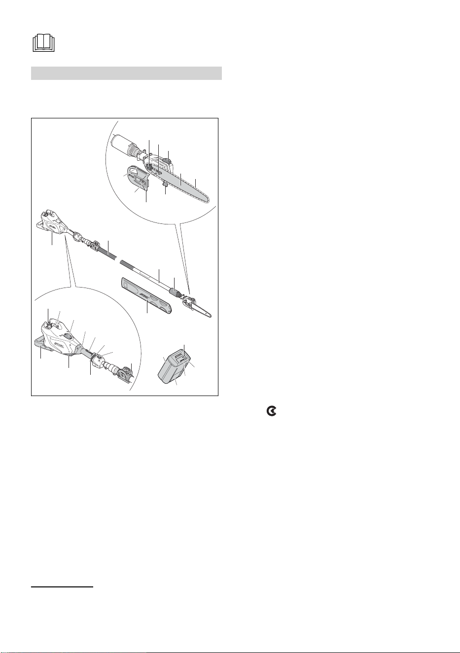
Hace referencia a un capítulo o subcapí‐
tulo designado en este manual de ins‐
trucciones.
3 Componentes importantes
3.1 Podadora de pértiga y batería
STIHL HTA 135
0000097168_005
17
#
16
15
14
13
28
27
26
#
1
18
25
19
21
20
22
23
24
4
5
6
2
3
10
9
7
8
11
12
1 Mango delantero
Mango para la mano delantera del operador.
2 Tubo de mando
Eje del podador de varilla.
3 Tuerca de sujeción
Para ajustar la longitud del tubo de mando.
4 Piñón de la cadena
Impulsa la cadena de aserrado.
5 Tensor lateral de la cadena
Permite ajustar con precisión la tensión de la
cadena de sierra.
6 Tapa de llenado de aceite
Para cerrar el depósito de aceite.
7 Barra guía
Sirve de soporte y de guía de la cadena de
sierra.
8 Cadena de aserrado
Herramienta de corte dentada formada por
cortadores, amarras y eslabones impulsores.
9 Gancho
Ayuda a mantener la podadora de pértiga fija
contra la rama durante el corte.
10 Cubierta del piñón de la cadena
Cubre el piñón de la cadena.
11 Tuerca
Aprieta la cubierta del piñón de la cadena.
12 Mira de desrame
Ayuda al operador a posicionar la barra y la
cadena para el corte.
13 Vaina de la cadena
Cubre la espada y la cadena de aserrado
para reducir el riesgo de lesiones causadas
por un contacto accidental durante el trans‐
porte o el almacenamiento.
14 Batería
Suministra energía eléctrica al motor.
15 LED de la batería
Indican el estado de carga de la batería y
muestran mensajes de error sobre posibles
fallos de funcionamiento de la batería o de la
herramienta motorizada.
16 Pulsador
Activa los LED de la batería. Activa y desac‐
tiva la interfaz de Bluetooth® (si aplica).
17
LED de "BLUETOOTH
®
" (solo para baterías
con
)
Indica si la interfaz de Bluetooth® está acti‐
vada o desactivada.
18 Palancas de bloqueo
Fijan la batería en su compartimiento.
19 Compartimiento de la batería
Espacio en donde se coloca la batería.
20
Cubierta de hueco de montaje
4
Cubre la zona de montaje de un Conector
inteligente 2 A.
21 Mango de control
Mango para la mano trasera del operador.
4
Retire la tapa del hueco de montaje sólo para instalar un Smart Connector 2 A. Guárdelo de forma
segura para su posterior reinstalación. Utilice siempre la herramienta eléctrica con la cubierta del
hueco de montaje colocada o con el Smart Connector 2 A montado.
3 Componentes importantes español / EE.UU
0458-698-8621-B 43
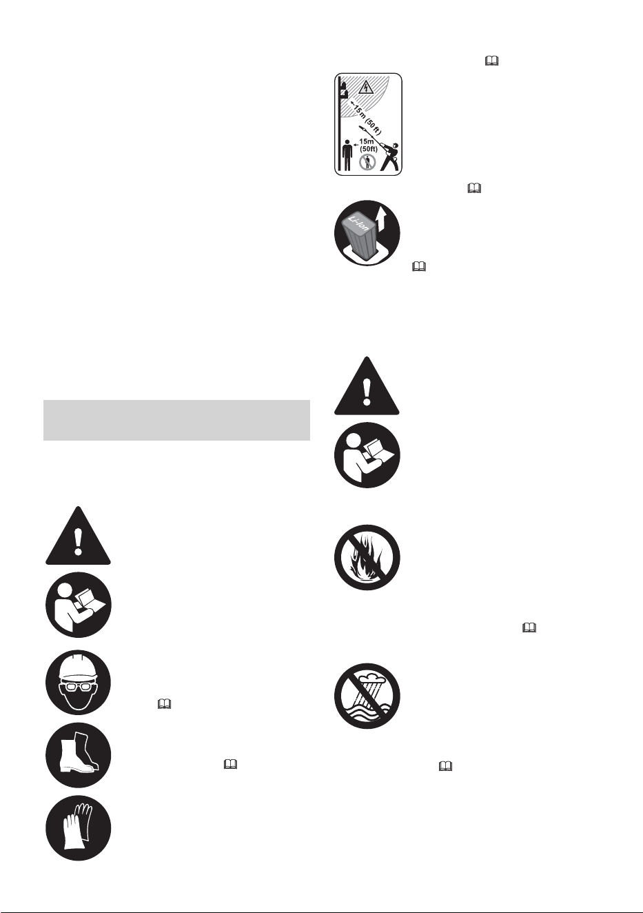
22 Bloqueo del disparador
Se debe presionar para permitir la activación
del gatillo.
23 Pestillo de retención
Para encender el podador de varilla.
24 LED
Indican el nivel de potencia de la máquina.
25 Pinza para arnés
Para enganchar un arnés al podador de vari‐
lla.
26 Gatillo
Cuando se presiona, activa la cadena de ase‐
rrado.
27 Filtro de aire
Filtra el aire que se aspira y entra en el
motor.
28 Apoyo a las máquinas
Para apoyar el podador de varilla en el suelo.
# Placa de características
Contiene los datos eléctricos y el número de
serie del producto.
4 Símbolos de seguridad en
los productos
4.1 Podador de varilla
En el podador de varilla se pueden ver los
siguientes símbolos de seguridad:
Para reducir el riesgo de lesiones,
respete las medidas de seguridad
especificadas.
Lea y respete todas las medidas
de seguridad que se dan en el
manual de instrucciones. Un uso
inadecuado puede provocar lesio‐
nes graves o mortales, o daños
materiales.
Para reducir el riesgo de lesiones
oculares o en la cabeza, use
siempre gafas protectoras ade‐
cuadas y un casco protector apro‐
bado, 6.3.
Lleve botas resistentes con suela
antideslizante. Le recomendamos
que elija botas de seguridad con
puntera de acero, 6.3.
Use siempre guantes de trabajo
gruesos y no resbaladizos (por
ejemplo, de cuero o de otro mate‐
rial resistente al desgaste), para
manejar la máquina o la cadena
de aserrado, 6.3.
Para reducir el riesgo de lesio‐
nes, asegúrese de que no hay
nadie a una distancia de al
menos 50 pies (15 m), y de que
hay al menos 50 pies (15 m)
entre el podador de varilla
(incluida cualquier rama con la
que esté en contacto) y cualquier
línea que conduzca corriente
eléctrica,
6.5.4.
Para reducir el riesgo de lesiones
y de daños materiales provocados
por una activación accidental,
retire la batería siempre que el
podador de varilla no esté en uso,
6.4.
4.2 Batería
Los siguientes símbolos de seguridad se
encuentran en la batería de mochila serie AR y
en la batería serie AP:
Para reducir el riesgo de lesiones,
respete las medidas de seguridad
especificadas.
Lea y respete todas las precaucio‐
nes de seguridad dadas en el
manual de instrucciones de la
batería y en el manual de la herra‐
mienta STIHL que utiliza esta
batería. Un uso inadecuado puede
provocar lesiones graves o morta‐
les, así como daños materiales.
Para reducir el riesgo de lesiones
y de daños materiales provoca‐
dos por incendios, explosiones o
quemaduras, incluidas quemadu‐
ras químicas, no desarme,
aplaste, deje caer, dañe ni
caliente a más de 212 °F
(100 °C). Nunca la exponga al
fuego ni la incinere,
8.
Baterías de mochila AR 1000, 2000, 3000
Para reducir el riesgo de lesiones
personales o daños a la propie‐
dad causados por un cortocir‐
cuito, un incendio o una explo‐
sión, mantenga la unidad seca.
Protéjala contra la lluvia, el agua y
las condiciones húmedas. Nunca
la sumerja en agua u otros líqui‐
dos,
8.
español / EE.UU 4 Símbolos de seguridad en los productos
44 0458-698-8621-B

Baterías de mochila AR L
Para reducir el riesgo de lesiones
personales o daños a la propie‐
dad causados por un cortocir‐
cuito, un incendio o una explo‐
sión, mantenga la unidad seca.
Nunca la sumerja en agua u otros
líquidos, 8.
Baterías serie AP
Para reducir el riesgo de lesiones
personales o daños a la propie‐
dad causados por un cortocir‐
cuito, un incendio o una explo‐
sión, mantenga la unidad seca.
Nunca la sumerja en agua u otros
líquidos, 8.
Las baterías se venden por separado.
5 Advertencias generales de
seguridad para herramien‐
tas motorizadas
5.1 Introducción
Este capítulo contiene las advertencias e instruc‐
ciones de seguridad generales prescritas para
herramientas motorizadas eléctricas manuales.
En los siguientes capítulos de este manual, se
proporcionan otras advertencias e instrucciones
importantes.
ADVERTENCIA
■
Lea todas las advertencias de seguridad y
todas las instrucciones. Si no se siguen todas
las advertencias e instrucciones, se podrían
producir descargas eléctricas, incendios o
lesiones graves.
■
Conserve todas las advertencias e instruccio‐
nes para referencia en el futuro.
El término “herramienta eléctrica” que aparece
en las advertencias hace referencia a una herra‐
mienta alimentada por cordón eléctrico o a bate‐
ría (inalámbrica).
5.2 Seguridad en la zona de tra‐
bajo
a
)
Mantenga la zona de trabajo limpia y bien
iluminada. El desorden y la oscuridad favore‐
cen los accidentes.
b)
No utilice las herramientas motorizadas en
entornos potencialmente explosivos, tales
como aquellos en los que hay líquidos,
gases o polvos inflamables. Las herramien‐
tas motorizadas producen chispas que
podrían encender el polvo o los vapores.
c)
Asegúrese de que niños y terceras personas
se mantienen alejados de la herramienta
motorizada mientras la está usando. Cual‐
quier distracción podría hacerle perder el
control sobre la herramienta.
5.3 Seguridad eléctrica
a)
El enchufe de la herramienta motorizada
debe corresponder con el tomacorriente.
Nunca modifique el enchufe en modo
alguno. No utilice enchufes adaptadores con
herramientas motorizadas que tengan clavija
de puesta a tierra. El uso de enchufes no
modificados y de los tomacorrientes adecua‐
dos reduce el riesgo de descargas eléctri‐
cas.
b)
Evite que su cuerpo entre en contacto con
superficies puestas a tierra tales como tube‐
rías, radiadores, estufas y refrigeradores. Si
su cuerpo está conectado con tierra, existe
un mayor riesgo de que sufra descargas
eléctricas.
c)
No exponga las herramientas motorizadas a
la lluvia ni a la humedad. Si entra agua en la
herramienta motorizada, aumenta el riesgo
de que se produzcan descargas eléctricas.
d)
No maltrate el cordón eléctrico. Nunca tire
del cordón eléctrico para transportar, arras‐
trar o desenchufar la herramienta motori‐
zada. Mantenga el cordón protegido del
calor y alejado de aceites, bordes afilados y
piezas móviles. Si el cordón está dañado o
retorcido, aumenta el riesgo de que se pro‐
duzcan descargas eléctricas.
e)
Cuando use una herramienta motorizada a
la intemperie, utilice un cordón de extensión
adecuado para el uso en exteriores. Con un
cordón apto para el uso en exteriores se
reduce el riesgo de descargas eléctricas.
f)
Si resulta ineludible el uso de una herra‐
mienta motorizada en un lugar húmedo, uti‐
lice un suministro de energía eléctrica con
dispositivo de corriente residual (RCD) o con
protección contra pérdidas a tierra (GFCI). El
uso de un RCD o GFCI reduce el riesgo de
descargas eléctricas.
5.4 Seguridad personal
a
)
Manténgase alerta, preste atención a lo que
hace y aplique el sentido común cuando use
una herramienta motorizada. No utilice una
5 Advertencias generales de seguridad para herramientas motorizadas español / EE.UU
0458-698-8621-B 45

herramienta motorizada si se nota cansado o
si está bajo la influencia de drogas, alcohol o
medicamentos. Un descuido breve durante
el uso de una herramienta motorizada puede
causar lesiones personales graves.
b)
Utilice equipos de protección personal. Pro‐
téjase los ojos siempre. El uso de equipos
protectores como mascarillas, zapatos de
seguridad antideslizantes, casco y protecto‐
res de los oídos para lograr las condiciones
de trabajo apropiadas reduce el riesgo de
sufrir lesiones personales.
c)
Evite los arranques accidentales. Asegúrese
de que el interruptor está en la posición de
apagado antes de conectar la máquina a la
fuente de energía o a la batería, antes de
levantarla y antes de cargarla. Cargar una
herramientas motorizadas con un dedo colo‐
cado sobre el interruptor de encendido o
conectar la alimentación de herramientas
que tienen el interruptor en la posición de
encendido favorece los accidentes.
d)
Retire todas las llaves o herramientas de
ajuste antes de encender la herramienta
motorizada. Si se deja una herramienta o
una llave colocada en un componente girato‐
rio de la herramienta motorizada, se pueden
producir lesiones personales.
e)
No extienda los brazos más de lo necesario.
Mantenga el equilibrio y los pies bien apoya‐
dos en todo momento. Así, podrá controlar
mejor la herramienta motorizada si surge
cualquier imprevisto.
f)
Use vestimenta adecuada. No utilice ropa
suelta ni joyas. Mantenga su cabello y su
ropa alejados de las piezas móviles. La ropa
suelta, las joyas o el cabello largo pueden
quedar atrapados en los componentes en
movimiento.
g)
Si cuenta con dispositivos para la conexión
de equipos extractores y recogedores de
polvo, asegúrese de que estos están conec‐
tados y de que se usan debidamente. El uso
de un equipo recogedor de polvo puede
reducir los peligros relacionados con el
polvo.
h)
No permita que la familiaridad adquirida con
el uso frecuente de las herramientas lo lleve
a actuar con un exceso de confianza y a no
tener en cuenta los principios de seguridad
de la herramienta. Una acción descuidada
puede causar lesiones graves en una frac‐
ción de un segundo.
5.5 Uso y cuidado de la herra‐
mienta motorizada
a)
No fuerce la herramienta motorizada. Utilice
la herramienta motorizada adecuada para el
trabajo que va a realizar. Si usa la herra‐
mienta motorizada correcta, llevará a cabo la
tarea mejor y con mayor seguridad, y al
ritmo para el cual fue diseñada.
b)
No utilice la herramienta motorizada si no se
puede encender y apagar con el interruptor.
Toda herramienta motorizada que no pueda
controlarse con su interruptor es peligrosa y
debe ser reparada.
c)
Desconecte el enchufe de la fuente de ali‐
mentación o retire el paquete de baterías (si
es desmontable), de la herramienta motori‐
zada antes de hacer ajustes, cambiar acce‐
sorios o almacenar la herramienta. Estas
medidas preventivas de seguridad reducen
el riesgo de arrancar la herramienta motori‐
zada por accidente.
d)
Guarde las herramientas motorizadas fuera
del alcance de los niños, y no permita que
utilicen las herramientas personas que no
estén familiarizadas con ellas o con estas
instrucciones. En manos de personas no
capacitadas para usarlas, las herramientas
motorizadas son peligrosas.
e)
Mantenga debidamente las herramientas
motorizadas y sus accesorios. Compruebe si
los componentes móviles están mal alinea‐
dos o agarrotados, si hay roturas en alguna
pieza y otros aspectos que pudieran afectar
al funcionamiento de la herramienta eléc‐
trica. Si hay daños, envíe la herramienta
eléctrica a reparación antes de usarla.
Muchos accidentes se deben a un manteni‐
miento deficiente de las herramientas motori‐
zadas.
f)
Mantenga las herramientas de corte afiladas
y limpias. Si se han mantenido correcta‐
mente y están afiladas, las herramientas de
corte son menos propensas a atascarse y
más fáciles de controlar.
g)
Utilice la herramienta motorizada, los acce‐
sorios, las brocas, etc. tal como se indica en
estas instrucciones, teniendo en cuenta las
condiciones de trabajo y el tipo de tarea que
va a realizar. El uso de una herramienta
motorizada para trabajos diferentes a aque‐
llos para los que fue diseñada puede produ‐
cir situaciones peligrosas.
español / EE.UU 5 Advertencias generales de seguridad para herramientas motorizadas
46 0458-698-8621-B

h)
Mantenga los mangos y las superficies de
agarre secos, limpios y sin aceite ni grasa.
Las superficies de agarre y los mangos res‐
baladizos dificultan la manipulación y el con‐
trol seguros de la herramienta en situaciones
inesperadas.
5.6 Uso y cuidado de la herra‐
mienta con batería
a)
Recárguela únicamente con el cargador
especificado por el fabricante. Un cargador
que es adecuado para un tipo de baterías
puede crear un riesgo de incendio si se uti‐
liza con baterías de un tipo diferente.
b)
Utilice las herramientas motorizadas única‐
mente con las baterías especificadas para
ellas. El uso de otras baterías puede crear
riesgos de lesiones o incendio.
c)
Cuando no utilice las baterías, manténgalas
alejadas de objetos metálicos tales como
presillas para papel, monedas, llaves, cla‐
vos, tornillos u otros objetos metálicos
pequeños que pudieran establecer una
conexión entre los distintos terminales. Un
cortocircuito entre los terminales de batería
puede causar quemaduras o un incendio.
d)
En condiciones de maltrato, podría salir
líquido de la batería; evite el contacto con el
mismo. Si, a pesar de todo, el contacto se
produce, lave la zona afectada con agua. Si
el líquido entra en contacto con los ojos,
busque además atención médica. El líquido
que sale de la batería puede causar irritacio‐
nes y quemaduras.
e)
No utilice una batería ni una herramienta a
batería que presente daños o haya sido
modificada. Las baterías dañadas o modifi‐
cadas pueden tener un comportamiento
impredecible y que puede provocar incen‐
dios, explosiones y lesiones.
f)
No exponga nunca un paquete o herra‐
mienta con batería al fuego ni a temperatu‐
ras excesivas. La exposición al fuego o a
temperaturas superiores a los 130 °C/
265 °F puede causar una explosión.
g)
Respete todas las instrucciones relativas a la
carga y no cargue el paquete ni la herra‐
mienta con batería a temperaturas fuera del
intervalo que se especifica en las instruccio‐
nes. Una carga incorrecta o realizada a tem‐
peraturas fuera del intervalo especificado
puede dañar la batería y aumentar el riesgo
de incendios.
5.7 Mantenimiento
a)
El mantenimiento de su herramienta motori‐
zada deberá realizarlo siempre un técnico
calificado, utilizando piezas de repuesto
genuinas. Solo así queda garantizado que
se mantendrá intacta la seguridad de la
herramienta motorizada.
b)
Nunca intente reparar baterías dañadas. Del
mantenimiento de las baterías deben encar‐
garse únicamente el fabricante o un provee‐
dor de servicio autorizado.
6 INSTRUCCIONES IMPOR‐
TANTES DE SEGURIDAD
6.1 Uso previsto
ADVERTENCIA
■ Este podador de varilla está diseñado única‐
mente para recortar ramas. No está diseñado
para ser utilizado como palanca o pala en las
ramas, raíces u otros objetos. El uso del poda‐
dor de varilla para trabajos para los que no ha
sido diseñado puede causar lesiones graves o
mortales.
–
Corte únicamente madera. Por ejemplo, no
use el podador de varilla para cortar metal,
plástico o mampostería.
■
Antes de comenzar cualquier trabajo de des‐
ramado, asegúrese de que todos los cortes
necesarios se pueden completar usando la
carga que queda en la batería STIHL de la
serie AP o AR. Si tiene dudas:
–
Tenga varias baterías cargadas listas para
usar.
–
Elija un podador de varilla más potente.
–
Elija una batería más potente. O bien:
–
Consulte a un profesional reputado especia‐
lizado en árboles.
■ Lea y respete las instrucciones de manejo y
uso que se dan en este manual para conocer
las aplicaciones aprobadas y las técnicas de
trabajo recomendadas.
■
Un uso indebido podría provocar lesiones o
daños materiales, incluidos daños en el poda‐
dor de varilla.
–
Use el podador de varilla y la batería única‐
mente como se describe en este manual.
–
Nunca intente modificar ni anular los contro‐
les ni los dispositivos de seguridad del
podador de varilla en modo alguno.
–
Nunca utilice un podador de varilla que se
haya modificado o alterado, apartándose de
su diseño original.
6 INSTRUCCIONES IMPORTANTES DE SEGURIDAD español / EE.UU
0458-698-8621-B 47

–
Asegúrese de leer y respetar las adverten‐
cias y las instrucciones de su batería y de
su cargador antes de iniciar la carga o de
empezar a trabajar.
■
Esta herramienta motorizada puede alimen‐
tarse con una batería de la serie STIHL AP.
Alternatively, it may be powered by a
STIHL AR series backpack battery in combi‐
nation with an ADA 100.
La batería STIHL AP con utiliza tecnología
Bluetooth
®
para intercambiar información con los
dispositivos móviles que ejecuten la aplicación
STIHL connected.
Las baterías, los cargadores y otros accesorios
se venden por separado.
6.2 Operador
ADVERTENCIA
■ Trabajar con la podadora de pértiga puede ser
agotador. El operador debe encontrarse en
buenas condiciones, tanto físicas como men‐
tales. Para reducir el riesgo de lesiones:
–
Consulte a su médico antes de usar la
podadora de pértiga si tiene cualquier afec‐
ción de la salud que pueda verse agravada
por un trabajo agotador.
–
No utilice el podador de varilla si se encuen‐
tra bajo la influencia de cualquier sustancia
(drogas, alcohol, medicamentos, etc.) que
pudiera afectar la visión, el equilibrio, la
destreza o el juicio.
–
Permanezca alerta. No use el podador de
varilla si está cansado. Si se cansa, haga
una pausa.
–
No permita que los niños usen el podador
de varilla.
–
No permita la proximidad de otras perso‐
nas, especialmente niños, ni de animales,
en la zona en que esté utilizando el podador
de varilla.
■
El uso prolongado de un podador de varilla (o
de otras herramientas motorizadas) que
expone al operador a vibraciones puede cau‐
sar la enfermedad de dedos blancos (fenó‐
meno de Raynaud) o el síndrome del túnel
carpiano. Estas afecciones reducen la capaci‐
dad de la mano de sentir y regular la tempera‐
tura. Producen entumecimiento y sensación
de ardor, y pueden causar también daños en
los nervios y en la circulación, además de
necrosis tisular.
■ No se conocen todos los factores que contri‐
buyen a la enfermedad de los dedos blancos.
El clima frío, el consumo de tabaco y las
enfermedades o afecciones físicas que afec‐
tan a los vasos sanguíneos y a la circulación
de la sangre, además de los niveles altos de
vibración y los periodos largos de exposición a
vibraciones, figuran entre los factores que
contribuyen al desarrollo de la enfermedad de
los dedos blancos.
■ Para reducir el riesgo de desarrollar la enfer‐
medad de los dedos blancos y el síndrome de
túnel carpiano:
–
Use guantes cuando trabaje, y mantenga
las manos abrigadas.
–
Mantenga el podador de varilla en buen
estado de mantenimiento. Un podador de
varilla que no se ha mantenido correcta‐
mente o que tiene componentes sueltos
tiende a tener niveles de vibración más
altos.
–
Mantenga la cadena de aserrado afilada.
Una cadena roma aumentará el tiempo de
corte; atravesar madera con una cadena
roma aumentará las vibraciones que se
transmiten a las manos del operador.
–
Agarre los mangos firmemente en todo
momento, pero no los apriete con una
fuerza constante y excesiva. Tómese des‐
cansos frecuentes.
■
Estas precauciones no garantizan que no
usted no vaya a sufrir la enfermedad de los
dedos blancos o el síndrome de túnel car‐
piano.
–
Controle atentamente el estado de sus
manos y dedos si es un usuario regular de
este tipo de herramientas.
–
Acuda inmediatamente al médico si nota
alguno de los síntomas mencionados ante‐
riormente.
■
Según los conocimientos actuales de STIHL,
el motor eléctrico de este podador de varilla
no interfiere con los marcapasos.
–
Sin embargo, las personas que lleven mar‐
capasos u otro dispositivo médico implan‐
tado deben consultar a su médico y al fabri‐
cante del dispositivo antes de utilizar esta
podadora de pértiga.
6.3 Equipos de protección personal
ADVERTENCIA
■
Para reducir el riesgo de lesiones personales:
–
Siempre use ropa adecuada y vestimenta
protectora, incluidas gafas de seguridad
adecuadas.
■
Si el cabello, la ropa o los equipos de protec‐
ción entran en contacto con la cadena de ase‐
español / EE.UU 6 INSTRUCCIONES IMPORTANTES DE SEGURIDAD
48 0458-698-8621-B
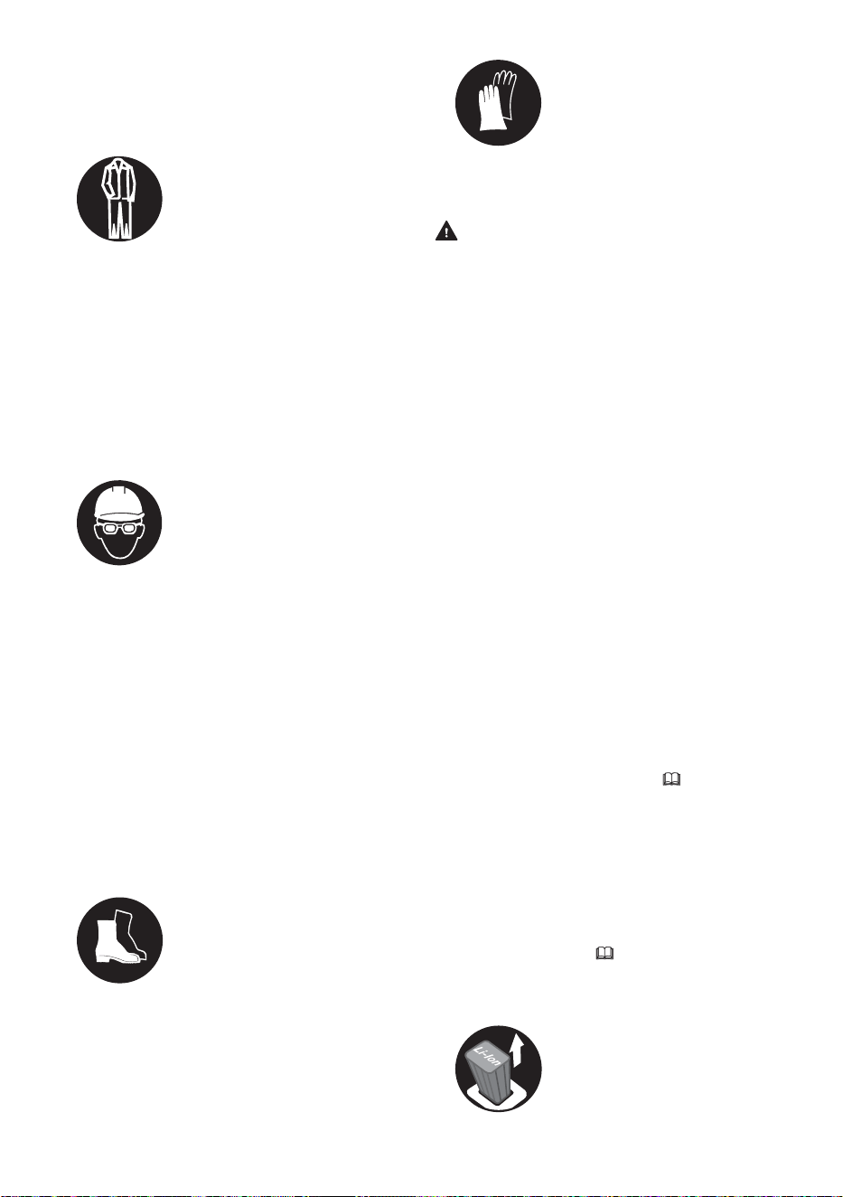
rrado en movimiento o se enredan en los com‐
ponentes del podador de varilla, podría per‐
derse el control sobre la máquina, lo que
podría producir lesiones cortantes graves.
Para reducir el riesgo de lesiones graves:
–
Use ropa resistente y ajus‐
tada que le permita
moverse con completa
libertad.
–
Use monos o pantalones
largos hechos de un mate‐
rial grueso para protegerse
las piernas. No lleve panta‐
lones cortos.
–
Evite el uso de chaquetas sueltas, bufan‐
das, corbatas, pantalones acampanados o
con vueltas, joyas o cualquier prenda que
pueda engancharse en ramas, en matorra‐
les o en la cadena en movimiento.
–
Sujétese el cabello por encima de los hom‐
bros antes de empezar a trabajar.
■ Para reducir el riesgo de sufrir lesiones ocula‐
res:
–
Siempre utilice gafas o
anteojos protectores bien
ajustados que tengan pro‐
tecciones adecuadas en la
parte superior y en los late‐
rales, que sean resistentes
a los impactos y que porten
la marca que indica que
cumplen la norma
ANSI Z87 "+".
–
Para reducir el riesgo de lesionarse la cara,
STIHL le recomienda que use también una
careta o un protector facial adecuado sobre
las gafas o los anteojos de seguridad.
■
Para reducir el riesgo de sufrir lesiones en la
cabeza por la caída de ramas o por el impacto
de otros objetos durante el trabajo:
–
Use un casco protector aprobado.
■ Es muy importante que mantenga los pies
bien apoyados en todo momento. Como
ayuda para mantener los pies apoyados de
forma segura y para reducir el riesgo de lesio‐
nes durante el trabajo:
–
Lleve botas resistentes con
suela antideslizante. Le
recomendamos que elija
botas de seguridad con
puntera de acero. Nunca
use sandalias, chanclas,
zapatos que dejen los
dedos al descubierto ni cal‐
zado similar.
■
Para mejorar el agarre y para proteger mejor
sus manos:
–
Siempre use guantes de
trabajo gruesos antidesli‐
zantes de cuero o de otro
material resistente al des‐
gaste para manipular el
podador de varilla o su
cadena.
6.4 Podadora de pértiga
ADVERTENCIA
■ Para reducir el riesgo de una descarga eléc‐
trica:
–
No sumerja el podador de varilla en agua ni
en otros fluidos.
–
Guarde el podador de varilla en interiores.
■ La cadena de sierra tiene muchos cortadores
afilados. El contacto con los cortadores puede
causar laceraciones graves, incluso cuando la
cadena no está en movimiento. Para reducir el
riesgo de que se produzcan este tipo de lesio‐
nes:
–
Mantenga las manos, los pies y cualquier
otra parte del cuerpo lejos de la cadena.
–
Use guantes de trabajo gruesos cuando
manipule el podador de varilla o la cadena
del mismo.
–
Nunca toque una cadena que esté en movi‐
miento con las manos ni con ninguna otra
parte del cuerpo.
–
Cubra la espada con una funda antes de
transportar o de guardar el podador de vari‐
lla, para reducir el riesgo lesiones causadas
por contacto accidental.
■
Las fuerzas reactivas, incluido el contragolpe,
pueden ser peligrosas.
–
Preste especial atención a la sección "Con‐
tragolpe y otras fuerzas reactivas" de este
manual de instrucciones, 7.
■
Este podador de varilla alimentado con batería
está diseñado únicamente para recortar
ramas. Su uso para otros fines puede aumen‐
tar el riesgo de lesiones y de daños materia‐
les.
–
Corte únicamente madera.
–
Lea y respete las instrucciones de manejo
de este manual para conocer las aplicacio‐
nes aprobadas, 19.4.
■
Para reducir el riesgo de que el operador o las
personas que se encuentran cerca sufran
lesiones:
–
Siempre suelte el gatillo y
retire la batería antes de
armar, transportar, ajustar,
inspeccionar, limpiar, repa‐
rar, mantener o guardar el
6 INSTRUCCIONES IMPORTANTES DE SEGURIDAD español / EE.UU
0458-698-8621-B 49

podador de varilla, y siem‐
pre que no esté en uso.
■ Aunque determinados accesorios no autoriza‐
dos podrían encajar en su podador de varilla
STIHL, su uso puede resultar extremada‐
mente peligroso. Le recomendamos que uti‐
lice únicamente accesorios suministrados por
STIHL o expresamente autorizados por STIHL
para el uso con este modelo específico.
–
Use solo accesorios suministrados o expre‐
samente aprobados por STIHL.
–
Nunca modifique este podador de varilla de
ninguna manera.
–
Nunca intente modificar ni anular los contro‐
les ni los dispositivos de seguridad del
podador de varilla en modo alguno.
–
Nunca utilice un podador de varilla que se
haya modificado o alterado, apartándose de
su diseño original.
■
Si el podador de varilla se cae o sufre un
impacto similar:
–
Asegúrese de que no se ha dañado, de que
está en buenas condiciones y de que fun‐
ciona correctamente antes de reanudar el
trabajo.
–
Compruebe que los controles y los dispositi‐
vos de seguridad funcionan correctamente,
18.1.
–
Revise los LED y compruebe si hay mensa‐
jes de error, 12.
–
Asegúrese de que la batería no se ha
dañado. Nunca use ni cargue una batería
que no funcione correctamente o que esté
dañada, agrietada, deformada o pierda
líquido.
–
Nunca trabaje con una podadora de pértiga
o con una batería que presenten averías o
funcionen mal. En caso de duda, encargue
a su concesionario de servicio STIHL autori‐
zado que revise la podadora de pértiga y la
batería.
■
Si la podadora de pértiga o la batería se daña,
no funciona correctamente, se ha dejado al
aire libre, se ha expuesto a lluvia o condicio‐
nes húmedas o se ha caído en agua u otro
líquido, es posible que sus componentes y los
dispositivos de seguridad ya no funcionen.
Para reducir el riesgo de lesiones y de daños
materiales:
–
Lleve el podador de varilla y la batería a su
concesionario de servicio de STIHL autori‐
zado para que los revisen antes de conti‐
nuar utilizándolos.
■
Las piezas de repuesto auténticas de STIHL
están diseñadas específicamente para su
podador de varilla, y satisfacen las necesida‐
des de rendimiento y seguridad correspon‐
dientes. El uso de piezas no autorizadas o no
aprobadas por STIHL puede provocar lesio‐
nes graves o mortales, así como daños mate‐
riales.
–
STIHL recomienda utilizar únicamente
repuestos de STIHL idénticos a las piezas
originales.
6.5 Uso del podador de varilla
6.5.1 Antes de usar
ADVERTENCIA
■ Un uso inadecuado o no autorizado puede
causar lesiones y daños materiales.
–
Use el podador de varilla solo como se des‐
cribe en este manual de instrucciones.
■ Para el armado correcto de la espada y de la
cadena:
–
Lea y respete las instrucciones de montaje
de la espada y de la cadena, 15.6.
■ La cadena, la espada y el piñón deben coinci‐
dir unos con otros en lo que respecta al cali‐
bre y al paso. Antes de montarlos o de susti‐
tuirlos:
–
Lea la información acerca de las combina‐
ciones de espadas y cadenas, 27.
–
Lea y tenga en cuenta las instrucciones
sobre contragolpes y otras fuerzas reacti‐
vas, 7.
–
Seleccione la espada más corta que cumpla
con sus necesidades de corte. Las espadas
más largas agregan peso y pueden ser más
difíciles de controlar.
■
El tensado adecuado de la cadena es extre‐
madamente importante para maximizar el ren‐
dimiento de corte y para reducir el riesgo de
que se produzcan lesiones a causa de una
rotura, de un descarrilamiento o de las fuerzas
reactivas de la cadena:
–
Nunca corte si la cadena está floja. Si la
cadena se afloja durante el corte, apague el
motor y retire la batería del podador de vari‐
lla antes de apretar la cadena. Nunca
intente ajustar la cadena con la batería
colocada.
–
Lea y respete las instrucciones de tensado
de la cadena, 15.7.
–
Asegúrese siempre de que la cubierta del
piñón de la cadena quede firmemente apre‐
tada después de tensar la cadena, para
asegurar la espada. Nunca encienda el
podador de varilla si la cubierta del piñón de
la cadena está suelta o falta.
español / EE.UU 6 INSTRUCCIONES IMPORTANTES DE SEGURIDAD
50 0458-698-8621-B
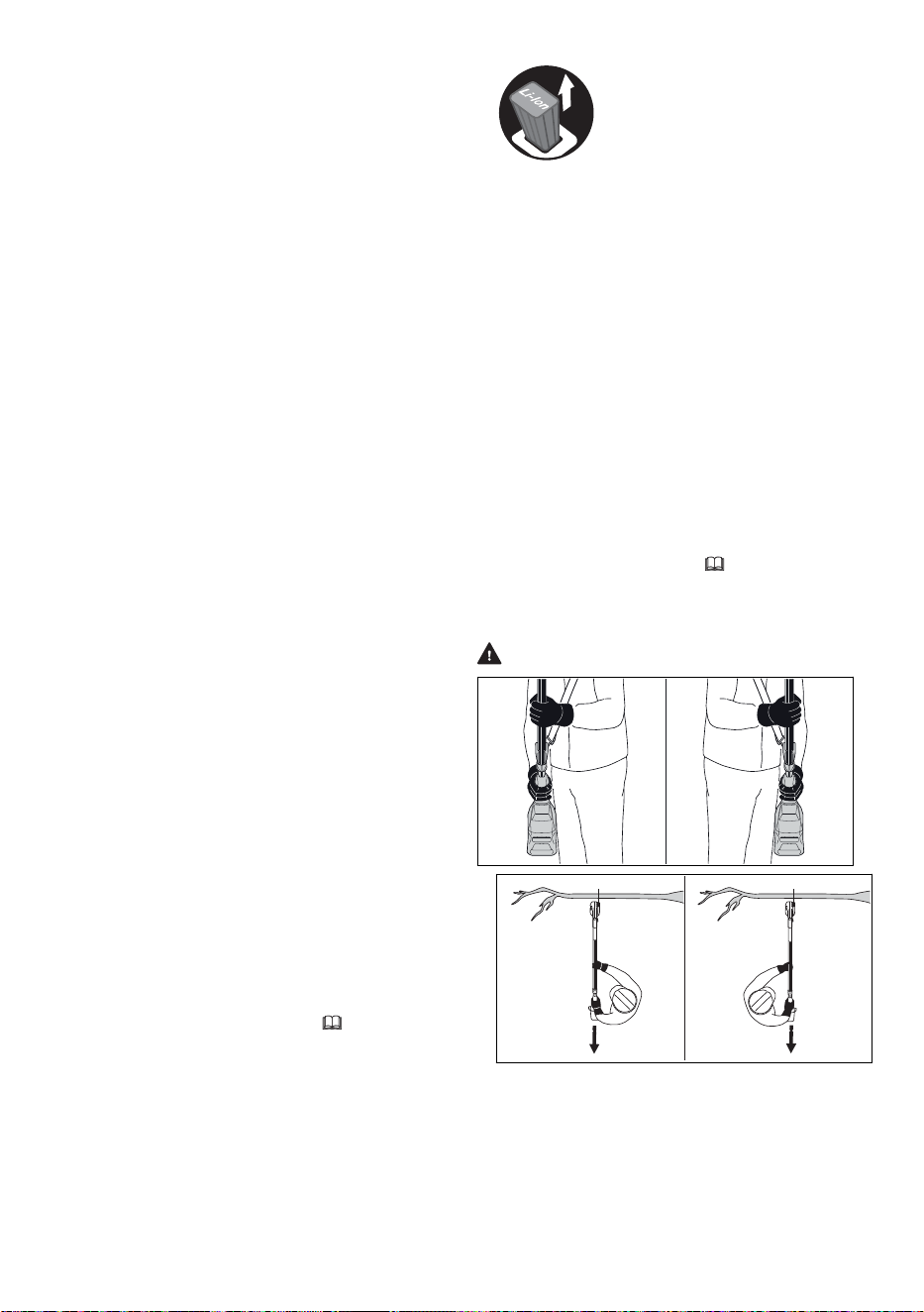
–
Compruebe la tensión de la cadena una vez
más después de ajustar la cubierta del
piñón de la cadena.
–
Compruebe la tensión de la cadena periódi‐
camente de allí en adelante y en intervalos
regulares (siempre después de quitar la
batería).
■
El uso de un podador de varilla que se ha
modificado, que está dañado, mal ajustado o
no se ha mantenido debidamente puede pro‐
vocar una avería y aumentar el riesgo de
lesiones graves o incluso mortales.
–
No utilice nunca un podador de varilla que
se haya modificado, que esté dañado o mal
mantenido, o que no se haya montado com‐
pletamente y de forma segura.
–
Siempre compruebe si su podador de varilla
está en buenas condiciones y si funciona
correctamente antes de iniciar los trabajos.
Preste especial atención al pestillo de reten‐
ción, a la palanca Ergo, al gatillo y al acce‐
sorio de corte.
–
Asegúrese de que el pestillo de retención,
la palanca Ergo y el gatillo se mueven libre‐
mente, y de que regresan a su lugar cuando
los suelta. El gatillo no debe poder opri‐
mirse si no se ha desbloqueado el pestillo
de retención.
–
Nunca intente modificar ni anular en modo
alguno los controles ni los dispositivos de
seguridad.
–
Si el podador de varilla o cualquiera de sus
piezas presenta daños o no funciona
correctamente, llévelo a su concesionario
de servicio STIHL autorizado. No use el
podador de varilla hasta que el problema se
haya solucionado.
■
Antes de colocar la batería:
–
Compruebe si hay corrosión o materias
extrañas en los contactos del comparti‐
miento de la batería. Manténgalos limpios.
–
Nunca inserte ni use una batería que esté
defectuosa, dañada, agrietada o defor‐
mada, o que pierda líquido.
–
Lea y siga las instrucciones de encendido
de la podadora de pértiga, 17.1.
■ Para reducir el riesgo de lesiones graves o
mortales provocadas por la activación acci‐
dental:
–
Suelte el gatillo y su bloqueo antes de inser‐
tar la batería.
–
Suelte el gatillo antes de retirar la batería.
–
Quite la batería antes de
armar, transportar, ajustar,
inspeccionar, limpiar, repa‐
rar, mantener o guardar el
podador de varilla, y siem‐
pre que no esté en uso.
–
Nunca deje el podador de varilla desaten‐
dido con la batería colocada.
–
Nunca guarde la batería en el podador de
varilla.
■ Antes de encender el podador de varilla, dé
los pasos que figuran a continuación para
reducir el riesgo de lesiones provocadas por
una pérdida de control o por un contacto acci‐
dental con la cadena:
–
Asegúrese de mantener la espada y la
cadena alejadas de su persona y de cual‐
quier otro tipo de obstáculo u objeto,
incluido el suelo.
–
Nunca intente arrancar el podador de varilla
mientras la espada está dentro de una
ranura de corte o entalla. Hacerlo podría
generar fuerzas reactivas y causar lesiones.
–
Lea y siga las instrucciones de encendido
del podador de varilla, 17.1.
6.5.2 Sujeción y control de la podadora de
pértiga
ADVERTENCIA
0000097178_001
■
0000-GXX-4803-A0
Para sujetar con firmeza y controlar correcta‐
mente el podador de varilla:
–
Mantenga los mangos limpios y secos en
todo momento. Protéjalos de la humedad,
del alquitrán, del aceite, de la grasa y de la
resina.
6 INSTRUCCIONES IMPORTANTES DE SEGURIDAD español / EE.UU
0458-698-8621-B 51

■ Para reducir el riesgo de lesiones graves o
mortales para el operador o los presentes por
pérdida de control:
–
Sujete siempre el podador de varilla firme‐
mente con las dos manos mientras trabaja,
agarrándolo por las superficies marcadas
para ello.
–
Agarre los mangos firmemente con todos
los dedos, manteniéndolos sujetos entre los
dedos índice y pulgar (vea las ilustracio‐
nes).
–
Coloque el podador de varilla de modo que
todas las partes de su cuerpo queden aleja‐
das del accesorio de corte siempre que la
batería esté en su lugar. Sitúese a la
izquierda o a la derecha del corte cuando
recorte ramas, fuera del plano de corte
(como se muestra en la ilustración).
–
Evite tocar cualquier objeto con el cua‐
drante superior de la punta de la espada.
Podría producirse un contragolpe.
–
Sujete el podador de varilla siempre firme‐
mente con ambas manos mientras trabaja.
–
Lea y respete todas las advertencias e ins‐
trucciones del capítulo "Contragolpe y otras
fuerzas reactivas", 7.
■
Si la máquina se maneja con una sola mano,
es más difícil resistir y absorber las fuerzas
reactivas (rechazo, tirón, contragolpe) sin per‐
der el control del podador de varilla. Además,
también es más difícil evitar que la espada y
la cadena reboten contra una rama. Para
reducir el riesgo de lesiones graves o mortales
para el operador o los presentes por la pér‐
dida de control:
–
Nunca intente manejar el podador de varilla
con una sola mano.
■ Para reducir el riesgo de que el operador o las
personas que se encuentren cerca sufran
lesiones graves o mortales causadas por una
pérdida de control, asegúrese de mantener el
equilibrio y los pies bien apoyados en todo
momento:
–
Nunca trabaje sobre una escalera de mano,
sobre un techo, un árbol o cualquier otro
punto de apoyo que no sea seguro.
–
Tenga especial cuidado cuando trabaje en
terrenos con mucha vegetación o húmedos,
y preste atención siempre a posibles obstá‐
culos ocultos como tocones, raíces, pie‐
dras, hoyos y zanjas, para evitar tropezarse
o caerse.
–
Proceda con extrema precaución cuando
trabaje en declives o en terrenos irregula‐
res.
–
Para no perder la estabilidad, retire siempre
las ramas caídas, los arbustos y el material
cortado, así como cualquier otro material,
objeto o vegetación que pueda aumentar el
riesgo de resbalarse, tropezarse o caer.
–
Proceda con mucho cuidado cuando corte
ramas, arbolitos y matorrales pequeños, ya
que el material fino y tierno puede enre‐
darse en la cadena y salir despedido hacia
usted o hacer que pierda el equilibrio.
–
No extienda los brazos más de lo necesa‐
rio. Mantenga el equilibrio y los pies bien
apoyados en todo momento.
–
Nunca arranque el podador de varilla mien‐
tras la espada está dentro de una ranura de
corte o entalla. Hacerlo podría generar fuer‐
zas reactivas y causar lesiones. En estos
casos, saque la espada del corte y vuelva a
introducirla con la máquina a velocidad
máxima, procurando no tocar ningún objeto
con la punta de la espada.
–
Si tiene un podador de varilla con tubo ajus‐
table, alargue el tubo solo lo necesario para
llevar a cabo el trabajo previsto, pero nunca
corte directamente por encima de su
cabeza. Asegúrese de que el podador de
varilla queda a un ángulo de no más de 60°
con respecto a la horizontal,
6.5.4.
■
Trabajar sosteniendo una máquina por encima
de los hombros puede resultar cansado. Para
reducir el riesgo de sufrir lesiones por efecto
de la fatiga:
–
Nunca sujete la máquina con la mano pos‐
terior colocada sobre el mango de control a
una altura superior a la de sus hombros.
–
Tómese descansos frecuentes.
■ El gancho está diseñado para proporcionar un
mayor control del podador de varilla durante el
corte. Si trabaja sin el gancho, el podador de
varilla podría tirar de usted bruscamente hacia
adelante. Esto podría causar una pérdida de
control o, si la punta de la espada golpea un
objeto, un contragolpe.
–
Para controlar mejor el podador de varilla,
trabaje siempre con el gancho.
■ Si se aplica presión al podador de varilla
cuando se llega al final de un corte, la espada
y la cadena en movimiento pueden saltar
fuera de la ranura de corte o de la entalla,
descontrolarse y golpear algún objeto. Para
reducir el riesgo de lesiones:
–
Tenga cuidado cuando se acerque al final
de un corte.
–
Nunca ejerza presión sobre la podadora de
pértiga cuando llegue al final de un corte.
español / EE.UU 6 INSTRUCCIONES IMPORTANTES DE SEGURIDAD
52 0458-698-8621-B

6.5.3 Condiciones de trabajo
ADVERTENCIA
■
Maneje el podador de varilla solo a la luz del
día y cuando las condiciones de visibilidad
sean buenas.
–
Aplace el trabajo si hace mal tiempo o
viento, si llueve o si hay niebla.
–
Nunca corte cerca de cables de alimenta‐
ción eléctrica.
■ Su podador de varilla es una máquina dise‐
ñada para ser manejada por una sola per‐
sona.
–
No permita que otras personas se acerquen
a la zona general de trabajo.
–
No se debe permitir la presencia de otras
personas, especialmente niños y animales,
en los lugares en los que se esté usando la
máquina.
–
Apague el motor inmediatamente si se le
aproxima alguna persona.
■ Para reducir el riesgo de lesiones al operador,
las personas que se encuentren cerca y usua‐
rios no autorizados:
–
Nunca deje el podador de varilla desaten‐
dido con la batería colocada.
–
Apague el podador de varilla y quite la bate‐
ría durante los descansos y siempre que el
podador de varilla no se utilice.
■
Las chispas que se generan durante el funcio‐
namiento del podador de varilla pueden
encender gases, líquidos, vapores, polvos u
otros materiales y sustancias combustibles.
Para reducir el riesgo de incendios y explosio‐
nes:
–
No utilice el podador de varilla en un lugar
donde haya gases, líquidos, vapores, pol‐
vos u otros materiales y sustancias com‐
bustibles.
–
Lea y respete las recomendaciones de las
autoridades gubernamentales (por ejemplo,
OSHA), para identificar y evitar los peligros
que representan los gases, líquidos, vapo‐
res o polvos combustibles, así como otros
materiales y sustancias combustibles.
■
Si una cadena en movimiento choca contra
una roca o contra otro objeto sólido, se pue‐
den producir chispas, lo que, en determinadas
circunstancias, puede encender materiales
inflamables. Entre los materiales inflamables
se incluyen, por ejemplo, la vegetación y los
arbustos secos, en particular cuando el clima
es cálido y seco.
–
Si existe riesgo de incendio leve o grave, no
use su podador de varilla cerca de materia‐
les inflamables, ni de vegetación o arbustos
secos.
–
Póngase en contacto con las autoridades
locales de control de incendios o con el ser‐
vicio forestal de los EE.UU. si tiene dudas
sobre si las condiciones de la vegetación y
del tiempo son adecuadas para el uso de
un podador de varilla.
■
El uso y el afilado de este podador de varilla
puede generar polvo, neblina de aceite y otras
sustancias que contienen productos químicos
considerados como causantes de enfermeda‐
des respiratorias, cáncer, defectos congénitos
u otros problemas reproductivos.
–
Consulte a agencias gubernamentales
como EPA, OSHA, CARB y NIOSH e infór‐
mese en otras fuentes autorizadas sobre
los materiales peligrosos si desconoce los
riesgos asociados con las sustancias con‐
cretas que va a cortar o con las que va a
trabajar.
■
La inhalación de determinados polvos, y espe‐
cialmente de polvos orgánicos como el moho
o el polen, puede provocar reacciones alérgi‐
cas o asmáticas en personas sensibles a
estas sustancias. La inhalación repetida o en
grandes cantidades de polvo o de otros conta‐
minantes suspendidos en el aire, y especial‐
mente de las partículas más pequeñas, puede
causar enfermedades respiratorias o de otro
tipo. Esto incluye el polvo de madera, espe‐
cialmente de maderas duras, pero también el
de algunas maderas blandas como la del
cedro rojo occidental.
–
Controle el polvo (como el aserrín), y las
neblinas (como la neblina de aceite cau‐
sada por la lubricación de la cadena) en su
punto de origen siempre que sea posible.
–
Trabaje siempre con una cadena debida‐
mente afilada que produzca virutas de
madera en vez de polvo fino.
–
En la medida de lo posible, utilice el poda‐
dor de varilla de modo que el viento o el
propio proceso de trabajo dirijan el polvo, la
neblina o cualquier otra sustancia particu‐
lada generada por el podador de varilla en
dirección contraria al operador.
–
Si no es posible mantener el polvo y otras
partículas inhalables a niveles de fondo o
aproximadamente de fondo, siempre utilice
una mascarilla aprobada por NIOSH que
reúna las características adecuadas para
las condiciones específicas de la zona de
trabajo. Siga las recomendaciones de las
entidades gubernamentales (por ejemplo,
6 INSTRUCCIONES IMPORTANTES DE SEGURIDAD español / EE.UU
0458-698-8621-B 53
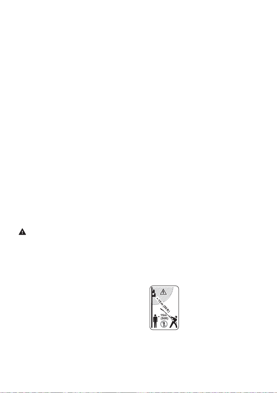
OSHA/NIOSH), y de las asociaciones labo‐
rales y comerciales.
■ Si la vegetación que corta o el terreno de los
alrededores están cubiertos por una sustancia
química, como pesticidas o herbicidas:
–
Lea y respete las instrucciones y las adver‐
tencias que se adjuntan con la sustancia
que se ha rociado sobre la vegetación o
sobre el suelo de los alrededores.
■
La aspiración del polvo de asbesto es peli‐
grosa y puede causar lesiones graves o mor‐
tales, enfermedades respiratorias o cáncer,
incluido el mesotelioma. El uso y la elimina‐
ción de productos que contienen asbesto
están estrictamente reglamentados por OSHA
y EPA.
–
No utilice su podador de varilla para cortar
ni modificar productos de asbesto o que
contengan asbesto.
–
Interrumpa el trabajo de inmediato y pón‐
gase en contacto con las autoridades esta‐
tales y locales competentes y/o con la EPA,
con su empresa o con el representante
local de OSHA, si tiene razones para creer
que está alterando asbesto.
■
El contacto repetido con aceite usado puede
causar cáncer de piel, y su utilización puede
ser perjudicial para el medio ambiente.
–
No use aceite de desecho para lubricar la
barra guía y la cadena del podador de vari‐
lla STIHL.
6.5.4 Instrucciones de manejo
ADVERTENCIA
■
Para reducir el riesgo de lesiones graves pro‐
vocadas por un arranque accidental de la
máquina:
–
Nunca toque la cadena con la mano ni con
ninguna otra parte del cuerpo cuando la
batería esté colocada, aunque la cadena no
esté girando.
■
Para reducir el riesgo de lesiones cortantes:
–
Mantenga las manos y los pies lejos de la
cadena de aserrado.
–
Nunca toque una cadena que esté en movi‐
miento con las manos ni con ninguna otra
parte del cuerpo.
–
Saque la máquina del corte siempre con la
cadena en marcha, para reducir el riesgo de
que el accesorio de corte quede atrapado.
–
Si la cadena se atasca, apague siempre el
motor, saque la batería y asegúrese de que
la cadena se ha detenido antes de proceder
a la limpieza.
–
Si la espada/cadena se engancha y queda
atrapada, apague el motor y saque la bate‐
ría antes de intentar liberar la espada.
–
No ejerza presión sobre el podador de vari‐
lla cuando esté llegando al final del corte.
La presión puede hacer que la espada y la
cadena en movimiento salten fuera de la
ranura de corte o de la entalla, que se des‐
controlen y que golpeen algún objeto.
■
La cadena continúa moviéndose durante un
periodo breve después de soltar por completo
el gatillo.
–
Espere a que la cadena se detenga antes
de caminar con el podador de varilla o de
ponerlo en el suelo.
■
En caso de emergencia:
–
Apague el motor de inmediato y retire la
batería.
■ El contacto con objetos extraños durante el
serrado puede provocar que la cadena se
rompa o salga despedida, o hacer que el
podador de varilla lance residuos peligrosos o
retroceda bruscamente hacia el operador.
Para reducir el riesgo de lesiones graves o
mortales provocadas por el contacto con obje‐
tos extraños:
–
Revise la rama antes de cortar.
–
Retire todos los objetos extraños para ase‐
gurarse de que la madera está libre de
materiales como clavos, puntas, cables o
alambres.
–
Antes de empezar a cortar, asegúrese de
que el corte se puede completar sin que la
máquina entre en contacto con objetos o
estructuras de los alrededores, como obras
de cantería o vallas.
■
La herramienta motorizada tiene un alcance
muy amplio. Para reducir el riesgo de que las
personas que se encuentran en los alrededo‐
res sufran lesiones graves o incluso mortales
causadas por la caída de objetos o por un
contacto accidental con el accesorio de corte:
–
Mantenga siempre una distan‐
cia de como mínimo 50 pies
(15 m) con respecto a otras
personas cuando use su herra‐
mienta motorizada.
–
No permita que otras personas se acerquen
a la zona general de trabajo.
■ Revise la cadena y la espada con frecuencia y
regularidad durante el trabajo, o inmediata‐
mente si nota cambios en el comportamiento
de corte:
español / EE.UU 6 INSTRUCCIONES IMPORTANTES DE SEGURIDAD
54 0458-698-8621-B
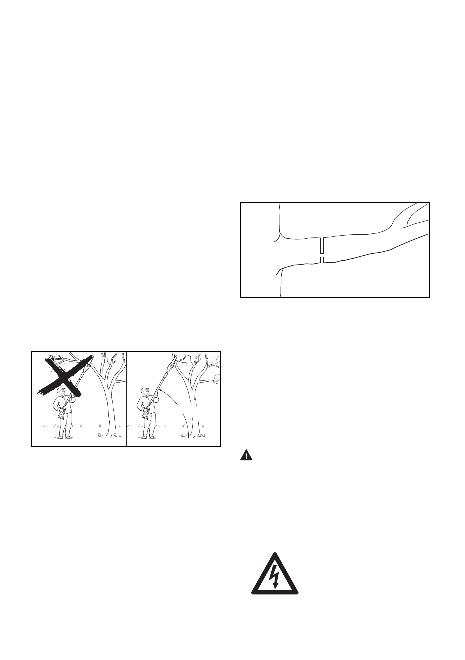
–
Apague el motor y quite la batería.
–
Revise el estado y la tensión de la cadena.
Compruebe si la cadena o la espada pre‐
sentan daños.
–
Si la cadena no se puede tensar correcta‐
mente, o si otros componentes del podador
de varilla están desgastados o dañados,
deje de trabajar inmediatamente y lleve su
podador de varilla a un concesionario de
servicio STIHL autorizado para que lo revi‐
sen, lo reparen o lo mantengan.
■
Si un árbol está podrido, puede romperse y
caer hacia el operador mientras este intenta
cortarlo. Para reducir el riesgo de lesiones
provocadas por la caída de residuos, dé los
pasos que figuran a continuación antes de
empezar a trabajar:
–
Tenga en cuenta el estado general del
árbol. Compruebe si se aprecian descom‐
posición o podredumbre en el tronco y en
las ramas. Compruebe si encuentra ramas
muertas que podrían llegar a desprenderse
a consecuencia de las vibraciones y caer
sobre el operador.
–
Para evitar que las ramas más grandes se
partan, haga un corte superficial en la parte
inferior de las ramas antes de practicar el
corte final desde arriba. Este procedimiento
le ayudará a reducir los daños en el árbol y
a predecir mejor cómo va a caer la rama.
max 60°
0000-GXX-4757-A2
■
Para reducir el riesgo de lesiones graves o
incluso mortales provocadas por la caída de
objetos:
–
Nunca corte una rama que esté directa‐
mente sobre su cabeza. Sujete el podador
de varilla a un ángulo de no más de 60° con
respecto a la horizontal (véase la ilustra‐
ción).
–
Nunca se coloque directamente debajo de
la rama que está cortando.
–
Preste atención a las ramas que caen. Pue‐
den caer objetos en direcciones inespera‐
das.
–
Establezca una vía de escape alejada de la
zona en que prevé que caerán las ramas.
–
En cuanto la rama recortada empiece a
caer, apártese y manténgase a una distan‐
cia adecuada.
–
Mantenga la zona de trabajo despejada y
libre de ramas caídas y obstáculos. Man‐
tenga todas las herramientas y equipos
fuera de la zona en que está trabajando y
de la ruta de salida.
■
Hay un mayor riesgo de que el podador de
varilla quede aprisionado cuando se cortan
ramas en tensión. La tensión en la madera
también se puede liberar repentinamente y
con gran fuerza, impulsar la rama o el poda‐
dor de varilla hacia el operador y provocar
lesiones o la pérdida del control sobre la
máquina.
2
1
0000-GXX-C576-A0
B
A
■
■ Para reducir el riesgo de lesiones graves o
mortales provocadas por una pérdida de con‐
trol cuando se corta madera bajo tensión:
–
Comience siempre con un corte de disten‐
sión (1) en el lado de compresión (A) de la
rama, y después haga un corte cruzado (2)
en el lado de tensión (B).
–
Si la espada/cadena se atasca y queda
aprisionada, apague el motor, quite la bate‐
ría y retire el podador de varilla de la rama,
prestando atención para que la rama no se
quiebre ni se desprenda de repente.
PELIGRO
■
La electricidad puede saltar de un punto a otro
formando arcos en el aire. Los niveles altos de
voltaje aumentan la distancia sobre la cual la
electricidad puede formar arcos. La electrici‐
dad también puede conducirse por las ramas
de un árbol, especialmente si estas están
húmedas. Para reducir el riesgo de electrocu‐
ción:
–
Nunca utilice este podador
de varilla cerca de alambres
o cables que puedan con‐
ducir corriente eléctrica.
Preste atención y com‐
pruebe si hay alambres o
cables ocultos antes de
empezar a trabajar.
6 INSTRUCCIONES IMPORTANTES DE SEGURIDAD español / EE.UU
0458-698-8621-B 55
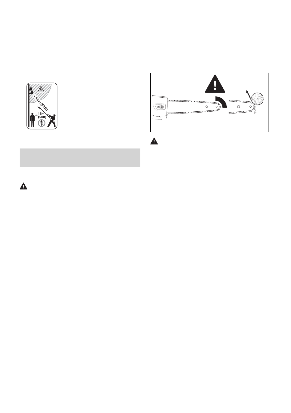
–
Nunca corte cerca de
cables de alimentación
eléctrica.
–
Sujete la herramienta moto‐
rizada únicamente por las
zonas de agarre marcadas,
pero no confíe en que estas
zonas lo van a proteger de
sufrir descargas eléctricas.
Este podador no está ais‐
lado.
–
Mantenga una distancia de al
menos 50 pies (15 m) entre el
podador de varilla (incluidas
las ramas con las que está en
contacto) y cualquier línea
eléctrica que esté bajo tensión.
–
Antes de trabajar a una distan‐
cia menor, póngase en con‐
tacto con la compañía eléctrica
y asegúrese de que se ha inte‐
rrumpido el suministro.
7 Contragolpe y otras fuer‐
zas reactivas
7.1 Fuerzas reactivas
ADVERTENCIA
■ Las fuerzas reactivas pueden producirse en
cualquier momento cuando la cadena está
girando. Las fuerzas reactivas pueden provo‐
car lesiones graves o mortales.
■
Las grandes fuerzas que se emplean para
cortar madera pueden cambiar de sentido y
volverse contra el operador. Si la cadena de
aserrado en movimiento pierde velocidad o se
detiene repentinamente al tocar un objeto
sólido, como un tronco o una rama, o si queda
aprisionada, se pueden generar inmediata‐
mente fuerzas reactivas.
■ Estas fuerzas reactivas pueden causar una
pérdida de control que, a su vez, puede provo‐
car lesiones graves o mortales.
–
Entender cuáles son las causas de estas
fuerzas reactivas le puede ser de gran
ayuda para evitar sorpresas y pérdidas de
control. El efecto sorpresa favorece los
accidentes.
■
Debido al diseño del podador de varilla, las
fuerzas reactivas que se producen cuando se
trabaja con él no son, por lo general, tan seve‐
ras como las que se producen con una moto‐
sierra.
–
Sin embargo, usted debe asegurarse de
que tiene la herramienta siempre correcta‐
mente sujeta, y los pies, bien apoyados,
para controlar el podador de varilla cuando
se produzcan este tipo de fuerzas.
Las fuerzas reactivas más frecuentes son:
–
Contragolpe
–
Tirón
–
Rechazo
7.2 Contragolpe
7.2.1 Contragolpe
0000097293_001
ADVERTENCIA
■ El contragolpe se puede producir cuando la
cadena en movimiento cerca del cuadrante
superior de la punta de la espada toca un
objeto sólido o queda aprisionada.
■
Cuando esto sucede, la energía que impulsa
la cadena puede generar una fuerza que
mueve el podador de varilla en la dirección
opuesta al sentido de giro de la cadena en el
punto en que la cadena se ralentiza o se
detiene. Esto puede provocar que la espada
se mueva hacia arriba.
7.2.2 Para evitar el contragolpe
La mejor forma de protegerse de las lesiones
que pueden resultar de un contragolpe es evitar
las situaciones de contragolpe:
1)
Tenga presente en todo momento la ubica‐
ción de la punta de la espada.
2)
Nunca deje que la punta de la espada haga
contacto con ningún objeto. No corte ramas
con la punta de la espada. Proceda con
especial cuidado cuando trabaje cerca de
vallas de alambre y cuando corte ramas
pequeñas, correosas, en las que la cadena
podría engancharse fácilmente.
3)
Corte solamente una rama a la vez.
español / EE.UU 7 Contragolpe y otras fuerzas reactivas
56 0458-698-8621-B
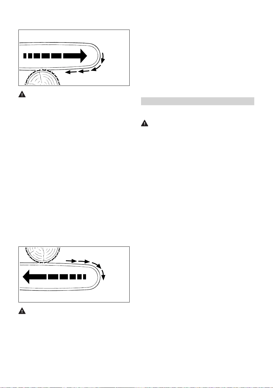
7.3 Tirón
0000-GXX-1348-A0
ADVERTENCIA
■ El tirón se produce cuando la cadena en la
parte inferior de la espada se detiene repenti‐
namente o se ralentiza de forma significativa
porque está aprisionada o atrapada, o porque
ha chocado contra algún objeto extraño en la
madera. La reacción de la cadena tira del
podador de varilla hacia adelante.
■
Normalmente, los tirones se producen cuando
la cadena no está rotando a su velocidad
máxima antes de entrar en contacto con la
madera.
■
Para reducir el riesgo de que se produzca un
tirón:
–
Manténgase alerta a las fuerzas o situacio‐
nes que puedan provocar que el material
aprisione la cadena de la parte inferior de la
espada.
–
Asegúrese de que la cadena gira a plena
velocidad siempre que inicie un corte.Ase‐
gúrese de que la cadena gira a plena velo‐
cidad siempre que inicie un corte.
7.4 Rechazo
0000-GXX-1349-A0
ADVERTENCIA
■
El rechazo se produce cuando la cadena de la
parte superior de la espada se detiene repen‐
tinamente o se ralentiza de forma significativa
tras quedar enganchada o atrapada, o tras
chocar contra algún objeto extraño oculto en
la madera. La reacción de la cadena puede
impulsar el podador de varilla repentinamente
hacia atrás, contra el operador.
■ Normalmente, el rechazo se produce cuando
se utiliza la parte superior de la espada para
cortar.
■
Para reducir el riesgo de rechazo:
–
Esté alerta a las fuerzas o situaciones que
puedan provocar que el material se engan‐
che o quede aprisionado en la parte supe‐
rior de la espada.
–
No corte más de una rama a la vez.
–
No tuerza la espada cuando la retire de un
corte por debajo, porque la cadena podría
quedar aprisionada o atascada.
8 Seguridad de la batería
8.1 Advertencias e instrucciones
ADVERTENCIA
■ Lea y respete las medidas de seguridad que
figuran en la batería, así como todas las
advertencias e instrucciones que se adjuntan
con ella.
■
El uso de baterías no autorizadas puede cau‐
sar daños en la herramienta motorizada y pro‐
vocar incendios, explosiones, lesiones perso‐
nales y daños materiales.
–
Use únicamente baterías auténticas de las
gamas AR o AP de STIHL con esta herra‐
mienta motorizada.
■
La utilización de baterías de las series AR o
AP de STIHL para cualquier fin que no sea ali‐
mentar los productos de STIHL podría ser
extremadamente peligroso.
–
Use las baterías de las gamas AR y AP de
STIHL solo para proporcionar alimentación
a productos de STIHL compatibles.
■
El uso de cargadores no autorizados puede
causar daños en la batería y provocar incen‐
dios, explosiones, lesiones y daños materia‐
les.
–
Para cargar las baterías de la serie AP de
STIHL, utilice siempre cargadores auténti‐
cos de las series AL 101, AL 301, AL 301-4
o AL 501 de STIHL.
–
Para cargar las baterías de mochila de la
serie AR de STIHL, utilice siempre cargado‐
res auténticos de las series AL 301,
AL 301-4 o AL 501 de STIHL.
■
La batería tiene funciones y dispositivos de
seguridad que, de dañarse, pueden provocar
que la batería genere calor, se agriete, pierda
líquido, se incendie o explote.
8 Seguridad de la batería español / EE.UU
0458-698-8621-B 57

–
Nunca permita que la tem‐
peratura de la batería
supere los 212 °F (100 °C).
–
Nunca prenda fuego a la
batería, ni la coloque sobre
o junto a fuegos, estufas u
otro tipo de objetos que
alcances temperaturas muy
altas.
–
Nunca use ni cargue una batería que no
funcione correctamente o que esté dañada,
agrietada, deformada o pierda líquido.
–
Nunca abra, desmonte ni golpee la batería;
no la deje caer ni la exponga a impactos
fuertes o a daños de cualquier otro tipo.
–
Nunca exponga la batería a microondas ni a
presiones elevadas.
–
Nunca introduzca objetos en las ranuras de
ventilación de la batería.
■ Las temperaturas extremas pueden hacer que
la batería genere calor, se rompa, pierda
líquido, se incendie o explote, lo que podría
causar lesiones graves o fatales y daños
materiales.
–
Nunca cargue, utilice o almacene la batería
fuera de los límites de temperatura
ambiente especificados, 26.6.
■
Para reducir el riesgo de que se produzcan
lesiones personales y daños materiales en
caso de que la batería humee, tenga un olor
inusual o se caliente más de lo habitual
durante el uso, la carga o el almacenamiento:
–
Deje de usar o de cargar la batería inmedia‐
tamente. Póngase en contacto con las auto‐
ridades en caso de incendio o explosión.
■
Para reducir el riesgo de que se produzca un
cortocircuito, que podría causar, a su vez, una
descarga eléctrica, un incendio o una explo‐
sión:
–
Asegúrese de mantener
secas las baterías de
mochila AR 1000, 2000 y
3000 de STIHL. Protéjalas
de la lluvia, del agua y de
otros líquidos. Fije la
cubierta para lluvia a la
batería antes de empezar a
trabajar bajo la lluvia o en
condiciones muy húmedas.
–
Si una batería de la gama
AP o AR L de STIHL ha
estado expuesta a la lluvia
durante el trabajo, sáquela
de la herramienta y déjela
secar bajo techo. Asegú‐
rese de que está completa‐
mente seca antes de car‐
garla o de usarla.
–
Nunca sumerja en agua ni
en ningún otro líquido una
batería de STIHL.
–
Nunca puentee las terminales de la batería
con alambres ni con otros objetos metáli‐
cos.
–
Cuando no la esté usando, mantenga la
batería alejada de objetos metálicos peque‐
ños capaces de conducir electricidad (p. ej.,
clips para papel, clavos, monedas, llaves).
–
Guarde la batería bajo techo, en un lugar
seco.
–
Nunca guarde la batería en entornos húme‐
dos o corrosivos, ni en condiciones que
puedan provocar corrosión en los compo‐
nentes metálicos.
–
Nunca guarde la batería en la herramienta
motorizada.
–
Cuando guarde la batería, mantenga una
carga del 40 % al 60 % para las baterías de
la serie AP de STIHL y una carga del 30 %
al 45 % para las baterías de la serie AR de
STIHL (2 LEDs verdes).
–
Si guarda la batería en el cargador, desco‐
necte el cargador del tomacorriente.
–
Proteja la batería de la exposición a produc‐
tos corrosivos, como las sustancias quími‐
cas utilizadas en el jardín o las sales des‐
congelantes.
–
Proteja la batería de la exposición a líquidos
conductores como el agua salada.
–
No intente reparar, abrir ni desmontar la
batería.
■ El líquido que contiene la batería, y que puede
derramarse en determinadas circunstancias,
es potencialmente nocivo y puede provocar
irritaciones en los ojos y en la piel, quemadu‐
ras químicas y otras lesiones graves.
–
Evite el contacto con la piel y con los ojos.
–
Para recoger el líquido de batería derra‐
mado, use un producto absorbente inerte,
como la arena.
–
En caso de contacto accidental, limpie
inmediatamente y a fondo la zona afectada
con un jabón suave y agua.
–
Si le entra líquido de batería en los ojos: no
se los frote. Enjuágese los ojos con agua
corriente durante al menos 15 minutos y
acuda al servicio médico más cercano.
■
Si la batería se prende fuego, puede resultar
peligrosa. Para reducir el riesgo de que se
produzcan lesiones personales graves y
daños materiales, en caso de incendio:
–
Evacue la zona. El fuego se puede extender
rápidamente. Manténgase lejos de cual‐
español / EE.UU 8 Seguridad de la batería
58 0458-698-8621-B

quier vapor que se genere y respete una
distancia de seguridad suficiente.
–
Avise a los bomberos.
–
Aunque se puede usar agua para apagar un
incendio de batería, es preferible utilizar un
extintor de incendios de polvo químico mul‐
tiuso.
–
Consulte al departamento de bomberos
sobre cómo desechar correctamente una
batería quemada.
9 Mantenimiento, reparación
y almacenamiento
9.1 Advertencias e instrucciones
ADVERTENCIA
■ Para reducir el riesgo de incendios, descargas
eléctricas o lesiones de otro tipo, así como de
daños materiales:
–
Respete rigurosamente las instrucciones de
limpieza y mantenimiento que se dan en las
secciones correspondientes de este manual
de instrucciones.
–
STIHL le recomienda que encargue la reali‐
zación de los trabajos de reparación a un
concesionario de servicio STIHL autorizado.
■
Un arranque accidental puede provocar lesio‐
nes o daños materiales. Para reducir el riesgo
de lesiones y de daños materiales provocados
por la activación accidental:
–
Quite la batería antes de
inspeccionar el podador de
varilla o de realizar alguna
tarea de limpieza, manteni‐
miento o reparación, antes
de guardarlo y cuando el
aparato no esté en uso.
■
Un mantenimiento adecuado ayudará a con‐
servar el rendimiento de corte y a reducir el
riesgo de lesiones provocadas por un desca‐
rrilamiento de la cadena o por las fuerzas
reactivas.
–
Siempre use guantes cuando manipule la
cadena de aserrado.
–
Mantenga la cadena, la espada y el piñón
limpios en todo momento.
–
Sustituya la cadena y la espada cuando se
desgasten o sufran daños.
–
Mantenga la cadena afilada y correcta‐
mente tensada.
–
Apriete todas las tuercas, pernos y tornillos
después de cada uso.
■ Lleve el podador de varilla inmediatamente a
mantenimiento si nota un cambio en sus
características de funcionamiento.
■
El uso de piezas no autorizadas o no aproba‐
das por STIHL puede provocar lesiones gra‐
ves o mortales, así como daños materiales.
–
Para llevar a cabo tareas de reparación o
mantenimiento, STIHL recomienda utilizar
únicamente piezas de repuesto STIHL idén‐
ticas a las originales.
■
Para reducir el riesgo de cortocircuitos e
incendios:
–
Mantenga las ranuras de la batería libres de
cuerpos extraños. Límpielas siempre que
sea necesario con un paño seco o con un
cepillo suave y seco.
■
Si no se almacenan correctamente, es posible
que el podador de varilla y la batería sean uti‐
lizados por personas no autorizadas, que
sufran daños y que aumente el riesgo de
incendios, de descarga eléctrica y de otro tipo
de lesiones o de daños materiales.
–
Retire la batería de la podadora de pértiga
antes de guardarla.
–
Nunca guarde la podadora de pértiga con la
batería puesta.
–
Cuando guarde la batería, mantenga una
carga del 40 % al 60 % para las baterías de
la serie AP de STIHL y una carga del 30 %
al 45 % para las baterías de la serie AR de
STIHL (2 LEDs verdes).
–
Si guarda la batería en el cargador, desco‐
necte el cargador del tomacorriente.
–
Guarde la podadora de pértiga y la batería
bajo techo, en un lugar seco y seguro al
que no puedan acceder niños ni otras per‐
sonas no autorizadas.
–
Nunca guarde la batería en la podadora de
pértiga ni en un contenedor con objetos
metálicos pequeños capaces de conducir
electricidad (por ejemplo, clips de papel,
clavos, monedas, llaves).
INDICACIÓN
■ Siempre destense la cadena cuando haya ter‐
minado el trabajo. Cuando se enfría, la
cadena se contrae. Si no se afloja, puede pro‐
vocar daños en el eje de transmisión y en los
cojinetes. Antes de volver a usar el podador
de varilla, no olvide tensar de nuevo correcta‐
mente la cadena.
9 Mantenimiento, reparación y almacenamiento español / EE.UU
0458-698-8621-B 59
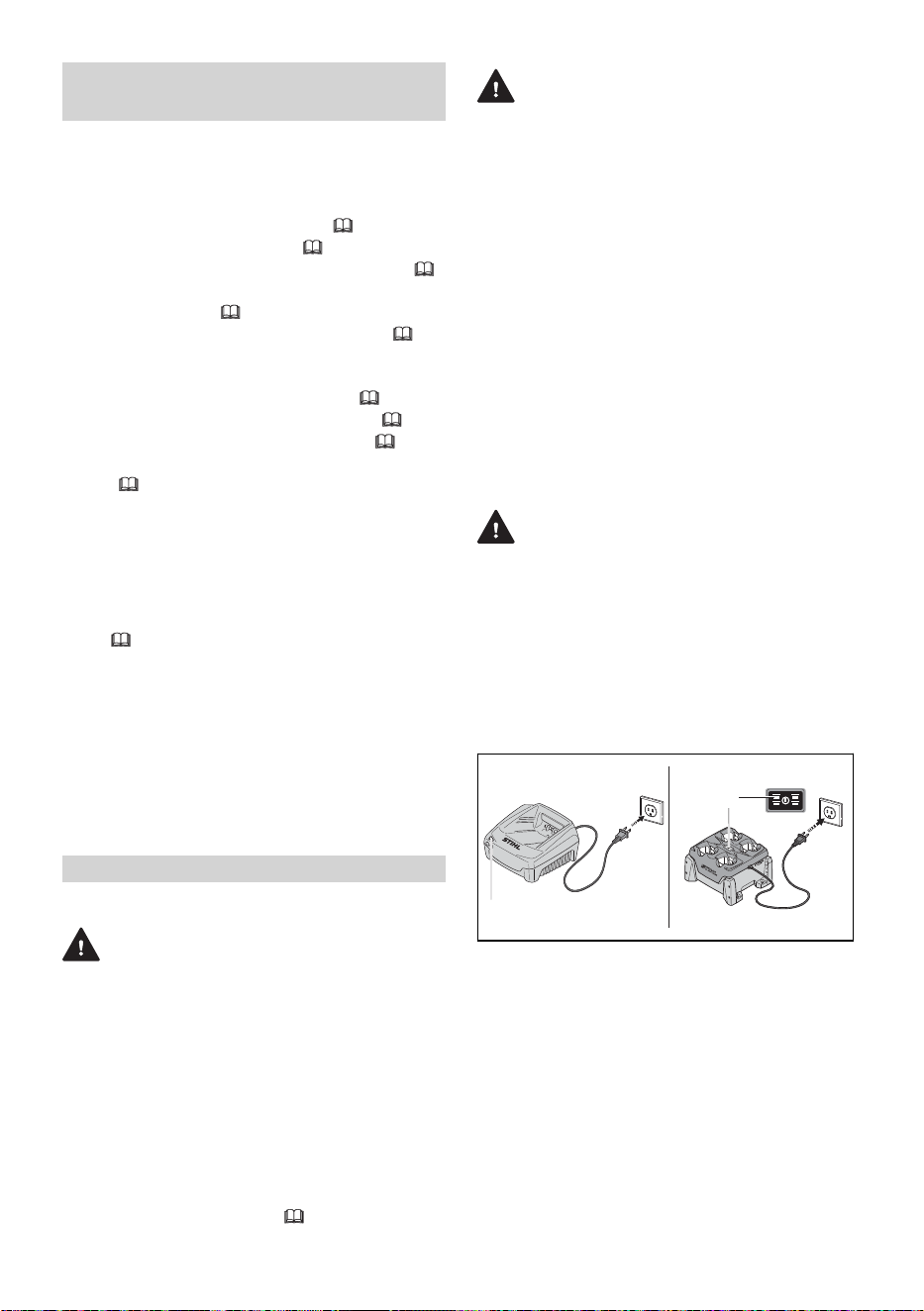
10 Antes de empezar a traba‐
jar
10.1 Preparación del podador de
varilla para el funcionamiento
Antes de empezar a trabajar:
►
Cargue por completo la batería,
11.
►
Monte el podador de varilla, 15.
►
Monte la espada y la cadena de aserrado,
15.6.
►
Tense la cadena, 15.7.
►
Llene el tanque de aceite de la cadena,
15.8.2.
► Compruebe si los controles funcionan correc‐
tamente y si están en buen estado, 18.1.
►
Revise el flujo de aceite de la cadena, 18.2.
►
Ajuste la longitud del tubo de mando, 19.1.
► Colóquese la correa para el hombro y ajús‐
tela, 19.3.
10.2 Conexión a la aplicación STIHL
connected
►
Encienda la interfaz de Bluetooth
®
de su dis‐
positivo móvil.
►
Encienda la interfaz de Bluetooth
®
de la bate‐
ría, 13.1
► Descargue la aplicación STIHL connected de
Google Play o de la App Store.
► Siga las instrucciones de la aplicación para
crear una nueva cuenta de usuario. Los usua‐
rios que ya hayan utilizado la aplicación deben
iniciar sesión con los datos de acceso de su
cuenta.
► Siga las instrucciones paso por paso para
añadir la batería a su lista de equipos.
11 Carga de la batería
11.1 Preparación del cargador
ADVERTENCIA
■ Lea y respete las precauciones de seguridad
dadas en la batería y en el cargador y todas
las advertencias e instrucciones que acompa‐
ñan a dichos productos. Para reducir el riesgo
de cortocircuito, que podría provocar una des‐
carga eléctrica, un incendio y una explosión,
asegúrese de que el cargador y sus compo‐
nentes estén secos y no estén dañados. Lea y
siga las advertencias e instrucciones en el
manual de su cargador. Para un rendimiento
óptimo, respete los rangos de temperatura
ambiente recomendados,
26.7.
ADVERTENCIA
■ Un circuito eléctrico doméstico típico suminis‐
tra entre 15 y 20 amperios. Un cargador
STIHL AL 501 consume aproximadamente
4.8 amperios. Un solo cargador AL 301 o
AL 301-4 consume aproximadamente
4.4 amperios, mientras que un AL 101 con‐
sume aproximadamente 1.3 amperios. Para
reducir el riesgo de incendios provocados por
la sobrecarga de un circuito eléctrico:
–
Asegúrese de que el sistema eléctrico tiene
capacidad suficiente para resistir el con‐
sumo eléctrico previsto antes de cargar la
batería.
–
Si tiene que cargar varias baterías, cárgue‐
las una a la vez o en circuitos separados, a
menos que tenga la certeza de que su cir‐
cuito resistirá el consumo total que necesi‐
tan todos los cargadores.
ADVERTENCIA
■ Dado que el cargador se calienta durante el
proceso de carga, no haga funcionar el carga‐
dor sobre superficies que puedan incendiarse
o en un lugar donde haya gases, líquidos,
vapores, polvo u otros materiales y sustancias
combustibles.
Para preparar el cargador para el funciona‐
miento:
3
2
4
1
1
2
3
4
0000082682_005
► Inserte el enchufe (3) en una toma de
corriente eléctrica (4) correctamente instalada
y que coincida con la tensión y la frecuencia
eléctrica indicadas en la placa de característi‐
cas del cargador.
El cargador ejecutará una autoprueba inmediata‐
mente después de enchufarlo. El LED del carga‐
dor (1) se iluminará en verde durante 1 segundo
aproximadamente, y luego en rojo por un lapso
breve hasta apagarse. Una vez que el LED se
apaga, la autoprueba ha finalizado y el cargador
está listo para cargar la batería.
español / EE.UU 10 Antes de empezar a trabajar
60 0458-698-8621-B
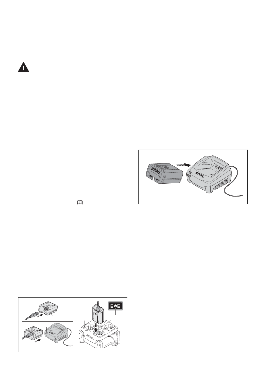
► Ubique el cable eléctrico (2) como para que
no se lo pise, cause tropiezos, esté en con‐
tacto con objetos cortantes o partes móviles o,
de otro modo esté sometido a daño o
esfuerzo.
11.2 Carga
ADVERTENCIA
■ Las baterías STIHL tienen características y
dispositivos de seguridad que, de dañarse,
pueden provocar que la batería genere calor,
se rompa, pierda líquido, se incendie o
explote. Nunca cargue una batería que fun‐
cione mal o que esté dañada, deformada o
tenga fugas, ni utilice un cargador averiado.
Nunca inserte una batería húmeda ni un adap‐
tador de batería que esté mojado. Nunca use
un cargador que esté mojado. Respete todas
las advertencias e instrucciones específicas
de su batería y de su cargador.
La batería no se suministra completamente car‐
gada de fábrica. STIHL le recomienda que car‐
gue la batería por completo antes de usarla por
primera vez.
Lea y siga las advertencias e instrucciones en el
manual de su cargador. Para un rendimiento
óptimo, respete los rangos de temperatura
ambiente recomendados,
26.7.
La batería se calienta durante el funcionamiento
de la herramienta motorizada. Si se conecta al
cargador una batería caliente, puede ser nece‐
sario esperar a que se enfríe para que empiece
a cargarse. El proceso de carga solo comienza
una vez que la batería se ha enfriado lo sufi‐
ciente.
El tiempo de carga depende de varios factores,
tales como el estado de la batería y la tempera‐
tura ambiente. Si quiere ver una lista completa
de los tiempos de carga aproximados, visite
www.stihl.com/charging-times.
Para cargar una batería AR:
3
1
3
4
5
4
5
2
0000081894_003
► Inserte el enchufe del cable de conexión (1)
en el tomacorriente (2) del ADA 100 (3), hasta
que se detenga.
► Inserte el ADA 100 en el cargador (5) hasta
que se detenga.
El LED (4) del cargador se ilumina en verde
cuando la batería se está cargando.
Los LED de la batería AR se iluminan en
verde e indican el estado de carga.
Cuando los LEDs de la batería se apagan, el
proceso de carga ha finalizado y el cargador
se apaga por sí solo. El ADA 100 se puede
retirar del cargador.
► Desenchufe el cable de alimentación del
tomacorriente cuando el cargador no se vaya
a usar durante un periodo prolongado.
► Cargue las baterías de mochila AR de STIHL
únicamente con cargadores auténticos de las
series AL 301, AL 301-4 o AL 501 de STIHL.
Para cargar una batería AP:
2
3
4
1
0000083481_002
► Inserte la batería (2) en el cargador (3) hasta
que haga tope.
El LED del cargador se ilumina en verde
cuando la batería se está cargando.
Los LED (1) de la batería AP se iluminan en
verde e indican el estado de la carga.
Cuando los LED de la batería se apagan, el
proceso de carga ha finalizado y el cargador
se apaga automáticamente. La batería AP se
puede retirar del cargador.
► Desenchufe el cable de alimentación del
tomacorriente cuando el cargador no se vaya
a usar durante un periodo prolongado.
► Cargue las baterías de la serie AP de STIHL
únicamente con cargadores auténticos de las
series AL 101, AL 301, AL 301-4 o AL 501 de
STIHL.
11 Carga de la batería español / EE.UU
0458-698-8621-B 61
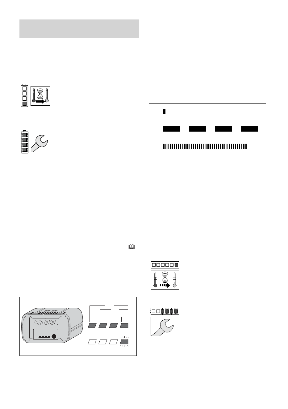
12 Diagnóstico por LED y
señales acústicas
12.1 Batería AP de STIHL
12.1.1 Estado de la batería
Cuatro LED muestran el estado de la batería.
Estos LED pueden encenderse o destellar en
verde o rojo.
Si un LED se enciende en rojo
continuamente, la batería está
demasiado caliente o demasiado
fría. Deje que la batería se
caliente o se enfríe gradualmente
a una temperatura ambiente de
aproximadamente 10 °C a 20 °C
(50 °F a 68 °F).
Si los cuatro LED destellan en
rojo: la batería está averiada y
debe reemplazarse. No intente
cargar, usar ni guardar la batería.
12.1.2 Estado de la herramienta motorizada
Los mismos LED en la batería indican el estado
de la herramienta motorizada.
Si tres LED se encienden en rojo continuamente,
el motor de la herramienta motorizada está
demasiado caliente. Deje que el motor se enfríe.
Si tres LED destellan en rojo cuando activa el
gatillo, la herramienta motorizada tiene un
defecto eléctrico. No utilice la herramienta moto‐
rizada. Solicite a un concesionario de servicio
STIHL autorizado que la revise antes de usarlo.
Para información de localización de averías,
25.
12.1.3 Estado de carga
Los LEDs en la batería también muestran el
estado de carga de la batería.
Para determinar el estado de carga de la batería:
0000079877_002
20-40%
40-60%
60-80%
80-100%
0-20%
1
► Presione el botón (1) en la batería.
Los LEDs de la batería se encenderán o des‐
tellarán en verde por unos 5 segundos e indi‐
carán el estado de carga (vea la ilustración).
Por ejemplo:
Si cuatro LED se encienden en verde continua‐
mente, la carga está completa.
Si un LED destella en verde, queda menos del
20 % de la carga.
12.2 Batería de mochila STIHL AR
12.2.1 Estado de la batería
Seis LED y una señal acústica denotan el estado
de la batería.
1
2
3
.......
0000-GXX-3229-A1
1 Un pitido breve
La señal acústica funciona como debe
hacerlo.
2 Cuatro o seis tonos largos (AR L)
La batería tiene poca carga. Recargue la
batería.
3 Sucesión rápida de pitidos breves
Hay una falla en la batería. La señal se
detiene automáticamente al cabo de unos
segundos. No intente cargar, usar ni guardar
la batería. Sustituya la batería.
Estos LED pueden encenderse o destellar en
verde o rojo.
Si un LED se enciende en rojo
continuamente, la batería está
demasiado caliente o demasiado
fría. Deje que la batería se
caliente o se enfríe gradualmente
a una temperatura ambiente de
aproximadamente 10 °C a 20 °C
(50 °F a 68 °F).
Si los cuatro LED derechos deste‐
llan en rojo y se escucha una
sucesión rápida de pitidos breves:
la batería está averiada y es
necesario reemplazarla. No
intente cargar, usar ni guardar la
batería.
► Sea consciente de que su capacidad para oír
la señal acústica puede verse disminuida si
usa protectores para oídos.
español / EE.UU 12 Diagnóstico por LED y señales acústicas
62 0458-698-8621-B
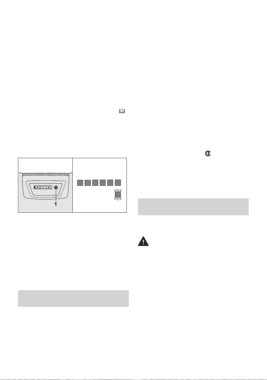
12.2.2 Estado de la herramienta motorizada
Cuando la batería está conectada con la herra‐
mienta motorizada, los mismos LED en la bate‐
ría indicarán el estado de la herramienta motori‐
zada.
Si tres LED se encienden en rojo continuamente,
el motor de la herramienta motorizada está
demasiado caliente. Deje que el motor se enfríe.
Si tres LED destellan en rojo cuando activa el
gatillo, la herramienta motorizada tiene un
defecto eléctrico. No utilice la herramienta moto‐
rizada. Solicite a un concesionario de servicio
STIHL autorizado que la revise antes de usarlo.
Para información de localización de averías,
25.
12.2.3 Estado de carga
Los LED y señales acústicas en la batería tam‐
bién muestran el estado de carga de la batería.
Para determinar el estado de carga de la batería:
0000-GXX-2673-A0
100 % 0 %
► Pulse el botón (1) en la batería tipo mochila.
Se escucha un pitido breve. Los LED de la bate‐
ría se encenderán o destellarán en verde por
unos 5 segundos e indicarán el estado de carga
(vea la ilustración).
Por ejemplo:
Si seis LED se encienden en verde continua‐
mente, la carga está completa.
Si un LED verde destella y se escuchan cuatro
pitidos largos: resta menos de un 20 % de carga.
13 Interfaz Bluetooth® de
Radio
13.1 Cómo activar la interfaz Blue‐
tooth
®
► Mantenga presionado el botón pulsador
durante aproximadamente 3 segundos.
Si el LED Bluetooth
®
junto al símbolo de
conectado se ilumina en azul durante aproxi‐
madamente 3 segundos, la interfaz Bluetooth
®
de la batería está activada.
13.2 Cómo desactivar la interfaz
Bluetooth
®
► Mantenga presionado el botón pulsador
durante aproximadamente 3 segundos.
Si el LED Bluetooth
®
parpadea en azul seis
veces, la interfaz Bluetooth
®
está desactivada.
13.3 Cómo restablecer la batería a
los ajustes de fábrica a través
de Bluetooth
®
(solo AP 300 S y
AP 500 S)
Restablecer la batería a los ajustes de fábrica
significa que se eliminarán todos los datos espe‐
cíficos del usuario.
► Presione el botón pulsador cuatro (4) veces
en rápida sucesión y manténgalo presionado
la cuarta vez hasta que el LED “BLUE‐
TOOTH®" junto al símbolo parpadee en
azul.
► Luego suelte el botón pulsador inmediata‐
mente.
► Conecte la batería a la aplicación STIHL con‐
nected para confirmar que se hayan eliminado
todos los datos específicos del usuario.
14 Batería de mochila STIHL
AR
14.1 Colocación y ajuste del cable
de conexión
ADVERTENCIA
■ Para reducir el riesgo de lesionarse por trope‐
zarse con el cable de conexión o por la pér‐
dida del control de la herramienta motorizada,
siempre asegure el cable por las guías pre‐
sentes en la mochila y con los cierres de
velcro, de la manera descrita a continuación:
Coloque y asegure el cable de conexión de
modo que no interfiera con las técnicas de tra‐
bajo adecuadas ni con su capacidad de man‐
tener el control de la herramienta motorizada.
13 Interfaz Bluetooth® de Radio español / EE.UU
0458-698-8621-B 63
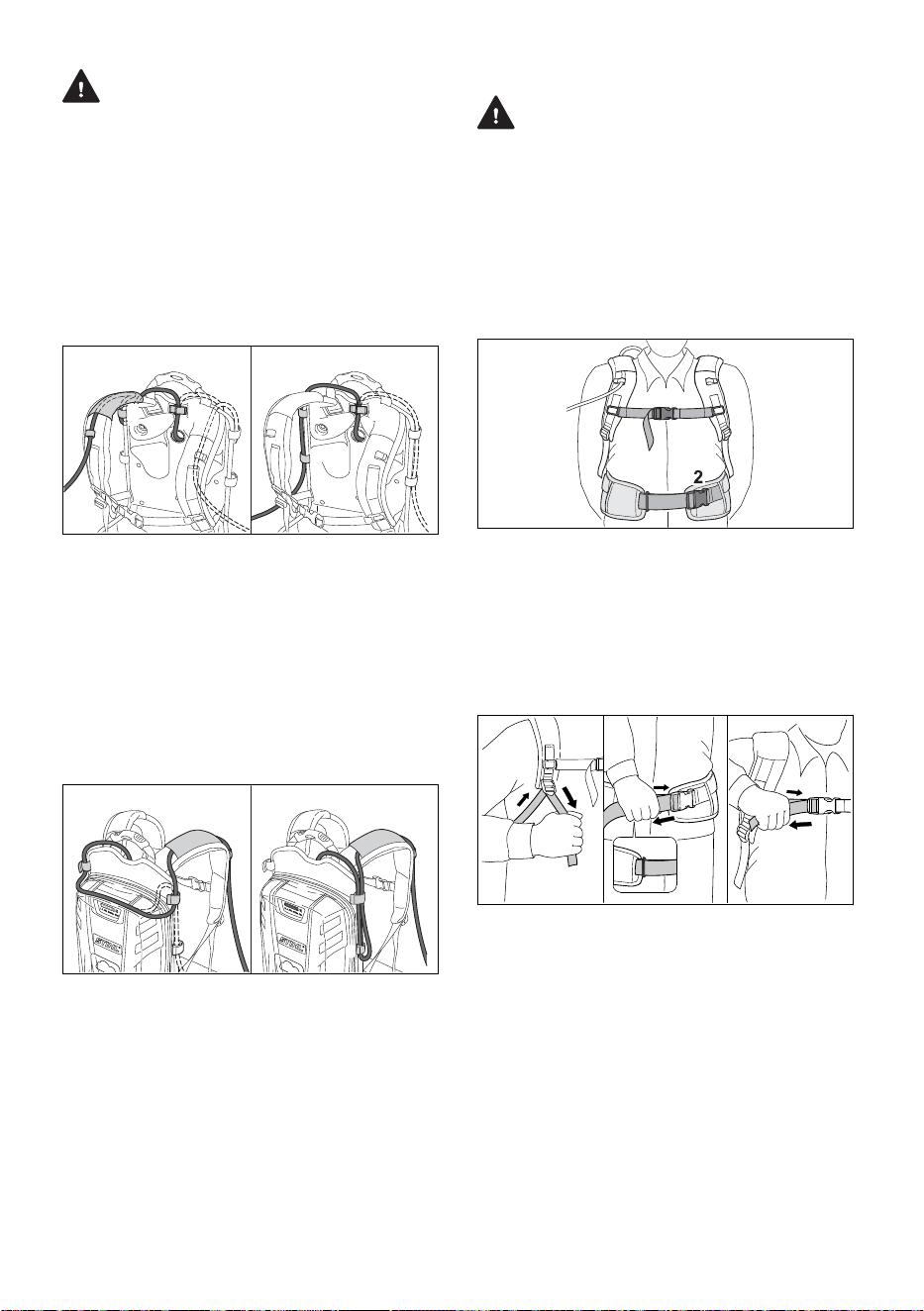
ADVERTENCIA
■ Coloque el cable de manera que se impida
que entre en contacto con el accesorio de
corte/trabajo o que se enganche en algún
objeto, lo cual podría hacerle perder el equili‐
brio o el control de la herramienta motorizada
y dar por resultado lesiones personales gra‐
ves y daños a la propiedad.
► Asegure el cable de conexión como se mues‐
tra a continuación y ajústelo para adaptarse a
la altura y el alcance del operador.
0000-GXX-2801-A2
1
1
1
1
1
1
B
A
► Pase el cable de conexión por las guías de la
correa para el hombro (ilustración A) o por la
placa trasera (ilustración B). Asegure el cable
de conexión al bastidor de la mochila con los
cierres de velcro (1). Siempre asegure el
cable de conexión utilizando la guía o los cie‐
rres de velcro hacia el mismo lado del cuerpo
en el cual se sujetará y controlará la herra‐
mienta motorizada. Asegúrese de que el cable
de conexión no cruza su tórax ni queda col‐
gando a un lado.
0000-GXX-2803-A1
D
C
► Si la longitud del cable de conexión es dema‐
siado larga, ajústela enroscando una parte del
cable en la parte superior (ilustración C) o a
un costado (ilustración D) de la batería de
mochila, y fijándolo con los cierres de velcro.
14.2 Colocación del arnés
ADVERTENCIA
■ Para reducir el riesgo de lesiones personales
en caso de una emergencia, el operador
deberá poder quitarse la batería de mochila
rápidamente. En caso de emergencia, desa‐
broche y quítese el cinturón y la tira de pecho
rápidamente, antes de dejar caer la batería al
suelo.
Para asegurar una colocación adecuada:
1
0000-GXX-7803-A0
► Colóquese la batería tipo mochila sobre la
espalda.
► Abroche y ajuste el cinturón (2) de modo que
repose de manera cómoda pero segura sobre
sus caderas.
► Abroche la tira para el pecho (1) y ajústela de
modo que quede cómoda pero segura por su
pecho.
0000-GXX-2815-A1
3
► Ajuste las tiras del arnés de modo que la
almohadilla de la placa quede firme y segura
contra su espalda.
► Pase el extremo del cinturón por dentro del
lazo (3).
► Para quitarse el arnés, desabroche las hebi‐
llas de soltado rápido del cinturón y de la tira
para el pecho y afloje las tiras del arnés por
medio de levantar los ajustadores deslizantes.
Para ayudar a reducir el riesgo de lesionarse en
caso de emergencia, practique la apertura rápida
del sujetador del cinturón y de la correa de
pecho, el soltado de las correas de hombro y
despojarse de la batería.
español / EE.UU 14 Batería de mochila STIHL AR
64 0458-698-8621-B
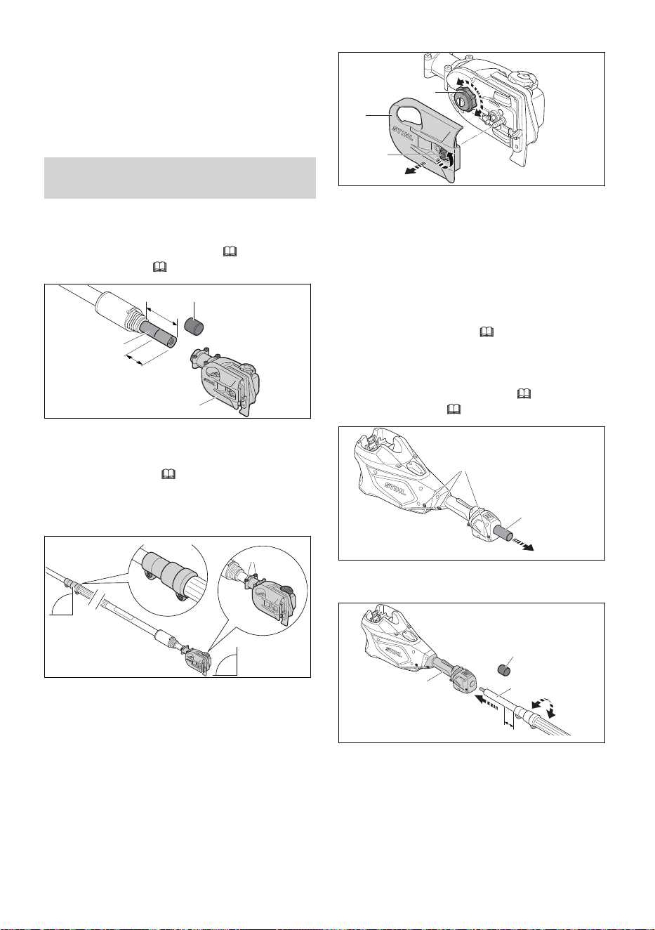
INDICACIÓN
■ Para evitar daños, coloque la batería suave‐
mente en el suelo cuando esté practicando.
No permita que la batería caiga al suelo ni la
lance.
15 Montaje del podador de
varilla
15.1 Montaje de la caja de engrana‐
jes
►
Apague el podador de varilla, 17.2.
►
Retire la batería, 16.2.
b
1
2
3
a
0000097972_001
► Retire la tapa (1) del extremo cuadrado del
tubo de mando (2).
► Ajuste la longitud del tubo de mando a
a = 3,9 in (10 cm),
19.1.
► Marque el tubo de mando en b = 2,4 in (6 cm).
► Encaje la caja de engranajes en el tubo de
mando, hasta la marca b.
90°
4
3
90°
5
0000098531_001
► Alinee el manguito de sujeción (4) y la caja de
engranajes (3) como se muestra en la figura.
Asegúrese de que los tornillos del manguito
de sujeción quedan en la parte inferior del
tubo de mando y de que la tapa de aceite de
la caja de engranajes queda hacia arriba.
► Apriete los tornillos (5).
7
6
8
0000098623_001
► Si la caja de engranajes no se puede encajar
en el tubo de mando hasta la marca b:
► Retire la cubierta del piñón de la cadena (6)
girando la tuerca (7) en sentido antihorario.
► Gire el piñón de la cadena (8) hasta que
pueda encajar la caja de engranajes en el
tubo de mando hasta la marca "b".
► Cambie la cubierta del piñón de la cadena y
asegure la tuerca después de montar la
espada y la cadena,
15.6.1.
15.2 Montaje de la carcasa del
motor
►
Apague el podador de varilla, 17.2.
►
Retire la batería, 16.2.
10
9
0000097324_001
► Afloje los tornillos (9).
► Retire el tubo protector (10).
11
12
2
0000097973_001
c
► Retire la tapa (11) del extremo redondo del
tubo de mando (2).
► Rote el tubo de mando hasta que se pueda
meter por la abertura del mango de con‐
trol (12). Para ello puede ser necesario rotar el
eje impulsor hacia delante y hacia atrás hasta
que los dos queden alineados.
► Deslícelo en dirección al mango de control
hasta que c = 0,8 in (2 cm).
15 Montaje del podador de varilla español / EE.UU
0458-698-8621-B 65
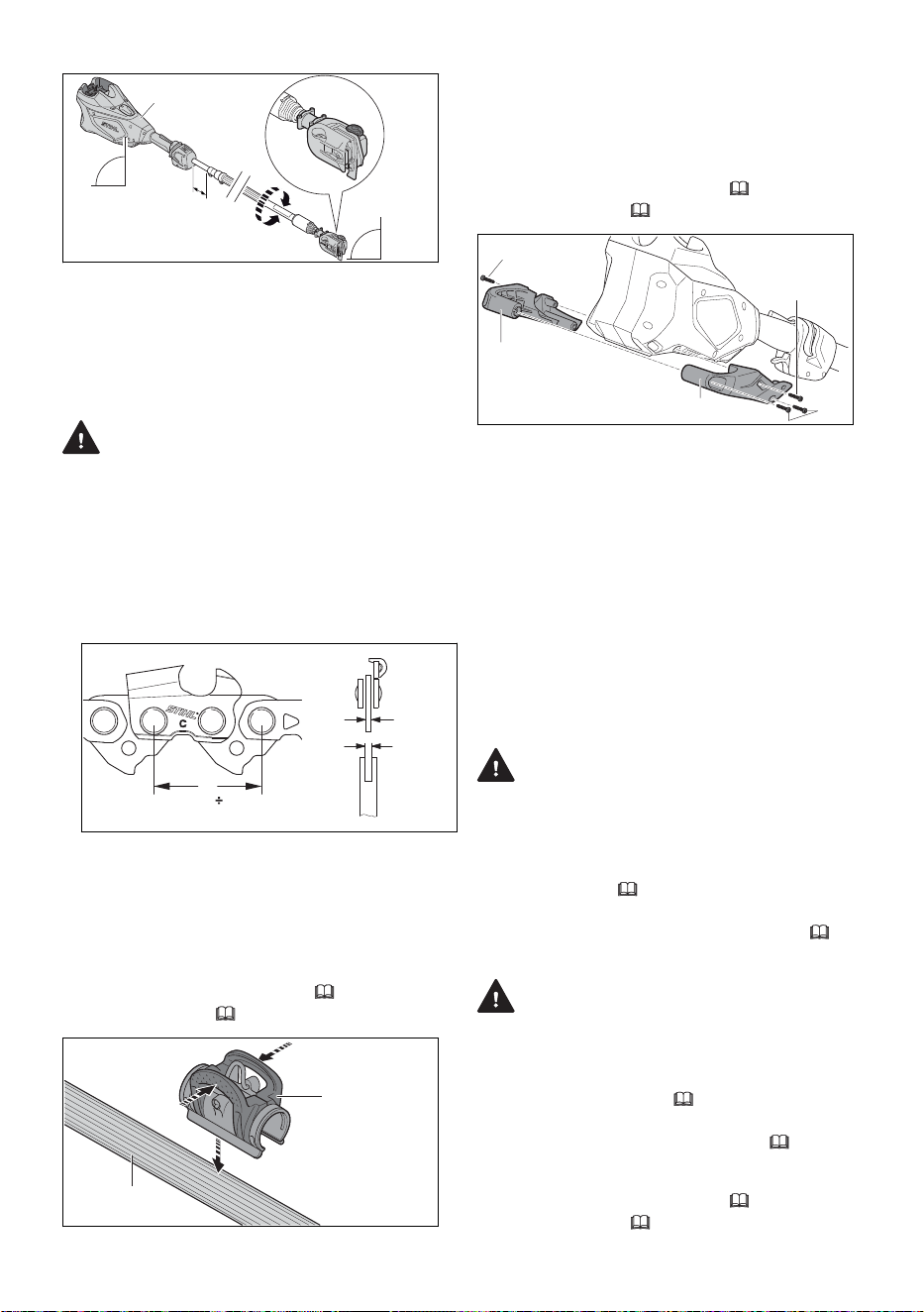
13
c
3
90°
90°
0000098532_001
► Alinee la carcasa del motor (13) y la caja de
engranajes (3) como se muestra en la ilustra‐
ción. Asegúrese de que la abertura de la bate‐
ría y la tapa de aceite quedan hacia arriba.
► Apriete los tornillos (9).
15.3 Accesorio de corte
ADVERTENCIA
■ Si no se utilizan los componentes correspon‐
dientes, el accesorio de corte se dañará de
manera permanente después de un período
breve de uso, y la cadena podría descarrilarse
y causar lesiones personales graves o fatales.
Un accesorio de corte consta de la cadena, la
espada y el piñón.
1
2
3
a
t = a 2
0000-GXX-1445-A0
–
El paso (t) de la cadena (1) deberá coincidir
con el paso del piñón.
–
El grueso del eslabón impulsor (2) de la
cadena de aserrado debe corresponder con
el ancho de la ranura de la espada (3).
15.4 Montaje de la pinza para arnés
►
Apague el podador de varilla,
17.2.
►
Retire la batería, 16.2.
1
2
0000097169_001
► Comprima la pinza para arnés (1) y colóquela
en el mango delantero (2).
15.5 Montaje del apoyo de la
máquina
►
Apague el podador de varilla,
17.2.
►
Retire la batería, 16.2.
5
2
1
4
3
0000097173_001
► Coloque la mitad izquierda del apoyo de la
máquina (1) contra el lado de la carcasa del
motor.
► Inserte el tornillo (2).
► Coloque la mitad derecha del apoyo de la
máquina (3) contra el lado de la carcasa del
motor.
► Inserte el tornillo (5).
► Inserte y apriete los tornillos (4).
► Apriete los tornillos (2) y (5).
15.6 Montaje y retiro de la espada y
la cadena de aserrado
15.6.1 Montaje de la espada y de la cadena
ADVERTENCIA
■ Antes de comenzar el montaje, asegúrese de
que ha retirado la batería. Nunca ponga en
funcionamiento el podador de varilla si la
espada y la cadena no se han montado
correctamente,
6.5. Use solo las combina‐
ciones de espada y cadena expresamente
recomendadas o aprobadas por STIHL,
6.4.
ADVERTENCIA
■ La cadena tiene muchos cortadores afilados.
Si entran en contacto con alguna parte de su
cuerpo, le causarán una herida, aunque la
cadena esté detenida,
6.4. Use guantes de
trabajo resistentes siempre que monte o mani‐
pule de cualquier modo la cadena, 6.3.
Para montar la espada y la cadena:
►
Apague el podador de varilla,
17.2.
►
Retire la batería, 16.2.
español / EE.UU 15 Montaje del podador de varilla
66 0458-698-8621-B
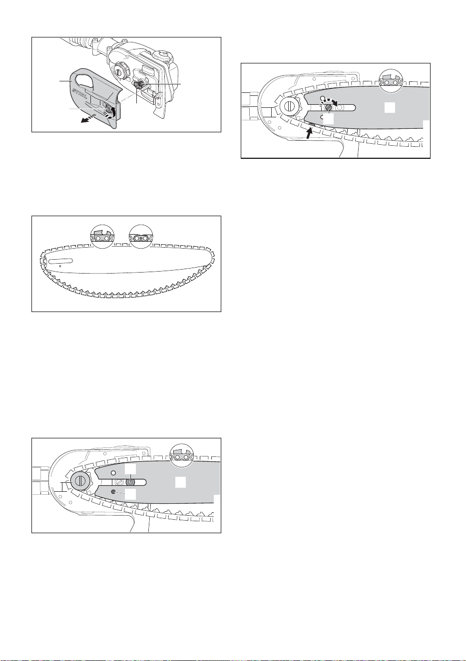
1
2
3
4
0000097170_001
► Gire la tuerca (1) en sentido contrahorario
hasta que se pueda retirar la cubierta del
piñón de la cadena (2).
► Quite la cubierta del piñón de la cadena.
► Gire el tensor lateral de la cadena (3) en sen‐
tido contrahorario hasta que el engranaje ten‐
sor (4) quede alineando contra la carcasa.
0000-GXX-2954-A0
► Coloque la cadena en la ranura de la espada,
empezando por la punta.
► Asegúrese de que los cortadores de la ranura
de la parte lateral superior de la espada que‐
dan orientados hacia la punta de la espada.
Las cadenas de STIHL llevan de fábrica unas
flechas en las correas que ayudan al operador
a determinar el sentido de giro correcto de la
cadena. Las flechas de las correas de amarre
de la parte superior de la espada deben que‐
dar orientadas hacia la punta de la barra.
6
7
5
8
0000097171_001
► No oriente la punta de la espada hacia el
piñón de la cadena (7).
► Coloque la cadena alrededor del piñón de la
cadena.
► Pase la espada (6) por el tornillo con
collar (5). La cabeza del tornillo con collar
debe sobresalir por el orificio oblongo.
► Encaje la clavija del engranaje tensor en el
orificio (8) de la espada.
0000097172_001
6
3
► Dirija los eslabones impulsores hacia la ranura
de la espada (6, flecha) mientras gira el tensor
lateral de la cadena (3) en sentido horario
hasta que se detenga.
La espada y la cadena deben estar montadas
en el podador de varilla de forma firme y
segura.
► Coloque la cubierta del piñón de la cadena en
el podador de varilla de modo que quede ali‐
neada con la carcasa.
► Gire la tuerca en sentido horario hasta que la
cubierta del piñón de la cadena quede firme‐
mente sujeta al podador de varilla.
15.6.2 Retiro de la espada y la cadena
► Desatornille la tuerca que suijeta la cubierta
del piñón de la cadena.
► Quite la cubierta del piñón de la cadena.
► Gire el tensor lateral de la cadena en sentido
contrahorario hasta que se detenga y la
cadena de aserrado se afloje.
► Retire la espada y la cadena
INDICACIÓN
■ Las partes superior e inferior de la espada son
simétricas y la espada debe montarse con la
impresión hacia arriba o hacia abajo. Girar la
espada cada vez que la cadena se afila o
cambia ayudará a reducir el desgaste despa‐
rejo y mejorar su vida útil.
15 Montaje del podador de varilla español / EE.UU
0458-698-8621-B 67
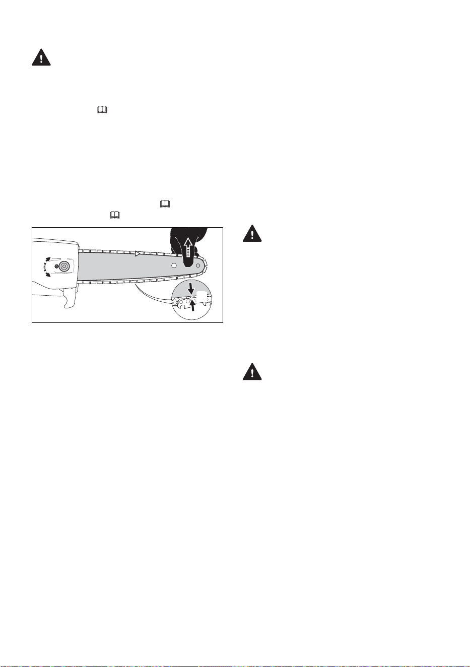
15.7 Tensado de la cadena
ADVERTENCIA
■ Para reducir el riesgo de lesiones personales
provocadas por un descarrilamiento de la
cadena, compruebe con frecuencia la tensión
de la cadena,
6.5. A las temperaturas de
funcionamiento, la cadena se dilata y se
comba. Las cadenas nuevas tienden a dila‐
tarse más que las que están más usadas.
Tense la cadena de modo que los eslabones
impulsores no puedan salirse de la ranura en
la parte inferior de la espada.
Para tensar correctamente la cadena:
►
Apague el podador de varilla, 17.2.
►
Retire la batería, 16.2.
0000-GXX-4761-A1
a
2
1
► Afloje la tuerca (1).
► Levante la punta de la espada.
► Gire el tensor lateral de la cadena (2) en sen‐
tido horario para apretar la cadena.
La cadena está bien ajustada cuando la dis‐
tancia (a) entre la parte inferior de la espada y
la cadena es de entre 0,04 in (1 mm) y 0,08 in
(2 mm), y cuando la cadena se puede despla‐
zar por la espada fácilmente tirando de ella
con la mano. Siempre use guantes cuando
manipule la cadena.
► Si la cadena no se puede mover a lo largo de
la espada, es que se ha tensado demasiado.
–
Reduzca la tensión girando el tensor lateral
de la cadena en sentido antihorario hasta
que la cadena se pueda mover libremente
por la espada.
–
Asegúrese de que los eslabones impulsores
permanecen dentro de la ranura y de que la
distancia (a) entre la parte inferior de la
espada y la cadena es de entre 0,04 in
(1 mm) y 0,08 in (2 mm).
► Una vez que la cadena esté tensada correcta‐
mente, levante la punta de la espada y apriete
la tuerca para asegurar la cubierta del piñón
de la cadena.
► Por último, asegúrese de que la distancia (a)
entre la parte inferior de la espada y la cadena
es de entre 0,04 in (1 mm) y 0,08 in (2 mm).
INDICACIÓN
■ Destense la cadena siempre cuando haya ter‐
minado el trabajo. Cuando se enfría, la
cadena se contrae. Si no se afloja, puede pro‐
vocar daños en el tubo impulsor y en los coji‐
netes. Antes de volver a usar el podador de
varilla, no olvide tensar de nuevo correcta‐
mente la cadena.
15.8 Lubricación de la cadena de
aserrado y de la espada
15.8.1 Lubricante de la espada y la cadena
ADVERTENCIA
■ Nunca use su podador de varilla si la espada
y la cadena no se lubrican. Si la cadena se
seca, el accesorio de corte sufrirá daños irre‐
parables en muy poco tiempo. Una cadena
dañada puede romperse y provocar lesiones
personales muy graves, incluso mortales.
Compruebe siempre la lubricación de la
cadena y el nivel de aceite del depósito antes
de empezar a trabajar, y con frecuencia mien‐
tras utiliza la motosierra.
ADVERTENCIA
■ Nunca use aceite de desecho para lubricar la
cadena de aserrado ni la espada. El contacto
repetido con aceite de deshecho puede cau‐
sar cáncer de piel. Además, el aceite de des‐
hecho es dañino para el medio ambiente.
El aceite para la espada y la cadena lubrica y
refrigera la cadena de aserrado mientras gira. La
vida de servicio de la cadena y de la espada
depende de la calidad del lubricante. Por eso, es
esencial usar únicamente un lubricante con una
fórmula específica para lubricar la cadena.
► Para que la cadena y la espada se lubriquen
de forma automática y fiable, use únicamente
un lubricante de calidad para la espada y la
cadena que no sea nocivo para el medio natu‐
ral. STIHL recomienda usar el aceite STIHL
BioPlus, que se biodegrada rápidamente.
español / EE.UU 15 Montaje del podador de varilla
68 0458-698-8621-B
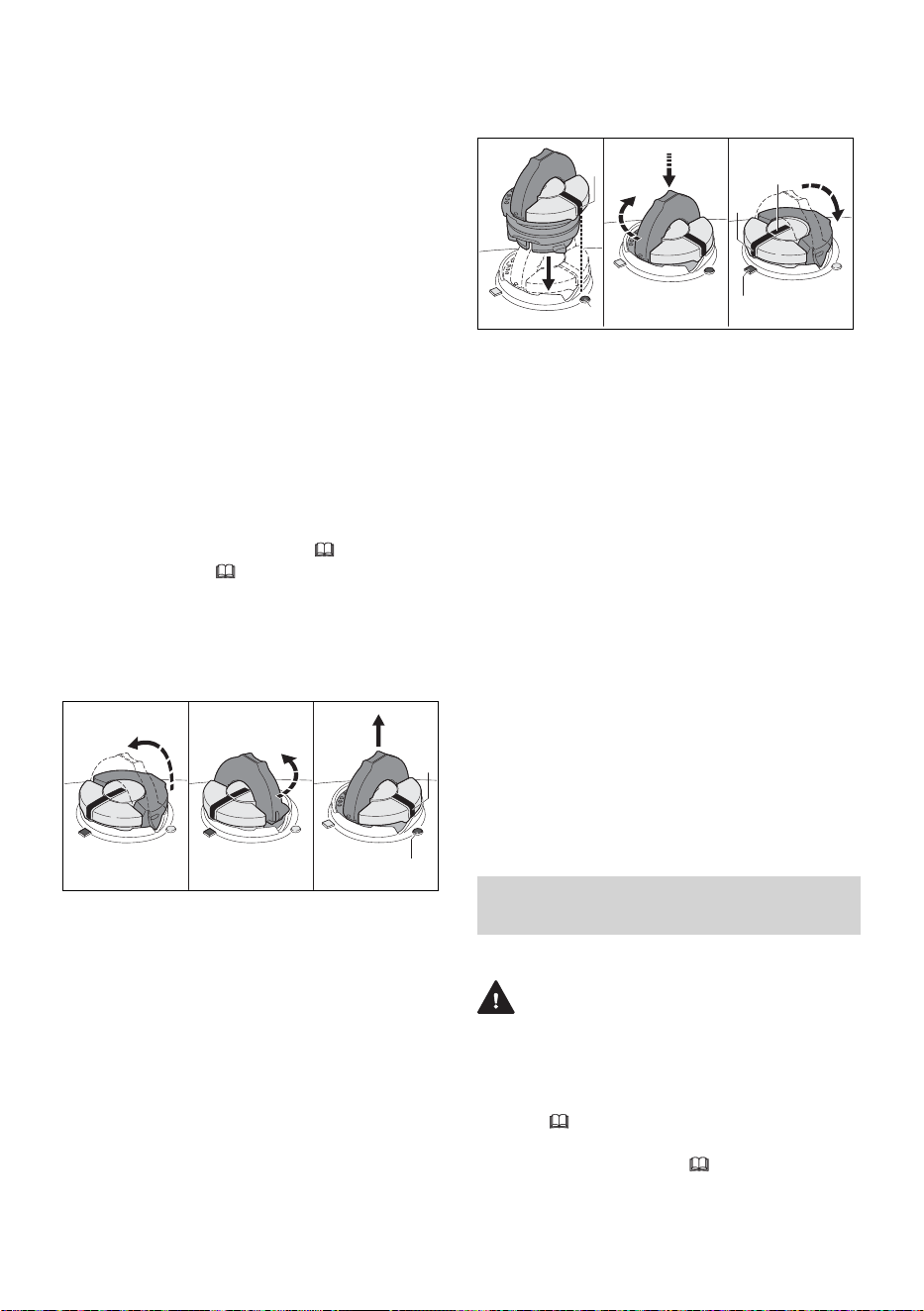
INDICACIÓN
■ El aceite de cadena biodegradable debe ser
resistente al envejecimiento, puesto que, de lo
contrario, se convertirá rápidamente en resina.
Si esto sucede, se forman depósitos duros
que son difíciles de eliminar, especialmente
en la zona de la cadena y de su acciona‐
miento. Incluso puede suceder que la bomba
de aceite se agarrote.
INDICACIÓN
■ El aceite de desecho no tiene las propiedades
de engrase necesarias, y no es adecuado
para la lubricación de la cadena.
15.8.2 Llenado del tanque de aceite de la
cadena
Apertura y llenado del tanque de aceite de la
cadena
Para llenar el tanque de aceite de la cadena:
►
Apague el podador de varilla, 17.2.
►
Retire la batería, 16.2.
► Coloque el podador de varilla sobre una
superficie nivelada de modo que la tapa de lle‐
nado de aceite quede hacia arriba.
► Limpie la zona alrededor de la tapa de llenado
de aceite con un paño levemente húmedo.
0000-GXX-2930-A1
123
4
5
► Levante el mango y presione la tapa firme‐
mente hacia abajo (1).
► Gire la tapa lentamente en sentido contrahora‐
rio (2) para colocarla en la posición
"abierta" (3). En la posición "abierta", la marca
de posición exterior (4) de la tapa quedará ali‐
neada con el símbolo (5) de la carcasa del
tanque de aceite de la cadena
► Retire la tapa y llene el tanque con aceite para
la espada y la cadena.
► Procure no derramar el aceite para la espada
y la cadena cuando llene el tanque.
► No llene el tanque en exceso. Deje aproxima‐
damente 0,5 in (13 mm) del tanque libres.
Cierre
Para cerrar el tanque:
2
3
1
0000-GXX-2931-A1
1
4
► Levante el mango de la parte superior de la
tapa de modo que quede a un ángulo de 90°.
Inserte la tapa en la abertura del tanque de
aceite de la cadena de modo que la marca de
posición exterior (1) quede alineada con el
símbolo "abierto" (2) de la carcasa del tanque
de aceite.
► Con ayuda del mango, apriete la tapa firme‐
mente hacia abajo y gírela en sentido horario
hasta que quede en la posición "cerrada"
(aproximadamente 1/4 de vuelta). En la posi‐
ción "cerrada", las marcas de posición inte‐
rior (4) y exterior (1) quedan alineadas con el
símbolo "cerrado" (3) de la carcasa del tanque
de aceite de cadena.
► Abata el mango de modo que quede alineado
con la parte superior de la tapa, y compruebe
que el cierre es estanco.
► Si el mango no se puede bajar de modo que
quede completamente alineado con la tapa, o
si el tope del mango no encaja en el hueco
correspondiente de la abertura del tanque, o si
la tapa queda floja, será porque la tapa no ha
quedado correctamente colocada, y tendrá
que repetir los pasos anteriores.
16 Colocación y extracción de
la batería.
16.1 Colocación de la batería
ADVERTENCIA
■ Para reducir el riesgo de incendios, descargas
eléctricas u otras lesiones personales o daños
a la propiedad, nunca utilice una batería ave‐
riada, dañada, con grietas, con fugas o defor‐
mada,
8. Nunca cargue, utilice o almacene
la batería fuera de los límites de temperatura
ambiente especificados, 26.6.
16 Colocación y extracción de la batería. español / EE.UU
0458-698-8621-B 69
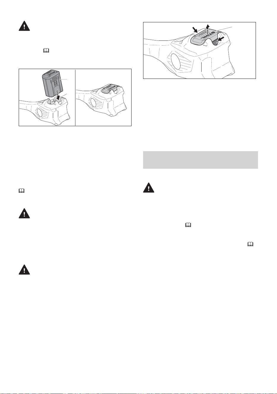
ADVERTENCIA
■ Para reducir el riesgo de activación accidental,
nunca guarde la batería en la podadora de
pértiga, 9.1.
Para colocar la batería:
1
2
0000097033-001
► Inserte la batería (1) en su compartimento (2),
hasta que haga tope.
La batería está colocada correctamente
cuando se escucha un chasquido. En esta
posición, hay contacto eléctrico entre la bate‐
ría y el podador de varilla.
Las baterías nuevas no están completamente
cargadas. Por eso, STIHL recomienda cargarlas
por completo antes de usarlas por primera vez,
11.
16.2 Extracción de la batería
ADVERTENCIA
■ Para reducir el riesgo de lesiones graves pro‐
vocadas por una activación accidental, retire
la batería siempre antes de armar, transportar,
ajustar, limpiar, reparar, mantener o guardar el
podador de varilla, y cuando no se esté
usando.
ADVERTENCIA
■ Saque la batería con cuidado, para evitar que
se caiga y provoque lesiones o daños materia‐
les.
Para quitar la batería:
► Suelte el disparador.
2
1
0000097034-001
► Apriete las palancas de bloqueo (1) para
sacar la batería (2) de su compartimiento.
INDICACIÓN
■ Evite exponer la batería a un calor excesivo o
a la luz solar directa durante períodos prolon‐
gados. El uso o el almacenamiento a tempera‐
turas no incluidas en el rango de temperatura
ambiente recomendado pueden reducir el ren‐
dimiento de la batería.
17 Encendido y apagado del
podador de varilla
17.1 Encendido
ADVERTENCIA
■ Nunca use su podador de varilla si se ha
modificado o si está dañado, mal ajustado o
mal mantenido, si no se ha montado por com‐
pleto y de forma segura o si no funciona
correctamente,
6.4. Para reducir el riesgo
de lesiones, use siempre ropa adecuada y
equipos de protección, incluidas gafas protec‐
toras, cuando utilice el podador de varilla,
6.3.
Antes de encender la máquina:
► Asegúrese de que no hay otras personas den‐
tro de la zona general de trabajo.
► Asegúrese de que tiene los pies bien apoya‐
dos.
► Mantenga una posición erguida.
► Sujete y maneje el podador de varilla siempre
agarrando con una mano firmemente el
mango de control y con la otra mano, el
mango delantero.
Para encender el podador de varilla:
español / EE.UU 17 Encendido y apagado del podador de varilla
70 0458-698-8621-B
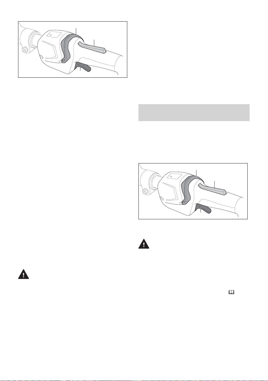
3
1
2
0000097175_001
► Apriete y mantenga presionado el bloqueo del
gatillo (1).
► Mientras mantiene apretado el bloqueo del
gatillo, deslice el pestillo de retención (2) hacia
adelante con el pulgar y suéltelo.
El LED se enciende.
► Apriete el gatillo (3) con el dedo índice.
La motosierra empezará a girar.
También puede desbloquear el disparador del
gatillo empujando el pestillo de retención hacia
delante y pulsando el bloqueo del disparador del
gatillo antes de que transcurran 5 segundos
(mientras el LED parpadee). Apriete el dispara‐
dor del gatillo con el dedo índice para encender
la cadena de sierra.
El motor no se encenderá a menos que se haya
apretado el bloqueo del disparador, se haya des‐
lizado el pestillo de retención hacia delante y se
haya oprimido el disparador.
Si el disparador y su bloqueo se sueltan, los LED
seguirán destellando durante aproximadamente
5 segundos. Mientras el LED destelle, la poda‐
dora de pértiga podrá encenderse de nuevo sin
necesidad de empujar hacia delante el pestillo
de retención.
Cuanto más apriete el disparador, más rápida‐
mente girará la cadena de sierra.
17.2 Apagado
ADVERTENCIA
■ La cadena de la motosierra seguirá rotando
brevemente una vez que usted haya soltado
el gatillo. Para evitar lesiones graves o incluso
mortales, evite el contacto con la cadena
cuando esta esté en movimiento. Para reducir
el riesgo de lesiones provocadas por una acti‐
vación accidental o por un uso no autorizado
de la herramienta, apague el motor, asegú‐
rese de que la cadena se ha detenido y retire
la batería antes de transportar el podador de
varilla o de posarlo en el suelo.
Para apagar el podador de varilla:
► Suelte el gatillo y su bloqueo, para que el gati‐
llo vuelva a la posición de bloqueo. En la posi‐
ción de bloqueo, el bloqueo del gatillo evita la
activación del gatillo. La activación del poda‐
dor de varilla también queda bloqueada elec‐
trónicamente por medio del pestillo de reten‐
ción una vez que los LED dejan de parpadear
(luego de aproximadamente 1 segundo).
La cadena de aserrado seguirá moviéndose
durante un periodo de tiempo breve una vez que
suelte el gatillo. Proceda con cuidado para evitar
el contacto después de soltar el gatillo y cuando
coloque el podador de varilla en el suelo.
18 Revisión del podador de
varilla
18.1 Prueba de los controles
Antes de comenzar a trabajar, confirme que el
bloqueo del gatillo (1), el pestillo de retención (2)
y el gatillo (3) están libres de daños y que funcio‐
nan correctamente.
3
1
2
0000097175_001
Bloqueo del gatillo (1), pestillo de retención (2) y
gatillo (3)
ADVERTENCIA
■ Para reducir el riesgo de lesiones graves o
mortales, mantenga las manos, los pies y
cualquier otra parte de su cuerpo alejados de
la cadena. No toque la cadena de aserrado
cuando esté colocada la batería. Nunca toque
la cadena en movimiento con las manos ni
con ninguna otra parte de su cuerpo,
6.5.2.
Asegúrese de que no hay otras personas a
una distancia de menos de 50 ft. (15 m) de la
zona de trabajo mientras prueba los controles.
Para probar los controles:
► Retire la batería.
18 Revisión del podador de varilla español / EE.UU
0458-698-8621-B 71
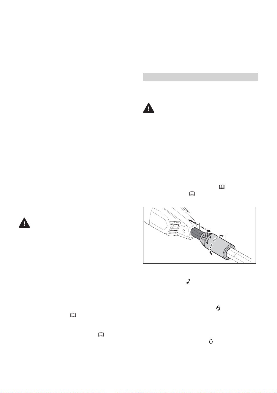
► Intente apretar el gatillo.
Si el gatillo se puede presionar sin desblo‐
quear antes el pestillo de retención, lleve el
podador de varilla a un concesionario de ser‐
vicio STIHL autorizado para que lo reparen
antes de utilizarlo.
► Oprima el bloqueo del gatillo y deslice el pesti‐
llo de retención hacia delante. Compruebe
que se mueven libremente y que al soltarlos
vuelven a su lugar por la acción de resorte.
► Coloque la batería.
► Sujete el podador de varilla agarrando firme‐
mente con una mano el mango de control y
con la otra mano, el mango delantero. Man‐
tenga oprimido el bloqueo del gatillo, deslice
el pestillo de retención hacia delante con el
pulgar y apriete el gatillo con el dedo índice.
El podador de varilla debería encenderse. Si
no se enciende, lleve el podador de varilla a
un concesionario de servicio STIHL autorizado
para que lo reparen antes de utilizarlo.
► Suelte el gatillo.
El podador de varilla debería apagarse.
Si el podador de varilla no se apaga cuando
suelta el gatillo, retire la batería y lleve el
podador de varilla a un concesionario de ser‐
vicio STIHL autorizado para que lo reparen
antes de volver a utilizarlo.
18.2 Comprobación de la lubricación
de la cadena
ADVERTENCIA
■ Nunca use su podador de varilla si la espada
y la cadena no se lubrican. Si la cadena se
seca, el accesorio de corte sufrirá daños irre‐
parables en muy poco tiempo. Una cadena
dañada puede romperse y provocar lesiones
personales muy graves, incluso mortales.
Compruebe siempre la lubricación de la
cadena y el nivel de aceite del tanque antes
de empezar a trabajar, y con frecuencia mien‐
tras utiliza la motosierra.
Para confirmar que el aceite de cadena está flu‐
yendo correctamente:
►
Coloque la batería,
16.1.
► Apunte con la espada hacia una superficie bri‐
llante.
►
Encienda el podador de varilla, 17.1.
La cadena debería desprender una pequeña
cantidad de aceite.
Si no se aprecian las gotas del aceite de
cadena, compruebe el nivel de aceite y añada
al tanque la cantidad que sea necesaria.
► Compruebe de nuevo la lubricación de la
cadena.
► Si aún no se ve aceite de lubricación de la
cadena, será porque el mecanismo de lubrica‐
ción no funciona correctamente. Lleve el
podador de varilla a un concesionario de ser‐
vicio STIHL autorizado para que lo reparen
antes de utilizarlo.
19 Durante el funcionamiento
19.1 Ajuste de la longitud del tubo
de mando
ADVERTENCIA
■ Para reducir el riesgo de lesiones causadas
por la pérdida del control sobre la máquina,
asegúrese de que el tubo de mando está ajus‐
tado correctamente y encajado en la posición
de bloqueo antes de empezar a trabajar.
La longitud del tubo de mando se puede ajustar
para adaptar el tubo a la altura y a la longitud de
los brazos del operador.
Para ajustar la longitud del tubo de mando:
►
Apague el podador de varilla, 17.2.
►
Retire la batería, 16.2.
► Sostenga el tubo de mando con firmeza.
2
1
0000097146_001
► Desbloquee el tubo de mando (2) girando la
tuerca de sujeción (1) media vuelta en direc‐
ción al símbolo .
► Ajuste la longitud del tubo de mando deslizán‐
dolo hasta la posición deseada.
► Bloquee el tubo de mando girando la tuerca
de sujeción hacia el símbolo y apretándola.
► Confirme que el tubo de mando está fijo en su
lugar.
► Si el tubo de mando aún se puede mover: blo‐
quee el tubo de mando girando la tuerca de
sujeción hacia el símbolo y apretándola
hasta que el tubo de mando quede fijo en su
lugar.
español / EE.UU 19 Durante el funcionamiento
72 0458-698-8621-B
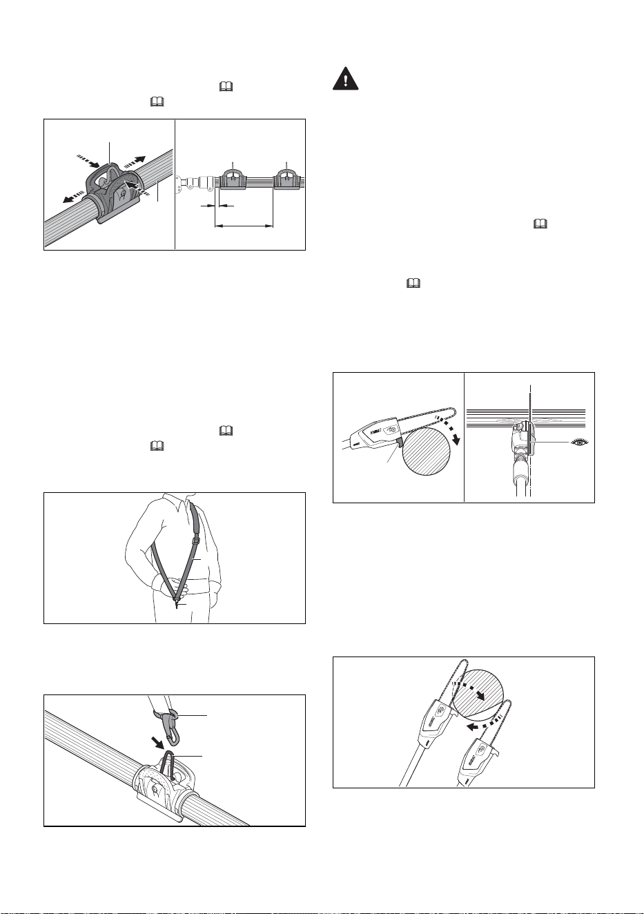
19.2 Alineación de la pinza para
arnés
►
Apague el podador de varilla, 17.2.
►
Retire la batería, 16.2.
a
b
2
1
0000097174_001
► Presione la pinza para arnés (1) y desplácela
por la empuñadura flexible (2) hasta alcanzar
las siguientes dimensiones:
–
Si el tubo de accionamiento está completa‐
mente retraído: a = 6 pulgadas. (15 cm).
–
Si el tubo de accionamiento está completa‐
mente extendido: b = 20 pulgadas. (50 cm).
19.3 Colocación y ajuste de la
correa para el hombro
Para colocar y ajustar el arnés:
►
Apague el podador de varilla, 17.2.
►
Retire la batería, 16.2.
► Colóquese la correa para el hombro sobre el
hombro.
2
1
0000-GXX-2990-A0
► Ajuste la longitud de la correa para el hom‐
bro (1) de modo que el mosquetón (2) quede
aproximadamente el ancho de una mano por
debajo de la altura de su cadera.
1
2
0000097177_001
► Enganche el mosquetón (1) a la pinza del
arnés (2) del podador de varilla.
19.4 Desrame
ADVERTENCIA
■ Para reducir el riesgo de lesiones graves o
incluso mortales provocadas por la caída de
objetos:
–
No corte en vertical por encima de usted.
Sujete el podador de varilla a un ángulo de
no más de 60° con respecto a la horizontal.
Pueden caer objetos en direcciones inespe‐
radas. No se coloque directamente debajo
de la rama que está cortando,
6.5.4.
–
Preste atención a las ramas que caen. En
cuanto la rama cortada empiece a caer,
apártese y manténgase a una distancia sufi‐
ciente,
6.5.4.
► Para que las ramas puedan caer sin obstácu‐
los, corte siempre en primer lugar las ramas
más bajas.
Corte transversal
1
0000085007_003
► Coloque el gancho (1) contra la rama.
La mira de desrame ayuda al operador a posi‐
cionar la barra y la cadena para el corte.
► Corte la rama con la máquina a velocidad
máxima, con la parte inferior de la espada.
Mantenga la punta de la barra guía alejada de
otras ramas, del suelo y de cualquier material
con hojas.
Corte de distensión
1
2
0000-GXX-4765-A1
► Si la rama está en tensión: practique un corte
de distensión (1) en la parte inferior y des‐
pués, el corte cruzado (2) desde el lado en
tensión.
19 Durante el funcionamiento español / EE.UU
0458-698-8621-B 73
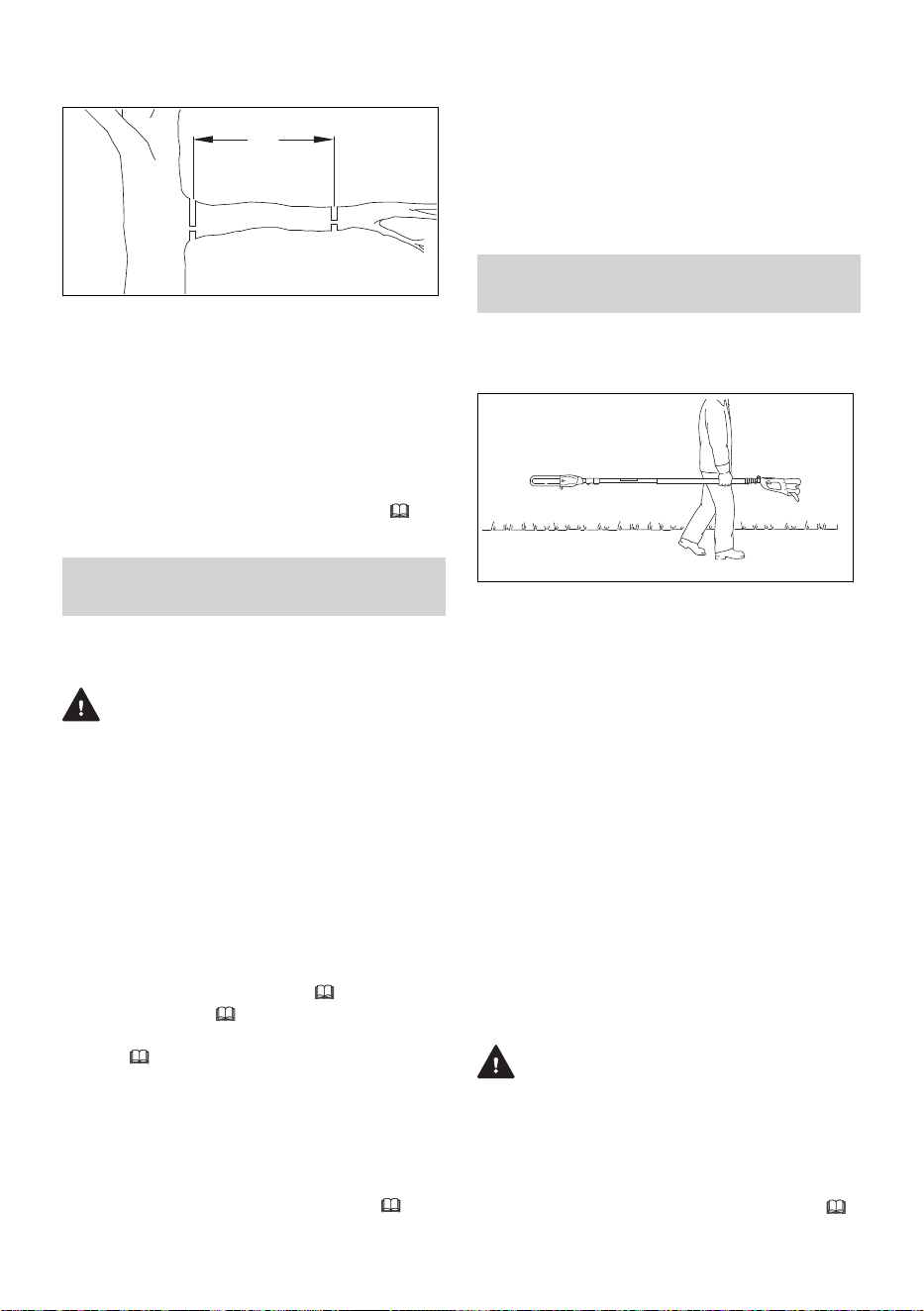
Corte de ramas gruesas
a
B
A
1
2
2
1
0000097743_001
► Acorte la rama practicando un corte de disten‐
sión (1) y después un corte cruzado (2) en el
punto de corte (A), a una distancia a = 8 in
(20 cm) del punto en que se va a practicar el
corte a ras (B).
► Haga el corte a ras, empezando con un corte
de distensión (1) y terminando con un corte
cruzado (2) en el punto de corte (B).
Para un rendimiento óptimo, respete los rangos
de temperatura ambiente recomendados,
26.7.
20 Después de completar el
trabajo
20.1 Preparación para el transporte
o el almacenamiento
ADVERTENCIA
■ Para reducir el riesgo de lesiones provocadas
por una activación accidental o por un uso no
autorizado, apague el podador de varilla y
retire la batería antes de transportar el poda‐
dor o de posarlo en el suelo. Para reducir el
riesgo de lesiones provocadas por los afilados
cortadores de la cadena, cubra siempre la
espada con la funda antes de transportar o de
guardar el podador de varilla.
Para preparar el podador de varilla antes de
transportarlo o de guardarlo:
►
Apague el podador de varilla,
17.2.
►
Retire la batería, 16.2.
► Ajuste el tubo de mando a la longitud más
corta, 19.1.
► Afloje la cadena.
► Deslice la vaina de la cadena por la barra de
modo que la cubra por completo.
► Si la batería o la podadora de pértiga se moja‐
ron o humedecieron durante el funciona‐
miento, déjelas secar por separado y por com‐
pleto antes de cargarlas o guardarlas,
26.7.
► Recuerde volver a tensar la cadena antes de
usar la podadora de pértiga.
INDICACIÓN
■ Cuando se enfría, la cadena se contrae. Si no
afloja la cadena tras terminar el trabajo, el
tubo impulsor y los cojinetes pueden sufrir
daños.
21 Transporte del podador de
varilla y de la batería
21.1 Podador de varilla
Cuando transporte el podador de varilla:
0000097742_001
► Coloque la funda de la cadena por la espada
de modo que la cubra por completo.
► Cuando transporte el podador de varilla a
mano, sujete el tubo de mando de modo que
el podador quede equilibrado en horizontal.
Mantenga el accesorio de corte detrás de
usted.
► Cuando transporte el podador de varilla en un
vehículo, cubra la espada con una funda de
cadena. Asegure y coloque el podador de
varilla de modo que se eviten vuelcos, golpes
y daños.
Con el podador de varilla se adjunta de serie
una funda de cadena compatible con el acceso‐
rio de corte. Si usa espadas de distintas longitu‐
des con su podador de varilla, cada una de las
fundas debe tener la longitud adecuada, para
reducir el riesgo de lesiones. La funda debe
cubrir toda la longitud de la espada.
21.2 Batería
ADVERTENCIA
■ Para reducir el riesgo de cortocircuito, que
podría generar una descarga eléctrica, un
incendio o una explosión, nunca transporte la
batería con objetos metálicos pequeños capa‐
ces de conducir electricidad (por ejemplo,
clips para papel, clavos, monedas, llaves),
8.
español / EE.UU 20 Después de completar el trabajo
74 0458-698-8621-B
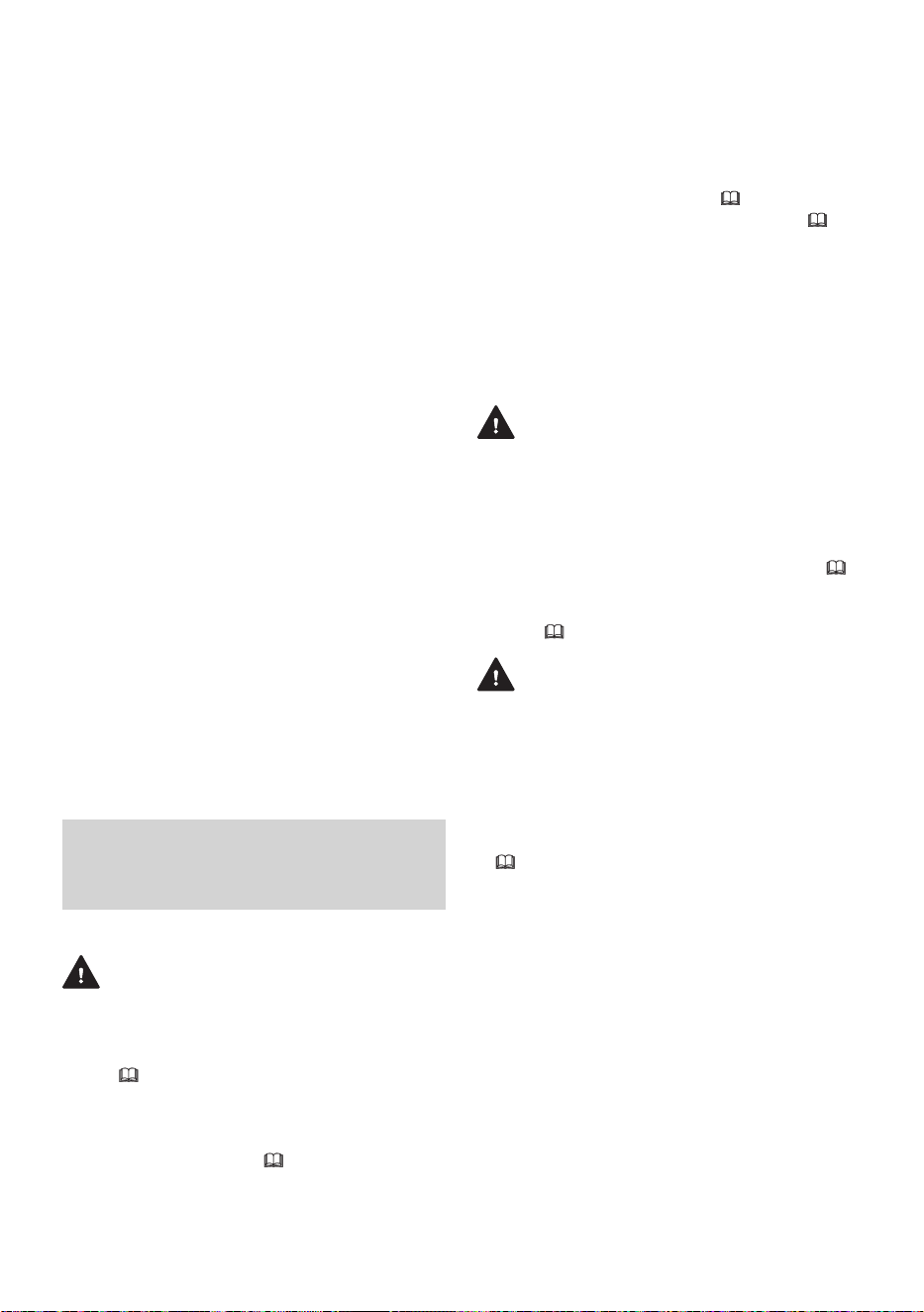
Al transportar la batería:
► Asegure la batería en un contenedor contra
golpes o daños. Nunca transporte la batería
con objetos metálicos pequeños capaces de
conducir electricidad (por ejemplo, clips de
papel, clavos, monedas, llaves).
► Si transporta la batería en un vehículo, asegú‐
rela junto con su contenedor para prevenir
vuelcos, impactos y daños.
Las baterías STIHL cumplen con los requisitos
establecidos en el Manual de las Naciones Uni‐
das de Pruebas y Criterios, Parte III, Subsección
38.3.
El transporte comercial por aire, agua y tierra de
celdas y baterías de iones de litio está regulado.
Esta batería está clasificada como un producto
UN 3480, Clase 9 y grupo de empaque II. Para
transportarla, ya sea como parte de la herra‐
mienta completa o sola, es necesario cumplir
con todas las normas de transporte correspon‐
dientes. Antes del transporte o traslado, consulte
con la empresa de transporte por tierra o agua, o
bien con la aerolínea de carga o pasajeros, para
determinar si el transporte está prohibido o
sujeto a restricciones o exenciones.
Por lo general, el usuario no necesita cumplir
con ninguna condición adicional para poder
transportar baterías STIHL por carretera hasta el
sitio donde se encuentra la herramienta eléc‐
trica. Verifique y respete cualquier norma espe‐
cial que pudiera aplicarse a su situación.
Para obtener más información, visite www.stih‐
lusa.com/battery-transportation-safety.
22 Almacenamiento del poda‐
dor de varilla y de la bate‐
ría
22.1 Podadora de pértiga
ADVERTENCIA
■ Guarde la podadora de pértiga bajo techo, en
un lugar seco y seguro al que no puedan
acceder niños ni otras personas no autoriza‐
das,
6.4. Nunca guarde la batería en la
podadora de pértiga. Un almacenamiento ina‐
decuado puede resultar en un uso no autori‐
zado de la podadora de pértiga y, por tanto,
en daños en el equipo,
6.4.
Si la podadora de pértiga va a permanecer guar‐
dada durante treinta días o más:
► Retire todas las virutas de madera y los restos
de suciedad del compartimento de la batería.
► Retire la cadena y la barra guía.
► Limpie la barra guía y rocíela con un disol‐
vente de resinas, como el lubricante y elimina‐
dor de resinas STIHL.
►
Limpie el podador de varilla,
23.1.
►
Llene el tanque de aceite de la cadena,
15.8.2.
► Asegure y coloque la podadora de pértiga de
modo que se eviten vuelcos, golpes y daños.
► Guarde la podadora de pértiga bajo techo, en
un lugar seco y seguro, fuera del alcance de
los niños y de otras personas no autorizadas.
22.2 Batería
ADVERTENCIA
■ Para reducir el riesgo de cortocircuito, que
podría generar una descarga eléctrica, un
incendio o una explosión, nunca guarde la
batería con objetos metálicos pequeños capa‐
ces de conducir electricidad (por ejemplo,
clips para papel, clavos, monedas, llaves),
8. Si la batería está húmeda o mojada, espere
a que se seque por completo antes de guar‐
darla,
8.
ADVERTENCIA
■ Las temperaturas extremas pueden dañar la
batería y provocar que esta genere calor, se
rompa, pierda líquido, se incendie o explote, lo
que podría causar lesiones personales graves
o fatales y daños materiales. Nunca cargue,
utilice o almacene la batería fuera de los lími‐
tes de temperatura ambiente especificados,
26.6.
Para almacenar correctamente la batería:
► Retire la batería de la podadora de pértiga.
► Cuando guarde la batería, mantenga una
carga del 40 % al 60 % para las baterías de la
serie AP de STIHL y una carga del 30 % al
45 % para las baterías de la serie AR de
STIHL (2 LEDs verdes).
► Si guarda la batería en el cargador, desco‐
necte el cargador del tomacorriente.
► Asegúrese de que la batería esté seca y guár‐
dela bajo techo, en un lugar seco y seguro.
► Asegúrese de que quede fuera del alcance de
los niños y de otras personas no autorizadas.
22 Almacenamiento del podador de varilla y de la batería español / EE.UU
0458-698-8621-B 75
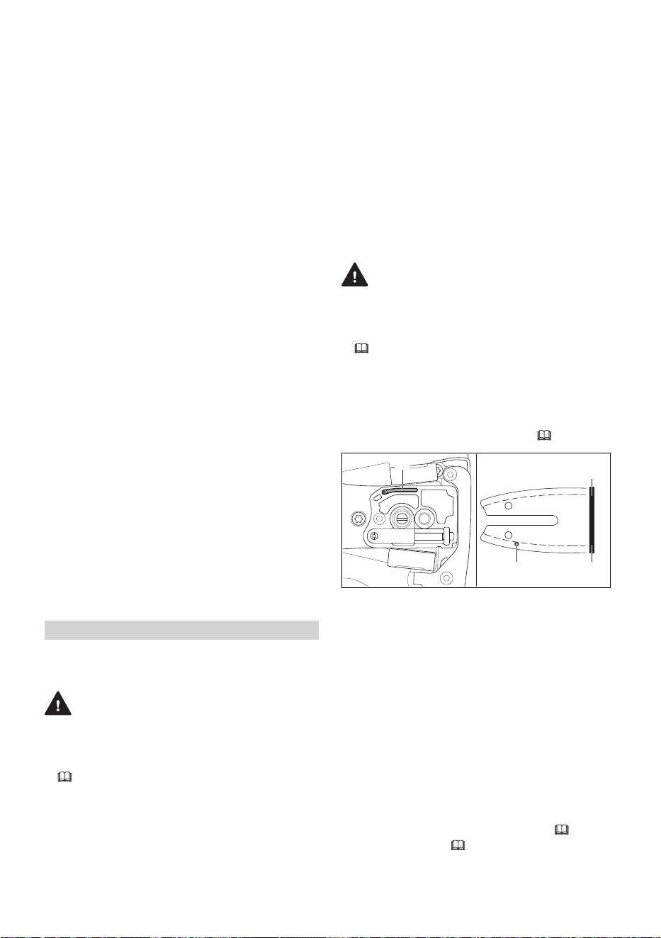
► Proteja la batería de la humedad y de los pro‐
ductos corrosivos, como las sustancias quími‐
cas utilizadas en el jardín o las sales descon‐
gelantes.
► Proteja la batería de la exposición a líquidos
conductores como el agua salada.
► Para alargar al máximo la vida útil de su bate‐
ría, guárdela a una temperatura ambiente de
entre 50 °F y 68 °F (10 °C y 20 °C), con un
nivel de carga de entre el 40 % y el 60 % para
las baterías de la serie STIHL AP y un nivel de
carga de entre el 30 % y el 45 % para las
baterías de la serie STIHL AR (2 LEDs ver‐
des).
► Las baterías de repuesto no deben permane‐
cer inutilizadas. Use todas sus baterías, por
turnos.
INDICACIÓN
■ Una batería que no se almacena correcta‐
mente puede sufrir una descarga profunda, lo
que puede provocar daños permanentes. Para
evitar una descarga profunda:
–
Retire la batería de la podadora de pértiga
después de terminar el trabajo.
–
Para alargar al máximo la vida útil de su
batería, guárdela con un nivel de carga de
entre el 40 % y el 60 % para las baterías de
la serie STIHL AP y un nivel de carga de
entre el 30 % y el 45 % para las baterías de
la serie STIHL AR (2 LEDs verdes).
–
Si guarda la batería en el cargador, desco‐
necte el cargador del tomacorriente.
–
Para obtener la máxima duración de la
batería, guárdela a una temperatura
ambiente de entre 50 °F y 68 °F (10 °C y
20 °C).
23 Limpieza
23.1 Limpieza de la podadora de
pértiga y de la batería
ADVERTENCIA
■ Para reducir el riesgo de lesiones provocadas
por una activación accidental, retire la batería
antes de realizar cualquier trabajo de limpieza,
9.
Para limpiar la podadora de pértiga y la batería:
► Limpie los componentes de polímero del
podador de varilla con un paño ligeramente
húmedo. No use detergentes ni disolventes.
Estos productos pueden dañar los componen‐
tes de polímero.
► Retire la cubierta del piñón y limpie la zona
alrededor del piñón con un trapo ligeramente
húmedo o con un disolvente de resina, como
el eliminador de resina y lubricante de STIHL.
► No utilice una hidrolavadora para limpiar el
podador de varilla, ni la rocíe con agua ni con
otros líquidos.
► Mantenga la carcasa y las guías de la batería
libres de cuerpos extraños, y límpielas siem‐
pre que sea necesario con un cepillo blando o
con un paño suave y seco.
23.2 Limpieza de la espada y de la
cadena de aserrado
ADVERTENCIA
■ Para reducir el riesgo de lesiones provocadas
por una activación accidental, retire la batería
antes de realizar cualquier trabajo de limpieza,
9. Para evitar lesiones, lleve guantes de
trabajo resistentes siempre que manipule la
cadena.
Para limpiar correctamente la espada y la
cadena:
►
Retire la barra guía y la cadena, 15.6.2.
3
1
2
3
0000097134_001
► Limpie el conducto de salida de aceite (1), el
orificio de entrada de aceite (2) y la ranura (3)
con un cepillo, con un paño ligeramente
húmedo o con un disolvente de resinas, como
el lubricante y eliminador de resinas STIHL.
No use detergentes.
► Limpie la cadena con un cepillo, con un paño
ligeramente húmedo o con un disolvente de
resinas. No use detergentes.
► No utilice una hidrolavadora para limpiar la
espada o la cadena, ni las rocíe con agua ni
con otros líquidos.
23.3 Limpieza del filtro de aire
Para limpiar el filtro de aire:
►
Apague la herramienta motorizada,
17.2.
►
Retire la batería, 16.2.
español / EE.UU 23 Limpieza
76 0458-698-8621-B
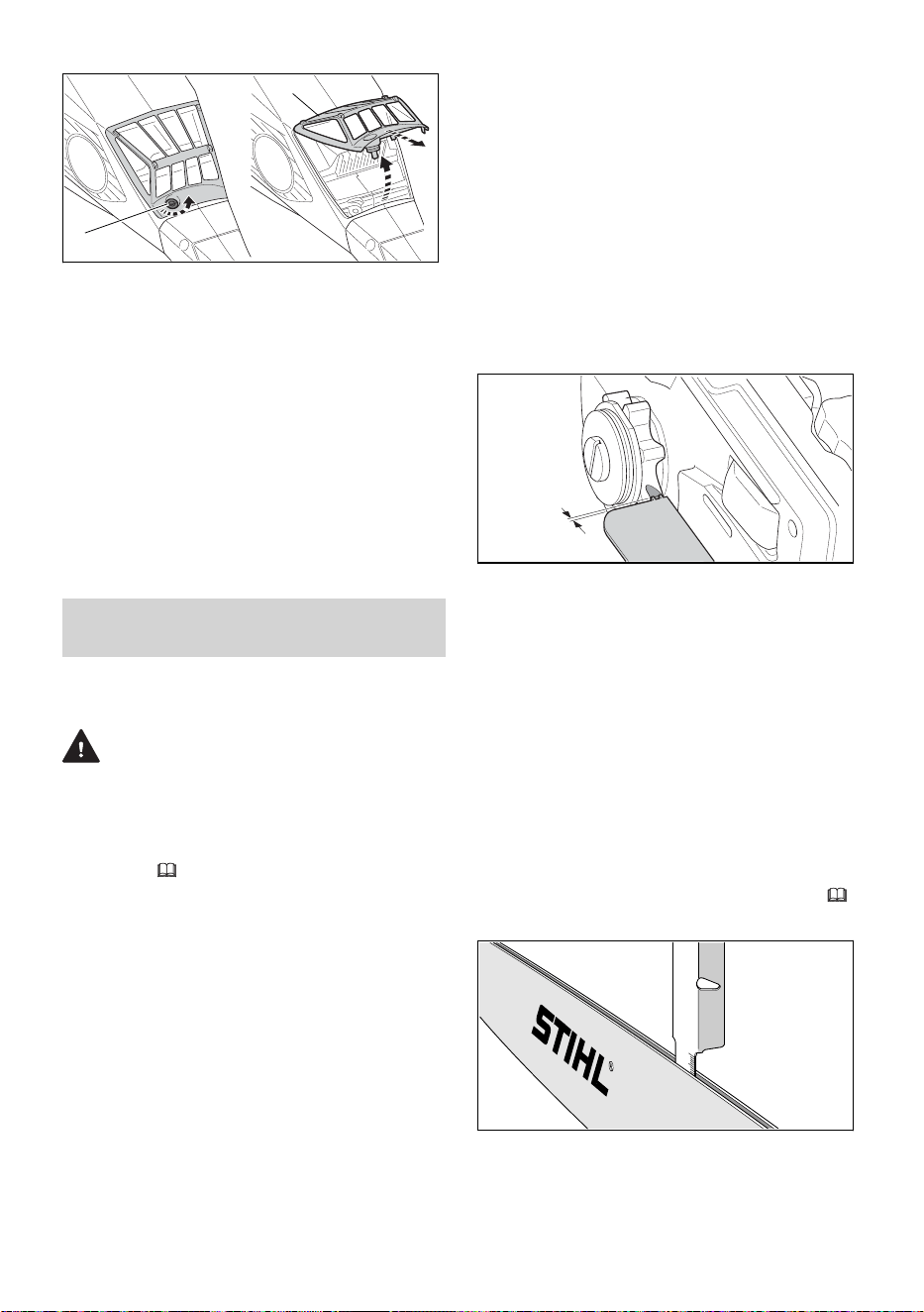
0000097125-001
1
2
► Limpie la zona alrededor del filtro de aire (2)
con un paño húmedo o con un cepillo suave.
► Gire el tornillo (1) en sentido antihorario hasta
que se pueda retirar el filtro de aire.
► Retire el filtro de aire levantándolo y tirando de
él.
► Retire las partículas de suciedad más gruesas
del exterior del filtro de aire con agua
corriente. Nunca limpie el filtro de aire con una
hidrolavadora.
► Si el filtro de aire está dañado, sustitúyalo.
► Espere a que el filtro de aire se seque.
► Una vez que el filtro de aire se haya secado
por completo, colóquelo en su lugar a mano.
► Apriete el tornillo.
24 Inspección y manteni‐
miento
24.1 Inspección y mantenimiento del
podador de varilla
ADVERTENCIA
■ Para reducir el riesgo de lesiones provocadas
por una activación accidental, retire la batería
antes de inspeccionar la podadora de pértiga
o de llevar a cabo cualquier trabajo de mante‐
nimiento,
9.
El mantenimiento adecuado de la podadora de
pértiga incluye las siguientes actividades:
► Limpiar el filtro de aire cada 50 horas de fun‐
cionamiento.
► Inspeccionar periódicamente el piñón de la
cadena y solicitar a un concesionario de servi‐
cio STIHL autorizado que lo reemplace si está
muy gastado.
► Inspeccionar la espada y comprobar si la
ranura tiene la profundidad y la anchura ade‐
cuadas; reemplazar la espada si presenta sig‐
nos de desgaste excesivo o daños.
► Afilar periódicamente la cadena, mantener las
guías de limitación de profundidad a la altura
apropiada y reemplazar la cadena de ase‐
rrado cuando las marcas de desgaste relevan‐
tes indiquen que es necesario, o cuando la
cadena esté dañada o muestre signos de des‐
gaste excesivo.
► Si las etiquetas de seguridad están gastadas,
dañadas, o faltan, solicite a un concesionario
de servicio STIHL autorizado que las reem‐
place.
24.2 Inspección y mantenimiento del
piñón de la cadena
► Apague el podador de varilla y quítele la bate‐
ría.
► Retire la cubierta del piñón, la cadena de ase‐
rrado y la espada.
a
0000097176_001
► Compruebe si la cubierta del piñón de la
cadena presenta marcas de desgaste.
► Si las marcas de desgaste tienen una profun‐
didad mayor que a = 0,020 in (0,5 mm), soli‐
cite que le cambien el piñón de la cadena.
STIHL recomienda el uso de piñones de cadena
originales de STIHL.
Alternar el uso de dos cadenas ayuda a reducir
el desgaste del piñón de la cadena.
24.3 Inspección y mantenimiento de
la espada
► Apague el podador de varilla y quítele la bate‐
ría.
►
Retire la espada y la cadena de aserrado,
15.6.2.
0000-GXX-1217-A0
► Mida la profundidad de la ranura de la espada
en la zona con mayor desgaste, usando la
herramienta de medición del calibre de limado
(accesorio especial, no incluido).
24 Inspección y mantenimiento español / EE.UU
0458-698-8621-B 77
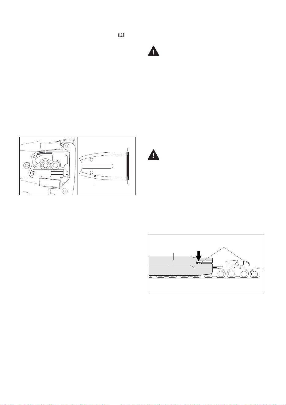
► Reemplace la espada si la profundidad
medida es inferior a las profundidades míni‐
mas requeridas que se especifican en 26.4.
► Mida la anchura de la ranura de la espada
usando la herramienta de medición del calibre
de limado.
► Cambie la espada si la ranura se ha estre‐
chado, se ha dilatado o presenta otros signos
de desgaste notable o daños.
Para mantener la espada:
► Dé vuelta a la espada después de cada afi‐
lado y cada vez que cambie la cadena. Esto
contribuye a evitar un desgaste desparejo. La
espada no tiene parte de "arriba" ni de
"abajo". Se puede usar colocada de cual‐
quiera de las dos maneras, aunque la rotula‐
ción puede quedar al revés.
3
1
2
3
0000097134_001
► Limpie el conducto de salida de aceite (1), el
orificio de entrada de aceite (2) y la ranura (3)
con un cepillo, con un paño ligeramente
húmedo o con un disolvente de resinas, como
el lubricante y eliminador de resinas STIHL.
No use detergentes.
► Retire periódicamente cualquier rebaba metá‐
lica que se acumule a lo largo de la espada
con una lima plana o con una herramienta rec‐
tificadora para la espada de STIHL.
► Cambie la espada si no puede limar las reba‐
bas o si la espada se daña.
24.4 Inspección, mantenimiento y
afilado de la cadena de ase‐
rrado
ADVERTENCIA
■ Una cadena mal afilada puede aumentar el
riesgo de que se produzca un contragolpe y
se liberen otras fuerzas reactivas que pueden
provocar lesiones graves o incluso la muerte.
Por ejemplo, los calibres de profundidad
demasiado bajos o los cortadores mal limados
pueden aumentar el riesgo de contragolpe del
podador de varilla, y pueden intensificar las
fuerzas del contragolpe y dificultar, por tanto,
el control del podador. Revise y siga siempre
las dimensiones y los ángulos de afilado reco‐
mendados por STIHL cuando revise o afile la
cadena.
ADVERTENCIA
■ No use nunca una cadena que esté roma o
dañada. Esto aumenta la fatiga física y la
carga que suponen las vibraciones, produce
resultados de corte no satisfactorios y un des‐
gaste más intenso. Si las virutas producidas
durante el corte son finas y más parecidas a
aserrín que a virutas de madera, es probable
que la cadena esté roma.
► Apague el podador de varilla y quítele la bate‐
ría.
1
0000-GXX-1218-A0
2
► Compruebe la altura del calibre de profundi‐
dad (1) con un calibre de limado STIHL (2)
adecuado para el paso de la cadena.
► Si el calibre de profundidad sobresale por
encima del calibre de limado, lime el calibre
de profundidad hasta que quede a la altura
adecuada.
► Trabaje con cuidado. Si lima demasiado los
calibres de profundidad, las fuerzas reactivas
aumentarán. Si los calibres de profundidad se
han limado demasiado, lleve la cadena a su
concesionario autorizado de STTIHL para que
la afilen o para que la cambien.
español / EE.UU 24 Inspección y mantenimiento
78 0458-698-8621-B
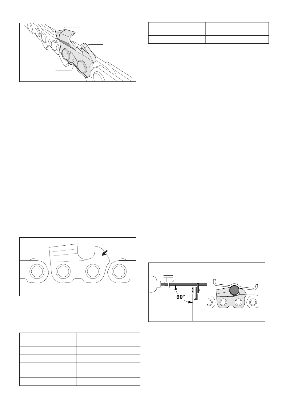
0000-GXX-1372-A0
1
2
3
4
La cadena de STIHL se ha fabricado con unas
marcas de desgaste pensadas para ayudar al
operador a saber cuándo el desgaste es exce‐
sivo. Las marcas de desgaste que se muestran
arriba (1 - 4) deben verse en todo momento.
► Cambie la cadena cuando cualquiera de estas
marcas ya no se vea.
► Revise el ángulo de afilado de 30° de los cor‐
tadores con un calibre de limado de STIHL
adecuado para el paso de la cadena.
► Si el ángulo de afilado es incorrecto, lime los
cortadores de modo que presenten un ángulo
de 30°.
► Si ve que no logra el ángulo adecuado o sos‐
pecha que no lo ha logrado, lleve la cadena a
afilar a un concesionario de servicio de STIHL
autorizado.
Una cadena mal limada puede ser muy peli‐
grosa. Puede aumentar la probabilidad de que
se liberen fuerzas reactivas, entre las que se
incluye el contragolpe, y aumentar además la
magnitud de estas fuerzas.
a
0000-GXX-1446-A0
La marca (a) de paso de la cadena está grabada
en la zona del calibre de profundidad de cada
cortador.
Las marcas significan lo siguiente:
Marca (a) Paso de la cadena de
aserrado
1 1/4"
2 0,325"
3 3/8"
4 0,404"
6 3/8" PICCO
Marca (a) Paso de la cadena de
aserrado
7 1/4" PICCO
Para afilar la cadena:
► Apague el podador de varilla y quítele la bate‐
ría.
► Seleccione una lima para cadena que tenga
un diámetro adecuado para el paso de la
cadena.
Otras limas no son adecuadas y pueden pro‐
vocar que la cadena no se lime correcta‐
mente, lo que, a su vez, puede aumentar la
probabilidad de que se produzca un contra‐
golpe o se liberen otras fuerzas reactivas, así
como la magnitud de dichas fuerzas.
► Si fuera preciso, fije la espada, para que el
limado le resulte más sencillo.
► Use un soporte de limas.
Los soportes de limas tienen una serie de
marcas que indican el ángulo de afilado ade‐
cuado.
► Lime todos los cortadores con el mismo
ángulo. Normalmente, dos o tres pasadas de
la lima son suficientes para un reafilado sim‐
ple. Retire un poco de material con cada
pasada.
Un afilado con alturas o ángulos distintos o no
homogéneos puede ser muy peligroso, y
puede hacer que la cadena gire de forma
brusca o irregular, que aumente el desgaste o
incluso que la cadena se rompa. También
puede aumentar la probabilidad de que se
produzca un contragolpe o se liberen otras
fuerzas reactivas, así como la magnitud de las
mismas.
0000-GXX-1219-A0
► Guíe la lima en horizontal a un ángulo
correcto con respecto a la superficie lateral de
la espada, de acuerdo con el ángulo especifi‐
cado.
► Lime siempre desde el interior del cortador al
exterior.
► Levante la lima en la pasada hacia atrás. La
lima solo afila en la pasada hacia delante.
24 Inspección y mantenimiento español / EE.UU
0458-698-8621-B 79
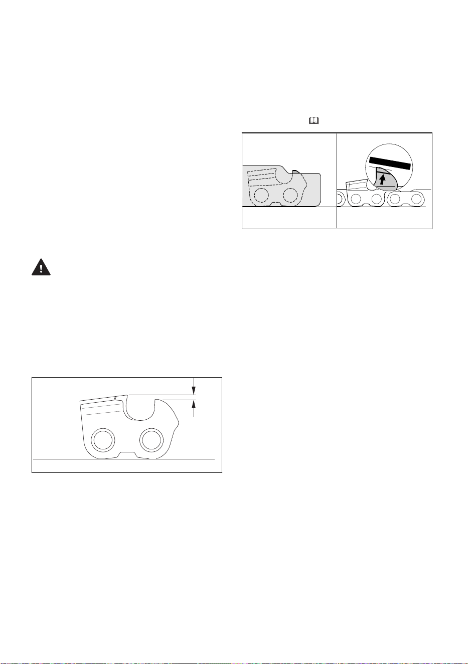
► No lime las correas de amarre ni los eslabo‐
nes impulsores.
► Rote la lima periódicamente para evitar un
desgaste desigual.
► Para retirar del diente cortador la rebaba de la
lima, pase el cortador por un trozo de madera
dura.
► Compruebe el ángulo de afilado con un calibre
de limado.
Todos los cortadores deben tener la misma lon‐
gitud, y afilarse hasta que lleguen a la longitud
del cortador más corto. Si no, aumentará la pro‐
babilidad de que se produzca un contragolpe o
de que se liberen otras fuerzas reactivas, así
como la magnitud de las mismas.
STIHL le recomienda que lleve su cadena a afi‐
lar a un concesionario de servicio STIHL autori‐
zado, para reducir el riesgo de que quede mal
afilada y produzca lesiones graves o incluso
mortales.
ADVERTENCIA
■ Los calibres de profundidad que estén dema‐
siado bajos aumentan la probabilidad de que
se produzca un contragolpe o se liberen otras
fuerzas reactivas, así como la fuerza de las
mismas. Esto, a su vez, puede incrementar el
riesgo de lesiones graves. Mantenga siempre
la distancia (a) adecuada entre el calibre de
profundidad y la parte superior del cortador.
a
0000-GXX-1447-A0
El calibre de profundidad determina la profundi‐
dad hasta la que el cortador penetra en la
madera y, por tanto, el grosor de las virutas.
Un calibre de profundidad que está demasiado
bajo aumentará el riesgo de que se produzca un
contragolpe del podador de varilla, y puede
intensificar las fuerzas del contragolpe.
Un calibre de profundidad que está demasiado
alto no permitirá que el cortador penetre en la
pieza de madera, y resultará en un rendimiento
de corte pobre. Mantenga siempre la distan‐
cia (a) necesaria entre el calibre de profundidad
y el filo cortante,
26.5.
0000-GXX-1220-A1
Para rebajar correctamente el calibre de profun‐
didad:
► Coloque en la cadena el calibre de limado
apropiado para el paso de la cadena y presió‐
nelo contra el cortador que quiere revisar. Si
el calibre de profundidad sobresale por
encima del calibre de limado, el calibre de pro‐
fundidad se debe rebajar con la lima.
► Lime el calibre de profundidad de modo que
quede alineado con la parte superior del cali‐
bre de limado.
► Después, retire el calibre de limado y lime el
borde delantero del calibre de profundidad en
paralelo a la marca de servicio. Cuando lo
haga, preste atención para no rebajar más el
punto más elevado del calibre de profundidad.
► Coloque el calibre de limado sobre la cadena
para comprobar la altura del calibre de limado.
El punto más alto del calibre de profundidad
debe quedar al ras de la parte superior del
calibre de limado.
► Tras el afilado, limpie meticulosamente la
cadena y retire cualquier resto de limado o de
lijado.
► Engrase bien la cadena.
español / EE.UU 24 Inspección y mantenimiento
80 0458-698-8621-B

25 Guía de solución de problemas
25.1 Podadora de pértiga y batería
Siempre retire la batería antes de realizar cualquier trabajo de inspección, limpieza o mantenimiento.
Problema LEDs de la
batería
Posible causa Solución
El podador de
varilla no arranca
cuando se
enciende.
No hay contacto
eléctrico entre el
podador de var‐
illa y la batería.
►
Retire la batería, 16.2.
► Inspeccione visualmente los contactos eléctri‐
cos del compartimento de la batería y de la
batería.
►
Vuelva a colocar la batería, 16.1.
1 LED des‐
tella en
verde.
Solo STIHL
AR: además,
se emiten
cuatro piti‐
dos largos.
La batería tiene
poca carga.
►
Cargue la batería, 11.
1 LED se ilu‐
mina en rojo.
La batería está
demasiado cal‐
iente/demasiado
fría.
► Espere a que la batería se caliente o se enfríe
gradualmente hasta alcanzar una temperatura
ambiente de entre 50 °F y 68 °F aproximada‐
mente (de 10 °C a 20 °C).
4 LED des‐
tellan en
rojo.
Solo STIHL
AR: además,
se emite una
sucesión
rápida de pit‐
idos cortos.
La batería no
funciona correc‐
tamente.
►
Retire la batería y colóquela de nuevo, 16.
►
Encienda el podador de varilla, 17.1.
► Si los LED siguen destellando, no intente usar
la máquina.
La batería no funciona correctamente, y es nec‐
esario cambiarla.
3 LED ilumi‐
nados en
rojo.
El podador de
varilla está
demasiado cal‐
iente.
► Espere a que el podador de varilla se enfríe.
3 LED des‐
tellan en
rojo.
El podador de
varilla está aver‐
iado.
►
Retire la batería y colóquela de nuevo, 16.
►
Encienda el podador de varilla, 17.1.
► Si los LED siguen destellando, no intente usar
la máquina.
El podador de varilla tiene una avería y debe
ser revisado en un concesionario de servicio.
El podador de
varilla se apaga
durante el funcio‐
namiento.
1 LED se ilu‐
mina en rojo.
La batería está
demasiado cal‐
iente/demasiado
fría.
►
Retire la batería, 16.2.
► Espere a que el podador de varilla y la batería
se enfríen gradualmente hasta alcanzar una
temperatura ambiente de entre 50 °F y 68 °F
aproximadamente (entre 10 °C y 20 °C).
3 LED ilumi‐
nados en
rojo.
El podador de
varilla está
demasiado cal‐
iente.
El tiempo de fun‐
cionamiento es
demasiado corto.
La batería no
está completa‐
mente cargada.
►
Cargue la batería, 11.
Se alcanzó o se
superó la vida
útil de la batería.
► Lleve la batería a un concesionario de servicio
STIHL autorizado para que la revisen.
Durante el ser‐
rado, la madera
despide humo o
La cadena está
roma o mal afi‐
lada.
►
Afile la cadena correctamente, 24.4.
25 Guía de solución de problemas español / EE.UU
0458-698-8621-B 81

Problema LEDs de la
batería
Posible causa Solución
huele a que‐
mado.
La técnica de
trabajo aplicada
no es adecuada,
o el podador de
varilla no se está
usando correcta‐
mente.
► Infórmese sobre las técnicas de trabajo adecua‐
das.
Falta aceite para
la espada y la
cadena.
► Encargue a un concesionario de servicio autori‐
zado de STIHL que revise el mecanismo de
lubricación de la cadena.
La batería no se
carga, aunque el
LED del carga‐
dor está encen‐
dido en verde.
1 LED se ilu‐
mina en rojo.
La batería está
demasiado cal‐
iente/demasiado
fría.
► Espere a que la batería se caliente o se enfríe
gradualmente hasta alcanzar una temperatura
ambiente de entre 50 °F y 68 °F aproximada‐
mente (de 10 °C a 20 °C).
► Lea y siga las advertencias e instrucciones en el
manual de su cargador. Para un rendimiento
óptimo, respete los rangos de temperatura
ambiente recomendados, 26.7.
La batería no se
puede localizar
con la aplicación
STIHL connec‐
ted.
La interfaz de
Bluetooth
®
no
está activada en
la batería o en el
dispositivo móvil.
►
Active la interfaz de Bluetooth
®
en la batería y
en su dispositivo móvil, 13.1..
La distancia
entre la batería y
su dispositivo
móvil es dema‐
siado grande.
► Reduzca la distancia entre la batería y su dispo‐
sitivo móvil, 26.2.
► Si aún así no puede localizar la batería con la
aplicación STIHL connected: póngase en con‐
tacto con un concesionario de servicio de STIHL
autorizado para pedir ayuda.
26 Especificaciones
26.1 STIHL HTA 135
–
Tipos de batería aprobados:
–
STIHL serie AP
–
Serie STIHL AR
–
Peso sin batería: 15,0 lb (6,8 kg)
–
Volumen máximo del tanque de aceite:
3.6 oz. (0,22 l)
Si necesita información técnica sobre las bate‐
rías de las series AR y AP de STIHL, consulte la
información de producto adjunta con su batería.
Si necesita información técnica sobre los carga‐
dores de las series AL 101, 301, 301-4 y 501 de
STIHL, consulte la información de producto
adjunta con su cargador.
Las baterías, los cargadores y otros accesorios
se venden por separado. Póngase en contacto
con su concesionario de servicio STIHL autori‐
zado para obtener información sobre precios y
disponibilidad.
26.2 Batería STIHL serie AP
Tipos de cargador aprobados: STIHL AL 101, AL
301, AL 301-4 o AL 501.
–
Tecnología de la batería: ion de litio
–
Voltaje: 36 V
–
Capacidad nominal en Ah
5
: Véase la placa de
características
–
Energía acumulada en Wh
6
: Véase la placa
de características
–
Peso en kg: Ver placa de características
5
Capacidad nominal calculada de acuerdo con CEI 61960. La energía útil disponible para el operador
será menor.
6
En la batería figura la energía acumulada de acuerdo con los datos facilitados por el fabricante de las
pilas. La energía útil disponible para el operador será menor.
español / EE.UU 26 Especificaciones
82 0458-698-8621-B

–
Interfaz de Bluetooth
®
(solo para baterías con
)
–
Protocolo de transmisión de datos: Blue‐
tooth
®
5.1. Los dispositivos móviles que
reciben los datos deben ser compatibles
con la versión Bluetooth
®
Low Energy 5.0 y
con el Generic Access Profile (GAP).
–
Banda de frecuencia: banda ISM 2.4 GHz
–
Potencia de transmisión máxima irradiada:
1 mW
–
Alcance de la señal Bluetooth
®
: como
máximo, 33 pies (10 m). El alcance de la
señal puede variar en función de las condi‐
ciones ambientales y del rendimiento del
dispositivo receptor, es decir, del teléfono
inteligente o la tableta. El alcance de Blue‐
tooth
®
puede verse limitado cuando la señal
se transmite a través de barreras metálicas
(por ejemplo: paredes, estanterías, etc.) o
en las cercanías de campos electromagnéti‐
cos fuertes.
–
Requisitos mínimos del sistema del disposi‐
tivo de terminal móvil (p. ej., tableta, telé‐
fono inteligente): Android o iOS (en versión
actual o superior)
Si quiere ver una lista completa de los tiempos
de carga aproximados, visite www.stihl.com/
charging-times.
Para obtener una lista completa de las horas de
funcionamiento aproximadas de la batería, visite
www.stihl.com/battery-life.
Bluetooth
®
La marca y logotipo de Bluetooth
®
son marcas
comerciales registradas, propiedad de Blue‐
tooth SIG, Inc. Estas marcas/logotipos son utili‐
zados por STIHL bajo licencia.
Si la batería está equipada con una interfaz
Bluetooth
®
se deben respetar las restricciones
de uso locales (en aviones o en hospitales, por
ejemplo).
Otras marcas comerciales
Apple y el logotipo de Apple son marcas comer‐
ciales de Apple Inc., registradas en EE.UU. y en
otros países.
App Store es una marca de servicio de Apple
Inc.
Google Play y el logotipo de Google Play son
marcas comerciales de Google Inc.
26.3 Piñones de cadena
Los piñones de cadena que figuran a continua‐
ción están disponibles para este modelo de
podador de varilla:
–
De 7 dientes para PICCO de 3/8" de paso
26.4 Profundidad de ranura mínima
de las espadas
La profundidad de ranura mínima de una espada
depende del paso de la misma.
–
Profundidad mínima de ranura para espadas
PICCO de 3/8" de paso: 0,197 in (5 mm)
26.5 Ajuste del calibrador de profun‐
didad
El ajuste del calibrador de profundidad de una
cadena de aserrado depende del paso de esta.
–
Ajuste del calibrador de profundidad para
cadenas PICCO de 3/8" in de paso: 0,026 in
(0,65 mm)
26.6 Límites de temperatura
ambiente
ADVERTENCIA
■ Las temperaturas extremas pueden dañar la
batería y provocar que esta genere calor, se
rompa, pierda líquido, se incendie o explote, lo
que podría causar lesiones personales graves
o fatales y daños materiales. Nunca cargue,
utilice o almacene la batería fuera de los lími‐
tes de temperatura ambiente especificados a
continuación.
–
No cargue la batería por debajo de - 4 °F (-
20 °C) ni por encima de 122 °F (50°C).
–
No utilice la podadora de pértiga ni la bate‐
ría por debajo de - 4 °F (- 20 °C) ni por
encima de 122 °F (50 °C).
–
No almacene la podadora de pértiga ni la
batería por debajo de - 4 °F (- 20 °C) ni por
encima de 158 °F (70 °C).
26.7 Recomendaciones de tempera‐
tura ambiente
Para un rendimiento óptimo, respete los siguien‐
tes rangos de temperatura ambiente para la
podadora de pértiga y la batería:
–
Carga: 41 °F a 104 °F (5 °C a 40 °C)
–
Uso: de 14 °F a 104 °F (de - 10 °C a 40 °C)
–
Almacenamiento: - 4 °F a 122 °F (- 20 °C a
50 °C)
26 Especificaciones español / EE.UU
0458-698-8621-B 83
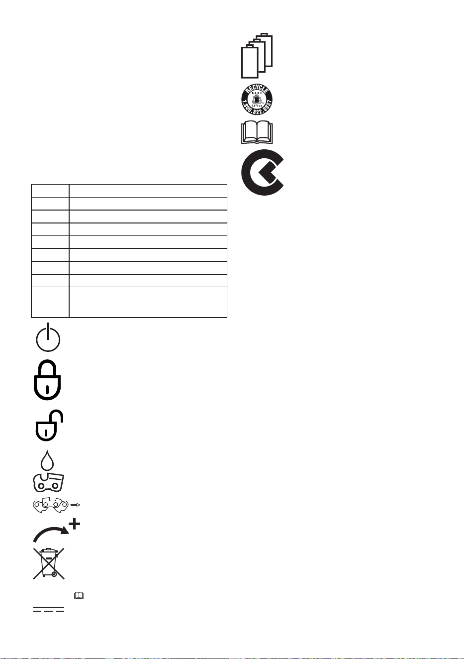
Cargar, utilizar o almacenar la batería fuera de
los rangos de temperatura ambiente recomenda‐
dos puede reducir su rendimiento.
Si la batería se mojó o humedeció durante el
funcionamiento, permita que se seque al menos
48 horas a temperaturas entre 59 °F (15 °C) y
122 °F (50 °C) y una humedad relativa por
debajo de 70 % antes de cargarla o guardarla.
Una humedad más alta puede prolongar el
tiempo de secado.
26.8 Símbolos en la podadora de
pértiga
Símbolo Significado
V Voltio
Hz Hertz
A Amperio
Ah Amperio-hora
W Vatio
Wh Vatio-hora
CA Corriente alterna
IPX4 Protección contra pulverización y salpi‐
caduras de agua desde todas las
direcciones.
Símbolo de encendido en el pestillo
de retención.
Encaje la tuerca de sujeción
Desencaje la tuerca de sujeción
Depósito de aceite de la cadena
Sentido de giro de la cadena de
sierra
Girar en sentido de las manecillas
del reloj para tensar la cadena de
sierra
Los productos STIHL no se deben
desechar junto con la basura domés‐
tica, sino de acuerdo con las leyes y
normas locales, estatales y federales
y como se especifica en este manual,
30.
Corriente continua
Número de pilas y energía acumulada
de acuerdo con las especificaciones
del fabricante de las pilas. La cantidad
de energía aprovechable será menor.
El sello RBRC indica que STIHL ha
pagado por adelantado por el reciclaje
de la batería.
Lea el manual
La batería está equipada con
Bluetooth
®
y se puede conectar
con la aplicación STIHL connec‐
ted.
26.9 Mejoramientos técnicos
STIHL tiene la filosofía de mejorar continua‐
mente todos sus productos. Como resultado de
ello, periódicamente se introducen cambios de
diseño y mejoras. Por lo tanto, es posible que
algunos cambios, modificaciones y mejoras no
se describan en este manual. Si las característi‐
cas de funcionamiento o la apariencia de su
máquina difieren de las descritas en este
manual, comuníquese con el concesionario
STIHL para obtener la ayuda que requiera.
26.10 Declaración de cumplimiento
de la norma FCC 15
Este dispositivo cumple con la parte 15 de las
normas de la FCC.
El funcionamiento está sujeto a las dos condicio‐
nes siguientes:
1)
Este dispositivo no puede causar interferen‐
cias dañinas y
2)
Este dispositivo debe aceptar cualquier inter‐
ferencia recibida, incluida aquella que pueda
provocar un funcionamiento no deseado.
Nota: Este equipo ha sido probado y se ha
determinado que cumple con los límites para un
dispositivo digital de Clase B, de conformidad
con la parte 15 de las Normas de la FCC. Estos
límites están diseñados para ofrecer protección
razonable contra las interferencias dañinas en
una instalación residencial. Este equipo genera,
utiliza y puede irradiar energía de radiofrecuen‐
cia y, si no se instala y utiliza de acuerdo con las
instrucciones, puede causar interferencias dañi‐
nas en las comunicaciones de radio. No obs‐
tante, no se ofrece garantía alguna de que la
interferencia no ocurrirá en una instalación parti‐
cular.
español / EE.UU 26 Especificaciones
84 0458-698-8621-B
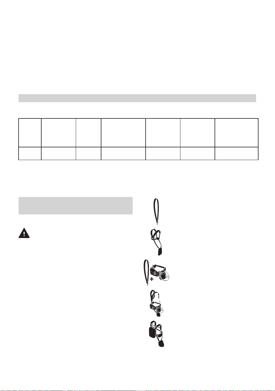
Si este equipo causa interferencias dañinas en
la recepción de radio o televisión, lo cual se
puede determinar encendiendo y apagando el
equipo, se recomienda al usuario que intente
corregir la interferencia mediante una o más de
las siguientes medidas:
–
Reorientar o reubicar la antena receptora.
–
Aumentar la separación entre el equipo y el
receptor.
–
Conectar el equipo a una toma de corriente de
un circuito diferente de aquel al que está
conectado el receptor.
–
Consultar a un concesionario de servicio auto‐
rizado de STIHL o a un técnico de radio/TV
con experiencia para recibir ayuda.
No cambie ni modifique este producto de nin‐
guna manera a menos que esté específicamente
permitido en este manual, ya que esto podría
anular su autoridad para operarlo.
27 Combinaciones de espadas y cadenas de aserrado
27.1 STIHL HTA 135
Paso Grueso del
eslabón
impulsor/
ancho de la
ranura
Largo Espada Número de
dientes del
piñón
Número de
eslabones
impulsores
Cadena de aser‐
rado
3/8" P
0,043 in
(1,1 mm)
10 in
(25 cm)
Rollomatic E /
Light 04
7 39
61 PMM3 (tipo
3610)
Las espadas mencionadas son espadas de contragolpe reducido con etiqueta verde de STIHL. Las
cadenas mencionadas son cadenas de bajo contragolpe con etiqueta verde de STIHL.
Puesto que existe la posibilidad de que se hayan desarrollado nuevas combinaciones de espada/
cadena tras la publicación de este manual, le recomendamos que pregunte en su concesionario
STIHL por las recomendaciones más recientes de STIHL.
28 Combinaciones de arnés
aprobadas
28.1 Combinaciones de arnés
ADVERTENCIA
■ El operador debe poder desenganchar el
arnés rápidamente en caso de emergencia.
Para reducir el riesgo de lesiones en caso de
emergencia:
–
Practique el proceso de desenganchar y
depositar la herramienta motorizada, como
haría en caso de emergencia. Para evitar
daños, no tire la herramienta motorizada al
suelo cuando esté practicando.
–
Utilice sólo una de las opciones de arnés
permitidas. No combine diferentes arneses
u otras combinaciones de arneses cuando
utilice su herramienta eléctrica.
Los siguientes arneses están disponibles para
su podadora de pértiga:
Correa para el hombro
Arnés completo
Cinturón para batería STIHL con
bolsa de batería de STIHL AP con
cordón de conexión en combina‐
ción con la correa para el hombro
Cinturón para batería STIHL con
bolsa de batería de STIHL AP con
cordón de conexión en combina‐
ción con arnés para el hombro y
almohadilla para la cadera
Batería tipo mochila STIHL AR en
combinación con almohadilla para
la cadera
27 Combinaciones de espadas y cadenas de aserrado español / EE.UU
0458-698-8621-B 85
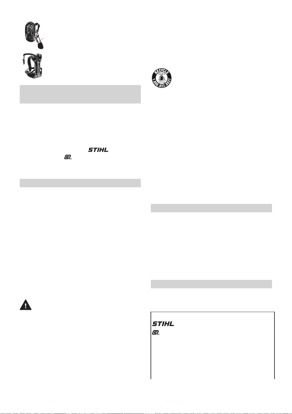
Batería tipo mochila STIHL en
combinación con almohadilla para
la cadera
Arnés RTS
29 Piezas y equipos de
repuesto
29.1 Piezas de repuesto originales
de STIHL
STIHL recomienda el uso de piezas de repuesto
originales de STIHL. Es posible identificar las
piezas originales de STIHL por el número de
pieza STIHL, el logotipo de
y, en ciertos
casos, el símbolo
de piezas STIHL. En las
piezas pequeñas el símbolo puede aparecer
solo.
30 Eliminación
30.1 Desecho de la herramienta
motorizada
Los productos STIHL no se deben desechar
junto con la basura del hogar, sino de la manera
en que se detalla en este manual.
► Tome la herramienta motorizada y su emba‐
laje a un sitio aprobado para desecharla y que
efectúe un reciclaje no dañino al medio
ambiente.
► Comuníquese con un concesionario de servi‐
cio STIHL
autorizado para obtener la informa‐
ción más actualizada sobre eliminación y reci‐
clado.
30.2 Reciclado de las baterías
ADVERTENCIA
■ Manipule las baterías descargadas/agotadas
con cuidado. Aunque parezca que están des‐
cargadas, las baterías de ion de litio nunca se
descargan completamente y pueden generar
una corriente de cortocircuito peligrosa. Si se
dañan o exponen a temperaturas extremas,
pueden perder líquido, generar calor, incen‐
diarse o explotar.
► Respete todas las leyes y normas federales,
estatales y locales sobre eliminación de dese‐
chos.
► Comuníquese con un concesionario de servi‐
cio STIHL autorizado para obtener la informa‐
ción más actualizada acerca de la eliminación
de desechos.
► Recicle las baterías agotadas rápidamente.
► Mantenga las baterías alejadas de los niños.
No desarme el producto ni lo incinere.
STIHL está comprometida con el
desarrollo de productos que protejan
el medio ambiente. Este compromiso
no termina cuando el producto sale
del concesionario de servicio STIHL
autorizado. STIHL se asoció con la
RBRC (Corporación de Reciclaje de
Baterías Recargables) para fomentar
la recolección y el reciclado de bate‐
rías de ion de litio STIHL en los Esta‐
dos Unidos y Canadá.
El sello de la RBRC indica que STIHL ya aportó
dinero para el reciclado de la batería. El sello de
la RBRC lleva impreso un número telefónico gra‐
tuito (1-800-822-8837) que le permite acceder a
información sobre lugares de reciclaje de bate‐
rías y prohibiciones o restricciones respecto del
reciclado de baterías en su zona. También
puede devolver las baterías a cualquier conce‐
sionario de servicio STIHL autorizado para reci‐
clarlas gratuitamente.
31 Garantía limitada
31.1 Política de garantía limitada de
STIHL Incorporated
Este producto se vende sujeto a la Política de
garantía limitada de STIHL Incorporated, dispo‐
nible en www.stihlusa.com/warranty.html. Tam‐
bién puede obtenerlo de un concesionario de
servicio STIHL autorizado o llamando al 1-800-
GO-STIHL (1-800-467-8445).
32 Marcas comerciales
32.1 Marcas comerciales registra‐
das
STIHL
®
FARM BOSS
®
iCademy
®
MAGNUM
®
STIHL Cutquik
®
MasterWrench Service
®
ROCK BOSS
®
MotoMix
®
KISS MY AXE
®
OILOMATIC
®
AutoCut
®
STIHL DUROMATIC
®
YARD BOSS
®
STIHL Quickstop
®
español / EE.UU 29 Piezas y equipos de repuesto
86 0458-698-8621-B

STIHL ROLLOMA‐
TIC
®
STIHL WOOD BOSS
®
WOOD BOSS
®
TIMBERSPORTS
®
DIRT BOSS
®
iMOW
®
La combinación de colo‐
res naranja-gris (registros
de EE. UU. 2,821,860;
3,010,057; 3,010,058;
3,400,477 y 3,400,476)
32.2 Marcas comerciales por ley
común
4-MIX™ STIHL Injection™
BioPlus™ STIHL PowerSweep™
Easy2Start™ Team STIHL™
EasySpool™ HEXA™
ElastoStart™ IntelliCarb™
Ematic™ Master Control Lever™
STIHL Precision
Series™
Stihl Outfitters™
FixCut™ STIHL PICCO™
Micro™ TrimCut™
Pro Mark™ STIHL M-Tronic™
TapAction™ On A Single Charge™
Quiet Line™ STIHL PolyCut™
STIHL Moto4™ STIHL RAPID™
STIHL SuperCut™
Esta lista de marcas comerciales está sujeta a
cambios.
Queda terminantemente prohibido todo uso de
estas marcas comerciales sin el consentimiento
expreso por escrito de
ANDREAS STIHL AG & Co. KG, Waiblingen.
33 Direcciones
33.1 STIHL Incorporated
STIHL Incorporated
536 Viking Drive
P.O. Box 2015
Virginia Beach, VA
23452-2015
33 Direcciones español / EE.UU
0458-698-8621-B 87

www.stihlusa.com
*04586988621B*
*04586988621B*
0458-698-8621-B
0458-698-8621-B
Estos podador de varilla y esta bateria
contienen productos químicos considerados
por el Estado de California como causantes
de cáncer, defectos de nacimiento u otra
toxicidad reproductora.
ADVERTENCIA
This pole pruner and battery contain
chemicals known to the State of California
to cause cancer, birth defects or other
reproductive harm.
WARNING