
240-2093
SAVE THIS MANUAL
You will need this manual for safety instructions, operating procedures and warranty.
Put it and the original sales receipt in a safe dry place for future reference.
For questions about this product, Please call 1-866-915-8626
Operator’s Manual
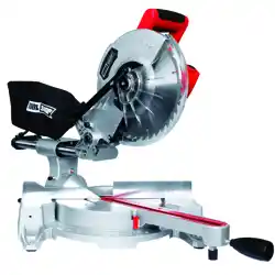
10 " 15 AMP SLIDING COMPOUND MITER SAW
2
IMPORTANT SAFETY INSTRUCTIONS
WARNING: When using electric tools, machines or equipment, basic safety
shock, and personal injury.
READ ALL INSTRUCTIONS BEFORE USING THIS TOOL
1. KEEP WORK AREA CLEAN. Cluttered areas can cause injuries.
2. CONSIDER WORK AREA ENVIRONMENT. Don’t use power tools in damp,
wet, or poorly lit locations. Don’t expose tools to the rain. Keep the work area
3. KEEP CHILDREN AND BYSTANDERS AWAY.
away from the work area. Don’t let them handle machines, tools or extension
cords.
4.
5. OBSERVE PROPER PRECAUTIONS REGARDING DOUBLE INSULA-
TION.
6. GUARD AGAINST ELECTRIC SHOCK.
electric shock if you contact a live wire.
7. DO NOT MISUSE THE CORD.
2
immediately.
8. WHEN WORKING OUTDOORS, USE AN OUTDOOR-RATED EXTENSION
CORD.
9. DO NOT EXPOSE ELECTRICAL POWER TOOLS TO MOISTURE.
wet conditions can cause water to enter the tool and lead to electric shock.
10. ENSURE THE EXTENSION CORD YOU USE IS OF SUFFICIENT GAUGE
FOR ITS LENGTH.
11. STORE IDLE EQUIPMENT.
reach of children.
12. DON’T FORCE THE TOOL. It
rate for which it was intended.
13. USE THE RIGHT TOOL. Don’t force a small tool or attachment to do the
not intended.
14. DRESS PROPERLY.
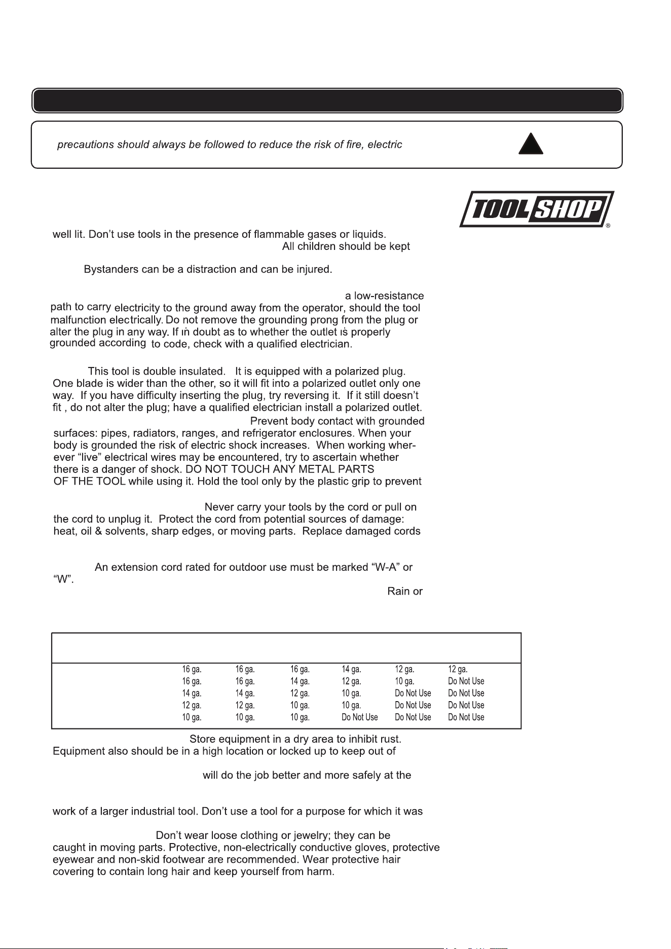
Recommended Minimum Wire Gauge for Extension Cords
Amps
from
Tool Nameplate
25’ length 50’ length 75’ length 100’ length 150’ length 200’ length
0-5 amps
5.1-8 amps
8.1-12 amps
12.1-15 amps
15.1-20 amps
!
GROUNDED TOOLS MUST BE PLUGGED INTO AN OUTLET THAT IS
PROPERLY INSTALLED AND GROUNDED.
This provides
3
IMPORTANT SAFETY INSTRUCTIONS
SAFETY PRECAUTIONS FOR COMPOUND MITER SAW
15. USE EYE PROTECTION.
or coarse dust.
16. SECURE WORK.
17. DON’T OVERREACH.
18. MAINTAIN TOOLS.
19. AVOID UNINTENTIONAL STARTING. Be sure the switch is in the OFF posi
21. DO NOT USE THE TOOL IF IT CANNOT BE SWITCHED ON OR OFF.
22. DISCONNECT THE PLUG FROM THE POWER SOURCE BEFORE MAKING
ANY ADJUSTMENTS.
if the tool would accidentally start.
23. STAY ALERT.
any tool when you are tired.
24. CHECK FOR DAMAGED PARTS.
center. Don’t use the tool if switch does not turn it on and off properly.
25. REPLACEMENT PARTS.
parts.
26. SERVICE AND REPAIRS
shock or injury.
1.
2.
WOOD ONLY.
3.
DAMAGED OR WARPED SAW BLADES SHOULD NOT BE USED.
injury.
4.
USE ONLY WITH GUARD IN PLACE.
in use.
5.
REPLACE THE TABLE INSERT WHEN WORN.
part of your saw.
6.
7.
CONNECT YOUR MITER SAW TO A DUST COLLECTING DEVICE IF POSSIBLE.
USE A SAWBLADE SUITED TO THE CUTTING JOB AND MATERIAL TO BE
CUT.
20. ALWAYS CHECK AND MAKE SURE TO REMOVE ANY ADJUSTING KEYS OR
WRENCHES BEFORE TURNING THE TOOL ON.
ALWAYS USE THE BLADE WRENCH TO TIGHTEN THE SAW BLADE ONTO
THE ARBOR.
damage
SPECIFICATIONS
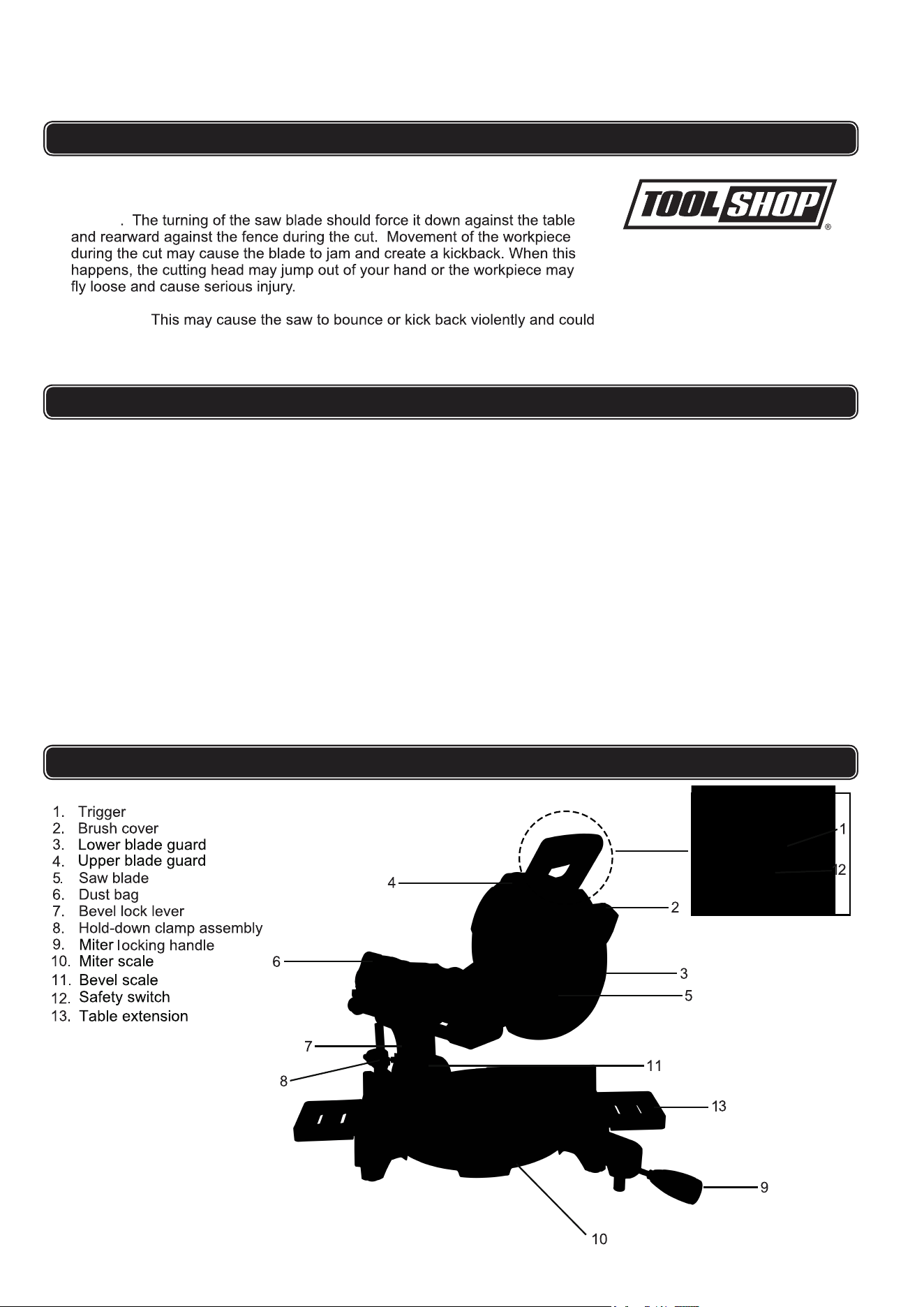
FUNCTIONAL DESCRIPTION
SAFETY PRECAUTIONS FOR COMPOUND MITER SAW
8.
9. THE MATERIAL SHOULD BE PLACED FIRMLY AGAINST THE FENCE AND
TABLE
10. DO NOT START THE SAW WITH THE BLADE IN CONTACT WITH ANY
SURFACE.
cause injury.
11.
Contents:Miter Saw,(1)10" Carbide Tipped Blade, Blade Wrench, (1) Hold-Down Clamp,
Dust Collection Bag & Product Manual, (2) Table Extensions.
Voltage: 120 volts AC, 60Hz
Current rating: 15 Amps
Blade Speed: 5000 RPM(No-Load Speed)
Blade Diameter: 10"
Arbor Size: 5/8"
Positive Miter Stops: 0, 15, 30 & 45 degree
Miter Angle: 45 degree Left/ 45 degree Right
Bevel cuts up to 45 degree Left
Power Cord: 6 ft
Weight: 27.5 lbs
Cutting Capacity: 90 degree Cross cut 2-7/8" x 11-7/8"
45 degree Miter Cut 2-7/8" x 7-7/8"
45 degree Bevel Cut 1-5/8" x 11-7/8"
45 degree Miter/Bevel Cut 1-5/8" x 7-7/8"
ALWAYS USE TABLE EXTENSIONS AND CLAMPS TO SUPPORT THE MATERIAL
WHEN SAWING LONG WORK PIECES.
IF MAKING A CUT USING ONE HAND TO HOLD THE SAW,ENSURE THE FREE
HAND IS CLEAR OF CUTTING AREA.
4
OPERATING PROCEDURES
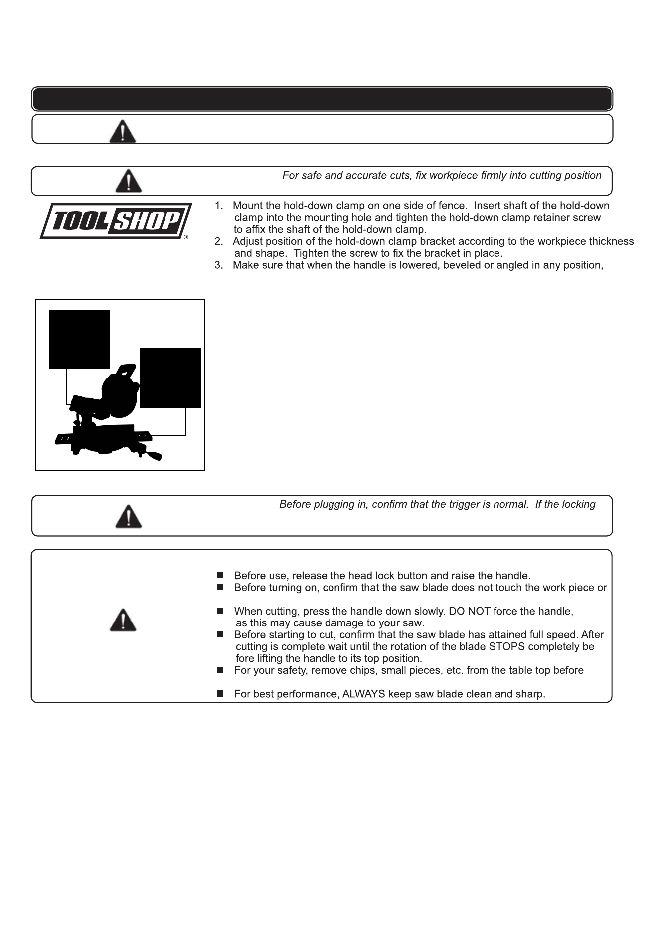
CLAMPING WORKPIECE:
WARNING:
.degamad eb yam eceipkrow dna loot eht esiwrehto ,pmalc nwod -dloh htiw
no part of the tool contacts the hold-down clamp.
START UP
USING YOUR SAW
After unpacking, reading the instructions, attaching the machine to the workbench,
and checking that all attachments are correctly installed, you can use your saw.
Be sure to wear the appropriate protective equipment.
1. Check to ensure everything is correctly attached, screws are fastened, and all
adjusting keys and wrenches are removed.
2. Put on the dust bag(#6 on page 4) and install the table extension(#13 on page 4)
with the screw provided.
3. Connect the saw to power.
4. Unlock the saw from its various storage and shipping positions.
5. Push forward the safety switch.(#12 on page 4). Pressing the trigger(#1 on page 4)
switclh will start the saw.
CAUTION! Be sure the saw is disconnected from its power source before making
any repairs or performing maintenance!
WARNING:
button is not depressed, do not pull the trigger with force as this may cause severe
damage to the switch.
REMEMBER:
the vise at any position.
-
operation.
5
-
cally.
-
cally.
MODES OF USE
Chop cut:
Miter cut:
to
Bevel cut:
Compound cut:
NOTE:
side of the table to prevent interfering with the movement of the cutting head.
Always check before making the cut if there is any potential interference from the
clamp or any other part of the machine.
OPERATING PROCEDURES
MAINTENANCE
NOTE: Even though the angles are marked on the machine, it is always a good
idea to check them by making a trial cut. See Aligning Miter and Bevel
on next page.
-
soap and a damp (not wet) cloth.
lower blade
6
ALIGNING MITER AND BEVEL
Miter Angle
-
-
Bevel Angle
A. Vertical stop: 0 degree adjustment
MAINTENANCE
the screws and adjust the needle.
B. Bevel stop: 45 degrees adjustment
screws and adjust the needle.
Bevel Scale
Make sure the Fence is perpendicular (at a 90° angle) to the Saw Blade,using
carpenter square (can be purchased at any hardware store, and comes in
various sizes.).
, using a small
, using a small
carpenter square;
carpenter square;
carpenter square
7
MAINTENANCE
REPLACING SAW BLADE
1
FIG.1
FIG.2
1.When replacing the saw blade, make
sure the new saw blade has a diameter of
10”, an RPM rating of at least 6,000, and an
arbor hole of 5/8” diameter.
3.Put the saw in the upper position.
2.When mounting the new saw blade,
the direction arrows on the blade should
correspond with the arrow on the upper
guard.
A. Upper blade guard
B. Lower blade guard
C. Saw teeth
pointing down
(See Figure.1)
(See Figure. 2)
FIG.2
FIG.3
4.Loosen screws that hold lower guard
in place so that guard can be rotated
(note screws do not need to be removed).
Use #3 Phillips head screwdriver for screw
D and 1/4” hex key for screw E (See Figure.3).
MAINTENANCE
A
B
C
D
E
FIG.1
8

MAINTENANCE
SPINDLE BOLT
CLOCKWISE
TO LOOSEN
7.Use the wrench to unscrew and remove the spindle bolt.NOTE: The Spindle
Bolt unscrews in a clockwise direction.Then,remove the Outer Flange. (See
Figure 6.)
8.INSTALL A NEW BLADE
Make sure to match the direction arrows marked on the new blade with the
direction arrows marked on the upper blade guard (saw teeth should always be
pointing downward).
Replace outer flange.
Tighten spindle bolt securely,using the blade wrench and tightening
counterclockwise.
Rotate lower blade guard back into place,replace any screws that were removed,
tighten the screws that hold the upper and lower guard in place,by tightening in
clockwise rotation.
Remove cross pin so the saw can be lowered into cutting position.
Disengage spindle lock.
5.Rotate the lower blade guard (B) out of the way. (see Figure 4.)
FIG.5
FIG.5
6.Depress the spindle lock (F) to keep the saw blade from turning.(See Figure 5.)
FIG.6
B
F
9
FIG.4
FIG.5
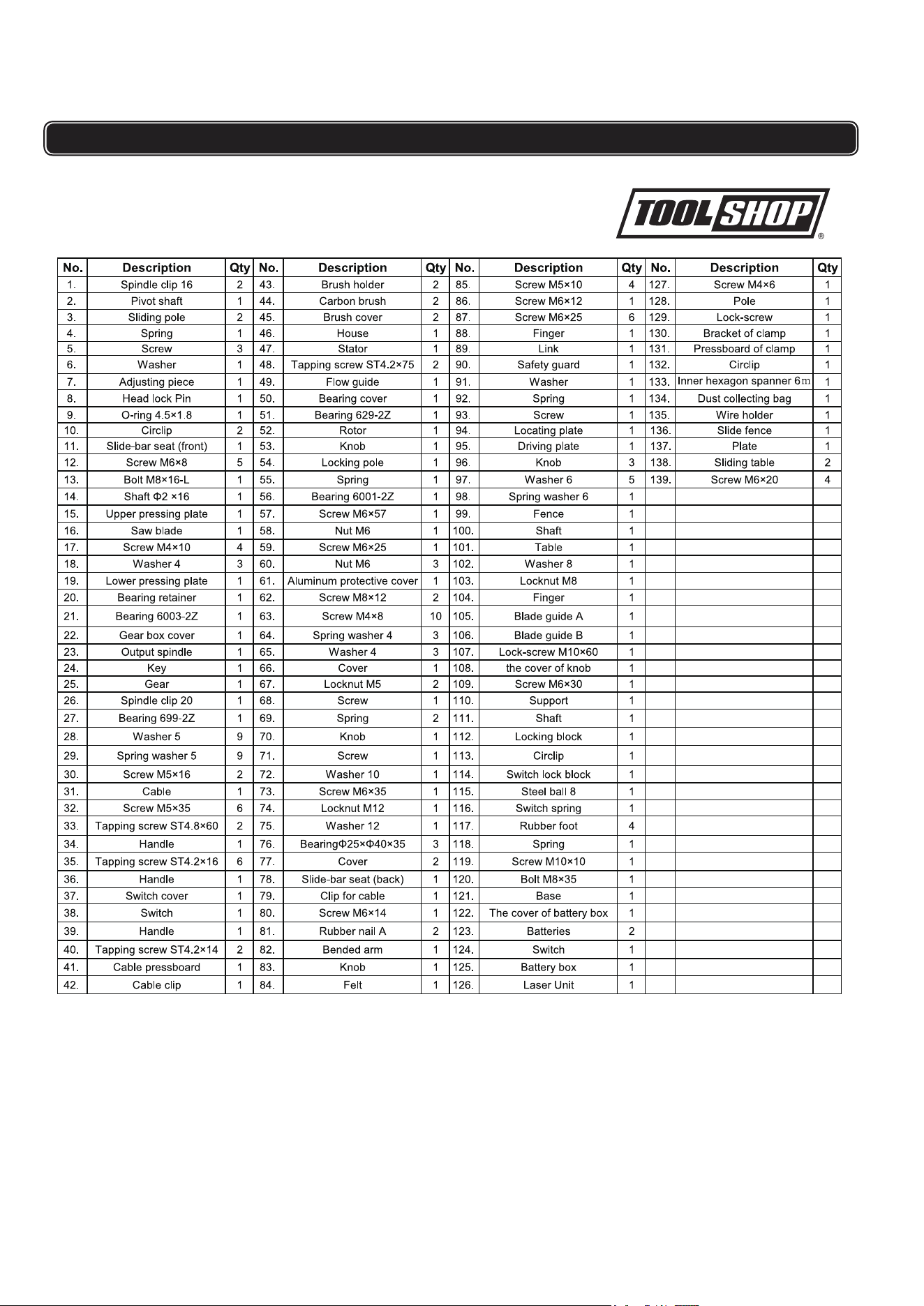
Please refer to the schematic drawing on page 11.
PARTS LIST
10
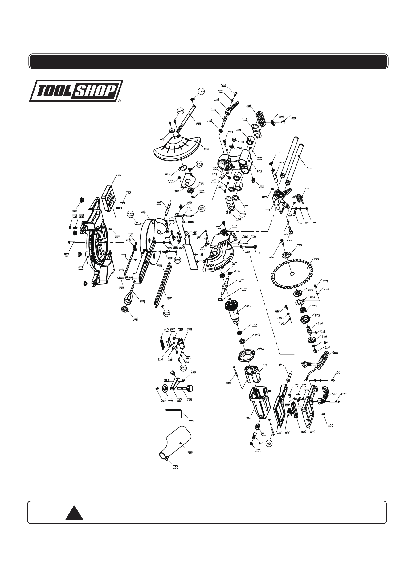
SCHEMATIC DRAWING
!
WARNING Repairs should be made by an authorized repair center. Do not
this power tool
. Contact at
for questions regarding this power tool.
1-866-915-8626
open or disassemble
11

TOOL SHOP®
1-YEAR LIMITED WARRANTY:
This
TOOL SHOP®
brand power tool carries a 1-Year Limited Warranty to the
original purchaser.
If the tool fails within one (1) year from the date of
purchase, simply bring this tool with your original sales receipt back to your
nearest
MENARDS
®
retail store. At its discretion,
TOOL SHOP®
agrees to
have the tool replaced with the same or similar
TOOL SHOP®
product free of
charge, within the stated warranty period, when returned by the original
purchaser with original sales receipt. Notwithstanding the foregoing, this
limited warranty does not cover any damage that has resulted from abuse or
misuse of the Merchandise. This warranty: (1) excludes expendable parts
including but not limited to blades, belts, bits, light bulbs, and/or batteries; (2)
shall be void if this tool is used for commercial and/or rental purposes; and (3)
does not cover any losses, injuries to persons/property or costs. This
warranty does give you specific legal rights and you may have other rights,
which vary from state to state. Be careful, tools are dangerous if improperly
used or maintained. Seller’s employees are not qualified to advise you on the
use of this Merchandise. Any oral representation(s) made will not be binding
on seller or its employees. The righ
ts under this limited warranty are to the
original purchaser of the Merchandise and may not be transferred to any
subsequent owner. This limited warranty is in lieu of all warranties,
expressed or implied including warranties or merchantability and fitness for a
particular purpose. Seller shall not be liable for any special, incidental, or
consequential damages. The sole exclusive remedy against the seller will be
for the replacement of any defects
as provided herein, as long as the seller is
willing or able to replace this product or is willing to refund the purchase price
as provided above.
For insurance purposes, seller is not allowed to
demonstrate any of these power tools for you.
For questions / comments, technical assistance or repair parts –
Please call toll free at: 1-866-915-8626
(M-F 8am – 5pm EST)
SAVE YOUR RECEIPTS.
THIS WARRANTY IS VOID WITHOUT THEM.
10" 15 AMP SLIDING MITER SAW WARRANTY
12