CO
2
CONTROLLER
ENVIRONMENTAL MONITOR
USER MANUAL


3
WELCOME
Thank you for choosing AC Infinity. We are committed to product quality and friendly customer service.
If you have any questions or suggestions, please don’t hesitate to contact us. Visit www.acinfinity.com
and click contact for our contact information.
EMAIL
support@acinfinity.com
WEB
www.acinfinity.com
LOCATION
Los Angeles, CA

4
PRODUCT
CO
2
CONTROLLER
MODEL
AC-CTC7
UPC-A
819137022997
MANUAL CODE CTC2210X1

5
MANUAL INDEX
Manual Index .................................................................................
Product Warning ............................................................................
Key Features .................................................................................
Product Contents ...........................................................................
Powering and Setup........................................................................
Programming .................................................................................
Other Settings ................................................................................
Other AC Infinity Products .............................................................
Warranty ........................................................................................
Page 5
Page 6
Page 7
Page 8
Page 9
Page 12
Page 25
Page 26
Page 27

6
Ensure your power source conforms to the electrical requirements of this product.
Check your local code restrictions for additional safety measures that may be needed for a
proper code compliant installation.
Read all instructions before installing and using this product.
When cutting or drilling into a wall or ceiling, do not damage electrical wiring and other
hidden utilities.
If you are unfamiliar or have doubts about performing this product’s installation, seek the
services of a qualified, trained, and licensed professional. Inappropriate installation will void
this product’s warranty.
This product must not be used in potentially hazardous locations such as flammable,
explosive, chemical-laden or wet atmospheres.
Do not cover power cords with rugs or other fabric materials.
Do not depend on the on/off programming as the sole means of shutting power from this
product. Unplug the power cord before installing, servicing, or moving this product.
Do not operate this product while its cord is damaged, or if it malfunctions, has been dropped,
or is damaged in any manner.
Use this product only as intended by the manufacturer.
1.
2.
3.
4.
5.
6.
7.
8.
9.
10.
PRODUCT WARNING
TO REDUCE THE RISK OF FIRE, ELECTRIC SHOCK, OR INJURY TO PERSONS,
OBSERVE THE FOLLOWING:
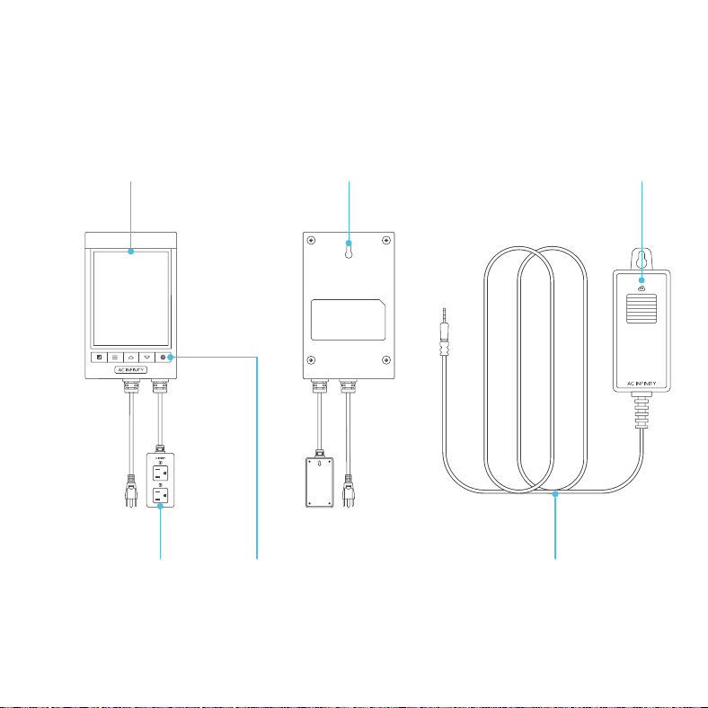
7
KEY FEATURES
ACTIVE MONITORING
LED display shows key data
like outlet power status, CO
2
trends, clock, and cycle.
WALL MOUNTING
Hard black housing and
fire-resistant casing with key-
hole hanger for easy mounting.
SMART CONTROLLER
Features automation controls
that power and activate your
outlet devices featuring CO
2
,
fan, and cycle programming.
DUAL OUTLETS
Built with a detached electrical
socket module that allows for
powering and controlling two
individual devices.
CUTTING EDGE SENSOR
Next-generation sensor using
photoacoustic technology to
accurately read CO
2
levels.
EXTRA CORD LENGTH
Extended cord length of 144
inches (12 feet) for ease of
management and flexible
mounting options.
8
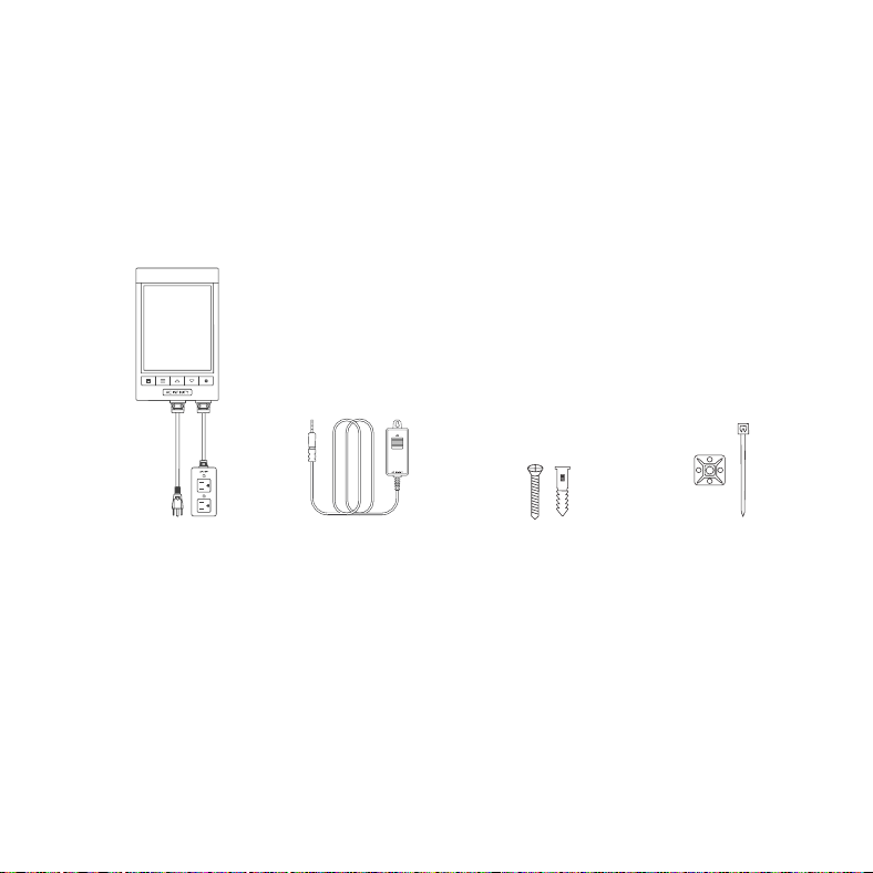
PRODUCT CONTENTS
WALL-HANG
WOOD SCREWS
(x3)
WIRE
MOUNT
(x1)
CO
2
CONTROLLER
(x1)
CO
2
SENSOR
(x1)
9
POWERING AND SETUP
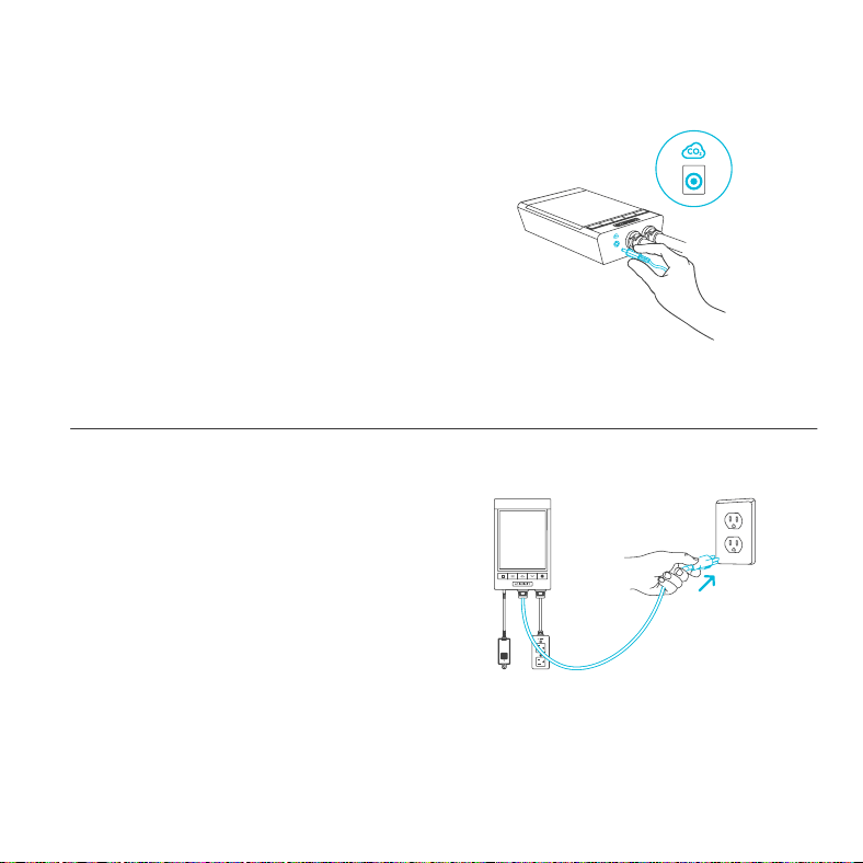
STEP 2
Insert the power plug into a wall outlet to power
your controller.
STEP 1
Plug the sensor probe into the 3.5mm port
located at the bottom side of your controller.
10
POWERING AND SETUP
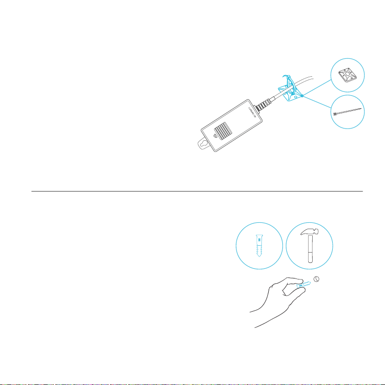
STEP 4
Locate a spot free of obstruction and secure the
anchor into your wall. Twist the wood screw into
the anchor.
STEP 3
Secure the corded sensor using the included
wire tie and adhesive mount.
You may also wall hang the corded sensor. Refer
to the next steps for wall hanging instructions.
11
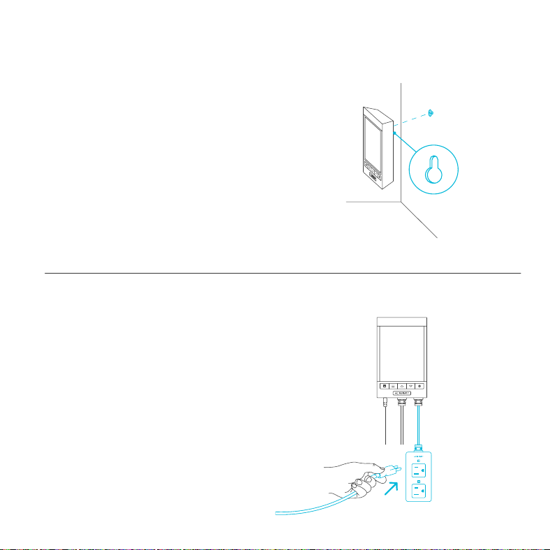
STEP 5
Hang your controller by the screw using the
hole located on its backside.
POWERING AND SETUP
STEP 6
Plug your fan and/or CO
2
generator (not included)
into the sockets to power it with your controller.
12
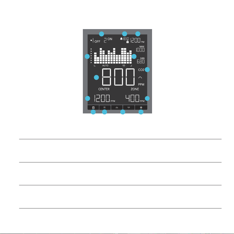
1. OUTLET BUTTON
Switches between Outlet 1 and Outlet 2. Set programs will still be active regardless of your
current outlet.
PROGRAMMING
2. MODE BUTTON
Cycles through each of the controller’s modes: OFF, ON, CO
2
(Center and Zone), Fan (Center and
Zone), and CYCLE (On and Off).
4. SETTING BUTTON
Cycles through each of the controller’s settings: CO
2
CHART, NIGHT1 (Start and End), NIGHT 2
(Start and End), ALARM HIGH, ALARM LOW, DISPLAY BRIGHTNESS, CLOCK, CALIBRATION.
3. UP/DOWN BUTTONS
Adjusts the value of your current mode. The up button increases and down button decreases the
setting. Hold both to reset values to factory settings.
1 2 3 4
5 6
7
10
11
8
12 13
9
5. OUTLET STATUS
Displays the devices’ active status, ON or OFF, indicating whether or not power is being fed.

13
6. STATUS ICONS
Flashes or displays the alert icons of the controller. The icons include ALARM, TIMER ALERT, and
DISPLAY LOCK.
7. CURRENT TIME
Displays the current time. The internal battery sustains the clock so it does not default to 00:00 if
power is cut off. See page 22 to learn how to set the clock time.
PROGRAMMING
8. CO
2
CHART
Displays CO
2
levels over a set period, adjustable in controller settings (see page 19). Also displays
minimum and maximum PPM levels based on the current time scale.
9. TARGET ZONE ARROWS
Indicates whether the current CO
2
reading is within range of your center and zone programming.
10. SENSOR READING
Displays current CO
2
levels measured within a 0-5000ppm range. Changes in 1ppm units when
under 1000ppm, 5ppm units when in between 1000-2000ppm, and 10ppm units when over
2000ppm. Trend indicator signals a rise, steady, or fall in CO
2
levels within the last hour.
11. CURRENT MODE
Displays the current mode, CO
2
or FAN, indicating which mode your outlet is in.
12. CENTER SET POINT / COUNTDOWN
Displays the countdown of the TIMER TO ON, TIMER TO OFF, CYCLE, or SCHEDULE modes. TO
ON shows the amount of time left before your devices power on. TO OFF shows the amount of time
left before your devices power off.
13. ZONE VALUE / USER SETTING
Displays the value of your current mode. Use the up and down buttons to adjust the value.
14
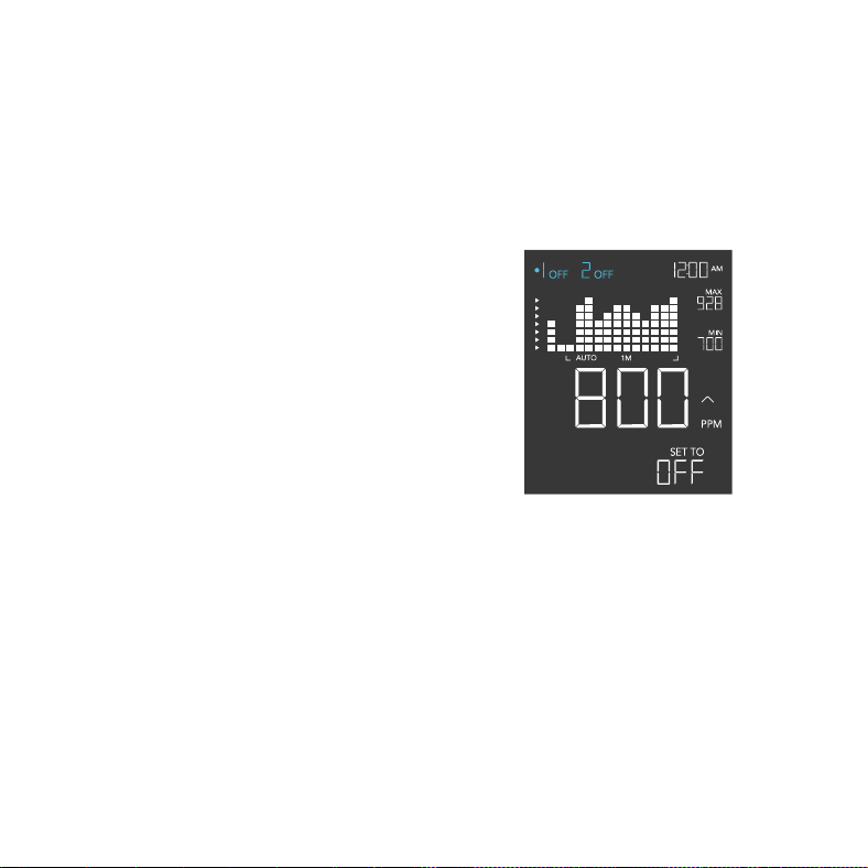
OUTLET TOGGLING
Pressing the outlet button switches between the controller’s two devices: Outlet 1 and Outlet 2. The
dot indicates the controller’s current device.
OUTLET 1 & OUTLET 2
Navigate to a numbered outlet with a device
plugged in to set individual programming.
Programs will run in the background even while
you navigate to the other outlet.
PROGRAMMING
15
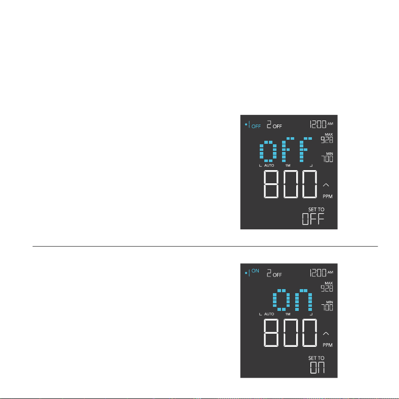
CONTROLLER MODES
Pressing the mode button will cycle through the controller’s available programming modes: OFF,
ON, CO
2
(Center and Zone), Fan (Center and Zone), and CYCLE (On and Off). Make sure to use
the appropriate mode for the device you’ve plugged in (ex. CO
2
mode for CO
2
generator).
ON MODE
Your device(s) will switch on regardless of CO
2
levels or time-based triggers.
OFF MODE
Your device(s) will switch off regardless of CO
2
levels or time-based triggers.
Jump back to OFF Mode anytime by holding the
MODE button while in other modes or settings.
PROGRAMMING
16
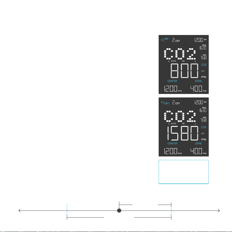
STEP 1
Ensure you are in the correct numbered outlet for the CO
2
generator you are using. Then navigate to the Center submode.
STEP 2
Use the up or down buttons to set the center
value and your desired CO
2
level. Press the mode button to
navigate to the Zone submode.
STEP 3
Use the up or down buttons to set the zone value and establish
an activation buffer around the center value.
Your CO
2
generator will switch on if the reading falls below this
threshold. When the reading rises above this trigger point, your
CO
2
generator will switch off.
In this example, the center value is 1200ppm and the zone
value is 400ppm.
Your CO
2
generator will switch on when the current CO
2
level is
below 1000ppm [1200 – (400/2)].
The CO
2
generator will turn off when the current CO
2
level is
above 1400ppm [1200 + (400/2)].
The set zone value is the
buffer around your set center
value that is equal to half its
setting. (ex. 400ppm. Buffer
zone is 1000-1400ppm).
PROGRAMMING
CO
2
MODE
CO
2
MODE
ON
CO
2
MODE
OFF
ZONE (400ppm)
THRESHOLD
CENTER (1200ppm)1000ppm 1400ppm
17
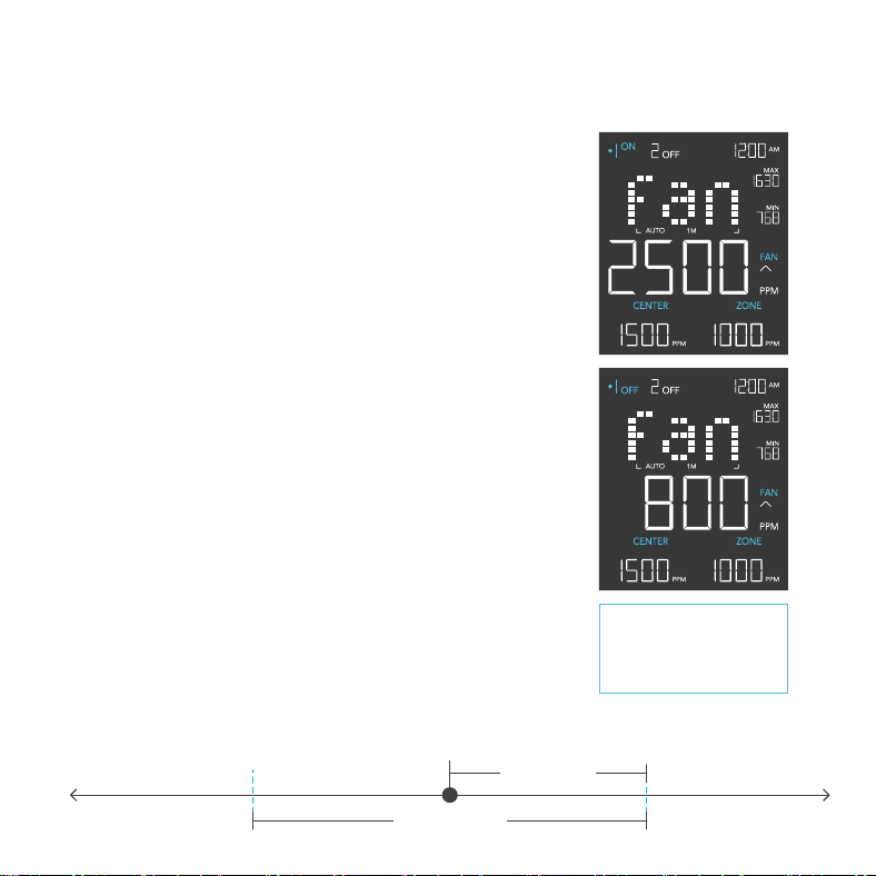
STEP 1
Ensure you are in the correct numbered outlet for the fan you
are using. Then navigate to the Center submode.
STEP 2
Use the up or down buttons to set the center value and
high CO
2
trigger. Press the mode button to navigate to the
Zone submode.
STEP 3
Use the up or down buttons to set the zone value and establish
an activation buffer around the center value.
Your fan will switch on if reading meets or exceeds this
threshold. When the reading falls below this trigger point, your
fan will switch off.
In this example, the center value is 1500ppm and the Set Zone
is 1000ppm.
Your fan will switch on when the current CO
2
level meets and
exceeds 2000ppm [1500 + (1000/2)].
The fan will turn off when the current CO
2
level is below
1000ppm [1500 - (1000/2)].
The set zone value is the
buffer around your set center
value that is equal to half its
setting. (ex. 1000ppm. Buffer
zone is 1000-2000ppm).
PROGRAMMING
FAN MODE
FAN MODE
ON
FAN MODE
OFF
ZONE (1000ppm)
THRESHOLD
CENTER (1500ppm)1000ppm 2000ppm
18
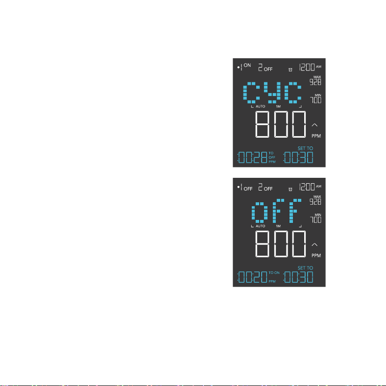
CYCLE MODE (ON AND OFF)
Sets an ON duration and an OFF duration for
your device to cycle through continuously. Press
the up or down button to set a countdown for
your device to turn on. Then press the mode
button and use the up or down button to set a
countdown for your device to turn off.
The countdown will begin if no buttons are
pressed for 5 seconds. Leaving the CYCLE
mode while the countdown is running will pause
it until you return to this mode.
PROGRAMMING
19
PROGRAMMING
CONTROLLER SETTINGS
Cycles through each of the controller’s settings: CO
2
CHART, NIGHT1 (Start and End),
Night 2 (Start and End), ALARM HIGH, ALARM LOW, DISPLAY BRIGHTNESS, CLOCK,
and CALIBRATION.
CO
2
CHART SETTING
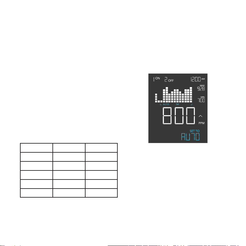
Changes the CO
2
chart’s time scales. Each
scale adjusts the chart to the selected duration
(ex. 1M = 1-minute spread)
Press the up or down button to cycle through
the following time scales:
CO
2
Timespan Time Per Unit
Auto
- -
1M 1 minute 5 sec.
1H 1 hour 5 min.
1D 1 day 2 hours
1W 1 week 0.5 days
20
PROGRAMMING
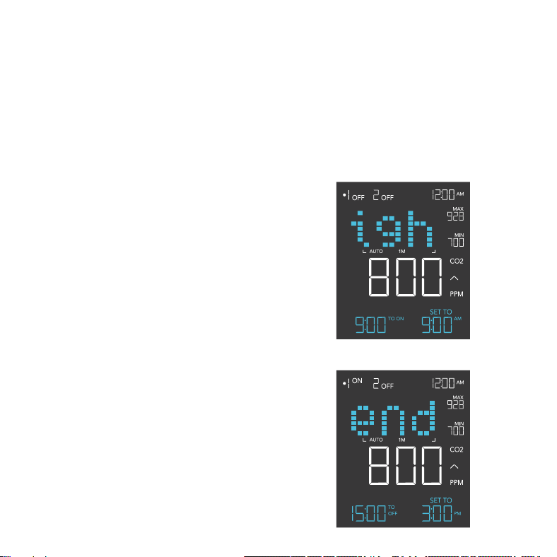
STEP 1 - NIGHT 1 START
Press the up or down button to first set up a
START clock-time in NIGHT 1 START to turn
your device off.
STEP 2 - NIGHT 1 END
Press the mode button to navigate to NIGHT
1 END and set an END clock-time to turn your
device on. This option will only appear if you set
NIGHT 1 programming.
STEP 3
Repeat these steps in NIGHT 2 if you have a
device plugged into Outlet 2.
The countdown will begin if no buttons are
pressed for 5 seconds. The time left on the
countdown before the next ON or OFF phase is
displayed on the lower left corner.
NIGHT SETTING
Shuts off your device within a set timeframe, turning back on when the schedule ends. This will
override all programming set in Outlet 1 or Outlet 2, even while away from this setting. Make sure
the system clock time is correct before adjusting this setting. NIGHT 1 programs Outlet 1 while
NIGHT 2 programs Outlet 2.
21
PROGRAMMING
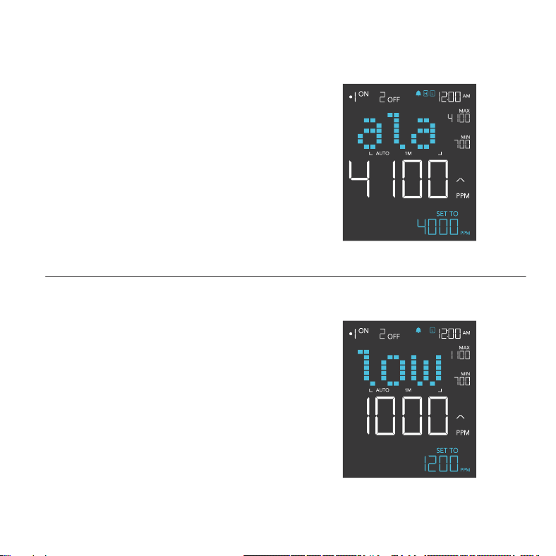
HIGH ALARM SETTING
Press the up and down button sets a high CO
2
alarm. The alarm will sound and its icon will flash if
the sensor’s reading exceeds the set CO
2
level.
To activate the alarm, leave the alarm mode. The
alarm will turn OFF if the sensor’s reading falls
below the trigger or if any button is pressed. You
can also set the alarm OFF by holding the up and
down buttons together.
LOW ALARM SETTING
Press the up and down button sets a low CO
2
alarm. The alarm will sound and its icon will flash if
the sensor’s reading falls below the set CO
2
level.
To activate the alarm, leave the alarm mode. The
alarm will turn OFF if the sensor’s reading rises
above the trigger or if any button is pressed. You
can also set the alarm OFF by holding the up and
down buttons together.
22
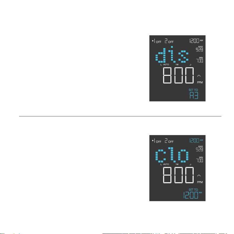
DISPLAY SETTING
Adjusts the display brightness and auto-dimming. Press
the up or down button to cycle through levels 1, 2, 3, A2
and A3; 3 being the highest brightness setting, while 1
is the lowest. In settings 1, 2 and 3, the display will stay
at that brightness level and will not automatically dim
the display.
A2 and A3 will set the brightness level at 2 and 3,
respectively, and will dim down the brightness level 1
when the controller is not being used after 15 seconds.
PROGRAMMING
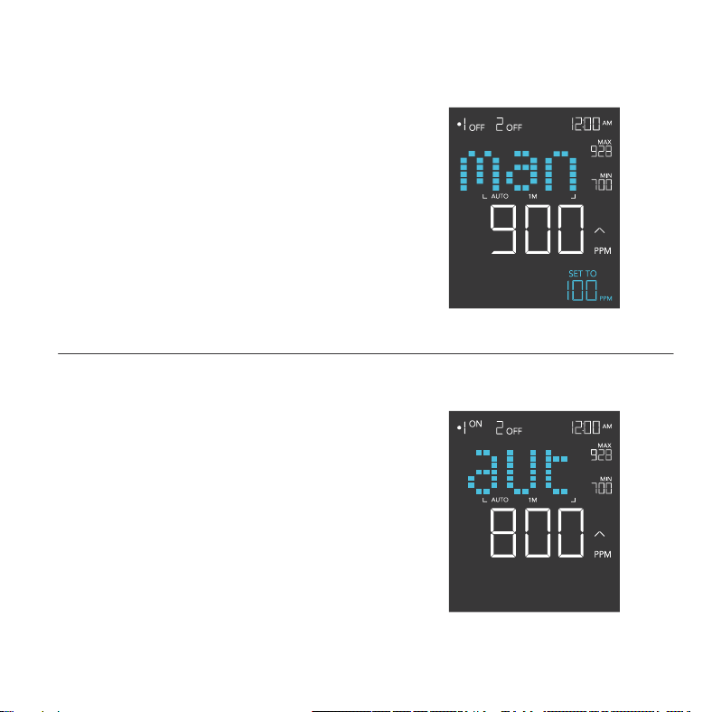
CLOCK SETTING
Adjusts the current clock time. Press the up or
down button to increase or decrease the time. Once
you cycle through 12:00 each time, the units will
automatically change to AM or PM. The clock time is
located at the lower left corner of the display.
23
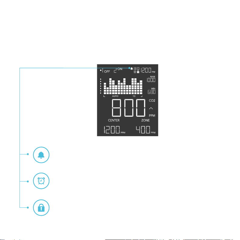
MANUAL CALIBRATION SETTING
Adjusts the CO
2
reading the sensor is measuring.
Press the up or down button to increase or decrease
the data figure in 10ppm increments.
The calibration cycle ranges from -500ppm to 500ppm
and will be applied to the sensor’s measurements.
AUTO-CALIBRATION SETTING
Automatically adjusts the CO
2
reading to 400ppm,
using outdoor conditions as a baseline, to correctly
display CO
2
levels.
Set the sensor in a shaded outdoor location away from
moisture. Hold the outlet button for 5 seconds to begin
the calibration. A 10-minute timer will appear on the
lower right corner.
Stay on this setting until the countdown concludes to
finish the calibration. Pressing the outlet button during
the auto-calibration will cancel the process.
PROGRAMMING
24
PROGRAMMING
ALERT / STATUS ICONS
On the top right of the display is the alert icon section. Icons may flash when the controller wishes
to alert you that a particular function or alarm is being triggered.
TIMER ALERT
This icon will flash when a countdown has completed for TIMER TO ON,
TIMER TO OFF, and CYCLE modes or the SCHEDULE setting.
ALARM ALERT
This icon will flash when the high or low alarm has been triggered.
DISPLAY LOCK ALERT
This icon will display when you lock the controller. The icon will flash and beep
if you attempt to adjust the controller while it is still locked.
25
OTHER SETTINGS
CONTROLLER LOCK
Holding the setting button will lock the controller in your
current mode. While your controller is locked, no parameters
may be adjusted, nor will you be able to switch modes.
Holding the setting button again will unlock the controller.
HOLD +
HIDE SCREEN
Lock the controller so no settings can be adjusted. See
above. Then press the setting button to turn the display off.
Pressing it again will turn the display back on. Programs will
still run in the background while the LCD screen is off.
PRESS +
RESET TO OFF/DEFAULT
Holding the up and down buttons together for 2 seconds will
reset the value of your current mode or controller setting
to OFF/Default. Pressing either the up or down button will
return to the previous value.
HOLD +
JUMP TO OFF MODE
Holding the mode button for 3 seconds while in any mode or
setting will automatically jump to OFF Mode. This function is
disabled if the controller is locked.
HOLD +
AUTO INCREASING OR DECREASING
Holding the up or down button will increase or decrease the
user setting automatically until you release them.
HOLD +
HOLD +
FACTORY RESET
Holding the mode, up, and down buttons together for
5 seconds will reset your controller and restore factory
settings. This clears all user parameters in each controller
mode and setting.
HOLD +
26
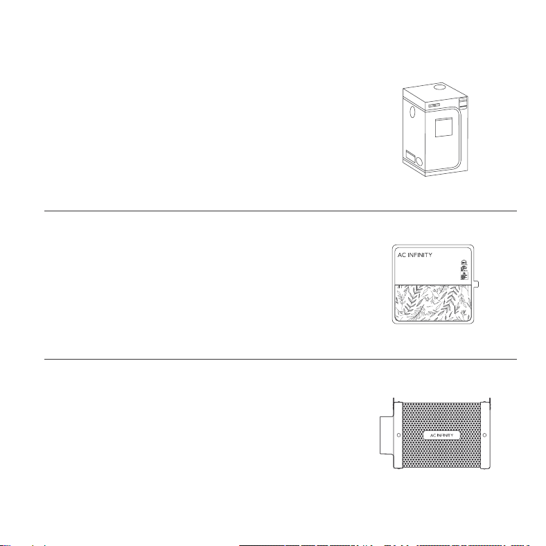
AC INFINITY PRODUCTS
Discover the latest innovations in environmental controls at acinfinity.com
Seedling Mats
The SUNCORE series is a line of seedling mat designed
to improve germination success and accelerate your
seeds’ growth process by emitting steady heat. Each mat
is lined with an innovative far-infrared film that provides
even heating distribution.
Carbon Filters
The duct carbon filter is designed to eliminate odors and
chemicals for grow tents and hydroponic spaces. It utilizes
premium grade Australian charcoal that features greater
absorption power and a longer lifespan. Enables maximum
airflow pass through as part of an intake or an exhaust system.
Advance Grow Tents
The CLOUDLAB series is a line of grow tents designed to create
ideal growing conditions and facilitate indoor plant cultivation
year-round. Features 2000D thick oxford canvas lined with inner
diamond patterned mylar that maximizes grow light luminosity,
and a reinforced frame with 150 lb. weight capacity. Includes a
mounting plate to install your AC Infinity controller onto.
27
WARRANTY
This warranty program is our commitment to you, the product sold by AC Infinity will be free from
defects in manufacturing for a period of two years from the date of purchase. If a product is found to
have a defect in material or workmanship, we will take the appropriate actions defined in this warranty
to resolve any issues.
The warranty program applies to any order, purchase, receipt, or use of any products sold by AC
Infinity or our authorized dealerships. The program covers products that have become defective,
malfunctioned, or expressively if the product becomes unusable. The warranty program goes into effect
on the date of purchase. The program will expire two years from the date of purchase. If your product
becomes defective during that period, AC Infinity will replace your product with a new one or issue you
a full refund.
The warranty program does not cover abuse or misuse. This includes physical damage, submersion
of the product in water, incorrect Installation such as wrong voltage input, and misuse for any reason
other than intended purposes. AC Infinity is not responsible for consequential loss or incidental
damages of any nature caused by the product. We will not warrant damage from normal wear such as
scratches and dings.
Contact our dealers department at dealers@acinfinity.com or (626) 838-4656 for more information
about our dealers and distributors program. Contact our customer service department at support@
acinfinity.com or 626-923-6399 for product and warranty assistance. Our business hours are Monday
through Friday, 9:00 am to 5:00 pm PST.
If you run into any issues with this product, contact us and we'll
happily issue a replacement or a full refund!

COPYRIGHT © 2023 AC INFINITY INC. ALL RIGHTS RESERVED
No part of the materials including graphics or logos available in this booklet may be copied, photocopied, reproduced,
translated or reduced to any electronic medium or machine readable form, in whole or in part, without specific
permission from AC Infinity Inc.




www.acinnity.com