
USER MANUAL
ADVANCE GROW SYSTEM
COMPLETE INDOOR PLANT KIT


3
PROUD TO PRESENT TO YOU
THE ADVANCE GROW SYSTEM
Thank you for choosing AC Infinity. As growers, we’ve dreamt of
applying commercial levels of automation technology to our systems,
scaled down for home growing, without the commercial level price
tag. Now we’ve made it possible.
This complete indoor growing system is the culmination of four years
of development, implementing smart controls into all the technology a
grow space uses to create a fully automated system. Each grow tent
kit contains equipment that is collectively rated to grow your desired
number of plants and can be controlled using its grow tent controller
or the AC Infinity app.
We are committed to product quality and friendly customer service,
so please contact us if you have any questions or suggestions.
Don’t forget to share your growing journey with this complete indoor
growing system on social media @acinfinityinc!
EMAIL
support@acinfinity.com
WEB
www.acinfinity.com
LOCATION
Los Angeles, CA

4
PRODUCT
Advance Grow Tent Kit (2x2) COMPACT
Advance Grow Tent Kit (2x2)
Advance Grow Tent Kit (2x4)
Advance Grow Tent Kit (3x3)
Advance Grow Tent Kit (4x4)
Advance Grow Tent Kit (5x5)
MODEL
AC-PKA22
AC-PKB22
AC-PKB24
AC-PKB33
AC-PKB44
AC-PKB55
UPC
819137022829
819137022836
819137022843
819137022850
819137022867
819137024038
MANUAL CODE PK2210X1

5
MANUAL INDEX
Manual Index .................................................................................................
Product Warning ...........................................................................................
Product Contents .........................................................................................
Quick Build Guide ........................................................................................
CLOUDLINE: Mixed Flow Inline Fan System ..............................................
Duct Carbon Filter: Premium Australian Charcoal ....................................
Product Contents ...................................................................................
Tent Setup .............................................................................................
Controller Plate Setup ...........................................................................
Mounting Guide .....................................................................................
Ventilation Guide ...................................................................................
Configuration Setup ...............................................................................
Product Contents ...................................................................................
Mounting ................................................................................................
Overhead Hanging ................................................................................
Motor Cap ..............................................................................................
Configuration Setup ...............................................................................
Cleaning ................................................................................................
Product Contents ...................................................................................
Installation .............................................................................................
Overhead Hanging ................................................................................
Configuration Setup ...............................................................................
Maintenance ..........................................................................................
Page 5
Page 7
Page 8
Page 10
Page 12
Page 13
Page 15
Page 20
Page 22
Page 23
Page 24
Page 26
Page 27
Page 28
Page 33
Page 36
Page 37
Page 38
Page 40
Page 41
Page 42
Page 43
Page 47
Page 50
Page 52
Page 53
Page 55
Page 57
Page 60
Page 63
Page 65
Page 67
IONBOARD / IONFRAME EVO: Grow Light System ..................................
Product Contents ...................................................................................
Installation .............................................................................................
Driver Mounting: IONFRAME EVO ........................................................
Overhead Hanging ................................................................................
Powering and Setup ..............................................................................
Starter Guide .........................................................................................
Programming .........................................................................................
CLOUDLAB: Advance Grow Tent ...............................................................

6
CLOUDRAY: Oscillation Fan System ..........................................................
Warranty ........................................................................................................
Product Contents ...................................................................................
Recommended Usage ...........................................................................
Installation .............................................................................................
Cleaning ................................................................................................
Programming .........................................................................................
CONTROLLER 69 PRO: UIS
TM
Controller ....................................................
Product Contents ...................................................................................
Powering and Setup ..............................................................................
Mounting ................................................................................................
UIS
TM
Platform ........................................................................................
UIS
TM
Compatibility ................................................................................
Adding More Devices ............................................................................
Programming .........................................................................................
Other Settings ........................................................................................
Download the App .................................................................................
Add a Device .........................................................................................
Frequently Asked Questions .................................................................
Page 68
Page 69
Page 70
Page 71
Page 74
Page 76
Page 78
Page 79
Page 80
Page 82
Page 84
Page 85
Page 86
Page 88
Page 112
Page 113
Page 114
Page 121
Page 124
MANUAL INDEX
7
Ensure your power source conforms to the electrical requirements of this product.
Check your local code restrictions for additional safety measures that may be needed for a
proper code compliant installation.
Read all instructions before installing and using this product.
If you are unfamiliar or have doubts about performing this product’s installation, seek the
services of a qualified, trained, and licensed professional. Inappropriate installation will void this
product’s warranty.
Do not attempt to hardwire this product. Performing any retrofitting actions may result in
personal injury and/or electrical damage, and will void this product’s warranty.
This product must not be used in potentially hazardous locations such as flammable, explosive,
chemical-laden, or wet atmospheres.
Ducted products must always be vented to outdoor areas.
Do not cover power cords with rugs or other fabric materials.
This product has rotating parts. Safety precautions should be exercised during the installation,
operation, and maintenance of this product.
Do not insert or allow fingers or foreign objects to enter any ventilation or exhaust openings as
it may cause electric shock, fire, or damage to this product. Do not block or tamper with this
product in any manner while it is in operation.
Do not depend on the on/off programming as the sole means of shutting power from this
product. Unplug the power cord before installing, servicing, or moving this product.
Do not operate this product while its cord is damaged, or if it malfunctions, has been dropped,
or is damaged in any manner.
1.
2.
3.
4.
5.
6.
7.
8.
9.
10.
11.
12.
PRODUCT WARNING
TO REDUCE THE RISK OF FIRE, ELECTRIC SHOCK, OR INJURY TO
PERSONS, OBSERVE THE FOLLOWING:
8
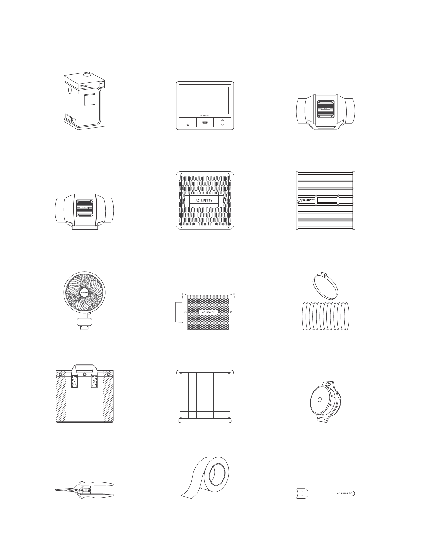
PRODUCT CONTENTS
OVERVIEW
CONTROLLER 69 PRO
UIS Controller
BOX B
CLOUDLINE
Inline Fan
BOX C
(NOT included in AC-PKB55)
CLOUDLAB
Advance Grow Tent
BOX A
ALUMINUM
DUCTING TAPE
BOX I
HOOK AND LOOP
CABLE TIES
BOX I
STAINLESS STEEL
PRUNING SNIPS
BOX I
ELASTIC
TRELLIS NETTING
BOX I
GARDEN PLANT
TWIST TIES
BOX I
FABRIC POTS,
5 gal.
BOX H
INLINE
CARBON FILTER
BOX F
DUCTING
AND CLAMPS
BOX G
CLOUDRAY
Clip Fan
BOX E
IONBOARD
LED Grow Light
BOX D
(NOT included in AC-PKB55)
IONFRAME EVO
LED Grow Light
BOX D
(ONLY included in AC-PKB55)
CLOUDLINE PRO
Inline Fan
BOX C
(ONLY included in AC-PKB55)
9
PRODUCT CONTENTS
DETAILS
BOX A
GROW TENT
BOX B
GROW TENT
CONTROLLER
BOX C
INLINE FAN
BOX D
LED GROW LIGHT
BOX E
CLIP-ON FAN
BOX F
CARBON FILTER
BOX G
DUCTING
BOX H
FABRIC POTS
BOX I
TRELLIS
NETTING
BOX I
TWIST TIES
BOX I
PRUNING SNIPS
BOX I
DUCTING TAPE
BOX I
HOOK AND
LOOP TIES
BOX G
CLAMPS
BOXES C & F
HANGING STRAPS
BOXES D
ROPE CLIP HANGERS
BOXES D
CONTROLLER CORD
BOXES E
L-SHAPED
CONTROLLER CORD
CLOUDLAB 422,
24” x 24” x 48”
x1
CONTROLLER 69 PRO,
4 Ports
x1
CLOUDLINE A4,
Inline Fan 4 in.
x1
IONBOARD S22,
2x2 Coverage
x1
CLOUDRAY S6,
Oscillating Clip Fan
x1
Inline Carbon Filter, 4 in.
x1
4 in. Flexible Ducting,
8 ft. Length
x1
Fabric Pots, 5 gal.
x2
Elastic Trellis Netting
2’ x 2’
x1
Wire Plant Tie, Black
x1
Micro-Tip Shears
x1
Aluminum Tape, 5 ft.
x1
Hook and Loop
Cable Tie
x10
4 in. Silver Metal Clamp
x2
Nylon Hanging Straps
x2 per box
Adjustable Hangers
x2
UIS Male-Male
Controller Cord
x1
UIS Male-Male
Controller Cord
x1
CLOUDLAB 722,
24” x 24” x 72”
x1
CONTROLLER 69 PRO,
4 Ports
x1
CLOUDLINE A4,
Inline Fan 4 in.
x1
IONBOARD S22,
2x2 Coverage
x1
CLOUDRAY S6,
Oscillating Clip Fan
x1
Inline Carbon Filter, 4 in.
x1
4 in. Flexible Ducting,
8 ft. Length
x1
Fabric Pots, 5 gal.
x2
Elastic Trellis Netting
2’ x 2’
x1
Wire Plant Tie, Black
x1
Micro-Tip Shears
x1
Aluminum Tape, 5 ft.
x1
Hook and Loop
Cable Tie
x10
4 in. Silver Metal Clamp
x2
Nylon Hanging Straps
x2 per box
Adjustable Hangers
x2
UIS Male-Male
Controller Cord
x1
UIS Male-Male
Controller Cord
x1
CLOUDLAB 642,
24” x 48” x 72”
x1
CONTROLLER 69 PRO,
4 Ports
x1
CLOUDLINE A6,
Inline Fan 6 in.
x1
IONBOARD S24,
2x4 Coverage
x1
CLOUDRAY S6,
Oscillating Clip Fan
x1
Inline Carbon Filter, 6 in.
x1
6 in. Flexible Ducting,
8 ft. Length
x1
Fabric Pots, 5 gal.
x4
Elastic Trellis Netting
2’ x 4’
x1
Wire Plant Tie, Black
x1
Micro-Tip Shears
x1
Aluminum Tape, 5 ft.
x1
Hook and Loop
Cable Tie
x10
6 in. Silver Metal Clamp
x2
Nylon Hanging Straps
x2 per box
Adjustable Hangers
x2
UIS Male-Male
Controller Cord
x1
UIS Male-Male
Controller Cord
x1
CLOUDLAB 733,
36” x 36” x 72”
x1
CONTROLLER 69 PRO,
4 Ports
x1
CLOUDLINE A6,
Inline Fan 6 in.
x1
IONBOARD S33,
3x3 Coverage
x1
CLOUDRAY S6,
Oscillating Clip Fan
x1
Inline Carbon Filter, 6 in.
x1
6 in. Flexible Ducting,
8 ft. Length
x1
Fabric Pots, 5 gal.
x6
Elastic Trellis Netting
3’ x 3’
x1
Wire Plant Tie, Black
x1
Micro-Tip Shears
x1
Aluminum Tape, 5 ft.
x1
Hook and Loop
Cable Tie
x10
6 in. Silver Metal Clamp
x2
Nylon Hanging Straps
x2 per box
Adjustable Hangers
x2
UIS Male-Male
Controller Cord
x1
UIS Male-Male
Controller Cord
x1
CLOUDLAB 844,
48” x 48” x 80”
x1
CONTROLLER 69 PRO,
4 Ports
x1
CLOUDLINE A6,
Inline Fan 6 in.
x1
IONBOARD S44,
4x4 Coverage
x1
CLOUDRAY S6,
Oscillating Clip Fans
x2
Inline Carbon Filter, 6 in.
x1
6 in. Flexible Ducting,
8 ft. Length
x1
Fabric Pots, 5 gal.
x8
Elastic Trellis Netting
4’ x 4’
x1
Wire Plant Tie, Black
x1
Micro-Tip Shears
x1
Aluminum Tape, 5 ft.
x1
Hook and Loop
Cable Tie
x10
6 in. Silver Metal Clamp
x2
Nylon Hanging Straps
x2 per box
Adjustable Hangers
x2
UIS Male-Male
Controller Cord
x1
UIS Male-Male
Controller Cord
x2
Advance Grow
Tent Kit (2x2)
COMPACT
AC-PKA22
Advance Grow
Tent Kit (2x2)
AC-PKB22
Advance Grow
Tent Kit (2x4)
AC-PKB24
Advance Grow
Tent Kit (3x3)
AC-PKB33
Advance Grow
Tent Kit (4x4)
AC-PKB44
Advance Grow
Tent Kit (5x5)
AC-PKB55
CLOUDLAB 866,
60” x 60” x 80”
x1
CONTROLLER 69 PRO,
4 Ports
x1
CLOUDLINE PRO T6,
Inline Fan 6 in.
x1
IONFRAME EVO8,
5x5 Coverage
x1
CLOUDRAY S6,
Oscillating Clip Fans
x2
Inline Carbon Filter, 6 in.
x1
6 in. Flexible Ducting,
8 ft. Length
x1
Fabric Pots, 5 gal.
x12
Elastic Trellis Netting
5’ x 5’
x1
Wire Plant Tie, Black
x1
Micro-Tip Shears
x1
Aluminum Tape, 5 ft.
x1
Hook and Loop
Cable Tie
x10
6 in. Silver Metal Clamp
x2
Nylon Hanging Straps
x2 per box
Adjustable Hangers
x2
UIS Male-Male
Controller Cord
x1
UIS Male-Male
Controller Cord
x2
10
QUICK BUILD GUIDE
1
Build the Grow Tent (BOX A).
Refer to pages 12-25.
Install the Inline Fan with Straps (BOX
C), Ducting and Clamps (BOX G) to your
preferred configuration.
Refer to pages 26-39.
You may connect and hang
the Carbon Filter with Straps
(BOX F) to your ductwork.
Refer to pages 40-51. Use
Duct Tape (BOX I) to seal any
gaps in the ducting.
Clamp the Clip Fan
(BOX E) onto the tent
frame. Refer to pages
68-77.
2
3 5
Hang the Grow Light
using Rope Hangers
(BOX D) by the roof
support beams. Refer to
pages 52-67. Turn the
knob to “UIS” to pair and
connect with the controller.
4
11
Add potting mix and plant seeds into the Fabric Pot (BOX H), and set it inside of the grow
tent to finish the build.
The Grow Tent Controller is pre-programmed with the following settings:
Use the Hook and Loop Ties (BOX I)
to manage the wires.
Plug all the electronic devices
into available AC outlets.
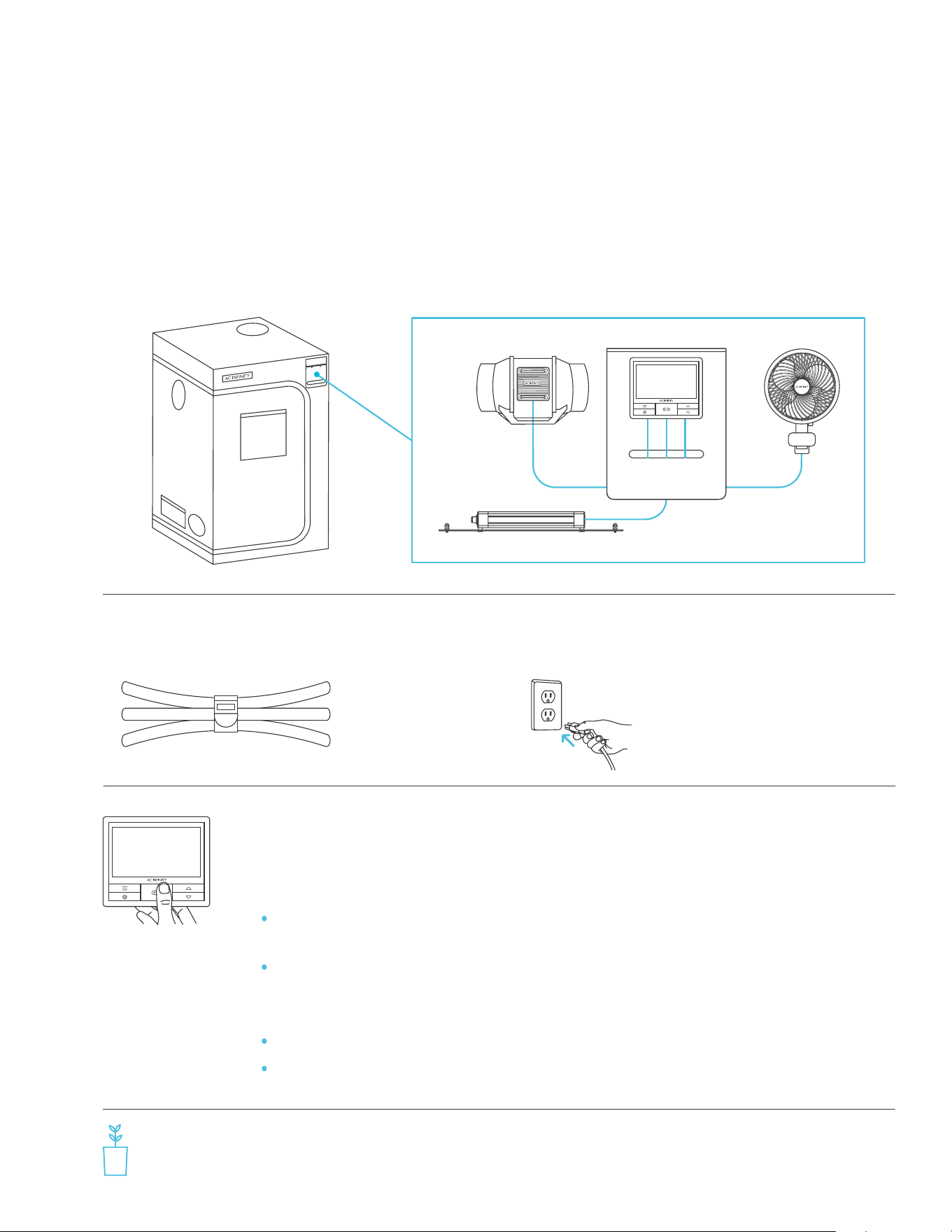
Mount the Grow Tent Controller (BOX B) onto the Controller Plate (BOX A).
Refer to page 20.
Set the Grow Tent Controller’s (BOX B) clock time to your local time. Refer to
page 102.
Plug the probe into the probe port. Plug the Inline Fan’s controller cable (BOX C)
into Port 1, the Grow Light’s controller cable (BOX D) into Port 2, and the Clip Fan’s
controller cable (BOX E) into Port 3. Plug the second Clip Fan’s controller cable (BOX
E) into Port 4 (AC-PKB44 and AC-PKB55 models only). Refer to page 80.
7 8
6
Port 1 – Inline Fan set to Fan Speed Level 5 scheduled between 6:00pm
and 12:00pm, and to Level 2 scheduled between 12:00pm and 6:00pm.
Port 2 – Grow Light set to Brightness Intensity Level 10 scheduled
between 6:00pm and 12:00pm and to Level 0 scheduled between
12:00pm and 6:00pm.
Port 3 – Clip Fan set to Level 5.
Port 4 – Clip Fan set to Level 5 (AC-PKB44 and AC-PKB55 models only).
9
QUICK BUILD GUIDE
12
CLOUDLAB SERIES
ADVANCE GROW TENT
13
ADVANCE GROW TENT
PRODUCT CONTENTS
CONTROLLER
MOUNTING
PLATE
x1 x1 x1 x1 x1 x1
WALL HANG
SCREWS WITH
NUTS
x4 x4 x4 x4 x4 x4
CONTROLLER
HOOK AND
LOOP PADS
x6 x6 x6 x6 x6 x6
NYLON
HANGING
STRAPS
x2 x2 x2 x2 x2 x2
CONTROLLER
PLATE BOLTS
WITH NUTS
x4 x4 x4 x4 x4 x4
Advance Grow
Tent Kit (2x2)
COMPACT
AC-PKA22
Advance Grow
Tent Kit (2x2)
AC-PKB22
Advance Grow
Tent Kit (2x4)
AC-PKB24
Advance Grow
Tent Kit (3x3)
AC-PKB33
Advance Grow
Tent Kit (4x4)
AC-PKB44
Advance Grow
Tent Kit (5x5)
AC-PKB55
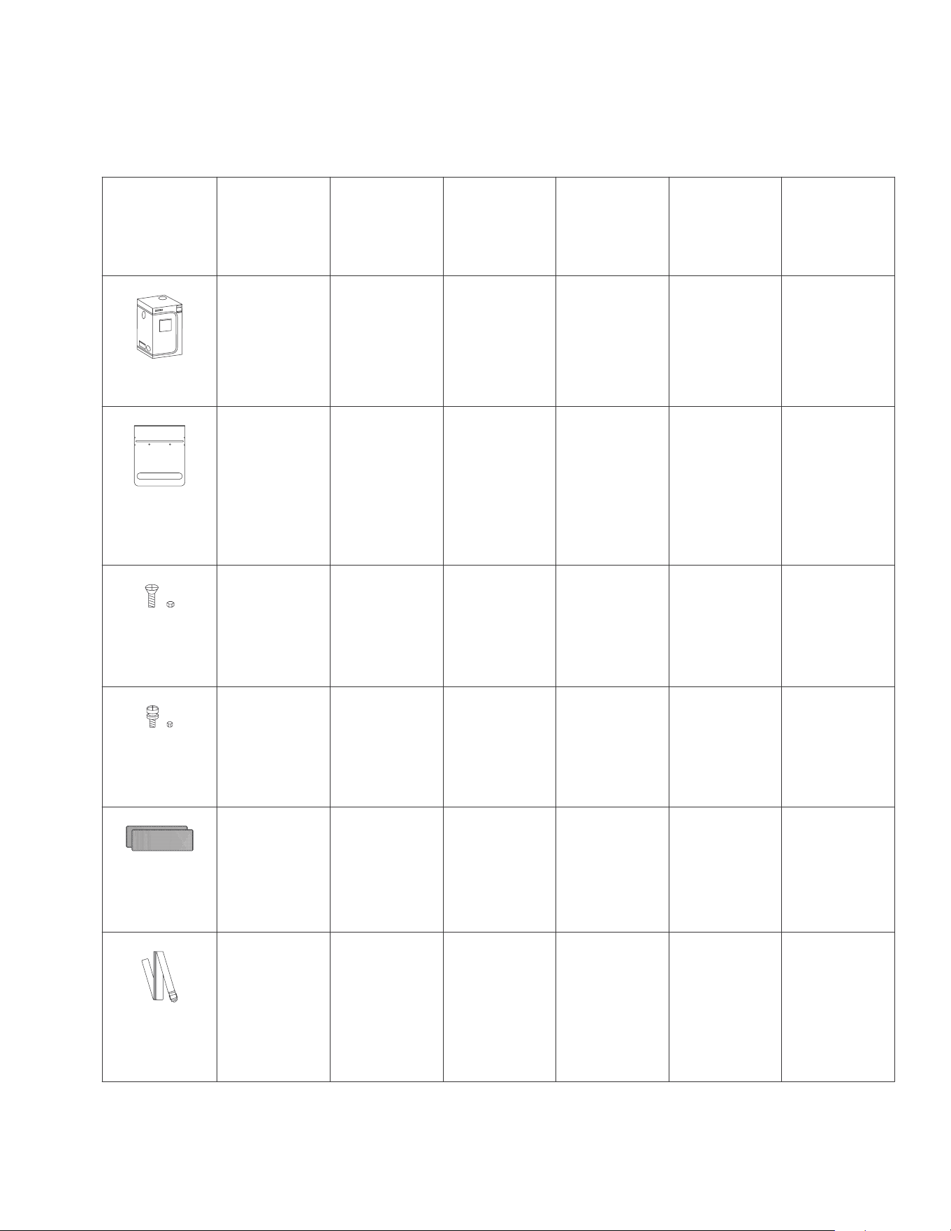
GROW TENT
CLOUDLAB 422,
24” x 24” x 48”
x1
CLOUDLAB 722,
24” x 24” x 72”
x1
CLOUDLAB 642,
24” x 48” x 72”
x1
CLOUDLAB 733,
36” x 36” x 72”
x1
CLOUDLAB 844,
48” x 48” x 80”
x1
CLOUDLAB 866,
60” x 60” x 80”
x1
14
PRODUCT CONTENTS
CLOUDLAB
x8
A
x4 x4 x8 x1 x2
B
C
D1
E F
x8
A
x4 x4 x8 x2 x2
B
C
E F
D1
CLOUDLAB SERIES Included only with
CLOUDLAB 422
CLOUDLAB 722
AC-CBA422
AC-CBA722
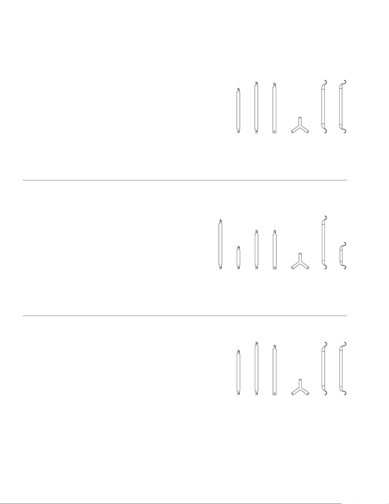
FRAME POLES
CLOUDLAB SERIES Included only with
CLOUDLAB 733
CLOUDLAB 844
CLOUDLAB 866
AC-CBA733
AC-CBA844
AC-CBA866
FRAME POLES
CLOUDLAB SERIES Included only with
CLOUDLAB 642 AC-CBA642
FRAME POLES
x4
A1
x4 x4 x8 x1 x2
B
C
E
F
x4
A2
D
NOTE: Pole lengths may vary between all models.
15
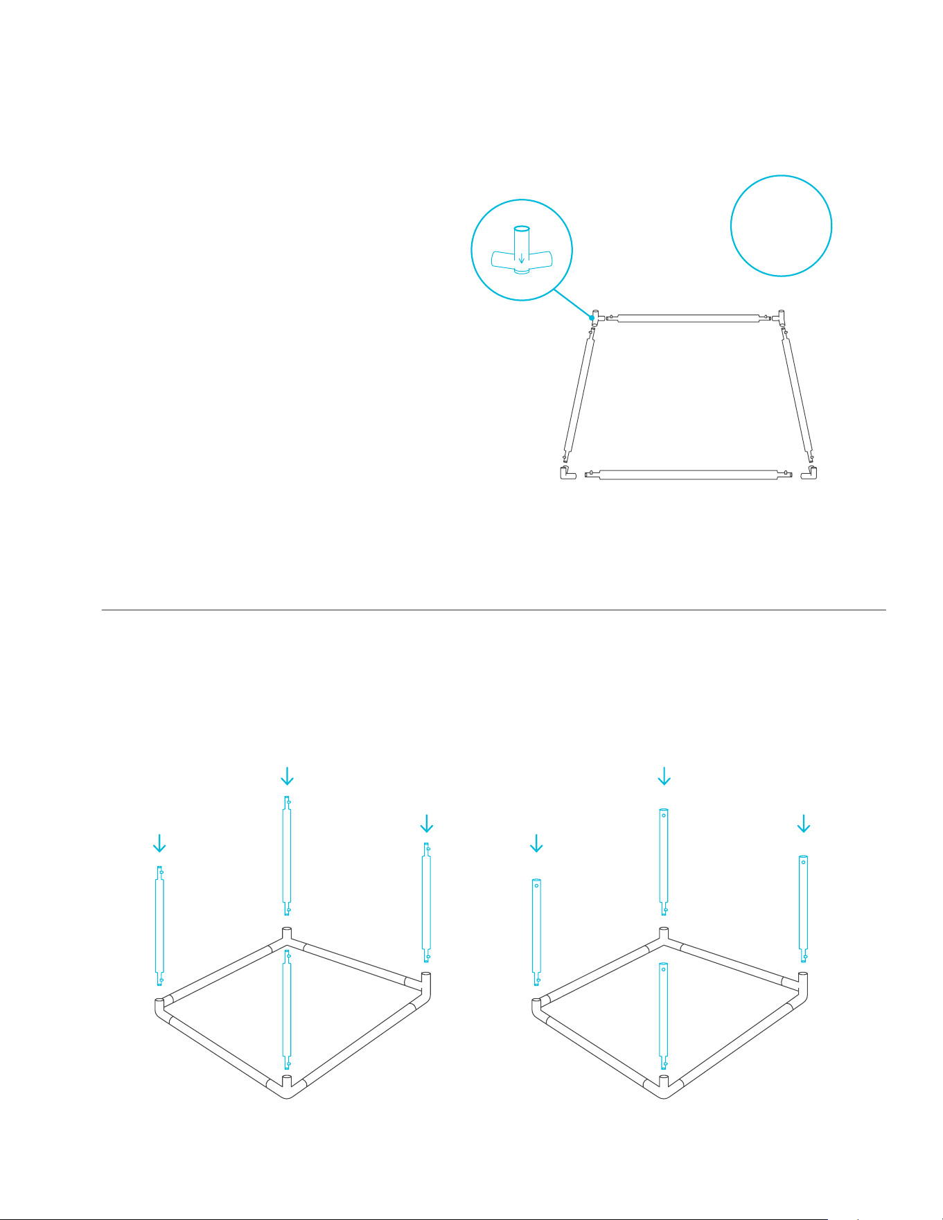
STEP 1
Insert the eight (A) poles* and into the
floor end of the corner (D1) pieces to
create two bases.
When assembling, make sure the feet of
each corner (D1) piece faces the floor
with the arrow facing down.
STEP 2
Insert the four (B) poles into Base One.
Insert the four (C) poles into Base Two.
D1
D1
D1
D1
X2
A / A1
A / A1
A / A2 A / A2
*Poles in CLOUDLAB 642 are labeled A1 & A2.*
TENT SETUP
CLOUDLAB
Base One Base Two
B
B
B
B
C
C
C
C
16
CLOUDLAB
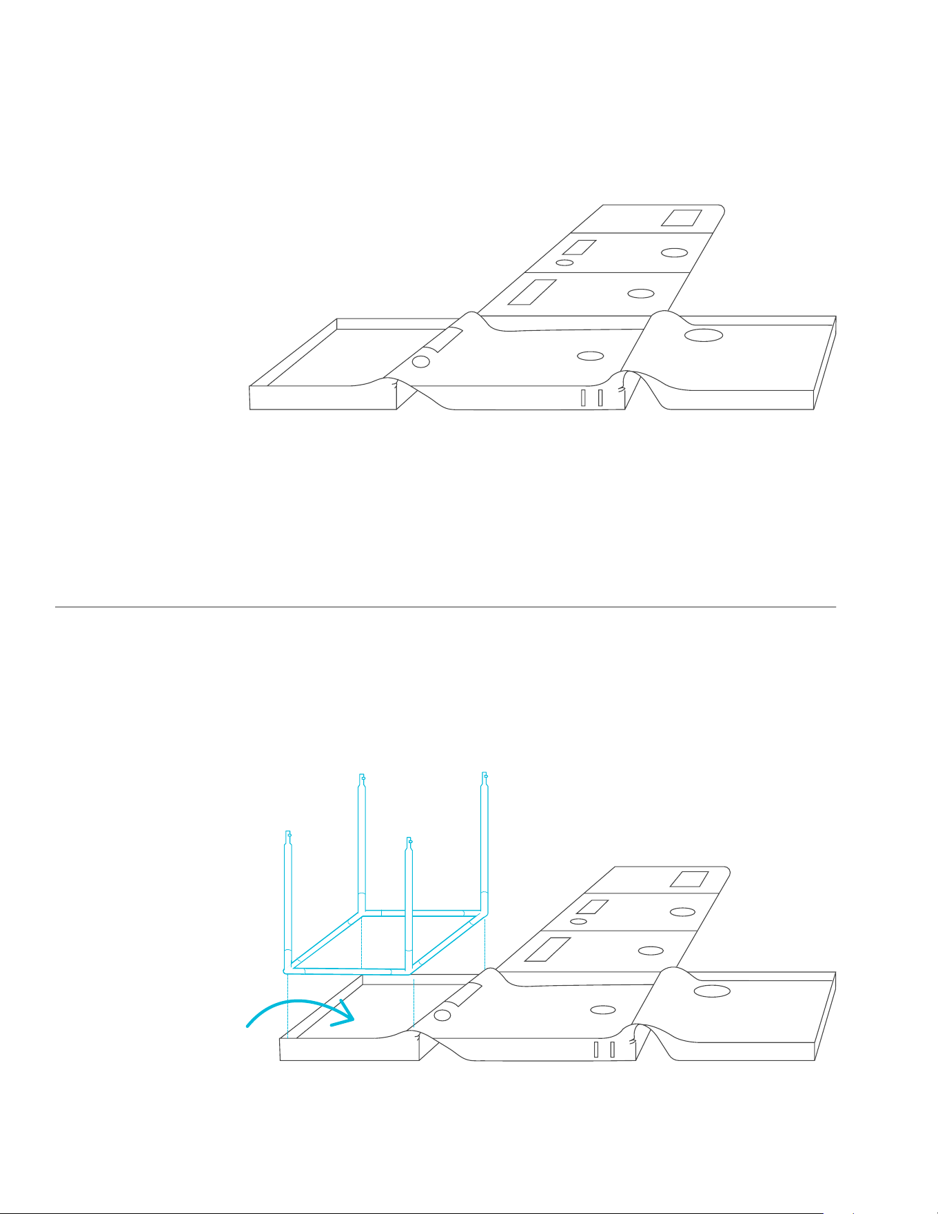
STEP 3
Unzip the tent so that three of the walls
lay flat.
Floor
Roof
Door
STEP 4
Guide Base One into the floor of the
tent, making sure its corners meet the
tent’s corners.
TENT SETUP
Floor
Base One
17
CLOUDLAB
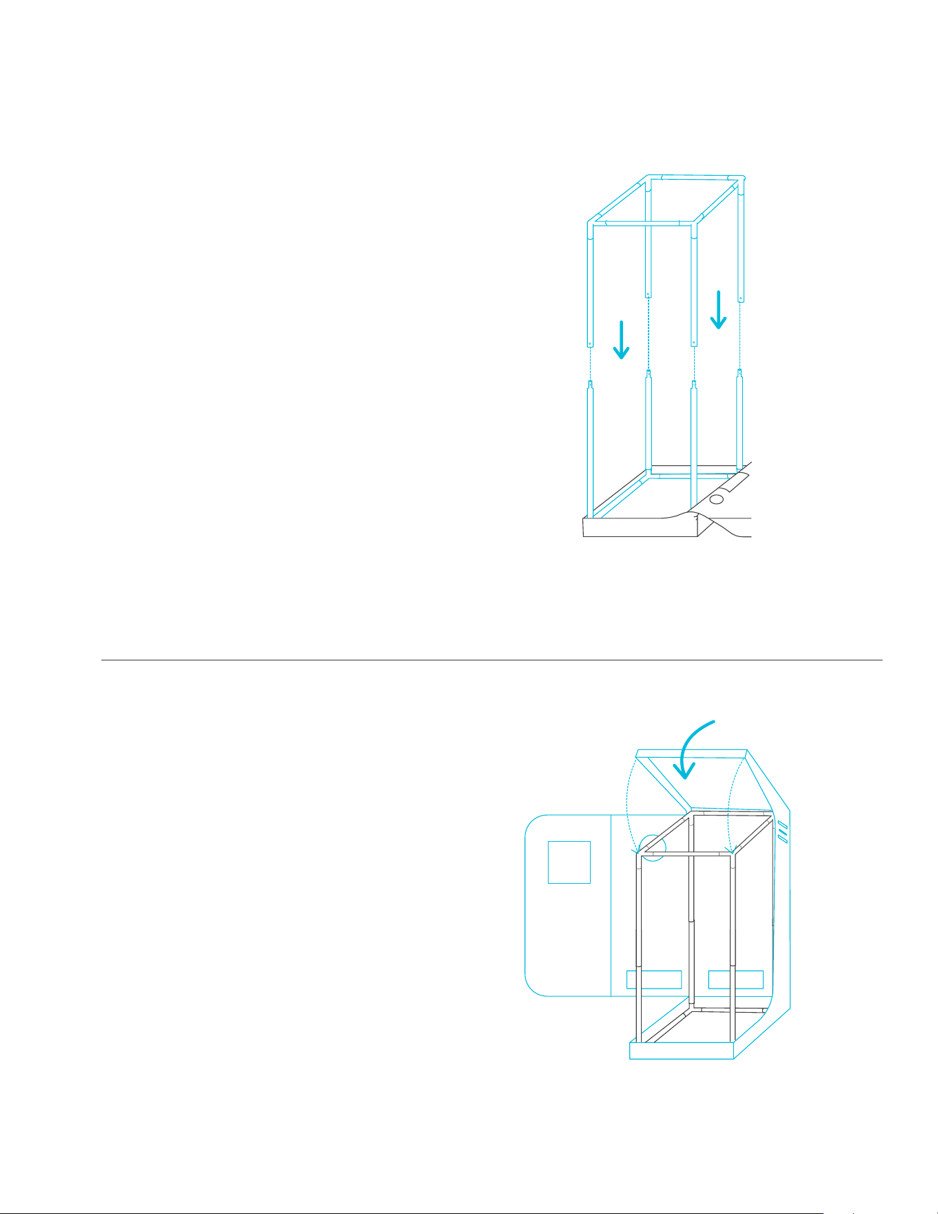
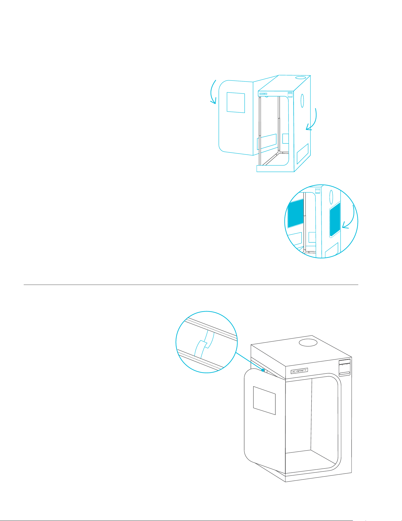
STEP 6
Pull the roof over the assembled frame.
STEP 5
Insert the poles of Base Two into the poles
of Base One to complete the frame.
Two people are recommended for this portion of the tent assembly.
Two people are recommended for this portion of the tent assembly.
TENT SETUP
Base One
Base Two
B
B
B
C
C
C
18
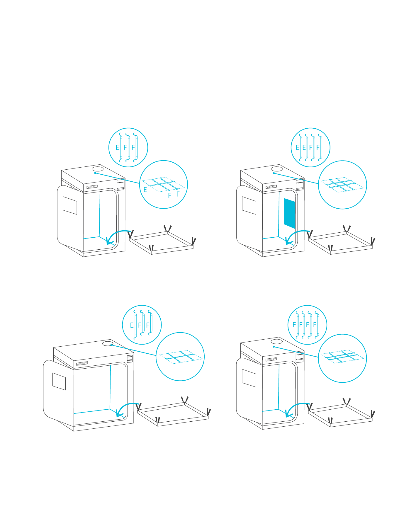
CLOUDLAB
STEP 8
You can neatly hold the window wall
open any time by using its attached hook
and loop strap.
STEP 7
Pull the upper and lower zippers to close
the walls and door.
TENT SETUP
*CLOUDLAB 733 / 844 / 866 are built with additional side doors.
19
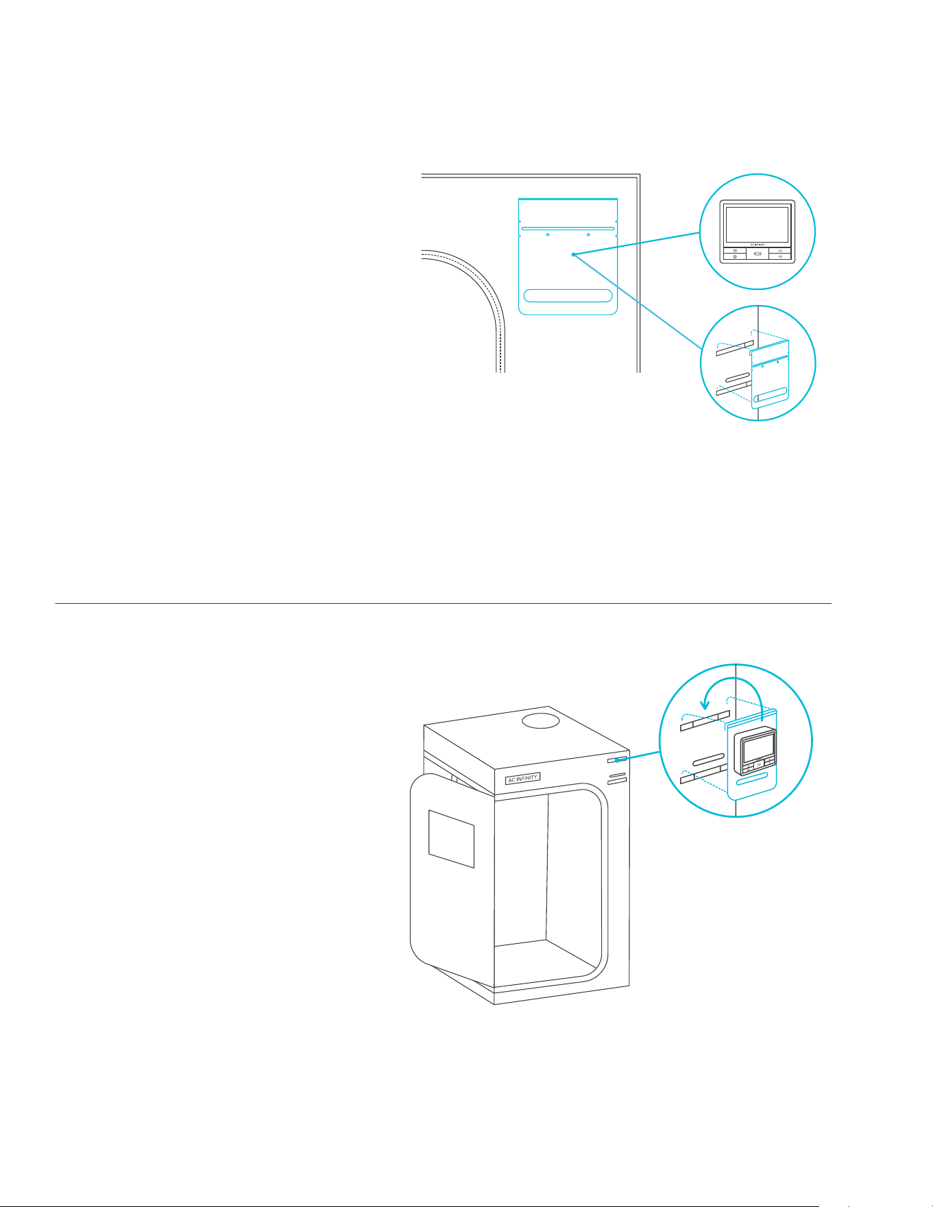
CLOUDLAB
STEP 9
Add the roof support beams (E) then
(F). Insert the spill pool into the tent and
secure the hook and loop straps around
the poles.
TENT SETUP
CLOUDLAB 642
CLOUDLAB 844 / 866
CLOUDLAB 422 / 722 CLOUDLAB 733
*CLOUDLAB 733 / 844 / 866 are built with additional side doors.
E
F
F
E
E
F
F
E
F
F
20
STEP 1
Magnetically mount the controller onto
the bracket.
Refer to pages 82-83 for additional
controller mounting methods.
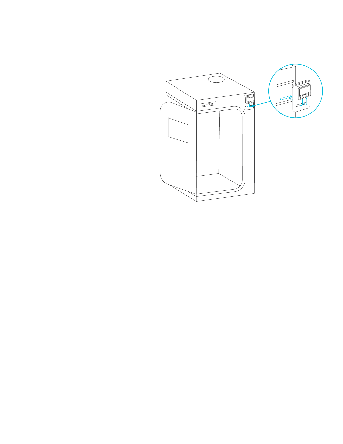
STEP 2
Slide the controller bracket assembly into
the tent straps.
CLOUDLAB 866 will include a lower third
strap for an alternate mounting location.
CONTROLLER PLATE SETUP
CLOUDLAB
21
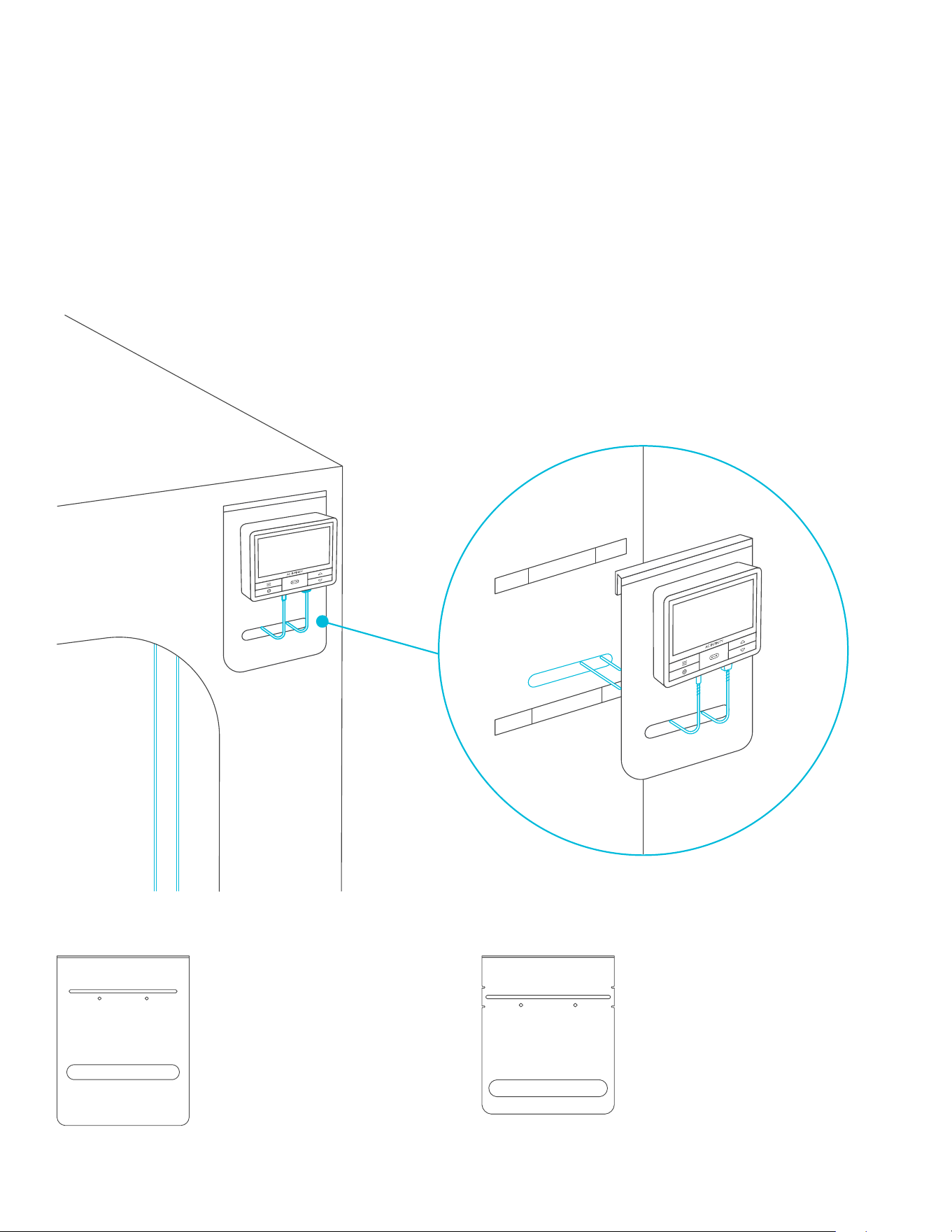
STEP 3
Route your inline duct fan’s power
connector through the opening inside
and plug it into your controller.
Plug the probe into the controller and
route its cables through the opening.
CONTROLLER PLATE SETUP
CLOUDLAB
22
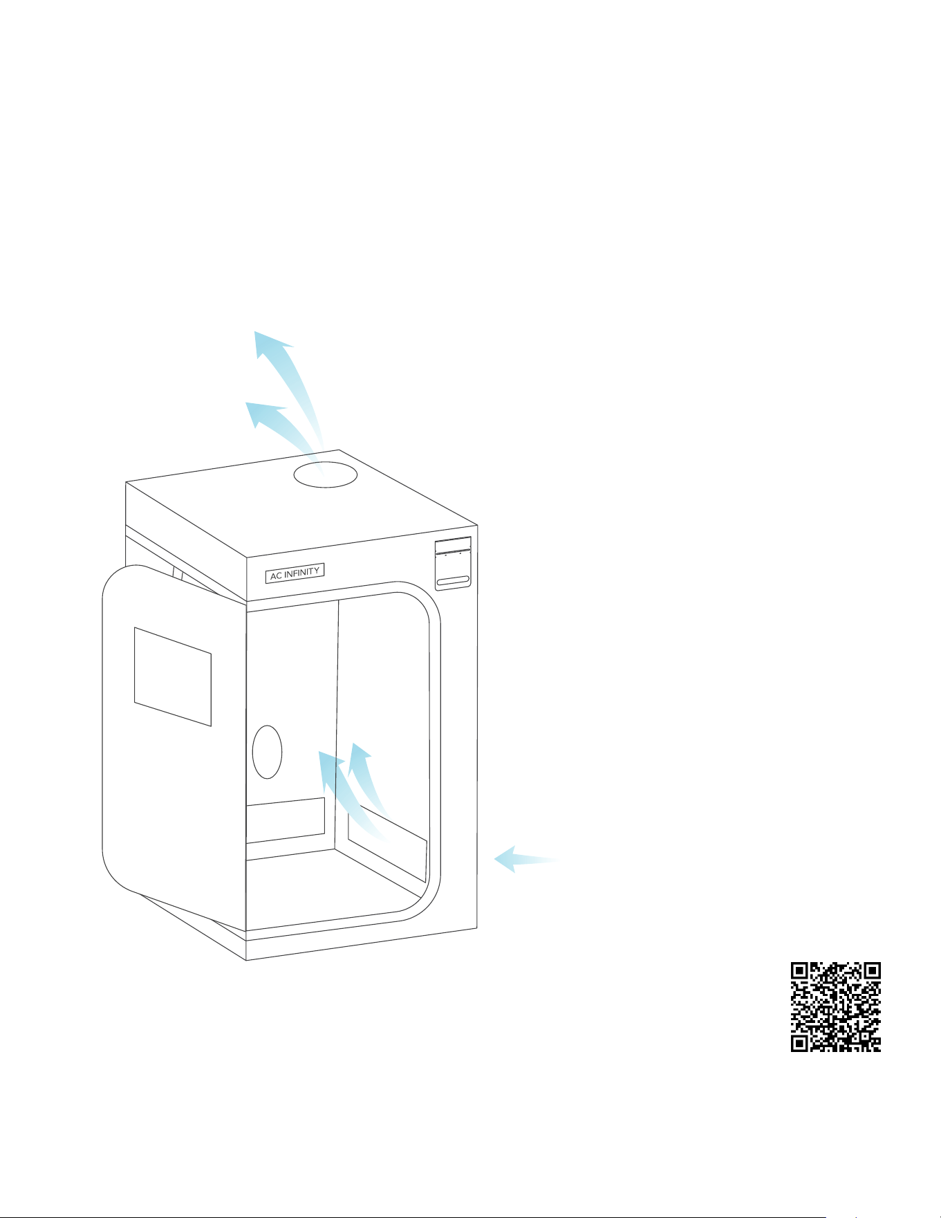
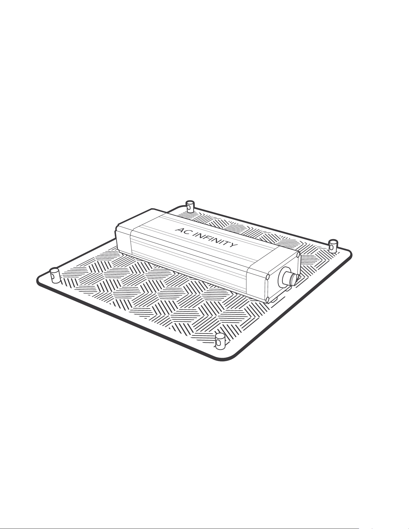
CONTROLLER PLATE
This grow tent includes a steel plate with a mounting slot for AC Infinity controllers. Mount
your controller to the corresponding areas on the plate’s slot. Route its wires through the oval
opening and through the grow tent’s flap. Some controller models may contain a hidden magnet
on the backside, which can stick onto this plate without screws.
MOUNTING GUIDE
CLOUDLAB
ONLY INCLUDED WITH
CLOUDLAB 422
CLOUDLAB 722
CLOUDLAB 733
ONLY INCLUDED WITH
CLOUDLAB 642
CLOUDLAB 844
CLOUDLAB 866
23
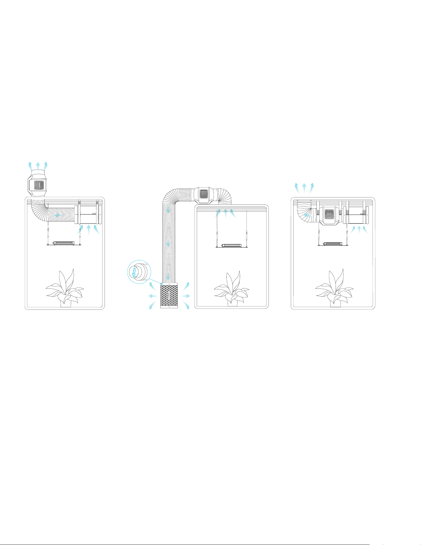
INLINE FAN AND GROW LIGHT
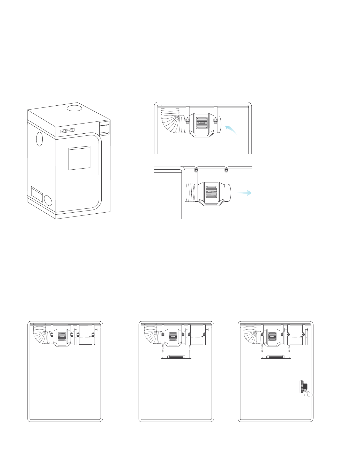
First hang your inline duct fan to be used as an exhaust fan by the roof support beams. Position
the intake fan at the bottom end so the intake air will be passive through the bottom vents. If you
are installing a carbon filter inside, use the included straps to hang the carbon filter.
Then install your grow light. You may use rope clip hangers to install these products.
INTAKE HOLES
Introduce fresh air by using one of the two
ventilation holes at the bottom of the grow
tent. Open a passive intake screen or create
active intake by attaching an additional inline
fan to a duct port.
DOUBLE-SIDED CINCHES
Install any necessary duct tubes onto the
ducting ports. Use the cinches on either end
to secure the duct tubes onto the grow tent.
NEED MORE INFORMATION?
Scan the QR code or visit
www.acinfinity.com for more
guides and tutorials.
VENTILATION GUIDE
CLOUDLAB
24
LIGHT AND VENTILATION PLACEMENT
There are many ways to configure these components to bring airflow into your grow space.
A typical setup places the fan and the filter inside, which makes it easier to manage while
dampening the fan noise. Both can be situated in any order within the ventilation chain if air is
being pulled out of your grow space.
For example, your grow lights might get in the way of your cooling equipment. In this case, you
may set the fan and/or filter outside of your grow tent.
We recommend setting your extraction fan at the highest point possible. Since heat rises to the
top, exhausting that hot air at that point will make the ventilation process efficient. Your carbon
filter will also perform better if it’s positioned at the highest point.
Fan and Filter Are
Placed Outside the Tent
Fan and Filter Are
Placed Inside the Tent
Fan Is Placed
Outside the Tent
Pre-filter can
be placed
inside filter
CONFIGURATION SETUP
CLOUDLAB

25
26
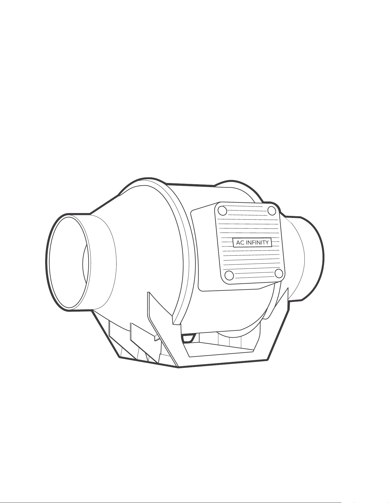
CLOUDLINE
MIXED FLOW INLINE FAN SYSTEMS
CLOUDLINE A4 shown
27
CLOUDLINE
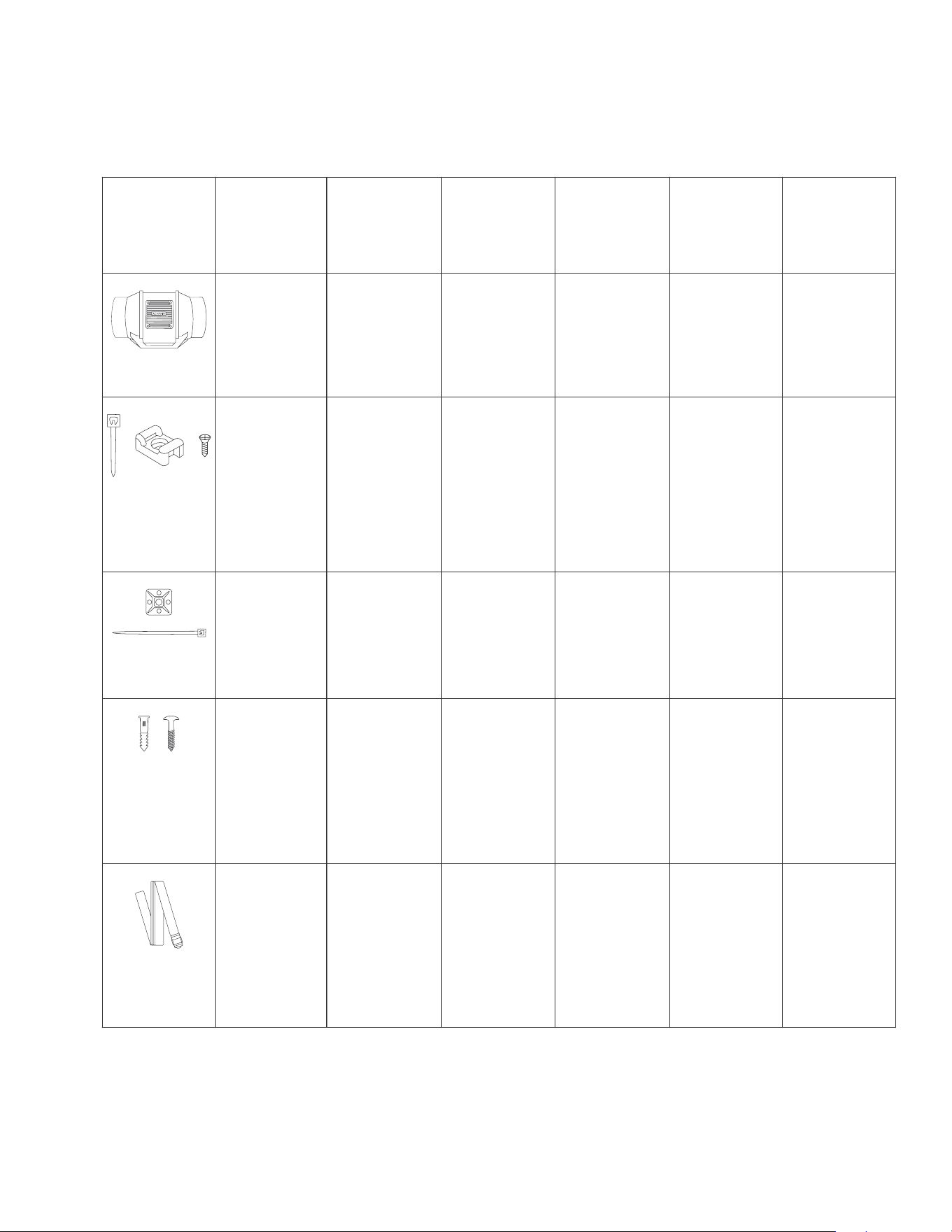
PRODUCT CONTENTS
Advance Grow
Tent Kit (2x2)
COMPACT
AC-PKA22
Advance Grow
Tent Kit (2x2)
AC-PKB22
Advance Grow
Tent Kit (2x4)
AC-PKB24
Advance Grow
Tent Kit (3x3)
AC-PKB33
Advance Grow
Tent Kit (4x4)
AC-PKB44
Advance Grow
Tent Kit (5x5)
AC-PKB55
CLOUDLINE A4
Inline Fan 4 in.
x1
CLOUDLINE A4
Inline Fan 4 in.
x1
CLOUDLINE A6
Inline Fan 6 in.
x1
CLOUDLINE A6
Inline Fan 6 in.
x1
CLOUDLINE A6
Inline Fan 6 in.
x1
INLINE FAN
CLOUDLINE PRO T6
Inline Fan 6 in.
x1
x6 x6 x6 x6 x6
WIRE TIE WITH
MOUNTING
BASE AND
SCREW
x6
x1 x1 x1 x1 x1
WIRE TIE WITH
3M BASE
x1
x4 x4 x4 x4 x4
DUCT FAN
MOUNTING
SCREW WITH
PLASTIC
ANCHOR
x4
x2 x2 x2 x2 x2
NYLON
HANGING
STRAPS
x2
28
CLOUDLINE
MOUNTING
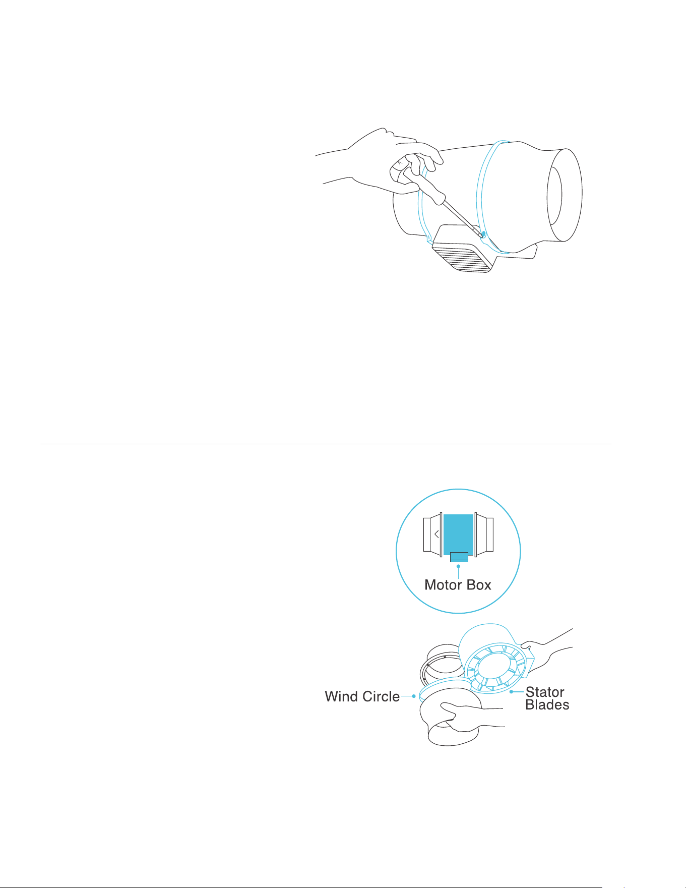
STEP 2
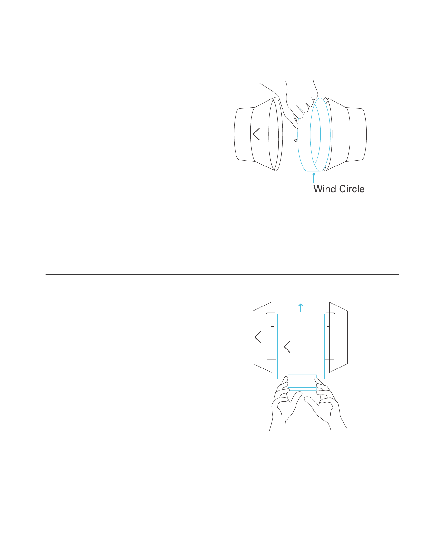
Remove the motor box from the flange
bracket. Remove the wind circle between
the motor box and the intake flange.
STEP 1
Unscrew the bolts on both sides from the
plastic rings using a Phillips screwdriver.
Pliers are also required for removing the
metal rings of the CLOUDLINE PRO T6.
29
CLOUDLINE
MOUNTING
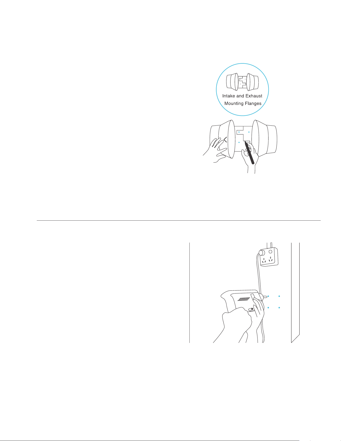
STEP 3
Use the flange bracket to set your
desired fan position. Mark the four
mounting holes.
STEP 4
Drill four holes into the marked locations.
Make sure your mounting area is
structurally sound and free from obstruction.
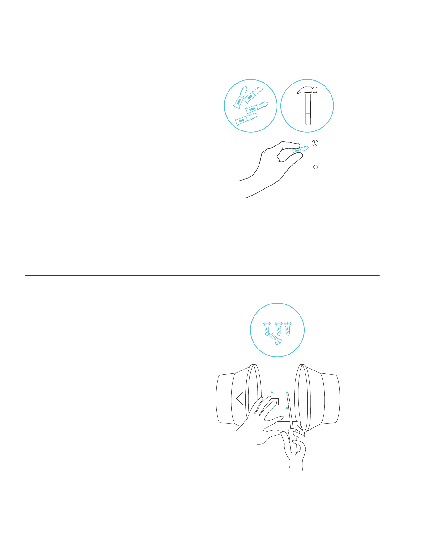
30
CLOUDLINE
MOUNTING
STEP 5
If you are mounting onto anything other
than a wood support or stud, insert the
included four wall anchors into the drilled
mounting holes.
You may need to use a hammer to secure
them through the holes.
STEP 6
Align the flange bracket’s holes with the
wall anchors. Screw in four wood screws
with a screwdriver or drill to secure the
flange bracket.
Make sure its airflow arrow is pointing in
your desired direction.
31
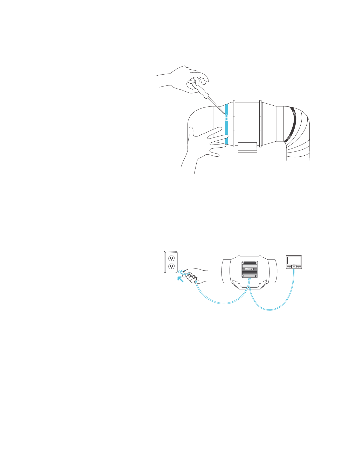
STEP 8
Slide the motor box back into the flange
bracket, making sure its airflow arrow
is pointing in the same direction as the
flange bracket’s arrow.
For the CLOUDLINE A-series fans, crew
the bolts back into the plastic rings to
secure the motor box to the flange bracket.
For the CLOUDLINE PRO T6, tighten the
metal clamps using a Phillips screwdriver
and pliers to secure the motor box.
STEP 7
Place the wind circle back into the
intake flange.
Reposition the metal clamps over the
flanges for the CLOUDLINE PRO T6.
CLOUDLINE
MOUNTING
32
STEP 9
If installing ducting, use the included duct
clamps to secure it to either end of the
duct fan, making sure there is a tight seal.
Tighten the duct clamps using a
flathead screwdriver.
CLOUDLINE
MOUNTING
POWERING AND SETUP
Plug the fan’s power cord into an AC
power outlet to power it and the controller.
Refer to pages 80-83 for controller
installation instructions.
33
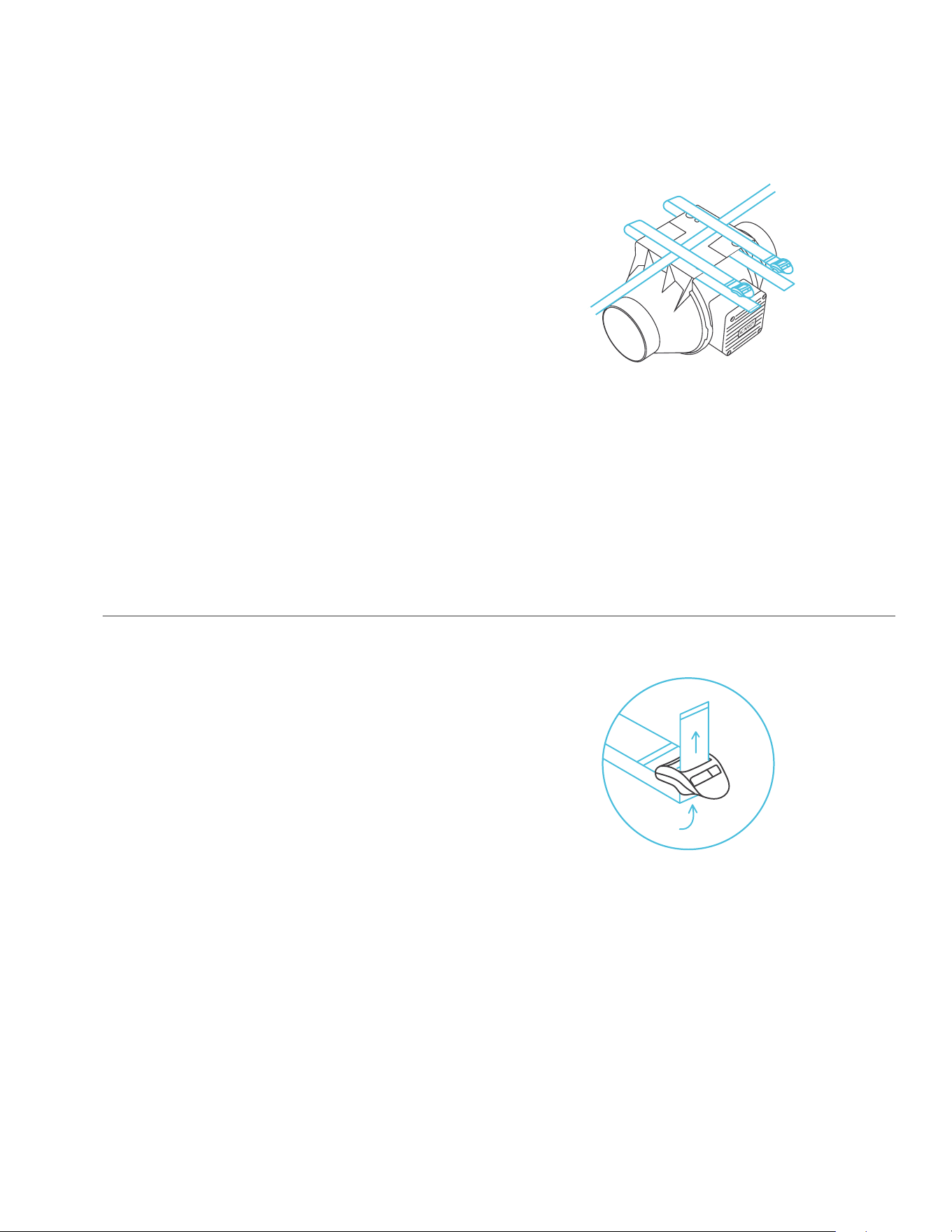
STEP 1
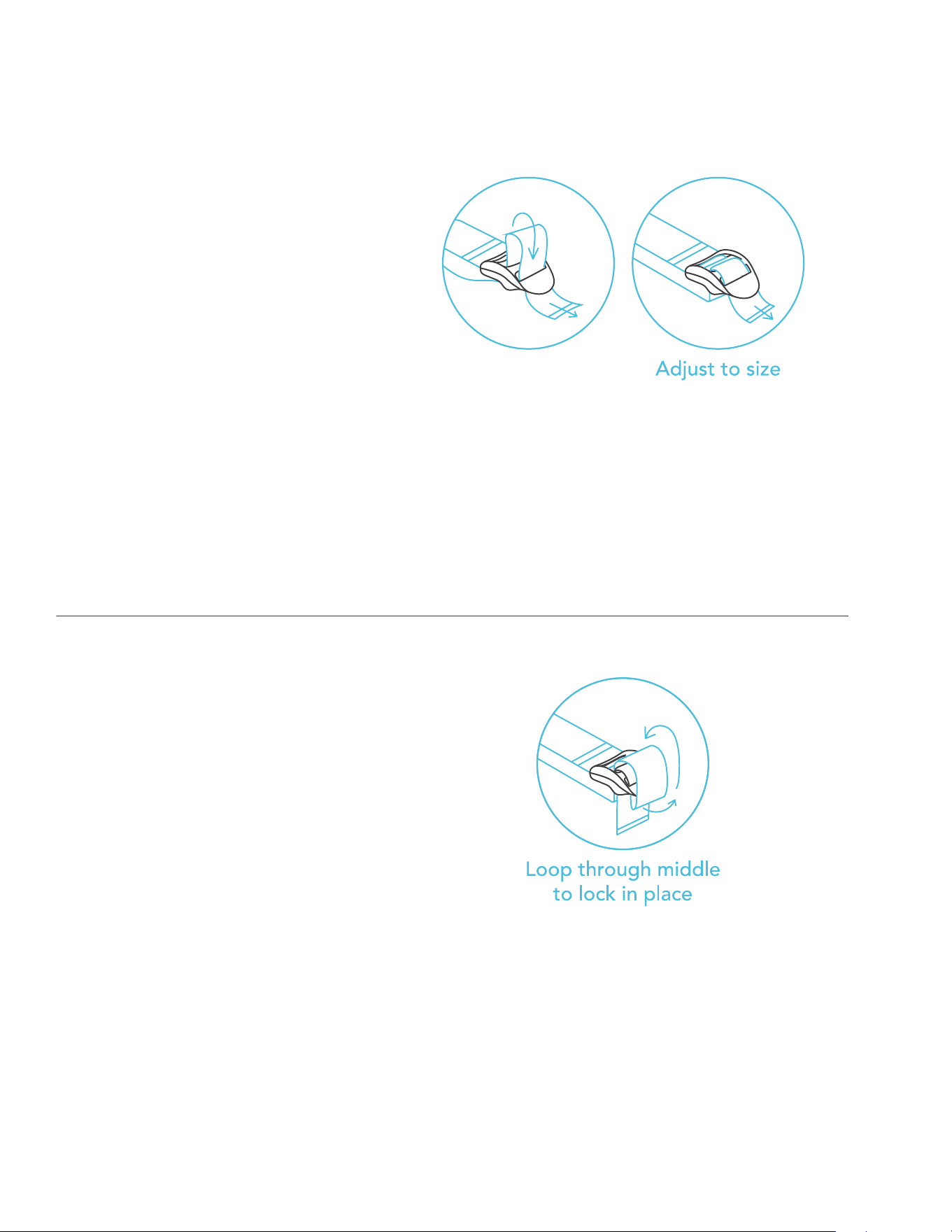
Loop the strap around the bracket and a pole.
STEP 2
Slip the strap through the inner ladder lock
slot from the bottom.
CLOUDLINE
OVERHEAD HANGING
34
STEP 3
Route the strap into the outer ladder lock
slot from the top. Adjust the length of the
completed loop as needed.
STEP 4
Tuck the loose end through the center
gap of the ladder lock to secure the loop.
CLOUDLINE
OVERHEAD HANGING
35
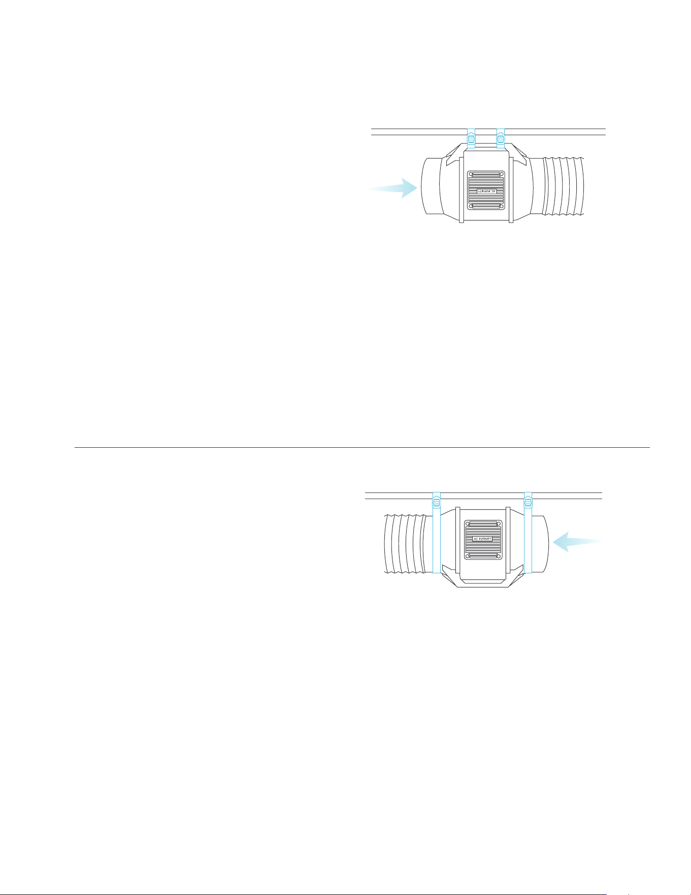
STEP 5(b) - Hanging Upward
To hang the fan right-side up, loop and
tighten the straps, as shown in steps 1-4,
around the pole.
Hang the fan by the duct flanges to
secure it.
STEP 5(a) - Hanging Downward
Let the fan hang by the pole once the
straps are secure.
Make sure the fan's airflow arrow is
pointing towards your desired direction.
CLOUDLINE
OVERHEAD HANGING
36
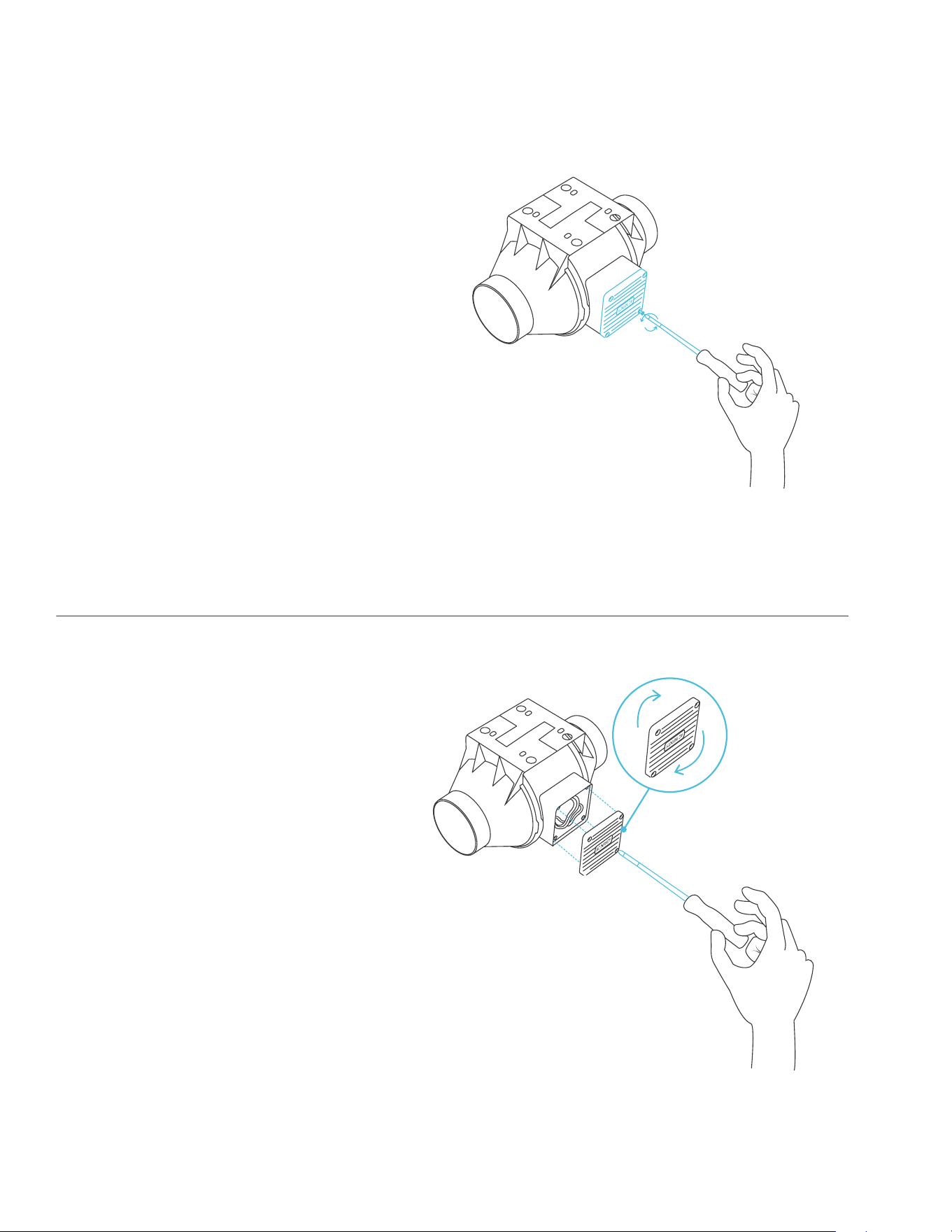
STEP 1
Unscrew the motor cap using a screwdriver.
STEP 2
Rotate the motor cap to your desired
orientation. Reapply the screws.
Rotating the motor cap will not void your warranty.
CLOUDLINE
MOTOR CAP
37
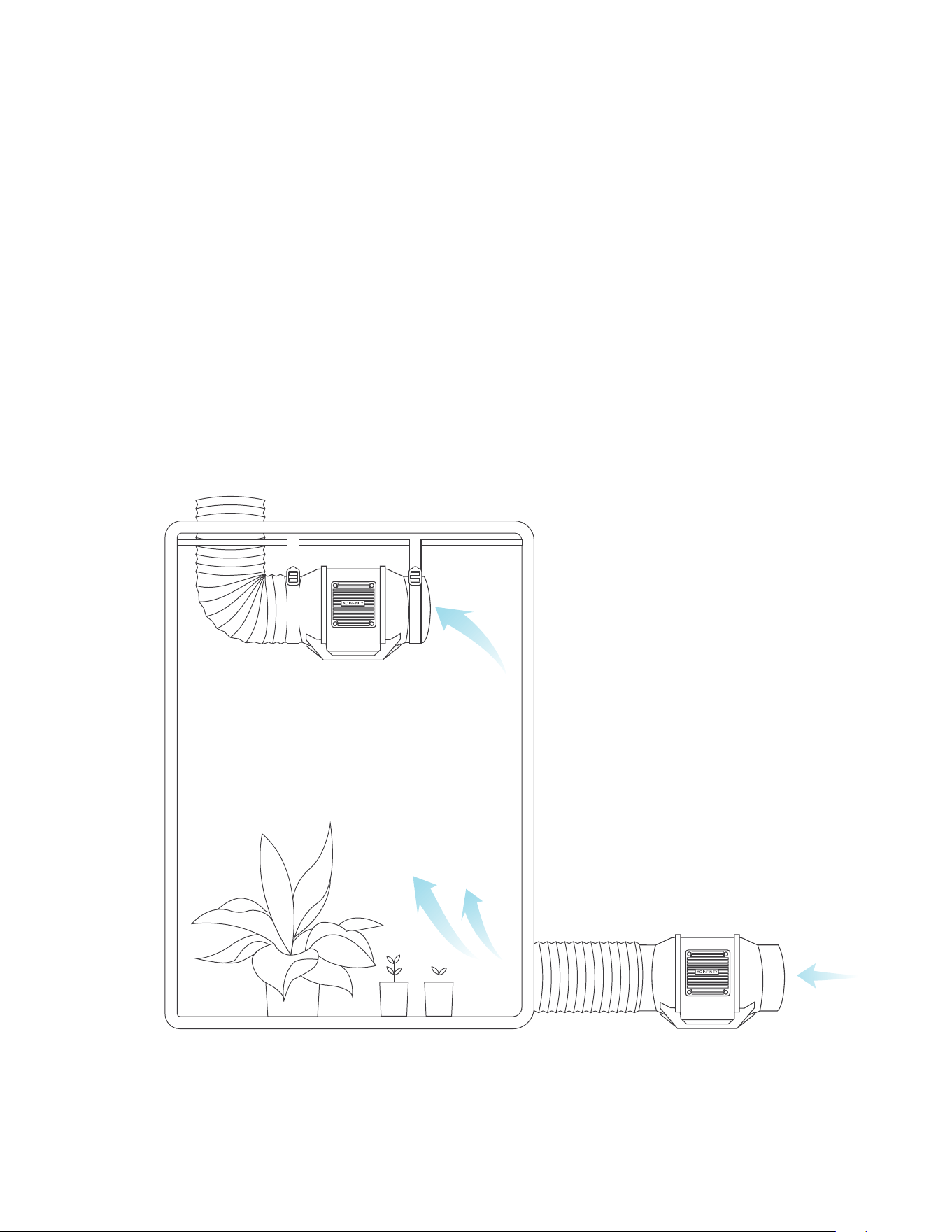
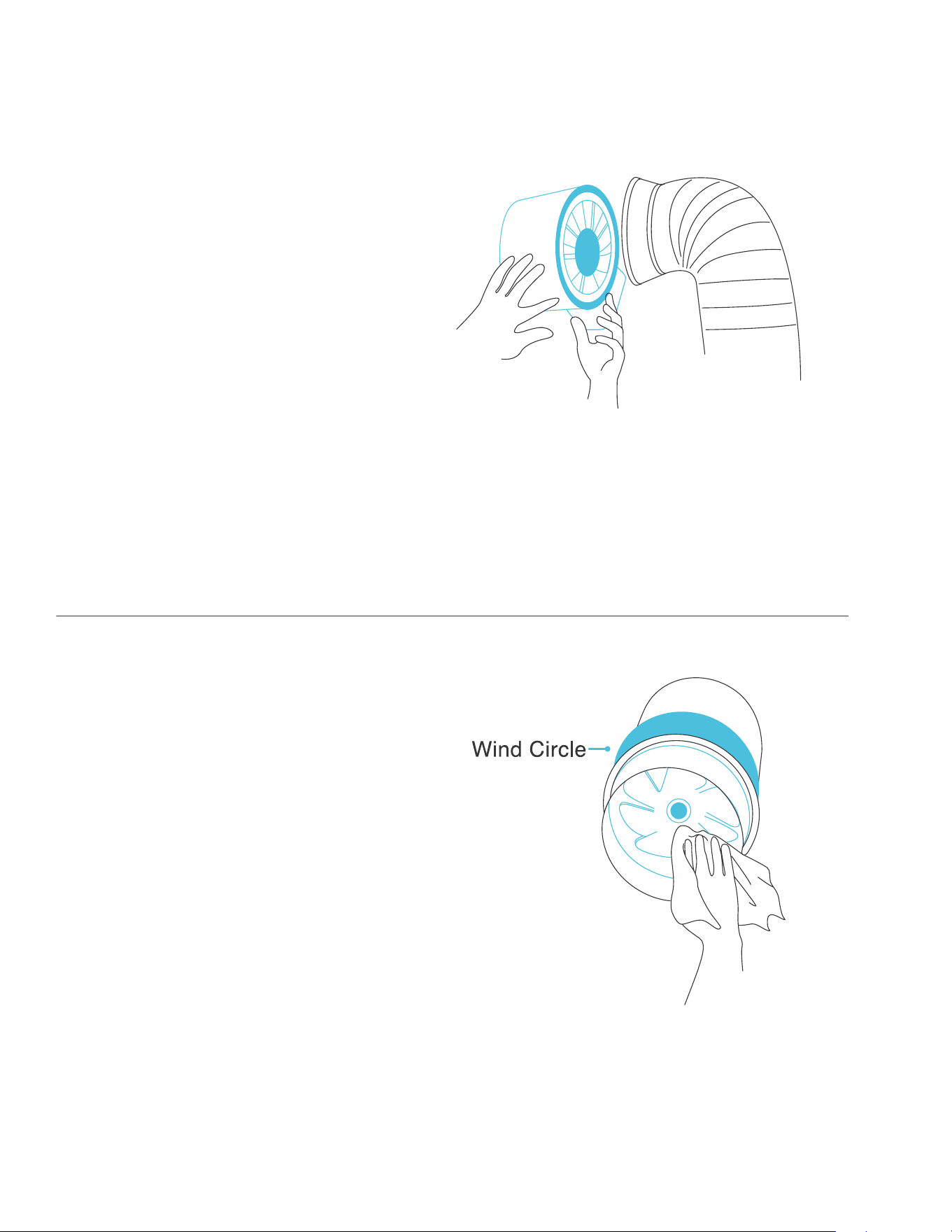
INTAKE AND EXHAUST
This fan can be used as either an intake fan or an exhaust fan in grow rooms and larger grow
tents. To achieve optimal whole space ventilation, the intake fan or opening —if not using a fan—
must be situated at a bottom corner of your grow space. The exhaust fan must be hung (shown
below) or mounted at the highest opposite corner possible.
Make sure the intake fan’s airflow arrow is pointing towards your grow space and the exhaust
fan’s arrow points away from your grow space.
CLOUDLINE
CONFIGURATION SETUP
38
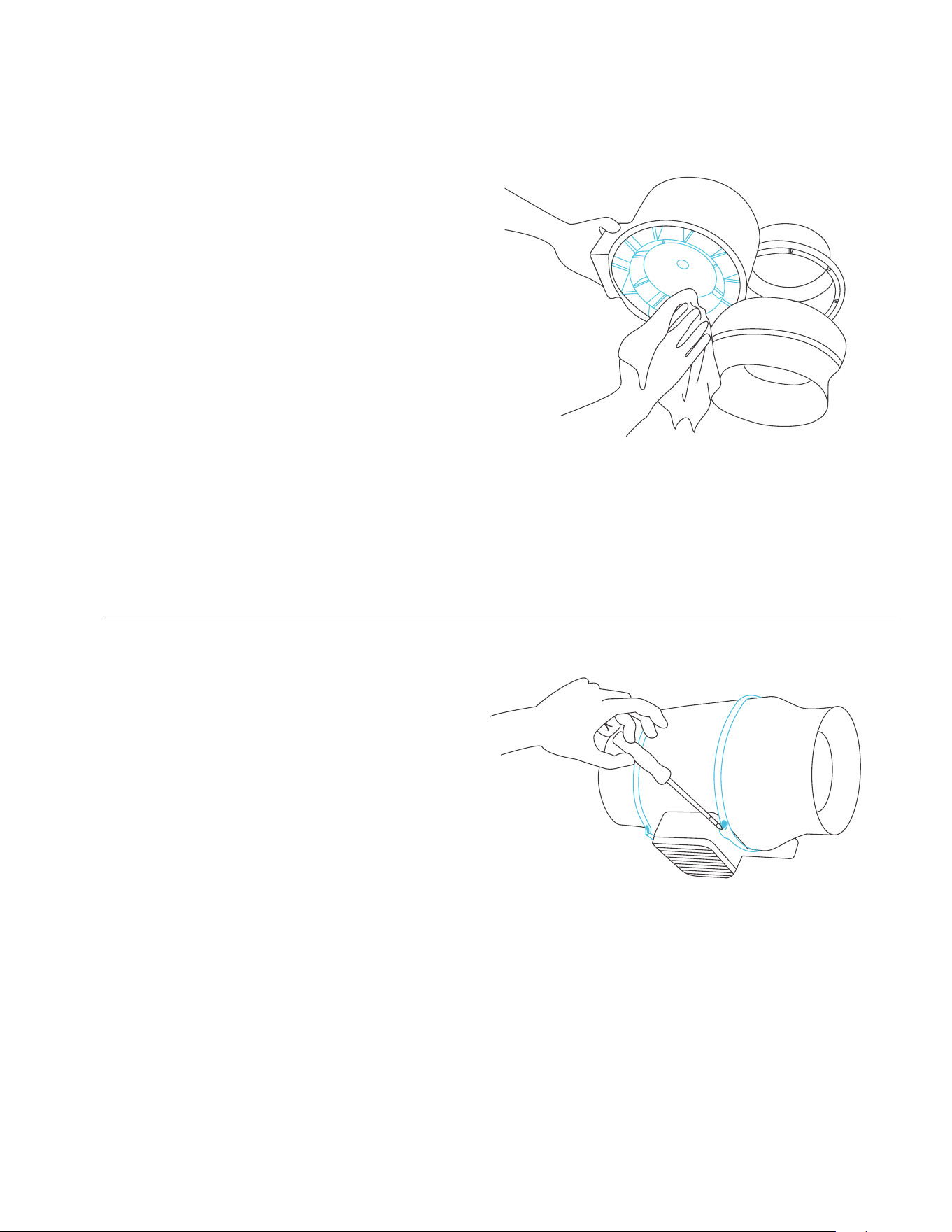
STEP 1
Remove the motor box from the mounting
flange. Refer to steps 1-2 on page 28 to
learn how to remove the motor box.
STEP 2
Use a damp cloth to clear the impeller and
fan blades of any dust and debris. Remove
the wind circle in between the motor box
and input flange.
CLOUDLINE
CLEANING
39
CLOUDLINE
CLEANING
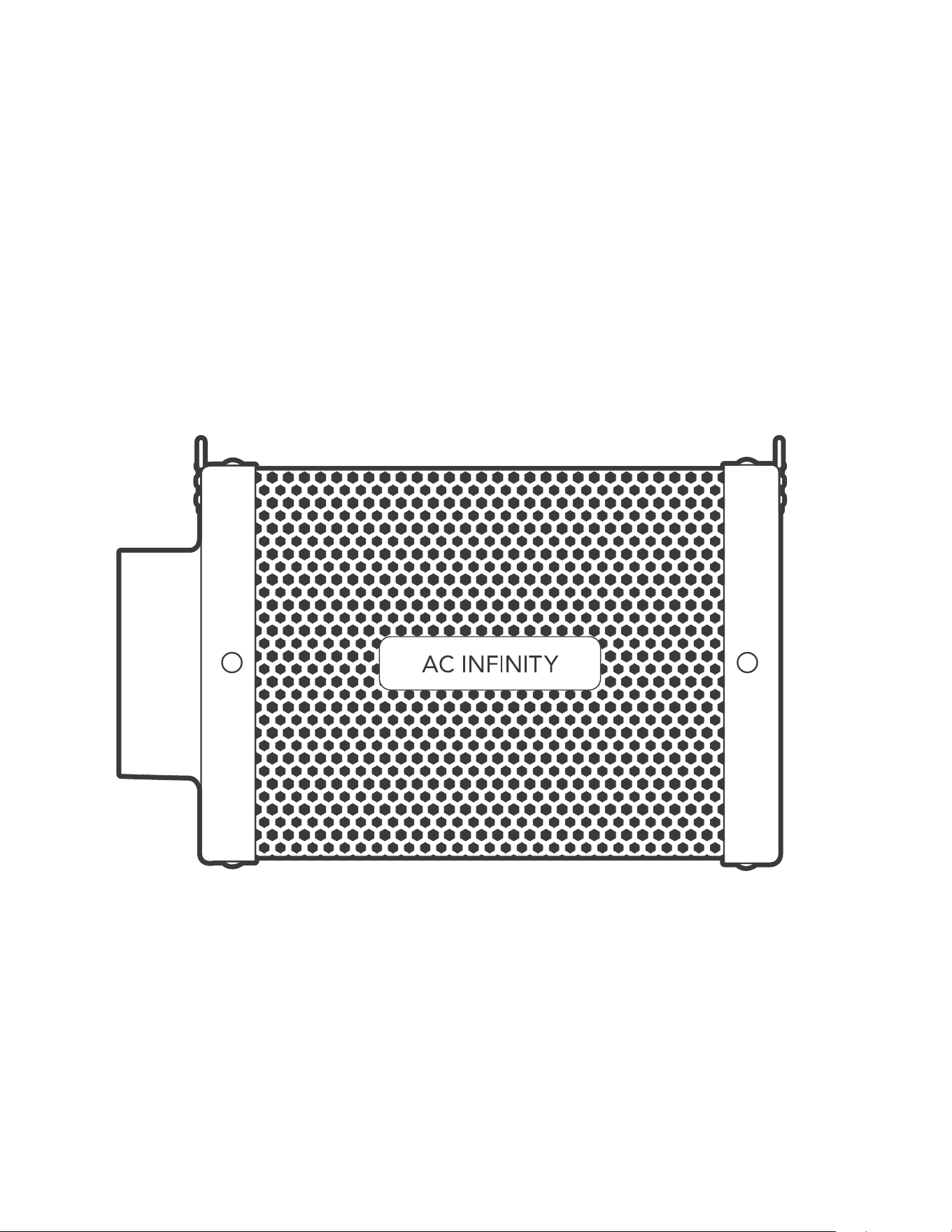
STEP 4
Secure the motor box onto the mounting
flanges. Refer to steps 7-9 on pages 31-32
to learn how to secure the motor box.
STEP 3
Clear the stator blades of any dust and
debris on the opposite end. Clean the area
inside the output and exhaust flanges.
40
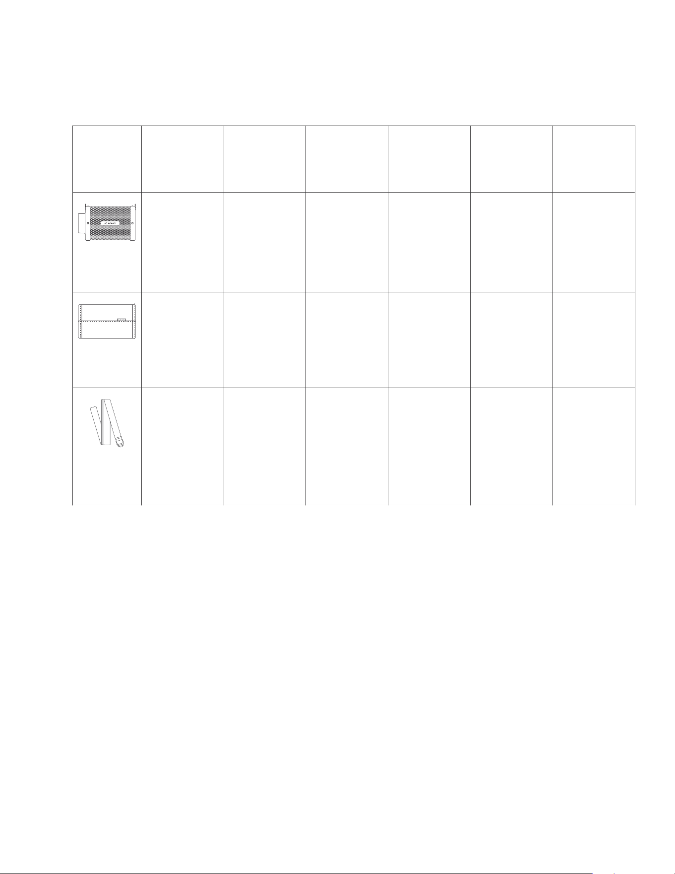
DUCT CARBON FILTER
PREMIUM AUSTRALIAN CHARCOAL
41
CARBON FILTER
PRODUCT CONTENTS
Advance Grow
Tent Kit (2x2)
COMPACT
AC-PKA22
Inline Carbon
Filter, 4 in.
x1
4 in.
x2
x2
Advance Grow
Tent Kit (2x2)
AC-PKB22
Inline Carbon
Filter, 4 in.
x1
4 in.
x2
x2
Advance Grow
Tent Kit (2x4)
AC-PKB24
Inline Carbon
Filter, 6 in.
x1
6 in.
x2
x2
Advance Grow
Tent Kit (3x3)
AC-PKB33
Inline Carbon
Filter, 6 in.
x1
6 in.
x2
x2
Advance Grow
Tent Kit (4x4)
AC-PKB44
Inline Carbon
Filter, 6 in.
x1
6 in.
x2
x2
CARBON
FILTER
PREFILTER
CLOTH
NYLON
HANGING
STRAPS
Advance Grow
Tent Kit (5x5)
AC-PKB55
Inline Carbon
Filter, 6 in.
x1
6 in.
x2
x2
42
CARBON FILTER
INSTALLATION
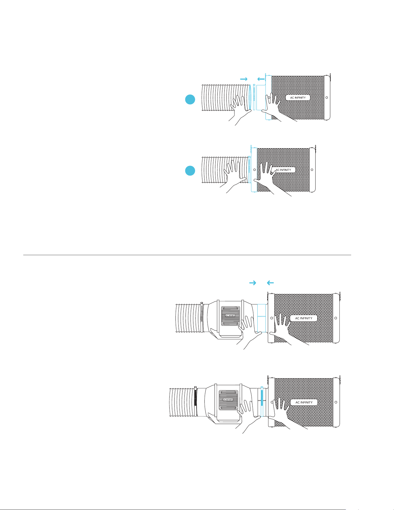
STEP 1
Connect your duct tube over your
filter. Use duct clamps to secure the
connection. You may also apply ducting
tape before using the duct clamps for
even further security.
STEP 2
You may also connect your filter directly
to your inline duct fan. Use ducting tape
to secure them together.
If your filter is placed in a humid space,
position it at the highest point possible.
2
1
43
CARBON FILTER
OVERHEAD HANGING (STRAPS)
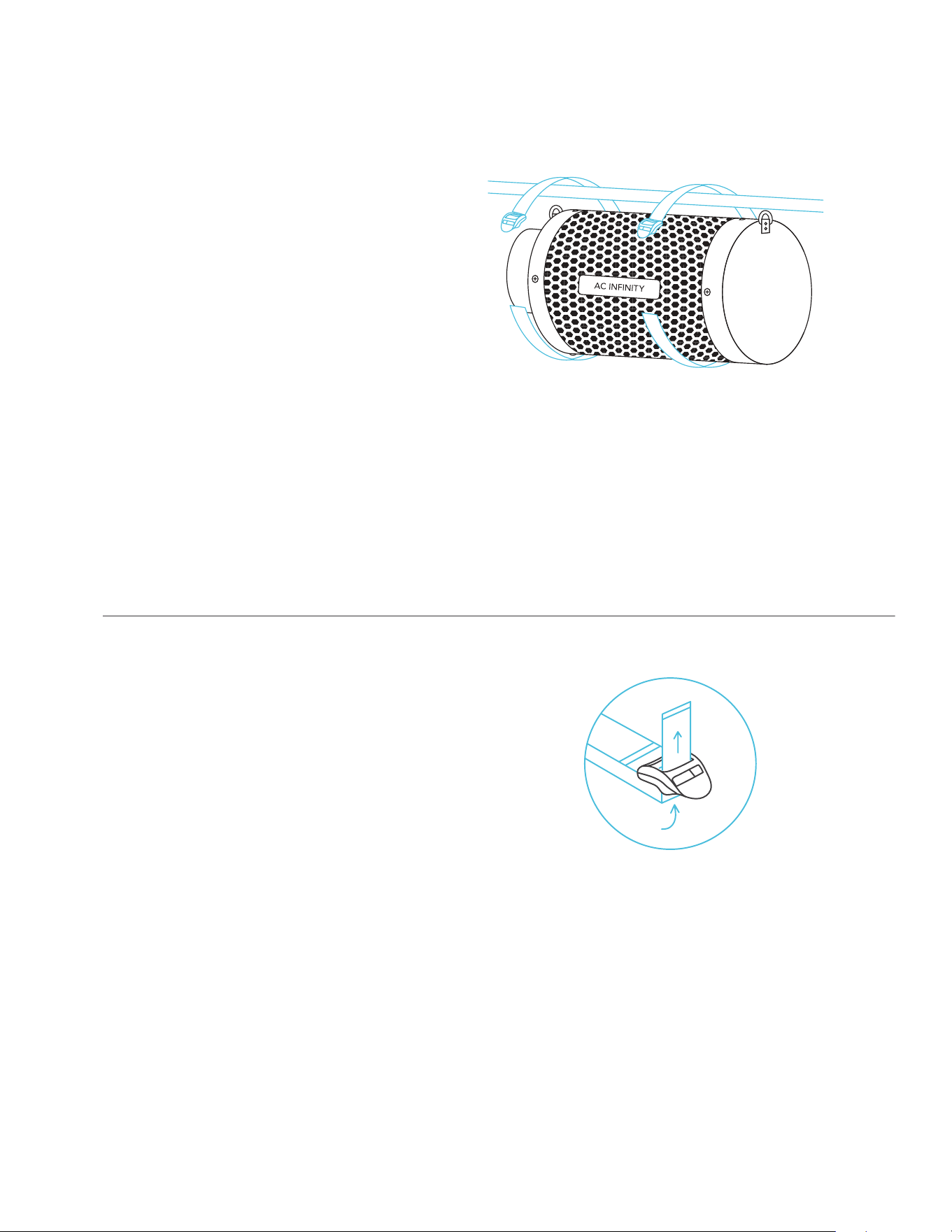
STEP 1
Loop the strap around a hanging pole.
STEP 2
Slip the strap through the inner ladder
lock slot from the bottom.
44
CARBON FILTER
OVERHEAD HANGING (STRAPS)
STEP 3
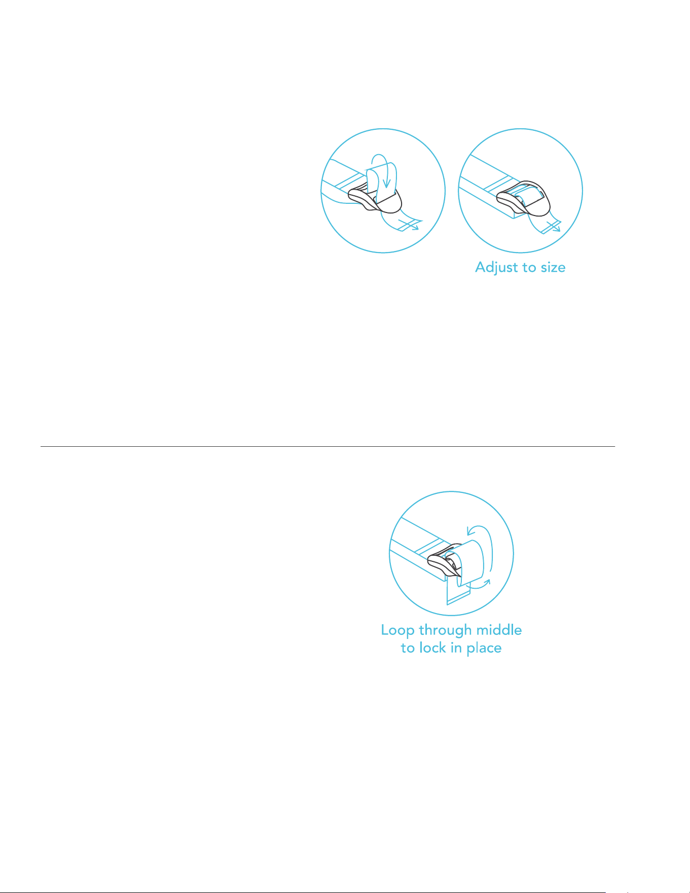
Route the strap into the outer ladder lock
slot from the top. Adjust the length of the
completed loop as needed.
STEP 4
Tuck the loose ends through the center
gap of the ladder lock to secure the loop.
45
CARBON FILTER
OVERHEAD HANGING (STRAPS)
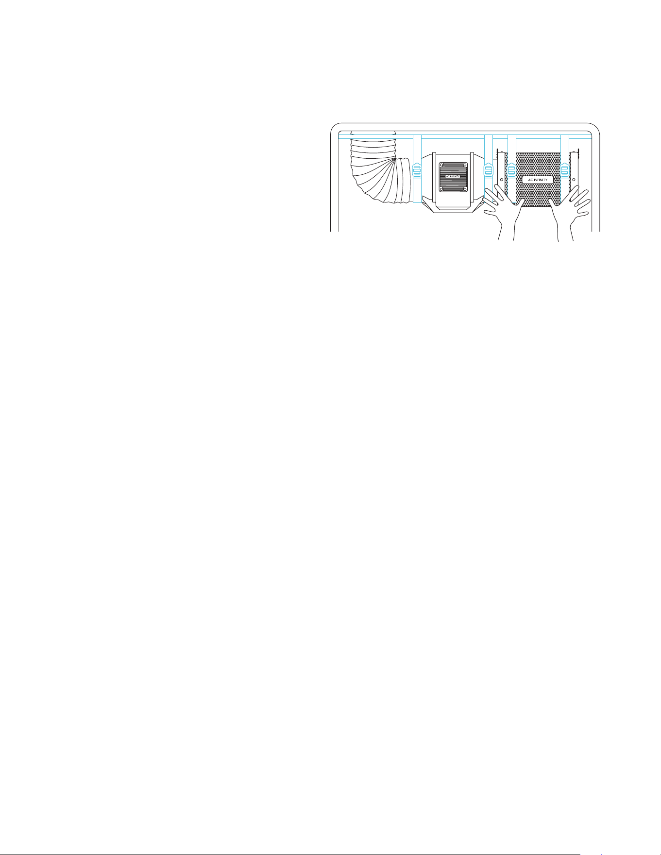
STEP 5
Connect your filter to your ductwork
using your preferred method, as shown
on page 42.
46
CARBON FILTER
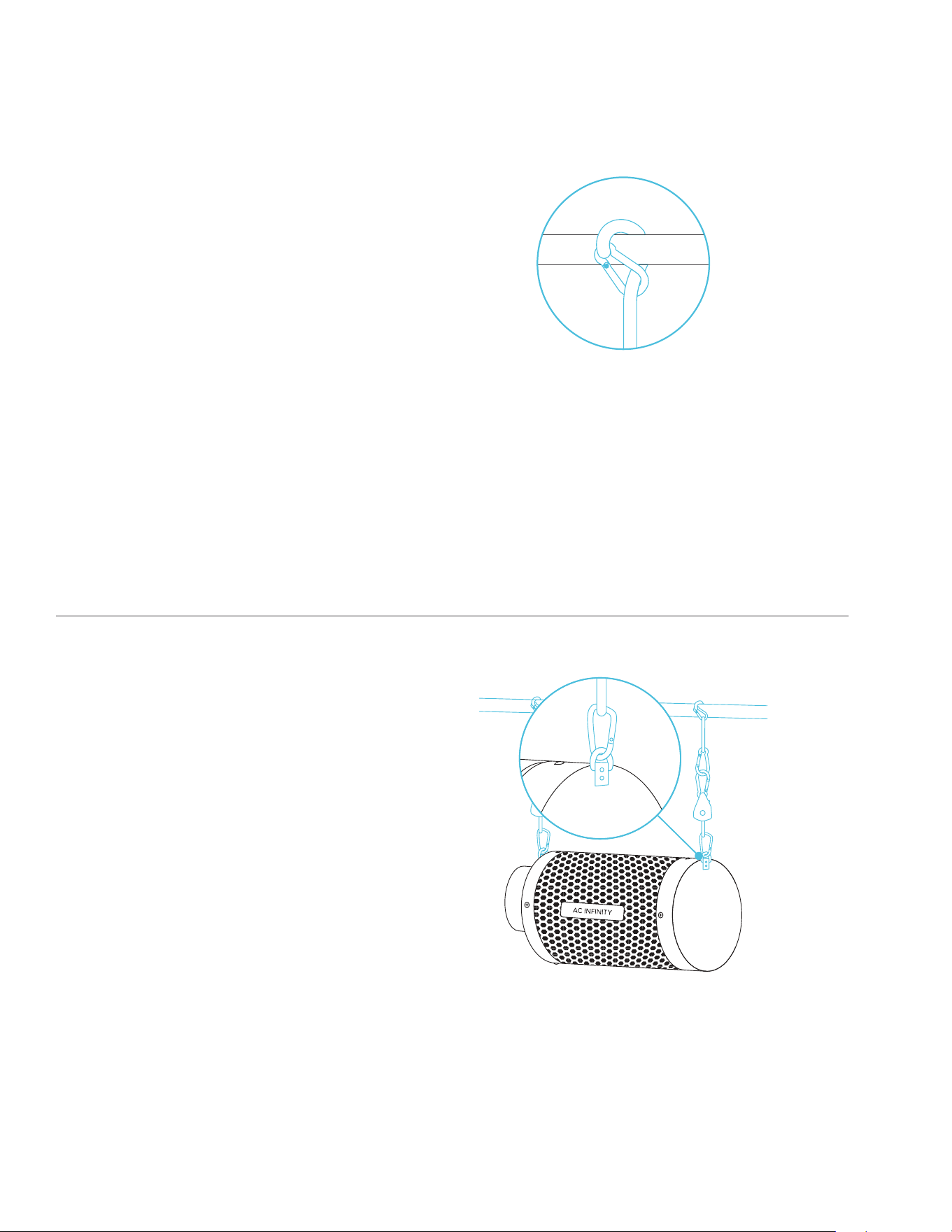
OVERHEAD HANGING (ROPE CLIPS)*
STEP 1
Loop the rope clip hangers around your
grow tent’s support beams.
STEP 2
Hook the carabiners into the steel hooks
located on the flanges.
*Sold separately
47
CARBON FILTER
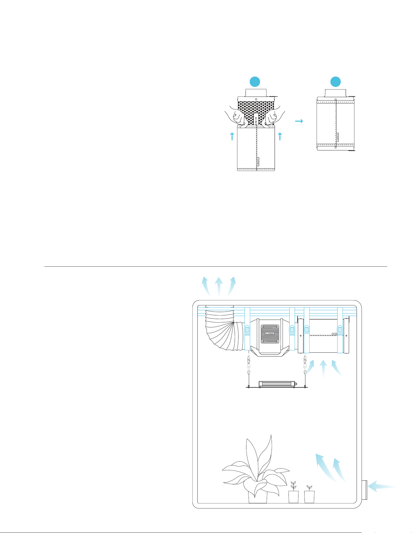
CONFIGURATION SETUP
INTERIOR HANGING
To use this filter in intake
applications, place the filter
inside your grow space. Make
sure your filter is connected to
your inline duct fan's intake end
before completing the installation.
PREFILTER
When placing your filter inside your
grow space, slip the cloth over your filter
to block dust and other particles from
passing through.
Make sure the entire metal mesh is
covered by the cloth.
21
48
CARBON FILTER
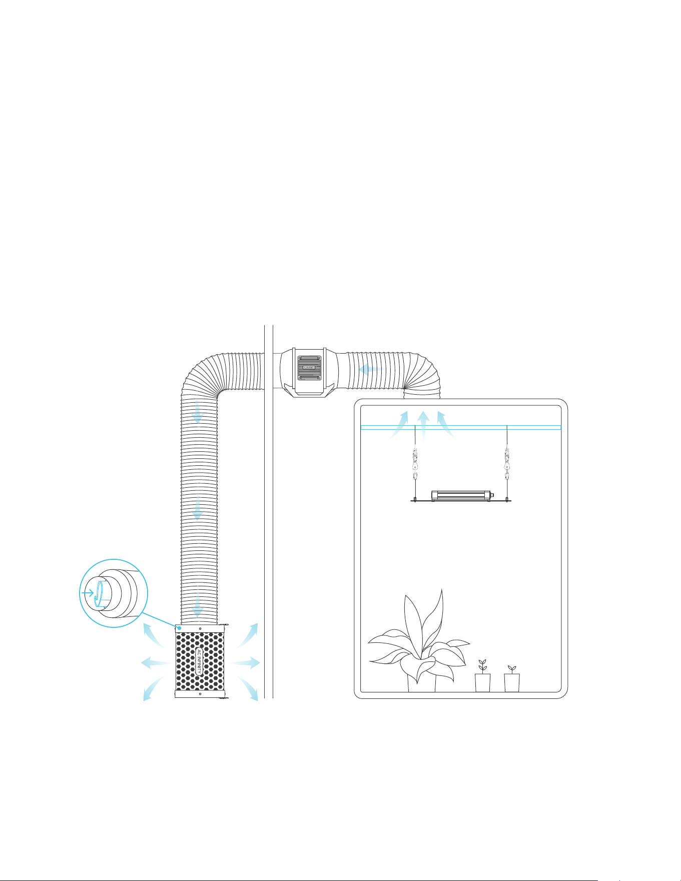
CONFIGURATION SETUP
EXTERIOR MOUNTING
To use this filter in exhaust applications, place the filter outside of your grow space. Make sure
your filter is connected to your inline duct fan's exhaust end before completing the installation.
Stuff the prefilter inside of the filter to lengthen the carbon bed's lifespan.
49
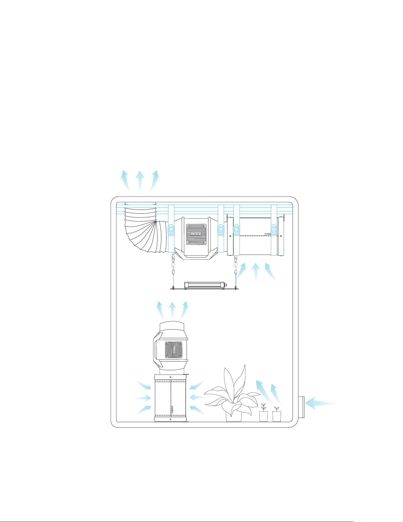
OVERSIZED GROW SPACE
Use a dual fan and filter combination inside your grow space to completely scrub away odor in
larger grow rooms and tents. Set the secondary filter on the floor and the inline fan on top of it
so that the exhaust end points up.
CARBON FILTER
CONFIGURATION SETUP
50
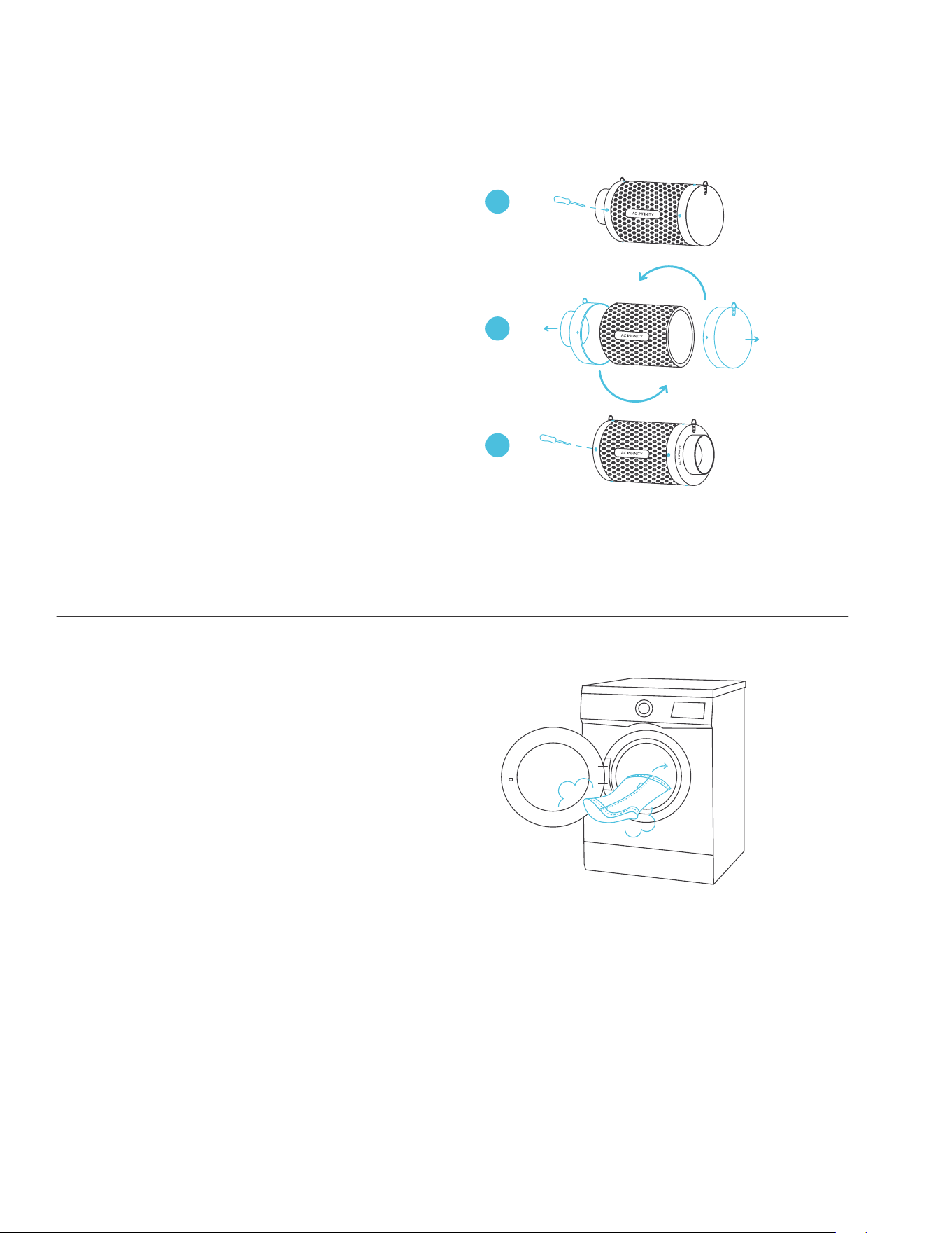
REVERSING THE FLANGES
To extend the filter's lifespan and utilize
its entire carbon bed, rotate the flanges
from either end.
Remove the screws from the flanges
to release them from the filter. Replace
the flanges on the other ends and screw
them back into place.
WASHING THE PREFILTER
Wash the reusable cloth as needed to
clear it of any dust and build-up. This will
further extend the lifespan of the filter.
1
2
3
CARBON FILTER
MAINTENANCE

51
52
IONBOARD / IONFRAME EVO
GROW LIGHT SYSTEM
IONBOARD S22 shown
53
GROW LIGHT SYSTEM
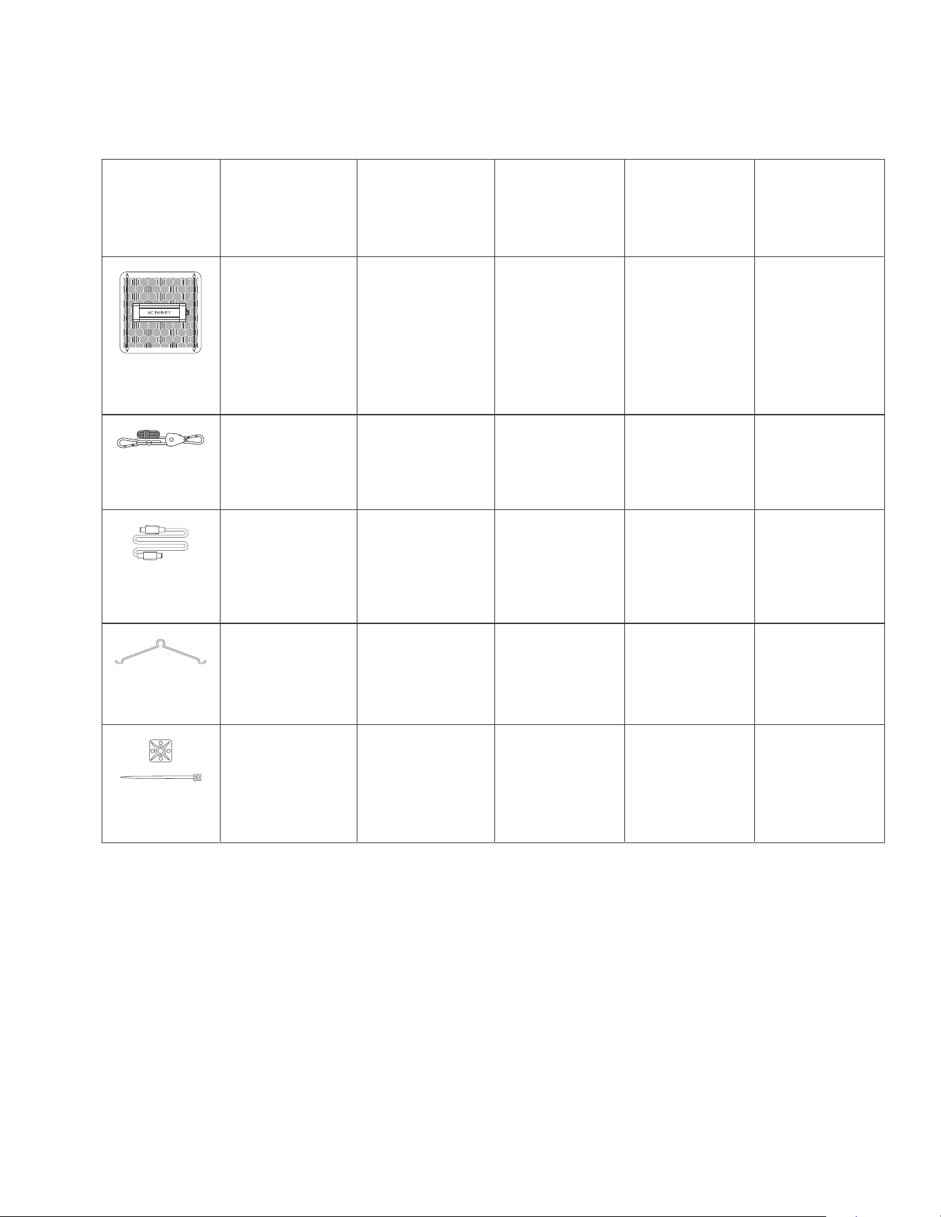
PRODUCT CONTENTS: IONBOARD
LED GROW
LIGHT
ROPE CLIP
HANGERS
HANGING
HOOK
CONTROLLER
CORD
IONBOARD S22,
2x2 Coverage
x1
IONBOARD S22,
2x2 Coverage
x1
IONBOARD S24,
2x4 Coverage
x1
IONBOARD S33,
3x3 Coverage
x1
IONBOARD S44,
4x4 Coverage
x1
x2 x2 x2 x2 x2
UIS Male-Male
Controller Cord
x1
UIS Male-Male
Controller Cord
x1
UIS Male-Male
Controller Cord
x1
UIS Male-Male
Controller Cord
x1
UIS Male-Male
Controller Cord
x1
x2 x2 x2 x2 x2
Advance Grow
Tent Kit (2x2)
COMPACT
AC-PKA22
Advance Grow
Tent Kit (2x2)
AC-PKB22
Advance Grow
Tent Kit (3x3)
AC-PKB33
Advance Grow
Tent Kit (2x4)
AC-PKB24
Advance Grow
Tent Kit (4x4)
AC-PKB44
WIRE TIE WITH
3M BASE
x1 x1 x1 x1 x1
54
GROW LIGHT SYSTEM
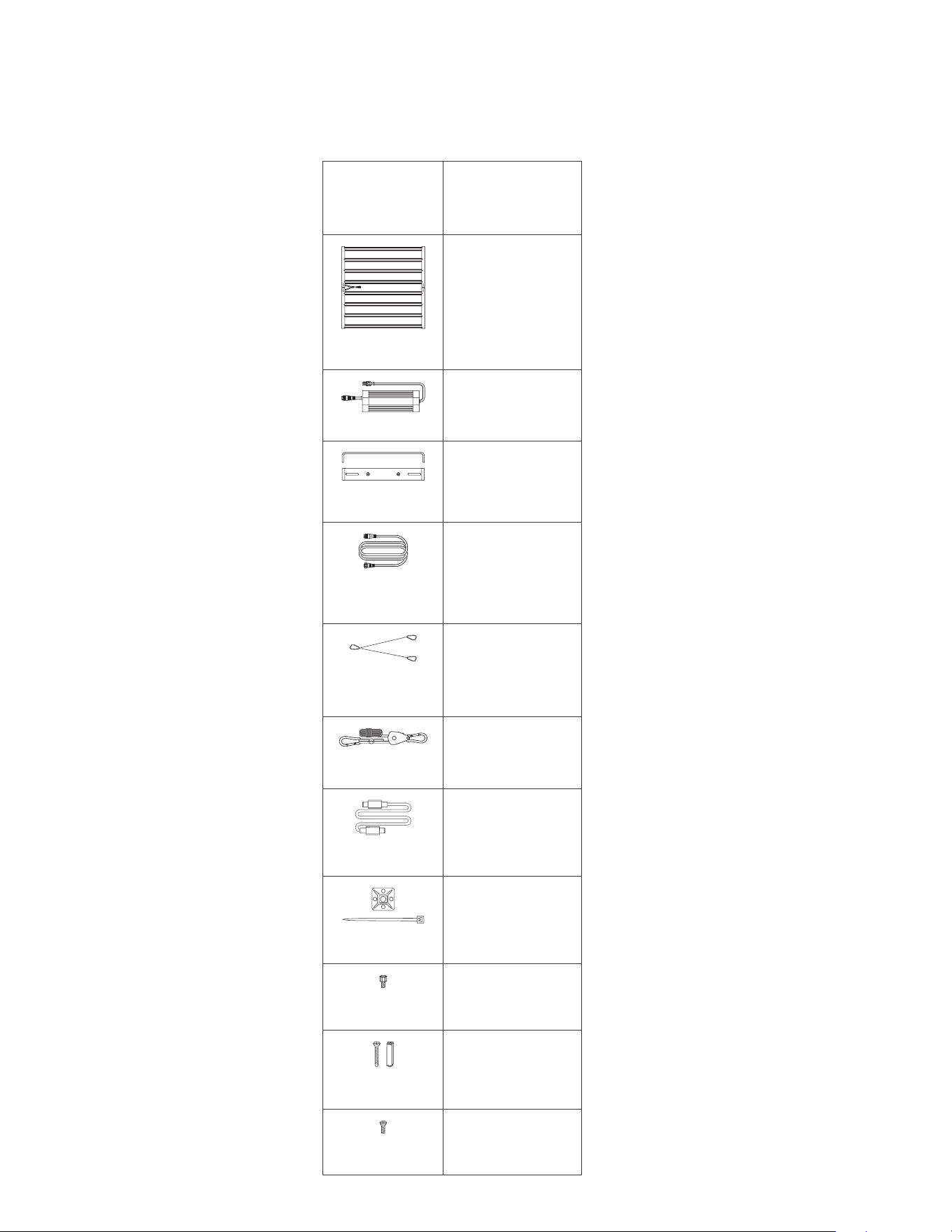
PRODUCT CONTENTS: IONFRAME EVO
ROPE CLIP
HANGERS
CONTROLLER
CORD
WIRE TIE WITH
3M BASE
LED GROW
LIGHT
LED DRIVER
DRIVER
BRACKETS
DRIVER
EXTENSION
CORD
STAINLESS
STEEL WIRE
HANGERS
NYLON
SCREWS
WOOD
SCREWS
DRIVER SCREWS
(BRACKET MOUNT)
Advance Grow
Tent Kit (5x5)
AC-PKB55
IONFRAME EVO8,
5x5 Coverage
x1
x1
x2
x1
x2
x2
x1
x6
x4
x4
UIS Male-Male
Controller Cord
x1
55
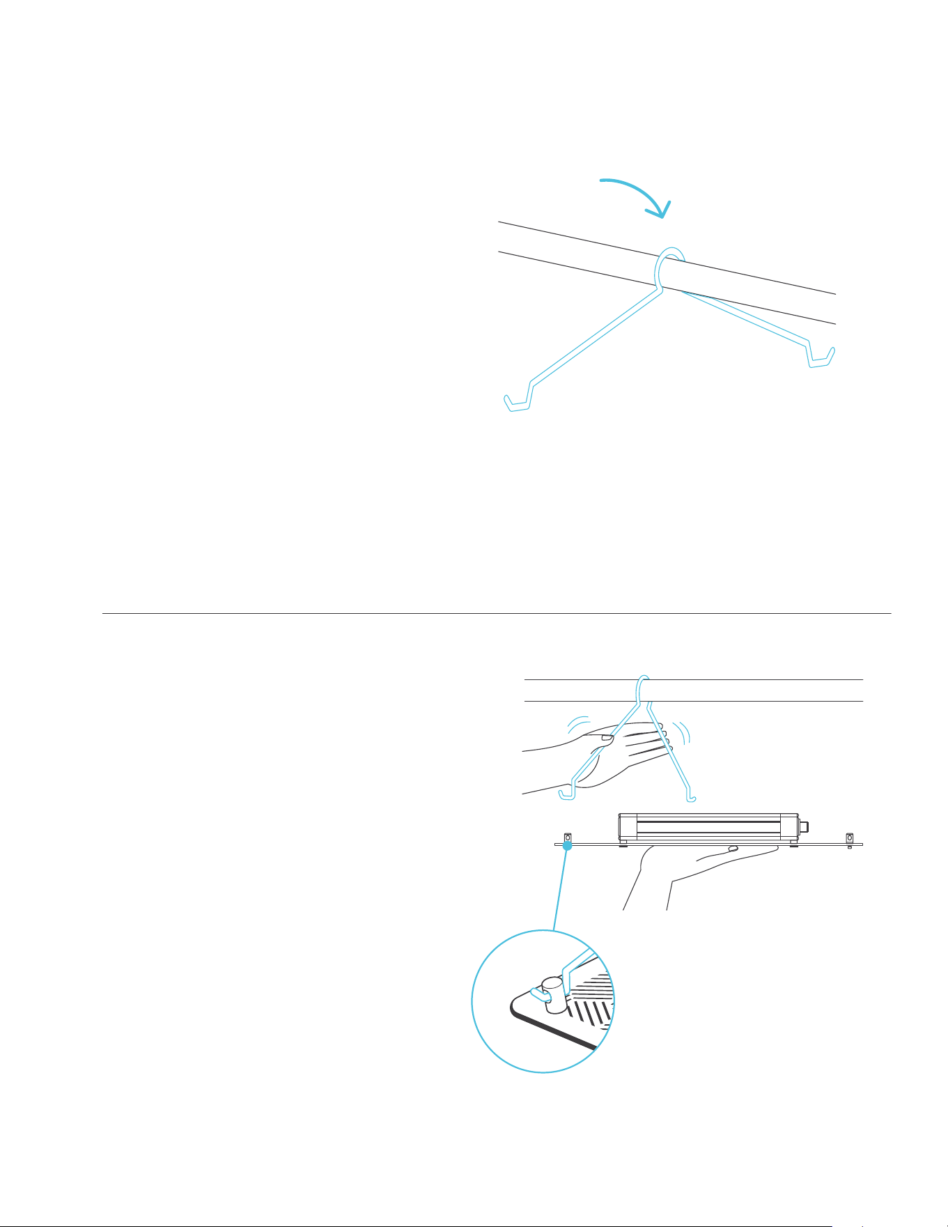
STEP 1
Hang the steel hooks over your grow
tent’s support beams.
STEP 2
While supporting your grow light, bend
the steel hooks to insert the ends into the
slotted holes of the end caps.
Repeat this step on the other side of your
grow light.
GROW LIGHT SYSTEM
INSTALLATION: IONBOARD S22 / S24
56
GROW LIGHT SYSTEM
INSTALLATION: IONBOARD S33 / S44
STEP 1
Insert the steel hooks into your grow
light's slotted holes of the end caps.
STEP 2
Position your grow tent's pole under the
steel hooks. Install the pole onto your
grow tent's frame.
*Two people are recommended for this installation.
57
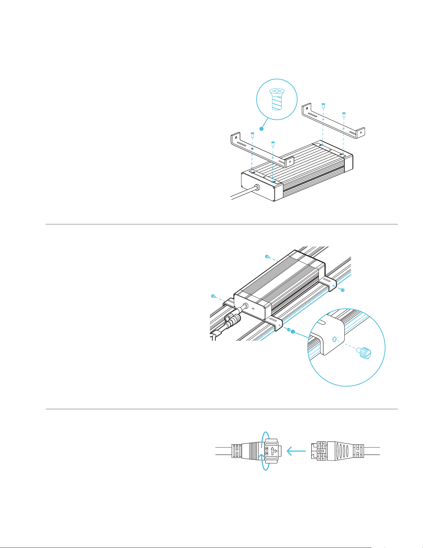
GROW LIGHT SYSTEM
DRIVER MOUNTING (FRAME): IONFRAME EVO
STEP 2
Flip the driver over and place it over the
two center columns of your grow light.
Secure the brackets to the columns by
screwing in the nylon screws using a
flathead screwdriver.
STEP 1
Align the brackets' mounting holes with
the driver's mounting points located on
the driver's underside, making sure the
brackets' legs are pointing up.
Secure the brackets by screwing in the
driver screws using a Phillips screwdriver.
STEP 3
Connect the driver socket to the grow
light connector. This will lock the
connection in place.
Twist the lock and pull the connector out
to disconnect it from the driver's socket.
58
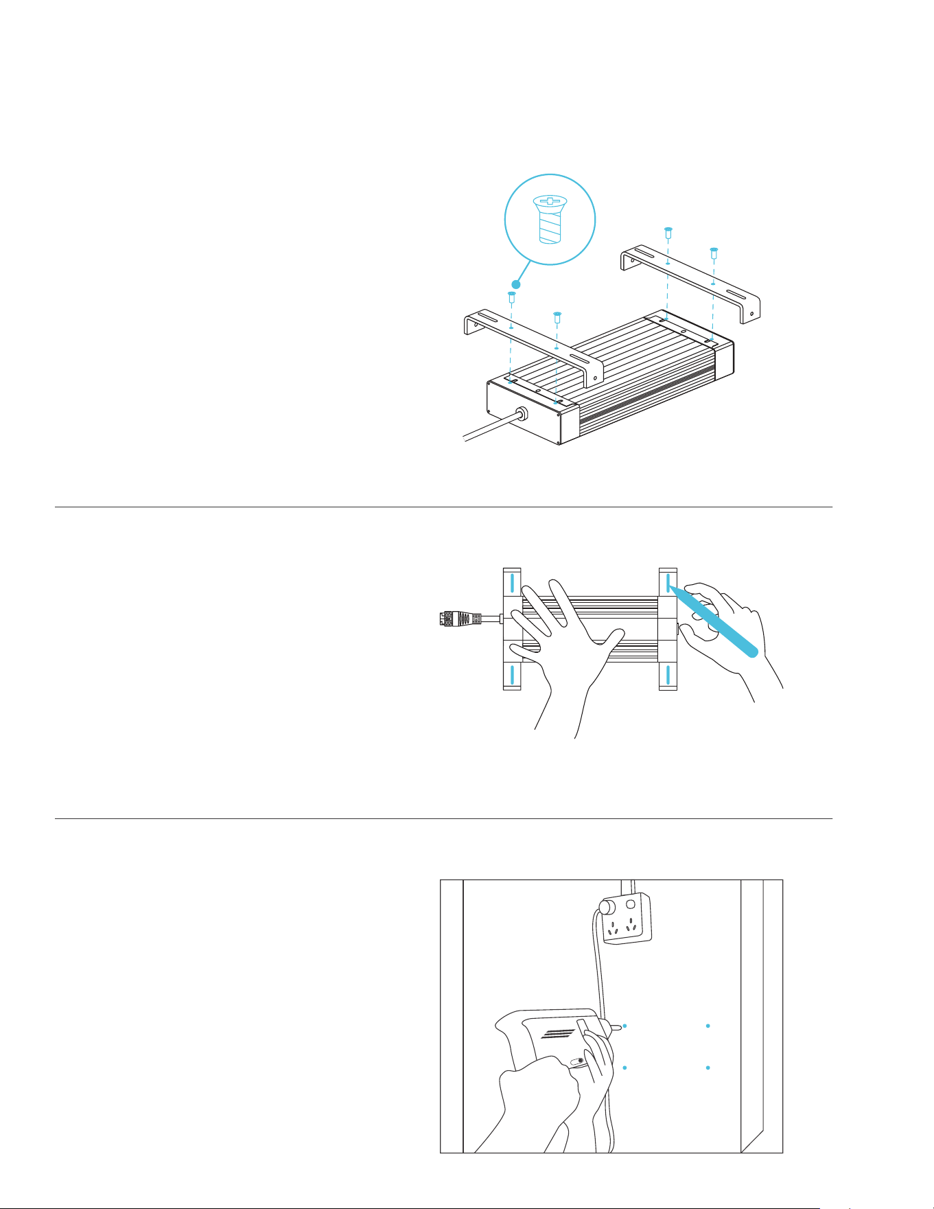
DRIVER MOUNTING (WALL): IONFRAME EVO
STEP 2
Mark your desired mounting position
using the brackets' mounting slots.
STEP 1
Align the brackets' mounting holes with
the driver's mounting points located on
the driver's underside, making sure the
brackets' legs are pointing down.
Secure the brackets by screwing in the
driver screws using a Phillips screwdriver.
STEP 3
Drill four holes into the marked
locations. Make sure your mounting
area is structurally sound and free from
obstruction.
GROW LIGHT SYSTEM
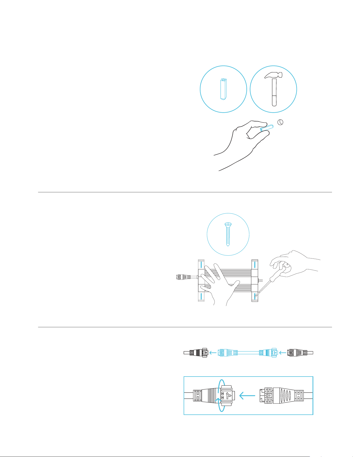
59
DRIVER MOUNTING (WALL): IONFRAME EVO
STEP 4
If you are mounting onto anything other
than a wood support or stud, insert the
included four wall anchors into the drilled
mounting holes.
You may need to use a hammer to
secure them through the holes.
STEP 5
Align the bracket’s holes with the wall
anchors. Screw in four wood screws
with a screwdriver or drill to secure the
brackets.
STEP 6
Connect the driver socket to the grow light
connector using the driver extension cord.
Twist the lock and pull the connector to
disconnect it from the driver's socket.
GROW LIGHT SYSTEM
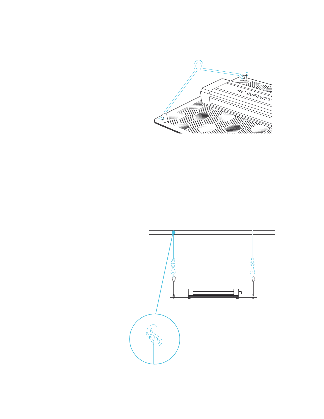
60
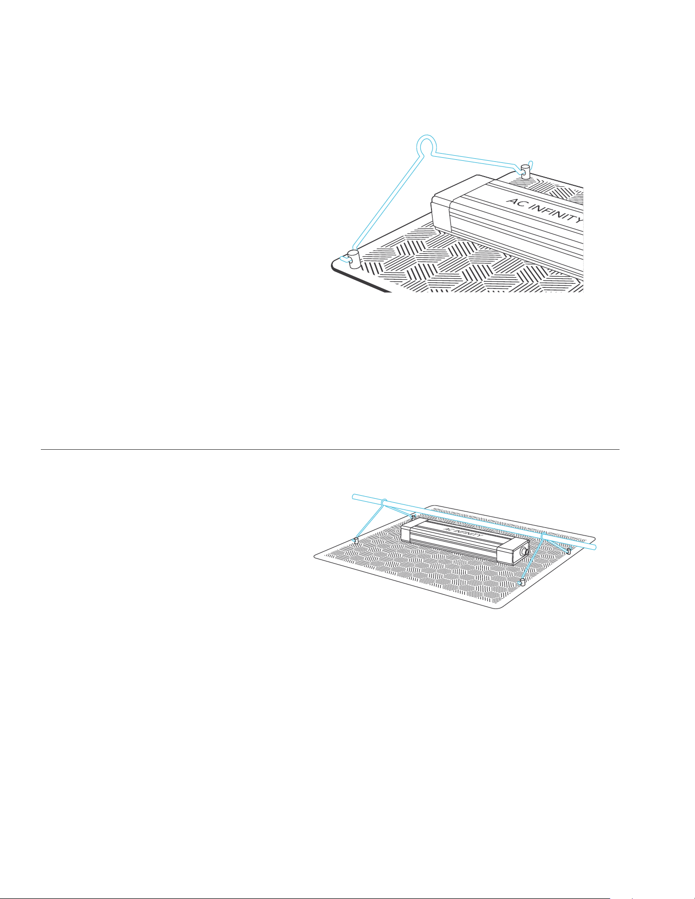
HANGING: IONBOARD
STEP 1
Insert the steel hooks into your grow
light’s slotted holes of the end caps.
STEP 2
Loop the rope clip hangers around your
grow tent’s support beams.
Hook the carabiners into the steel hooks.
GROW LIGHT SYSTEM
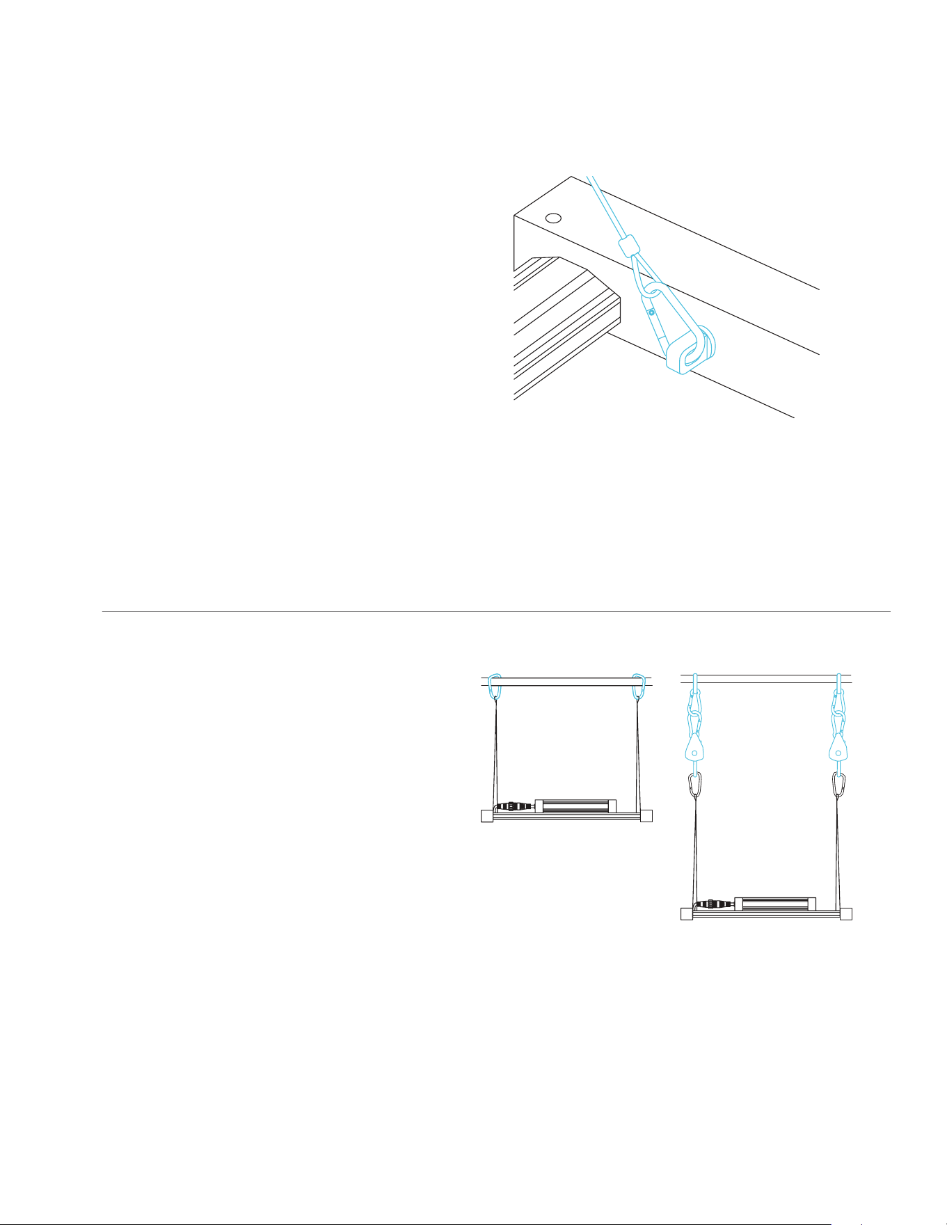
61
HANGING: IONFRAME EVO
STEP 1
Clip the lanyard hooks onto the four anchors
located at the corners of your grow light.
STEP 2
Clip the two carabiners onto your grow
tent's roof support beams.
You may also use rope clip hangers to
hang your grow light lower.
GROW LIGHT SYSTEM
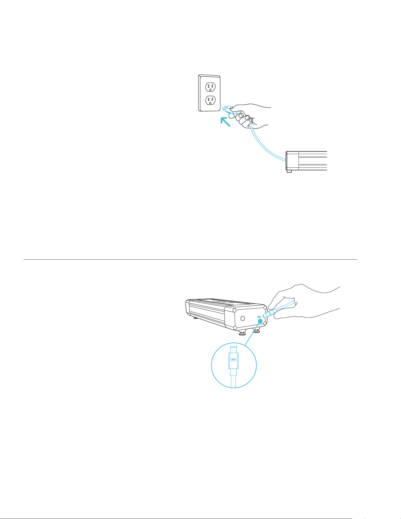
62
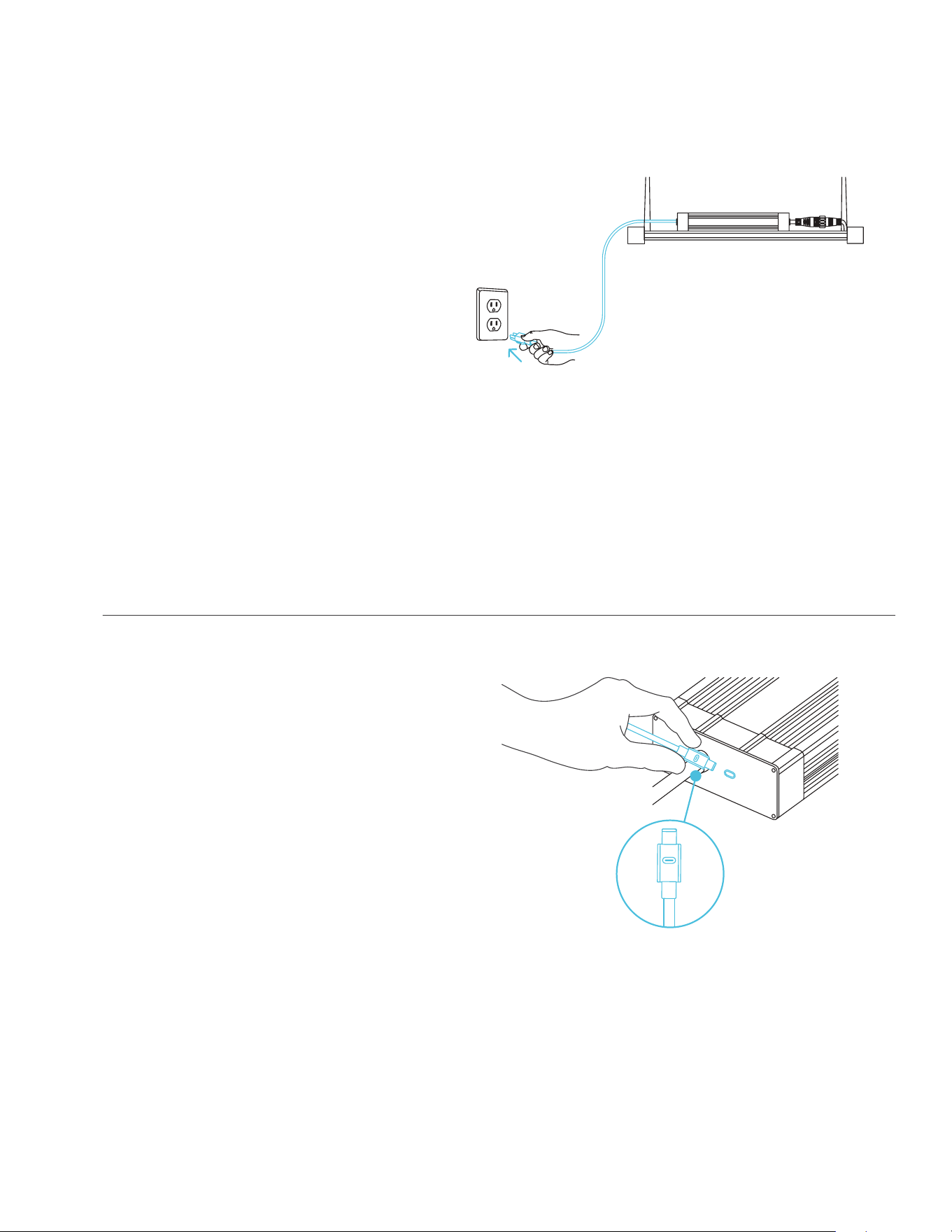
STEP 1
Plug the power cord into an AC power
outlet to power your grow light.
STEP 2
You may connect an external controller to
set smart programming.
Plug one end of the controller cord into
the LED driver, and the other end into
your chosen controller.
POWERING AND SETUP: IONBOARD
GROW LIGHT SYSTEM
63
STEP 2
Plug one end of the UIS extension cord
into the LED driver, and the other end
into your chosen controller.
STEP 1
Plug the power cord into an AC power
outlet to power your grow light.
POWERING AND SETUP: IONFRAME EVO
GROW LIGHT SYSTEM
64
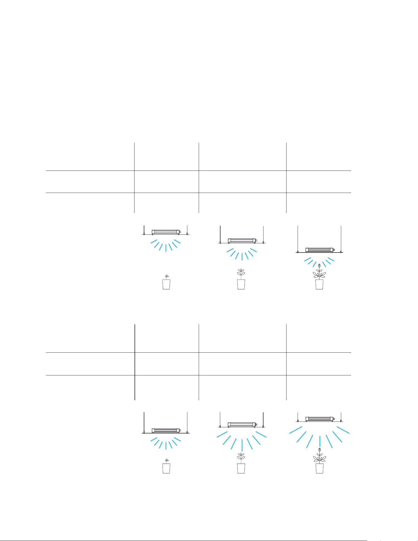
STARTER GUIDE: IONBOARD
The charts below offer suggested mounting heights and light intensities for each stage in the
growing process of your preferred method. These factors will vary based on the plant you are
growing. Height refers to distance from the canopy (tip of the plant).
Seeding
Stage
3 ft.
100%
2 ft.
100%
1.5 ft.
100%
HEIGHT
ADJUSTMENT
Height
Intensity
Vegetative
Stage
Flowering
Stage
Seeding
Stage
1.5 ft.
40%
1.5 ft.
80%
1.5 ft.
100%
LIGHT
ADJUSTMENT
Height
Intensity
Vegetative
Stage
Flowering
Stage
GROW LIGHT SYSTEM
65
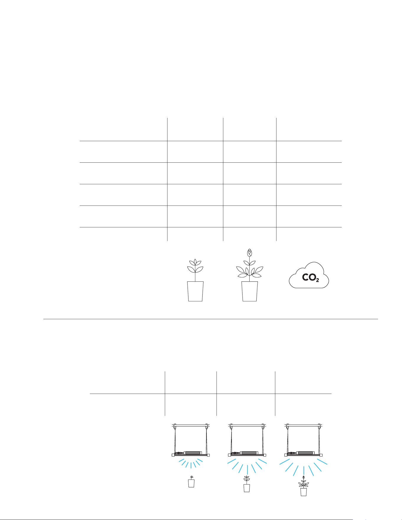
STARTER GUIDE: IONFRAME EVO
The chart below lists the coverage area of each grow light size in each growth stage. The
supplemental CO2 column refers to sealed grow spaces that use a CO2 enrichment system
with a 1300+ PPM.
The chart below offers suggested light intensities for each stage in the growing process of your
preferred method. These factors will vary based on the plant you are growing.
Intensity
LIGHT
ADJUSTMENT
40%
Seedling
Stage
80%
Vegetative
Stage
100%
Flowering
Stage
GROW LIGHT SYSTEM
3 x 5
Vegetative
Stage
4 x 4
5 x 5
6 x 6
7 x 7
1 x 3
Supplemental
CO
2
2 x 2
3 x 3
4 x 4
5 x 5
2 x 4
Flowering
Stage
3 x 3
4 x 4
5 x 5
6 x 6
IONFRAME EVO3
IONFRAME EVO4
IONFRAME EVO6
IONFRAME EVO8
IONFRAME EVO10
AREA
COVERAGE (FT.)
66
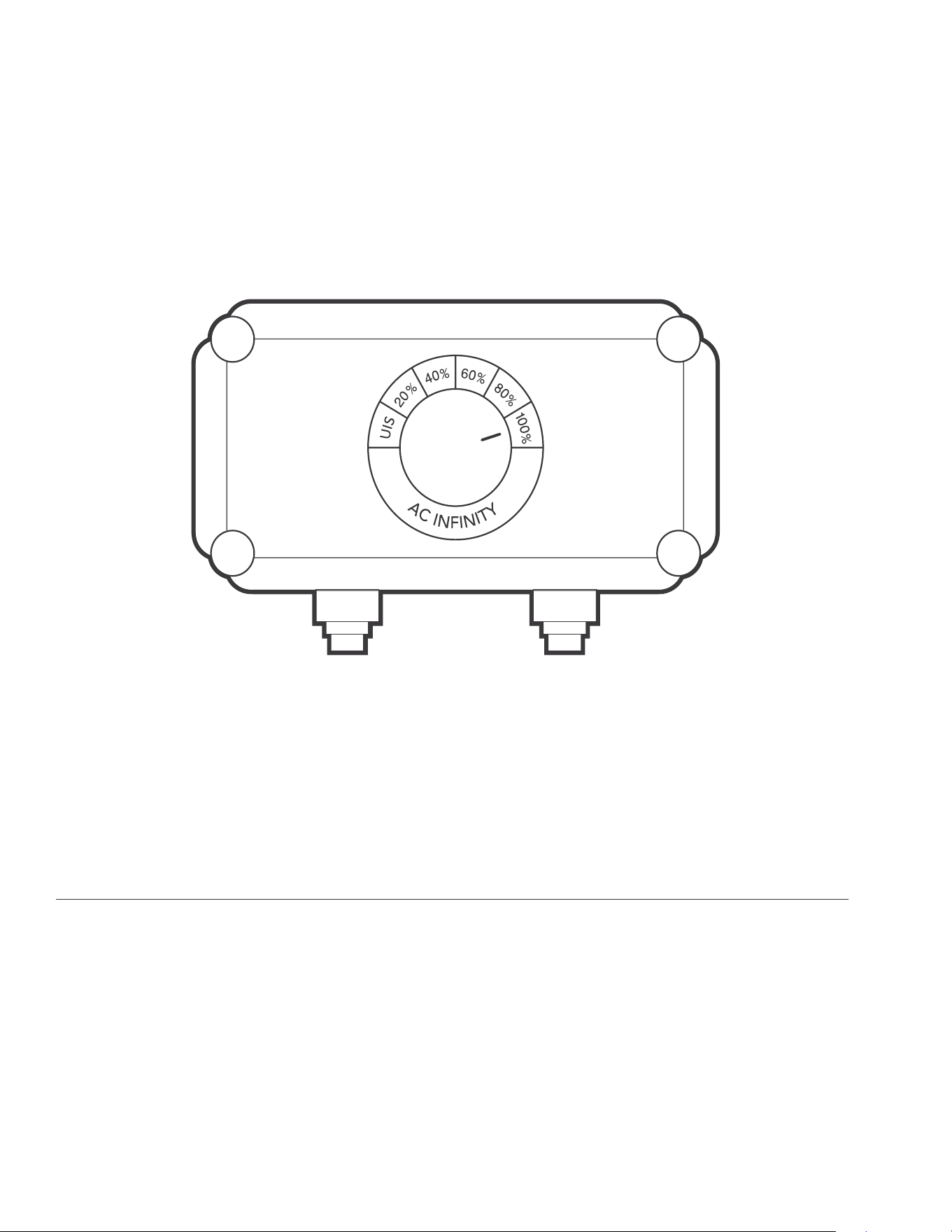
PROGRAMMING: IONBOARD
OFF/ON MODE
Turning the knob to UIS switches the grow light off, or passes control over to your smart
controller if one is connected.
INTENSITY LEVEL
Turning the knob from UIS will establish a set light intensity level in 20% increments, up to 100%.
GROW LIGHT SYSTEM

67
68
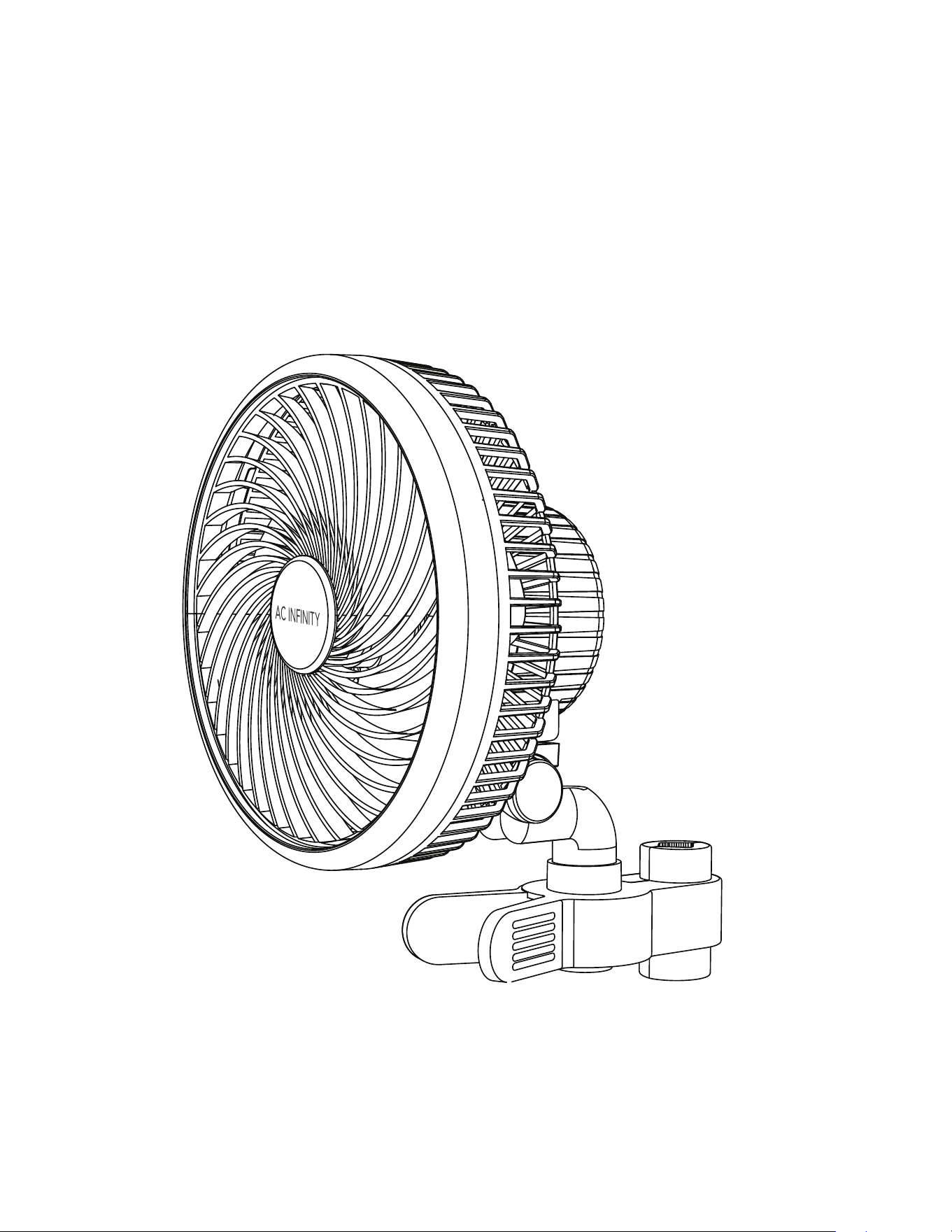
CLOUDRAY
OSCILLATING FAN SYSTEM
69
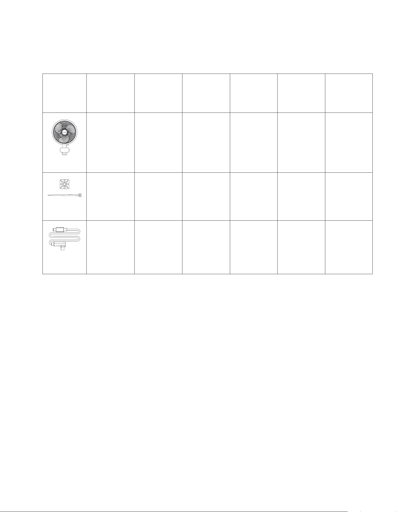
CLOUDRAY
PRODUCT CONTENTS
Advance Grow
Tent Kit (2x2)
AC-PKB22
Advance Grow
Tent Kit (2x4)
AC-PKB24
Advance Grow
Tent Kit (3x3)
AC-PKB33
Advance Grow
Tent Kit (4x4)
AC-PKB44
Advance Grow
Tent Kit (2x2)
COMPACT
AC-PKA22
Advance Grow
Tent Kit (5x5)
AC-PKB55
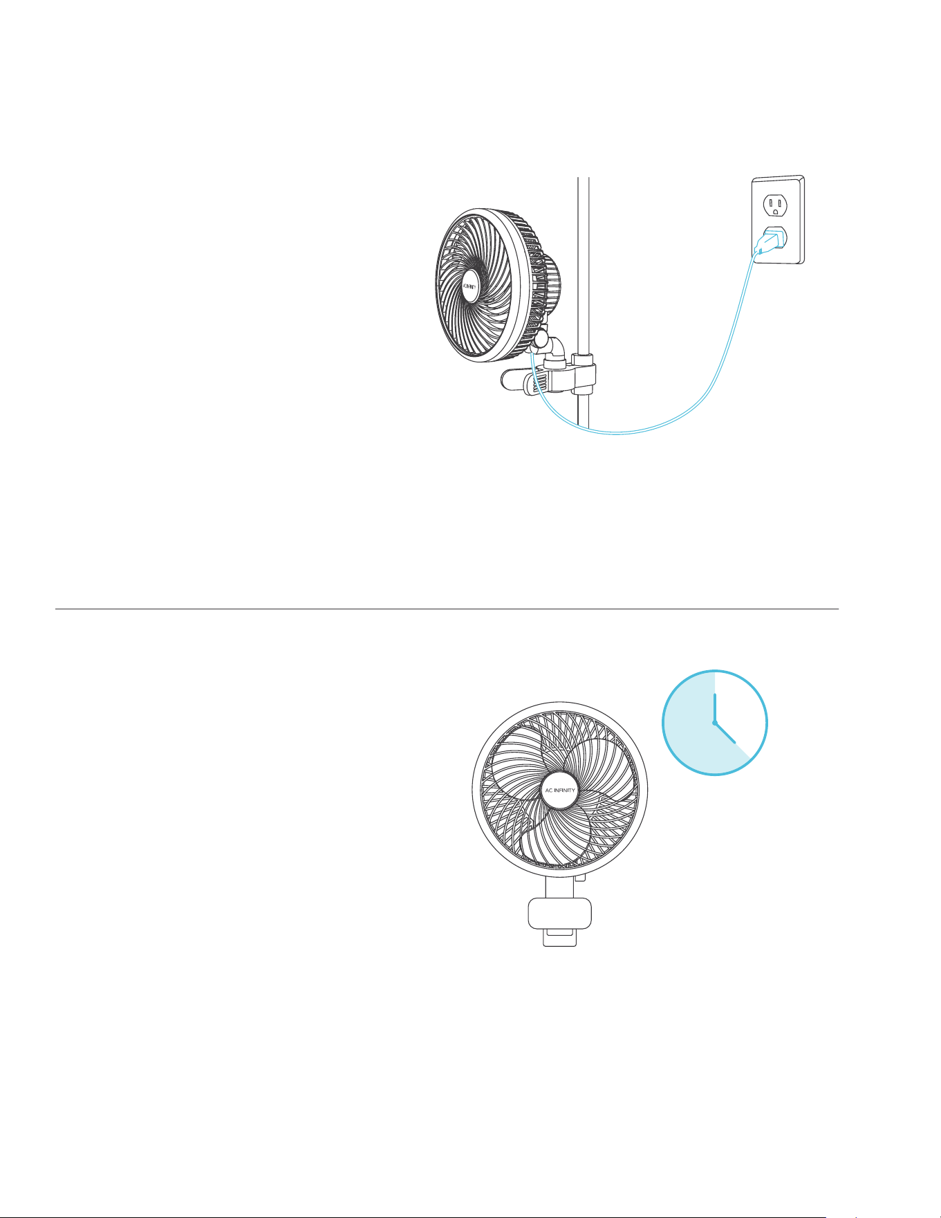
CLOUDRAY S6,
Oscillating
Clip Fan
x1
CLOUDRAY S6,
Oscillating
Clip Fan
x1
CLOUDRAY S6,
Oscillating
Clip Fan
x1
CLOUDRAY S6,
Oscillating
Clip Fans
x2
CLOUDRAY S6,
Oscillating
Clip Fan
x1
CLIP-ON FAN
CLOUDRAY S6,
Oscillating
Clip Fans
x2
x1 x1 x1 x2x1
WIRE TIE WITH
3M BASE
x2
UIS Male-Male
Controller Cord,
L-Shaped
x1
UIS Male-Male
Controller Cord,
L-Shaped
x1
UIS Male-Male
Controller Cord,
L-Shaped
x1
UIS Male-Male
Controller Cord,
L-Shaped
x2
UIS Male-Male
Controller Cord,
L-Shaped
x1
CONTROLLER
CORD
UIS Male-Male
Controller Cord,
L-Shaped
x2
70
CLOUDRAY
RECOMMENDED USAGE
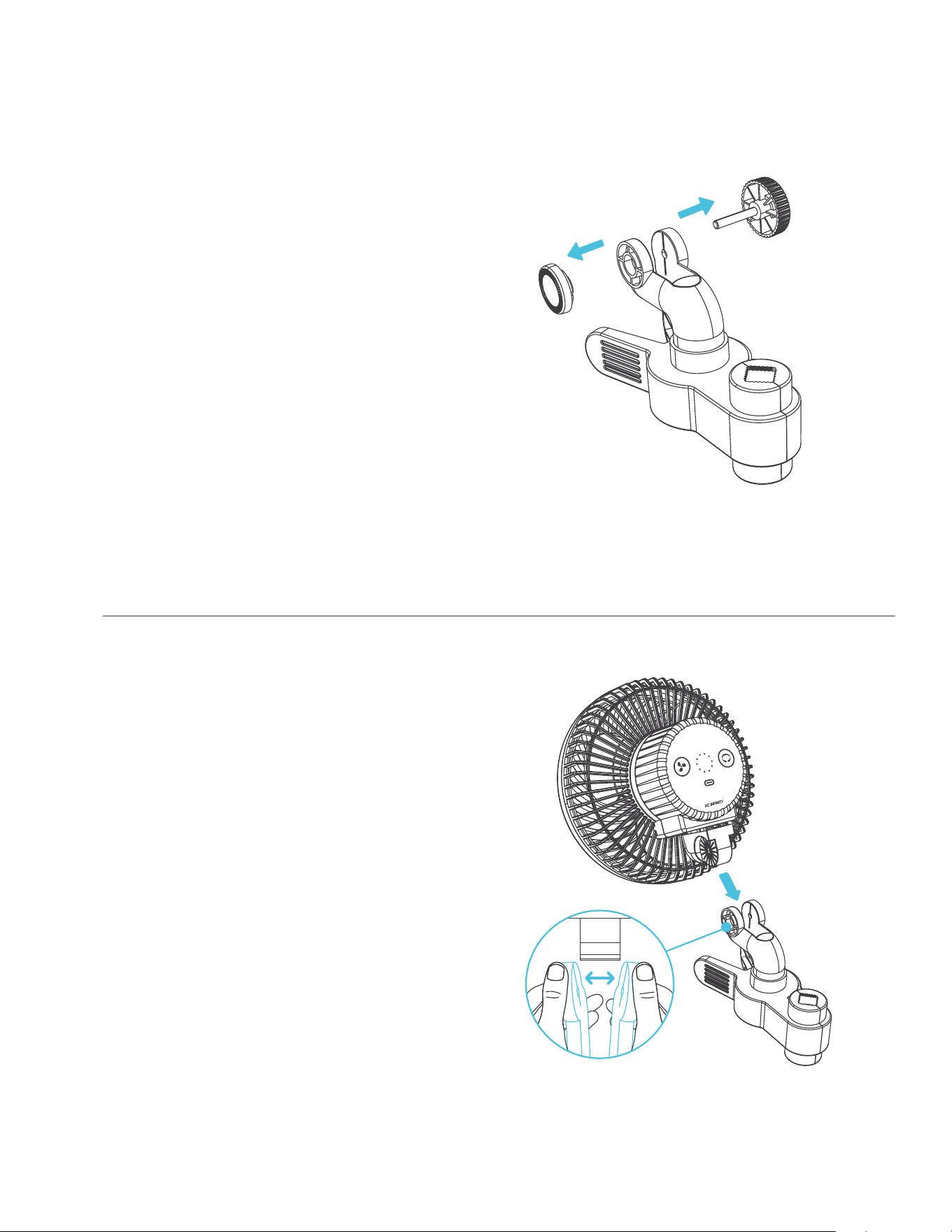
REDUCING CORD TENSION
Please make sure to provide enough
slack for the power cord and the extension
cord. The fan should be able to oscillate
freely without tugging on its cords.
MAXIMIZING LIFESPAN
This fan utilizes the latest in step motor
technology that allows it to operate 24
hours a day.
However, to maximize its lifespan, we
do not recommend having it oscillate
nonstop for more than 18 hours a day.
This will preserve the motor by
passively keeping it cool to prevent it
from wearing down.
18 hr.
ON
6 hr.
OFF
71
CLOUDRAY
INSTALLATION
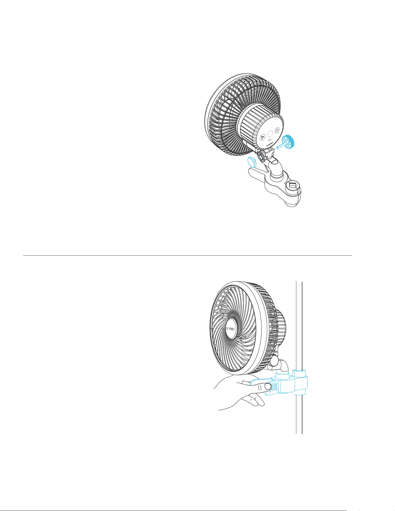
STEP 1
Twist to remove the bigger knob piece
from the grip clip.
Pull the smaller button piece from the
vice grip.
STEP 2
Slide the grip clip into the swivel as shown.
72
CLOUDRAY
INSTALLATION
STEP 3
Replace the knob and button on either
side of the mounting point as desired.
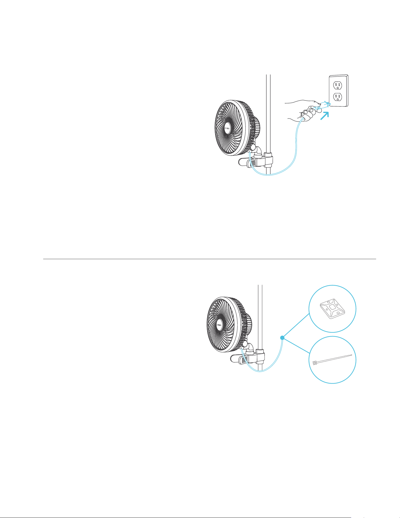
STEP 4
Clamp the fan onto a pole or post.
73
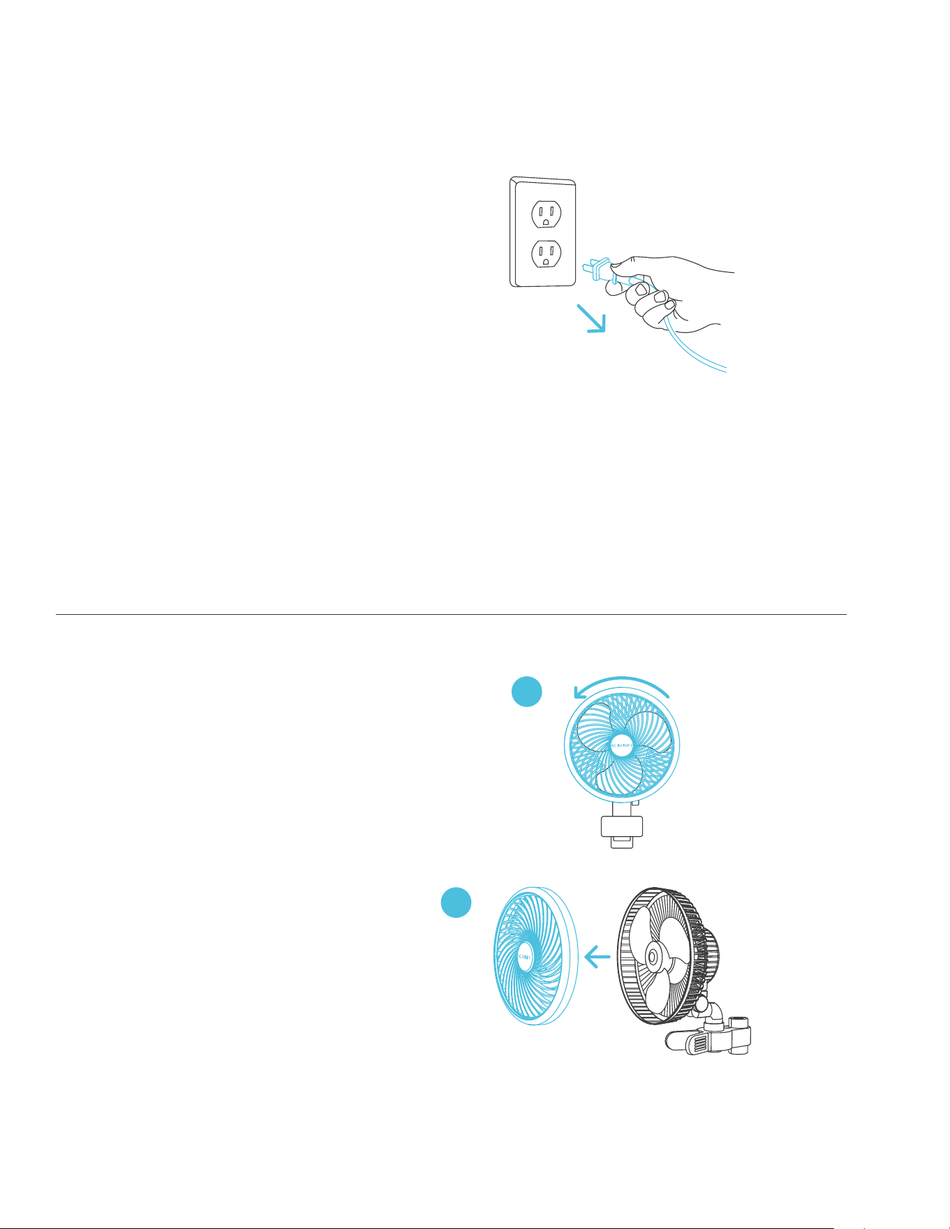
STEP 5
Plug the fan’s power cord into an AC
power outlet to power the fan.
Plug the fan into the closest AC outlet to
allow for cable slack and avoid
cable tension.
STEP 6
You may manage the cords using the
included cable ties or cable mounting set.
Adhere the tie mount onto a clean
surface. Loop the wire tie into the mount
and around the cables.
CLOUDRAY
INSTALLATION
74
CLOUDRAY
CLEANING
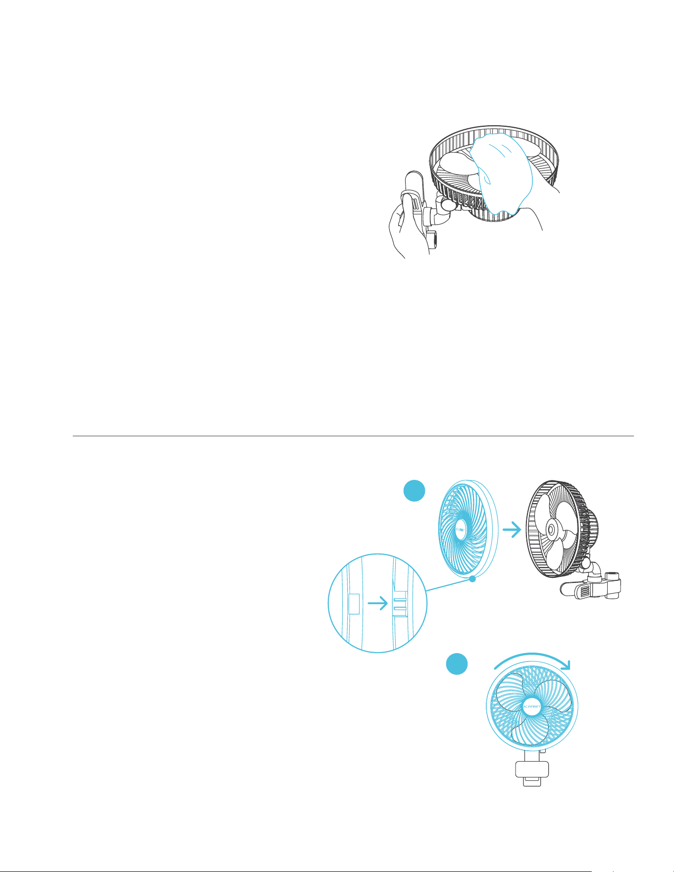
STEP 1
Unplug your clip fan.
STEP 2
Remove the front grille by twisting the
grille counter-clockwise and pulling it off.
A
B
75
CLOUDRAY
CLEANING
STEP 4
Realign the grille over your clip fan and
twist clockwise to lock it in place.
STEP 3
Wipe off any dust and debris from the
grille and fan blades using a damp cloth.
Set aside to dry as needed.
A
B
76
CLOUDRAY
PROGRAMMING
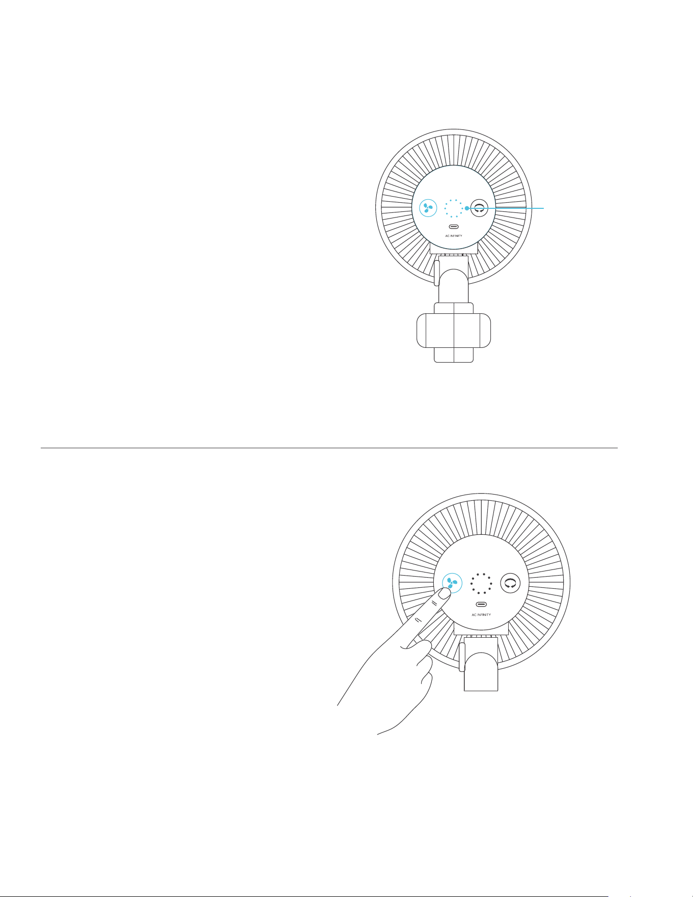
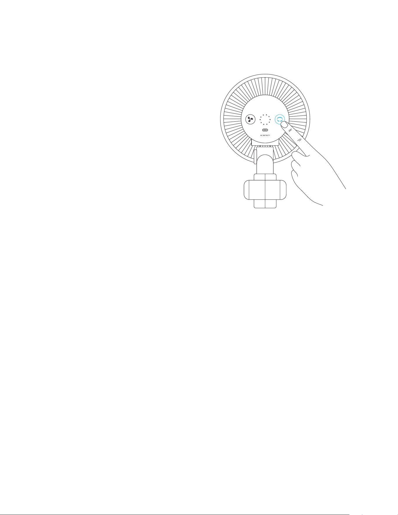
FAN SPEED ADJUSTING
Your clip fan features a button that
cycles through the fan speed from 0-10,
indicated by the ring of LED lights.
Press the speed button to increase the
fan speed level by one.
Pressing the button past speed 10 will
cycle the fan speed back to 0.
POWERING ON/OFF
Hold the speed button for 4 seconds to turn
the fan OFF. Pressing it again from OFF will
turn the fan ON at its last speed setting.
Fan Speed
Indicator
77
CLOUDRAY
PROGRAMMING
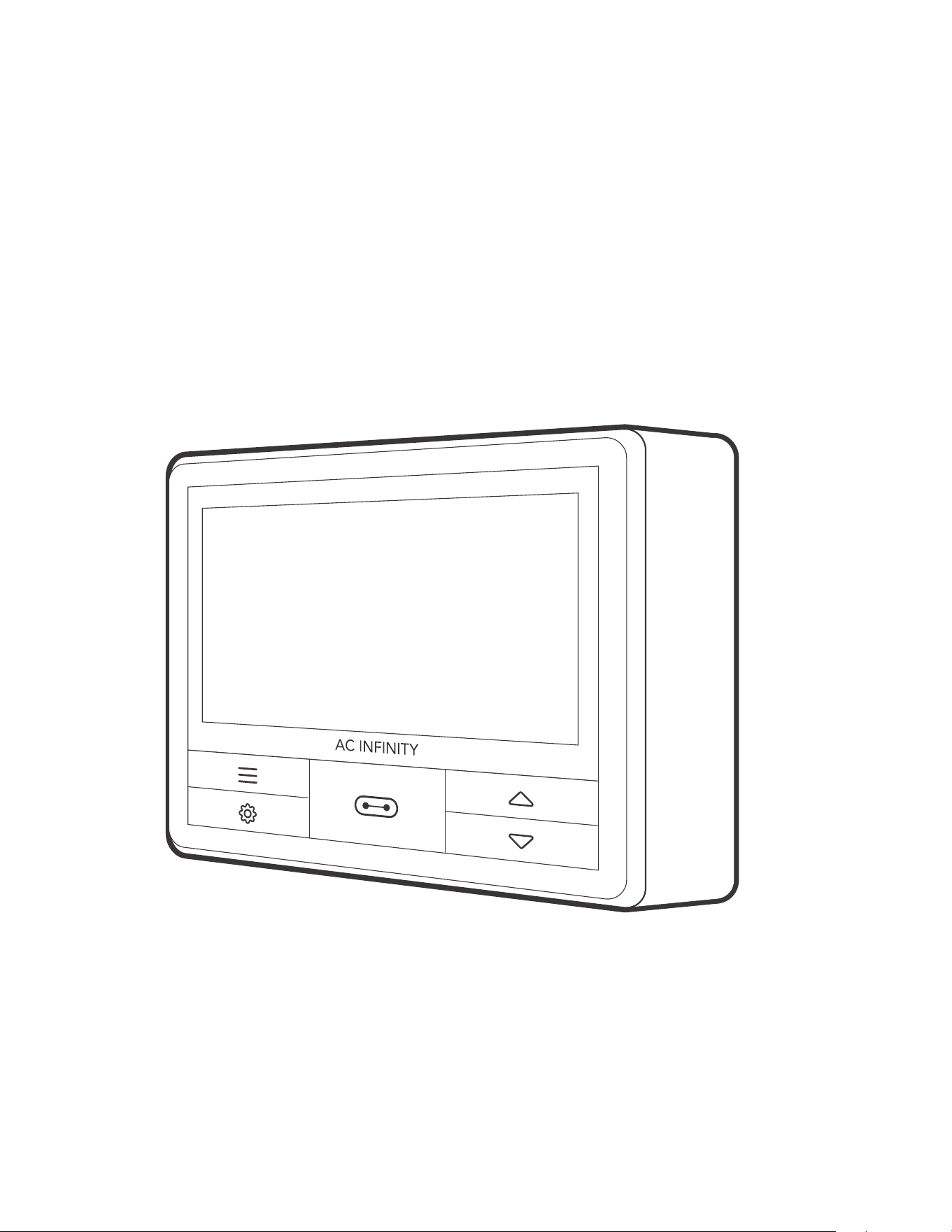
OSCILLATION
In addition to the standard features,
S-Series models can oscillate to provide
airflow at a wide angle. The oscillation
function is manually activated using the
oscillation button and cannot be controlled
using external UIS programming.
If set to off, your clip fan will not oscillate
regardless of any external programs.
If set to on, oscillation will automatically
start if the external program activates your
clip fan to turn ON. Oscillation will then
automatically stop if the external program
deactivates your clip fan to turn OFF.
78
CONTROLLER 69 PRO
UIS
TM
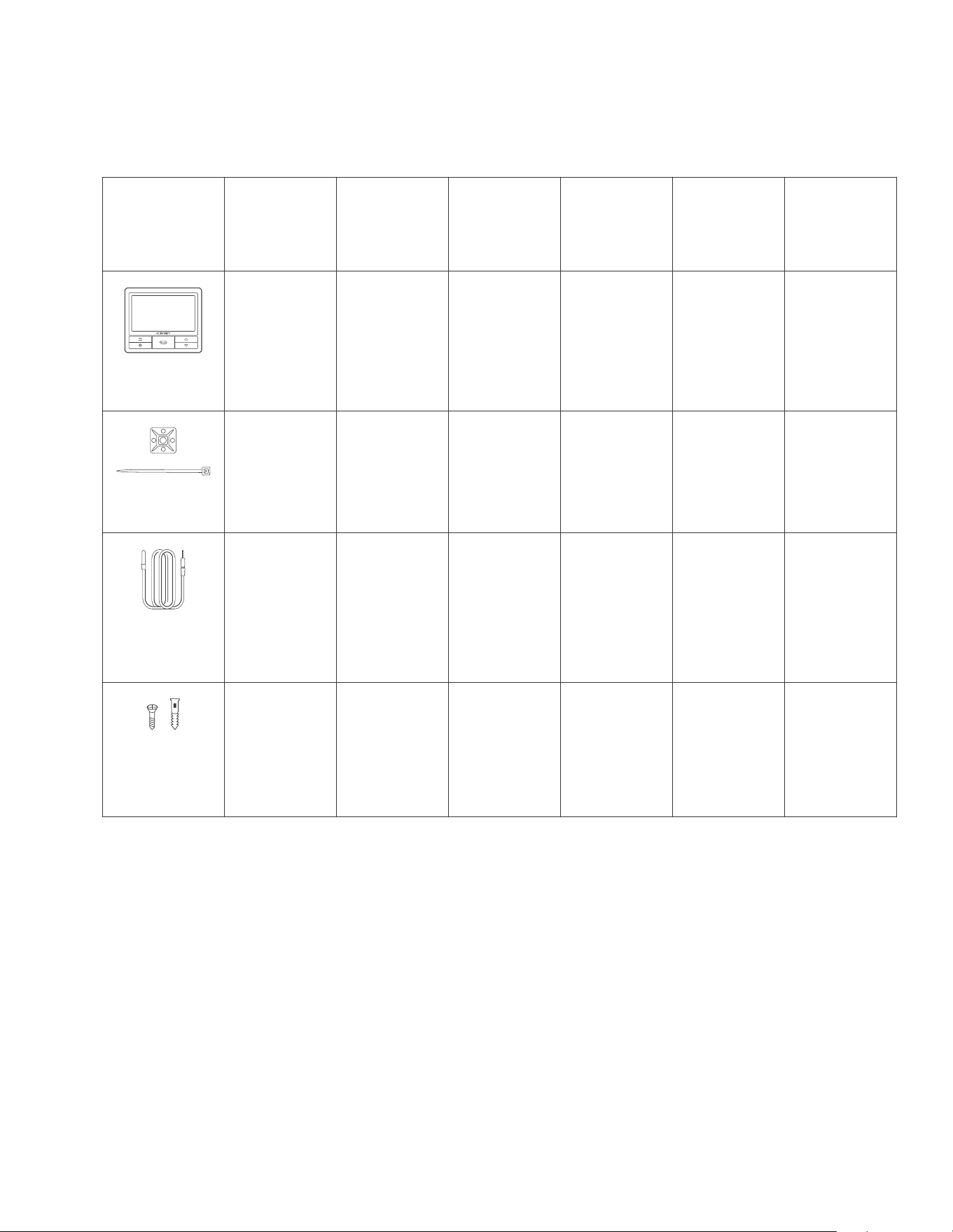
MULTI-DEVICE CONTROLLER
79
CONTROLLER 69 PRO
PRODUCT CONTENTS
Advance Grow
Tent Kit (2x2)
AC-PKB22
Advance Grow
Tent Kit (2x4)
AC-PKB24
Advance Grow
Tent Kit (3x3)
AC-PKB33
Advance Grow
Tent Kit (4x4)
AC-PKB44
Advance Grow
Tent Kit (2x2)
COMPACT
AC-PKA22
Advance Grow
Tent Kit (5x5)
AC-PKB55
CONTROLLER
69 PRO, 4 Ports
x1
CONTROLLER
69 PRO, 4 Ports
x1
CONTROLLER
69 PRO, 4 Ports
x1
CONTROLLER
69 PRO, 4 Ports
x1
CONTROLLER
69 PRO, 4 Ports
x1
GROW TENT
CONTROLLER
CONTROLLER
69 PRO, 4 Ports
x1
x1 x1 x1 x1x1
WIRE TIE WITH
3M BASE
x1
x1 x1 x1 x1x1
TEMPERATURE
AND HUMIDITY
SENSOR PROBE
x1
x2 x2 x2 x2x2
CONTROLLER
MOUNTING
SCREWS WITH
PLASTIC ANCHOR
x2
80
POWERING AND SETUP
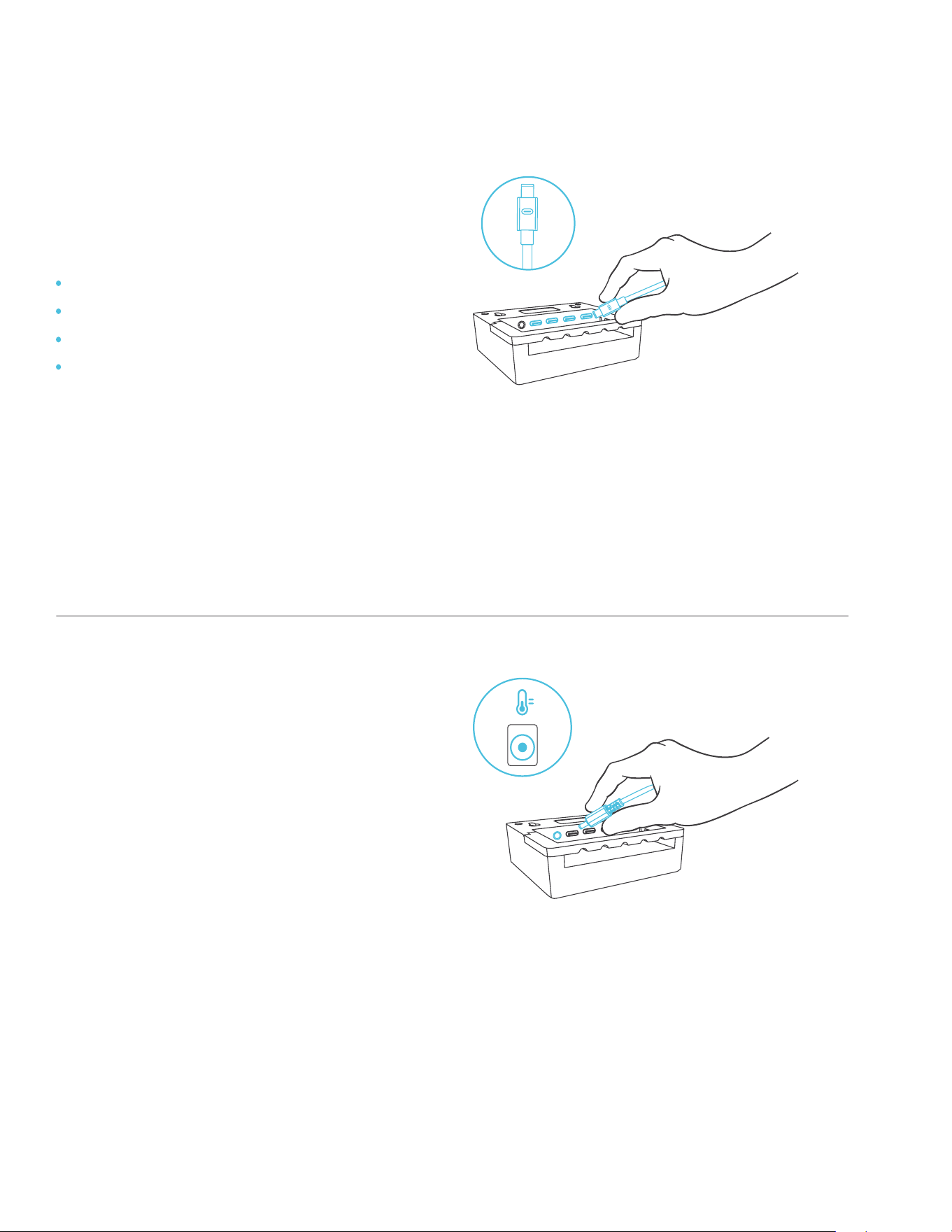
STEP 1
Plug your devices’ UIS connectors into
the following numbered ports:
STEP 2
Plug the sensor probe into the
controller’s 3.5mm jack. Set the probe
near your plants in your grow tent for the
most accurate reading.
Keep the probe cord away from your
HID* grow light ballast’s power cord to
ensure the controller properly detects
climate conditions.
*MH, HPS, CMH, or CHPS
Port 1 – Inline Fan
Port 2 – Grow Light
Port 3 – Clip Fan
Port 4 – Clip Fan (AC-PKB44 and
AC-PKB55 models only).
CONTROLLER 69 PRO
81
POWERING AND SETUP
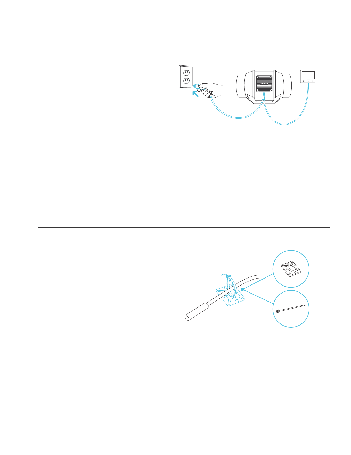
STEP 4
You may use the included tie mounts,
wood screws, and wire ties to manage
the cords.
Secure the tie mounts onto a surface
using the wood screws. Loop the wire
ties around the cords into the tie mounts.
STEP 3
Plug your devices’ power cord into an
AC power outlet to power them and
the controller.
CONTROLLER 69 PRO
82
MOUNTING
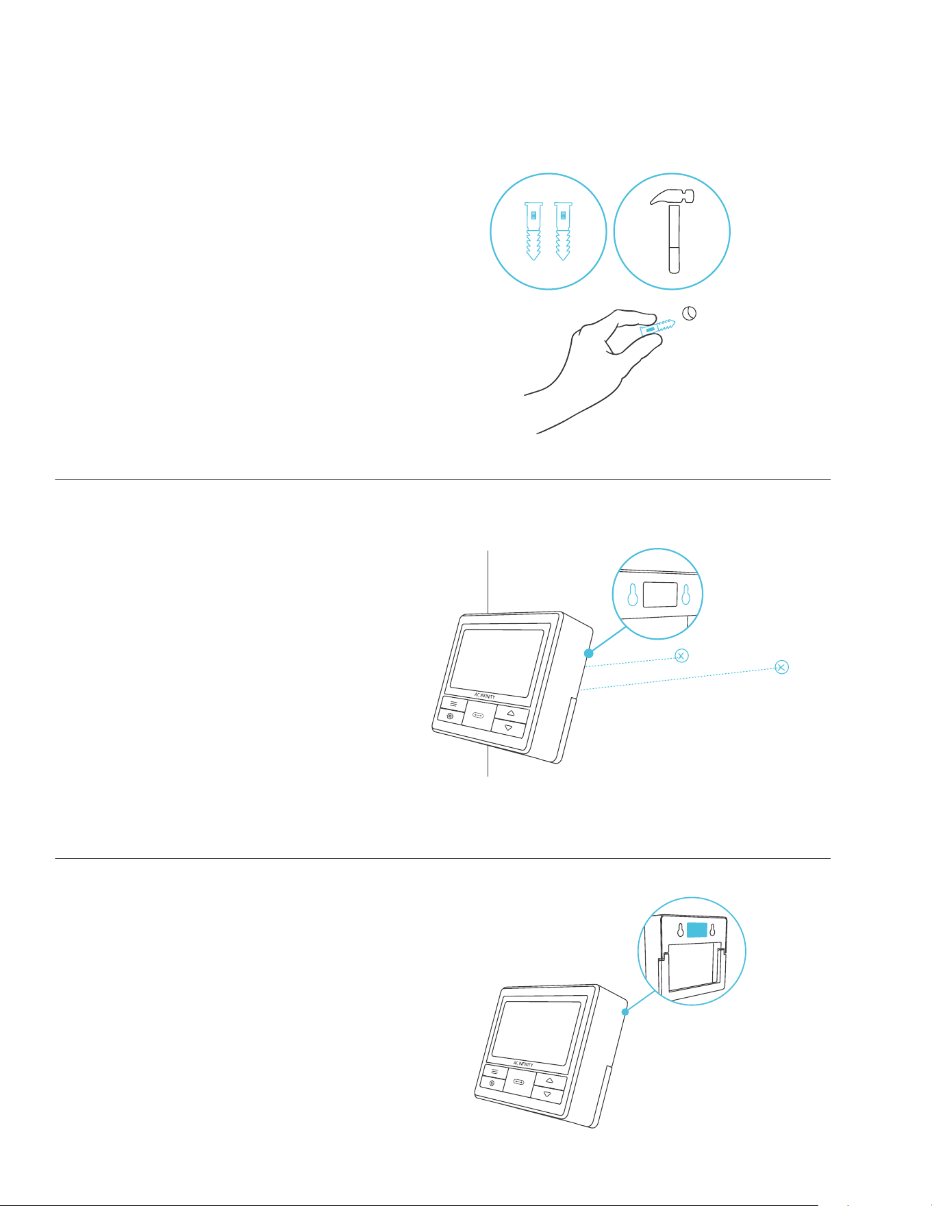
STEP 1 — WALL MOUNTING
Locate a spot free of obstruction and
secure the anchors into your wall. Twist
the wood screws into the anchors.
STEP 2 — WALL MOUNTING
Hang the controller by the screws using
the holes on the backside.
CONTROLLER 69 PRO
MAGNET MOUNTING
You may also mount the controller onto
a steel surface using the magnet located
behind the label.
83
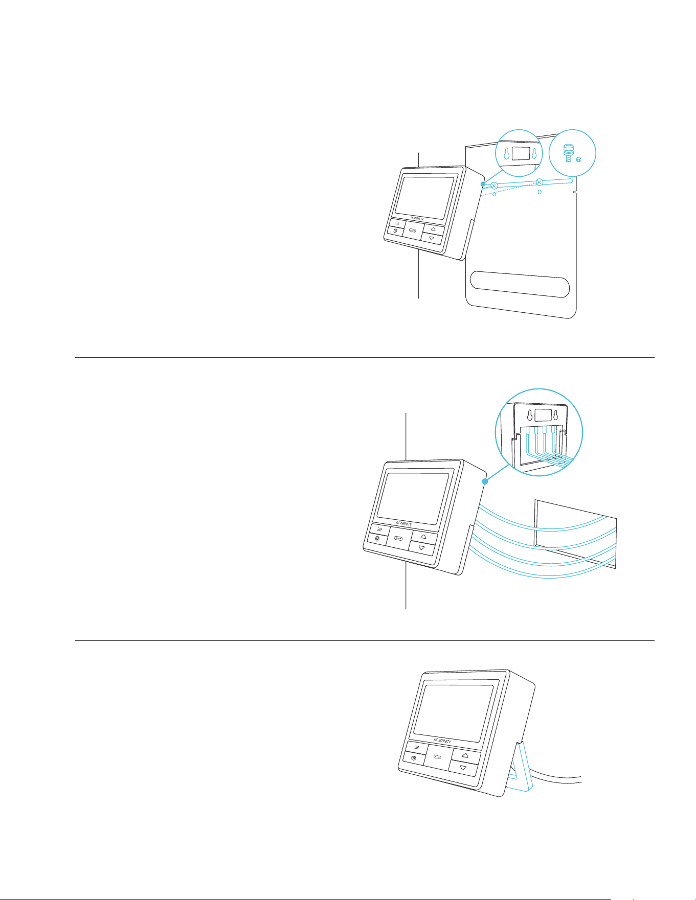
MOUNTING
KICKSTANDING
Open the stand behind the controller to
set it tilted on your desktop.
CORD ARRANGEMENT
Cords may be routed into or outside of
the kickstand grooves, and through a cut
hole behind the controller.
CONTROLLER 69 PRO
PLATE MOUNTING
Screw the bolts into the slot or mounting
holes at the upper half of the plate.
Hang the controller by the bolts using the
holes on the backside.
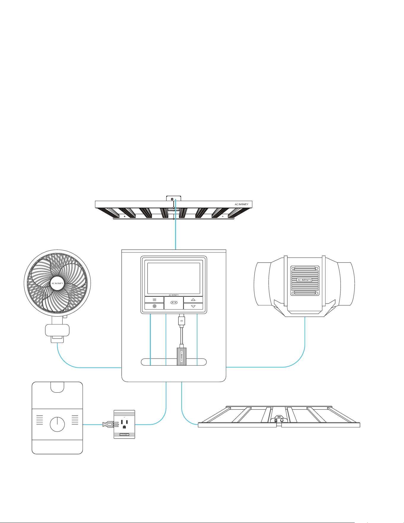
84
UIS™ PLATFORM
CONTROLLER 69 PRO
The UIS
TM
platform enables you to connect a single central controller with several grow devices
simultaneously. By creating this fully integrated system, you can power and program all your
devices together or separately for optimized grow tent management.
Your grow system can be regulated using your controller hub or remotely on the AC Infinity app
(paired with compatible controllers), where you will have access to automation programming
and climate data.
You can also connect your favorite grow light and outlet device to integrate them into the UIS
platform using our RJ11/12 adapter and control plug module.
Grow devices will be sold separately and may still be in
development at the time of your purchase of this product.
85
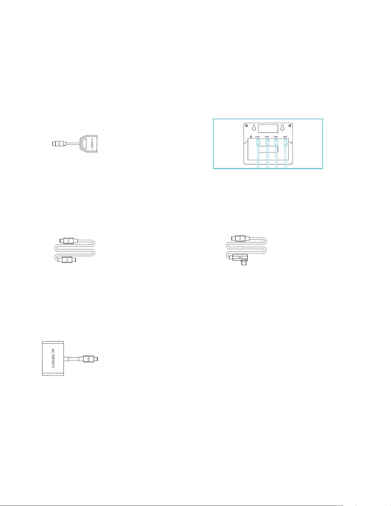
CONTROLLER CORD
Use male-to-male UIS controller cords to connect devices with female UIS ports at an extended
range from your controller.
4-PORT SPLITTER*
The expansion dongle will allow you to connect 4 devices with a single port and can support
additional splitters to create up to three tiers of expansion ports. Intended for exclusive use with
AC Infinity controllers built with UIS ports.
MOLEX ADAPTER*
Use a Molex adapter to plug inline fans with 4-pin Molex connectors into this controller. Plug
your fan's Molex connector into the adapter. Then plug the adapter into the controller.
*Not included
UIS
TM
COMPATIBILITY
UIS M - M
CONTROLLER CORD
(BOX D)
L-SHAPED UIS M - M
CONTROLLER CORD
(BOX E)
UIS M - 4PIN F
ADAPTER
UIS M - M
4-PORT SPLITTER
1
CONTROLLER 69 PRO
86
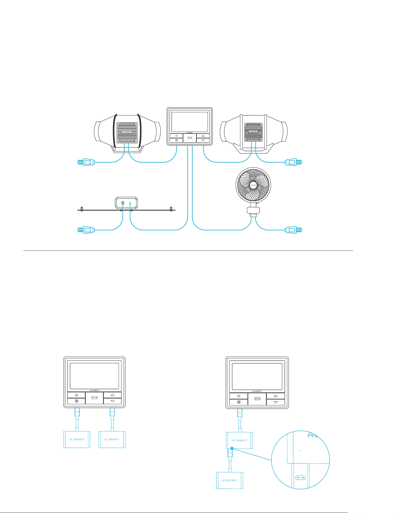
The CONTROLLER 69 PRO is built with four ports that enable you to power and control multiple
devices at the same time. See image below for a sample configuration.
USING THE DONGLE
When using a 4-port dongle, plug your
first device into Port 1 for the controller to
recognize as the primary device.
All other devices plugged into the dongle
will follow programming intended for the
device plugged into Port 1.
EXTENDING THE CHAIN
When plugging additional dongles into Port
1, all devices plugged into this chain must be
of the same type (ex. grow lights of any size)
regardless of the length of the dongle chain.
1 1
ADDING MORE DEVICES
CONTROLLER 69 PRO
1
1
1
87
ADDING MORE DEVICES
CONTROLLER 69 PRO
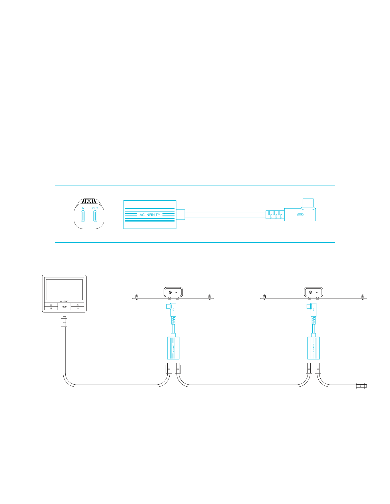
DAISY-CHAINING
Each of the included controller’s ports can support up to 20 devices using a daisy-chain adapter
(not included). All devices must be from the same series but can be of differing sizes.
Plug the male end of the daisy-chain adapter into your device.
Connect your UIS controller to the daisy-chain adapter’s INPUT port using a M-M connector
cord. Using an extension cord, attach the daisy-chain adapter’s OUTPUT port to another
adapter’s INPUT port. You can also link the OUTPUT port to another UIS device to end the chain.
88
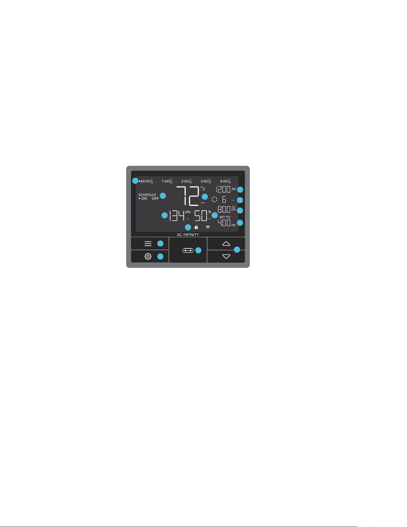
PROGRAMMING
5. PORTS
Displays all connected
devices as well as their
current level. Digits are
displayed by the UIS symbol
when a device is plugged
into its corresponding port.
4. UP/DOWN BUTTONS
Adjusts the value of your
current mode. The up
button increases and down
button decreases the
setting. Hold both to reset
values to OFF/Default.
7. PROBE HUMIDITY
Displays the current humidity
that the probe is measuring.
Shows "--" if no probe is
plugged in. Includes a trend
indicator that signals a rise,
stability, or fall in humidity
within the last hour.
6. PROBE TEMPERATURE
Displays the current
temperature that the probe
is detecting. Shows “--”
if no probe is plugged in.
Includes a trend indicator
that signals a rise, stability,
or fall in temperature within
the last hour.
3. SETTING BUTTON
Cycles through the controller’s
settings: DISPLAY, CLOCK,
°F / °C, CALIB. T° / H% / kPa,
TRANS. T° / H% / kPa,
BUFF. T° / H% / kPa, and
LEAF OFFSET.
2. MODE BUTTON
Cycles through the controller’s
modes: OFF, ON, AUTO (4
triggers), VPD (2 triggers), TIMER
TO ON, TIMER TO OFF, CYCLE
(ON and OFF), and SCHEDULE
(ON and OFF).
1. PORT BUTTON
Cycles through up to four
connected devices. Each
device is programmed
independently, or
together when navigating
to ALL.
14. ALERT ICONS
Displays alerts and statuses
of the controller, including
the controller lock, CLIMATE
alert, and TIMER alert.
13. USER SETTING
Displays the value of
your current mode. Use
the up or down buttons
to adjust the value.
12. COUNTDOWN
Displays the countdown of the
TIMER TO ON, TIMER TO OFF,
CYCLE, or SCHEDULE mode
activates or deactivates the devices.
TO ON shows the amount of time
left before the devices turn on. TO
OFF shows the amount of time left
before the device turn off.
11. CURRENT LEVEL
Displays the connected
devices' current setting.
Includes a trend indicator
that signals if the setting is
currently rising, falling, or
holding steady.
10. CURRENT TIME
Displays the current
time. The internal
battery sustains the
clock so it does not
default to 00:00 if
power is cut off.
9. CONTROLLER MODE
Displays the controller's
current mode. Pressing the
mode button cycles through
the available modes.
8. PROBE VPD
Displays the current VPD
that the probe is detecting (in
kPa). Shows “--” if no probe is
plugged in. Includes a trend
indicator that signals a rise,
stability, or fall in VPD within
the last hour.
CONTROLLER 69 PRO
1
2
3
4
6
8
9
10
11
12
13
14
5
7
89
PROGRAMMING
ALL PORTS
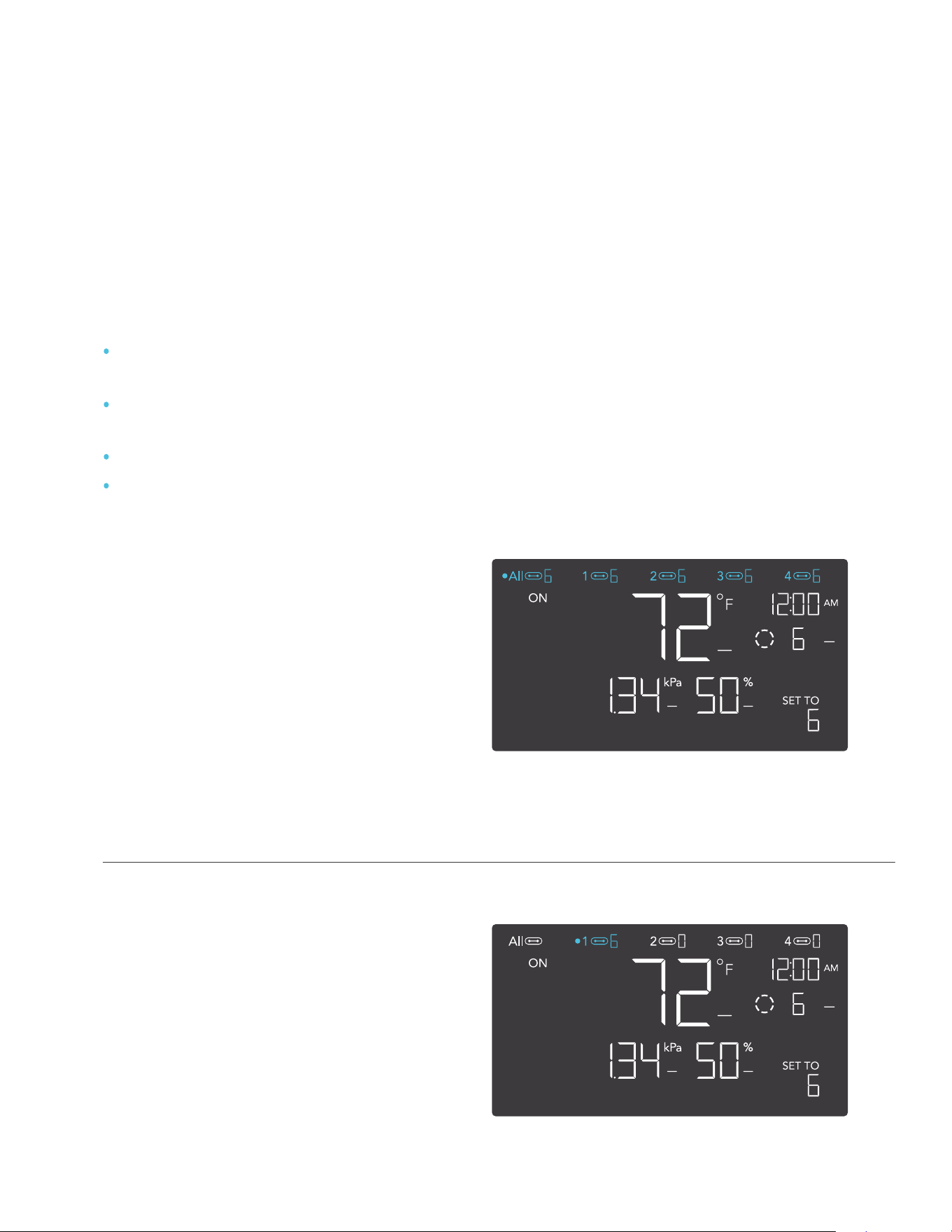
Navigate to the ALL port to set
simultaneous programming for all
connected devices.
Programming set in this port mode
applies to all connected devices, but will
not be active if you navigate to other
ports. Re-entering the ALL port will
resume its programming.
INDIVIDUAL PORT
Navigate to a numbered port with
a connected device to set
individual programming.
Programming will run in the background
even while you navigate to other
numbered ports.
PORTS
Pressing the port button will cycle through the controller’s available ports: ALL, 1, 2, 3, and 4.
Dot indicates the current device. No digit is displayed if a device is not plugged into the
corresponding port.
The controller is pre-programmed with the following settings:
Port 1 – Inline Fan set to Fan Speed Level 5 scheduled between 6:00pm and 12:00pm,
and to Level 2 scheduled between 12:00pm and 6:00pm.
Port 2 – Grow Light set to Brightness Intensity Level 10 scheduled between 6:00pm
and 12:00pm and to Level 0 scheduled between 12:00pm and 6:00pm.
Port 3 – Oscillating Fan set to Level 5.
Port 4 – Oscillating Fan set to Level 5 (if applicable).
CONTROLLER 69 PRO
90
PROGRAMMING
CONTROLLER MODES
Pressing the mode button will cycle through the controller’s available programming modes: OFF,
ON, AUTO (4 triggers), VPD (2 triggers), TIMER TO ON, TIMER TO OFF, CYCLE (On and Off),
and SCHEDULE (On and Off).
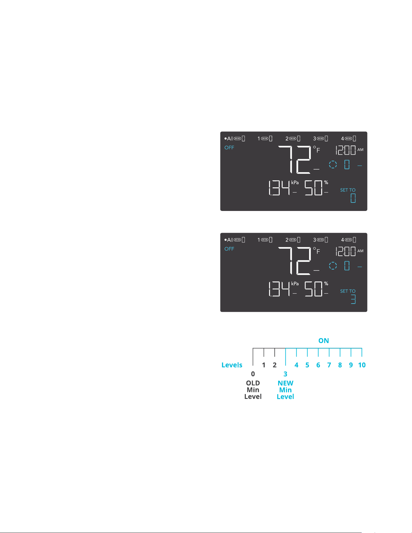
OFF MODE
Your devices will not run while in this mode.
The OFF Mode setting also serves as the
minimum level the other modes will run at
while triggered OFF.
MINIMUM LEVEL
Your devices will run at the level set in OFF
Mode, as the minimum level, when triggered
to turn OFF. These other modes include
the AUTO Mode, CYCLE Mode, TIMER
TO ON Mode, TIMER TO OFF Mode, and
SCHEDULE Mode.
They will run continuously until triggered ON,
at which point they will run at the level set in
ON Mode.
If you want your devices to turn off completely
when they're triggered to be OFF, set the OFF
Mode level to zero.
CONTROLLER 69 PRO
*Example shown
91
PROGRAMMING
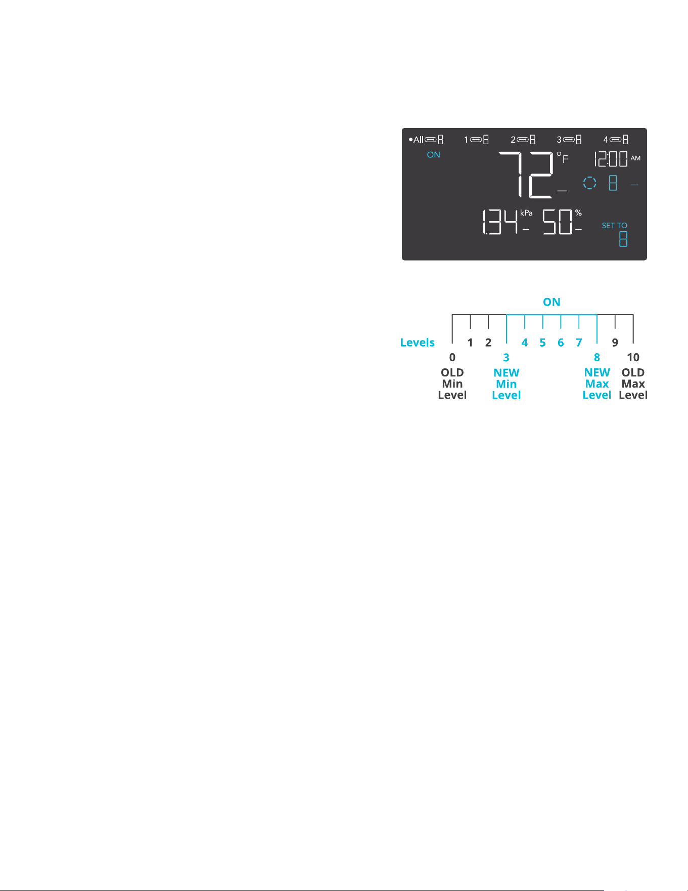
MAXIMUM LEVEL
Your devices will run at the level set in ON
Mode, as the maximum level, when triggered
ON, as well as in the AUTO Mode, CYCLE
Mode, TIMER TO ON Mode, TIMER TO OFF
Mode, and SCHEDULE Mode.
Do not set the ON Mode figure to zero or
your devices will turn off when it’s triggered
ON in all modes.
ON MODE
Your devices will actively run at the level
set here, regardless of the probe’s reading.
The ON Mode setting also serves as the
maximum level the other modes will run at.
CONTROLLER 69 PRO
*Example shown
92
PROGRAMMING
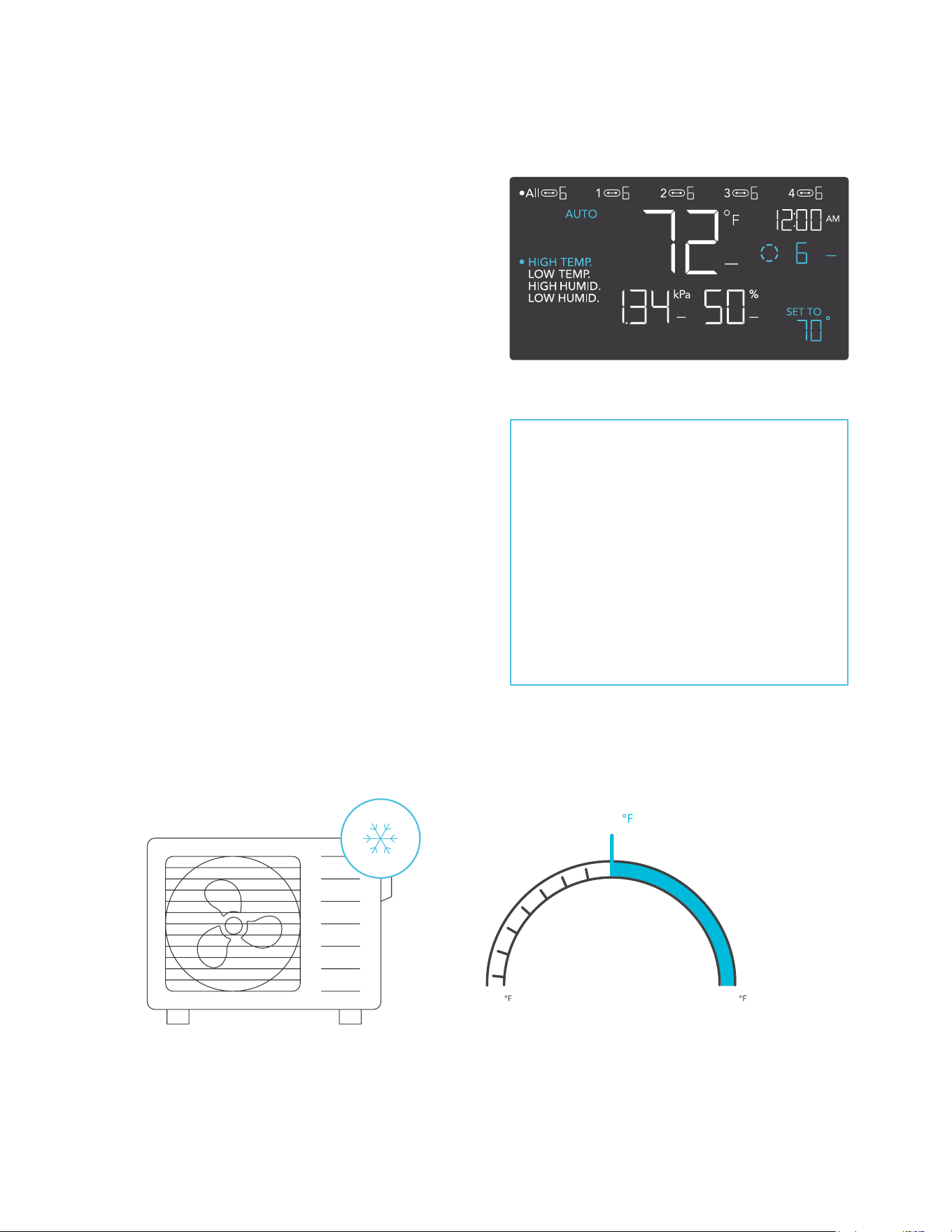
AUTO MODE (HIGH TEMPERATURE TRIGGER)
Pressing the up or down button sets the high
temperature trigger. The devices will activate if the
probe’s reading meets or exceeds this threshold.
Once triggered, the devices will gradually ramp up
to the level set in ON mode. If the probe’s reading
falls below this trigger point, the devices will
gradually slow down to a stop or at the level set in
OFF mode.
You may set this trigger below the low temperature
trigger to create a specific range in which the
devices are active.
This is typically used with devices like air
conditioners and cooling fans to help lower the
temperature when it gets too hot. For example, if
you set a high temperature trigger of 70°F, then
your device will activate when the temperature
reaches 70°F or higher, and turn off when it falls
below 70°F. Products shown here may still be
in development.
Any of the four trigger points can
activate while you are in AUTO
Mode, even if you are viewing
another trigger point. Please set
a trigger point to OFF if not in
use, by holding down the up and
down button. If there is a level
set in OFF Mode other than zero,
the devices will run at that level
when triggered to turn o.
ON
HIGH TEMPERATURE
TRIGGER POINT
32 194
COLDER HOTTER
OFF
70
CONTROLLER 69 PRO
93
PROGRAMMING
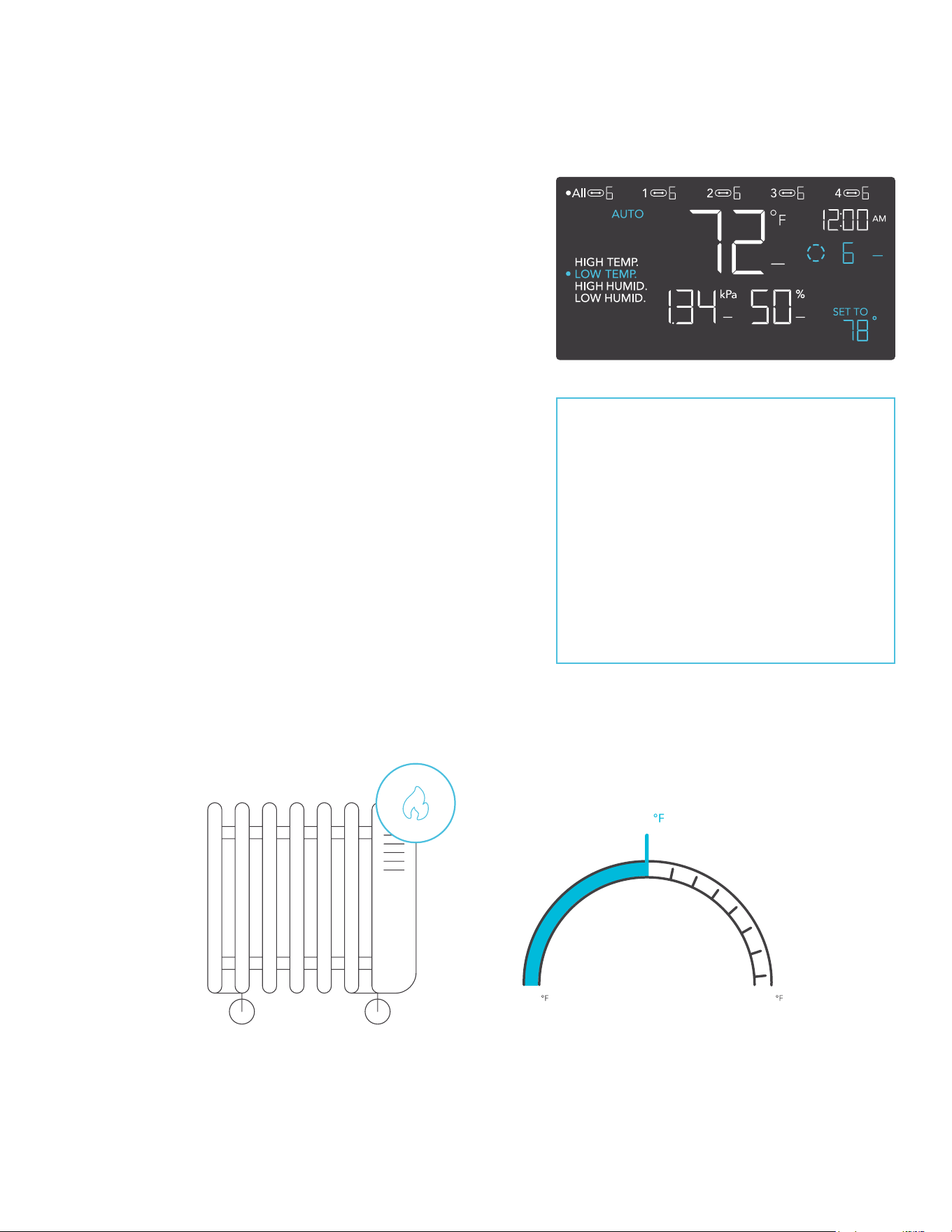
AUTO MODE (LOW TEMPERATURE TRIGGER)
Pressing the up or down button sets the low
temperature trigger. The devices will activate if the
probe’s reading meets or falls below this threshold.
Once triggered, the devices will gradually ramp up
to the level set in ON mode. If the probe’s reading
rises above this trigger point, the devices will
gradually slow down to a stop or at the level set in
OFF mode.
You may set this trigger above the high
temperature trigger to create a specific range in
which the devices are active.
This is typically used with devices like heaters
and seedling mats to help raise the temperature
when it gets too cold. For example, if you set a
low temperature trigger of 78°F, then your device
will activate when the temperature falls to 78°F
or lower, and turn off when it rises above 78°F.
Products shown here may still be in development.
Any of the four trigger points can
activate while you are in AUTO
Mode, even if you are viewing
another trigger point. Please set
a trigger point to OFF if not in
use, by holding down the up and
down button. If there is a level
set in OFF Mode other than zero,
the devices will run at that level
when triggered to turn o.
LOW TEMPERATURE
TRIGGER POINT
32 194
COLDER HOTTER
ON OFF
78
CONTROLLER 69 PRO
94
PROGRAMMING
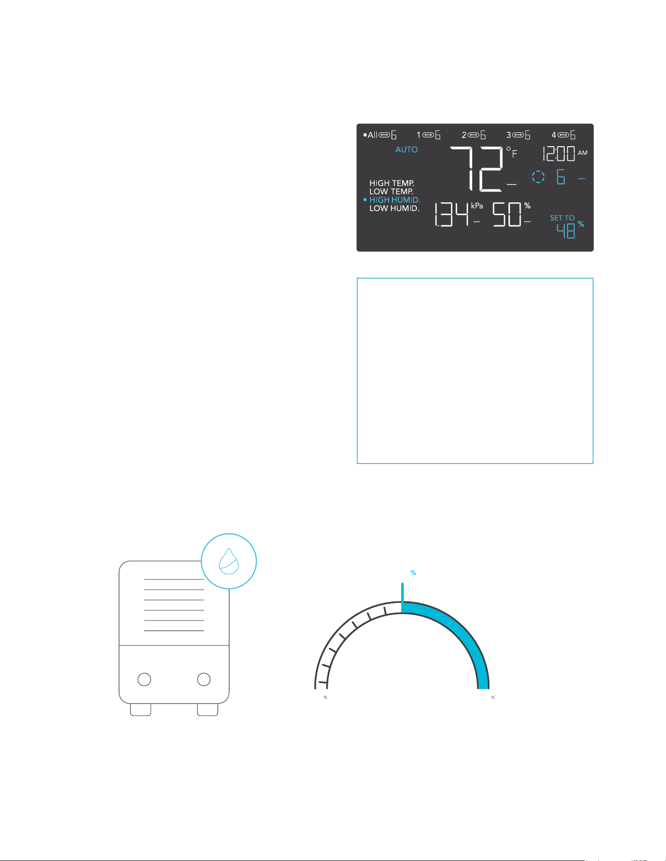
AUTO MODE (HIGH HUMIDITY TRIGGER)
Pressing the up or down button sets the high
humidity trigger. The devices will activate if the
probe’s reading meets or exceeds this threshold.
Once triggered, the devices will gradually ramp up
to the level set in ON mode. If the probe’s reading
falls below this trigger point, the devices will
gradually slow down to a stop or at the level set in
OFF mode.
You may set this trigger below the low humidity
trigger to create a specific range in which the
devices are active.
This is typically used with devices like
dehumidifiers to help lower the humidity when
it gets too humid. For example, if you set a high
humidity trigger of 48%, then your device will
activate when the humidity rises to 48% or higher,
and turn off when it falls below 48%. Products
shown here may still be in development.
Any of the four trigger points can
activate while you are in AUTO
Mode, even if you are viewing
another trigger point. Please set
a trigger point to OFF if not in
use, by holding down the up and
down button. If there is a level
set in OFF Mode other than zero,
the devices will run at that level
when triggered to turn o.
CONTROLLER 69 PRO
ON
HIGH HUMIDITY
TRIGGER POINT
OFF
LESS HUMID MORE HUMID
48
0
100
95
PROGRAMMING
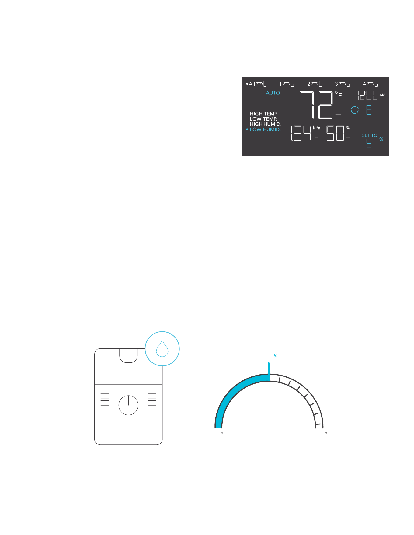
AUTO MODE (LOW HUMIDITY TRIGGER)
Pressing the up or down button sets the low
humidity trigger. The devices will activate if the
probe’s reading meets or falls below this threshold.
Once triggered, the devices will gradually ramp up
to the level set in ON mode. If the probe’s reading
rises above this trigger point, the devices will
gradually slow down to a stop or at the level set in
OFF Mode.
You may set this trigger above the high humidity
trigger to create a range in which the devices
are active.
This is typically used with devices like humidifiers
to help raise the humidity when it gets too dry. For
example, if you set a low humidity trigger of 57%,
then your device will activate when the humidity
falls to 57% or lower, and turn off when it rises
above 57%. Products shown here may still be
in development.
Any of the four trigger points can
activate while you are in AUTO
Mode, even if you are viewing
another trigger point. Please set
a trigger point to OFF if not in
use, by holding down the up and
down button. If there is a level
set in OFF Mode other than zero,
the devices will run at that level
when triggered to turn o.
CONTROLLER 69 PRO
LOW HUMIDITY
TRIGGER POINT
ON OFF
LESS HUMID MORE HUMID
57
0
100
96
PROGRAMMING
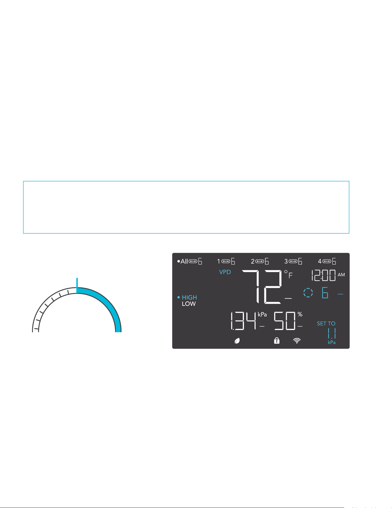
VPD MODE (HIGH VPD TRIGGER)
Pressing the up or down button sets the high VPD trigger. The devices will activate if the probe’s
reading meets or exceeds this threshold.
Once triggered, the devices will gradually ramp up to the level set in ON mode. If the probe’s
reading falls below this trigger point, the devices will gradually slow down to a stop or at the level
set in OFF mode.
You may set this trigger below the low VPD trigger to create a specific range in which the
devices are active.
CONTROLLER 69 PRO
Either of the two trigger points can activate while you are in VPD Mode, even if you are
viewing another trigger point. Set a trigger point to OFF if not in use, by holding down the
up and down button. If there is a level set in OFF Mode other than zero the devices will
run at that level when triggered to turn o.
ONOFF
TRIGGER POINT
HIGH VPD
HIGH VPDLOW VPD
0
kPa
9.9
kPa
1.1kPa
97
PROGRAMMING
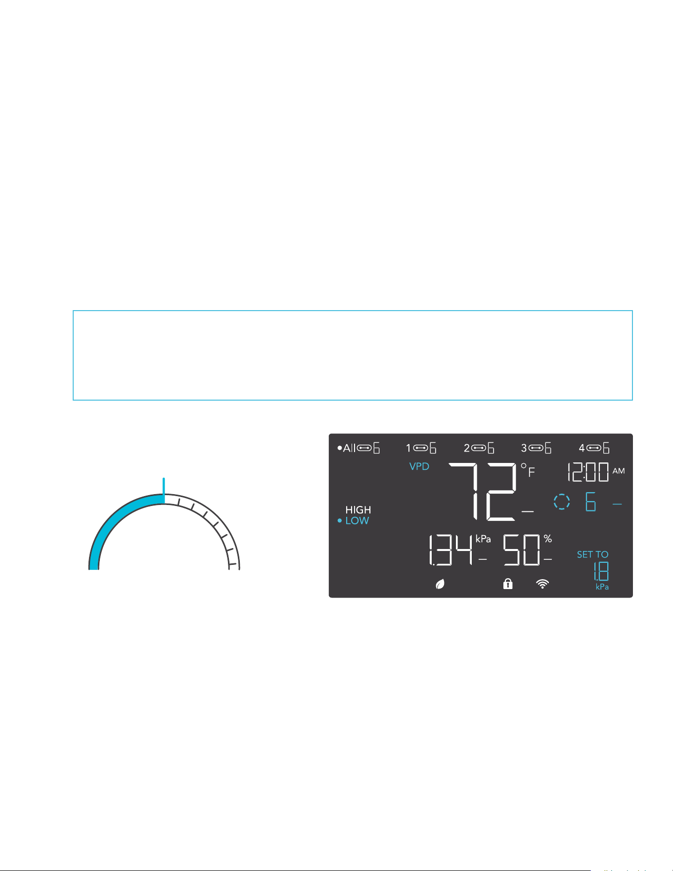
VPD MODE (LOW VPD TRIGGER)
Pressing the up or down button sets the low VPD trigger. The devices will activate if the probe’s
reading meets or falls below this threshold.
Once triggered, the devices will gradually ramp up to the level set in ON mode. If the probe’s
reading rises above this trigger point, the devices will gradually slow down to a stop or at the
level set in OFF Mode.
You may set this trigger above the high VPD trigger to create a range in which the devices
are active.
Either of the two trigger points can activate while you are in VPD Mode, even if you are
viewing another trigger point. Set a trigger point to OFF if not in use, by holding down the
up and down button. If there is a level set in OFF Mode other than zero the devices will
run at that level when triggered to turn o.
CONTROLLER 69 PRO
ON OFF
TRIGGER POINT
LOW VPD
1.8kPa
HIGH VPDLOW VPD
0
kPa
9.9
kPa
98
PROGRAMMING
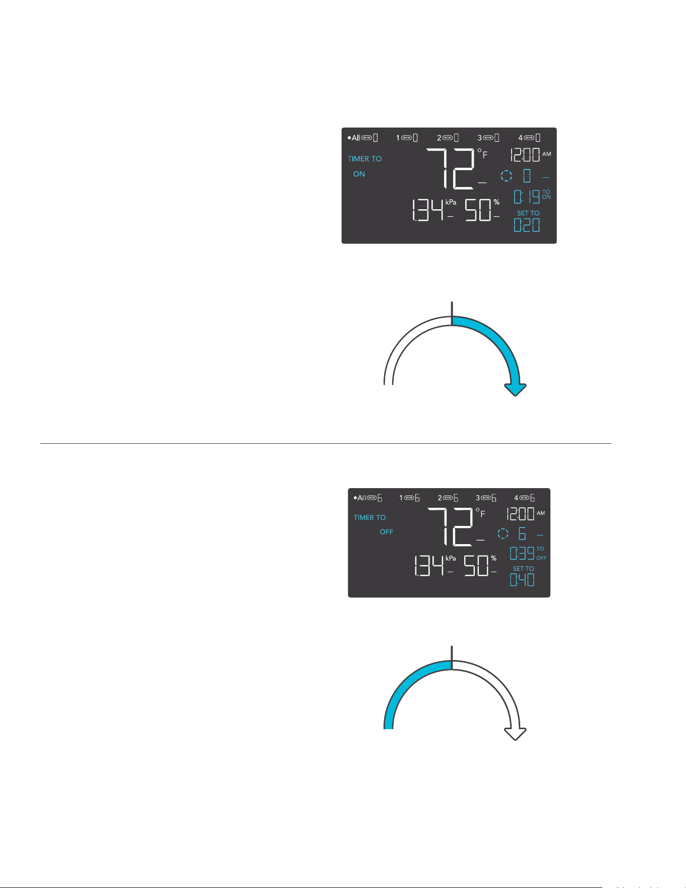
TIMER TO ON MODE
Pressing the up or down button sets a
countdown time. During the countdown,
your device will be set to OFF. Once the
timer ends, your device will trigger to turn
on. If there is a level set in OFF Mode,
the devices will run at that level during
the countdown and when triggered to
turn off.
The countdown will begin if no buttons
are pressed for 5 seconds. The time left
on the countdown is shown on the lower
right corner of the display above the
setting. Leaving the timer mode while the
countdown is running will pause it until
you return to this mode.
TIMER TO OFF MODE
Pressing the up or down button sets a
countdown time. During the countdown,
your device will be set to ON. Once the
timer ends, your device will trigger to turn
off. If there is a level set in OFF Mode,
the devices will run at that level after the
end of the countdown.
The countdown will begin if no buttons
are pressed for 5 seconds. The time left
on the countdown is shown on the lower
right corner of the display above the
setting. Leaving the timer mode while the
countdown is running will pause it until
you return to this mode.
TIMER TO ON
(COUNTDOWN END POINT)
START
2
0
m
i
n
.
t
o
O
N
D
e
v
i
c
e
O
N
START
TIMER TO OFF
(COUNTDOWN END POINT)
4
0
m
i
n
.
t
o
O
F
F
D
e
v
i
c
e
O
F
F
CONTROLLER 69 PRO
99
PROGRAMMING
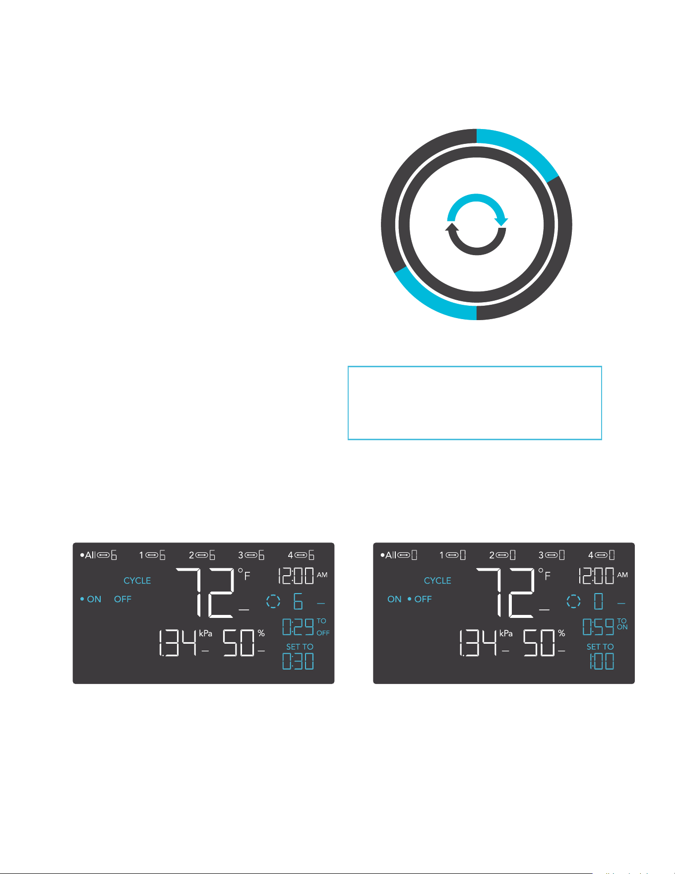
CYCLE MODE (ON AND OFF)
Set an on duration and an off duration for
the devices to cycle through continuously.
Press the up or down button to first set a
duration for the devices to activate. Then
press the mode button again and set a
duration for the devices to deactivate.
When the devices are activated, they will
run at the level set in ON Mode. When
the devices are deactivated, they will run
at the level set in OFF Mode.
The countdown will begin if no buttons
are pressed for 5 seconds. The time left
on the countdown before the next ON
or OFF phase is displayed below the
current level. Leaving the cycle mode
while the countdown is running will pause
it until you return to this mode.
30min.
1hr.
30min.
1hr.
O
F
F
O
N
O
N
O
F
F
CONTROLLER 69 PRO
If there is a level set in OFF Mode
other than zero, the devices will run
at that level when triggered to turn off.
100
PROGRAMMING
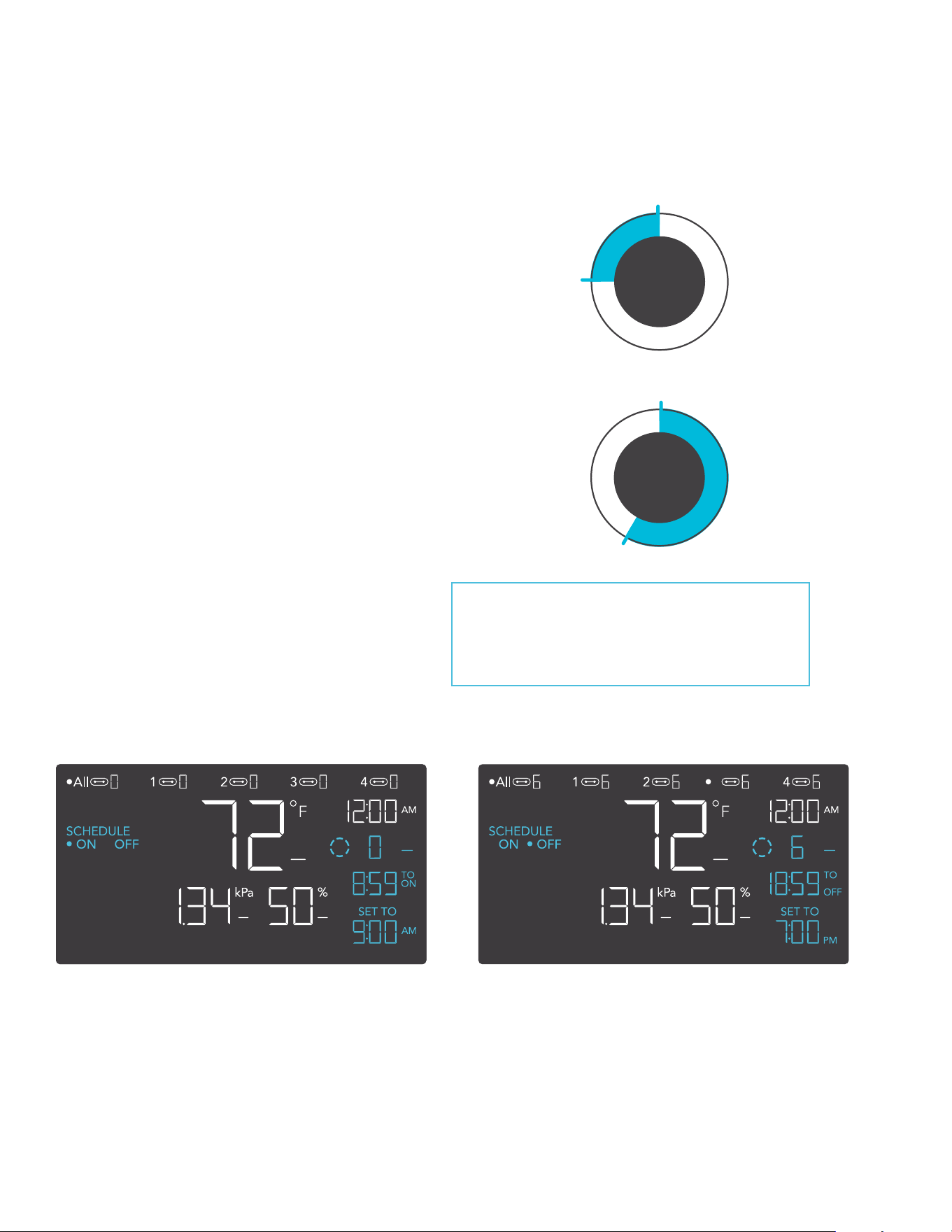
SCHEDULE MODE (ON AND OFF)
Sets an on clock-time and an off clock-time
schedule for the devices to follow daily.
Press the up or down button to first set up
an on clock-time to trigger ON mode, then
press the mode button to set an off clock-
time to trigger OFF mode. Please be sure
to set the current clock time under settings.
When the devices are triggered to
activate, they will run at the level set in ON
Mode. When the devices are triggered to
deactivate, they will run at the level set in
OFF Mode.
The countdown will begin if no buttons are
pressed for 5 seconds. The time left on
the countdown before the next on or off
phase is displayed below the current level.
The devices will not follow this schedule
if you leave this mode. If you re-enter the
Schedule Mode, they will continue to follow
the latest schedule you have set.
7:00
12:00
PM
O
F
F
O
N
PM
ON
AM
O
F
F
O
N
12:00
9:00
CONTROLLER 69 PRO
If there is a level set in OFF Mode
other than zero, the devices will run
at that level when triggered to turn off.
101
PROGRAMMING
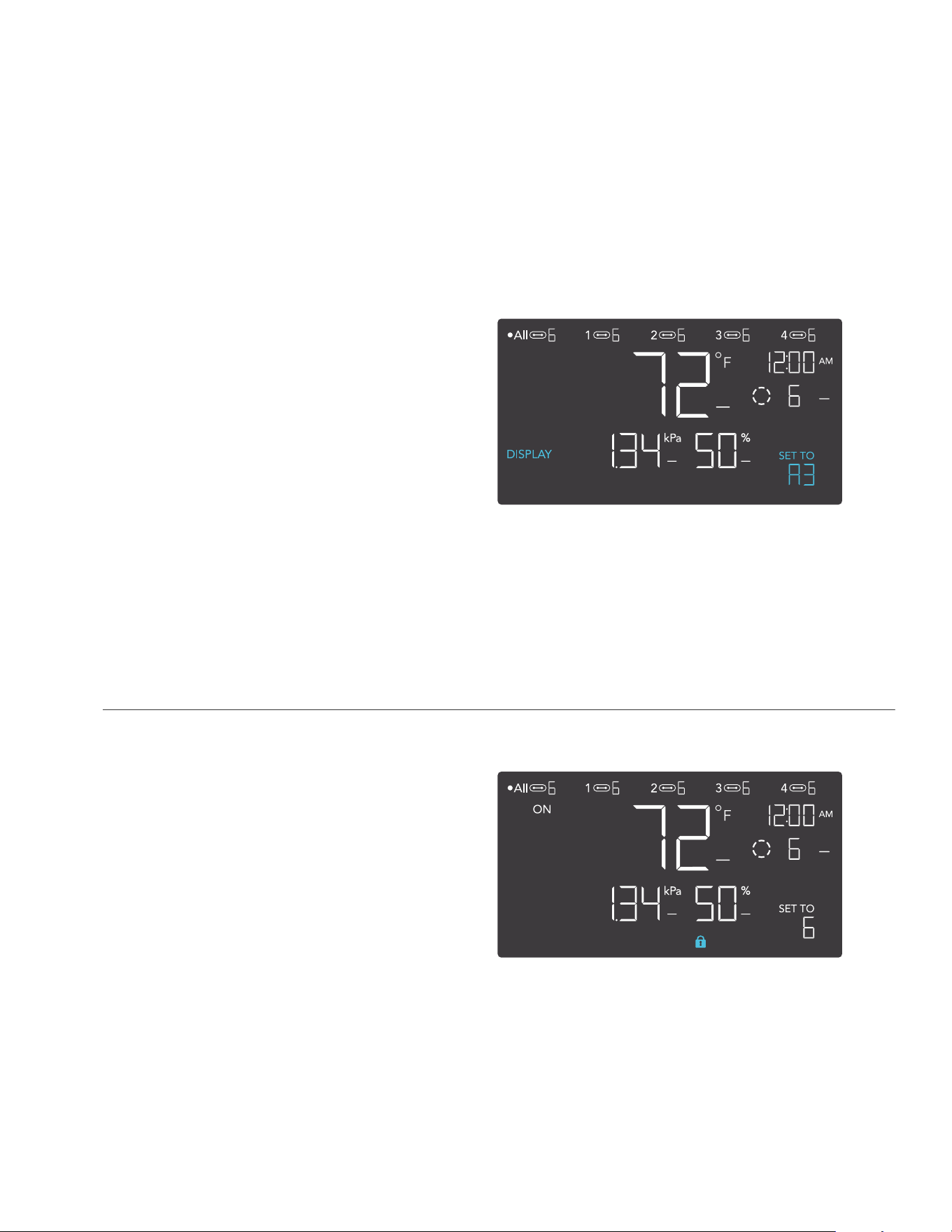
DISPLAY SETTING
Adjusts the display brightness and
auto-dimming. Press the up or down
button to cycle through levels 1, 2, 3, A2
and A3; 3 being the highest brightness
setting, while 1 is the lowest. In settings
1, 2 and 3, the display will stay at that
brightness level and will not automatically
dim the display.
A2 and A3 will set the brightness level
at 2 and 3, respectively, and will dim
down the brightness to level 1 when the
controller is not being used after
15 seconds.
CONTROLLER SETTINGS
Pressing the setting button will cycle through the controller’s available settings: DISPLAY,
CLOCK, °F / °C, CALIB. T° / H% / kPa, TRANS. T° / H% / kPa, BUFF. T° / H% / kPa, and
LEAF OFFSET.
TOGGLING THE DISPLAY
Lock the controller by holding the
setting button.
Press the setting button to turn the
display off. Pressing the setting button
again will turn the display back on.
Programs will still run in the background
while the LCD screen is off.
CONTROLLER 69 PRO
102
PROGRAMMING
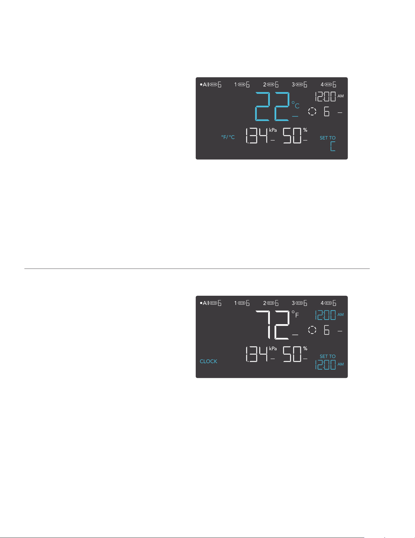
CLOCK SETTING
Adjusts the current clock time. Press
the up or down button to increase or
decrease the time. Once you cycle
through 12:00 each time, the units will
automatically change to AM or PM. The
clock time is located at the top right
corner of the display.
°F/°C SETTING
Changes the displayed units to
Fahrenheit or Celsius. Press the up or
down button to cycle through F and C. All
displayed units will automatically convert
when adjusting this setting.
CONTROLLER 69 PRO
103
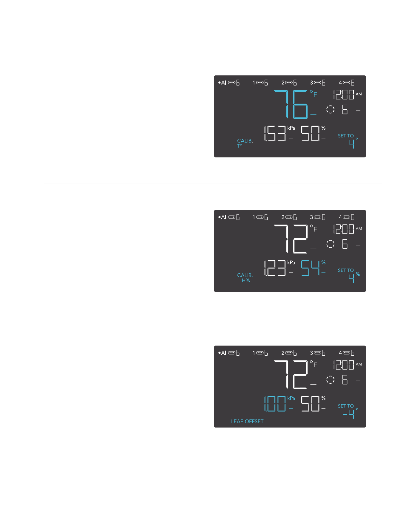
CALIBRATION TEMPERATURE SETTING
Adjusts the temperature reading the sensor
probe is measuring. Press the up or down
button to increase or decrease the data
figure in 2°F (or 1°C) increments. The
calibration cycle ranges from -20°F to 20°F
(or -10°C to 10°C) and will be applied to the
sensor probe’s measurements.
CALIBRATION HUMIDITY SETTING
Adjusts the relative humidity reading the
sensor probe is measuring. Press the up
or down button to increase or decrease
the data figure in 1% increments. The
calibration cycle ranges from -10% to
10% and will be applied to the sensor
probe’s measurements.
PROGRAMMING
CONTROLLER 69 PRO
CALIBRATION LEAF OFFSET SETTING
Adjusts the VPD reading the sensor probe
is measuring. Press the up or down button
to increase or decrease the data figure
in 1° increments. The calibration cycle
ranges from -20°F to 20°F (or -10°C to
10°C) and will be applied to the sensor
probe’s measurements.
104
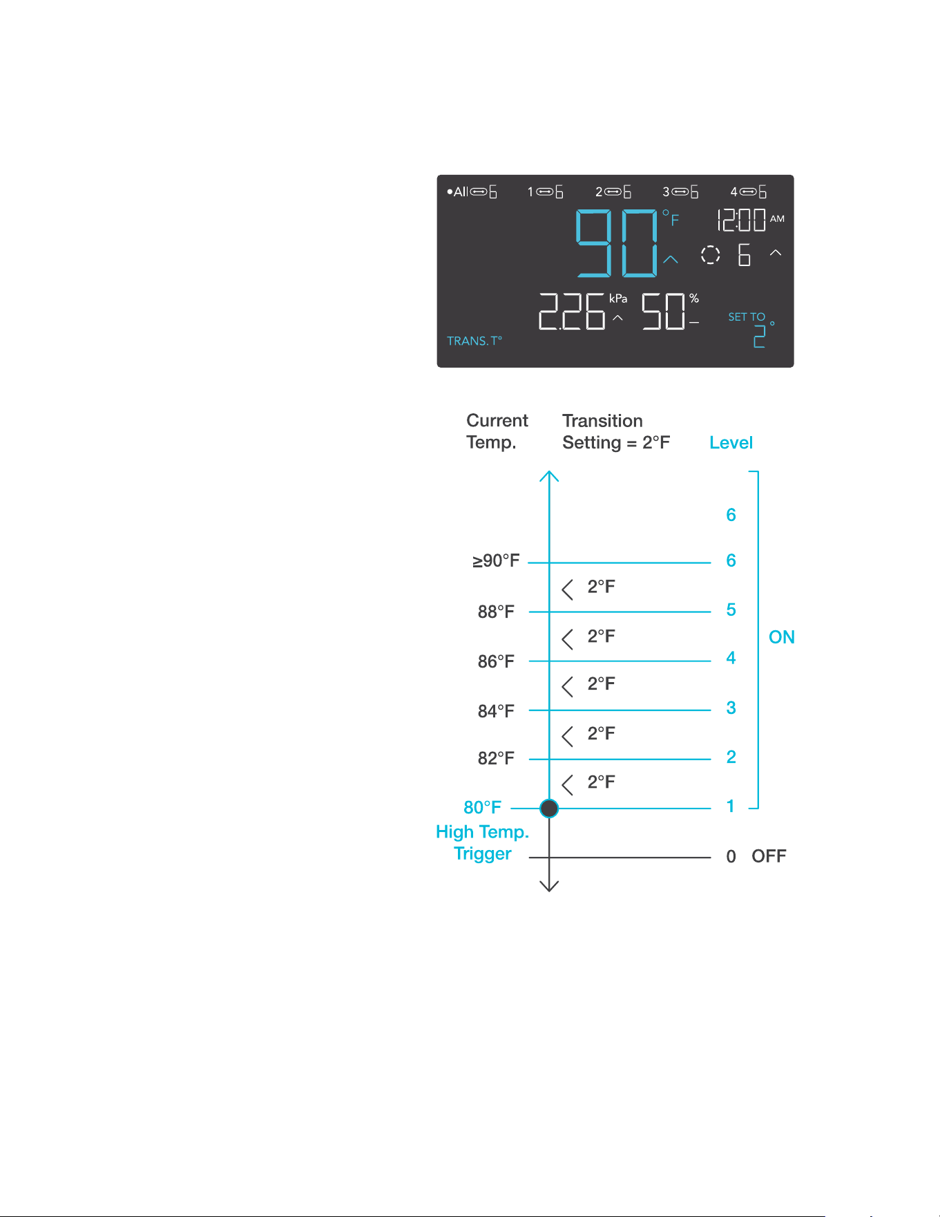
TRANSITION TEMPERATURE SETTING
Adjusts how gradually your device will
shift between levels when triggered ON
by the AUTO Mode’s temperature trigger.
This will determine how much the probe
temperature needs to increase to step up
to the next level setting.
The higher the transition setting is, the
wider the temperature gap is between
levels. The lower the transition setting
is, the smaller the temperature gap is
between levels. If this figure is set to zero,
your device will jump to your maximum
level when triggered ON.
Press the up or down button to set a
transition threshold between 0°F and
20°F (0°C and 10°C). When the sensor
temperature first reaches or crosses the
temperature trigger point, the level will
increase by one (exiting OFF Mode).
Each time the threshold level is crossed,
the level will ramp up by one until it
reaches the level set in ON Mode.
EXAMPLE
In this example, your high temperature
trigger is set at 80°F, the OFF Mode level
is 0, and the ON Mode level is 6. If the
transition threshold is set to 0°F, then
once the sensor temperature reaches or
exceeds 80°F, the devices will trigger to
run at level 6. However, if the transition
threshold is set to 2°F, then the devices
will trigger to run at level 1 when the
temperature reaches or exceeds 80°F.
It will then ramp up to level 2 when the
temperature reaches or exceeds 82°F,
level 3 at 84°F, etc. From 90°F on, it will
run at level 6, the level set in ON Mode.
PROGRAMMING
CONTROLLER 69 PRO
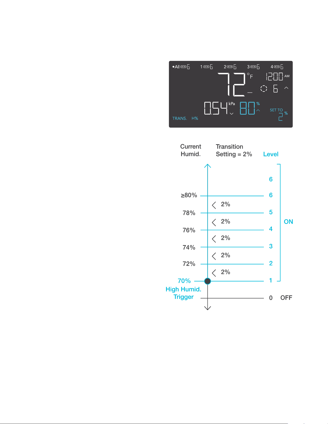
105
TRANSITION HUMIDITY SETTING
Adjusts how gradually your device will
shift between levels when triggered ON
by the AUTO Mode’s humidity trigger.
This will determine how much the probe
humidity needs to increase to step up to
the next level setting.
The higher the transition setting is, the
wider the humidity gap is between levels.
The lower the transition setting is, the
smaller the humidity gap is between
levels. If this figure is set to zero, your
device will jump to your maximum level
when triggered ON.
Press the up or down button to set a
transition threshold between 0% and
10%. When the sensor humidity first
reaches or crosses the humidity trigger
point, the level will increase by one
(exiting OFF Mode). Each time the
threshold level is crossed, the level will
ramp up by one until it reaches the level
set in ON Mode.
EXAMPLE
In this example, your high humidity
trigger is set at 70%, the OFF Mode level
is 0, and the ON Mode level is 6. If the
transition threshold is set to 0%, once the
sensor humidity reaches or exceeds 70%
then the devices will trigger to run at level
7. However, if the transition threshold is
set to 2%, then the devices will trigger to
run at level 1 when it reaches or exceeds
70%. It will then step up to level 2 when
reaching or exceeding 72%, level 3 at
74%, etc. From 80% on, it will run at level
6, the level set in ON Mode.
PROGRAMMING
CONTROLLER 69 PRO
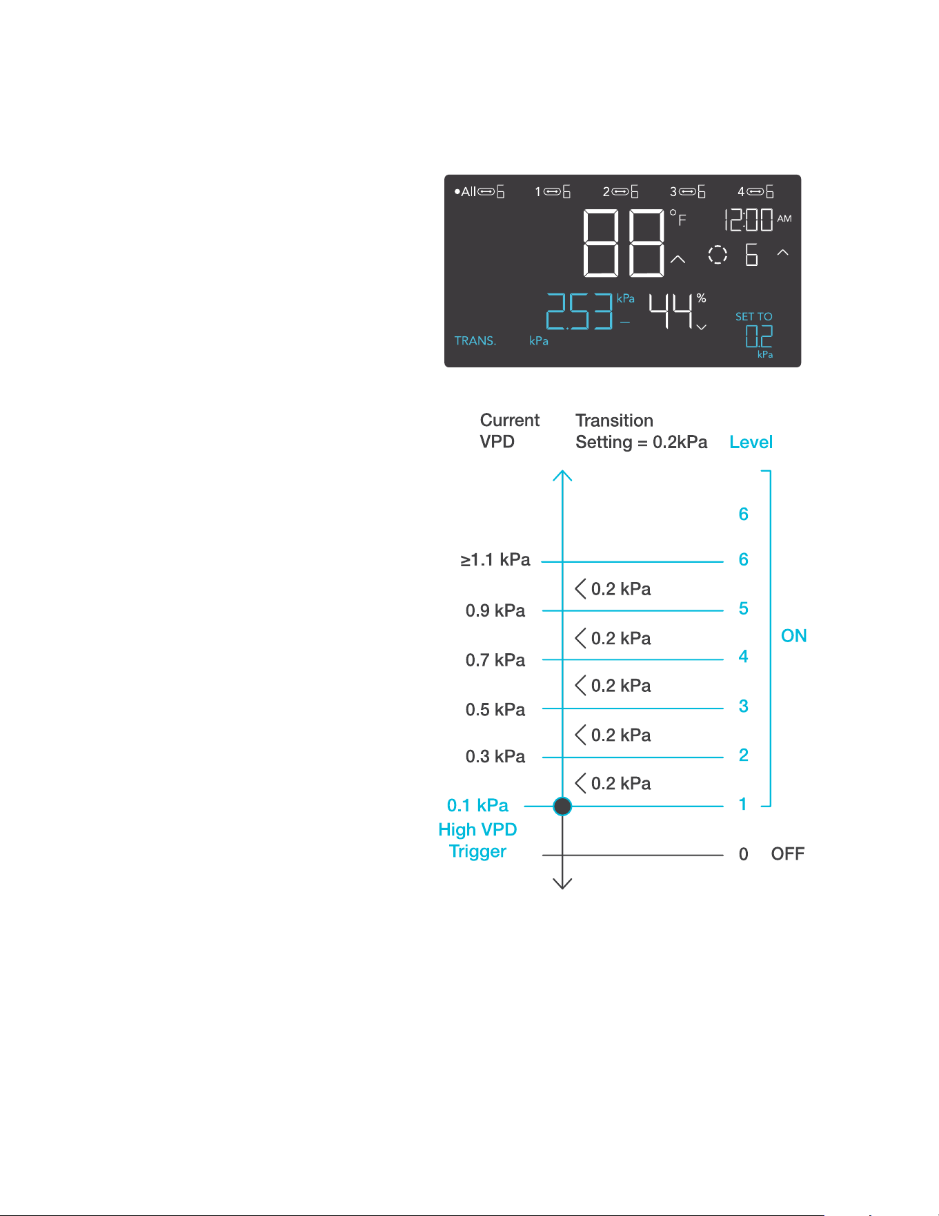
106
TRANSITION VPD SETTING
Adjusts how gradually your device will shift
between levels when triggered ON by the
VPD trigger. This will determine how much
the probe VPD needs to increase to step
up to the next level setting.
The higher the transition setting is, the
wider the VPD gap is between levels. The
lower the transition setting is, the smaller
the VPD gap is between levels. If this figure
is set to zero, your device will jump to your
maximum level when triggered ON.
Press the up or down button to set a
transition threshold between 0.1 kPa
and 1.0 kPa. When the sensor VPD first
reaches or crosses the VPD trigger point,
the level will increase by one (exiting OFF
Mode). Each time the threshold level is
crossed, the level will ramp up by one until
it reaches the level set in ON Mode.
EXAMPLE
In this example, your high VPD trigger is
set at 0.1 kPa, the OFF Mode level is 0,
and the ON Mode level is 6. If the transition
threshold is set to 0 kPa, then once the
sensor temperature reaches or exceeds
0.1 kPa, the devices will trigger to run at
level 6. However, if the transition threshold
is set to 0.2 kPa, then the devices will
trigger to run at level 1 when the VPD
reaches or exceeds 0.1 kPa. It will then
ramp up to level 2 when the VPD reaches
or crosses 0.3 kPa, level 3 at 0.5 kPa, etc.
From 1.1 kPa on, it will run at level 6, the
level set in ON Mode.
PROGRAMMING
CONTROLLER 69 PRO
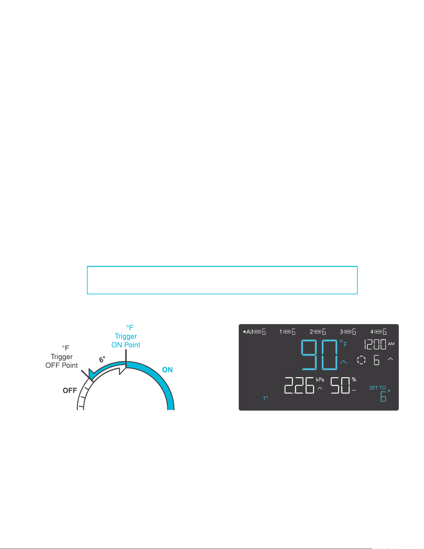
107
BUFFER TEMPERATURE SETTING
The buffer figure will create a trigger-off point below your set trigger point to prevent your device
from shutting off too quickly. Press the up or down button to cycle through buffer range from 0°F
to 8°F (or 0°C to 4°C).
In high temperature triggers, your device will turn on, only turning off when the temperature falls
below your buffer setting.
In low temperature triggers, your device will turn on, only turning off when the temperature rises
above your set buffer setting.
EXAMPLE
For example, if you had set a High Temperature Trigger at 89°F and set a Temperature Buffer at
6°F. Then your device will trigger on when it meets or rises above 89°F, and only trigger off when
it falls below 83°F. The 83°F figure is obtained by taking your High Temperature Trigger of 89°F
and subtracting your Temperature Buffer of 6°F.
PROGRAMMING
CONTROLLER 69 PRO
89
83
BUFF.
This setting will only appear in ports connected with outlet adapters.

108
PROGRAMMING
BUFFER HUMIDITY SETTING
The buffer figure will create a trigger-off point below your set trigger point to prevent your device
from shutting off too quickly. Press the up or down button to cycle through buffer range from 0%
to 10%.
In high humidity triggers, your device will turn on, only turning off when the humidity falls below
your buffer setting.
In low humidity triggers, your device will turn on, only turning off when the humidity rises above
your set buffer setting.
EXAMPLE
For example, if you had set a High Humidity Trigger at 49% and set a Humidity Buffer at 4%.
Then your device will trigger on when it meets or rises above 49%, and only trigger off when it
falls below 45%. The 45% figure is obtained by taking your High Humidity Trigger of 49% and
subtracting your Humidity Buffer of 4%.
CONTROLLER 69 PRO
BUFF.
49
45
This setting will only appear in ports connected with outlet adapters.
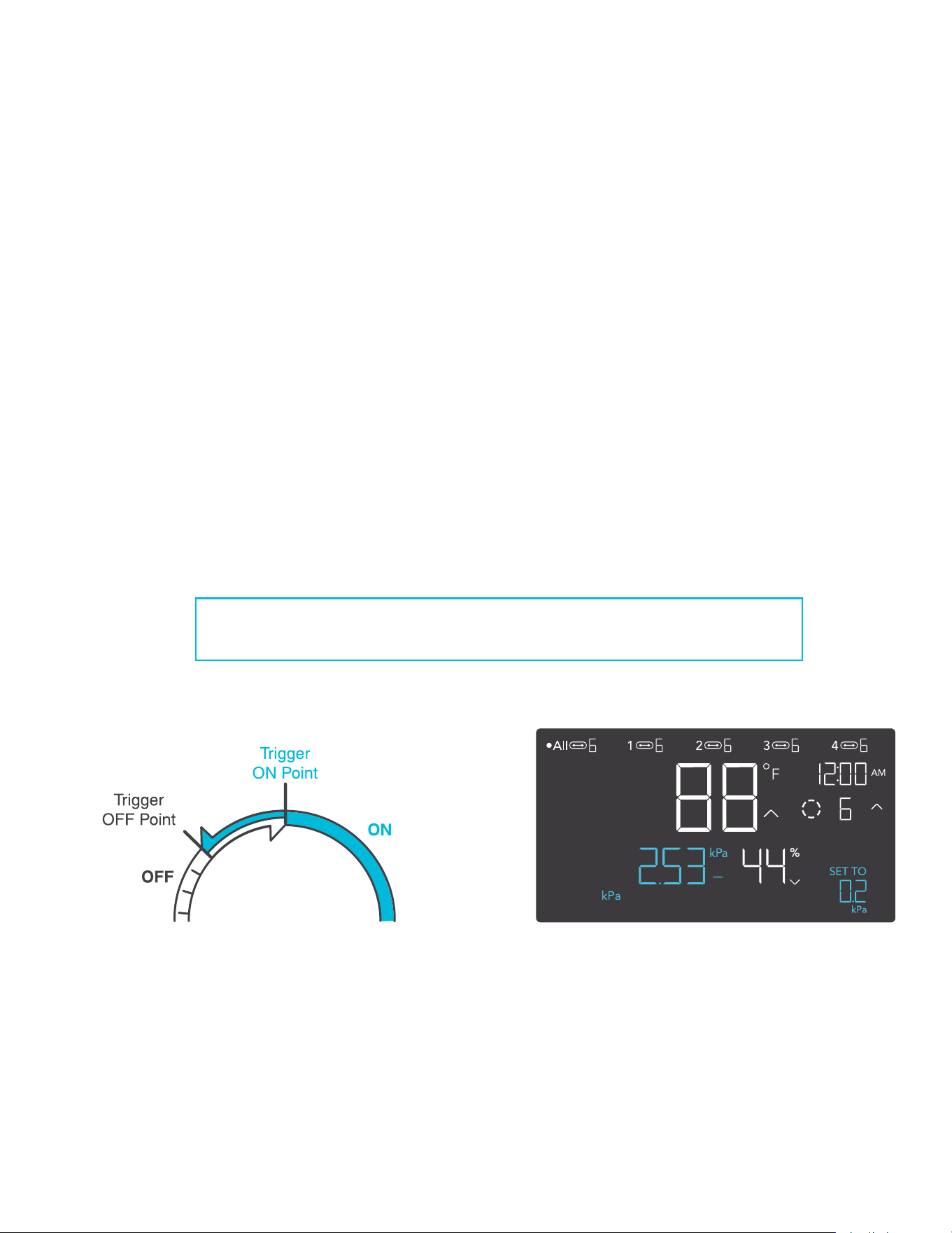
109
BUFFER VPD SETTING
The buffer figure will create a trigger-off point below your set trigger point to prevent your device
from shutting off too quickly. Press the up or down button to cycle through buffer range from 0.1
kPa and 1.0 kPa.
In high VPD triggers, your device will turn on, only turning off when the VPD falls below your
buffer setting.
In low VPD triggers, your device will turn on, only turning off when the VPD rises above your set
buffer setting.
EXAMPLE
For example, if you had set a High VPD Trigger at 2.51 kPa and set a VPD Buffer at 0.2 kPa.
Then your device will trigger on when it meets or rises above 2.51 kPa, and only trigger off when
it falls below 2.31 kPa%. The 2.51 kPa figure is obtained by taking your High VPD Trigger of
2.51% and subtracting your VPD Buffer of 0.2 kPa.
PROGRAMMING
CONTROLLER 69 PRO
BUFF.
2.51
kPa
2.31
kPa
0.2
kPa
This setting will only appear in ports connected with outlet adapters.
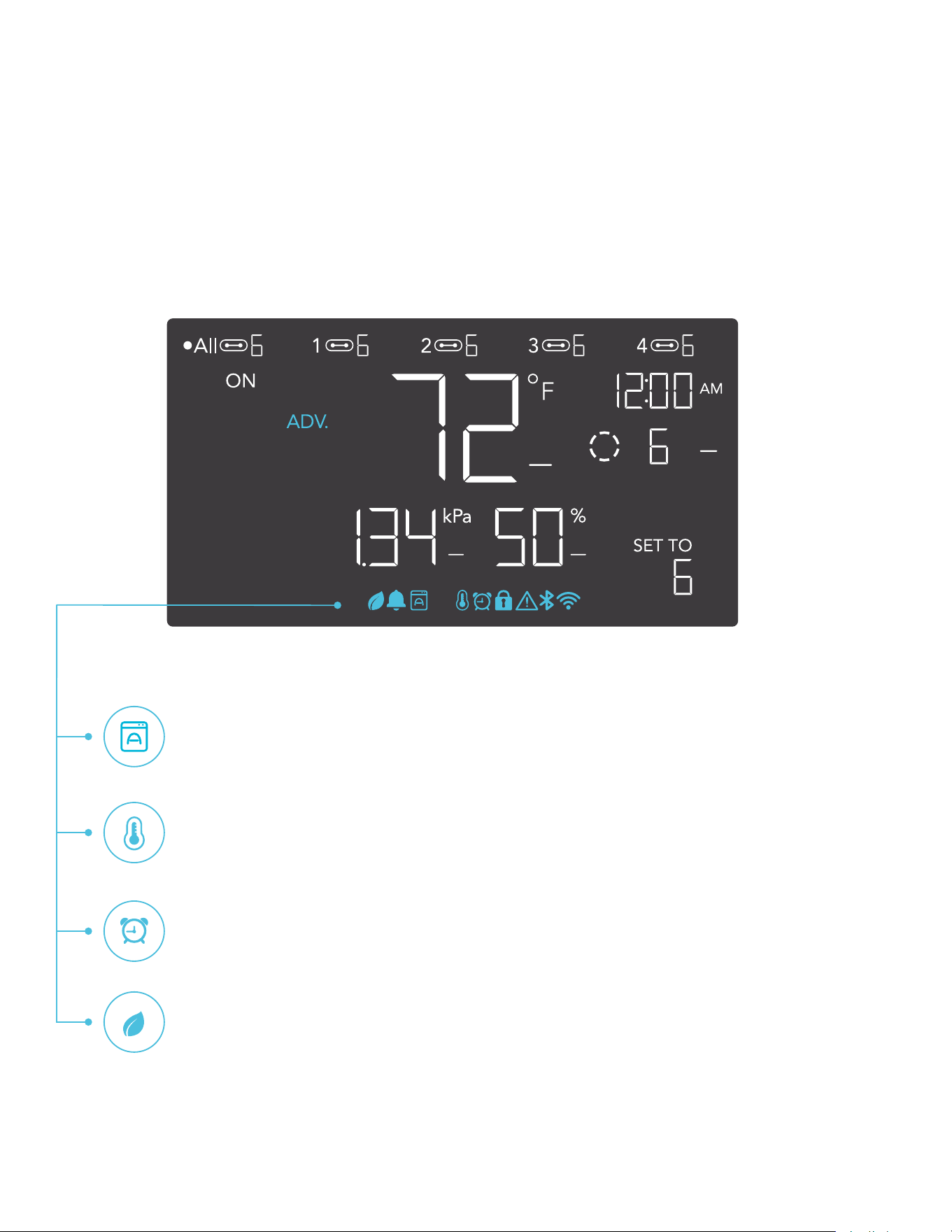
110
PROGRAMMING
ALERT ICONS
The alert icons are displayed at the top of the screen. Icons may flash when the controller
signals an alert to notify you of any triggered function or alarm.
ADVANCE PROGRAMMING
Displays when an advance program set in the app is active. "ADV." will appear
and override the controller if an automation program is in use.
AUTO MODE ALERT
Flashes whenever any of the auto mode triggers (high temperature, low
temperature, high humidity, or low humidity) activate your devices.
TIMER ALERT
Flashes when a countdown has completed for TIMER TO ON, TIMER TO OFF,
CYCLE, or SCHEDULE Mode.
VPD ALERT
Flashes whenever either VPD mode triggers (high VPD or low VPD) activate
your devices.
CONTROLLER 69 PRO
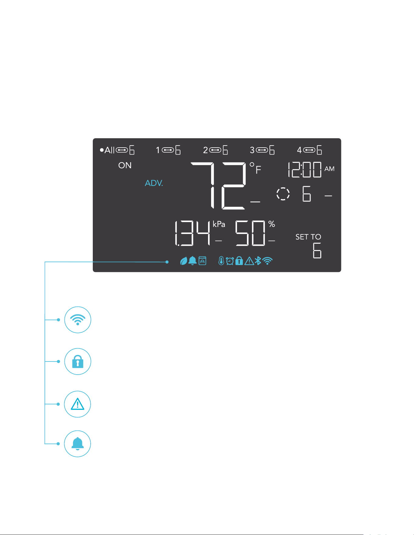
111
PROGRAMMING
DISPLAY LOCK ALERT
Displays when you lock the controller. The icon will flash and beep if you attempt
to adjust the controller while it is still locked.
ALERT
Flashes and beeps with an alert whenever a plugged-in device experiences
interference to its functioning. Check your devices for possible issues.
WI-FI
Appears when the physical controller is connected to the app via Wi-Fi.
ALARM
Flashes and beeps with an alert if the temperature/humidity/VPD meet the
trigger point set in the app.
CONTROLLER 69 PRO
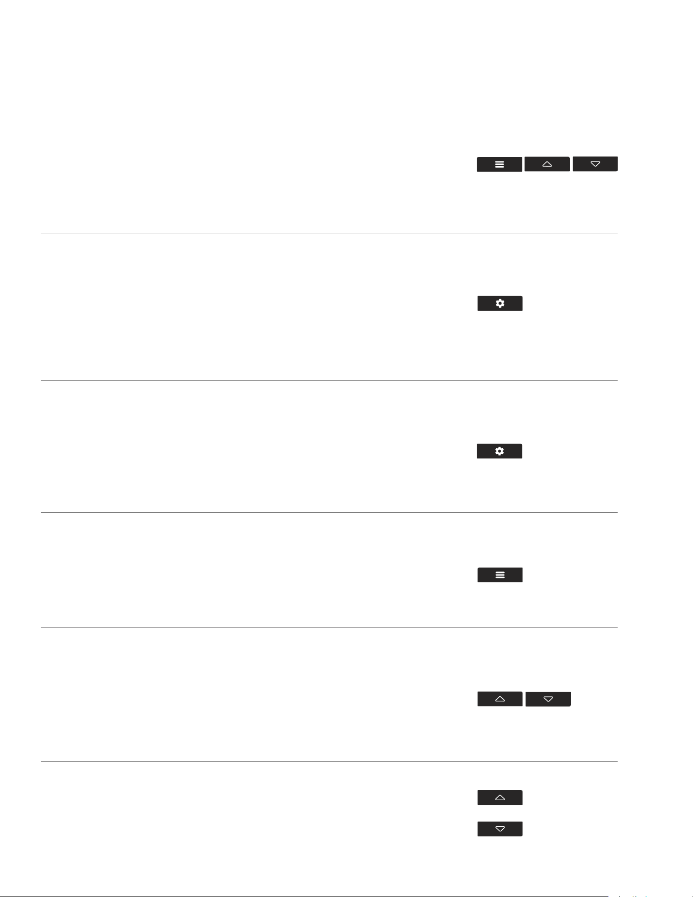
112
JUMP TO OFF MODE
Holding the mode button for 3 seconds while in any mode
or setting will automatically jump to OFF Mode. This
function is disabled if the controller is locked.
FACTORY RESET
Holding the mode, up, and down buttons together for 5
seconds will reset your controller and restore factory
settings. This clears all user parameters in each controller
mode and setting.
CONTROLLER LOCK
Holding the setting button will lock the controller in
your current mode. While your controller is locked, no
parameters may be adjusted, nor will you be able to
switch modes. Holding the setting button again will unlock
the controller.
HIDE SCREEN
Lock the controller so no settings can be adjusted. See
above. Then press the setting button to turn the display off.
Pressing it again will turn the display back on. Programs
will still run in the background while the LCD screen is off.
PRESS +
RESET TO OFF/DEFAULT
Holding the up and down buttons together for 2 seconds
will reset the value of your current mode or controller
setting to OFF/Default. Pressing either the up or down
button will return to the previous value.
AUTO INCREASING OR DECREASING
Holding the up or down button will increase or decrease
the user setting automatically until you release them.
HOLD +
OTHER SETTINGS
HOLD +
HOLD +
HOLD +
HOLD +
HOLD +
CONTROLLER 69 PRO
113
Download the AC Infinity app from the App
Store or Play Store by searching “AC Infinity”.
Open the AC Infinity app and follow the
instructions on page 114-120 to pair
your controller with the app.
DOWNLOAD THE APP
21
THE AC INFINITY APP
The AC Infinity app enables you to connect with the next generation of our intelligent controllers,
giving you access to advance programs and environmental data.
QUICK TIP FOR EASY ACCESS
Open the smart phone camera and scan the QR code below to download the AC Infinity app.
Please visit our website at www.acinfinity.com for more information on the AC Infinity app.
Please note: The AC Infinity App’s appearance and features are subject to change, and please refer
to our website/QR for the latest instructions.
CONTROLLER 69 PRO
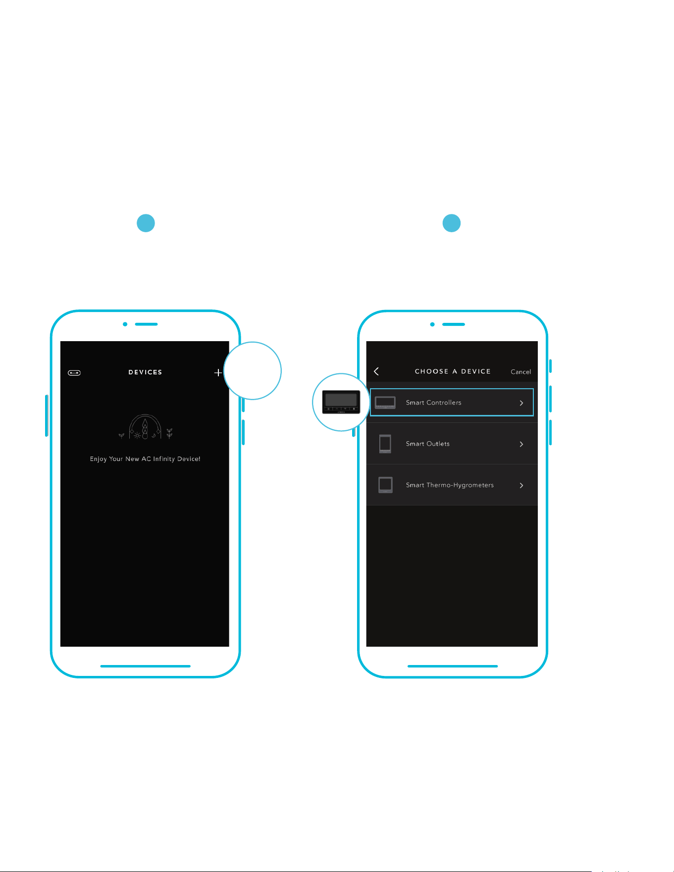
114
Tap on the “+” tab to
add your smart device.
Tap on the “Smart Controllers” tab.
Please note: Bluetooth must be enabled on your mobile device before starting the pairing process.
ADD A DEVICE: BLUETOOTH
21
SETUP AND PAIRING
Power your device on before pairing your controller with the app. Logging in or creating an
account beforehand will expedite the pairing process. Have your Wi-Fi network’s name and
password ready.
CONTROLLER 69 PRO
+
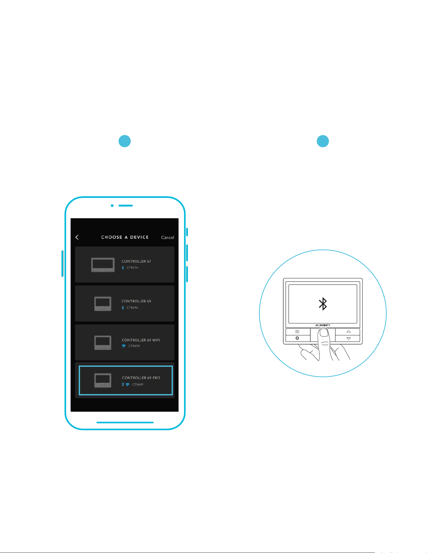
115
ADD A DEVICE: BLUETOOTH
Hold the port button for 5 seconds
to activate Bluetooth. Wait for the
Bluetooth icon to start flashing on
your controller’s screen.
Select CONTROLLER 69 PRO.
3
4
CONTROLLER 69 PRO
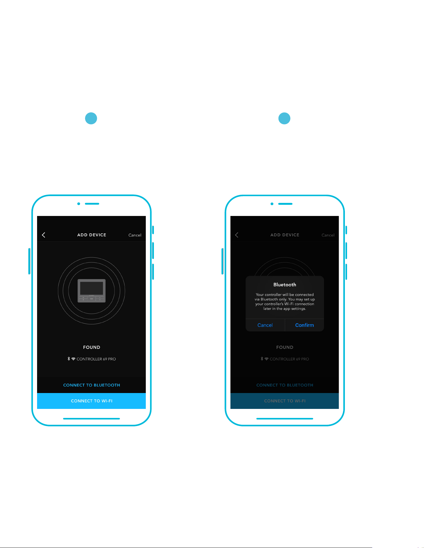
116
ADD A DEVICE: BLUETOOTH
Connect using Bluetooth. To
connect using Wi-Fi, skip to step 8.
Connecting with Bluetooth will
disable Wi-Fi functionality. Go
to the app settings page to re-
enable and connect using Wi-Fi.
5
6
When pairing the app around multiple controllers, move your mobile device closer to your desired controller.
CONTROLLER 69 PRO
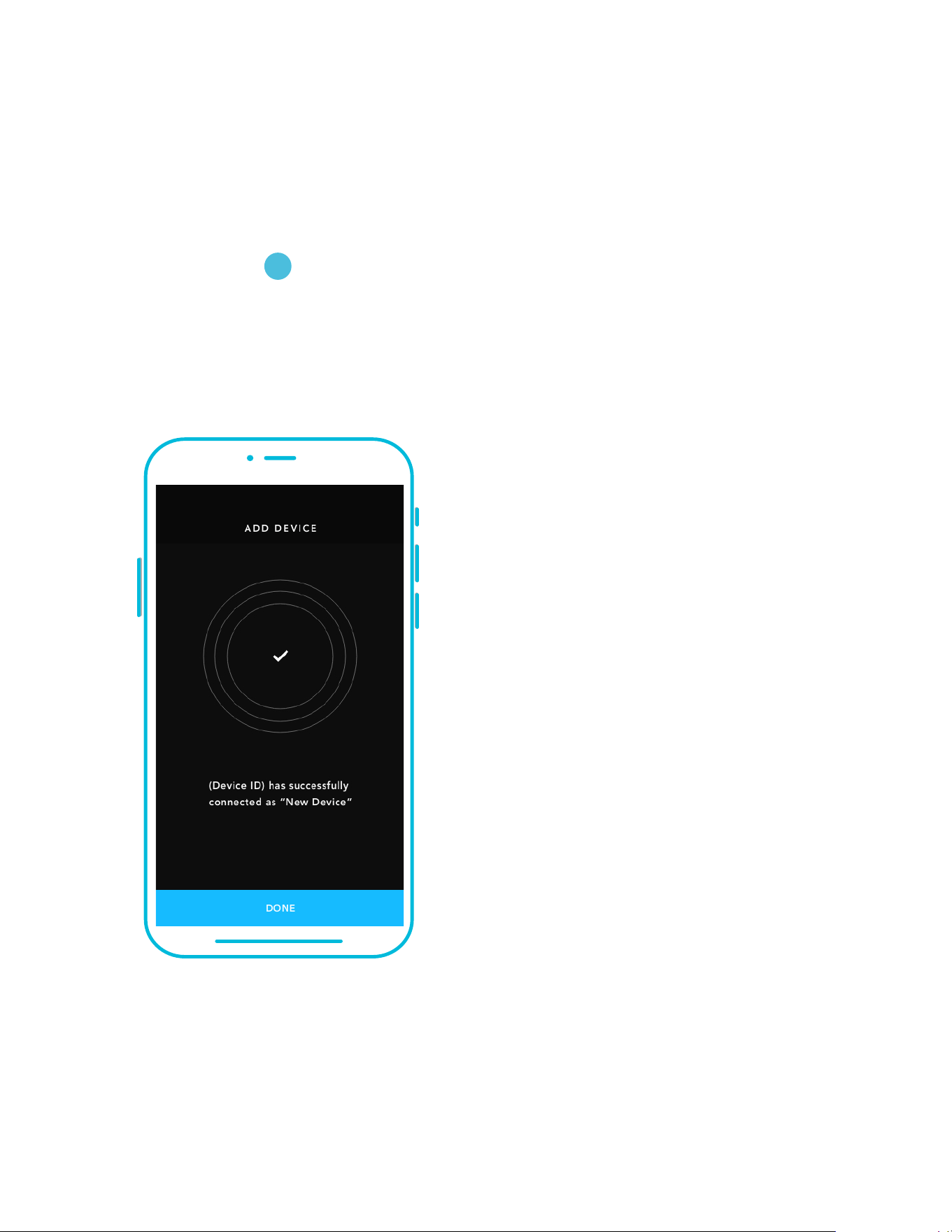
117
ADD A DEVICE: BLUETOOTH
Tap the DONE button to complete
the pairing process.
CONTROLLER 69 PRO
7
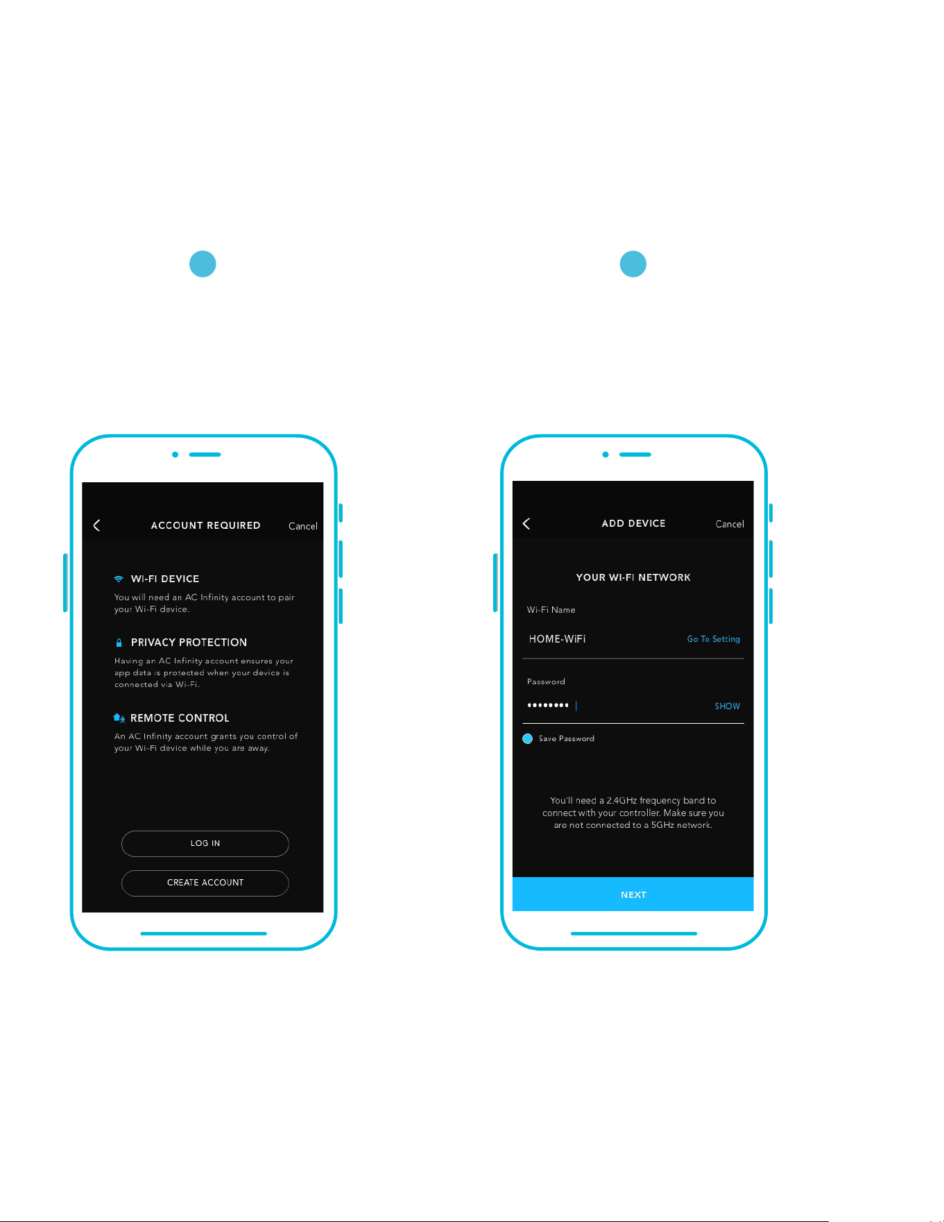
118
ADD A DEVICE: WI-FI
Repeat steps 1-5. Log in or create
an account to continue.
Enter your Wi-Fi network’s
password. You may also connect
to an alternate 2.4 GHz router*.
8
9
When pairing the app around multiple controllers, move your mobile device closer to your desired controller.
CONTROLLER 69 PRO
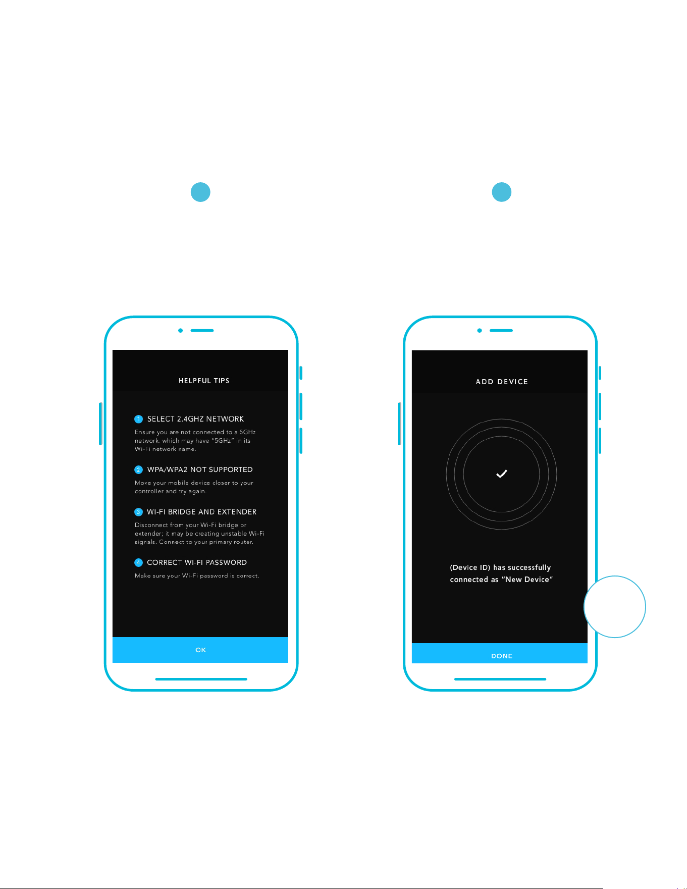
119
ADD A DEVICE: WI-FI
Follow these tips if the pairing
process is unsuccessful.
Tap the DONE button to complete
the pairing process.
*This controller is only compatible with 2.4 GHz frequency band routers. When connecting using Wi-Fi, make sure your mobile
device is not connected to a 5 GHz frequency band network.
10
11
CONTROLLER 69 PRO
DONE
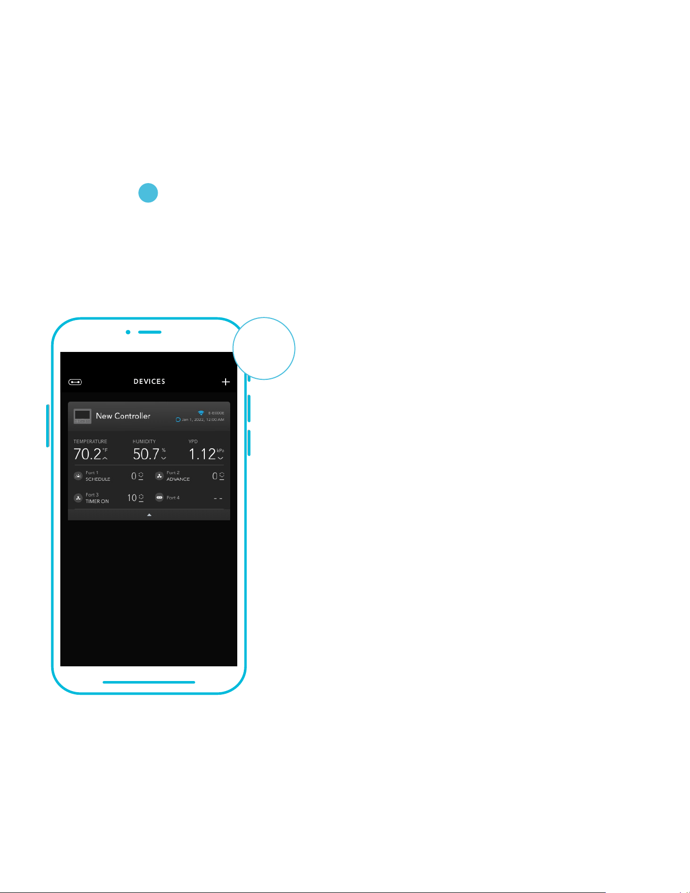
120
ADD A DEVICE: WI-FI
Your controller will appear in your
smart device with a unique ID.
G-G000G
12
CONTROLLER 69 PRO

121
FREQUENTLY ASKED QUESTIONS
What devices are compatible with the CONTROLLER 69 PRO?
All AC Infinity devices that contain a UIS connector are compatible. If your AC Infinity device
has a 4-pin Molex connector and an EC-Motor, it may still be compatible with the use of an
UIS adapter to convert its connector to fit with the controller.
Q:
A:
Where is the best place to position the sensor probe?
Place the sensor probe as close as possible to the hottest or most humid spot in your space.
Q:
A:
What does “level” refer to in the controller and app?
The level represents the intensity the device is running at. This is represented by a digit
0 to 10. Zero means the device is off, and 10 represents its running at its maximum. For
fan devices, the level would be referring to its speed. For light devices, the level would be
referring to its brightness. Note that on and off devices do not have a level setting.
Q:
A:
Do I need to remove the plastic cap from the probe?
Yes. You will need to remove the plastic cap so the probe can accurately read
climate conditions.
Q:
A:
Why is my device is not turning off when the programming is triggering it to be off?
The figure set in OFF Mode determines the device’s level when it’s triggered to be OFF in all
other modes. Set this figure to zero if you want the device to turn off when triggered OFF.
If this is occurring in AUTO Mode, check the points of your high and low triggers, which can
all activate concurrently. Turn off any triggers that are not in use. If you are using the app,
check to see if any ADVANCE programming is active, which can override any
control programming.
Q:
A:
Why does my device not run or run at a low level when the programming is triggering
it to be on?
The figure set in ON Mode determines the device’s level when it’s triggered to be ON in all
other modes. Make sure this figure is not set to zero or the device will not run when triggered
to be ON.
If this is occurring in AUTO Mode, check the points of your high and low triggers, which can
all activate concurrently. Turn off any triggers that are not in use. If you are using the app,
check to see if any ADVANCE programming is active, which can override any
control programming.
Q:
A:
CONTROLLER 69 PRO
122
Can I connect different sized fans to the same controller?
Please refer to pages 86-87 for details on adding more fan units.
Q:
A:
Will I be able to use this controller with my own devices?
The CONTROLLER 69 PRO is only compatible with AC Infinity fans that use EC-motors.
Q:
A:
Does the controller retain its settings after power is shut off?
Yes. If the controller's power is cut off and is powered on afterwards, your settings will remain.
Q:
A:
My controller isn't pairing with the app. How do I fix this?
If the pairing process isn't successful, turn off your Bluetooth and re-enable it to try again.
When starting the pairing process around multiple Bluetooth controllers, move your smart
device closer to the controller you wish to connect the app with.
Q:
A:
FREQUENTLY ASKED QUESTIONS
How do I stop my device from turning on and off too quickly in AUTO MODE?
The figure set in the TRANSITION under SETTINGS will determine how the device ramps
up in levels when triggered to run in AUTO MODE. Set a transition threshold X. For every
multiple of X that has surpassed your trigger point, the device will increase by one level. The
lower the transition threshold is set to, the easier it will be for the device to ramp up in levels.
If set to zero, the device will jump to the max set speed without ramping when triggered.
This may cause the device to turn on and off quickly if the climate fluctuates back and forth.
Increase the transition threshold number to help smooth out the transitions. Check the points
of your high and low triggers, which can all activate concurrently. Turn off any triggers that
are not in use.
Q:
A:
How do I set a minimum speed for constant ventilation, that would ramp up
when triggered?
If a fan device is connected, the figure set in OFF MODE determines the fan speed when it’s
triggered to be OFF in all other modes. When the fan isn’t triggered ON, it will be considered
OFF and so it will run at that minimum speed continuously. Once triggered ON, it will change
its speed to the figure set under ON MODE.
Q:
A:
CONTROLLER 69 PRO

123
Why does the app ask me for location permissions?
The app requires location permissions to find the relative position of your smart controller
and communicate with existing Bluetooth devices already paired with the app. All Android
devices prior to system version 12.0 will require location permissions to be turned on for the
Bluetooth scan to be successful.
Q:
A:
CONTROLLER 69 PRO
FREQUENTLY ASKED QUESTIONS
Why do the port’s level digits on the screen occasionally flash when I unplug a device?
The controller may have received electronic interference during the disconnection. To fix this,
completely cut off power from the controller by unplugging all connected devices. Then plug
them back into their previous ports and resume normal use.
Q:
A:

124
WARRANTY
This warranty program is our commitment to you, the product sold by AC Infinity will be free
from defects in manufacturing for a period of two years from the date of purchase. If a product is
found to have a defect in material or workmanship, we will take the appropriate actions defined
in this warranty to resolve any issues.
The warranty program applies to any order, purchase, receipt, or use of any products sold by AC
Infinity or our authorized dealerships. The program covers products that have become defective,
malfunctioned, or expressively if the product becomes unusable. The warranty program goes
into effect on the date of purchase. The program will expire two years from the date of purchase.
If your product becomes defective during that period, AC Infinity will replace your product with a
new one or issue you a full refund.
The warranty program does not cover abuse or misuse. This includes physical damage,
submersion of the product in water, incorrect Installation such as wrong voltage input,
and misuse for any reason other than intended purposes. AC Infinity is not responsible for
consequential loss or incidental damages of any nature caused by the product. We will not
warrant damage from normal wear such as scratches and dings.
Contact our dealers department at dealers@acinfinity.com or (626) 838-4656 for more
information about our dealers and distributors program. Contact our customer service
department at support@acinfinity.com or 626-923-6399 for product and warranty assistance.
Our business hours are Monday through Friday, 9:00 am to 5:00 pm PST.
If you run into any issues with this product, contact us and
we'll happily issue a replacement or a full refund!

COPYRIGHT © 2023 AC INFINITY INC. ALL RIGHTS RESERVED
No part of the materials including graphics or logos available in this booklet may be copied,
photocopied, reproduced, translated or reduced to any electronic medium or machine
readable form, in whole or in part, without specific permission from AC Infinity Inc.



www.acinnity.com