

Thank you for choosing AC Infinity. We are committed to product quality and
friendly customer service. If you have any questions or suggestions, please
don’t hesitate to contact us. Visit www.acinfinity.com and click contact for our
contact information.
WELCOME
EMAIL
support@acinfinity.com
WEB
www.acinfinity.com
LOCATION
Los Angeles, CA
3

MANUAL CODE AP2007X1
UPC-A
854759004044
854759004723
854759004006
854759004105
854759004068
854759004549
854759004372
854759004389
854759004945
819137020504
854759004396
854759004402
854759004730
PRODUCT
AIRPLATE S1
AIRPLATE S2
AIRPLATE S3
AIRPLATE S5
AIRPLATE S7
AIRPLATE S9
AIRPLATE T3
AIRPLATE T7
AIRPLATE T8
AIRPLATE T8 WHITE
AIRPLATE T9
CONTROLLER 2
CONTROLLER 8
MODEL
AI-CFS80BA
AI-APS2
AI-CFS120BA
AI-CFD80BA
AI-CFD120BA
AI-APS9
AI-APT3
AI-APT7
AI-APT8
AI-APT8-W
AI-APT9
AI-ATC
AI-TCD4
4

MANUAL INDEX
Company Contact ............................................................
Manual Index ...................................................................
Cabinet Cooling Guide .....................................................
Key Features ...................................................................
Product Contents .............................................................
Changing Airflow Direction ...............................................
Mounting ..........................................................................
Powering ..........................................................................
Connecting More Fans .....................................................
S-Series Controller ...........................................................
T-Series Controller Programming .....................................
Multizone Controller Programming ...................................
FAQ .................................................................................
Other AC Infinity Products ...............................................
Warranty ..........................................................................
Page 3
Page 5
Page 6
Page 7
Page 8
Page 9
Page 11
Page 14
Page 15
Page 16
Page 17
Page 23
Page 24
Page 25
Page 26
5
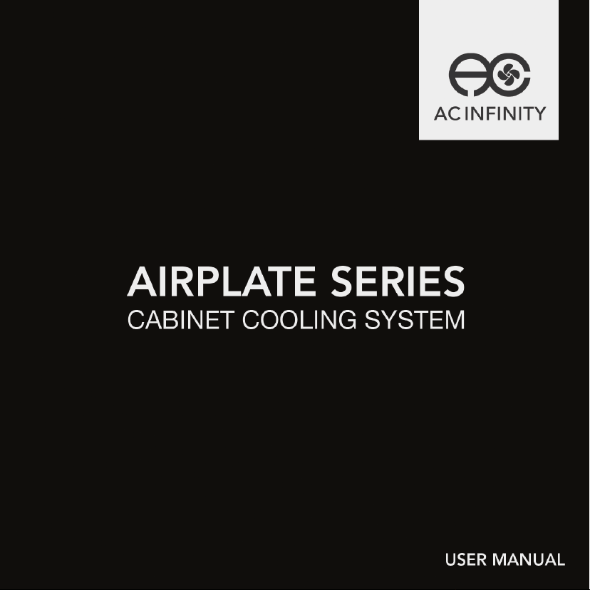
CABINET COOLING GUIDE
INTAKE AND EXHAUST
All cabinet fan systems should contain an
intake and an exhaust variable, which can
either be fans or ventilation holes. This is
required to balance the static pressures
between the inside and outside of the
cabinet.
FAN POSITIONING
Due to natural convection, warmer air
which is less dense than colder air will
rise on its own. It is ideal to position fans
near the top of the cabinet configured to
exhaust out the warmer air and position
fans near the bottom to push in colder air.
CFM REQUIREMENTS
A fan or set of fan’s CFM rating measures
the rate at which air flows into a space.
To obtain the required CFM rating, divide
the dimensions of a cabinet by 1728 to get
the cubic feet area then multiply by three
to account for various real world variables.
SIZE OF CABINET
L x W x H (inches)
1728
6
KEY FEATURES
ALUMINIUM FRAME
Features an aluminium frame
with a brushed black finish and
CNC machined corners.
DUAL BALL BEARINGS
Fans contain long-life ball
bearings rated at 67,000
hours. This feature also
enables fans to be mounted
in any direction.
PROTECTIVE BACK
Fans are enclosed in a hard
shell cover to prevent
intrusions.
SMART CONTROLLER
(Sold separately or included if the
T-SERIES was purchased)
LCD display enables temp
monitoring, thermal control,
speed control, alarms, and
SMART energy mode.
FAN EXPANSION PORTS
Each fan unit contains an USB
port to daisy chain additional
fan units. Up to six fans can
share the same power source.
7
THERMAL PROBE
The corded sensor probe
constructed of stainless
steel ensures an accurate
temperature reading.
AC INFINITY
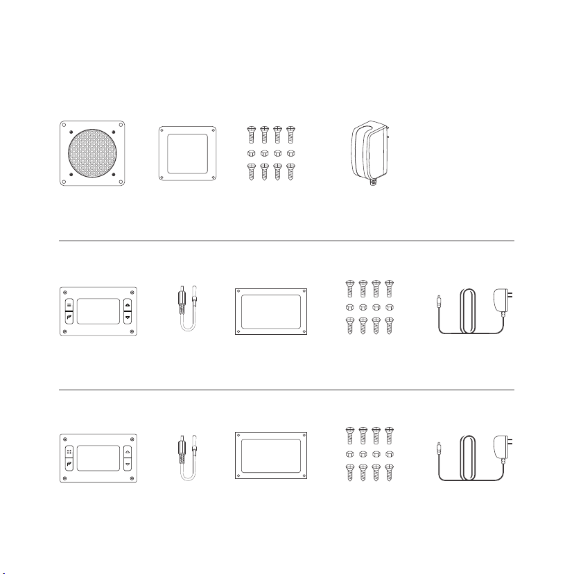
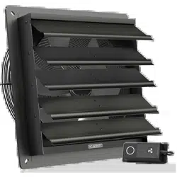
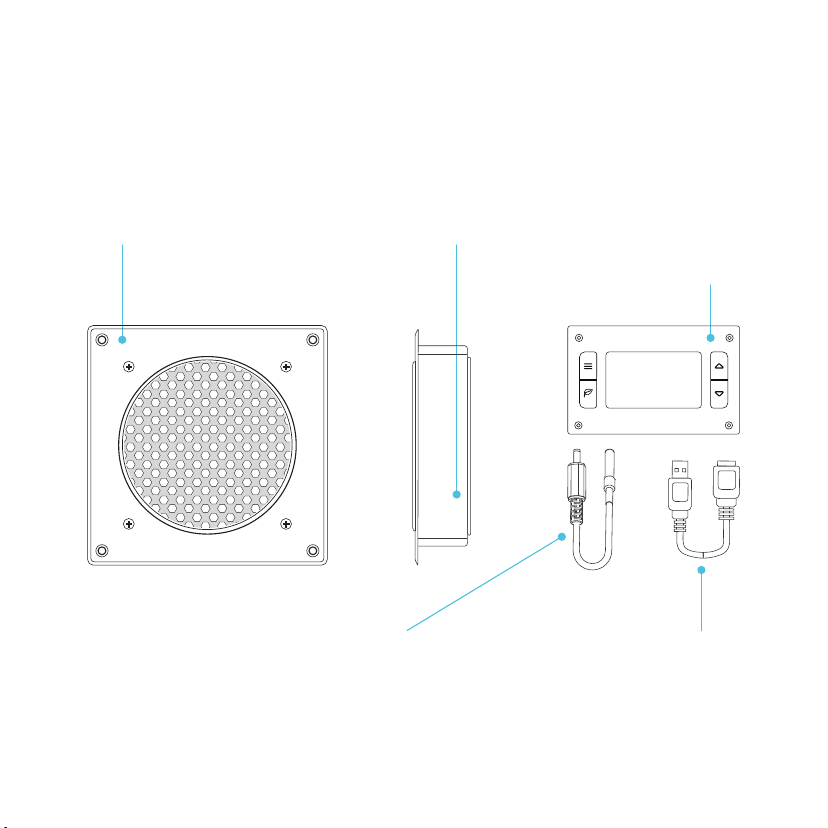
PRODUCT CONTENTS
S-SERIESS-SERIES
CABINET FAN
UNIT (x1)
PLASTIC
STENCIL (x1)
MOUNTING
SCREW SET (x4)
USB POWER
ADAPTER (x1)
8
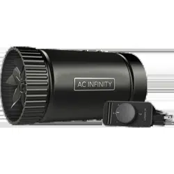
T-SERIES
AC INFINITY
THERMAL
CONTROLLER (x1)
THERMAL
PROBE (x1)
PLASTIC
STENCIL (x1)
MOUNTING
SCREW SET (x4)
USB POWER
ADAPTER (x1)
MULTIZONE CONTROLLER
(Sold Seperately)
THERMAL
CONTROLLER (x1)
THERMAL
PROBE (x4)
PLASTIC
STENCIL (x1)
MOUNTING
SCREW SET (x4)
USB POWER
ADAPTER (x1)
AC INFINITY
(Includes S-SERIES Fan Units)
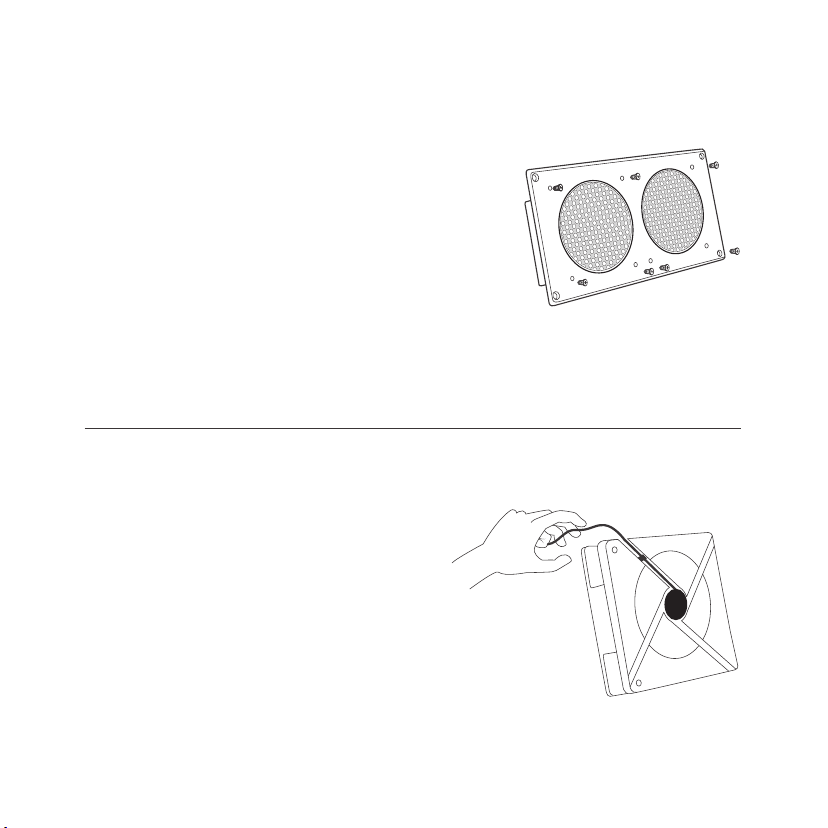
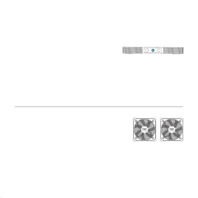
CHANGING FAN DIRECTION
STEP 1
The fans are currently drawing the air
out of the metal plate. To have the fans
blow air into the cabinet, use philips
screw driver to remove all the screws
from the front and backside of the unit.
Once completed, you should have an
aluminum fan and plastic cover. Each fan
will have eight screws, one grill, and one
fan guard per fan.
STEP 2
Identify the direction of the fans
airflow, which is towards the black
label at the center of the fan.
Then position the path of the fan’s
power cord so that it will run towards
the black label. Be prepared to slip the
cord through the plastic cover’s cord
gap.
9
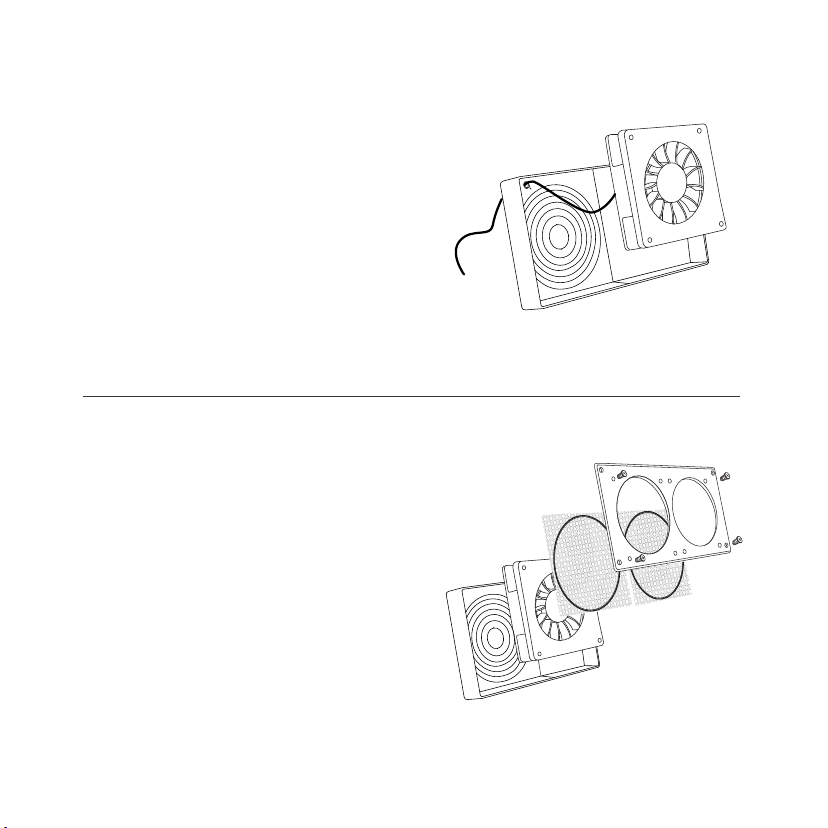
CHANGING FAN DIRECTION
STEP 3
Position the fan guard on the side of
the fan that has the black label. Screw
the plastic cover onto the fans with the
fan guard in between. Please make
sure the fan’s power cord slips through
the cord gap on the plastic cover.
STEP 4
Lastly, position the grill on the
opposite side which does not contain
a black label, for each fan. Then use
a Phillips screw driver to secure the
aluminum frame back onto the fans
with the grill in between.
10
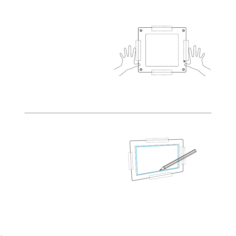
MOUNTING
STEP 1
Determine where you wish to mount
the fan and controller unit (if
purchased) on your cabinet or wall.
Position the stencils and apply tape
to the outer edges.
STEP 2
Use a pencil to outline the center
square and four outer screw holes on
the fan and thermo controller's stencils
(if purchased). Check for accuracy
before proceeding to the next step.
11
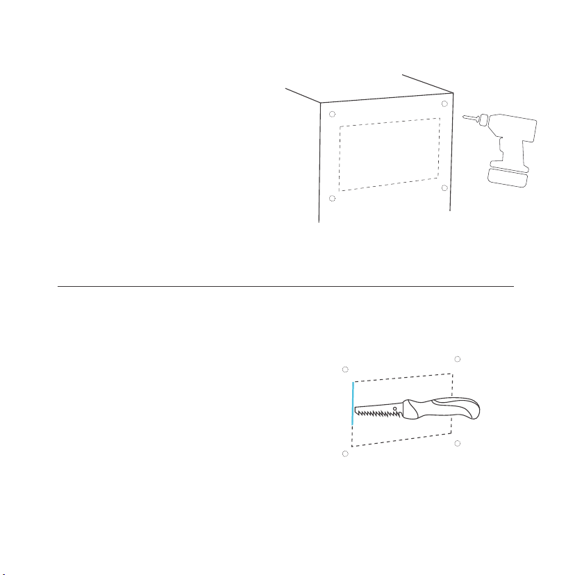
MOUNTING
STEP 3
Remove the plastic stencil and tape.
If you prefer machine screws instead
of wood screws to mount the fan and
controller, use a power drill to create
four screw holes. The Recommended
drill bit size is 10/64” to 14/64”.
STEP 4
Using a saw, cut out the center piece
as outlined by your markings from
step one. You may need to first drill a
hole at each of the corners to fit your
saw through. A power jigsaw may be
preferred for thicker wood.
12
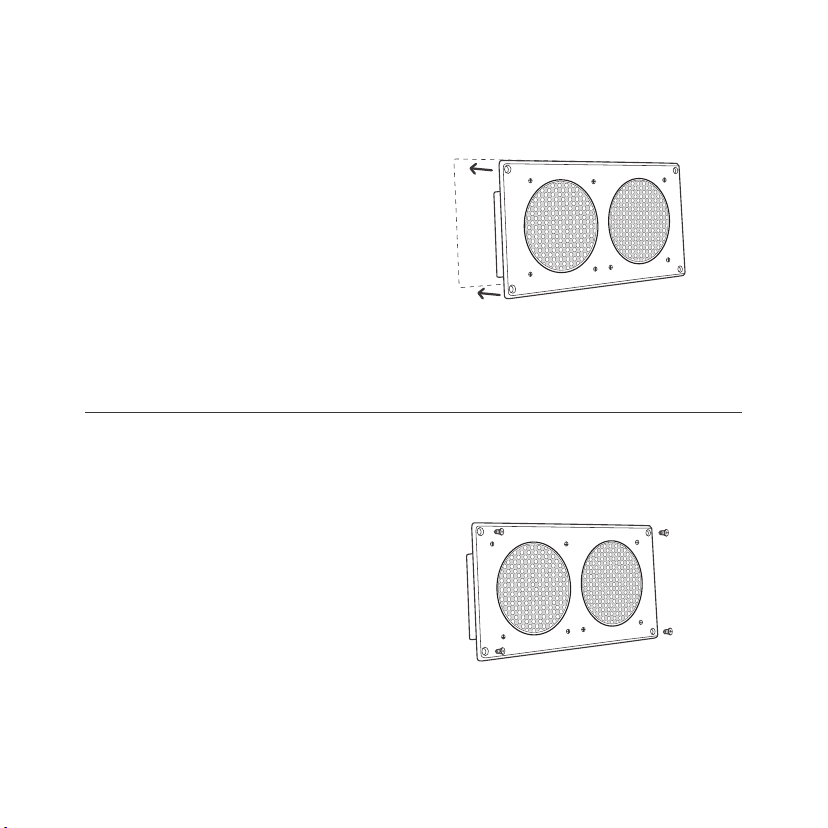
MOUNTING
STEP 5
Place the fan unit into the newly cut
square so that each screw hole is
properly aligned. Please make sure
the cut center hole is large enough
that the plastic backside of the fan
does not come into contact with the
cabinet. This is to minimize vibrations
which cause noise.
13
STEP 6
Using the four machine screws, secure
the fan unit’s frame onto the cabinet or
wall. Push each screw through their
corresponding hole located on the frame
and wall. The included wood screws can
also be used instead.Tighten the nuts on
the other side.
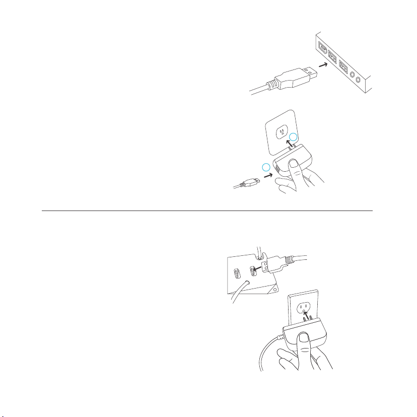
POWERING
S-SERIES
You can power the fan unit by
plugging the unit’s USB male
connector into a standard USB
port, or plugging the USB male
connector into the included
power adapter through an outlet.
Then plugging the adapter into
an outlet.
T-SERIES
Plug the fan unit’s USB plug into the
USB port located on the back of the
thermal control unit. Then plug the
wall adapter’s male connector into the
thermal controller’s power plug, also
located on the back. Lastly, plug the
power adapter into an outlet.
14
1
2
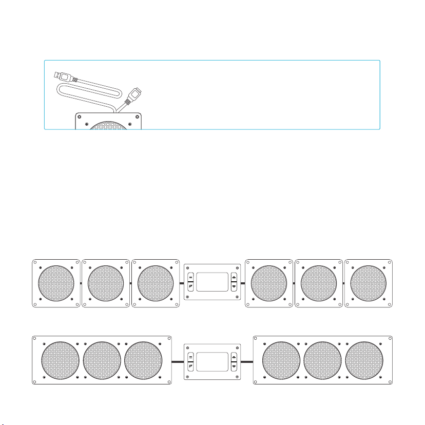
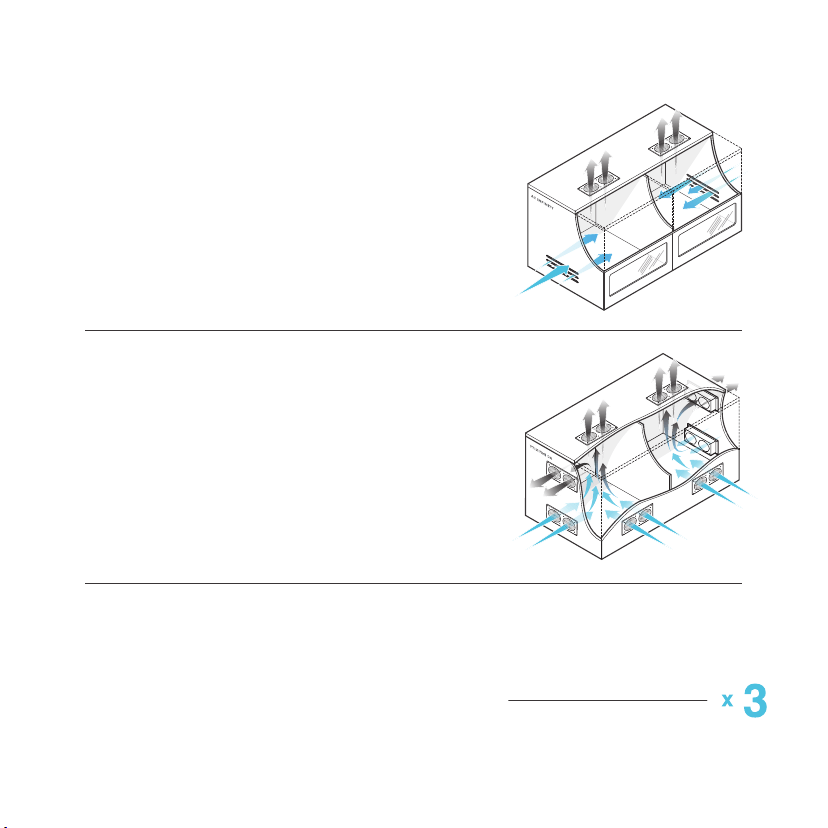
CONNECTING MORE FANS
Each fan unit includes an USB port that enables
you to connect an additonal fan. Up to four fans
can share the same USB port, and up to six fans
can share the same power outlet. Please see
page 16 for limitations.
T-SERIES CONTROLLER
Thermal controllers can control up to six fans. Some models may contain more
than one fan. For example AIRPLATE S7 contains two fans and AIRPLATE S9
contains three fans. Fan units connected to the thermal controller will share the
same speed and temperature settings. If the fans contain an inline speed
controller, please make sure their speed is set on high.
AC INFINITY
AC INFINITY
15
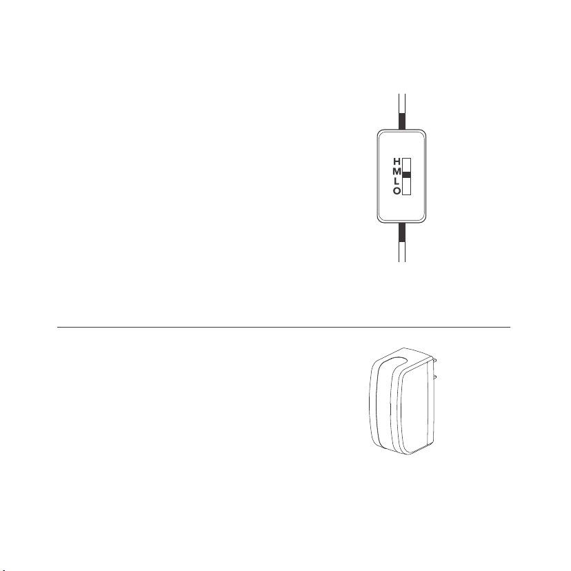
S-SERIES CONTROLLER
SPEED CONTROLLER
The speed controller located on the cord
allows you to adjust the fan’s speed from
off to low, medium, and high. Any fans that
are daisy chained will also have their speed
changed. All setups with more than four
daisy-chained fans must have their
inlinespeed controller set to high to prevent
overloading the speed controller, e.g. two
AIRPLATE S9 units daisy-chained together
must have their speeds set to high. Please
note that AIRPLATE S3/T3 contains one fan,
AIRPLATE S7/T7 contains two fans, and
AIRPLATE S9/T9 contains three fans.
TURBO BOOST ADAPTER
The Boost Adapter is designed to maximize the
performance of our fans. Using the adapter will
increase the fan’s speed by up to 25%. If the
higher speed is too loud for your application,
use the speed controller to reduce the noise
level.
16
17
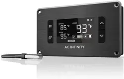
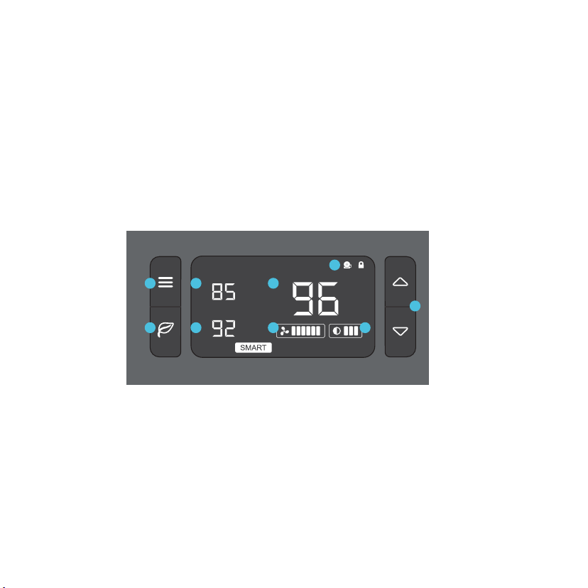
T-SERIES CONTROLLER
PROGRAMMING
1. MODE BUTTON
Cycles through the unit’s
modes: AUTO, SMART,
OFF, ON, ALARM. Hold
for three seconds will lock
or unlock the display.
2. UP / DOWN BUTTON
The up and down buttons
change the setting temp,
alarm temp, display
brightness, or the speed
of the fan.
3. LEAF BUTTON
This turns the display off
while allowing the
programs to run. Holding
will change degrees to
Fahrenheit or Celsius.
4. SETTING TEMP
Shows the temperature you
set the fans to trigger in
AUTO and SMART Mode.
5. ALARM TEMP
Shows the temperature
that you set the fan’s
alarm system to trigger.
6. PROBE TEMP
Actively shows current
temperature that the
probe is measuring.
7. FAN SPEED
Shows what speed the fans
are currently running at. Six
speeds are available.
8. BRIGHTNESS
Shows the brightness
of the display. Four
settings are available.
9. ALERT ICONS
Flashes to indicate if
alarm, or display
lock is being triggered.
1
3
2
ALARM
SETTING
F
o
F
o
PROBE
F
o
4
5
6
7
8
9
T-SERIES CONTROLLER
PROGRAMMING
QUICK START
Press the MODE button until you are on AUTO mode. This mode works like a thermostat. Then
press the up and down triangle buttons to change the SETTING temperature on the screen. The
PROBE temperature is what the thermal probe is measuring. When the PROBE temperature
exceeds the SETTING temperature, the fans will start running.
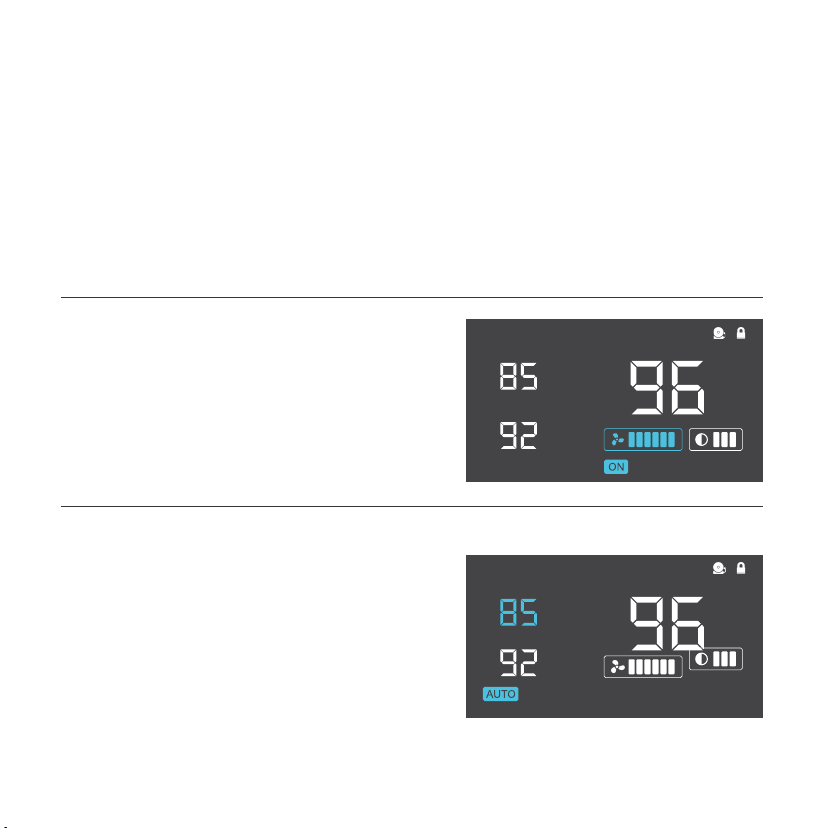
ON MODE
In this mode, the fans will run non-stop regardless
of temperature. Pressing the up and down buttons
while in this mode will change the speed of the fan.
Whichever speed is designated in this mode will
also be the speed used in AUTO Mode and the
max speed of the fans in SMART Mode.
AUTO MODE
This is the thermostat setting where the fans will
start running when the PROBE temperature
reaches or surpasses the SETTING temperature.
The SETTING temperature can be designated by
pressing the up and down buttons while in this
mode. Once the fans start running, the PROBE
temperature would need to fall at least 4° F below
the SETTING temp for the fans to stop running.
This variation buffer can be changed to 2° F.
See page 21 for more information.
18
ALARM
SETTING
F
o
F
o
PROBE
F
o
ALARM
SETTING
F
o
F
o
PROBE
F
o
T-SERIES CONTROLLER
PROGRAMMING
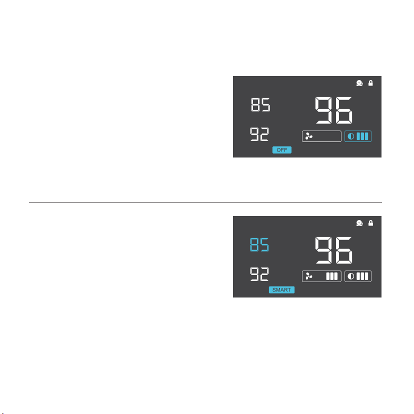
OFF MODE
In this mode, the fans are powered off
regardless of set temperature or set speed.
The backlight setting can be increased or
decreased by pressing the up or down
buttons while in this mode. If the first and
the third brightness bar light up and the
device is left unattended for 30 seconds,
the display will automatically dim its
brightness back to the dimmest setting.
SMART MODE
This is the energy saving mode where the fans
will change speed depending on the temper-
ature. The SETTING temperature can
be designated by pressing the up and down
triangle buttons while in this mode. For every
4°F increment that the PROBE temperature is
below the SETTING temperature, the speed of
the fans will decrease by one level. This
increment can be changed to 2°F; please see
page 21 for more information. The fan speed
you designated in ON Mode will also be the
max speed the fan’s can reach. This occurs
when the PROBE temperature reaches or
exceeds the SETTING temperature.
19
ALARM
SETTING
F
o
F
o
PROBE
F
o
ALARM
SETTING
F
o
F
o
PROBE
F
o
T-SERIES CONTROLLER
PROGRAMMING
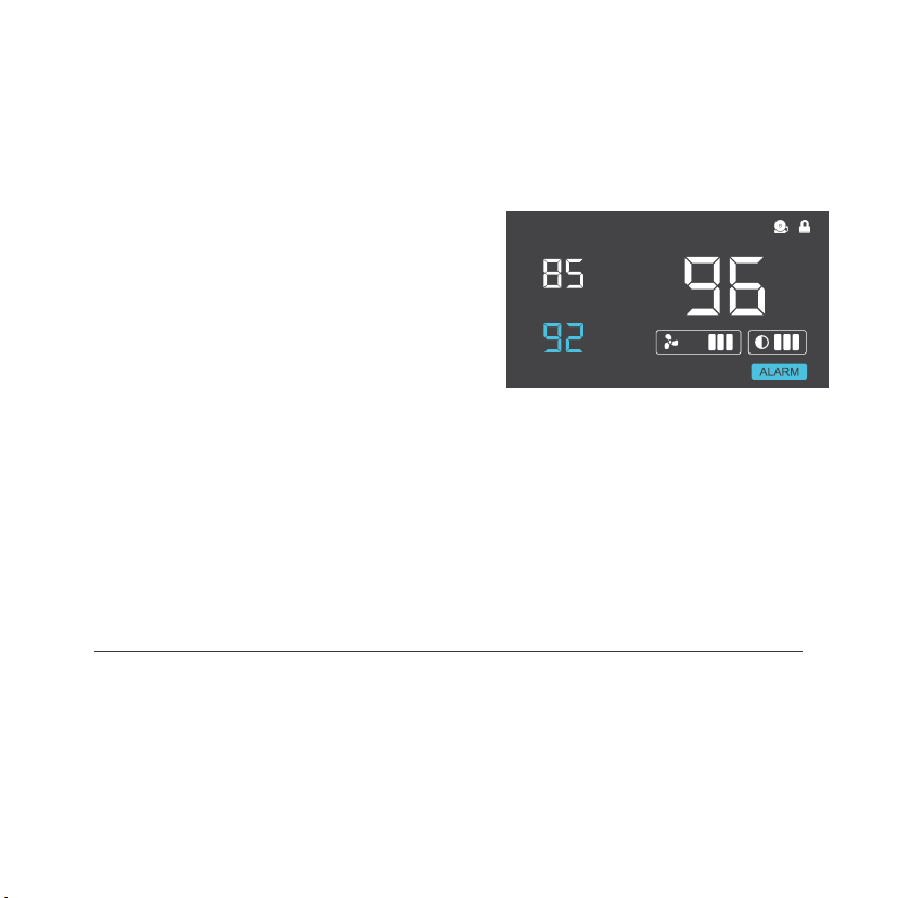
ALARM SETTING
In this mode, you can set what temperature
the system’s alarm will trigger by pressing
the up and down triangle buttons. When the
PROBE temperature reaches or exceeds
the ALARM temperature, the alarm will
activate. The alarm will only activate while the
controller is in ON, AUTO, or SMART Mode
so please remember to exit ALARM Mode
once the alarm has been set. When the alarm
is triggered, the fan’s will run at max speed
regardless of mode and will make an audible
beep every three seconds. This will keep
occurring until the temperature drops below
the ALARM temp or if any buttons are pressed.
The alarm can be disabled by pressing the
triangle button until the ALARM temp says
" OFF"
FAHRENHEIT OR CELSIUS
The temperatures displayed can be set to Fahrenheit or Celsius scale by holding
the LEAF button until °F or °C is shown after the digits. All digits displayed will be
automatically converted to the designated scale. (For Controller 8, hold the
ZONE CHANGE button instead.)
20
ALARM
SETTING
F
o
F
o
PROBE
F
o

T-SERIES CONTROLLER
PROGRAMMING
VARIATION BUFFER
In AUTO mode, a buffer is built in to prevent your fan from turning on and off too
quickly due to small variations in the environment. When the PROBE temperature
exceeds your SETTING temperature, the fan will start running immediately.
However, the PROBE temperature will need to fall below your SETTING
temperature by 4° Fahrenheit or 2° Celsius or more, to stop the fans from running.
In SMART mode, the speed of the fan will decrease by one level for every
4° Fahrenheit or 2° Celsius that the PROBE temperature is below the SETTING
temperature. To change this buffer or increment setting to 2° Fahrenheit or
1° Celsius, hold the MODE button and DOWN button together for three seconds.
To change back to 4° Fahrenheit or 2° Celsius, hold the MODE button and UP
button together for three seconds.
CONTROLLER LOCK
Holding the MODE button for three or more seconds will lock the controller. The
controller will still work as programmed; however, pressing any buttons will not
have an effect and will cause the screen lock icon to flash. This option was
designed to prevent your controller settings from being changed by accident.
Holding the MODE button again for three or more seconds will unlock the
controller.
21
ALARM
SETTING
F
o
F
o
PROBE
F
o
T-SERIES CONTROLLER
PROGRAMMING
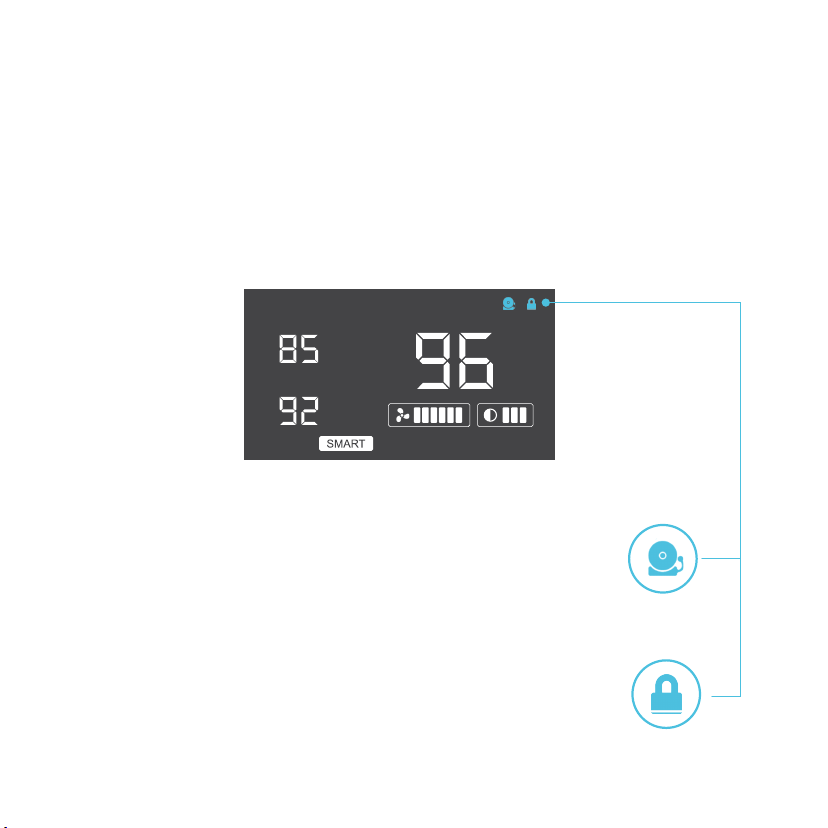
ALERT ICONS
On the top right of the display there are two alert icons. They are visible to
show that the system’s functions are being monitored. They will flash when the
controller wishes to alert you that a particular function is being triggered.
DISPLAY LOCK ALERT
This icon is not visible when the controller is unlocked. The icon
will flash when any buttons are pressed while the controller is
locked. Please see page 21 for more information on locking the
display.
ALARM ALERT
The alarm alert icon will flash when the probe temperature
reaches or exceeds the alarm temperature you have set. Please
see page 20 for more information on setting up the alarm.
22
MULTIZONE CONTROLLER
CONTROLLER 8
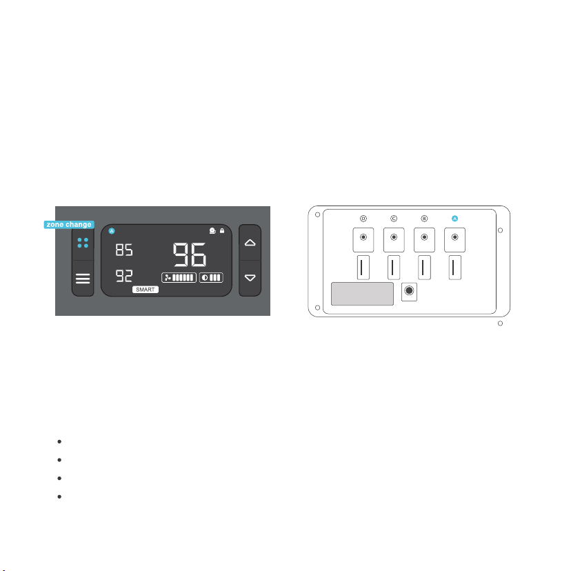
MULTIZONE CONTROLLER
The Multizone controller enables you to control cooling fans in four different zones with
independent programming settings for each zone. Pressing the zone change button
will cycle through these zones as shown by A, B, C, and D icons on the LCD display.
On the back side of the controller, there will be one probe and fan port underneath each
corresponding A, B, C, and D designation.
PROGRAMMING MODES
For every zone, you may press the MODE button to cycle through the programming modes:
Auto, Smart, On, Off, and Alarm. The modes work the same way as the standard controller
and each zone can have its own custom mode settings. Please refer to pages 17 to 22 for
programming instructions but with the differences listed below.
23
AC INFINITY
POWER
SENSOR
FANS
LABEL
ALARM
SETTING
F
o
F
o
PROBE
F
o
OTHER SETTING DIFFERENCES
Hold the ZONE button to set the display to Fahrenheit or Celsius, page 17.
Hold the MODE button to lock or unlock the display, page 21.
Hold ZONE and MODE buttons to turn the display off while programs run, page 17.
Hold UP and DOWN buttons to reset the controller to factory settings.

AIRPLATE FAQ
AIRPLATE SERIES
For common questions on your fan unit we have created an faq for your convience, if you have
any further questions that you don't see included plase email us at support@acinfinity.com and
we would be happy to help you!
Q: Can I mount this cabinet fan vertically?
A: Yes. The AIRPLATE can be mounted in any orientation, including vertically.
Q: How do I flip the fan to create intake or exhaust airflow?
A: To flip the fan blades, unscrew the bolts from the frontplate and the body. Flip the fans within
the body and screw the bolts back in. This does not apply to the AIRPLATE S2.
Q: Can I splice the cables to extend them or use my own probe?
A: We do not recommend hardwiring or splicing our fan's power wires. Such modifications may
compromise electrical safety and will void this product's warranty.
Q: Does this fan fit with filters?
A: The AIRPLATE fan is not compatible with any filters.
Q: Will I be able to mount this fan on a wall?
A: This product is not specifically designed to be mounted on or through a wall.
Q: Is this fan fit for outside applications?
A: This product is not specifically designed for outside use.
Q: Is it normal to hear a humming sound after flipping the fan?
A: A humming noise that occurs after flipping the fan from exhaust to intake is normal and will
not impact performance.
Q: How many additional fans can I connect with my cabinet fan?
A: Up to four fans can share the same USB power source. Up to six fans can share the same
thermal controller or wall outlet power source.
24
AC INFINITY PRODUCTS
AIRCOM SERIES
The AIRCOM component fan system cools receivers,
amplifiers, and other AV components. S-Series models
feature a thermal trigger and speed control. T-Series
features a LCD digital display with thermal and speed
control, alarm alerts, failure triggers, and backup memory.
DIMENSIONS
11.6 x 6.3 x 1.5 in.
11.6 x 6.3 x 1.5 in.
17 x 13.5 x 1.5 in.
17 x 13.5 x 1.5 in.
17 x 13.5 x 1.5 in.
17 x 13.5 x 1.5 in.
PRODUCT
AIRCOM S6
AIRCOM S7
AIRCOM S8
AIRCOM S9
AIRCOM T8
AIRCOM T9
MODEL
AI-ACS6
AI-ACS7
AI-ACS8
AI-ACS9
AI-ACT8
AI-ACT9
DIMENSIONS
3.1 x 3.1 x 1 in.
4.7 x 4.7 x 1 in.
5.5 x 5.5 x 1 in.
3.1 x 3.1 x 1 in. /fan
4.7 x 4.7 x 1 in. /fan
PRODUCT
MULTIFAN S1
MULTIFAN S3
MULTIFAN S4
MULTIFAN S5
MULTIFAN S7
MODEL
AI-MPF80A
AI-MPF120A
AI-MPF140A
AI-MPF80A2
AI-MPF120A2
MULTIFAN SERIES
The MULTIFAN series fans can be placed on top of AV
components and electronics to exhaust hot air economically.
It features an inline speed controller and can be powered by
an USB port. The fans can also be powered through a power
outlet with a Boost Speed Adapter (sold separately).
25
This warranty program is our commitment to you, the product sold by AC Infinity
will be free from defects in manufacturing for a period of two years from the date
of purchase. If a product is found to have a defect in material or workmanship, we
will take the appropriate actions defined in this warranty to resolve any issues.
The warranty program applies to any order, purchase, receipt, or use of any
products sold by AC Infinity or our authorized dealerships. The program covers
products that have become defective, malfunctioned, or expressively if the
product becomes unusable. The warranty program goes into effect on the date of
purchase. The program will expire two years from the date of purchase. If your
product becomes defective during that period, AC Infinity will replace your
product with a new one or issue you a full refund.
The warranty program does not cover abuse or misuse. This includes physical
damage, submersion of the product in water, incorrect Installation such as wrong
voltage input, and misuse for any reason other than intended purposes. AC
Infinity is not responsible for consequential loss or incidental damages of any
nature caused by the product. We will not warrant damage from normal wear
such as scratches and dings.
For more information about our dealers and distributors, please contact our customer service
at [email protected] or (626) 923-6399 Monday to Friday (9:00 am to 5:00 pm PST).

COPYRIGHT © 2021 AC INFINITY INC. ALL RIGHTS RESERVED
No part of the materials including graphics or logos available in this booklet may be
copied, photocopied, reproduced, translated or reduced to any electronic medium or
machine readable form, in whole or in part, without specific permission from AC Infinity Inc.

www.acinfinity.com